Professional�Courseware��
Mastercam�X4�Mill�Level�3�
To�order�more�books:�Call�1�800�529�5517�or�
Visit�www.inhousesolutions.com�or�Contact�your�Mastercam�Dealer�


Mastercam��X4�Training�Tutorials�–�Professional�Courseware�Mill�Level�3�Date:�June�10,�2009�Copyright�©�1984���2009�In�House�Solutions�Inc.�All�rights�reserved.�Author:�Mariana�Lendel�ISBN:�978�1�926566�31�3���
Notice��
In�House�Solutions�Inc.�reserves�the�right�to�make�improvements�to�this�manual�at�any�time�and�without�notice.��
Disclaimer�of�All�Warranties�and�Liability��
In�House�Solutions�Inc.�makes�no�warranties,�either�express�or�implied,�with�respect�to�this�manual�or�with�respect�to�the�software�described�in�this�manual,�its�quality,�performance,�merchantability,�or�fitness�for�any�particular�purpose.�In�House�Solutions�Inc.�manual�is�sold�or�licensed�"as�is."�The�entire�risk�as�to�its�quality�and�performance�is�with�the�buyer.�Should�the�manual�prove�defective�following�its�purchase,�the�buyer�(and�not�In�House�Solutions�Inc.,�its�distributor,�or�its�retailer)�assumes�the�entire�cost�of�all�necessary�servicing,�repair,�or�correction,�and�any�incidental�or�consequential�damages.�In�no�event�will�In�House�Solutions�Inc.�be�liable�for�direct,�indirect,�or�consequential�damages�resulting�from�any�defect�in�the�manual,�even�if�In�House�Solutions�Inc.�has�been�advised�of�the�possibility�of�such�damages.�Some�jurisdictions�do�not�allow�the�exclusion�or�limitation�of�implied�warranties�or�liability�for�incidental�or�consequential�damages,�so�the�above�limitation�or�exclusion�may�not�apply�to�you.��
Copyrights�
This�manual�is�protected�under�the�copyright�laws�of�Canada�and�the�United�States.�All�rights�are�reserved.�This�document�may�not,�in�whole�or�part,�be�copied,�photocopied,�reproduced,�translated�or�reduced�to�any�electronic�medium�or�machine�readable�form�without�prior�consent,�in�writing,�from�In�House�Solutions�Inc.��
Trademarks��
Microsoft,�the�Microsoft�logo,�MS,�and�MS�DOS�are�registered�trademarks�of�Microsoft�Corporation;�Mastercam�Verify�is�created�in�conjunction�with�Sirius�Systems�Corporation;�Windows�95,�Windows�NT;�and�Windows�XP�are�registered�trademarks�of�Microsoft�Corporation.��Acknowledgements:��Special�Thanks�to:�Andrew�Bleau�for�his�help�revising�this�book.��
In�House�Solutions�team�for�their�recommendations�and�input.��Sincerely,�Mariana�Lendel�


3D�GEOMETRY�CREATION�CONTENT��1.�ABOUT�STANDARD�PLANES�(TOP,�FRONT,�SIDE,�3D/ISOMETRIC)�AND�CONSTRUCTION�DEPTH. .............2�2.�USER�DEFINED�CONSTRUCTION�PLANES�/GRAPHIC�VIEWS�USING�GEOMETRY�AND�ROTATE ................. 4�3.�USER�DEFINED�CONSTRUCTION�PLANES�/�GRAPHIC�VIEWS�USING�NORMAL. ......................................... 5�4.�CREATE�DRAWING�#�1 ............................................................................................................................... 6�5.�CREATE�DRAWING�#�2 ............................................................................................................................... 7�6.�CREATE�DRAWING�#�3 ............................................................................................................................... 8�7.�CREATE�DRAWING�#�4 ............................................................................................................................... 9�8.�CREATE�DRAWING�#�5 .............................................................................................................................10�9.�CREATE�DRAWING�#�6 .............................................................................................................................13�10.�CREATING�CURVES�AT�THE�EDGES�AND�AT�THE�INTERSECTION�OF�SURFACES. ...................................15�11.�CREATE�DRAWING�#7............................................................................................................................16�SURFACE�GEOMETRY�CREATION.................................................................................................................20�GEOMETRICAL�SURFACES;�REVOLVED,�DRAFT,�EXTRUDED�&�PRIMITIVES .................................................20�12.�SURFACE�DRAWING�#1.�CREATE�REVOLVED�SURFACE .........................................................................20�13.�SURFACE�DRAWING�#8.�REVIEW���CREATE�REVOLVED�SURFACE..........................................................22�14.�SURFACE�DRAWING�#11.�CREATE�DRAFT�SURFACE�&�FLAT�BOUNDARY�SURFACE ..............................23�15.�EXERCISES�USING�CREATE�DRAFT�AND�EXTRUDED�SURFACE�COMMAND............................................25�16.�EXERCISES�USING�PRIMITIVES...............................................................................................................27�FREE�FORM�SURFACES;�RULED,�LOFT,�NET,�SWARF�&�FENCE.....................................................................29�17.�SURFACE�DRAWING�#6.�CREATE�RULED�AND�LOFT�SURFACES.............................................................29�18.�CREATE�RULED�SURFACES�WITHOUT�SYNCHRONIZATION�AND�WITH�SYNCHRONIZATION .................32�19.�CREATE�RULED/LOFT�SURFACES�USING�WINDOW�SELECTION. ............................................................33�20.�SURFACE�DRAWING�#3.CREATE�NET�SURFACES�&�FLAT�BOUNDARY�SURFACES. .................................34�21.�CREATE�NET�SURFACES�USING�WINDOW�SELECTION...........................................................................36�22.�SURFACE�DRAWING�#15.�REVIEW�EXERCISE�CREATE�A�NET�SURFACE. ................................................39�23.�SURFACE�DRAWING�#14.�REVIEW�EXERCISE�CREATE�A�NET�SURFACE. ................................................40�24.�CREATE�SWEPT�SURFACES. ...................................................................................................................41�25.�CREATE�SWEPT�SURFACES�USING�TRANSLATE�AND�ROTATE�OPTIONS ................................................44�26.�SURFACE�DRAWING�#18.CREATE�SWEPT�SURFACES. ...........................................................................46�27.�CREATE�SWEPT�SURFACES�WITH�SHARP�EDGES ...................................................................................47�28.�CREATE�SWEPT�SURFACES,�CURVES�AT�THE�SURFACE�EDGES�AND�A�FLAT�BOUNDARY�SURFACE.......47�29.�CREATE�FENCE�SURFACE. ......................................................................................................................54�DERIVED�SURFACES;�OFFSET,�TRIM,�FILLET,�2�SURFACE�BLEND�&�3�SURFACE�BLEND�&�FILLET�BLEND .....55�30.�SURFACE�DRAWING�#4.�CREATE�OFFSET�SURFACE...............................................................................55�31.CREATE�SURFACE�TRIM�TO�CURVES.......................................................................................................56�32.CREATE�SURFACE�TRIM�TO�SURFACE. ....................................................................................................59�33.CREATE�SURFACE�TRIM�TO�PLANE;�SURFACE�FILLET�TO�SURFACE. .......................................................62�34.CREATE�SURFACE�FILLET�TO�SURFACE�&�SURFACE�FILLET�TO�PLANE. ...................................................67�35.�REVIEW�EXERCISE..................................................................................................................................70�36.CREATE�3�FILLET�BLEND�SURFACES. .......................................................................................................71�37.CREATE�2�SURFACE�BLEND.....................................................................................................................75�38.CREATE�3�SURFACE�BLEND.....................................................................................................................76�39.�REVIEW�EXERCISE..................................................................................................................................78DRAWINGS�
�
�
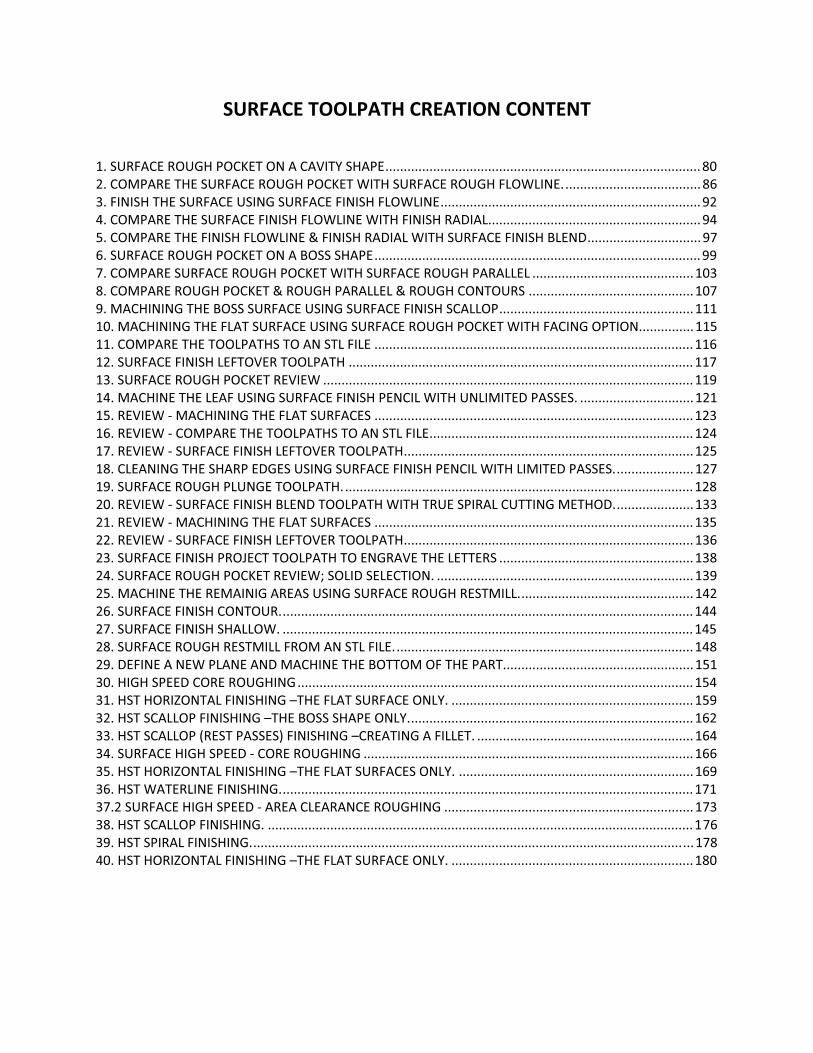
SURFACE�TOOLPATH�CREATION�CONTENT���1.�SURFACE�ROUGH�POCKET�ON�A�CAVITY�SHAPE......................................................................................80�2.�COMPARE�THE�SURFACE�ROUGH�POCKET�WITH�SURFACE�ROUGH�FLOWLINE......................................86�3.�FINISH�THE�SURFACE�USING�SURFACE�FINISH�FLOWLINE.......................................................................92�4.�COMPARE�THE�SURFACE�FINISH�FLOWLINE�WITH�FINISH�RADIAL..........................................................94�5.�COMPARE�THE�FINISH�FLOWLINE�&�FINISH�RADIAL�WITH�SURFACE�FINISH�BLEND...............................97�6.�SURFACE�ROUGH�POCKET�ON�A�BOSS�SHAPE.........................................................................................99�7.�COMPARE�SURFACE�ROUGH�POCKET�WITH�SURFACE�ROUGH�PARALLEL ............................................103�8.�COMPARE�ROUGH�POCKET�&�ROUGH�PARALLEL�&�ROUGH�CONTOURS .............................................107�9.�MACHINING�THE�BOSS�SURFACE�USING�SURFACE�FINISH�SCALLOP.....................................................111�10.�MACHINING�THE�FLAT�SURFACE�USING�SURFACE�ROUGH�POCKET�WITH�FACING�OPTION...............115�11.�COMPARE�THE�TOOLPATHS�TO�AN�STL�FILE .......................................................................................116�12.�SURFACE�FINISH�LEFTOVER�TOOLPATH ..............................................................................................117�13.�SURFACE�ROUGH�POCKET�REVIEW .....................................................................................................119�14.�MACHINE�THE�LEAF�USING�SURFACE�FINISH�PENCIL�WITH�UNLIMITED�PASSES. ...............................121�15.�REVIEW���MACHINING�THE�FLAT�SURFACES .......................................................................................123�16.�REVIEW���COMPARE�THE�TOOLPATHS�TO�AN�STL�FILE........................................................................124�17.�REVIEW���SURFACE�FINISH�LEFTOVER�TOOLPATH...............................................................................125�18.�CLEANING�THE�SHARP�EDGES�USING�SURFACE�FINISH�PENCIL�WITH�LIMITED�PASSES......................127�19.�SURFACE�ROUGH�PLUNGE�TOOLPATH................................................................................................128�20.�REVIEW���SURFACE�FINISH�BLEND�TOOLPATH�WITH�TRUE�SPIRAL�CUTTING�METHOD......................133�21.�REVIEW���MACHINING�THE�FLAT�SURFACES .......................................................................................135�22.�REVIEW���SURFACE�FINISH�LEFTOVER�TOOLPATH...............................................................................136�23.�SURFACE�FINISH�PROJECT�TOOLPATH�TO�ENGRAVE�THE�LETTERS .....................................................138�24.�SURFACE�ROUGH�POCKET�REVIEW;�SOLID�SELECTION. ......................................................................139�25.�MACHINE�THE�REMAINIG�AREAS�USING�SURFACE�ROUGH�RESTMILL................................................142�26.�SURFACE�FINISH�CONTOUR.................................................................................................................144�27.�SURFACE�FINISH�SHALLOW. ................................................................................................................145�28.�SURFACE�ROUGH�RESTMILL�FROM�AN�STL�FILE..................................................................................148�29.�DEFINE�A�NEW�PLANE�AND�MACHINE�THE�BOTTOM�OF�THE�PART....................................................151�30.�HIGH�SPEED�CORE�ROUGHING............................................................................................................154�31.�HST�HORIZONTAL�FINISHING�–THE�FLAT�SURFACE�ONLY. ..................................................................159�32.�HST�SCALLOP�FINISHING�–THE�BOSS�SHAPE�ONLY..............................................................................162�33.�HST�SCALLOP�(REST�PASSES)�FINISHING�–CREATING�A�FILLET. ...........................................................164�34.�SURFACE�HIGH�SPEED���CORE�ROUGHING ..........................................................................................166�35.�HST�HORIZONTAL�FINISHING�–THE�FLAT�SURFACES�ONLY. ................................................................169�36.�HST�WATERLINE�FINISHING.................................................................................................................171�37.2�SURFACE�HIGH�SPEED���AREA�CLEARANCE�ROUGHING ....................................................................173�38.�HST�SCALLOP�FINISHING. ....................................................................................................................176�39.�HST�SPIRAL�FINISHING.........................................................................................................................178�40.�HST�HORIZONTAL�FINISHING�–THE�FLAT�SURFACE�ONLY. ..................................................................180���
�
�
Mill�Level�3�������������������������������������������������������������������������������������������������������������������SURFACE�TOOLPATH�CREATION��
HIGH�SPEED�SURFACE�TOOLPATH�CREATION�30.�HIGH�SPEED�CORE� ��
ROUGHING
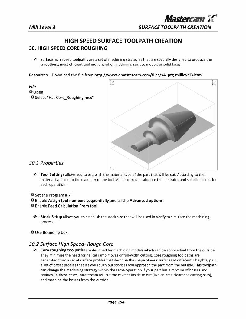
Surface�high�speed�toolpaths a�set�of�machining�strategies�that�are�specially�designed�to�produce�thesmoothest,�most�efficient�to otions�when�machining�surface�models�or�solid�faces.�
�are� �ol�m
�R ww emastercam.com/files/x4_ptg�milllevel3.html�
ile�
esources�–�Download�the�file�from�http://w .�FOpen�Select�“Hst�Core_Roughing.mcx”�
0.1�Properties�
�����������
3�
Tool�Settings�allows�you�to�establish�the�material�type�of�the�part�that�will�be�cut.�According�to�the�ds�for�material�type�and�to�the�diameter�of�the�tool�Mastercam�can�calculate�the�feedrates�and�spindle�spee
each�operation.����
Set�the�Program�#�7��Enable�Assign�tool�numbers�sequentially�and�all�the�Advanced�options.�Enable�Feed�Calculation�From�tool�
�Stock�Setup�allows�you�to�establish�the�stock�size�that�will�be�used�in�Verify�to�simulate�the�machining�
�process.��
Use�Bounding�box.�
0.2�Surface�High�Speed��Rough�Core��
3Core�roughing�toolpaths�are�designed�for�machining�models�which�can�be�approached�from�the�outside.�
�the�need�for�helical�ramp�moves�or�full�width�cutting.�Core�roughing�toolpaths�are��a�set�of�surface�profiles�that�describe�the�shape�of�your�surfaces�at�different�Z�heights,�plus�
f�offset�profiles�that�let�you�rough�out�stock�as�you�approach�the�part�from�the�outside.�This�toolpath�can�change�the�machining�strategy�within�the�same�operation�if�your�part�has�a�mixture�of�bosses�and�
�an�area�clearance�cutting�pass),�and�machine�the�bosses�from�the�outside.�
They�minimizeted�fromgenera
a�set�o
cavities.�In�these�cases,�Mastercam�will�cut�the�cavities�inside�to�out�(like
� Page�154� �

�
�
Mill�Level�3�������������������������������������������������������������������������������������������������������������������SURFACE�TOOLPATH�CREATION��Toolpaths�Surface�High�Speed…�
�Select�all�surfaces��
�To pol ath�Type��
The�Toolpath�Type�dialog�box�allows�you�to�select�the�toolpath�between�rough�and�finish�operations.�It�ange�the�drive/check�surfaces�that�you�selected�and�the��also�allows�you�to�ch
Containment�and�the�Approximate�start�point.��
Select�Roughing�and�Core�Roughing��Tool��
Allows�you�to�select�a�tool,�edit�its�prwill�be�output�in�the�NC�file�after�run
operties,�and�enter�feeds�and�speeds.�You�can�insert�a�comment�that�ning�the�post�processor.�
�Select�the�0.50”�Bull�Nose�with�the�corner�radius�of�0.0625.�
�oH
�lder�
Allows�you�to�select�the�tool�holder�to�be�used�in�the�operation.�You�can�also;�create�a�holder�definition,�ou�can�check�the�holder�for�
�
load�a�holder�from�a�library�or�edit�the�holder�after�it�has�been�selected.�Ygouge.�
Select�Open�library�and�from�CAT�40�select�C4C4�0016��ut�parameters�C
�The�Cut� �dialog�box�allows�you
s�in �plane;�Smoothing�to�round�the�corners�of�the�toolpath�to�maintain�a�higher�feedrate.�You�can�also�establish�the�Stock�to�leave�on�walls�and�on�floors.�You�can�set�how�to�control�the�tool's�position�around�the�boundary�of�the�part.�
tepdown�
parameters �to�establish�the�Stepdown�for�the�cuts�in�Z;�XY�stepover�to�set�the�passe �XY
�S
Set�the�Stepdown�to�0.05�and�enable�Add�cuts�with�a�Min�stepdown�=�0.05�and�Max�profile�stepover�=�0.25;�
�Use�Add�cuts�feature�to�insert�additional�cutting�passes�in�the�shallow�areas.�
Y�stepover��X
Set�the�%�of�dia�=�50�this�will�automatically�update�the�Min�and�Max�distances��
If�you�are�using�toolpath�smoothing,�make�sure�that�the�minimum�stepover�is�greater�than�the�Offset�Tolerance�value�and�less�than�the�radius�of�the�tool�shaft.�The�maximum�stepover�should�be�less�than�twice�the�minimum�stepover.�
� Page�155� �
�
�
Mill�Level�3�������������������������������������������������������������������������������������������������������������������SURFACE�TOOLPATH�CREATION��Smoothing�
Set�Max�radius=�0.025��
Max�radius�limits�the�size�of e�arcs�Mastercam�will�create�to�round�the�th �corners��
Profile�tolerance�=�0.005�
ool�containment��T
Enable�Center�in�the�Tool�containment���
Tool�containment�allows�you�to�select�the�closed�contour�inside�of�which�the�tool�will�machine�the�part.��
Stock�to�leave�on�walls�=�0.05�Stock�to�leave�on�floor�=�0.05�
�Note�that�the�stock�to�leave�on�walls�must�be�greater�than�or�equal�to�the�stock�left�on�the�floor.�The�only�exception�is�for�horizontal�area�finish�passes.��
rochoidal�motion�leave�it�off��T�
Minimize�burial�enabled�will�have�Mastercam�automatically�insert�trochoidal�loops�in�the�toolpath�in�areas�where�the�tool�might�be�fully�buried.�
�Entry�helix��
Set�Radius�=�0.175�Enable�Output�3D�arc�moves�Steep/shallow�not�enable�
inking�Parameters��L�
Creates�the�links�between�the�cutting�passes.the�tool�is�not�in�contact�with�the�part�
etract�method�
�In�general,�you�can�think�of�linking�moves�as�air�moves�when�
�R
Enable�Minimum�distance�to�insert�high�speed�arcs�to�and�from�the�retract�height�and�maintains�a�minimum�retract�height�above�the�surface�for�the�fastest�transitions.�
etracts�REnter�the�size�of�the�arc�in�the�Curl�up�(arc�to�the�retract�height)�=�0.15�Enter�the�size�of�the�arc�Curl�down�(arc�from�the�retract�height)�=�0.15.�Part�clearance�=�0.15�
� Page�156� �

�
�
Mill�Level�3�������������������������������������������������������������������������������������������������������������������SURFACE�TOOLPATH�CREATION��
�
�
Mill�Level�3�������������������������������������������������������������������������������������������������������������������SURFACE�TOOLPATH�CREATION��
� Page�157� �
�Leads��
Controls�how�the�tool�moves�onto�and�off�of�the�part�at�the�start�and�end�of�each�cutting�pass.�These�moves�are�applied�to�each�pass�no�matter�which�cutting�pass�is�selected.�
�Linear�entry/exit�=�0.025�Vertical�arc�entry�=�0.075�
�Vertical�arc�exit�=�0.075�
�Fitting�
Controls�how�the�entry�and�exit�arcs�will�be�fit�into�each�pass.���
Set�to�Minimize�Trimming��
The�path�of�the�retract�will�be�as�close�to�the�surface�as�possible,�maintaining�a�minimum�distance�from�the�surface�to�fit�the�arc.�
�Set�the�Max�trimming�distance�=�0.0825�Select�the�OK�button�to�exit�
moothing��S�
Profile�tolerance�determines�the�maximum�deviation�between�the�smoothed�and�unsmoothed�toolpaths�
�on�the�outermost�profile�or�cutting�pass.�
Of .005625�fset�tolerance�=�0�
Offset�tolerance�is�define�similar�with�the�Profile�tolerance,�but�it�is�applied�to�all�the�inner�passes.��Arc�Filter/Tolerance��
Total�tolerance�displays�the�sum�of�the�filter�tolerance�and�cut�tolerance.�The�dialog�box�that�opens�wheyou�choose�theis�active�for
n��Total�Tolerance�button�depends�on�whether�the�3D�Advanced�Toolpath�Refinement�feature�
�the�Mastercam�session.��
Total�tolerance�=�0.002��
Refine�Toolpath�is�used�to�refine�mastercam’s�surface�and�high�speed�toolpaths,�reducing�machining�time�
��
and�improving�machined�surface�quality.�
“My�preferences�are”�Section�
To�automatically�define�the�total�tolerance�allocations�and�other�settings,�use�the�“wizard”�slider�controls�in�the�
� Page�157� �
�
�
Mill�Level�3�������������������������������������������������������������������������������������������������������������������SURFACE�TOOLPATH�CREATION����
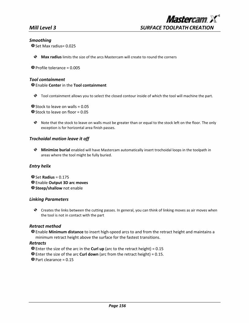
The�Tolerances�Distribution�fields�display�the�total�tolerance�you�defined�for�the�toolpath�and�the�formula�ers�between�the�fields�to�allocate�fixed�percentages�of�cut,�line/arc�filtering,�and�ces�in�5%�increments.�Or,�enter�the�percentages�directly�into�the�fields.��
used.�Use�the�slidsmoothing�toleran
�If�desired,�use�the�Line/Arc�Filtering�Settings�and�Smoothing�Settings�to�
�
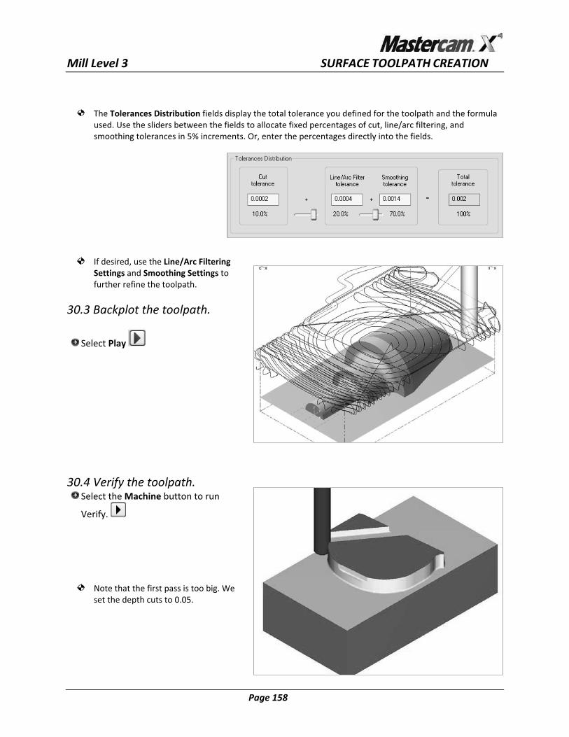
0.3�Backplot�the�toolpath.�
further�refine�the�toolpath.��
3�
Select�Play� �
���
�
�
30.4�
�
�
���
Verify�the�toolpath.�Se
Verify.�
lect�the�Machine�button�to�run�
�
�
��
��
Note�that�the�first�pass�is�too�big.�We�set�the
��depth�cuts�to�0.05.�
� Page�158� �

�
�
Mill�Level�3�������������������������������������������������������������������������������������������������������������������SURFACE�TOOLPATH�CREATION��
30.5� k.��
Use�the�Steep/Shallow�parameters�to�control�the�depth�cuts�from�the�stoc
Enable set�the�Minimum�depth�=�1.7�and�Maximum�depth�=�0.0��Regenerate,�then�Backplot�and�Verify�the�toolpath�����������������
31.�HST�HORIZONTAL�FINISHING�–THE�FLAT�SURFACE�ONLY��
31.1�Use�the�SilhouetteBoundary�C�Hook�to�create�a�boundary�around�the�shape.��
�Use�Z�depths�and�
Tips:�Set�Z�depth�to�3�and�make�sure�the�construction�plane�is�Top.���
Select�all�surfaces�and�unselect�the�bottom.�Use�Xform�offset�contour�and�offset�outside,�both�the�top�rectangle�(from�the�stock)�and�the�boundary,�with�a�0.2�offset�distance.�
�
� Page�159� �

�
�
Mill�Level�3�������������������������������������������������������������������������������������������������������������������SURFACE�TOOLPATH�CREATION��
31.2�Surface�High�Speed�Horizontal�Area��
High�Speed�Horizontal�Area�toolpaths�are�used�to�machine�the�flat�areas�of�the�surface�model.�t�areas�within�each�
surface.��
Mastercam�analyzes�the�selected�drive�surfaces�and�automatically�identifies�the�fla
Copy�the�operation�in�the�Operations�Manger��Select�the�Geometry�in�the�second�Operation�and�add�the�two�offset�chains�as�containment�boundaries.�
�Note�that�the�high�speed�toolpaths�allows�us�to�use�as�boundaries�nested�chains.��
�Select�the�Parameters�of�the�second�Operation.�
�Toolpath�Type�
Select�Finishing�and�Horizontal�Area��ool�TSelect�the�0.375”�Flat�endmill.�
�H eold r�
Se C4C4�0016�lect�Open�library�and�from�CAT�40�select�Enable�Use�holder�for�gouge�checking.�
ut�parameters��
�C
The�Cut�parameters�dialog�box�allows�you�to�establish�the�Depth�cuts;�the�XY�Stepover�for�the�spacing�oothing�to�round�the�corners�of�the�toolpath�to�maintain�a�higher�feedrate.�You�
can�also�establish�the�Stock�to�leave�on�walls�and�on�floors.�You�can�set�how�to�control�the�tool's�position�ary�of�the�part.�
between�cutting�passes;�Sm
around�the�bound�
S t�the�#�of�depth�cuts�to�1.�eXY�Stepover�Set�the�%of�dia�=�45.0�Smoothing�Set�Max�radius=�0.01875�Tool�containment�set�to�Inside�and�Offset�distance�=�0.0�and�enable�Add�offset�distance�to�tool�
�radius.Make�the�Stock�on�walls/floors�=0.�
�T�rochoidal�motion�leave�it�to�off.�
Select�Trochoidal�motion�to�have�Mastercam�automatically�insert�trochoidal�loops�in�the�toolpath�in�areas�where�the�tool�might�be�fully�buried.�
�Transition�
� Page�160� �

�
�
Mill�Level�3�������������������������������������������������������������������������������������������������������������������SURFACE�TOOLPATH�CREATION��
Set�the�transition�to�Entry�helix�to�insert�arcs�at�the�beginning�and�end�of�the�ramp�for�the�smoothest�motion�into�and�out�of�the�move.�tool�
Make�the�radius�=�0.2��Linking�Parameters�
Set�the�Retract�method�to�Minimum�Vertical�Retract.�Set�the�Part�clearance�to�0.075�Linear�entry/exit�=�0.025�Vertical�arc�entry�=�0.075�Vertical�arc�exit�=�0.075�Horizontal�arc�exit�=�0.075�Max�ramp�angle�=�10�Select�the�OK�button�to�exit.�
�Arc�Filter/Tolerance�Smoothing�Profile�tolerance�=�0.00375�Of 75�
��
1.3�Backplot�the�toolpath.�
fset�tolerance�=�0.03�
3�
Select�Play� ��
�
�
1.4�Verify�the�two�toolpath.�
�
�
��
3Select�the�Machine�button�to�run�Verify.�
���������
� Page�161� �

�
�
Mill�Level�3�������������������������������������������������������������������������������������������������������������������SURFACE�TOOLPATH�CREATION��
32.�HST�SCALLOP�FINISHING�–THE�BOSS�SHAPE�ONLY��
High�speed�scallop�toolpaths�differ�from�other�finish�toolpaths�in�that�the�stepover�distance�is�a�3D�value�which�is�measured�along�the�surface,�instead�of�parallel�to�the�tool�plane.�This�ensures�a�consistent�scallop�height�across�the�surface,�regardless�of�the�surface�direction.�
�Copy�the�operation�in�the�Operations�Manger��Select�the�Geometry�in�the�third�Operation�and�rechain�all�and�add�the�chain�created�with�the�C�Hook�as�the�containment�boundary.�
�Select�the�Parameters�of�the�third�Operation.�
�Toolpath�Type�
Select�Finishing�and�Scallop�
Tool��
Select�the�0.50”�Ball�end.��Holder�
Select�Open�library�and�from�CAT�40�select�C4C4�0016�Enable�Use �for�gouge�checking.�
�ut�parameters�
�holder
C�
The�Cut�parameters�dialog�box�allows�you�to�establish�the�Cutting�method;�the�Stepover�for�the�spacing�between�cutting�passes.�You�can�also�establish�the�Stock�to�leave�on�walls�and�on�floors.�You�can�set�how�to�control�the�tool's�position�around�the�boundary�of�the�part.�
utting�method��C
Set�the�Cutting�method�to�One�Way�to�machine�all�the�passes�in�a�single�default�direction.�Mastercam�tries�to�maintain�a�climb�milling�orientation�relative�to�the�surface�boundaries.�Make�sure�that�Expand�inside
Stepover��to�cut�is�not�enable.�
Set�the�stepover�=�0.050��Tool�con inta ment�set�to�Outside�and�Offset�distance�=�0.3.�Make�the�Stock�on�walls/floors�=0.�
ransition��T
Set�the�transition�to�Tangential�ramp�to�insert�arcs�at�the�beginning�and�end�of�the�ramp�for�the�smoothest�tool�motion�into�and�out�of�the�move.�
�Linking�Parameters�
Leave�the�parameters�as�set�for�the�Horizontal�Area�cut.�
� Page�162� �
�
�
Mill�Level�3�������������������������������������������������������������������������������������������������������������������SURFACE�TOOLPATH�CREATION��
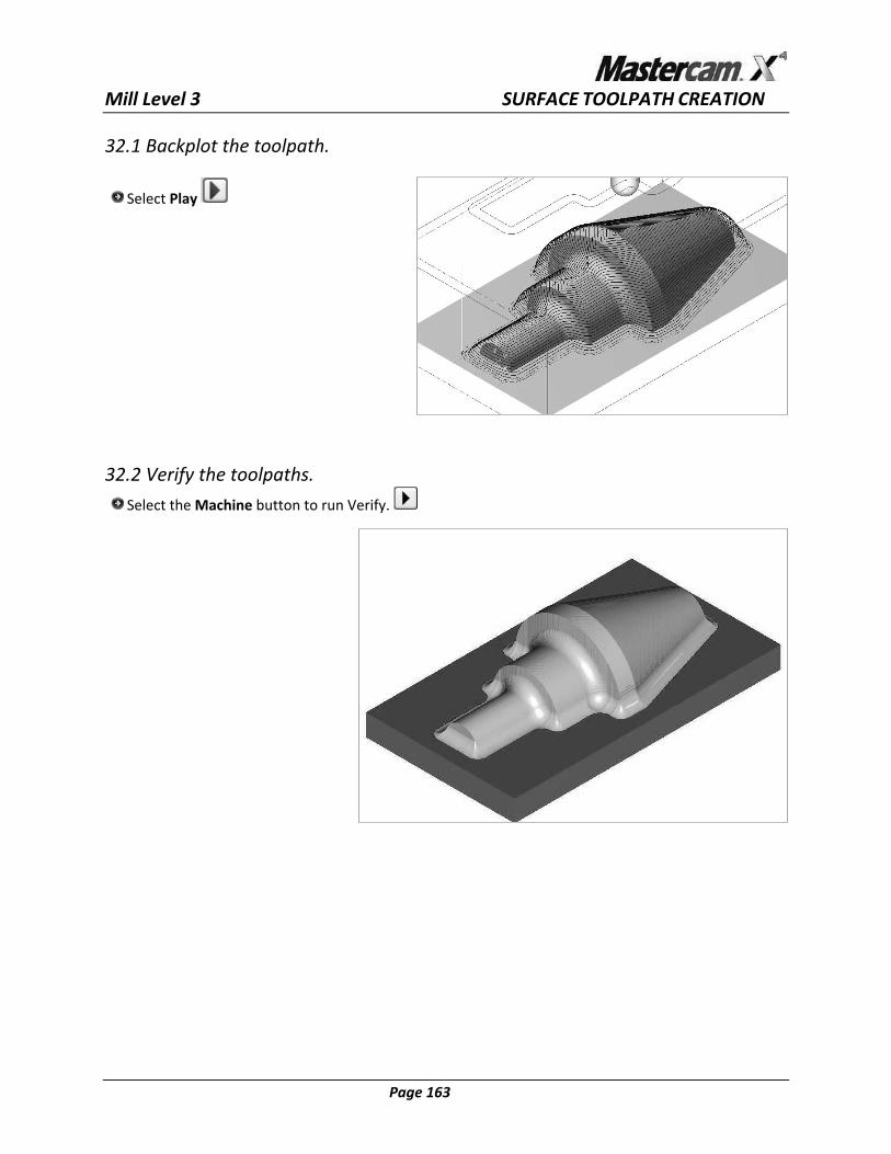
32.1�Backplot�the�toolpath.��
Select�Play� ��������������
32.2�Verify�the�toolpaths.�
Select�the�Machine�button�to�run�Verify.� ��
� Page�163� �

�
�
Mill�Level�3�������������������������������������������������������������������������������������������������������������������SURFACE�TOOLPATH�CREATION��
33.�HST�SCALLOP�(REST�PASSES)�FINISHING�–CREATING�A�FILLET��
High�speed�scallop�rest�passes�toolpaths�calculate�a�stock�model�based�on�the�dimensions�of�a�roughingtool�and�only�apply�the�toolpath�to�those�areas.�Use�them�for�applications�where�you�want�a�different�cutting�st
�
rategy�than�area�clearance�passes,�and�the�remaining�stock�is�light�enough�to�be�machined�with�a�single�cut.�
�Copy�the�operation�in�the�Operations�Manger��Select�the�Geometry�in�the�fourth�Operation�and�rechain�all�and�add�the�chain�created�with�the�C�Hook�as�the�containment�boundary.�
�Select�the�Parameters�of�the�fourth�Operation.�
�oolpath�Type�TLeave�the�Finishing�and�Scallop�
�ool�TSelect�the�0.1250”�Ball�end.�
�ut�parameters�C
�The�Cut�parameters�dialog�box�allows�you�to�establish�the�Cutting�method;�the�Stepover�for�the�spacing�
ablish�the�Stock�to�leave�on�walls�and�on�floors.�You�can�set�how��boundary�of�the�part.�
between�cutting�passes.�You�can�also�estto�control�the�tool's�position�around�the
�Cutting�method�
Set�the�Cutting�method�to�One�Way�to�machine�all�the�passes�in�a�single�default�direction.�Mastercam�tries�to�maintain�a�climb�milling�orientation�relative�to�the�surface�boundaries.�Make
Stepo�sure�that�Expand�inside�to�cut�is�not�enable.�
ver�Set�the�stepover�=�0.0125��Tool�containment�set�to�Outside�and�Offset�distance�=�0.3.�Make�the�Stock
��on�walls/floors�=0.�
Rest�material�Enable�Use�rest�material�
�the�Diameter�=�0.5�and�Corner�radius�=�0.25�Enable�Roughing�Tool�and�Transition�
Set�the�transition�to�Tangential�ramp�to�insert�arcs�at�the�beginning�and�end�of�the�ramp�for�the��of�the�move.�
in ing�Parameters�
smoothest�tool�motion�into�and�out�L k
Leave�the�parameters�as�set�for�the�Horizontal�Area�cut.�
� Page�164� �

�
�
Mill�Level�3�������������������������������������������������������������������������������������������������������������������SURFACE�TOOLPATH�CREATION��Arc�Filter/Tolerance�
Enable�Toolpath�fillet�and�set�the�Radius�=�0.1875��
Toolpath�fillet�option�tells�Mastercam�to�insert�an�arc�to�the�specified�radius�in�the�toolpath�at�sharp�corners.�The�radius�value�that�you�enter�here�should�be�at�least�as�large�as�the�radius�of�the�finish�tool.�
re�created�as�tool�motions�only.�They�are�not�saved�as�part�of�your�surface�model,�and�
�
3
Note:�The�fillets�athey�have�no�effect�on�your�part�geometry.��
2.1�Backplot�the�toolpath.�
Select�Play� �����
��
3 oolpaths.�
���
������
2.2�Verify�the�t
Select�the�Machine�button�to�run�Verify.� ��
� Page�165� �
Recommended