American Journal of Mechanical and Industrial Engineering 2016; 1(1): 1-9
http://www.sciencepublishinggroup.com/j/ajmie
doi: 10.11648/j.ajmie.20160101.11
Material Selection for High Pressure (HP) Turbine Blade of Conventional Turbojet Engines
Ikpe Aniekan Essienubong1, *
, Owunna Ikechukwu1, Patrick. O. Ebunilo
2, Ememobong Ikpe
3
1Department of Mechanical Engineering, Coventry University, West Midlands, UK 2Department of Mechanical Engineering, University of Benin, Benin City, Nigeria 3Department of Instrumentation and Control, Exxon Mobil Producing Nigeria, Akwa Ibom State, Nigeria
Email address: [email protected] (I. A. Essienubong), [email protected] (O. Ikechukwu),
[email protected] (Patrick. O. Ebunilo), [email protected] (E. Ikpe) *Corresponding author
To cite this article: Ikpe Aniekan Essienubong, Owunna Ikechukwu, Patrick. O. Ebunilo, Ememobong Ikpe. Material Selection for High Pressure (HP) Turbine
Blade of Conventional Turbojet Engines. American Journal of Mechanical and Industrial Engineering. Vol. 1, No. 1, 2016, pp. 1-9.
doi: 10.11648/j.ajmie.20160101.11
Received: June 5, 2016; Accepted: June 13, 2016; Published: June 23, 2016
Abstract: Turbojet engine can be divided into three major sections including the compressor, combustion chamber and the
gas turbine section. The relatively high temperature gas that passes through the high pressure turbine stages of a turbojet engine
from the combustion chamber has a direct effect on the performance and efficiency of the gas turbine, which may hamper its
longevity in the long run, particularly the turbine blades. The turbine blades extract energy from the high temperature gas and
transfer the kinetic energy of the flowing gas to the compressor stages where it provides forward thrust and rotates the turbine
shaft which drives the high pressure and low Pressure compressor fan blades. However, the ability of materials to withstand
this high temperature is based on properties of such materials which can be attributed to advances in material selection,
improvement techniques in terms of surface protection and cooling as well as manufacturing processes which this paper is
based on. Material indices were derived for High Pressure (HP) turbine blades to determine materials that can resist yielding
and creep condition when exposed to high temperature above 700°C in a turbojet engine gas turbine. Based on the material
indices derived, CES software 2014 was used to generate graphs showing materials with adequate fracture toughness, fatigue
strength, stiffness and yield strength property that can withstand the in-service condition of HP turbine blade. Considering all
these properties in terms of relatively high temperature, Nickel based super alloys dominated the graphs but in terms of density,
titanium alloys dominated as CES software gave the minimum density of nickel alloy (8150 kg/m3) as twice that of titanium
alloy (4410 kg/m3). Although both alloys are very expensive, nickel based alloy particularly Nickel-Cr-Co-Mo Super alloy also
known as Rene 41 was chosen because of its excellent corrosion property and high strength at elevated temperature (About
1000°C) which makes it suitable for conventional HP turbine blade application.
Keywords: Temperature, Failure, HP Turbine Blades, Cyclic Stresses, High Strength, Low Density, Turbojet Engine
1. Introduction
Turbojet engine is the power plant of modern day’s aircraft
jet systems as it does not only produce the trust required by
an aircraft for propulsion but also the power that enables the
operation of other components in the aircraft. A typical jet
engine operates with the principles of Newton’s third law of
motion which states that a given force exerted on a body will
generate equal and opposite force of action. The concept
behind turbojet engines was first demonstrated in 1937 by
Frank Whittle, an RAF cadet in early 1928 and this was the
first flight four years later [15, 11]. The jet engine operates
by sucking in some of the air while the aircraft is in motion,
compressing it to the smallest volume, mixing it with fuel
and burning it inside the combustion chamber and ejecting
hot gases from the hot air-fuel mixture with extremely high
force to propel the aircraft. The power capacity of such
engines can be expressed in pounds of thrust, a term that
describes the number of pounds the engine can travel [9, 12].
A typical jet engine is accommodated by a cowling, a
2 Ikpe Aniekan Essienubong et al.: Material Selection for High Pressure (HP) Turbine Blade of Conventional Turbojet Engines
detachable casing that opens outwards such as a rounded
automobile hood to enable assessment and maintenance of
internal components of the system. Coupled to each of the
engines (typical 747 has four) is a pylon, a metal arm that
connects the main engine to the wing of the aircraft. Through
pumps and feed tubes in the pylons, fuel is channelled from
the wing tanks to the aircraft engine and the hydraulic and
electrical power developed by the engine is then circulated
back to the aircraft via wires contained within the pylons [8,
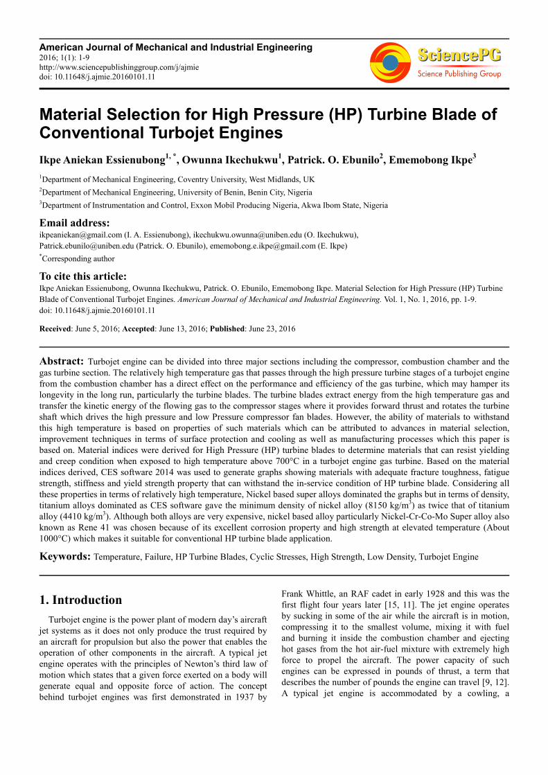
26]. A fan installed in front of the engine helps accelerate air
flow into the first engine compartment where the low
pressure compressor is located. As air is routed by the fan
into the engine a metal cylinder fitted with rectangular blades
widens gradually from front to rare while subjecting the
incoming air to increased pressure as shown in Figure 1.
Figure 1. Typical Compressor Blade of an Aircraft gas turbine engine [20].
In other words, the compressor is fitted with low pressure
and high pressure blades rotating alongside with the shaft
like ceiling fan. Within the short space of time required for
air to travel from the low pressure compressor area to the end
of the high compressor area, air can possibly be compressed
into a space 20 times smaller in size than the intake aperture
[20, 21, 22]. Expanding as it exits the high compressor area,
air enters the combustion chamber, an internal combustion
engine cylinder in which air and fuel mixes together, ignites
and burns. From the compressor, another high air stream
barely passes through the centre of the combustion chamber
without being combusted, while a third stream of air leaving
the compressor is passed outside the combustor for cooling
[5, 22]. During combustion and ignition of the air-fuel
mixture in the combustion chamber, extremely hot volume of
gases are produced, some of which exits the engine through
the exhaust, while some quantity of the hot gases is routed
into the turbine engine. In a typical gas turbine engine, a
single turbine compartment is composed of a disc or hub with
a set of turbine blades mounted on it [10, 13]. Also, the
combustion chamber of a turbojet engine is annular, with an
exit ring installed at the back to control exhaust gas leaving
the system. The gases exiting the combustion chamber are
released at a temperature of about 1700°C, while the shaft
rotates at a speed in excess of 12,000 rpm [17].
In summary, air is compressed through the compressor
stages of the gas turbine engine as it enters through the air
inlet, temperature and pressure of the incoming air increases
while the volume decreases during compressing. Temperature
of the compressed air is further increased as it enters and
expands in the combustion chamber (located between the
turbine stages and compressor stages) where air-fuel mixture
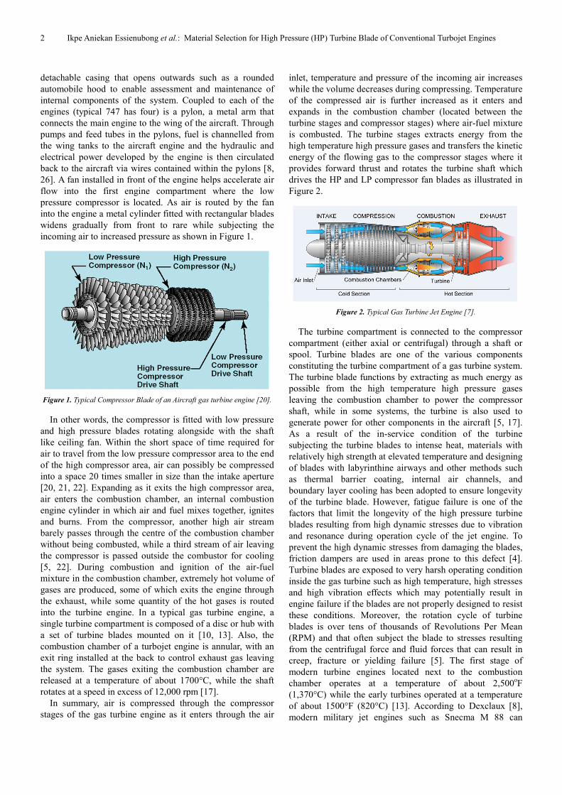
is combusted. The turbine stages extracts energy from the
high temperature high pressure gases and transfers the kinetic
energy of the flowing gas to the compressor stages where it
provides forward thrust and rotates the turbine shaft which
drives the HP and LP compressor fan blades as illustrated in
Figure 2.
Figure 2. Typical Gas Turbine Jet Engine [7].
The turbine compartment is connected to the compressor
compartment (either axial or centrifugal) through a shaft or
spool. Turbine blades are one of the various components
constituting the turbine compartment of a gas turbine system.
The turbine blade functions by extracting as much energy as
possible from the high temperature high pressure gases
leaving the combustion chamber to power the compressor
shaft, while in some systems, the turbine is also used to
generate power for other components in the aircraft [5, 17].
As a result of the in-service condition of the turbine
subjecting the turbine blades to intense heat, materials with
relatively high strength at elevated temperature and designing
of blades with labyrinthine airways and other methods such
as thermal barrier coating, internal air channels, and
boundary layer cooling has been adopted to ensure longevity
of the turbine blade. However, fatigue failure is one of the
factors that limit the longevity of the high pressure turbine
blades resulting from high dynamic stresses due to vibration
and resonance during operation cycle of the jet engine. To
prevent the high dynamic stresses from damaging the blades,
friction dampers are used in areas prone to this defect [4].
Turbine blades are exposed to very harsh operating condition
inside the gas turbine such as high temperature, high stresses
and high vibration effects which may potentially result in
engine failure if the blades are not properly designed to resist
these conditions. Moreover, the rotation cycle of turbine
blades is over tens of thousands of Revolutions Per Mean
(RPM) and that often subject the blade to stresses resulting
from the centrifugal force and fluid forces that can result in
creep, fracture or yielding failure [5]. The first stage of
modern turbine engines located next to the combustion
chamber operates at a temperature of about 2,500oF
(1,370°C) while the early turbines operated at a temperature
of about 1500°F (820°C) [13]. According to Dexclaux [8],
modern military jet engines such as Snecma M 88 can
American Journal of Mechanical and Industrial Engineering 2016; 1(1): 1-9 3
operate up to a temperature level of about 2,900°F (1,590°C).
In addition to the turbine engine operating temperatures,
Rolls Royce [20] reported that the 5th
stage of the low
pressure turbine operates at a temperature of about 900°C,
while the 1st stage intermediate pressure turbine operates at a
temperature of about 1200°C and the 1st stage high pressure
turbine operates at a temperature of about 1500°C
respectively. This high temperature operation can weaken
and limit the performance of the turbine blades as well as the
turbine engine itself, thereby making them more prone to
creep and corrosion failure, while vibrations and resonances
in the turbine engine can result in fatigue failure [3]. The
High Pressure (HP) turbine is exposed to the most intensed
air pressure while the Low Pressure (LP) turbine is exposed
to mild (cooler) lower air pressure. Difference in operating
condition of the HP and LP turbine has resulted in the design
of HP and LP turbine blades which are greatly different in
material and cooling options despite the same
thermodynamic and aerodynamic principles [10]. One of the
major limitations in the early jet engines was the poor
performance of materials used in the high temperature high
pressure areas (combustion chamber and turbine) of the
engine. Consequently, the need for better materials to
eliminate these flaws necessitated further research in the field
of alloys and manufacturing processes and that spurred
researchers in this area of interest to unravel the challenges
which lead to a long list of new materials and techniques that
added more improvement to the modern turbine engines [6,
13, 17]. For example, development and adoption of super
alloys in aircraft applications in 1940s and new
manufacturing techniques such as vacuum induction melting
(involves the application of electric currents in melting
metals within a vacuum) in 1950s significantly improved the
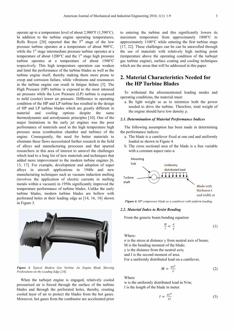
temperature performance of turbine blades. Unlike the early
turbine blades, modern turbine blades are hollow with
perforated holes at their leading edge as [14, 16, 18] shown
in Figure 3.
Figure 3. Typical Modern Gas Turbine Jet Engine Blade Showing
Perforations on the Leading Edge [24].
When the turbojet engine is engaged, relatively cooled
pressurised air is forced through the surface of the turbine
blades and through the perforated holes, thereby, creating
cooled layer of air to protect the blades from the hot gases.
Moreover, hot gases from the combustor are accelerated prior
to entering the turbine and this significantly lowers its
maximum temperature from approximately 1800°C to
approximately 1100°C while entering the first turbine stage
[17, 22]. These challenges can be can be unravelled through
the use of materials with relatively high melting point
(temperature above the operating condition of the turbojet
gas turbine engine), surface coating and cooling techniques
which are the areas that will be addressed in this paper.
2. Material Characteristics Needed for
the HP Turbine Blades
To withstand the aforementioned loading modes and
operating conditions, the material must:
a. Be light weight so as to minimize both the power
needed to drive the turbine. Therefore, total weight of
the engine should have low density ρ.
2.1. Determination of Material Performance Indices
The following assumption has been made in determining
the performance indices:
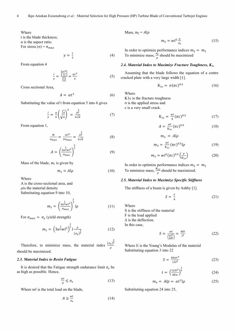
a. The blade is a cantilever fixed at one end and uniformly
loaded as shown in Figure 4.
b. The cross sectional area of the blade is a free variable
with a constant aspect ratio α
Figure 4. HP compressor blade as a cantilever with uniform loading.
2.2. Material Index to Resist Bending
From the generic beam bending equation
�
��
�
� (1)
Where:
σ is the stress at distance y from neutral axis of beam;
M is the bending moment of the blade;
y is the distance from the neutral axis;
and I is the second moment of area.
For a uniformly distributed load on a cantilever,
� � �
� (2)
Where
w is the uniformly distributed load in N/m;
� is the length of the blade in meter.
� ���
�� (3)
4 Ikpe Aniekan Essienubong et al.: Material Selection for High Pressure (HP) Turbine Blade of Conventional Turbojet Engines
Where
t is the blade thickness;
α is the aspect ratio.
For stress (σ) = σ���
� � �� (4)
From equation 4
�� = ����
� ���� = ���
� (5)
Cross sectional Area,
= !"� (6)
Substituting the value of t from equation 5 into 6 gives
�� = �
� #$%�&
'= %�
�√� (7)
From equation 1,
��)*+ = �
��)*+ = %��√� (8)
= #'����)*+ &
� (9)
Mass of the blade, m1 is given by
,� = �- (10)
Where
A is the cross-sectional area, and -is the material density
Substituting equation 9 into 10,
,� = #'����)*+ &
� �- (11)
For .��� = .� (yield strength)
,� = /3!�1��2
� � 3
4�56� (12)
Therefore, to minimize mass, the material index 4�56�
3
should be maximized.
2.3. Material Index to Resist Fatigue
It is desired that the Fatigue strength endurance limit .7 be
as high as possible. Hence,
�% ≤ .7 (13)
Where 1� is the total load on the blade,
≥ ��: (14)
Mass, m2 = �-
,� = 1�� 3�: (15)
In order to optimize performance indices ,� = ,�
To minimize mass, �:3 should be maximized
2.4. Material Index to Maximize Fracture Toughness, K1c
Assuming that the blade follows the equation of a centre
cracked plate with a very large width [1].
K�< = .=>[email protected] (16)
Where
K1c is the fracture toughness
σ is the applied stress and
c is a very small crack.
K�< = �% =>[email protected] (17)
= �D�E =>[email protected] (18)
,' = �-
,' = �D�E =>[email protected]�- (19)
,' = 1��=>[email protected] / 3D�E2 (20)
In order to optimize performance indices ,' = ,�
To minimize mass, D�E
3 should be maximized.
2.5. Material Index to Maximize Specific Stiffness
The stiffness of a beam is given by Ashby [1].
F = G∆ (21)
Where
S is the stiffness of the material
F is the load applied
∆ is the deflection.
In this case,
F = �IJK�
LMNO = PQ� (22)
Where E is the Young’s Modulus of the material
Substituting equation 3 into 22
F = PQ����� (23)
" = /��RPQ� 2
�� (24)
,S = �T = !"��- (25)
Substituting equation 24 into 25,
American Journal of Mechanical and Industrial Engineering 2016; 1(1): 1-9 5
,S = ! /��RPQ� 2
� �- (26)
,S = √! /��RP 2
� � I 3
Q�O (27)
In order to optimize performance indices ,S = ,�
Therefore to minimize mass, Q�3 should be maximized.
2.6. Material Index to Maximize Natural Frequency
The natural frequency of a body is given by Ashby [1].
U = ��V $/W
�2 (28)
Where K is the stiffness constant and is given by
X = %Q (29)
, = �- (30)
Substituting equation 29 and 30 into 28 yields
U = ��V $/ %Q
%32 (31)
U = ��V �$/Q
32 (32)
To maximize natural frequency, /Q32A.C
should be
maximized.
The material indices to be maximized are
Q�3 , /D�E
3 2 , �:3 , 4�56�
3 , /Q32A.C
respectively
2.7. Selection of Material
Newer and more powerful aircraft engines are being
developed in order to increase efficiencies. The air at the high
pressure compression chamber is being compressed further
resulting in increased temperature and pressure of the high
pressure compression chamber. For engines such as the Rolls
Royce Trent series and CMF’s Leap X, the temperature at the
end of the compression process can exceed 1300°C [21].
These temperatures are clearly above the service temperature
capabilities of Titanium alloy which is about 600°C and Steel
and its alloys which are about 450°C. Also, at relatively high
temperature above 600°C, the protective oxide layer on the
surface of Titanium alloy reacts with oxygen and carbon,
thereby, causing it to be very hard and brittle in nature [19].
From the information gathered from relevant literatures, the
in-service condition of turbojet engine gas turbine blades
operates at relatively higher temperature than that of HP and
LP compressor blades of the same engine. To meet the
demands of these more powerful engines, materials which
are capable of withstanding the harsh service environment
are used. The desired material characteristics include;
a. The material should have high service temperature
(700°C and above) in order to withstand the high
temperature environment.
b. Low Coefficient of thermal expansion α in order to keep
strain and thermal stresses as low as possible
c. High fracture toughness K1c to resist initiation and
propagation of cracks.
d. Low density ρ so as to minimize both the power needed
to drive the compressor and the total weight of the
engine
e. Should have high fatigue strength σe in order to
withstand many cycles of fluctuating loads
f. Be able to withstand tensile and bending stresses and
hence should have high value of Young’s Modulus and
high yield strength σy
g. The natural frequency of the material should be high so
as not to be excited into resonance.
h. The material should be erosion and corrosion resistant.
2.7.1. Material Index to Resist Bending
In order to resist bending at minimum mass, the material
index 4�56�
3 should be maximized.
2.7.2. Material Index to Resist Fatigue
To resist fatigue at minimum mass, the quantity �:3 should
be maximized.
2.7.3. Material Index to Maximize Fracture Toughness, K1c
To maximize fracture toughness while keeping mass to its
minimum, /W�Z3 2 should be maximized.
2.7.4. Material Index to Maximize Specific Stiffness
It was derived that to maximize specific stiffness, Q�3
should be maximized.
2.7.5. Material Index to Maximize Natural Frequency
It was also derived that to maximize the natural frequency,
/Q32A.C
should be maximized.
3. Methodology
CES Edupack software is a material selection tool that is
made up of level 1, 2 and 3 and level 2 consist of more
materials than level 1, while level 3 contains more materials
than level 2. Based on the above material selection
requirements and materials indices to be maximised, a search
was carried out using CES software Level 3 to determine
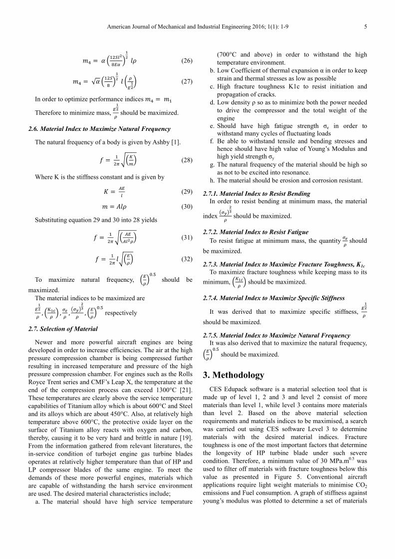
materials with the desired material indices. Fracture
toughness is one of the most important factors that determine
the longevity of HP turbine blade under such severe
condition. Therefore, a minimum value of 30 MPa.m0.5
was
used to filter off materials with fracture toughness below this
value as presented in Figure 5. Conventional aircraft
applications require light weight materials to minimise CO2
emissions and Fuel consumption. A graph of stiffness against
young’s modulus was plotted to determine a set of materials
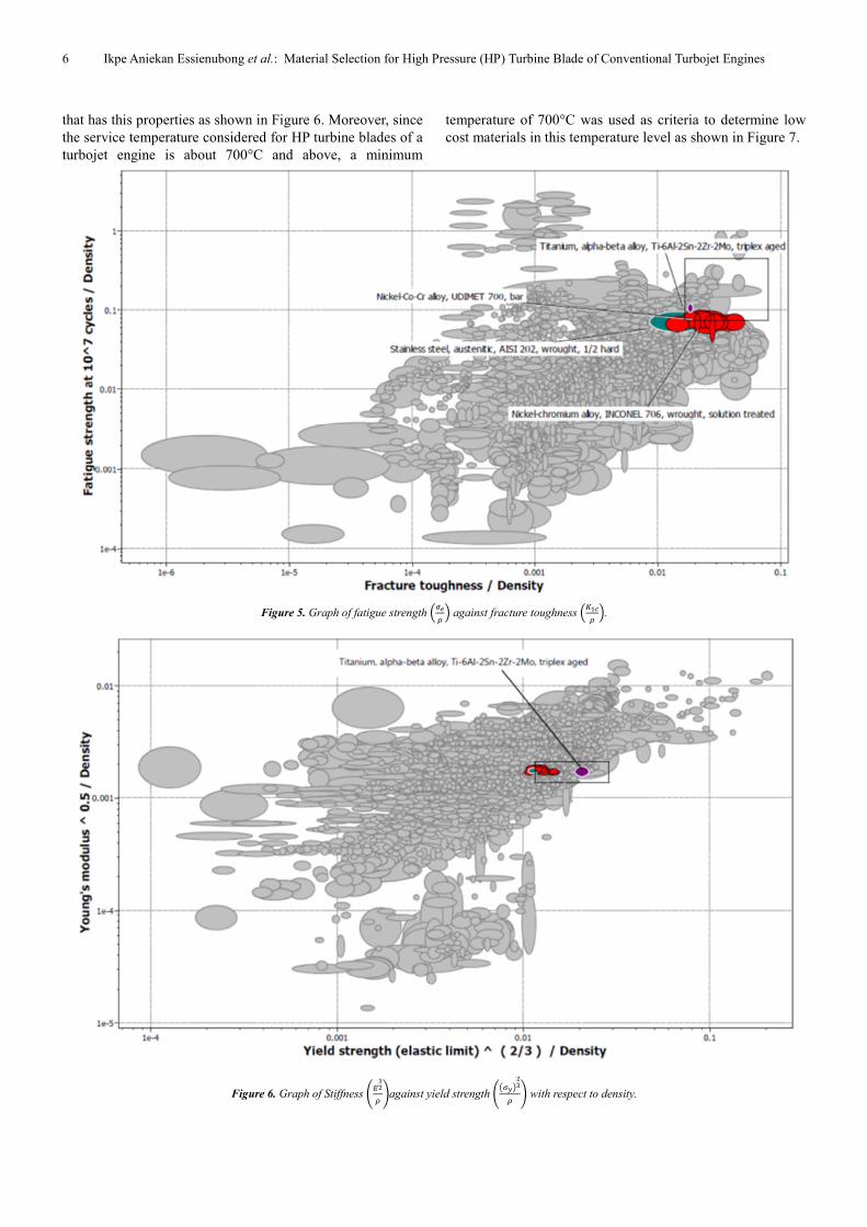
6 Ikpe Aniekan Essienubong et al.: Material Selection for High Pressure (HP) Turbine Blade of Conventional Turbojet Engines
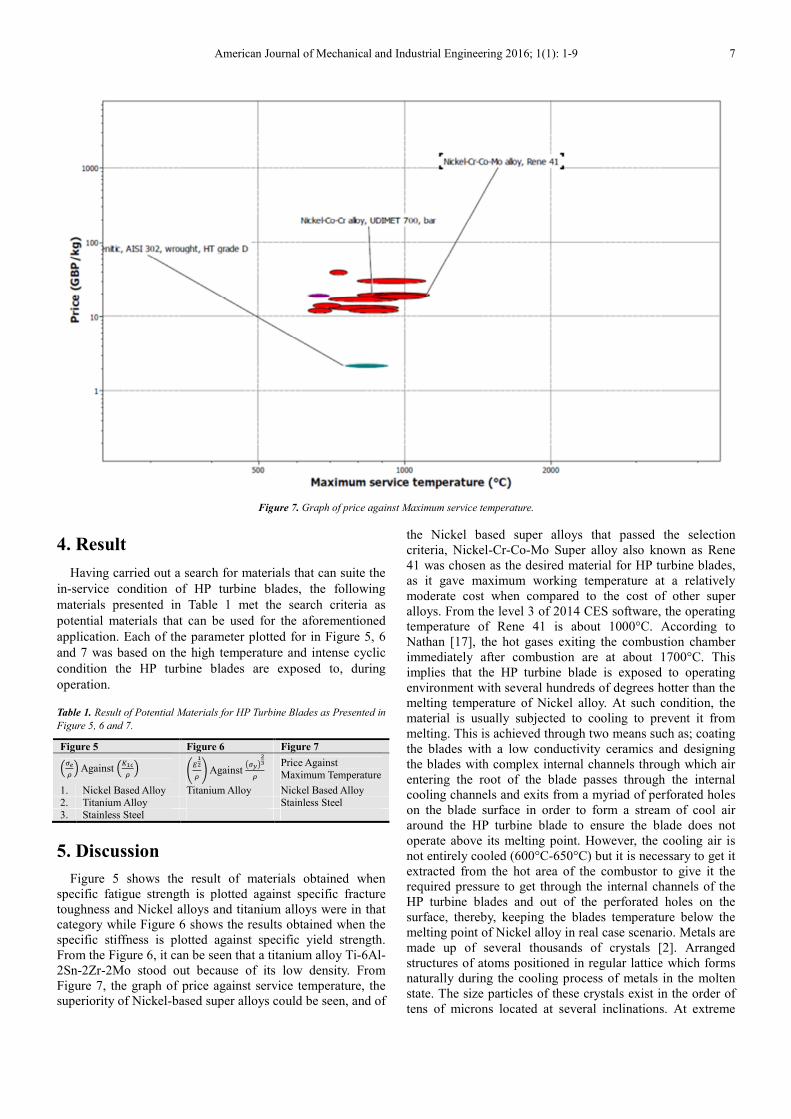
that has this properties as shown in Figure 6. Moreover, since
the service temperature considered for HP turbine blades of a
turbojet engine is about 700°C and above, a minimum
temperature of 700°C was used as criteria to determine low
cost materials in this temperature level as shown in Figure 7.
Figure 5. Graph of fatigue strength /�:3 2 against fracture toughness /W�Z
3 2.
Figure 6. Graph of Stiffness #Q�3 &against yield strength #4�56�
3 & with respect to density.
American Journal of Mechanical and Industrial Engineering 2016; 1(1): 1-9 7
Figure 7. Graph of price against Maximum service temperature.
4. Result
Having carried out a search for materials that can suite the
in-service condition of HP turbine blades, the following
materials presented in Table 1 met the search criteria as
potential materials that can be used for the aforementioned
application. Each of the parameter plotted for in Figure 5, 6
and 7 was based on the high temperature and intense cyclic
condition the HP turbine blades are exposed to, during
operation.
Table 1. Result of Potential Materials for HP Turbine Blades as Presented in
Figure 5, 6 and 7.
Figure 5 Figure 6 Figure 7
/�:3 2 Against /W�Z
3 2 #Q�3 & Against
4�56�3
Price Against
Maximum Temperature
1. Nickel Based Alloy Titanium Alloy Nickel Based Alloy
2. Titanium Alloy Stainless Steel
3. Stainless Steel
5. Discussion
Figure 5 shows the result of materials obtained when
specific fatigue strength is plotted against specific fracture
toughness and Nickel alloys and titanium alloys were in that
category while Figure 6 shows the results obtained when the
specific stiffness is plotted against specific yield strength.
From the Figure 6, it can be seen that a titanium alloy Ti-6Al-
2Sn-2Zr-2Mo stood out because of its low density. From
Figure 7, the graph of price against service temperature, the
superiority of Nickel-based super alloys could be seen, and of
the Nickel based super alloys that passed the selection
criteria, Nickel-Cr-Co-Mo Super alloy also known as Rene
41 was chosen as the desired material for HP turbine blades,
as it gave maximum working temperature at a relatively
moderate cost when compared to the cost of other super
alloys. From the level 3 of 2014 CES software, the operating
temperature of Rene 41 is about 1000°C. According to
Nathan [17], the hot gases exiting the combustion chamber
immediately after combustion are at about 1700°C. This
implies that the HP turbine blade is exposed to operating
environment with several hundreds of degrees hotter than the
melting temperature of Nickel alloy. At such condition, the
material is usually subjected to cooling to prevent it from
melting. This is achieved through two means such as; coating
the blades with a low conductivity ceramics and designing
the blades with complex internal channels through which air
entering the root of the blade passes through the internal
cooling channels and exits from a myriad of perforated holes
on the blade surface in order to form a stream of cool air
around the HP turbine blade to ensure the blade does not
operate above its melting point. However, the cooling air is
not entirely cooled (600°C-650°C) but it is necessary to get it
extracted from the hot area of the combustor to give it the
required pressure to get through the internal channels of the
HP turbine blades and out of the perforated holes on the
surface, thereby, keeping the blades temperature below the
melting point of Nickel alloy in real case scenario. Metals are
made up of several thousands of crystals [2]. Arranged
structures of atoms positioned in regular lattice which forms
naturally during the cooling process of metals in the molten
state. The size particles of these crystals exist in the order of
tens of microns located at several inclinations. At extreme

8 Ikpe Aniekan Essienubong et al.: Material Selection for High Pressure (HP) Turbine Blade of Conventional Turbojet Engines
temperature and under the influence of stresses and strains,
the crystals can potentially slide against one another and
impurities can possibly move towards the grain boundaries.
This phenomenon is known as creep, a failure mode that
greatly affected the early turbine blades which were
manufactured from steel through forging. To reduce the
effect of creep, super alloys with solid solution strengthening,
grain boundary strengthening as well as thermal barrier
coatings are applied in HP turbine blade design and
manufacturing process. The application of protective coatings
which are usually stabilized zirconium dioxide-based ceramic
is to ensure the reduction of thermal damage and to control
oxidation. The use of thermal protective coating limits the
high temperature subjection of Nickel super alloy and this in
turn reduces the creep mechanism the blade is exposed to.
However, oxidation coatings minimises efficiency losses due
to build-up of heat on the external part of the blade. Apart
from using protective coatings, some manufacturing
techniques such as hot isostatic pressing, a process used for
reducing the porosity of metals can be used to improve alloys
used for manufacturing HP turbine blade as well as its
performance. Furthermore, the evolution of Directional
Solidification (DS) and Single Crystal (SC) production
techniques has played a vital role in increasing the strength of
HP turbine blade alloys against the effects of creep and
fatigue as DS functions by orienting grain boundaries in one
direction while SC eradicates the grain boundaries [13].
Another method of improving turbine blades is through
cooling which can be achieved through air or liquid.
Although liquid cooling seems more attractive due to high
specific heat capacity and partials of evaporative cooling,
liquid cooling has some disadvantages such as corrosion,
leakage, choking etc. whereas, air cooling allows the flow of
air into hot areas in the turbine blades without any problem.
At the early stage of jet engines, the prototypes of Frank
Whittles were manufactured entirely from steel which best
known for strength and surface hardness [17], but its
unsuitability necessitated the search materials that can
withstand high temperature and jet engine manufacturers
turned to Nickel alloy which does not only exhibit high
resistance against corrosion and cyclic stresses, but has an
outstanding characteristics referred to as gamma prime in
which Nickel combines with aluminium to maintain its
strength at extreme temperature conditions. Nickel alloy is
composed of austenitic-face-centred cubic (fcc) matrix phase
(γ) (with each cube comprising a face with five atoms, one at
the centre and one at each corner) and a variety of other
phases such as gamma prime (γ'), M6C, carbides MC and
M23C6, of which the γ' heightens and sustains the increased
strength at extreme temperature condition. The atoms present
in Nickel alloys can swap in and out of the fcc lattice, but
under the right composition of aluminium and Nickel, Nickel
migrates to the centre of the faces and aluminium at the
corners. This is called precipitate, in which half a micron (in
size) of alloys are closely packed together and under this
condition, a single atom of dislocation cannot easily slip or
move through it, therefore the cuboids of γ’ in the matrix pins
every possible dislocation movement in position and causing
difficulty in the metal deformation when exposed to high
temperature or cyclic stresses caused by vibration of the
rotating HP turbine jet. During manufacturing, Molybdenum
is added to the γ' phase of Ni base alloys as strengtheners at
both room and elevated temperatures [25]. Aluminium
improves the protective surface oxide film, while addition of
niobium, titanium and carbide formers is used to stabilize the
alloys against the effect of chromium-carbide sensitization.
Addition of small quantity of chromium (8%) to nickel
impacts resistance to heat by creating a surface film of Cr2O3
as well as increasing the nickel chromium alloy sensitivity to
oxidation and corrosion resistance rate. Although Rene 41
super alloy (alongside other nickel based super alloys) seems
to be the conventional material for HP turbine blades, its
density which is in the range of 8150-8350 kg/m3, (about
twice the density of Titanium alloys) is a major drawback for
HP turbine blades. Also, the cost of super alloy and its
processing is relatively high [23]. Moreover, other materials
such as Ceramics and Ceramic Matrix Composites, Polymers
and Polymer matrix composites etc. have been proven
suitable for the manufacturing of HP turbine blades, their
application in this area is very minimal and still undergoing
development. Finally, the last stages of the turbine rotor
blades and sometimes the stator blades (exposed to minimal
or no stresses) of a jet engine are less exposed to creep
effects and are not required to be manufactured with Nickel
based super alloys.
6. Conclusion
This paper review focused on material selection processes
for conventional material for the HP turbine blade of a
turbojet engine. The primary aim was to determine materials
that can withstand the service temperature of high pressure
turbine blade of a turbojet engine which for decades
subjected HP turbine blades of early turbojet engines to creep
and cyclic stresses due to centrifugal forces acting on the
blade component. The choice of material chosen satisfied the
operating condition of HP turbine blades in terms of high
strength at relatively high temperature.
References
[1] Ashby M. F. (1992) Materials Selection in Mechanical Design. Oxford: Pergamon Press
[2] Avnir, D. (2014) Molecular Doped Metals. Account of Chemical Research 47: 579-94. PMID 24283194
[3] Bhagi, L. K., Rastogi, V., Gupta, P. (2013) Fractographic Investigations of the Failure of L-1 Low Pressure Steam Turbine Blade. Case Study in Engineering Failure Analysis, 1 (2) 72-87
[4] Bhagi, L. K., Rastogi, V., Gupta, P. (2012) A brief Review on Modelling Approaches of Friction Dampers used in Turbo Machinery. Advances in Intelligence and Soft Computing 131: 317-329
[5] Boyce, M. (2006) Gas Turbine Engineering Handbook. Oxford, UK: Elsevier Butterworth-Heinemann
American Journal of Mechanical and Industrial Engineering 2016; 1(1): 1-9 9
[6] Campbell, F. (2006) Manufacturing Technology for Aerospace Structural Material. London: Elsevier Ltd
[7] Dahl, J. (2007) Diagram of a Typical Gas Turbine Jet Engine. Wikimedia Commons. [online] available from <https://commons.m.wikimedia.org/wiki/File:Jet_engine.svg> [26 May 2016]
[8] Dexclaux, J. and Serre, J. (2003) M 88-2-E 4: Advanced New Generation Engine for Rafale Multirole Fighter /ICAS International Air and Space Symposium and Exposition: The Next 100 Years. 4-14 July 2003, Dayton, Ohio. AIAA 2003-2722
[9] Eckardt, D. and Rufli, P. (2002) Advanced Gas Turbine Technology. ABB/BBC Historical Firsts. ASME J. Eng Gas Turbine Power pp 124, 542-549
[10] Flack, R. (2005) Fundamental of Jet Propulsion with Applications. Chapter 8: Axial Flow Turbines. Cambridge Aerospace Series. New York, NY: Cambridge University Press. ISBN: 978-0-521-81983-1
[11] Golley, J. (1996) Jet: Frank Whittle and the invention of the Jet Engine. ISBN: 978-1-907472-00-8
[12] Kamps, T. (2005) Model Jet Engines. Traplet Publications. ISBN: 1-900371-91-X
[13] Koff, B. L. (2003) Gas Turbine Technology Overview-A Design’s Perspective. AIAA/ICAS International Air and Space Symposium and Exposition: The Next 100 Years. 4-14 July 2003, Dayton, Ohio. AIAA 2003-2722
[14] Mackay, R. A., Gabb, T. P., Smialek, J. L. and Nathal, M. V. (2010) A New Approach of Designing Super Alloys for Low Density. Springer, Journal of the Minerals, Metals and Materials Society 62 (1) 48-54
[15] Materials World Magazine (2013) Materials through the Ages: Materials for Aeroplane Engines. The Institute of Materials, Minerals and Mining, London, United Kingdom. [online] available from <http://www.iom3.org/materials-world-magazine/feature/2013/may/09/materials-through-ages-materials-aeroplane-engines> [27 May 2016]
[16] Muhlbauer, A. (2008) History of Induction Heating and Melting. ISBN: 978-3-8027-2946-1
[17] Nathan, S. (2015) Jewel in the Crown: Rolls-Royce’s Single-Crystal Turbine Blade Casting Foundry. [online] available <from https://www.theengineer.co.uk/issues/june-2015-online/jewel-in-the-crown-rolls-royces-single-crystal-turbine-blade-casting-foundry/> [2 August 2015]
[18] Nayan, N., Govind, Saikrishna, C. N., Ramaiah, K., Venkata, Bhaumik, S. K., Nair. K. S. and M. C. (2007) Vacuum Induction Melting of Ni Ti Shape Memory Alloys in Graphite Crucible. Material Science and Engineering: A 465: 44
[19] Princeton University (2000) Oxidation of a polycrystalline titanium surface by oxygen and water [online] available from <http://www.princeton.edu/~jsgroup/science167.pdf> [10 March 2014]
[20] Rolls Royce (2007) Selection of Materials for Aerospace Systems. [online] available from <http://www.rolls royce.com/about/technology/gas_turbine_tech/introduction.jsp> [29 January 2014]
[21] Rolls Royce (2014) Compressors [online] available from <http://www.rolls-royce.com/about/technology/gas_turbine_tech/compressors.jsp>[13 March 2014]
[22] Stack Exchange Inc (2016) Why are Turbine Blades not made out of Titanium alloys, only Compressor Blades. [online] available from <http://aviation.stackexchange.com/questions/11481/why-are-turbine-blades-not-made-out-of-titanium-only-compressor-blades> [27 May 2016]
[23] Suranaree University of Technology (2007) Titanium and its alloy [online] available from <http://www.sut.ac.th/engineering/metal/pdf/Nonferrous/05_Titanium%20and%20titanium%20alloys.pdf> [2 April 2014]
[24] Tomeasy (2009) Schematic of a High Pressure gas Turbine Blades of Aircraft Engines. [online] available from <https://commons.m.wikimedia.org/wiki/File:GaTurbineBlade.svg> [27 May 2016]
[25] Walter, J. L., Jackson M. R., and Sims C. T (1988) Alloying. Published: Metal Park, Ohio: ASM International.
[26] Yahya, S. M. (2011) Turbines Compressors and Fans. New Delhe: Tata McGraw-Hill Education. Pp 430-433, ISBN: 9780070707023
Recommended