SCREW THREADS
Presented By:
An Intermediate Level Technical Seminar Covering:
Design, nomenclature,
Acceptability, & gaging
Glastonbury Southern Gage
Written By:
David T. Harris ASQ – CMI, CQT, CQE, CQA ISO Certified Lead Auditor
Corporate Quality Director
GlastonburySouthern Gage / Alpha Q, Inc. [email protected]
© January 2003 Glastonbury Southern Gage All Rights Reserved
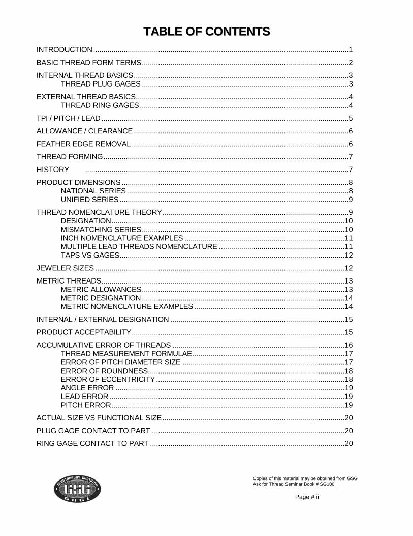
TTAABBLLEE OOFF CCOONNTTEENNTTSS INTRODUCTION..............................................................................................................................1
BASIC THREAD FORM TERMS......................................................................................................2
INTERNAL THREAD BASICS..........................................................................................................3 THREAD PLUG GAGES ......................................................................................................3
EXTERNAL THREAD BASICS.........................................................................................................4 THREAD RING GAGES.......................................................................................................4
TPI / PITCH / LEAD..........................................................................................................................5
ALLOWANCE / CLEARANCE..........................................................................................................6
FEATHER EDGE REMOVAL...........................................................................................................6
THREAD FORMING.........................................................................................................................7
HISTORY ..................................................................................................................................7
PRODUCT DIMENSIONS................................................................................................................8 NATIONAL SERIES .............................................................................................................8 UNIFIED SERIES.................................................................................................................9
THREAD NOMENCLATURE THEORY............................................................................................9 DESIGNATION...................................................................................................................10 MISMATCHING SERIES....................................................................................................10 INCH NOMENCLATURE EXAMPLES ...............................................................................11 MULTIPLE LEAD THREADS NOMENCLATURE ..............................................................11 TAPS VS GAGES...............................................................................................................12
JEWELER SIZES ...........................................................................................................................12
METRIC THREADS........................................................................................................................13 METRIC ALLOWANCES....................................................................................................13 METRIC DESIGNATION....................................................................................................14 METRIC NOMENCLATURE EXAMPLES ..........................................................................14
INTERNAL / EXTERNAL DESIGNATION ......................................................................................15
PRODUCT ACCEPTABILITY.........................................................................................................15
ACCUMULATIVE ERROR OF THREADS .....................................................................................16 THREAD MEASUREMENT FORMULAE...........................................................................17 ERROR OF PITCH DIAMETER SIZE ................................................................................17 ERROR OF ROUNDNESS.................................................................................................18 ERROR OF ECCENTRICITY.............................................................................................18 ANGLE ERROR .................................................................................................................19 LEAD ERROR ....................................................................................................................19 PITCH ERROR...................................................................................................................19
Copies of this material may be obtained from GSG Ask for Thread Seminar Book # SG100
Page # ii
ACTUAL SIZE VS FUNCTIONAL SIZE..........................................................................................20
PLUG GAGE CONTACT TO PART ...............................................................................................20
RING GAGE CONTACT TO PART ................................................................................................20
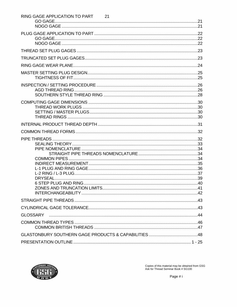
RING GAGE APPLICATION TO PART 21 GO GAGE...........................................................................................................................21 NOGO GAGE .....................................................................................................................21
PLUG GAGE APPLICATION TO PART .........................................................................................22 GO GAGE...........................................................................................................................22 NOGO GAGE .....................................................................................................................22
THREAD SET PLUG GAGES ........................................................................................................23
TRUNCATED SET PLUG GAGES.................................................................................................23
RING GAGE WEAR PLANE...........................................................................................................24
MASTER SETTING PLUG DESIGN...............................................................................................25 TIGHTNESS OF FIT...........................................................................................................25
INSPECTION / SETTING PROCEDURE .......................................................................................26 AGD THREAD RING..........................................................................................................26 SOUTHERN STYLE THREAD RING .................................................................................28
COMPUTING GAGE DIMENSIONS ..............................................................................................30 THREAD WORK PLUGS ...................................................................................................30 SETTING / MASTER PLUGS.............................................................................................30 THREAD RINGS ................................................................................................................30
INTERNAL PRODUCT THREAD DEPTH ......................................................................................31
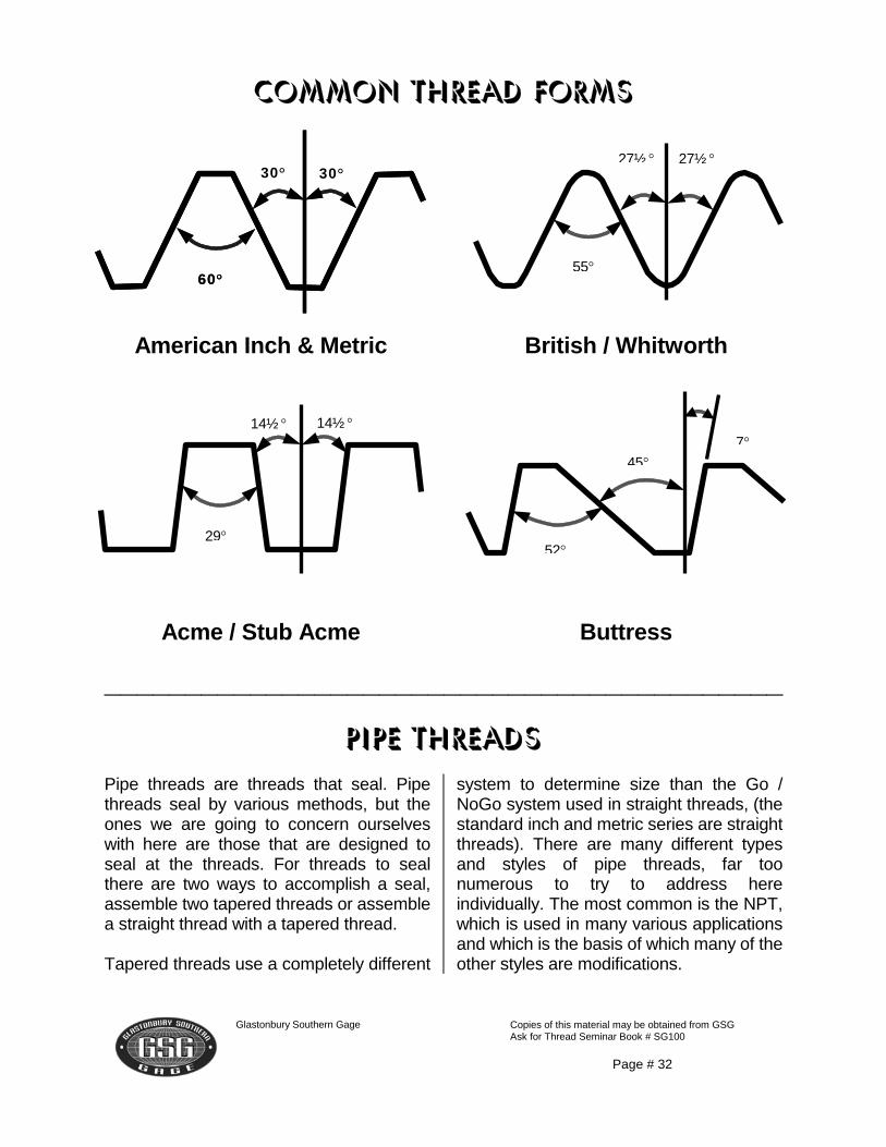
COMMON THREAD FORMS.........................................................................................................32
PIPE THREADS .............................................................................................................................32 SEALING THEORY............................................................................................................33 PIPE NOMENCLATURE ....................................................................................................34 STRAIGHT PIPE THREADS NOMENCLATURE...................................................34 COMMON PIPES ...............................................................................................................34 INDIRECT MEASUREMENT..............................................................................................35 L-1 PLUG AND RING GAGE..............................................................................................36 L-2 RING / L-3 PLUG..........................................................................................................37 DRYSEAL...........................................................................................................................39 6 STEP PLUG AND RING..................................................................................................40 ZONES AND TRUNCATION LIMITS..................................................................................41 INTERCHANGEABILITY....................................................................................................42
STRAIGHT PIPE THREADS ..........................................................................................................43
CYLINDRICAL GAGE TOLERANCE..............................................................................................43
GLOSSARY ................................................................................................................................44
COMMON THREAD TYPES ..........................................................................................................46 COMMON BRITISH THREADS .........................................................................................47
GLASTONBURY SOUTHERN GAGE PRODUCTS & CAPABILITIES ..........................................48
PRESENTATION OUTLINE ..................................................................................................... 1 - 25
Copies of this material may be obtained from GSG Ask for Thread Seminar Book # SG100
Page # i
INTRODUCTION “One of the most common quality problems with threaded products is a lack of knowl-
edge of ‘screw threads.’ This seminar is designed to give a basic understanding of ‘screw
threads’ and ways to inspect them.”
About the Presenters:
David T. Harris
Dave has been with GSG for over 25 years, serving in various capacities including Gage Design, Sales, Engineering, Manufacturing Manager of Cylindrical and Indicating Gages, Software Design, MIS Manager, and presently serving as the Corporate Quality Director. As an active ASME member, Dave is Chairman of the ANSI committee B89.1.6 Measurement of Internal Diameters, as well as
being a member and/or an active participant in several other committees. Dave is a Certified ISO Lead Auditor, and through ASQ is a: (CMI)Certified Mechanical Inspector (CQT)Certified Quality Technician (CQE)Certified Quality Engineer (CQA)Certified Quality Auditor
Michael W. Rose
Mike has been with GSG for over 30 years as an Engineer of Screw Thread Design and Manufacturing of gages and products. As an active ASME member, Mike is Chair-man of the ANSI committees B1.2 “Gages and Gaging For Unified Inch Screw Threads”, and B1.16M “Gages And Gaging For Metric M Screw Threads”, and an active member of
the following committees: B1 main committee for Screw Threads, B1.5 “Acme Screw Threads”, B1.8 “Stub Acme Screw Threads”, and gaging sub-committee member of the American Petroleum Institute. Through ASQ, Mike is a (CMI) Certified Mechanical Inspector
Note: All opinions and interpretations of the ANSI standards are the presenter’s own as
an employee of Glastonbury Southern Gage and not as an ANSI member. The interpretation of the standards is the responsibility of the individual user. Good communications between the user and vendor for a mutual understanding of needs, services, and interpretations of the standards will enhance product quality
Copies of this material may be obtained from GSG Ask for Thread Seminar Book # SG100
Page # 1
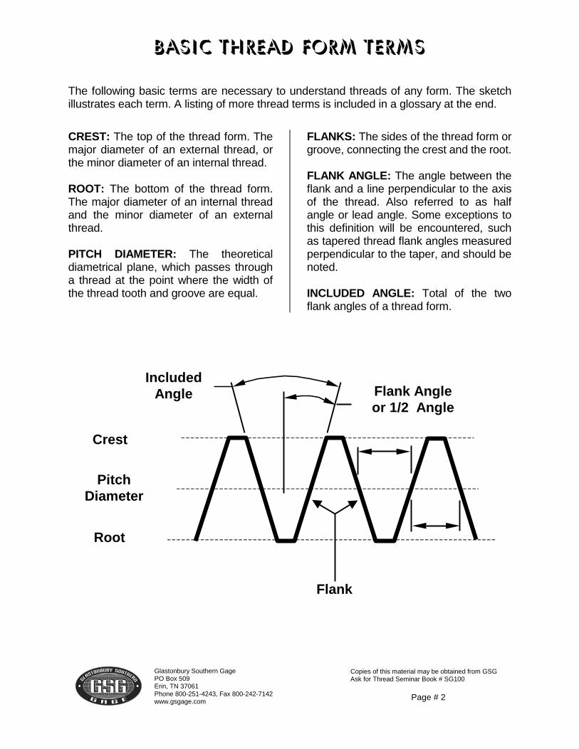
Basic Thread Form Terms The following basic terms are necessary to understand threads of any form. The sketch illustrates each term. A listing of more thread terms is included in a glossary at the end. CREST: The top of the thread form. The major diameter of an external thread, or the minor diameter of an internal thread. ROOT: The bottom of the thread form. The major diameter of an internal thread and the minor diameter of an external thread. PITCH DIAMETER: The theoretical diametrical plane, which passes through a thread at the point where the width of the thread tooth and groove are equal.
FLANKS: The sides of the thread form or groove, connecting the crest and the root. FLANK ANGLE: The angle between the flank and a line perpendicular to the axis of the thread. Also referred to as half angle or lead angle. Some exceptions to this definition will be encountered, such as tapered thread flank angles measured perpendicular to the taper, and should be noted. INCLUDED ANGLE: Total of the two flank angles of a thread form.
Included Angle Flank Angle
or 1/2 Angle
Copies of this material may be obtained from GSG Ask for Thread Seminar Book # SG100
Glastonbury Southern Gage PO Box 509 Erin, TN 37061 Phone 800-251-4243, Fax 800-242-7142 www.gsgage.com Page # 2
Pitch Diameter
Root
Flank
Crest
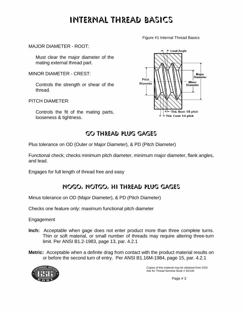
INTERNAL THREAD BASICS
MAJOR DIAMETER - ROOT: Must clear the major diameter of the
mating external thread part. MINOR DIAMETER - CREST: Controls the strength or shear of the
thread. PITCH DIAMETER: Controls the fit of the mating parts,
looseness & tightness.
Figure #1 Internal Thread Basics
GO THREAD PLUG GAGES Plus tolerance on OD (Outer or Major Diameter), & PD (Pitch Diameter) Functional check; checks minimum pitch diameter, minimum major diameter, flank angles, and lead. Engages for full length of thread free and easy
NOGO, NOTGO, HI THREAD PLUG GAGES Minus tolerance on OD (Major Diameter), & PD (Pitch Diameter) Checks one feature only: maximum functional pitch diameter Engagement Inch: Acceptable when gage does not enter product more than three complete turns.
Thin or soft material, or small number of threads may require altering three-turn limit. Per ANSI B1.2-1983, page 13, par. 4.2.1
Metric: Acceptable when a definite drag from contact with the product material results on
or before the second turn of entry. Per ANSI B1.16M-1984, page 15, par. 4.2.1
Copies of this material may be obtained from GSG Ask for Thread Seminar Book # SG100
Page # 3
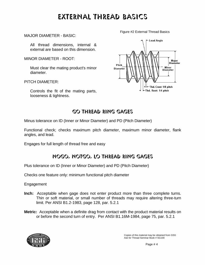
EXTERNAL THREAD BASICS
MAJOR DIAMETER - BASIC: All thread dimensions, internal &
external are based on this dimension. MINOR DIAMETER - ROOT: Must clear the mating product's minor
diameter. PITCH DIAMETER: Controls the fit of the mating parts,
looseness & tightness.
Figure #2 External Thread Basics
GO THREAD RING GAGES Minus tolerance on ID (Inner or Minor Diameter) and PD (Pitch Diameter) Functional check; checks maximum pitch diameter, maximum minor diameter, flank angles, and lead. Engages for full length of thread free and easy
NOGO, NOTGO, LO THREAD RING GAGES Plus tolerance on ID (Inner or Minor Diameter) and PD (Pitch Diameter) Checks one feature only: minimum functional pitch diameter Engagement Inch: Acceptable when gage does not enter product more than three complete turns.
Thin or soft material, or small number of threads may require altering three-turn limit. Per ANSI B1.2-1983, page 128, par. 5.2.1
Metric: Acceptable when a definite drag from contact with the product material results on
or before the second turn of entry. Per ANSI B1.16M-1984, page 75, par. 5.2.1
Copies of this material may be obtained from GSG Ask for Thread Seminar Book # SG100
Page # 4
TTPPII // PPIITTCCHH // LLEEAADD
P L
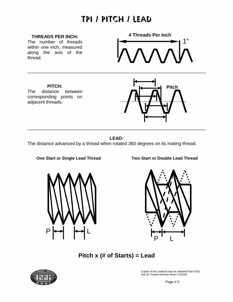
THREADS PER INCH: The number of threads within one inch, measured along the axis of the thread.
__________________________________________
PITCH: The distance between corresponding points on adjacent threads.
__________________________________________
LEAD: The distance advanced by a thread when rotated 360 degrees on its mating thread.
One Start or Single Lead Thread
Two Start or Double Lead Thread
Pitch x (# of Starts) = Lead
Copies of this material may be obtained from GSG Ask for Thread Seminar Book # SG100
Page # 5
4 Threads Per Inch 1”
Pitch
P L
Allowance / Clearance
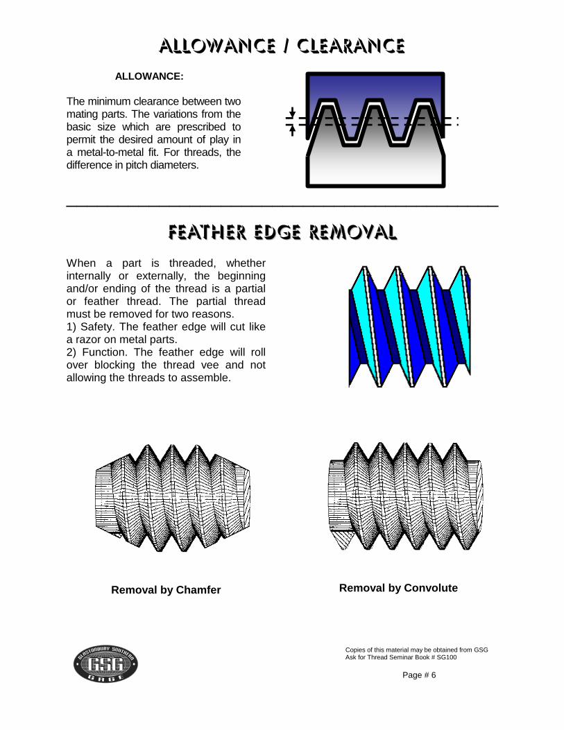
ALLOWANCE: The minimum clearance between two mating parts. The variations from the basic size which are prescribed to permit the desired amount of play in a metal-to-metal fit. For threads, the difference in pitch diameters.
__________________________________________
FFeeaatthheerr EEddggee RReemmoovvaall When a part is threaded, whether internally or externally, the beginning and/or ending of the thread is a partial or feather thread. The partial thread must be removed for two reasons. 1) Safety. The feather edge will cut like a razor on metal parts. 2) Function. The feather edge will roll over blocking the thread vee and not allowing the threads to assemble.
Removal by Chamfer
Removal by Convolute
Copies of this material may be obtained from GSG Ask for Thread Seminar Book # SG100
Page # 6
THREAD FORMING
There are three common methods of creating threads. _________________________________________________________
Tap / Die After the part is formed close to the finished diameter, major diameter for external parts and minor diameter for internal parts, the threads are cut into the part using an instrument that has the thread form on it. Slots or flutes are cut along the axis of the tap or die to create cutting surfaces. The tap or die is screwed into or onto the part, forming the thread. Roll Like the tap / die method, the part is formed close to the finished diameter, but with the diameters controlled for the rolling process. Thread rolls are applied to the parts with intense pressure causing the material to be displaced by the roll’s thread form and extruded into the valley between the roll’s threads,
forming the thread on the part. Single-point This method is used in most lathe thread forming processes. A single cutter with the form of the thread is forced against the part, removing material in a spiral path created by the axial movement of the cutter in combination with the axial turning of the part forming the vee of the thread. Several passes of the cutter may be required to achieve the desire vee depth to form the thread. Plastic and soft material parts are sometimes created by a form or mold. The thread formed or molded is an inverse duplication of the mold thread. The mold thread will usually be created by one of the methods mentioned above.
All threads, regardless of method, must conform to the same criteria. The same gage will check threads made from any method.
__________________________________________
HISTORY
Prior to 1957 the only US Govt. published and recognized product and gage thread dimensions and tolerances, was the American National Series (also known as the National Series). Because of problems and a desire in the manufacturing sector for a better series of standardized threads, the Unified National Series was created and published. The 1957 publication of the government screw thread standard H-28
included this new series of threads (Unified National) along with the National Series. Manufacturers had the option of using either, but were advised to use and/or change over to the new series. This continued with each publication until 1969 when the National Series was dropped from the standard and only the Unified Series was recognized and recommended.
Copies of this material may be obtained from GSG Ask for Thread Seminar Book # SG100
Page # 7
PRODUCT DIMENSIONS
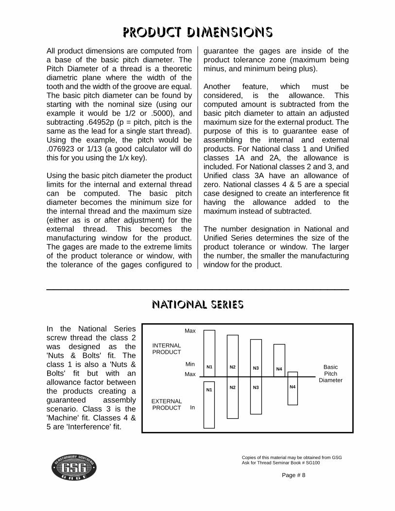
All product dimensions are computed from a base of the basic pitch diameter. The Pitch Diameter of a thread is a theoretic diametric plane where the width of the tooth and the width of the groove are equal. The basic pitch diameter can be found by starting with the nominal size (using our example it would be 1/2 or .5000), and subtracting .64952p (p = pitch, pitch is the same as the lead for a single start thread). Using the example, the pitch would be .076923 or 1/13 (a good calculator will do this for you using the 1/x key). Using the basic pitch diameter the product limits for the internal and external thread can be computed. The basic pitch diameter becomes the minimum size for the internal thread and the maximum size (either as is or after adjustment) for the external thread. This becomes the manufacturing window for the product. The gages are made to the extreme limits of the product tolerance or window, with the tolerance of the gages configured to
guarantee the gages are inside of the product tolerance zone (maximum being minus, and minimum being plus). Another feature, which must be considered, is the allowance. This computed amount is subtracted from the basic pitch diameter to attain an adjusted maximum size for the external product. The purpose of this is to guarantee ease of assembling the internal and external products. For National class 1 and Unified classes 1A and 2A, the allowance is included. For National classes 2 and 3, and Unified class 3A have an allowance of zero. National classes 4 & 5 are a special case designed to create an interference fit having the allowance added to the maximum instead of subtracted. The number designation in National and Unified Series determines the size of the product tolerance or window. The larger the number, the smaller the manufacturing window for the product.
__________________________________________
National SERIES
N1
N1
N2
N2
N3
N4
N3
N4
Basic Pitch
Diameter
Max
Min
Max
MIn
INTERNAL PRODUCT
EXTERNAL PRODUCT
In the National Series screw thread the class 2 was designed as the 'Nuts & Bolts' fit. The class 1 is also a 'Nuts & Bolts' fit but with an allowance factor between the products creating a guaranteed assembly scenario. Class 3 is the 'Machine' fit. Classes 4 & 5 are 'Interference' fit.
Copies of this material may be obtained from GSG Ask for Thread Seminar Book # SG100
Page # 8
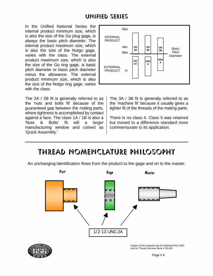
UNIFIED SERIES In the Unified National Series the internal product minimum size, which is also the size of the Go plug gage, is always the basic pitch diameter. The internal product maximum size, which is also the size of the Notgo gage, varies with the class. The external product maximum size, which is also the size of the Go ring gage, is basic pitch diameter or basic pitch diameter minus the allowance. The external product minimum size, which is also the size of the Notgo ring gage, varies with the class.
UN 1B
UN1A
UN 2B
UN2A
UN 3B
UN3
A
Max
Min
Max
MIn
INTERNAL PRODUCT
Basic Pitch
Diameter
EXTERNAL PRODUCT
The 2A / 2B fit is generally referred to as the 'nuts and bolts fit' because of the guaranteed gap between the mating parts, where tightness is accomplished by contact against a face. The class 1A / 1B is also a 'Nuts & Bolts' fit will a larger manufacturing window and coined as 'Quick Assembly.'
The 3A / 3B fit is generally referred to as the 'machine fit' because it usually gives a tighter fit of the threads of the mating parts. There is no class 4. Class 5 was retained but moved to a difference standard more commensurate to its application.
__________________________________________
Thread NOMENCLATURE Philosophy
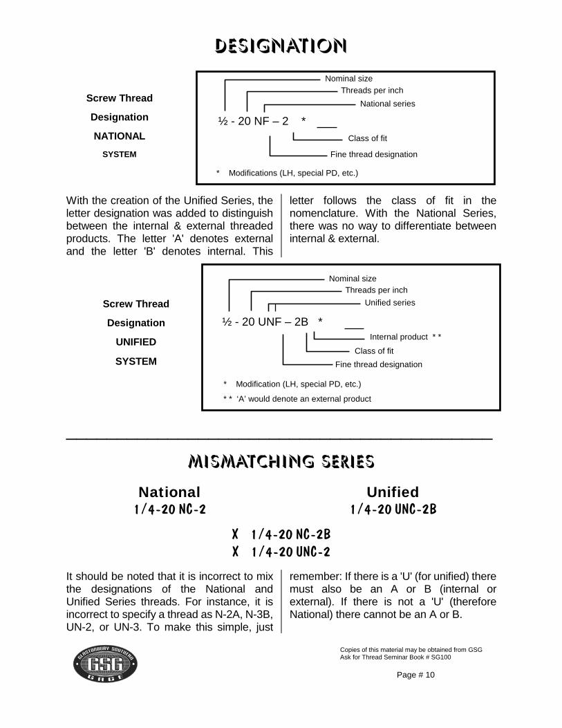
An unchanging identification flows from the product to the gage and on to the master.
Part Gage Master
1/2-13 UNC-2A
Copies of this material may be obtained from GSG Ask for Thread Seminar Book # SG100
Page # 9
DESIGNATION
Screw Thread
Designation
NATIONAL
SYSTEM
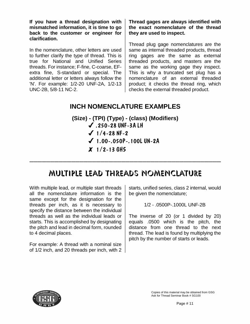
With the creation of the Unified Series, the letter designation was added to distinguish between the internal & external threaded products. The letter 'A' denotes external and the letter 'B' denotes internal. This
letter follows the class of fit in the nomenclature. With the National Series, there was no way to differentiate between internal & external.
__________________________________________
Mismatching Series
National
1/4-20 NC-2 Unified
1/4-20 UNC-2B
X 1/4-20 NC-2B X 1/4-20 UNC-2
It should be noted that it is incorrect to mix the designations of the National and Unified Series threads. For instance, it is incorrect to specify a thread as N-2A, N-3B, UN-2, or UN-3. To make this simple, just
remember: If there is a 'U' (for unified) there must also be an A or B (internal or external). If there is not a 'U' (therefore National) there cannot be an A or B.
Copies of this material may be obtained from GSG Ask for Thread Seminar Book # SG100
Page # 10
½ - 20 NF – 2 *
Nominal size Threads per inch
National series
Class of fit
* Modifications (LH, special PD, etc.)
Fine thread designation
Screw Thread
Designation
UNIFIED
SYSTEM
½ - 20 UNF – 2B *
Nominal size Threads per inch
* Modification (LH, special PD, etc.)
Class of fit Fine thread designation
* * ‘A’ would denote an external product
Internal product * *
Unified series
Glastonbury Southern Gage PO Box 509 Erin, N 37061 Phone 800-251-4243, Fax 800-242-7142 www.gsgage.com
If you have a thread designation with mismatched information, it is time to go back to the customer or engineer for clarification. In the nomenclature, other letters are used to further clarify the type of thread. This is true for National and Unified Series threads. For instance; F-fine, C-coarse, EF-extra fine, S-standard or special. The additional letter or letters always follow the 'N'. For example: 1/2-20 UNF-2A, 1/2-13 UNC-2B, 5/8-11 NC-2.
Thread gages are always identified with the exact nomenclature of the thread they are used to inspect. Thread plug gage nomenclatures are the same as internal threaded products, thread ring gages are the same as external threaded products, and masters are the same as the working gage they inspect. This is why a truncated set plug has a nomenclature of an external threaded product; it checks the thread ring, which checks the external threaded product.
INCH NOMENCLATURE EXAMPLES
(Size) - (TPI) (Type) - (class) (Modifiers) .250-28 UNF-3A LH 1/4-28 NF-2 1.00-.050P-.100L UN-2A
1/2-13 GH5
______________________________________________
MULTIPLE LEAD THREADS nomenclature
With multiple lead, or multiple start threads all the nomenclature information is the same except for the designation for the threads per inch, as it is necessary to specify the distance between the individual threads as well as the individual leads or starts. This is accomplished by designating the pitch and lead in decimal form, rounded to 4 decimal places. For example: A thread with a nominal size of 1/2 inch, and 20 threads per inch, with 2
starts, unified series, class 2 internal, would be given the nomenclature;
1/2 - .0500P-.1000L UNF-2B The inverse of 20 (or 1 divided by 20) equals .0500 which is the pitch, the distance from one thread to the next thread. The lead is found by multiplying the pitch by the number of starts or leads.
Copies of this material may be obtained from GSG Ask for Thread Seminar Book # SG100
Page # 11
TAPs Vs GAGES
A gage size is based on the product tolerance dimensions known, or computable from the standards, based on the nomenclature. A tap size is computed from the basic pitch diameter, adding .0005 times the tap size. Using the product or gage size, the best tap size can be calculated. Using the tap size, the product or gage size cannot be calculated. A product size (nomenclature) specifies a range of dimensions, whereas a tap size only specifies a particular dimension that will fall somewhere within the product range of dimensions.
For instance, using the 1/2-13 example; A tap GH5 would be made to a pitch
diameter of .4525 with a tolerance of minus .0005: [.4500 being the basic pitch diameter, and adding .0005 times 5 or .0025].
{.4500 + (.0005 x 5)} = .4525 A product of UN-2B would be made
to a pitch diameter between .4500 & .4565.
The gages would be made to the tolerance limits of the products, therefore the Go gage would be made to .4500 with a plus tolerance, and the NoGo gage would be made to .4565 with a minus tolerance.
__________________________________________
Jeweler Sizes
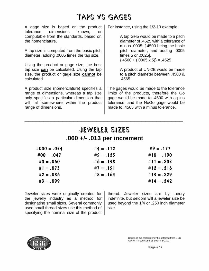
.060 +/- .013 per increment
#000 = .034 #00 = .047 #0 = .060 #1 = .073 #2 = .086 #3 = .099
#4 = .112 #5 = .125 #6 = .138 #7 = .151 #8 = .164
#9 = .177 #10 = .190 #11 = .203 #12 = .216 #13 = .229 #14 = .242
Jeweler sizes were originally created for the jewelry industry as a method for designating small sizes. Several commonly used small thread sizes use this method of specifying the nominal size of the product
thread. Jeweler sizes are by theory indefinite, but seldom will a jeweler size be used beyond the 1/4 or .250 inch diameter size.
Copies of this material may be obtained from GSG Ask for Thread Seminar Book # SG100
Page # 12
6G
6e
6H
6f
6h 6g
Basic Pitch
Diameter
Max
ax
MIn
Min
M
EXTERNAL PRODUCT
INTER AL PRODUCT
N
Basic Pitch
Max
Min
MIn EXTERNAL
L PRODUCT
Diameter
Max
PRODUCT
INTERNA
3h
4h
5h
6h
7h
9h
8h
4H
5H
6H
7H
p is not enough information to clature for the gage or the product is
M
ri s. s to remember about metric threads, is
ta sizee. A proper and complete nomen
ecessary.
een engineered to
product. he metric screw
roduct tolerance or
threads is the opposite of the inch design. With metric screw threads thdesignation for the clroduct tol
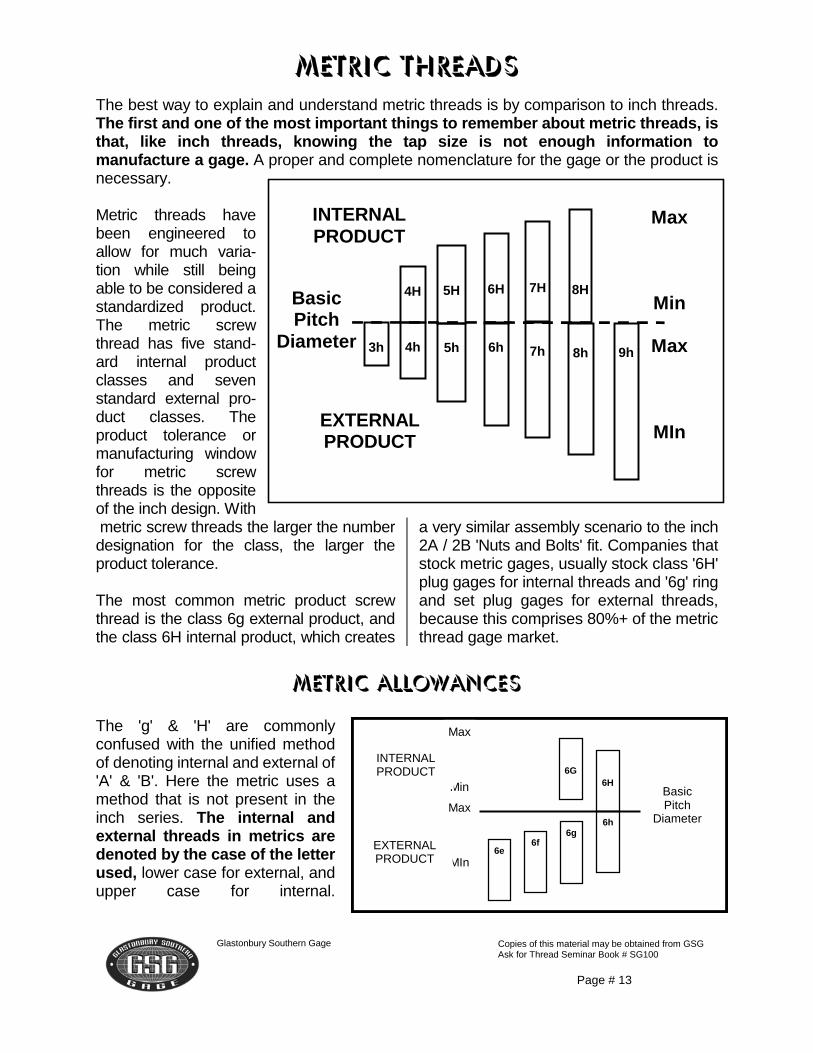
The most common metric product sthread i external product,the clas oduct, which cre
bly scenario to the inch lts' fit. Companies that
etric gages, usually '6H' ages for internal g' ring et plug gages eads, se this comprise ic gage market.
Metric Allowances
he 'g' & 'H' are commonly
enoted by the case of the letter sed, lower case for external, and pper case for internal.
GSG
Ask for Thread Se 100
8H
ETRIC THREADS
The best way to explain and understand metThe first and one of the most important thinthat, like inch threads, knowing the manufacture a gag
c threads is by comparison to inch threadg
n Metric threads have ballow for much varia-tion while still being able to be considered a standardizedTthread has five stand-ard internal product classes and seven standard external pro-duct classes. Thepmanufacturing window for metric screw
e larger the number ass, the larger the
a very similar assem2A / 2B 'Nuts and Bo
p erance.
crew and ss the class 6gs 6H internal pr
and ates
becauthread
stock mplug g
stock class threads and '6
for external thrs 80%+ of the metr
Tconfused with the unified method of denoting internal and external of 'A' & 'B'. Here the metric uses a method that is not present in the inch series. The internal and xternal threads in metrics are e
duu
Copies of this material may be obtained fromminar Book # SG
Glastonbury Southern Gage
Page # 13
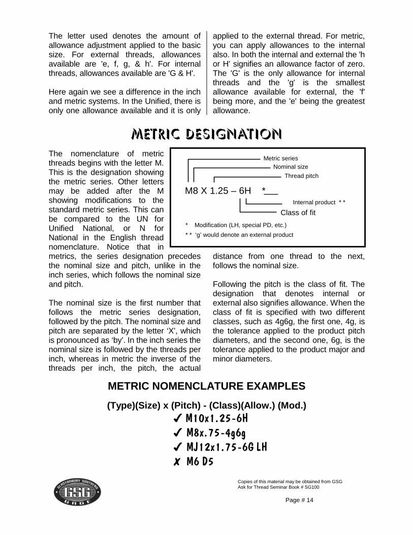
M8 X 1.25 – 6H *
Metric series Nominal size
Th pitread ch
Internal product * *
Class of fit * Modification (LH, special PD, etc.) * * ‘g’ would denote an external product
The letter used denotes tlowance adjustment applied to the basic
we see a difference in the inch nd metric systems. In the Unif
ble a
xternal thread. For metric, you can apply allowances to the internal
allowance available for external, the 'f' being more, and the 'e' being the greatest allowance.
etric DES GNAT O me
e M to the
s canN fo
N forread
that in signation precedes
is pronounced as ‘by’. In thenominal size is followed by
ch, whereas in metric the inverse of the actual
distance from one thread to the next,
oduct pitch , is the
to the product major and minor diameters.
EN RE EXAMPLES itch) - (Cla (Allow.) (Mod.) M10x1.25-6H M 4 g MJ12x1.75-6G LH
M6 D5
CopiesAsk fo
he amount of applied to the ealsize. For external threads, allowances available are 'e, f, g, & h'. For internal threads, allowances available are 'G & H'. Here again
also. In both the internal and external the 'h or H' signifies an allowance factor of zero. The 'G' is the only allowance for internal threads and the 'g' is the smallest
a ied, there is nd it is only only one allowance availa
M
The nomenclature of threads begins with the lettThis is the designation sthe metric series. Other may be added after thshowing modificationsstandard metric series. Thibe compared to the UUnified National, or National in the English thnomenclature. Notice metrics, the series de
I I N
etric r M.
howing letters
r
the nominal size and pitch, unlike in the inch series, which follows the nominal size and pitch. The nominal size is the first number that follows the metric series designation, followed by the pitch. The nominal size and pitch are separated by the letter ‘X’, which
follows the nominal size. Following the pitch is the class of fit. The designation that denotes internal or external also signifies allowance. When the class of fit is specified with two different classes, such as 4g6g, the first one, 4g, is the tolerance applied to the pr
inch series the the threads per
diameters, and the second one, 6gtolerance applied
inthreads per inch, the pitch, the
METRIC NOM(Type)(Size) x (P
CLATU
s )s
8x.75- g6
of this material may be obtained from GSG r Thread Seminar Book # SG100
Page # 14
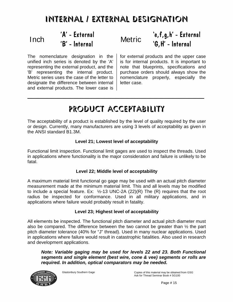
IInntteerrnnaall // EExxtteerrnn
'A’ - External Inch
'B’ - Internal
aall DDeessiiggnnaattiioonn
‘e,f,g,h’ - External Metric
‘G,H’ - Internal
The nomenclature designation in the unified inch series is denoted by the 'A'
for external products and the upper case is for intern
representing the external product, and the 'B' representing theMetric series uses the
gnate the difference between internal s
al products. It is important to note that blueprints, specifications and
uld always show the rly, especially the
letter case.
_______________ _______
T ity
stablished by the level of qua by the user ctu eptability as given in
v a he threads. Used
jo deration and failure is unlikely to be
ve
e ialCUssu
Level 23; Highest level of acceptability
All elements be i diameter must also be compar han ½ the part pitch diameter t lications. Used in applications where failure would fatalities. Also used in research and development applications.
Note: Variable gaging ma nd 23. Both Functional segments and single elem segments or rolls are required. In addition, optical comparators may be needed.
internal product. case of the letter to
purchase orders shonomenclature prope
desiand external products. The lower case i
__________________
PRODUC The acceptability of a product is eor design. Currently, many manufathe ANSI standard B1.3M.
Level 21; Lowest le
Functional limit inspection. Functional limit gin applications where functionality is the mafatal.
______
Acceptabil
lity requiredrers are using 3 levels of acc
el of acceptability
ges are used to inspect t
Level 22; Middle le
A maximum material limit functional go gagmeasurement made at the minimum materto include a special feature. Ex: ½-13 UNradius be inspected for conformance. applications where failure would probably re
r consi
l of acceptability
may be used with an actual pitch diameter limit. This and all levels may be modified -2A (22)(R) The (R) requires that the root ed in all military applications, and in lt in fatality.
nspected. The functional pi ch diameter and actual pitcht
ed. The difference between the two cannot be greater tolerance (40% for “J” any nuclear appthread). Used in m
result in catastrophic
y be used for levels 22 aire, cone & vee)ent (best w
Copies of this material may be obtained from GSG Ask for Thread Seminar Book # SG100
Page # 15
Glastonbury Southern Gage
ACCUMULATIVE ERROR OF THREADS
When inspecti specially p thread ke into a the ror that develops beca eometric intricacy of threads. This accumulative
functional size of thethe geometric eleme
e functional size w
gage, by making er easu s
nal roduct or a gage, by m l size smaller than the measured size.
the functional limits of the product. Pitch mics, wire methods, and
with full profile ultiple ribs, either
ng helical path,
tangent or contacts at the theoretical diaplane of the pitch di
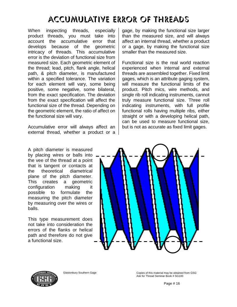
This type measurement
Copies of this material may be obtained from GSG
ng threads, es, you must taroduct
ccount accumulative eruse of the g
error is the deviation of functional size from measured size. Each geometric element of the thread; lead, pitch, flank angle, helical path, & pitch diameter, is manufactured within a specified tolerance. The variation for each element will vary, some being positive, some negative, some bilateral,
Functional size is the real world reaction experienced when internal and external threads are assembled together. Fixed limit gages, which is an attribute gaging system, will measure
from the exact specification. The deviation from the exact specification will affect the
single rib roll indicating instruments, cannot truly measure functional size. Three roll
thread. Depending on nt, the ratio of affect on ill vary.
indicating instruments, functional rolls having mstraight or with a developith
Accumulative error will always affect an external thread, whether a product or a
can be used to measure functional size, but is not as accurate as fixed limit gages.
the functional size largred size, and will alwaythan the m
affect an inter thread, whether a paking the functiona
A pitch diameter is measured by placing wires or balls into the vee of the thread at a point that is
metrical ameter.
This creates a geometric configuration making it possible to formulate the measuring the pitch diameter by measuring over the wires or
alls. b
does not take into consideration the errors of the flanks or helical path and therefore do not give a functional size.
Ask for Thread Seminar Book # SG100
Glastonbury Southern Gage
Page # 16
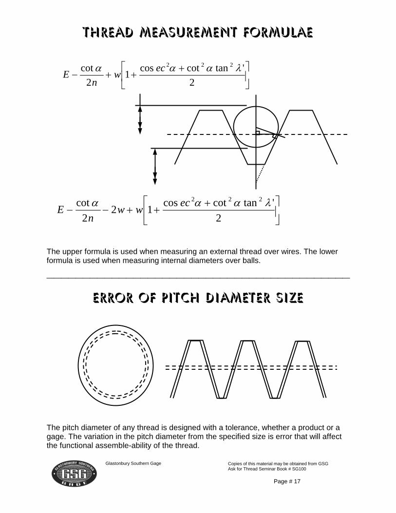
THREAD MEASUREMENT FORMULAE
measuring an external thread over wires. The lower nternal diameters over balls.
__________________________
ITCH DIAMETER SIZE
he pitch diameter of any thread is designed with a tolerance, whether a product or a age. The variation in the pitch diameter from the specified size is error that will affect e functional assemble-ability of the thread.
rom GSG
Ask for Thread Seminar B
The upper formula is used when formula is used when measuring i
________________
ERROR OF P Tgth
Copies of this material may be obtained fook # SG100
Glastonbury Southern Gage
Page # 17
⎥⎤+
2'tancot 22 λα
⎦
⎡ coscot 2αα ec⎢⎣
++−− 122
wwn
E
⎥⎦
⎤'tan 2 λα⎢⎣
⎡ +++−
2cotcos1
2cot 22αα ecw
nE
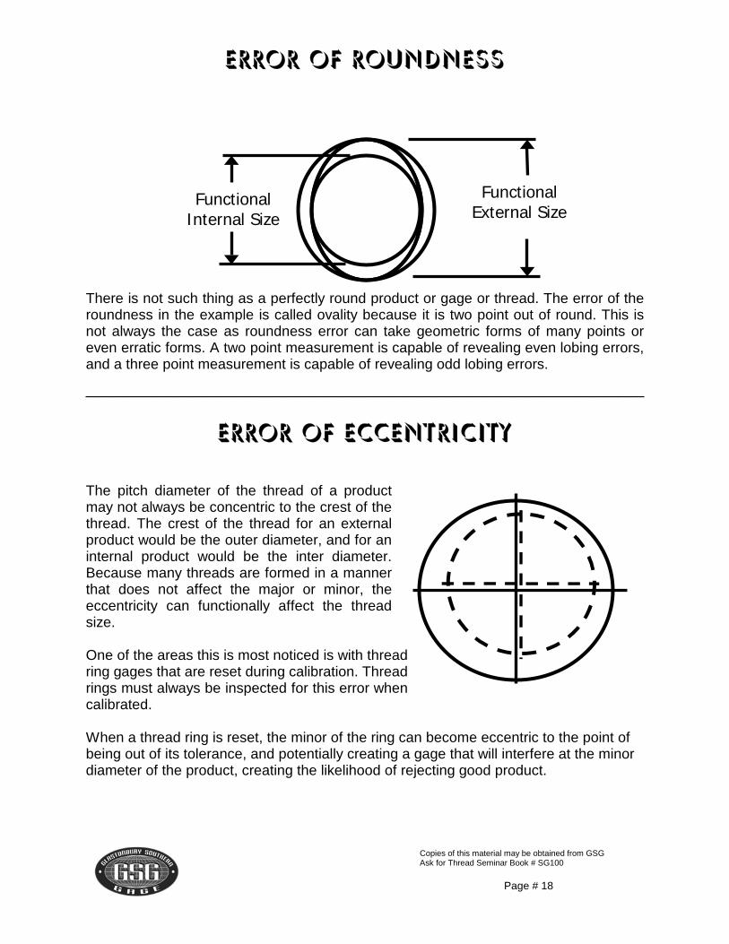
ERROR OF ROUNDNESS There is not such thing as a perfectly round product or gage or thread. The error of the
n the example is called ovality because it is two point out of round. This is ot always the case as roundness error can take geometric forms of many points or ven erratic forms. A two point measurement is capable of revealing even lobing errors, nd a three point measurement is capable of revealing odd lobing errors.
_________________________________________
ERROR OF eccentricity
read. The crest of the thread for an external product woulinternal prod
ecause many threads are formed in a manner at does not affect the major or minor, the
ccentricity can functionally affect the thread ize.
ne of the areas this is most noticed is with thread ng gages that are reset during calibration. Thread ngs must always be inspected for this error when alibrated.
hen a thread ring is reset, the minor of the ring can become eccentric to the point of eing out of its tolerance, and potentially creating a gage that will interfere at the minor iameter of the product, creating the likelihood of rejecting good product.
roundness inea
_
The pitch diameter of the thread of a product may not always be concentric to the crest of the th
d be the outer diameter, and for an uct would be the inter diameter.
Bthes Oriric Wbd
Copies of this material may be obtained from GSG Ask for Thread Seminar Book # SG100
Page # 18
Functional Internal Size
FunctionExternal
al Size
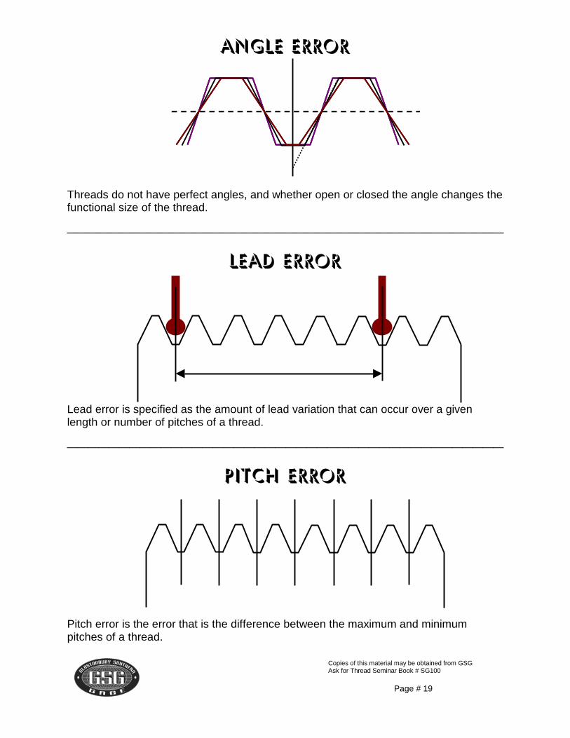
angle error Threads do not have perfect angles, and whether open or closed the angle changes the
onal size of the thread.
on that can occur over a given
__________________
or
itch error is the error that is the difference between the maximum and minimum itches of a thread.
functi
__________________________________________
lead error
Lead error is specified as the amount of lead variatilength or number of pitches of a thread.
________________________
Pitch err Pp
Copies of this material may be obtained from GSG Ask for Thread Seminar Book # SG100
Page # 19
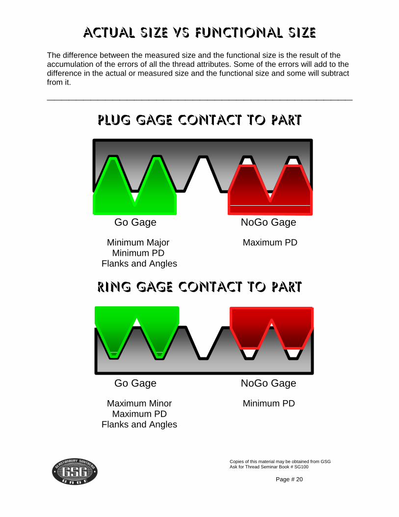
Actual size VS Functional size
he difference between the measured size and the functional size is the result of the ccumulation of the errors of all the thread attributes. Some of the errors will add to the ifference in the actual or measured size and the functional size and some will subtract om it.
_________________________________________
Plug gage contact to part
Go Gage
Minimum Major Minimum PD Flanks and Angles
NoGo Gage Maximum PD
Maximum Minor Maximum PD Flanks and Angles
NoGo Gage Minimum PD
Tadfr
_
ring gage contact to part
Go Gage
Copies of this material may be obtained from GSG Ask for Thread Seminar Book # SG100
Glastonbury Southern Gage PO Box 509 Erin, TN 37061 800-251-4243, Fax 800-242-7142 www.gsgage.com
Page # 20
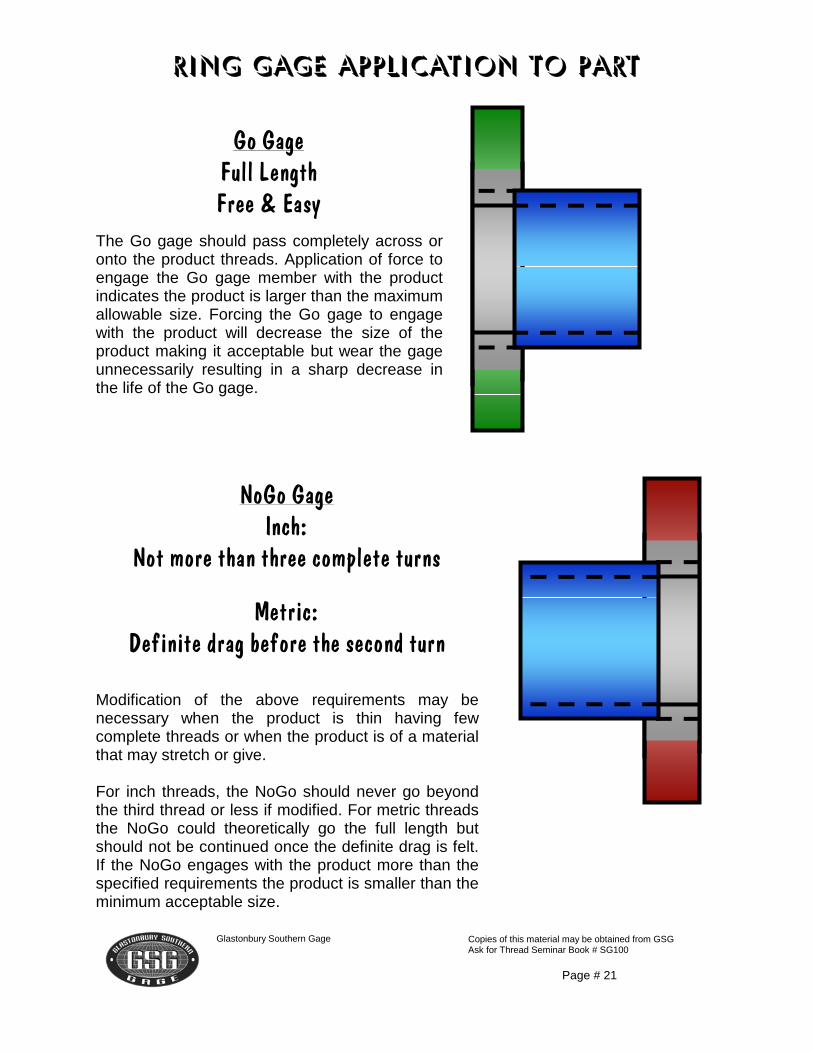
ring gage application to part The Go gage
odungage the Go gage member with the product
cates the product is larger than the maximum llowable size. Forcing the Go gage to engage ith the product will decrease the size of the roduct making it acceptable but wear the gage nnecessarily resulting in a sharp decrease in e life of the Go gage.
odification of the above requirements may be ecessary when the product is thin having few omplete threads or when the product is of a material at may stretch or give.
or inch thre uld never go beyonde thi threa r metric threadse No o co full leng but
hould ot be efinite drag s felt. the N more than the pecified requirements the product is smaller than the inimum acceptable size.
should pass completely across or ct threads. Application of force to onto the pr
eindiawputh
Mncth
ads, the NoGo shoF th rd d or less if modified. Foth G uld theoretically go the
th
s n continued once the d iIf oGo engages with the productsm
Copies of this material may be obtained from GSG Ask for Thread Seminar Book # SG100
Page # 21
Go Gage Full Length Free & Easy
NoGo Gage Inch:
Not more than three complete turns
Metric: Definite drag before the second turn
Glastonbury Southern Gage
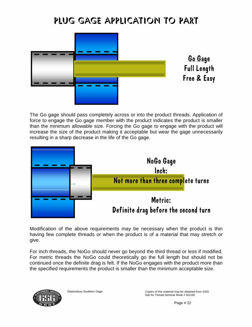
plug gage application to part The Go gage should pass completely across or inforce to engage the Go
Go Gage Full Length Free & Easy
to the product threads. Application of gage member with the product indicates the product is smaller
an the minimum allowable size. Forcing the Go gage to engage with the product will crease the size of the product making it acceptable but wear the gage unnecessarily sulting in a sharp decrease in the life of the Go gage.
ssary when the product is thin when the product is of a material that may stretch or
ive.
e third thread or less if modified. e full length but should not be ages with the product more than e minimum acceptable size.
thinre Modification of the above requirements may be necehaving few complete threads or
NoGo Gage Inch:
Not more than three complete turns
Metric: Definite drag before the second turn
g For inch threads, the NoGo should never go beyond thFor metric threads the NoGo could theoretically go thcontinued once the definite drag is felt. If the NoGo engthe specified requirements the product is smaller than th
Copies of this material may be obtained from GSG Ask for Thread Seminar Book # SG100
Page # 22
Glastonbury Southern Gage
Thread set plug gages
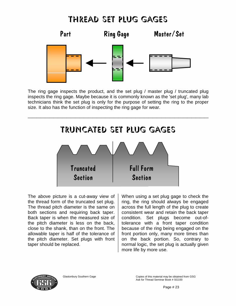
Part Ring Gage Master/Set The ring gage inspects the product, and the set plug / master plug / truncated plug
spects the ring gage. Maybe because it is commonly known as the 'set plug', many lab chnicians think the set plug is only for the purpose of setting the ring to the proper
gages
he above picture e thread form of the thread pitch dia
intesize. It also has the function of inspecting the ring gage for wear.
__________________________________________
Truncated set plug
Full Form Section
TthTboth sections and Back taper is whenthe pitch diameter lose to the shank, c
allowable taper is hthe pitch diameter.taper should be rep
Glas
TruncatedSection
is a cut-away viehe truncated set plmeter is the same on
the front. The
the ed
across the full length of the plug to create
because of the ring being engaged on the
rom GSG Ask for Thread Seminar Book # SG100
w of ug.
When using a set plug gage to checkring, the ring should always be engag
requiring back taper. the measured size of is less on the back, than on
consistent wear and retain the back taper condition. Set plugs become out-of-tolerance with a front taper condition
alf of the tolerance of Set plugs with front laced.
front portion only, many more times than on the back portion. So, contrary to normal logic, the set plug is actually given more life by more use.
Copies of this material may be obtained f
Page # 23
tonbury Southern Gage
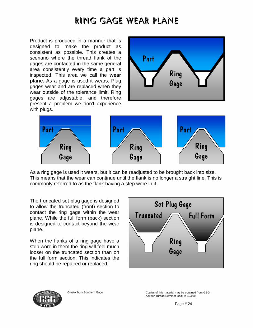
ring gage wear plane Product is prod a manner th
esigned to make the product as onsistent as possible. This creates a cenario where the thread flank of the ages are contacted in the same general rea consistently every time a part is spected. This area we call the wear lane. As a gage is used it wears. Plug ages wear and are replaced when they ear outside of the tolerance limit. Ring
s a ring gage is used it wears, but it can be readjusted to be brought back into size. his means that the inue until the fl er a straight line. This is ommonly referred t having a step w
he truncated set plug gage is designed
eplaced.
Copies of this material may be obtained from GSG
uced in at is dcsgainpgwgages are adjustable, and therefore present a problem we don't experience with plugs.
Part
Ring Gage
AT wear can cont
o as the flank ank is no longore in it. c
Tto allow the truncated (front) section to contact the ring gage within the wear plane, While the full form (back) section is designed to contact beyond the wear plane. When the flanks of a ring gage have a step wore in them the ring will feel much looser on the truncated section than on the full form section. This indicates the ring should be repaired or r
Ask for Thread Seminar Book # SG100
Glastonbury Southern Gage
Page # 24
Part Part Part
Ring Gage
Ring Gage
Ring Gage
Set Plug Gage
Ring Gage
Truncated Full Form
Master Setting plug Design
For Thread Ring Diagnostics & Setting
he first method addressed is used to spect new ring gages, assuming your age not previously set byanu r to your master plug. The
hould be set to the front or truncated ortion, then ue onto the full form ortion to ins r root clearance, and onsistent fe setting plug should be serted a m of two threads into ach end of ring for shake, inspecting for
-inspect rings for wear after use on the
product. The ring should be set to the full form portion, then backed off to the truncated portion for feel. The setting plug shoul inserted a maximum of two threads into each f ring for shake, inspecting for tape The front or truncated portion of the setting plug is designed to contact the flanks of the ring in the wear plane, similar to a product. The full form portion is designed to contact the flanks of the ring beyond the wear plane. When a ring is run across the plug there will be a slight difference in the feel or tightness because the more contact with the flanks on the rm portion of the setting plug, thus more resistance and
r feel.
nificant difference in oted, has wear on the flan d
be repaired or replaced. Setting a ring with le
operly inspect the product threads.
ess of Fit
ess than for a larger size gage.
.
n properly set gages with accurate threads, a very little change to size
(a the ring ga a no ference i wo different setting plugs both within class W tolerance may feel entirely different in the same ring gage. One could be too tight and the other se. It must be realized that a ge set on one setting plug does cessarily mean it will fit another se g. This is due to the allowable tolerance of the set plug. In addition to pitch diameter variations, there may be a slight difference in the flank angle or lead of the ring versus the
rom GSG Ask for Thread Seminar Book # SG100
The Truncated Master Setting Plug Gage is designed for two functions; to set the adjustable thread ring gage, and to inspect the ring gage for wear. Two methods of using the setting plug are suggested to optimize the life of the setting plug. Pitchdiameter taper on the setting plug is specified to always be in the minus direction, i.e. the PD on the front of the plug should always be larger than the PD on the back of the plug.
d be end or.
Tin
re is full fo
g s are facture
the ring m
sa tighte If a sigthe ring
p continpect fo
el. The aximum
pcinetaper. The second method addressed is used to
wear in the flanks will cause possibinterference with the product major and does not pr
re
feel is nk and shoul
Tightn
There are no established torque values fordegree of drag. Some judgment andcommon sense must be used. Theresistance or drag for a small size gagehould be l
djustment of ticeable dif
ge) will effect n drag. T
stoo looring ga not netting plu
A spin fit is obviously much too loose, andtoo tight a fit could damage or causeexcessive wear on the ring or the settingplug. In-between is a fairly smooth drag. This tells you that the size of the ring isssentially the same as the setting pluge
Olapped
Copies of this material may be obtained f
Glastonbury Southern Gage
Page # 25
setting plug. Tincrease in the degree of drag a full engagement versusOne should not expect absol
direction the errors interfere while in the other direction
happens the ring here the flanks do
ass good product and il bad product.
_
INSPECTION / SETT
r nt, wipe clean with isopropyl in
n
3. INSPECT PD
h
ela
tio be
more
r
his can also cause a small ring and the set plug. In one
partial engagements. ute perfection.
they do not. When thisshould be positioned w
These differences are not serious within reason as both the ring and setting plug may be well within their respective tolerances. A ring may feel noticeably different on the set plug when engaged with the marking facing the set plug or facing away from the set plug. This is usually the result of flank angle error in the
_____________________
not interfere (the looser fitting) and set for the proper feel. When this is done the set plug will probably not go in the ring if the ring is turned around, but this gives the closest pitch diameter size for the ring gage and is most likely to p
Using a calibrated tapered pin, set of paralinspect the ID (minor diameter) of ring gage a
fa
____________________
ING PROCEDURE
AD RING
sh and solve
AGD THRE 1. CLEAN Thoroughly clean the threads with a bristle balcohol and clean with kim wipe. Visually foreign material buildup. 2. INSPECT ID
uspect the thread ring for nicks, dings or
lels, bore gage or other accurate method d record the size.
a. Lubricate the setting master plug with ainto the ring gage. b. Turn the ring onto the setting plug 1 1/2 to setting plug go to operation 4. There should bengagement. To test for taper or bellmouth, ptest for shake or looseness with the setting pluthreads. c. Turn ring further onto the truncated secthread engagement. The drag should remainlightly greater at full engagement due to
t in film of light viscosity oil before inserting
2 threads at the front. If ring will not go onto some resistance or drag even at this short ce the ring on its face on a workbench and
g, being very careful not to damage the end
n, remembering the feel at the 1 1/2 to 2 pproximately the same although it may
d. Remove the ring from the setting plug and
as flank contact.
epeat operations 3b & 3c on the opposite
Copies of this material may be obtained from GSG Ask for Thread Seminar Book # SG100
Page # 26
Glastonbury Southern Gage
side of the thread ring gage.
ri
to operation 7.
OTE: If r
urn th . Turn the adjusting screw clo ring to a larger pitch diameter
ing plug.
already been done, turn the locking screw counter-clockwise until it is the adjusting screw counter-clockwise to tighten or clockwise to loosen
screw so that the age remains fixed. There should be noticeable drag between the ring
T PD
e. The fit should be approximately the same on both sides of the ring to insure proper straightness. Remember if a setting plug is manufactured or worn smaller at the front, it will falsely indicate taper or bellmouth in the ng gage. Setting plugs must be reasonably straight. f. Turn the ring gage from the truncated section onto the full form section at the back. The drag should be approximately the same on both sections which insures good flank angle contact. g. If at this point nothing is found which indicates a problem skip 4. SET RING N ing will go onto setting plug skip to operation 4c.
e locking screw counter-clockwise until it is loosened. a. T
b ckwise, this will open thethan the sett c. Turn the ring gage onto the setting plug truncated section so that approximately one thread of setting plug extends beyond the ring. (This will promote uniform wear over the entire thread length of the setting plug.) d. If it has not
Turn loosened. until there is a slight drag between the ring and the setting plug. . Turn the locking screw clockwise until tight. This locks the adjustinge
size of the ring gnd setting plug. a
NOTE: Operations 5c – 5e may need to be repeated more than once to obtain the proper rag or feel. d
f. Turn the ring gage from the truncated section onto the full form section at the back. The drag should be approximately the same on both sections which insures good flank angle contact. . INSPEC5
Repeat section 3a – 3f. If at this point nothing is found which indicates a problem continue to operation 6.
Copies of this material may be obtained from GSG Ask for Thread Seminar Book # SG100
Page # 27
Glastonbury Southern Gage
6. INSPECT ID Using a calibrated tapered pin, set of parallels, or bore gage inspect the ID (minor diameter) of ring gage. NOTE: If an adjustment was necessary to establish the proper feel on the setting plug se the following formula to obtain the as found pitch diameter. (Setting plug pitch
uthorized mpering with the setting of the ring gage.
___________________________________ RING
wipe. Visually inspect the thread ring for nicks, dings or foreign
To test for taper or bellmouth, place the ring on its face on a workbench and
ing further onto the truncated section, remembering the feel at the 1 1/2 to 2 nt. The drag should remain approximately the same although it may be full engagement due to more flank contact.
ing gage.
udiameter) plus (ID size before adjustment )minus (ID size after adjustment.) 7. SEAL Cover the adjusting and locking screws with sealing wax to prevent unata
_______
SOUTHERN STYLE THREAD . CLEAN 1
Thoroughly clean the threads with a bristle brush and solvent, wipe clean with isopropyl lcohol and clean with kima
material buildup. 2. INSPECT ID Using a calibrated tapered pin, set of parallels, or bore gage inspect the ID (minor diameter) of ring gage and record the size. . INSPECT PD 3
a. Lubricate the setting master plug with a thin film of light viscosity oil before inserting into the ring gage. b. Turn the ring onto the setting plug 1 1/2 to 2 threads at the front. If ring will go onto the setting plug go to operation 4. There should be some resistance or drag even at this short ngagement. e
test for shake or looseness with the setting plug, being very careful not to damage the end threads. . Turn rc
thread engagemelightly greater at s
d. Remove the ring from the setting plug and repeat operations 5b & 5c on the opposite ide of the thread rs
Copies of this material may be obtained from GSG Ask for Thread Seminar Book # SG100
Page # 28 Glastonbury Southern
Gage
point nothing is found which indicates a problem skip to operation 5.7.
a. Turn the locking scr
usting screw clockwise 1/8 turn maximum to enlarge ring PD. Repeat, if ntil ring will go onto setting plug.
th of the setting plug.)
ting screw counter-clockwise to loosen or clockwise to tighten.
should be noticeable drag between the ring
swill falsely indicate taper or bellmouth in the ring gage. Setting plugs must be reasonably straight. f. Turn the ring gage from the truncated section onto the full form section at the back. The drag should be approximately the same on both sections which insures good flank angle contact. g. If at this 4. SET RING NOTE: If ring will go onto setting plug skip to operation 4c.
ew counter-clockwise 1/4 turn. b. Turn the adjnecessary, u c. Turn the ring gage onto the setting plug truncated section so that approximately one thread of setting plug extends beyond the ring. (This will promote uniform wear over the entire thread leng d. Turn the adjus e. Turn the locking screw clockwise until tight. This locks the adjusting screw so that the size of the ring gage remains fixed. Thereand setting plug. NOTE: Operations 4c – 4e may need to be repeated more than once to obtain the proper drag or feel. f. Turn the ring gage from the truncated section onto the full form section at the back. The drag should be approximately the same on both sections which insures good flank angle contact. 5. INSPECT PD Repeat section 3a – 3f. If at this point nothing is found which indicates a problem continue to operation 6. 6. INSPECT ID Using a calibrated tapered pin, set of parallels, or bore gage inspect the ID (minor diameter) of ring gage.
Copies of this material may be obtained Ask for Thread Seminar Book # SG100
from GSG
Page # 29
e. The fit should be approximately the same on both sides of the ring to insure proper traightness. Remember if a setting plug is manufactured or worn smaller at the front, it
Glastonbury Southern Gage
NOTE: If an adjustment was necessary to establish the proper feel on the setting plug use the following formula to obtain the as found pitch diameter. (Setting plug pitch diameter) plus (ID size before adjustment) minus (ID size after adjustment.) 7. SEAL
with the setting of the ring gage.
___
OMPUTING GAGE DIMENSIONS
d. Charts for standard sizes and minor diameters. If the size of e is to look in the ANSI B1.1 and
s are known, the following formulae may be
o Full Form Major = Go PD + h
ll For Major = Go FF Maj. or Go FF Maj. + .216506p - (Go PD - NoGo PD + .0017") whichever is smaller
ajor = NoGo PD + H/2
d - H/2 Go PD - .25H
rom GSG Ask for Thread Seminar Book # SG100
Cover the adjusting and locking screws with sealing wax to prevent unauthorized tampering
_______________________________________
C
imensions for gages can be found in the ANSI B1.2 standarDof threads will give pitch diameters, major diameters,
read is not listed in the B1.2 then the next procedurthcompute the pitch diameter limits for the product thread. The formulae required are not included because the charts in the standards should be consulted before computing the itch diameter limits. Once the pitch diameterp
used to compute the other gages dimensions.
h = 0.64952p H = 0.8660254p
THREAD WORK PLUGS
Go Major = Go PD + h NoGo Major = NoGo PD + H/2
setting/master plugs
GGo Truncated Major = Go FF Maj. - .060 + .017 NoGo Fu NoGo Truncated M
THREAD RINGS
Go Minor = Go P
oGo Minor = NoN
Copies of this material may be obtained f
Page # 30
3 2p

INTERNAL PRODUCT THREAD DEPTH
The depth of internal product threads can red quickly and easily with very
ttle extra time by put depth notches or
pecifies a mitwo steps are
bove the face.
hen specifying the length ofsteps we must take into ac
ant to measure, whether full functional e external product
hen measuring the full fdepth, the step is meaenterline of the crest on the first full thread
tep face.
roduct engagement, the step is measured e to
e first full thread ridge should be held to
.5p maximum.
nd on the cceptable
practice, however, for consistency each company should establish which method is to be used. It is possible a company would
h would necessitate additional marking or notes to
Thread Depth Figure
Design of the product is controlled by the
application is the or which method should
be utilized. If product engagement controls the design criteria then we should measure
face of the gage to the step. If product thread depth controls the design, we should measure from the centerline of
igns using product thread depth may be necessary because the bolt length or
t length of the mating product y, as in situations where
replacement parts are made by different manufacturers.
be measulisteps on the Go thread plug gage member. If the criteria for the product specifies
need to use both methods, whic
minimum depth only, one step is all that is needed. If the criteria for the product
identify which method is used on each individual gage as well as on the blueprints
s nimum and a maximum, then needed.
for the products and the gages.
The Go member is inserted into the product until fully engaged without the application of significant force, which could tend to deform the product material. The position of the steps in relation to the face of the product is noted to determine conformance. A minimum step should be below the face, a maximum step should be
a W the step or
count what we
wthread depth or effectivengagement. W unctional thread
sured from the application. Thecontrolling factor f
cridge of the Go plug gage to the sWhen measuring the effective external from thepfrom the front face of the Go plug gagthe step face, and the distance from the the first full thread to the step. Desfront face to the centerline of the crest onth
The length of the thread depth step is marked on the Go plug gage aandle. Both methods are ah
engagemencould var
Copies of this material may be obtained from GSG Ask for Thread Seminar Book # SG100
Glastonbury Southern Gage
Page # 31
60° 60°
30° 30°
55°
27½° 27½°
29°
14½° 14½°
common THREAD forms
52°
45°7°
British / Whitworth
_
R
to eal at the threads. For threads to seal
apered threads use a completely different
most common is the NPT, hich is used in many various applications
and which is the basis of which many of the other styles are modifications.
American Inch & Metric
Acme / Stub Acme
_____________________
PIPE TH Pipe threads are threads that seal. Pipe threads seal by various methods, but the ones we are going to concern ourselves with here are th
there are two ways to accomplish a seal, assemble two tapered threads or assemble a straight thread with a tapered thread.
Buttress
____________________
EADS
system to determine size than the Go / NoGo system used in straight threads, (the standard inch and metric series are straight threads). There are many different types and styles of pipe threads, far too numerous to try to address here individually. The
ose that are designed s
T
w
Copies of this material may be obtained from GSG Ask for Thread Seminar Book # SG100
Page # 32
Glastonbury Southern Gage
Taper to Straight Seals
Taper to Taper - Seals
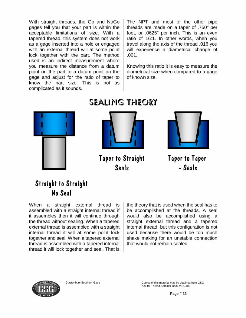
With straight threagages tell you thatcceptable limitations of size. With a pered thread, this system does not work
sed is an indirect measurement where ou measure the distance from a datum oint on the part to a datum point on the age and a t for the ratio of taper to now the part size. This is not as omplicated as it sounds.
the other pipe of .750" per
foot, or .0625" per inch. This is an even ra o of 16:1. In other words, when you tr el along the axis th .016 you w experience a diametrical change of .001. Knowing this ratio it is easy to measure the di metrical size en compared to a gage of nown size.
Sealing theory
Ws
ds, the Go and NoGo your part is within the
The NPT and most ofthreads are made on a taper
ataawlouypg djuskc
tiav of the read ill
a wh k
ait thexintothth
s a gage inserted into a hole or engaged ith an external thread will at some point ck together with the part. The method
Straight to StraightNo Seal
hen a straight external sembled with a straight intern
t is has to hed at the threads. A seal
thread is al thread if
the theory thabe accomplis
used when the seal
assembles then it will continue through e thread without sealing. When a tapered ternal thread is assembled with a straight ternal thread it will at some point lock gether and seal. When a tapered external read is assembled with a tapered internal read it will lock together and seal. That is
would also be accomplished using a straight external thread and a tapered internal thread, but this configuration is not used because there would be too much shake making for an unstable connection that would not remain sealed.
Copies of this material may be obtained from GSG Ask for Thread Seminar Book # SG100
Page # 33
Glastonbury Southern Gage
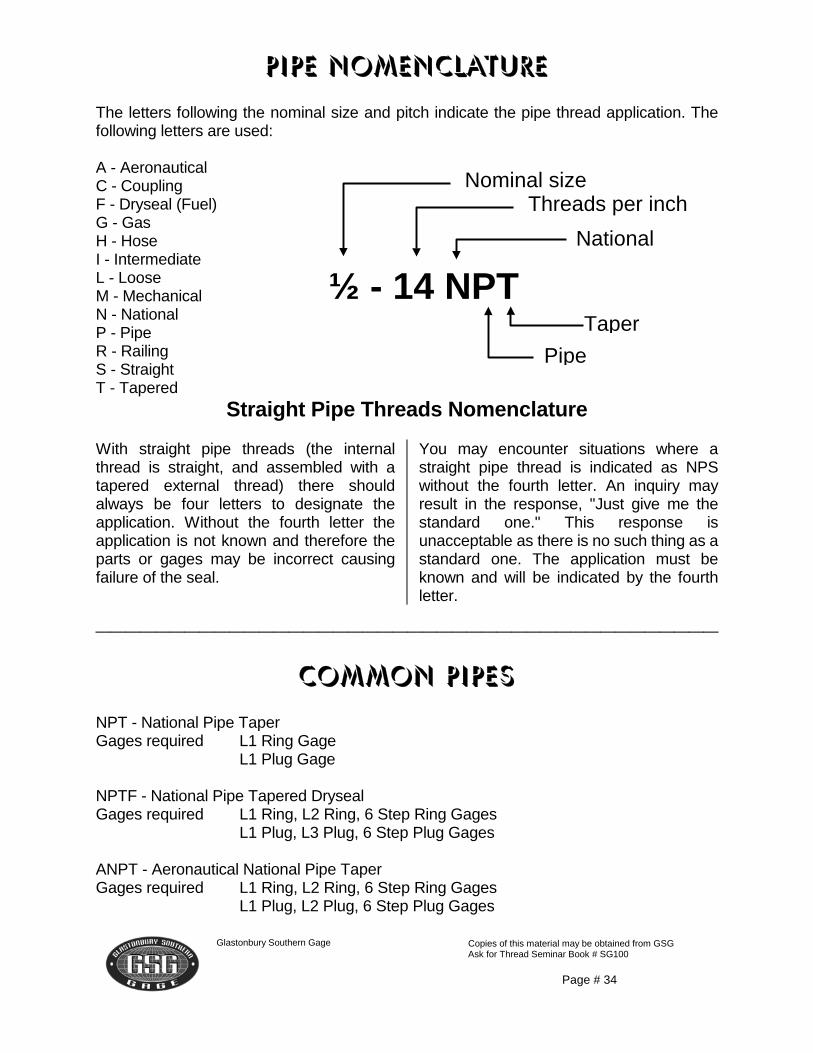
½ - 14 NPT
Nominal size Threads per inch
National
Taper Pipe
Pipe nomen
c
- National P - Pipe R - Railing
- Straight - Tapered
Straight Pipe Threads Nomenclature
ith straight pipe threads (the internal read is straight, and assembled with a pered external thread) there should lways be four letters to designate the pplication. Without the fourth pplication is not known and therarts or gages may be incorrect causiilure of the seal.
You may encounter situations where a straight pipe thread is indicated as NPS without the fourth letter. An inquiry may result in the response, "Just give me the
one." is able as ther as a
ndard one. The a ust be known and will be indicated by the fourth letter.
____________________________
Plug Gages
NPT - Aeronautical National Pipe Taper ages required L1 Ring, L2 Ring, 6 Step Ring Gages
L1 Plug, L2 Plug, 6 Step Plug Gages
clature
h indicate the pipe thread application. The
N
ST
Wthtaa
letter the efore t
standard accept
This response e i ings no such th
pplication m
ahe ng
unsta
apfa
______________
Common pipes NPT - National Pipe Taper Gages required L1 Ring Gage L1 Plug Gage NPTF - National Pipe Tapered Dryseal Gages required L1 Ring, L2 Ring, 6 Step Ring Gages
L1 Plug, L3 Plug, 6 Step AG
Copies of this material may be obtained fAsk for Thread Seminar Book # SG100
rom GSG
Page # 34
The letters following the nominal size and pitfollowing letters are used: A - Aeronautical C - Coupling F - Dryseal (Fuel) G - Gas H - Hose I - Intermediate L - Loose M - Mechanical
Glastonbury Southern Gage
1 R
Angle that createsDiametLength to
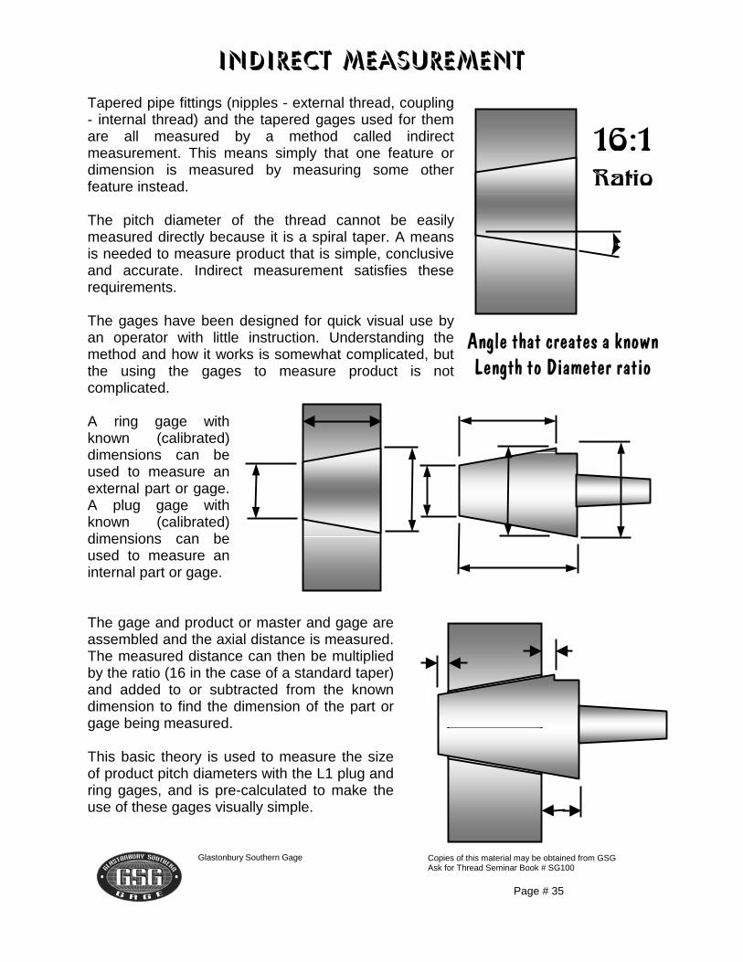
Indirect measurement
tapered gages used for them re all measured by a method called indirect
his means simply that one featur measured by measuring some
diameter of the thread cannot be easily tly because it is a spi
to measure product thIndirect measur
.
have been designed for quick visual use by with little instruction. Understanding the how it works is somewhat complicated, but
the using the gomplicated.
be
The gage and product or m
ssembled and the axial distance is measured. n then be multiplied
ndard taper) nown
imension to find the dimension of the part or
y isf product pitch diameter
e the es
Tapered pipe fittings (nipples - external thread, coupling - internal thread) and the ameasurement. T e or
other dimension isfeature instead. The pitchmeasured direc ral taper. A means
at is simple, conclusive ement satisfies these
is needed and accurate. requirements The gages an operatormethod and
ages to measure product is not c A ring gage with known (calibrated) dimensions can be used to measure an external part or gage. A plug gage with known (calibrated)
imensions can dused to measure an internal part or gage.
aster and gage are aThe measured distance ca
n thby the ratio (16 i e case of a staand added to or subtracted from the kdgage being measured.
his basic theorT used to measure the size s with the L1 plug and o
ring gages, and is pre-calculated to makuse of these gag visually simple.
Copies of this material may be obtained fromAsk for Thread Seminar Book # SG100
Page # 35
Glastonbury Southern Gage
6:1
atioa known er ratio
GSG
+/- 1 Turn +/- 1 Turn
L1 Gage
Internal Part Internal Part
L1 Gage +/- 1 Turn External
Part
L1 Gage
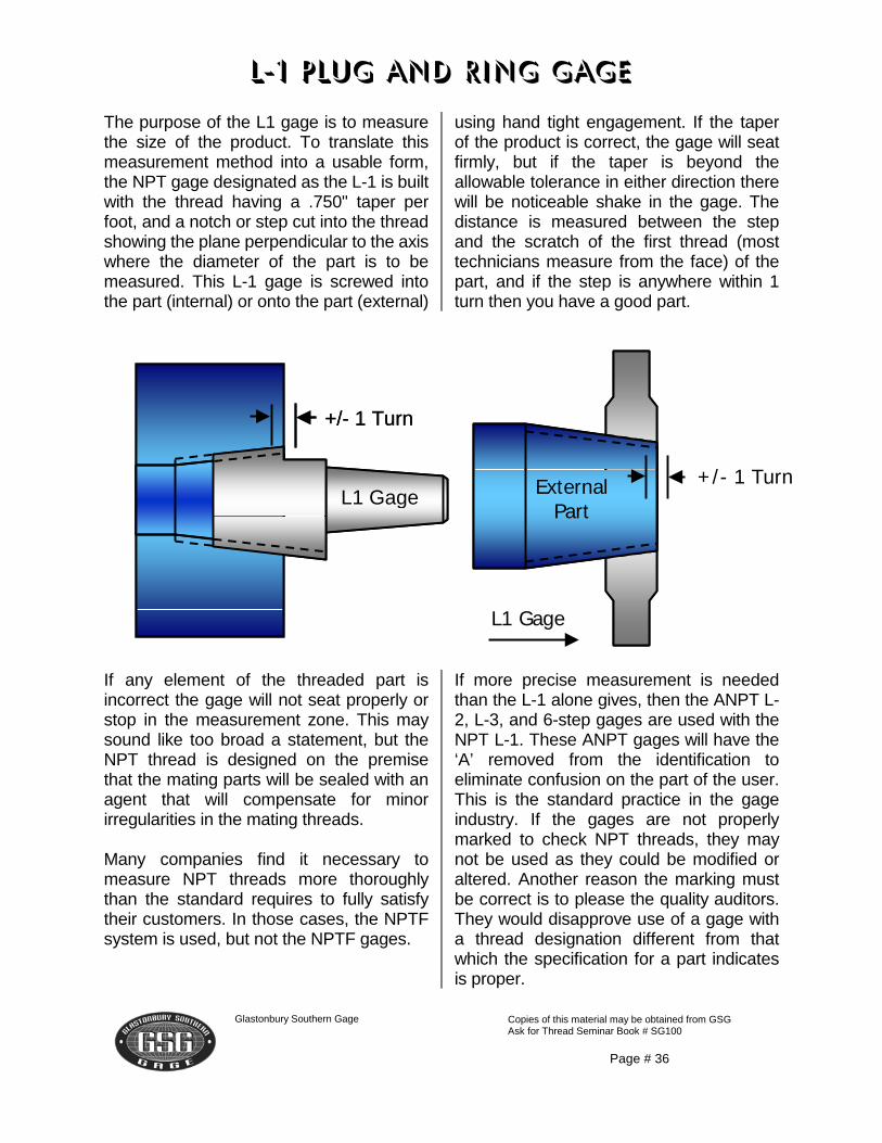
L-1 plug and Ring Gage
or step cut into the thread howing the plane perpendicular to the axis
tight engagement. If the taper t is correct, the gag
is berance in either direcable shake in the
distance is measured between the step and the scratch of the first thread (most
easure from the face) of the the step is anywhere within 1 have a good part.
e threaded part is correct the gage will not seat properly or top in the measurement zone. This may
it necessary to easure NPT threads more thoroughly
If more precise measurement is needed than the L-1 alone gives, then the ANPT L-2, L-3, and 6-step gages are used with the
T L-1. These ANPT gages will have the removed from the identification to inate confusion on the part of the user.
s is the standard practice in the gage stry. If the gages are not properly
rked to check NPT threads, they may not be used as they could be modified or altered. Another reason the marking must
correct is to please the quality auditors. y would disapprove use of a gage with
ead designation different from that which the specification for a part indicates is proper.
The purpose of the L1 gage is to measure the size of the product. To translate this measurement method into a usable form, the NPT gage designated as the L-1 is built with the thread having a .750" taper per foot, and a notch
using hand of the producfirmly, but if the taperallowable tolewill be notice
swhere the diameter of the part is to be measured. This L-1 gage is screwed into the part (internal) or onto the part (external)
technicians mpart, and if turn then you
e will seat yond the tion there
gage. The
If any element of thinssound like too broad a statement, but the NPT thread is designed on the premise that the mating parts will be sealed with an agent that will compensate for minor irregularities in the mating threads. Many companies find
NP‘A’ elimThiinduma
mthan the standard requires to fully satisfy their customers. In those cases, the NPTF system is used, but not the NPTF gages.
be Thea thr
Copies of this material may be obtained from GSG Ask for Thread Seminar Book # SG100
Page # 36
Glastonbury Southern Gage
Internal Part
L3 Gage
+/- ½ Turn
Internal Part ernal Part
L1 Gage
+/
Internal Part
L3 Gage
+/- ½ Turn
Int
L1 Gage
+/- ½ Turn
L
External Part
+/- ½ Turn
L
External Part
+/- ½ Turn
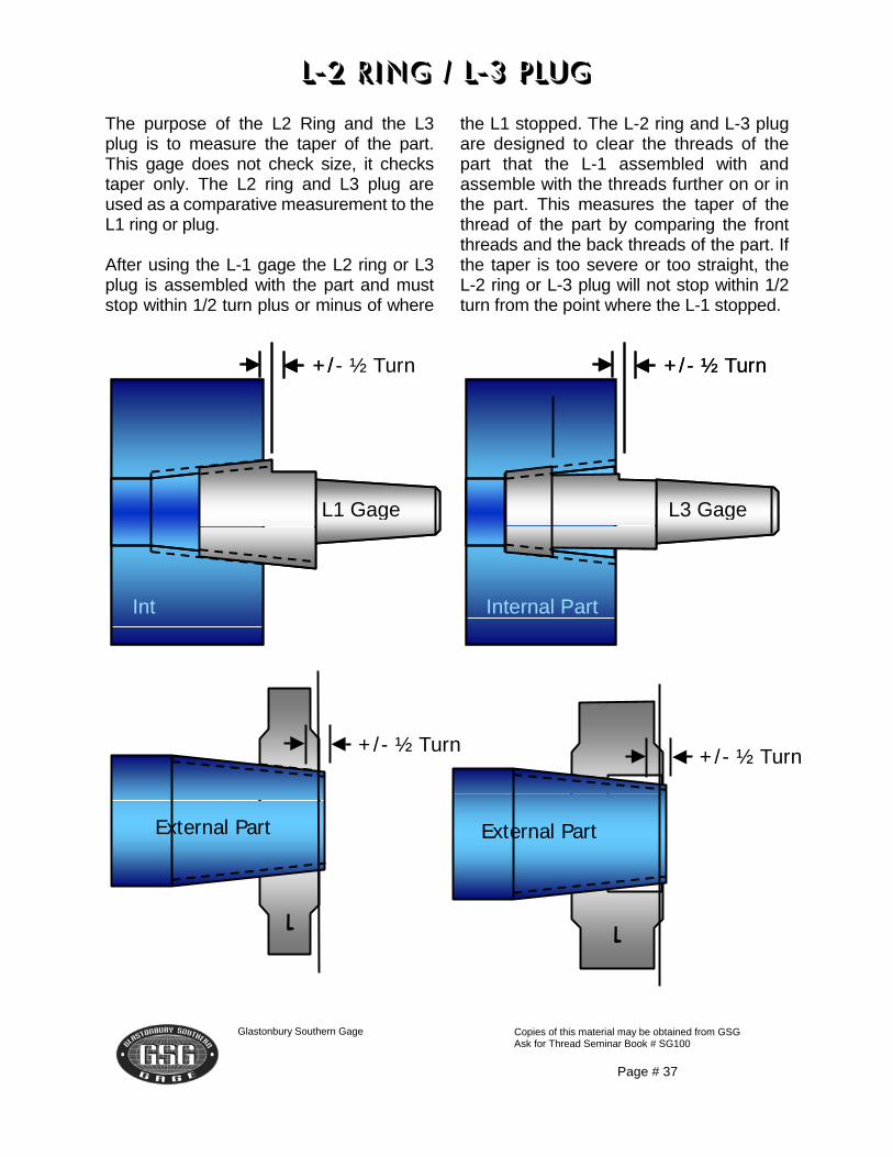
L-2 ring / l-3 plug
the L1 stopped. The L-2 ring and L-3 plug are designed to clear the threads of the part that the L-1 assembled with and assemble with the threads further on or in the part. This measures the taper of the thread of the part by comparing the front threads and the back threads of the part. If the taper is too severe or too straight, the L-2 ring or L-3 plug will not stop within 1/2 turn from the point where the L-1 stopped.
Copies of this material may be obtained from GSG Ask for Thread Seminar Book # SG100
Page # 37
The purpose of the L2 Ring and the L3 plug is to measure the taper of the part. This gage does not check size, it checks taper only. The L2 ring and L3 plug are used as a comparative measurement to the L1 ring or plug. After using the L-1 gage the L2 ring or L3 plug is assembled with the part and must stop within 1/2 turn plus or minus of where
Glastonbury Southern Gage
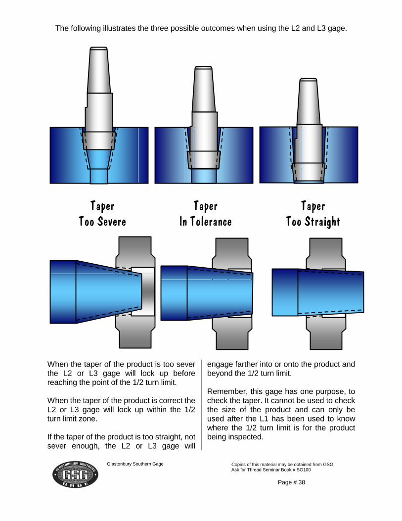
Taper Too Severe
Taper In Tolerance
Taper Too Straight
The following illustrates the L2 and L3 gage.
hen the taper of the product is too sever e L2 ill lock up before
ng the point of the 1/2 turn limit.
hen the taper of the product is correct the 2 or L3 gage will lock up within the 1/2 rn limit zone.
the taper of the product is too straight, not ever enough, the L2 or L3 gage will
engage farther into or onto the product and be limit. Remember, this gage has one purpose, to check the taper. It cannot be used to check the size of the product and can only be used after the L1 has been used to know where the 1/2 turn it is for the product being inspected.
the three possible outcomes when using
Copies of this material may be obtained from GSG Ask for Thread Seminar Book # SG100
Page # 38
Wth or L3 gage w yond the 1/2 turnreachi WLtu limIfs
Glastonbury Southern Gage
dryseal The NPTF design is different from the NPT
that it is designed to create a seal ithout the use of any type of sealants, i.e. ryseal. The standard for NPTF threads NSI B1.20.3) allows Class 1 and Class 2
pplications.
he Class 1 applications do not require spection of the crest and root diameters. onsequently, Class 1 threads are tended for applications where close ontrol of tooling is required for onformance of truncation or where sealing allowed to be accomplished by means of sealant applied to the threads. Class 2 pplications require the inspection of the rest and ro ation, to create morssurance o sure-tight seal wherealants
he ANPT design is not a dryseal design, ut because of the use of these threads in eronautical applications, which is safety ritical, the NPTF inspection method is
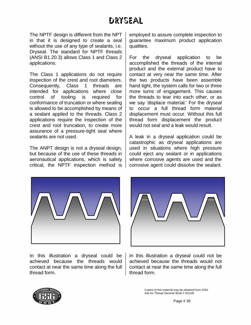
employed to assure complete inspection to guarantee maximum product application qualities. For the dryseal application to be accomplished the threads of the internal product and the external product have to contact at very near the same time. After the two products have been assemble hand tight, the system calls for two or three more turns of engagement. This causes the threads to tear into each other, or as we say 'displace material.' For the dryseal to occur a full thread form material displacement must occur. Without this full thread form displacement the product
ld not seal and a leak w ult.
n a dryseal a be hic as dryse e
used in situations where high pressure could eject any sealant or in applications where corrosive agents are used and the corrosive agent could dissolve the sealant.
d ontact at near the same time along the full
inwD(Aa TinCinccisaa
e e
wou
ould resc ot truncf a presa
A leak icatastrop
pplication could al applications ar
s are not used. Tbac In this illustration a dryseal could be achieved because the threads woulcthread form.
In this illustration a dryseal could not be achieved because the threads would not contact at near the same time along the full thread form.
Copies of this material may be obtained from GSG Ask for Thread Seminar Book # SG100
Page # 39
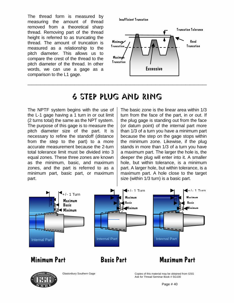
Truncation Tolerance
Good Truncation
Excessive
Insufficient Truncation
imMin um Truncation
Maximum Truncation
+/- 1 Turn
Internal Part
Maximum Basic Minimum
23 2
323
23 2
323
Internal Part
Maximum
Basic
Minimum
+/- 1 Turn
23 2
3 23
Internal Part
Maximum
Basic
Minimum
+/- 1 Turn
MMiinniimmuumm PPaarrtt BBaassiicc PPaarrtt MMaaxxiimmuumm PPaarrtt
The thread form is measured bmeasuring the amount of threa
moved from a theoretical sharp
rest of the thread to the itch diameter of the thread. In other
the part. It is
s the minimum, basic, and maximum ones, and the part is referred to as a inimum part, basic part, or maximum
art.
ace
hole, but within tolerance, is a minimum part. A larger hole, but within tolerance, is a maximum part. A hole close to the target size (within 1/3 turn) is a basic part.
rom GSG Ask for Thread Seminar Book # SG100
y d
rethread. Removing part of the thread height is referred to as truncating the thread. The amount of truncation is measured as a relationship to the pitch diameter. This allows us to compare the cpwords, we can use a gage as a comparison to the L1 gage.
______________________
6 step plug The NPTF system begins with the use of the L-1 gage having a 1 turn in or out limit (2 turns total) the same as the NPT system. The purpose of this gage is to measure the itch diameter size of
____________________
and ring
The basic zone is the linear area within 1/3 turn from the face of the part, in or out. If
e plug gage is standing out from the f
pnecessary to refine the standoff (distance from the step to the part) to a more accurate measurement because the 2-turn total tolerance limit must be divided into 3 qual zones. These three zones are known e
azmp
th(or datum point) of the internal part more than 1/3 of a turn you have a minimum part because the step on the gage stops within the minimum zone. Likewise, if the plug stands in more than 1/3 of a turn you have a maximum part. The larger the hole is, the deeper the plug will enter into it. A smaller
Copies of this material may be obtained f
Glastonbury Southern Gage
Page # 40
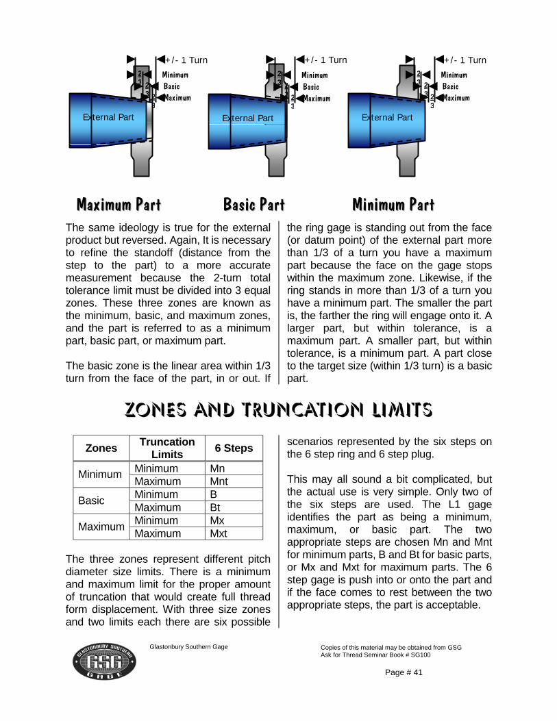
External Part
Maximum
Basic
Minimum
+/- 1 Turn 23 2
3 23
External Part
Maximum
Basic
Minimum
+/- 1 Turn 23 2
External Part
Ma
Basic
+/- 1 Turn
3 23
ximum
Minimum 23 2
3 23
MMaaxxiimmuumm PPaarrtt BBaassiicc PPaarr MMiinniimmuumm PPaarrtt tt
The same ideology is
oduct but reversed. ng out from the face external part more
Zones Truncation 6 Steps
true for the external Again, It is necessary
the ring gage is standi(or datum point) of thepr
to refine the standoff (distance from the step to the part) to a more accurate measurement because the 2-turn total tolerance limit must be divided into 3 equal zones. These three zones are known as the minimum, basic, and maximum zones, and the part is referred to as a minimum part, basic part, or maximum part. The basic zone is the linear area within 1/3 turn from the face of the part, in or out. If
Zones and trun
than 1/3 of a turn you have a maximum part because the face on the gage stops within the maximum zone. Likewise, if the ring stands in more than 1/3 of a turn you have a minimum part. The smaller the part is, the farther the ring will engage onto it. A larger part, but within tolerance, is a maximum part. A smaller part, but within tolerance, is a minimum part. A part close to the target size (within 1/3 turn) is a basic part.
cation limits
Limits Min Mn imum Minimum a Mnt M ximum Min B imum Basic aM ximum Bt Minimum Mx Maximum Maximum Mxt
The three zones represent different pitch
limits. There is a mnd maximum limit for the proper amount f truncation that would create full thread
With three size there are six p
scenarios represented by the six steps on the and 6 step plug.
h ay all sound a bit compli , but l use is very simpl of
six steps are used. The L1 gage identifies the part as being a minimum, maximum, or basic part. The two appropriate steps are chosen Mn and Mnt for minimum parts, B and Bt for basic parts, or Mx and Mxt fo parts. The 6 step gage is push into or onto the part and if the face comes to rest between the two
opriate steps, the par e.
6 step ring
T is m
diameter size inimum aoform displacement. nd two limits each
zones ossible
appra
catedthe actua e. Only two the
r maximum
t is acceptabl
Copies of this material may be obtained from GSG Ask for Thread Seminar Book # SG100
Page # 41
Glastonbury Southern Gage
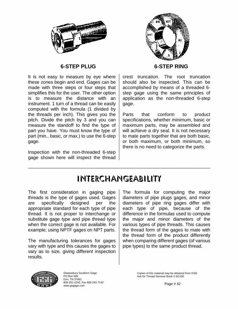
6-STEP PLUG 6-STEP RING
is not easy to measure by eye where e
ps or four implifies this for the user. The other option
spection with the non-threaded 6-step
crest truncation. The root truncation d also be i is can be
ccomplished readed 6-step gage using the same principles of
_ _________________
The on g pe threads is the es used. Gages ar c ned per the appropriate st each of pipe thr is n n hange or substitute gag pipe ead type wh not a e. For
ample; usin es o T parts.
and minor
Copies of this material may be obtained from GSG
Itth se zones begin and end. Gag
ade with three stees can be steps that
shoulam
sis to measure the distance with an instrument. 1 turn of a thread can be easily computed with the formula (1 divided by the threads per inch). This gives you the pitch. Divide the pitch by 3 and you can measure the standoff to find the type of part you have. You must know the type of part (min., basic, or max.) to use the 6-step gage. Ingage shown here will inspect the thread
application as the non-threaded 6-step gage. Parts that conform to product specifications, whether minimum, basic or maximum parts, may be assembled and will achieve a dry seal. It is not necessary to mate parts together that are both basic, or both maximum, or both minimum, so there is no need to categorize the parts.
____________________ ___
nspected. Th by means of a th
_
Interchangeability
first c sideration inag
aging pi type of g
e specifi ally desigandard for type
ead. It ot proper to i terce type and thr
vailablen the correct gage isex
g NPTF gag n NP
The manufacturing tolerances for gages vary with type and this causes the gages to vary as to size, giving different inspection results.
The formula for computing the major iameters of pipe plugs gages,
ddiameters of pipe ring gages differ with each type of pipe, because of the difference in the formulas used to compute the major and minor diameters of the various types of pipe threads. This causes the thread form of the gages to mate with the thread form of the product differently when comparing different gages (of various pipe types) to the same product thread.
Ask for Thread Seminar Book # SG100
Glastonbury Southern Gage
ax 800-242-7142 Page # 42
PO Box 509 1 Erin, TN 3706
800-251-4243, Fwww.gsgage.com
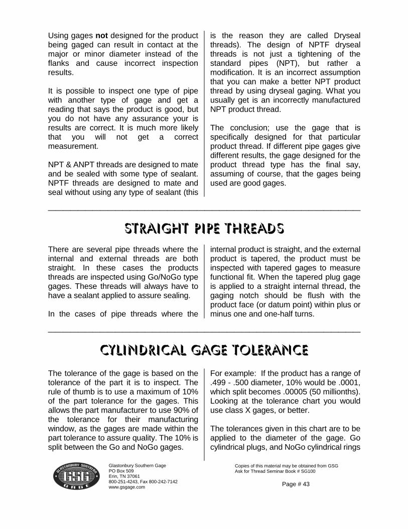
Using gages not designed for the product being gaged can result in contact at the major or minor diameter instead of the flanks and cause incorrect inspection results. It is possible to inspect one type of pipe with another type of gage and get a
is the reason they are called Dryseal threads). The design of NPTF dryseal threads is not just a tightening of the standard pipes (NPT), but rather a modification. It is an incorrect assumption that you can make a better NPT product thread by using dryseal gaging. What you usually get is an incorrectly manufactured
re good gages.
_P
here are several pipe threads where the
have a sealant applied to assur
pipe
l
inspected with tapered gages to measure
d be flush with the m point) within plus or alf turns.
f the part tolerance for the gages. This
ance to assure quality. The 10% is plit between the Go and NoGo gages.
he tolerances given in this chart are to be pplied to the diameter of the gage. Go
cylindrical plugs, and NoGo cylindrical rings
reading that says the product is good, but ou do not have any assurance your is
NPT product thread. y
results are correct. It is much more likely that you will not get a correct measurement. NPT & ANPT threads are designed to mate and be sealed with some type of sealant. NPTF threads are designed to mate and seal without using any type of sealant (this
_____________________
STRAIGHT PI
The conclusion; use the gage that is specifically designed for that particular product thread. If different pipe gages give different results, the gage designed for the product thread type has the final say, assuming of course, that the gages being sed a
internal and external threads are both straight. In these cases the products
u
____________________ E THREADS
internal product is straight, and the externaproduct is tapered, the product must be
T
threads are inspected using Go/NoGo type gages. These threads will always have to
functional fit. When the tapered plug gage is applied to a straight internal thread, the
e sealing.
threads where the
gaging notch shoulproduct face (or datuminus one and one-hIn the cases of
______________________
CYLINDRICAL GA The tolerance of the gage is based on the tolerance of the part it is to inspect. The rule of thumb is to use a maximum of 10%
____________________ GE TOLERANCE
For example: If the product has a range of .499 - .500 diameter, 10% would be .0001, which split becomes .00005 (50 millionths). Looking at the tolerance chart you would use class X gages, or better.
oallows the part manufacturer to use 90% of the tolerance for their manufacturing window, as the gages are made within the part tolers
Ta
Copies of this material may be obtained from GSG Ask for Thread Seminar Book # SG100
Glastonbury Southern Gage PO Box 509 Erin, TN 37061 800-251-4243, Fax 800-242-7142 www.gsgage.com Page # 43
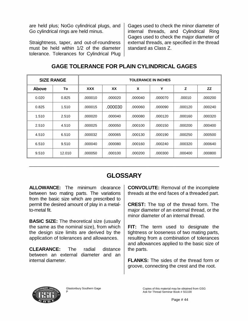
are held plus; NoGo cylindrical plugs, and Go cylindrical rings are held minus. Straightness, taper, and out-of-roundness
ust bem held within 1/2 of the diameter
A GES
tolerance. Tolerances for Cylindrical Plug
GAGE TOLERANCE FOR PL
SIZE RANGE
Gages used to check the minor diameter of internal threads, and Cylindrical Ring Gages used to check the major diameter of external threads, are specified in the thread standard as Class Z.
IN CYLINDRICAL GA
TOLERANCE IN INCHES
Above To XXX XX X Y Z ZZ
0.020 0.825 .000010 .000020 .000040 .000070 .00010 .000200
0.825 1.510 .000015 .000030 .000060 .000090 .000120 .000240
1.510 2.510 .000020 .000040 .000080 .000120 .000160 .000320
2.510 4.510 .000025 .000050 .000100 .000150 .000200 .000400
4.510 6.510 .000250 .000500 .000032 .000065 .000130 .000190
6.510 9.510 .000320 .000640 .000040 .000080 .000160 .000240
9.510 12.010 .000050 .000100 .000200 .000300 .000400 .000800
______________________
GLOS
____________________ ARY
ALLOWANCE: The minimum clearance CONVOLUTE: Removal of the incomplete
S
to-metal fit.
ASIC SIZE: The theoretical size (usually
ead, or the hread.
GSG
Ask for Thread Semin 0
between two mating parts. The variations from the basic size which are prescribed to ermit the desired amount of play in a metal-
threads at the end faces of a threaded part. CREST: The top of the thread form. The p
Bthe same as the nominal size), from which the design size limits are derived by the application of tolerances and allowances. CLEARANCE: The radial distance between an external diameter and an internal diameter.
major diameter of an external thrminor diameter of an internal t
FIT: The term used to designate the tightness or looseness of two mating parts, resulting from a combination of tolerances and allowances applied to the basic size of the parts. FLANKS: The sides of the thread form or groove, connecting the crest and the root.
Copies of this material may be obtained fromar Book # SG10
Glastonbury Southern Gage
Page # 44
P
FLANK ANGLE: The angle between the flank and a line perpendicular to the axis of the thread. Also referred to as half angle or
noted.
UNCTIONAL DIAMETER: The actual (mea diameter of a thread adju mulative effects of lead er angl rror, w is alw s added to exter eads subtrfro rnal th . INCLUDED ANGLE: Total of the twan f a thre rm. LE he distance advanced by a wh tated 360 degrees on its mthread. LIMITS: The la trin the size of a di on.
a thread form. The root diameteternal thread and the crest diamete
r of an external thread.
nter
on adjacent threads. The inverse of the threads per inch.
eoretical diametrical plane, which passes through a
here the width of the ve are equal.
RE Remov mater rom porof ace ete void contact w ati hen it is enga R NC : ste gener hel ose tol ance l s w es or p com w king . A ted plug is a reference gage that is used to in s w set ble rin s.
r diameter of an external thread.
and mum di
lead angle. Some exceptions to this definition will be encountered, such as tapered thread flank angles measured perpendicular to the taper, and should be
NOMINAL SIZE: The size used for purposes of identification. Usually the same as the basic size. PITCH: The distance between corresponding points
Fsured) pitch
sted by the curor and e e hich ay
nal thrreads
and acted m inte
o flank gles o ad fo
AD: T thread en ro ating
rgest and smalmensi
lest ex emes
AJOR DIAMETER: The largest diameter
ROOT: The bottom of the thread form. The major diameter of an internal thread and M
of r of an r of an
the mino in
external thread. MINOR DIAMETER: The smallest diameter of a thread form. The bore or crest diameter of an internal thread and the root diamete NOMENCLATURE: In relation to a thread, the complete identification, including the nominal size, threads per inch or pitch, thread series, class of fit, and possibly a designation for i nal or external.
PITCH DIAMETER: The th
thread at the point wthread tooth and groo
LIEF: a surf
al of or diam
ial fr to a
tions
ith the m ng part w ged.
EFERE E GAGE A ma r gageally
hich is prd to clerved f
ereriodic
imitparison
ith wor gages trunca setting
spect a ell as adjusta threadg gage
THREAD ANGLE: The included angle of the thread form, which has the two thread flanks as sides. TOLERANCE: The amount of variation permitted from the designated dimension, or the difference between the minimummaxi mensions. TRUNCATE: To remove the crest of a thread, thus reducing its height, usually done to guarantee non-interference.
Copies of this material may be obtained Ask for Thread Seminar Book # SG100
from GSG
Page # 45
Glastonbury Southern Gage
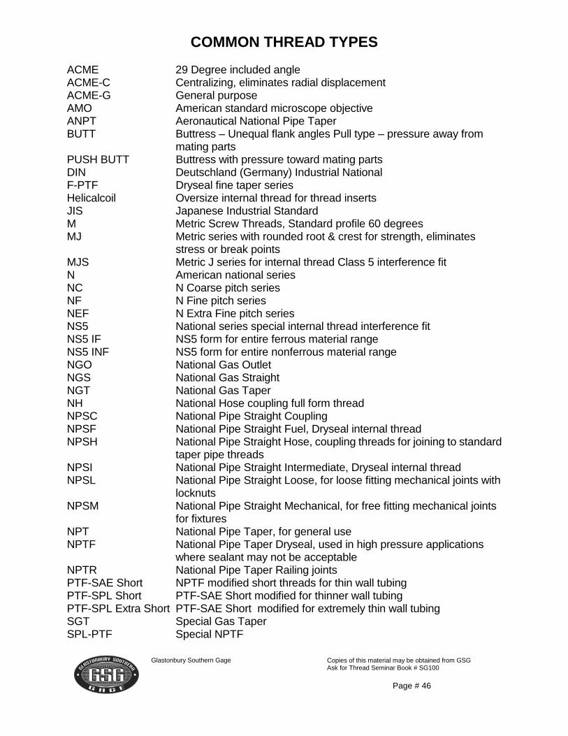
COMMON TH ACME 29 Degree included anACME-C Centralizing, eliminatesACME-G General purpose AMO American standard micANPT Aeronautical National PBUTT Buttress – Unequal fla
R
g t
r
nkmating parts
o)sd
SMetric series with round
rnerican national serie
sNational series special i
rronf rial range
nal Gas Outlet
g f C
National Pipe Straight F
In L
M
ry
t b Taper Rai
TF-SAE Short NPTF modified short thr ads for thin wall tubing TF-SPL Short PTF-SAE Short modified for thinner wall tubing TF-SPL Extra Short PTF-SAE Short modified for extremely thin wall tubing GT Special Gas Taper PL-PTF Special NPTF
EAD TYPES
le al displacemenradi
oscope objective ipe Taper
angles Pull type – pressure away from
PUSH BUTT Buttress with pressure tDIN Deutschland (GermanyF-PTF Dryseal fine taper serieHelicalcoil Oversize internal threaJIS Japanese Industrial StaM Metric Screw Threads,
J
ward mating parts Industrial National or thread inserts f
ndard tandard profile 60 degrees
ed root & crest for strength, eliminates Mstress or break points
MJS Metric J series for inte Am
al thread Class 5 interference fit s
nternal thread interference fit us material range rrous mate
NNC N Coarse pitch series NF N Fine pitch series NEF N Extra Fine pitch serie
S5 NNS5 IF NS5 form for entire feNS5 INF NS5 form for entire no
GO Natioe
NNGS National Gas Straight NGT National Gas Taper NH National Hose couplinNPSC National Pipe Straight
PSF
ull form thread oupling uel, Dryseal internal thread
se, coupling threads for joining to standard NNPSH National Pipe Straight Ho
taper pipe threads NPSI National Pipe Straight NPSL National Pipe Straight
locknuts
termediate, Dryseal internal thread oose, for loose fitting mechanical joints with
echanical, for free fitting mechanical joints NPSM National Pipe Straightfor fixtures
NPT National Pipe Taper, foNPTF National Pipe Taper Dr
where sealant may noPTR National Pipe
general use seal, used in high pressure applications e acceptable ng joints N li
ePPPSS
Copies of this material may be obtained from GSG Ask for Thread Seminar Book # SG100
Page # 46
Glastonbury Southern Gage
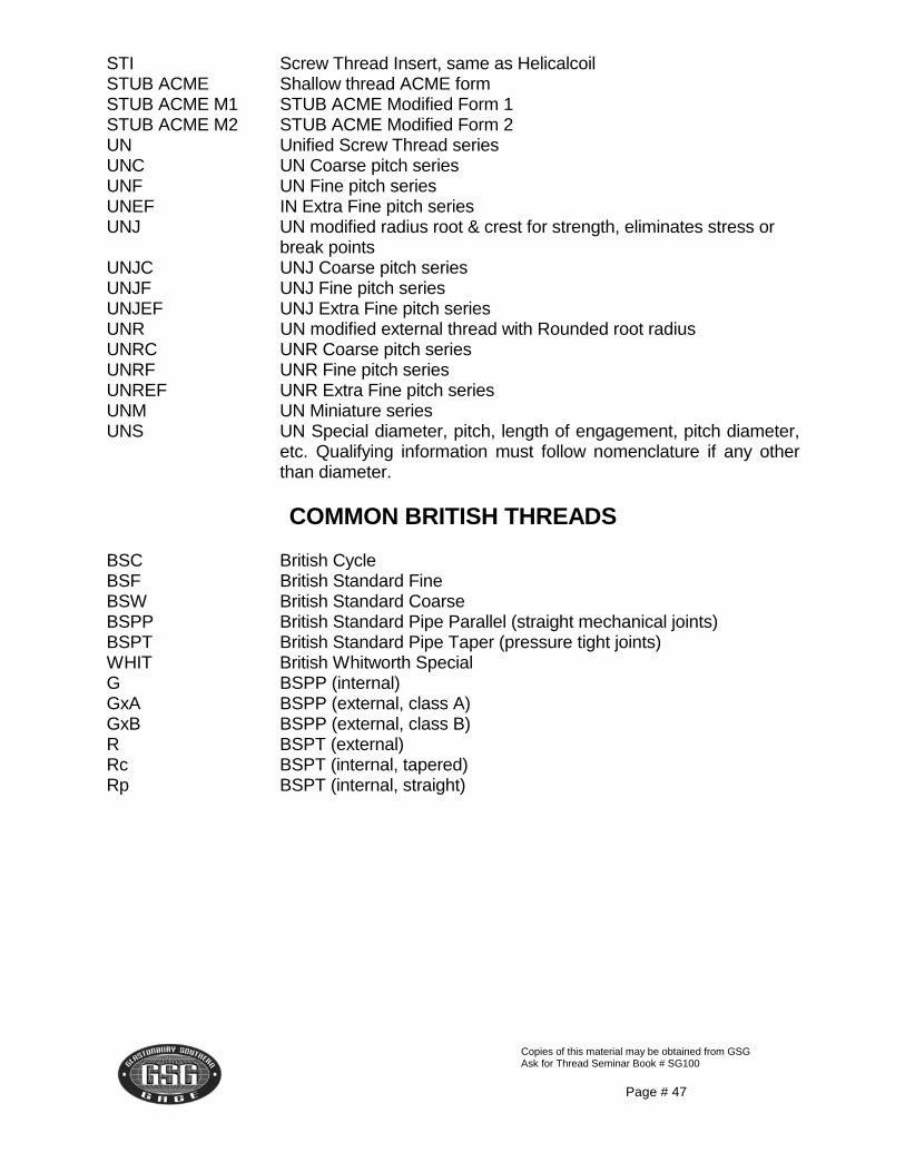
STI ScrTUB ACME Sh
CME M1 1 ME M2
C F
F
ameter, ollow nomenclature if any other
e
Parallel (straight mechanical joints) T ht joints)
GxB ss B)
Rp ernal, straight)
ew Thread Insert, same as Helicalcoil allow thread ACME form S
STUB A STUB ACME Modified FormSTUB AC STUB ACME Modified Form 2 UN Unified Screw Thread series UNC UN Coarse pitch series UNF UN Fine pitch series UNEF IN Extra Fine pitch series UNJ UN modified radius root & crest for strength, eliminates stress or
on must fetc. Qualifying informatithan diameter.
COMMON BRITISH THREADS
BSC British Cycle BSF British Standard FineBSW British Standard CoarsBSPP British Standard PipeBSP British Standard Pipe Taper (pressure tigWHIT British Whitworth Special G BSPP (internal) GxA BSPP (external, class A)
BSPP (external, claR BSPT (external) Rc BSPT (internal, tapered)
BSPT (int
Copies of this material may be obtained from GSG Ask for Thread Seminar Book # SG100
Page # 47
break points UNJC UNJ Coarse pitch series UNJF UNJ Fine pitch series UNJEF UNJ Extra Fine pitch series UNR UN modified external thread with Rounded root radius UNR UNR Coarse pitch series UNR UNR Fine pitch series UNRE UNR Extra Fine pitch series UNM UN Miniature series UNS UN Special diameter, pitch, length of engagement, pitch di
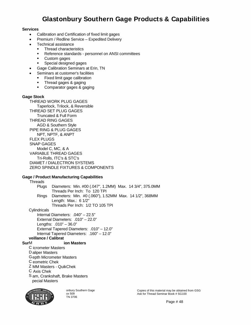
Glastonbury Southern Gage Products & Capabilities Ser
rtificremium / Redline Ser
hnical assistance Thread characterisReference standar
tom gages Special designed g
• Gage Calibration Semiinars at customer'Fixed limit gage ca
read gages & gaomparator gages
Gag
WORK PLUG GAk, Trilock, & R
ET PLUG GAGncated & Full FormD RING GAGES
AGD & Southern Style PIPE RING & PLUG GAGE
NPT, NPTF, & ANPT LEX PLUGS
SNAP GAGES Model C, MC, & A
T / DIALECTRON SPINDLE FIXTURE
Gag uct Manufacturin
M gs Diameters: M 1/2", 368MM Length: Max.:
nal Diameters: .0ternal Diameters: .0
Lengths: .010” – 36.0” External Tapered Diameters: .010” – 12.0” Internal Tapered Diameters: .160” – 12.0”
Sur ion Masters icrometer Masters aliper Masters epth Micrometer Masters eometric Chek MM Masters - QuikChek Axis Chek am, Crankshaft, Brake Masters pecial Masters
CopiAsk f
vices • Calibration and Ce ation of fixed limit gages • P vice – Expedited Delivery • Tec
tics ds - personnel on ANSI committees Cus ages
nars at Erin, TN • Sem s facilities
libration Th ging C & gaging
e Stock THREAD GES Taperloc eversible
D STHREA ES Tru THREA
S F
VARIABLE THREAD GAGES i-Rolls, ITC’s & STC’s Tr
DIAME YSTEMS ZERO S S & COMPONENTS e / Prod g Capabilities Threads
Plugs Diameters: Min. #00 (.047", 1.2MM) Max. 14 3/4", 375.0M Threads Per Inch: To 120 TPI Rin in. #0 (.060"), 1.52MM Max. 14 6 1/2" Threads Per Inch: 1/2 TO 105 TPI
es of this material may be obtained from GSG or Thread Seminar Book # SG100
Pag
e # 48
onbury Southern Gage ox 509 TN 3706
Cylindricals Inter 40” – 22.5” Ex 10” – 22.0” veillance / CalibratMCDGCZCS
Recommended