Measurement and Industrial Instrumentation
ME 3225Credit: 3.00
Md. Shariful IslamLecturer
Department of Mechanical Engineering
Khulna University of Engineering & Technology
Presented By
Measurement of Force and Torque
Force
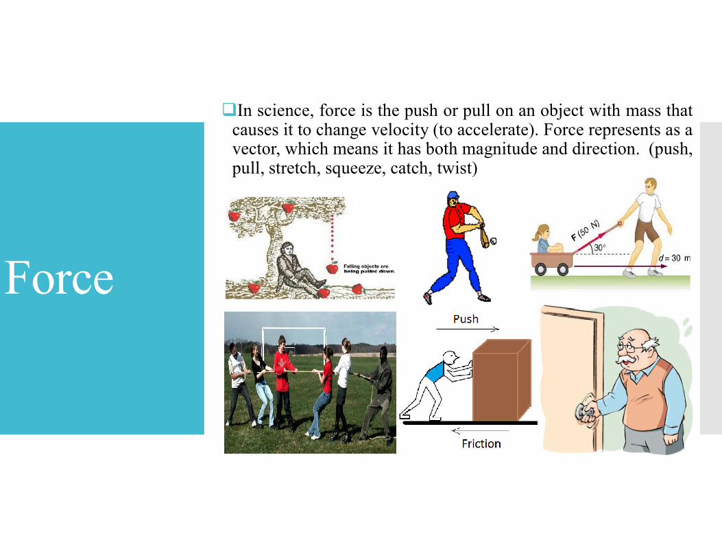
In science, force is the push or pull on an object with mass thatcauses it to change velocity (to accelerate). Force represents as avector, which means it has both magnitude and direction. (push,pull, stretch, squeeze, catch, twist)
Force Measurement
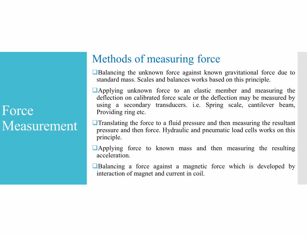
Methods of measuring forceBalancing the unknown force against known gravitational force due to
standard mass. Scales and balances works based on this principle.
Applying unknown force to an elastic member and measuring thedeflection on calibrated force scale or the deflection may be measured byusing a secondary transducers. i.e. Spring scale, cantilever beam,Providing ring etc.
Translating the force to a fluid pressure and then measuring the resultantpressure and then force. Hydraulic and pneumatic load cells works on thisprinciple.
Applying force to known mass and then measuring the resultingacceleration.
Balancing a force against a magnetic force which is developed byinteraction of magnet and current in coil.
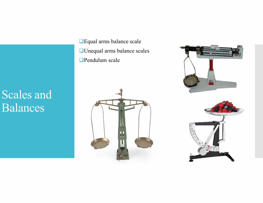
Scales and Balances
Equal arms balance scale
Unequal arms balance scales
Pendulum scale
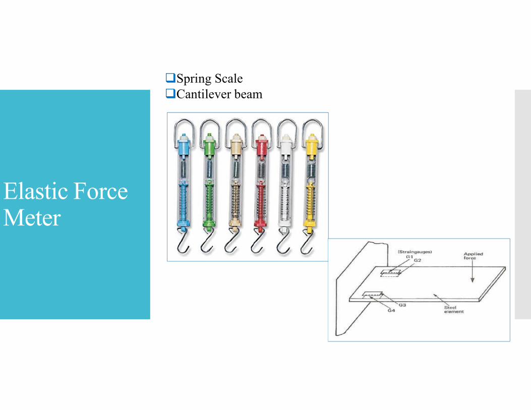
Elastic Force Meter
Spring ScaleCantilever beam
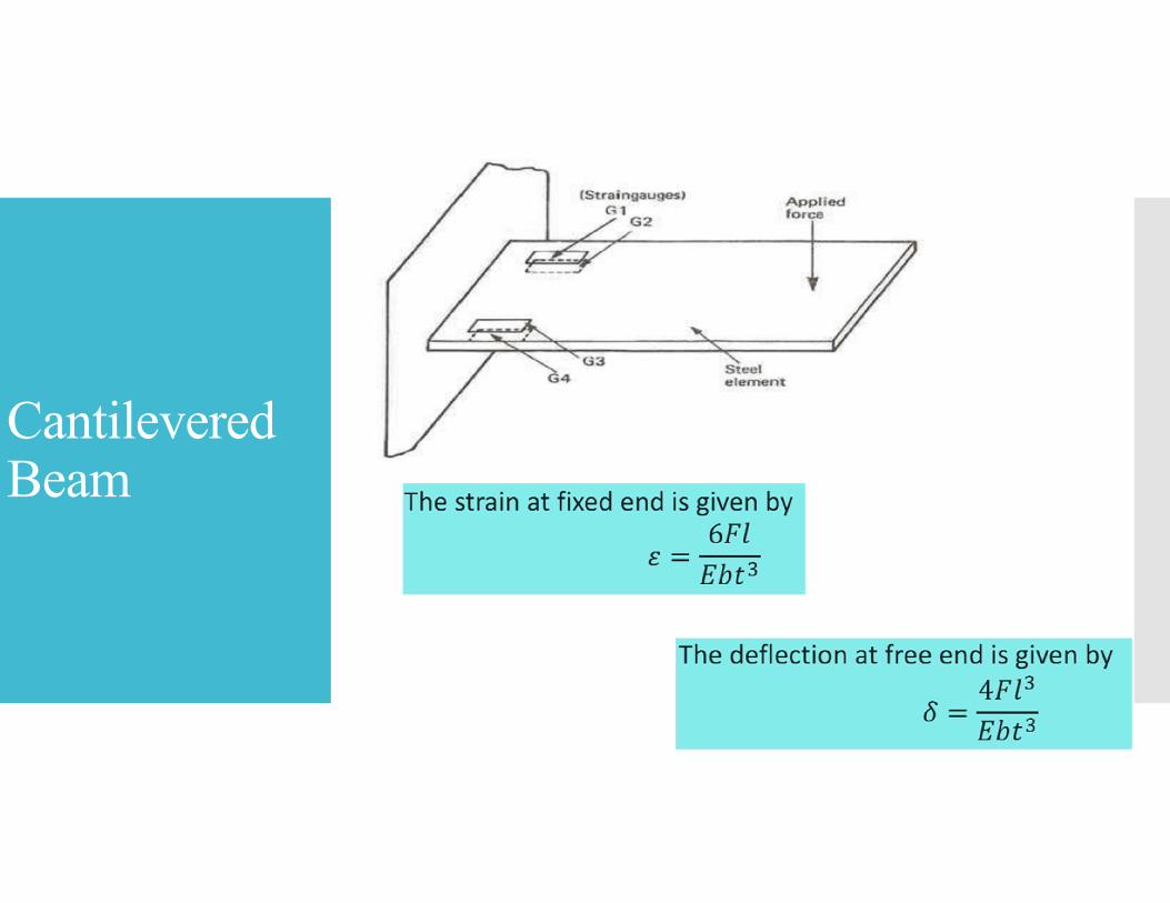
Cantilevered Beam
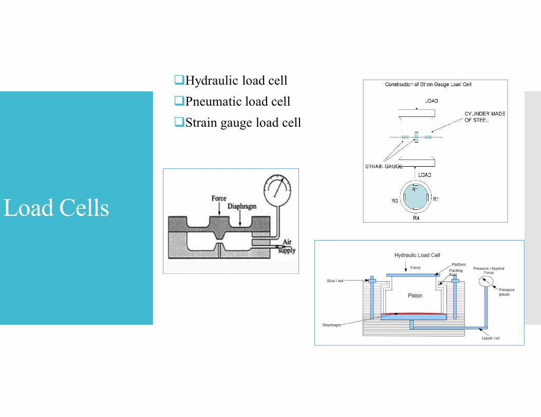
Load Cells
Hydraulic load cell
Pneumatic load cell
Strain gauge load cell
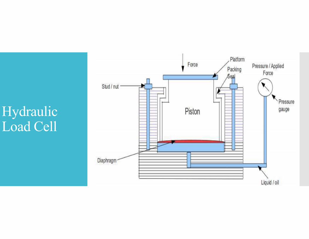
Hydraulic Load Cell
Hydraulic Load Cell
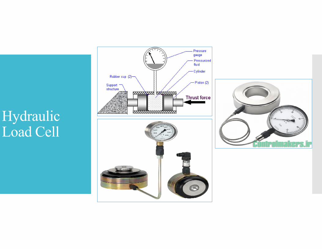
Basic Principle of Hydraulic Load cell
When a force is applied on a liquid medium contained in aconfined space, the pressure of the liquid increases.
This increase in pressure of the liquid is proportional to theapplied force.
Hence a measure of the increase in pressure of the liquidbecomes a measure of the applied force when calibrated.
Hydraulic Load Cell
Operation of Hydraulic Load Cell
The force to be measured is applied to the piston.
The applied force moves the piston downwards and deflects thediaphragm and this deflection of the diaphragm increases the pressure inthe liquid medium (oil).
This increase in pressure of the liquid medium is proportional to theapplied force.
The increase in pressure is measured by the pressure gauge which isconnected to the liquid medium.
The pressure is calibrated in force units and hence the indication in thepressure gauge becomes a measure of the force applied on the piston.
Hydraulic Load Cell
Pneumatic Load Cell
Pneumatic Load Cell
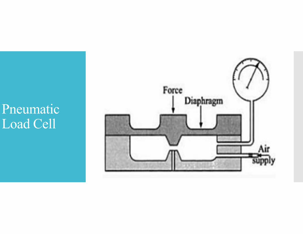
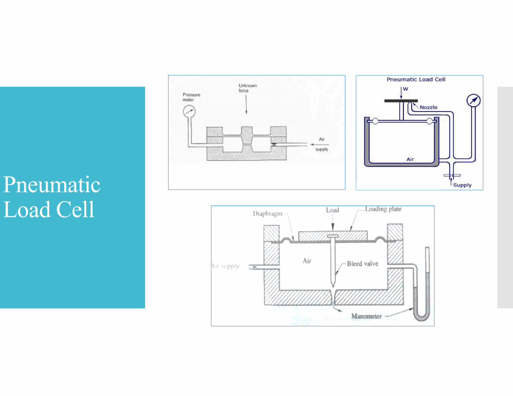
Pneumatic load cells also operate on force balance principle.
The force is applied to applied one side of a diaphragm offlexible material and balanced by pneumatic pressure on theother side.
The counteracting pressure is proportional to the force and isdisplayed on a pressure dial.
At this stage, the corresponding pressure indicated by thepressure gauge becomes a measure of the applied force whencalibrated.
Pneumatic Load Cell
Strain Gauge Load Cell
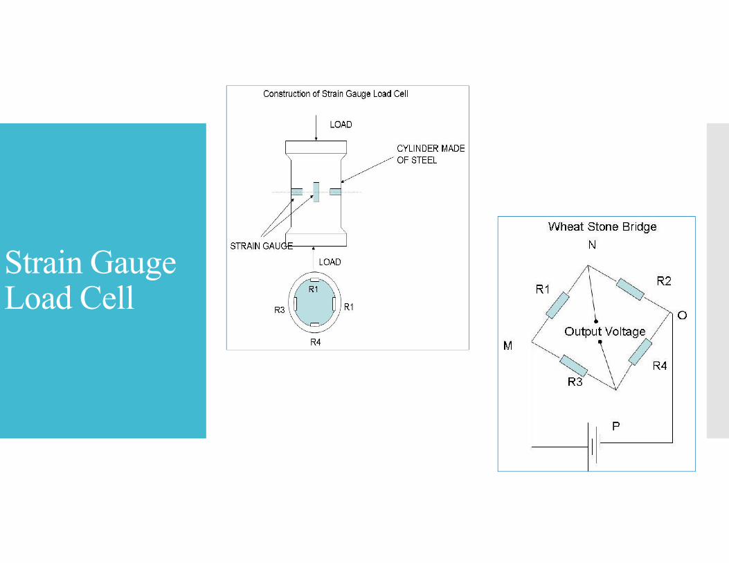
Strain Gauge Load Cell
When steel cylinder is subjected to a force, it tends to changein dimension.
On this cylinder, if the strain gauges are bonded, the straingauge also is stretched or compressed, causing a change in itslength and diameter.
This change in dimension of the strain gauge causes itsresistance to change.
This change in resistance or output voltage of the strain gaugebecomes a measure of applied force.

There are many other ways to measure theforce……..
Torque
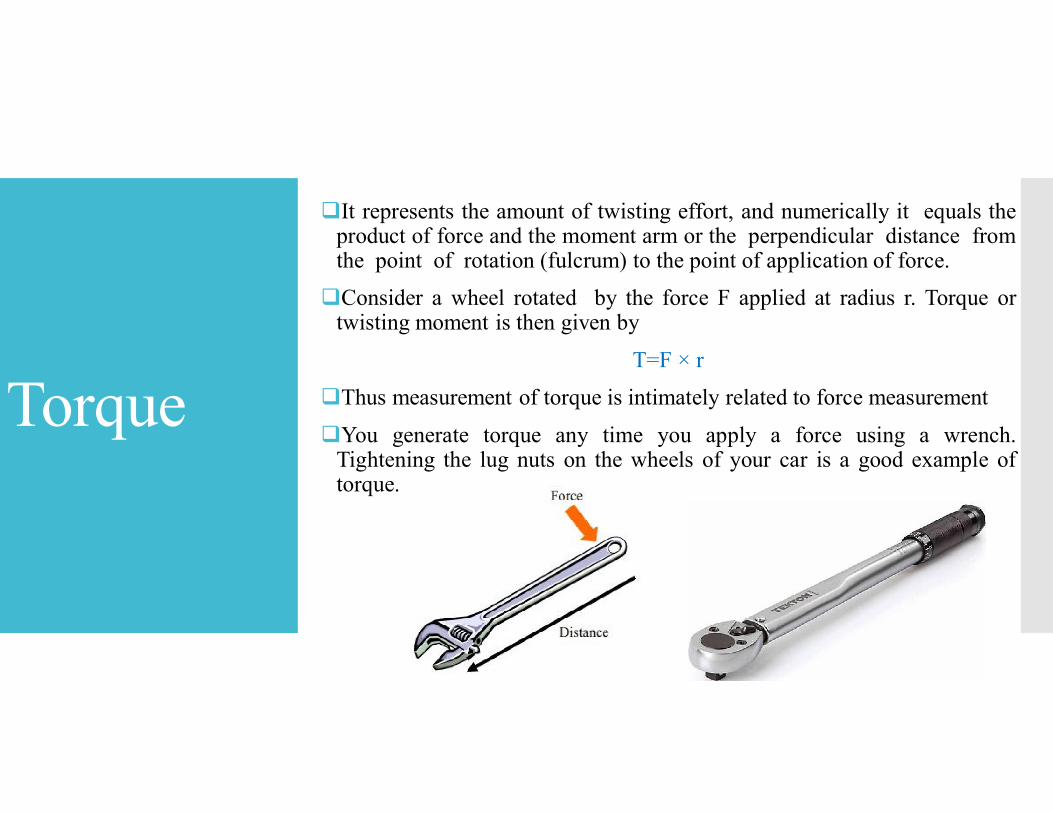
It represents the amount of twisting effort, and numerically it equals theproduct of force and the moment arm or the perpendicular distance fromthe point of rotation (fulcrum) to the point of application of force.
Consider a wheel rotated by the force F applied at radius r. Torque ortwisting moment is then given by
T=F × r
Thus measurement of torque is intimately related to force measurement
You generate torque any time you apply a force using a wrench.Tightening the lug nuts on the wheels of your car is a good example oftorque.
Torque Measurement
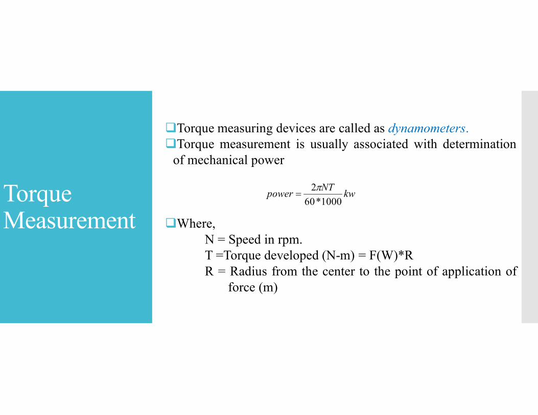
Torque measuring devices are called as dynamometers.Torque measurement is usually associated with determination
of mechanical power
Where,N = Speed in rpm.T =Torque developed (N-m) = F(W)*RR = Radius from the center to the point of application of
force (m)
kwNT
power1000*60
2
Torque Measurement(Types of Dynamometers)
Dynamometers can be broadly classified into two types.
Power Absorption Dynamometers: Power Absorptiondynamometers measure and absorb the power output of theengine to which they are coupled. The power absorbed isusually dissipated as heat by some means. Examples of powerabsorption dynamometers are Prony brake dynamometer, Ropebrake dynamometer, Eddy current dynamometer, Hydraulicdynamometer, etc.
Power Transmission Dynamometers: In power transmissiondynamometers the power is transmitted to the load coupled tothe engine after it is indicated on some scale. These are alsocalled torque meters.
Prony Brakes
Prony Brakes
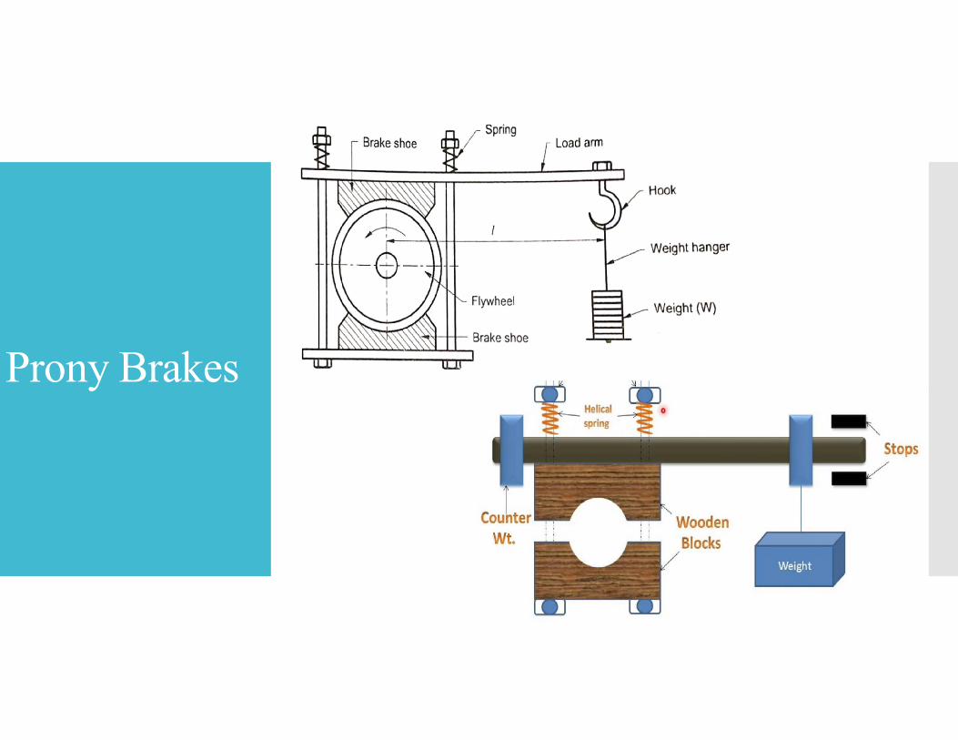
Prony Brake is one of the simplest dynamometers for measuring power
output (brake power).
It attempts to stop the engine using a brake on the flywheel and measure
the weight which an arm attached to the brake will support, as it tries to
rotate with the flywheel.
The Prony brake shown in the above consists of a wooden block, frame,
rope, brake shoes and flywheel.
It works on the principle of converting power into heat by dry friction.
Spring-loaded bolts are provided to increase the friction by tightening the
wooden block.
The whole of the power absorbed is converted into heat and hence this
type of dynamometer must the cooled.
The brake power is given by the formula
Brake Power (bp) = 2π NT
Where T = Weight applied (W) × distance (l)
Prony Brakes
Rope Brake Dynamometer
Rope Brake Dynamometer
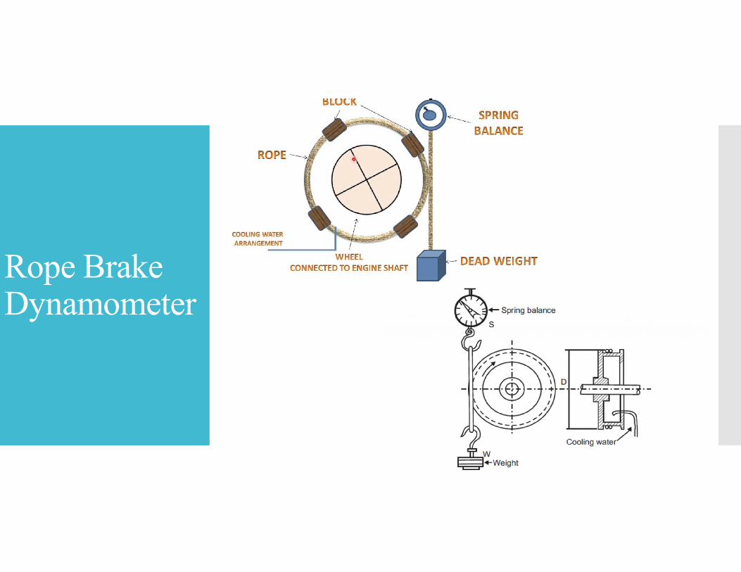
The rope brake as shown in figure is another device for measuring brakepower of an engine.
It consists of some turns of rope wound around the rotating drumattached to the output shaft.
One side of the rope is connected to a spring balance and the other sideto a loading device. The power is absorbed in friction between the ropeand the drum. Therefore drum in rope brake requires cooling.
Rope brake dynamometers are cheap and can be constructed quickly butbrake power can’t be measured accurately because of change inthe friction coefficient of the rope with a change in temperature.
The brake power is given by the formula
Brake Power (bp) = π DN (W − S)
Torque = (W-S)*R
where D is the brake drum diameter,
W is the weight of the load and
S is the spring balance reading.
Rope Brake Dynamometer
Hydraulic Dynamometer
Hydraulic Dynamometer
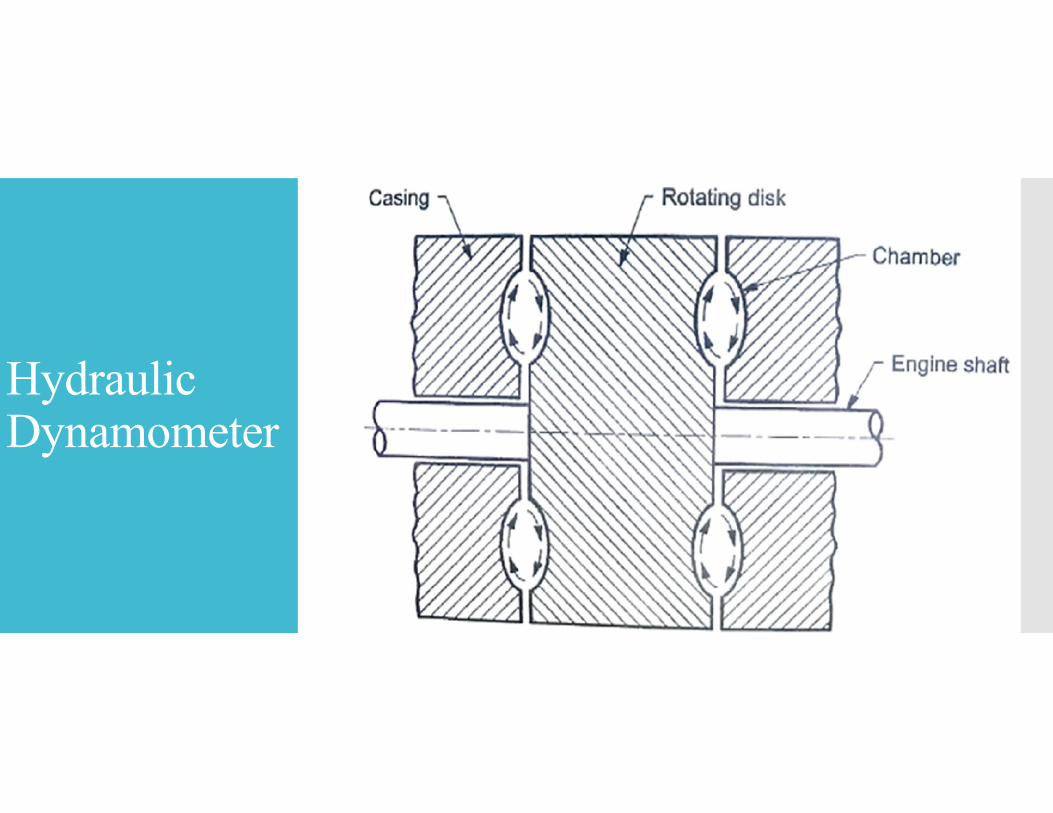
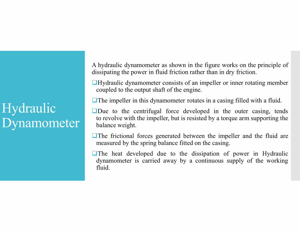
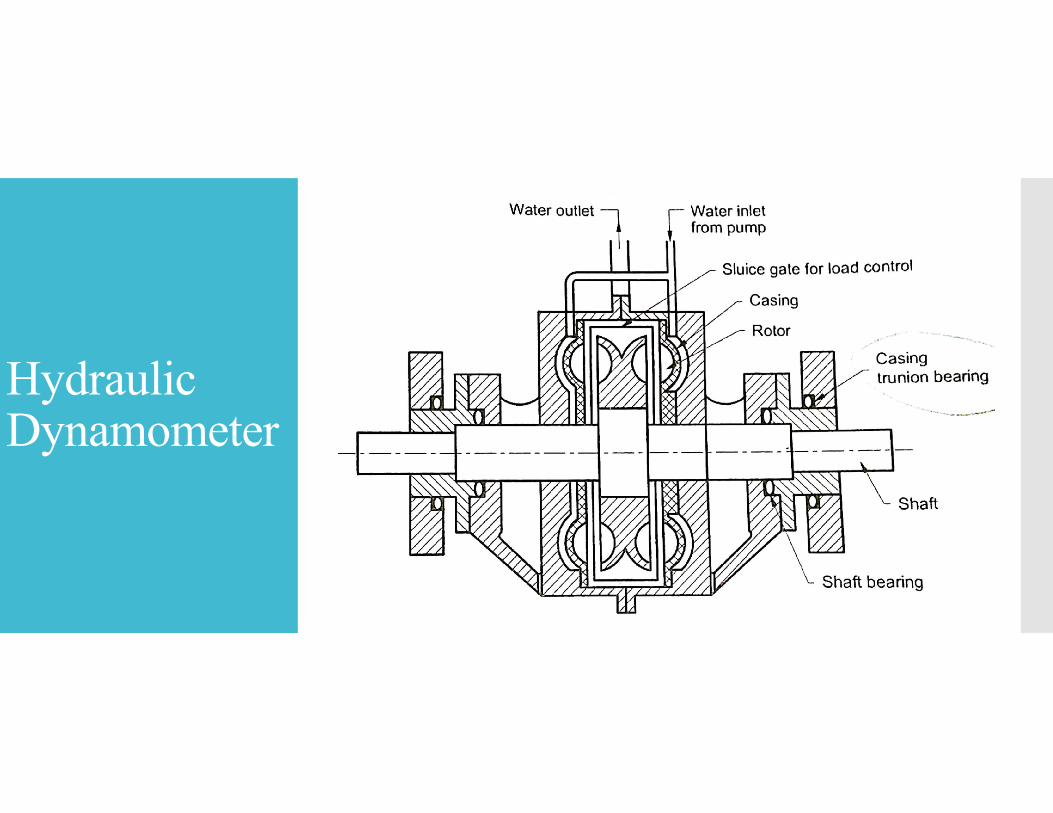
A hydraulic dynamometer as shown in the figure works on the principle ofdissipating the power in fluid friction rather than in dry friction.
Hydraulic dynamometer consists of an impeller or inner rotating membercoupled to the output shaft of the engine.
The impeller in this dynamometer rotates in a casing filled with a fluid.
Due to the centrifugal force developed in the outer casing, tendsto revolve with the impeller, but is resisted by a torque arm supporting thebalance weight.
The frictional forces generated between the impeller and the fluid aremeasured by the spring balance fitted on the casing.
The heat developed due to the dissipation of power in Hydraulicdynamometer is carried away by a continuous supply of the workingfluid.
Hydraulic Dynamometer

Eddy Current Dynamometer
Other Dynamometers
Epicyclical train dynamometer
Belt transmission dynamometer
Torsion dynamometer
Details: YouTube/Google

Thank You
Recommended