MECHANICAL INSTALLATION
OPERATION & MAINTENANCE
VPR Series VPRC/P Series
VPRE Series VPRX Series
IOM-M1-1214 Part Number 472916
VPR, VPRC/P, VPRE, VPRX Series IOM 2 IOM-M1-1214 Technical Support: (800) 789-8550 Part Number 472916
Table of Contents
Model Number Guide ...................................................................................... 3 Safety ..................................................................................................................... 4 Lifting Procedure .............................................................................................. 4 Clearances........................................................................................................... 6 Installation ........................................................................................................... 7
Pad Installation................................................................................................ 7 Curb Installation .............................................................................................. 7 Curb & Ductwork Dimensions .................................................................... 8
Outdoor Air Hood Assembly ..................................................................... 11 Duct & Drain Connections .......................................................................... 11
Condensate Drain Connection ................................................................. 11 Drain Sizes and Locations ......................................................................... 11 Duct Connections ......................................................................................... 12
Electrical, Gas, and Water Connections .............................................. 13 Pre-Punched Openings .............................................................................. 13 Electrical Connections ................................................................................ 15 Gas Connections .......................................................................................... 15 Refrigeration and Gas Connections – Indoor Unit ............................. 17 Pressure Testing the System ................................................................... 18 Chilled Water Coil Freeze Protection ..................................................... 18
Refrigeration System Setup ...................................................................... 19 Water Source Heat Pump.......................................................................... 19 Air Source Heat Pump ................................................................................ 21
Wiring .................................................................................................................. 22 Field-Mounted Sensors .............................................................................. 22
Maintenance ..................................................................................................... 24 Troubleshooting ............................................................................................. 28
Motor ................................................................................................................ 28 Blower .............................................................................................................. 28 Controls ........................................................................................................... 30
Startup Documentation ............................................................................... 32 Job Information ............................................................................................. 32 Startup Checklist .......................................................................................... 33 Air-Cooled Direct Expansion Startup Form .......................................... 34 Water Source Heat Pump Startup Form ............................................... 36 Air Source Heat Pump with Supplemental Heat Startup Form ...... 38
Cleaning Instructions for Enthalpy Plate ............................................. 41 Warranty ............................................................................................................. 42 Index .................................................................................................................... 43
Special Design Requests
VPR, VPRC/P, VPRE, and VPRX units are occasionally built with special features requested by the customer. This manual only covers standard options and does not include any Special Design Requests.
VPR, VPRC/P, VPRE, VPRX Series IOM 3 IOM-M1-1214 Technical Support: (800) 789-8550 Part Number 472916
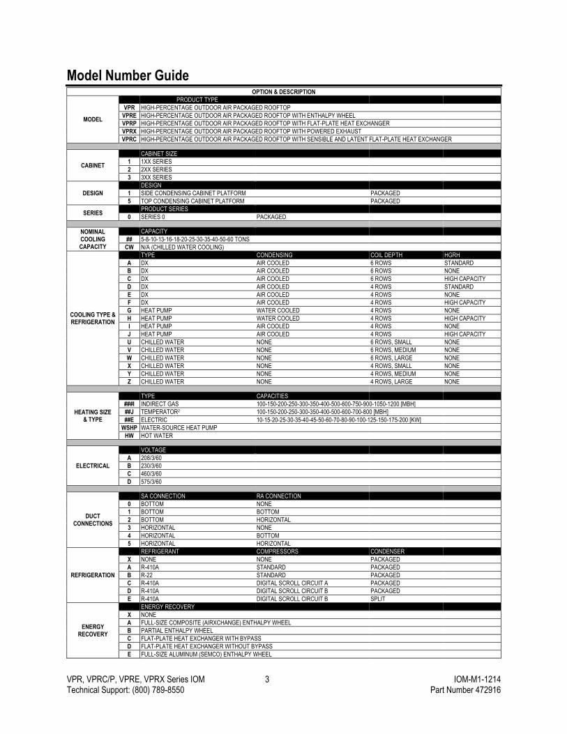
Model Number Guide OPTION & DESCRIPTION
MODEL
PRODUCT TYPE
VPR HIGH-PERCENTAGE OUTDOOR AIR PACKAGED ROOFTOP
VPRE HIGH-PERCENTAGE OUTDOOR AIR PACKAGED ROOFTOP WITH ENTHALPY WHEEL
VPRP HIGH-PERCENTAGE OUTDOOR AIR PACKAGED ROOFTOP WITH FLAT-PLATE HEAT EXCHANGER
VPRX HIGH-PERCENTAGE OUTDOOR AIR PACKAGED ROOFTOP WITH POWERED EXHAUST
VPRC HIGH-PERCENTAGE OUTDOOR AIR PACKAGED ROOFTOP WITH SENSIBLE AND LATENT FLAT-PLATE HEAT EXCHANGER
CABINET
CABINET SIZE
1 1XX SERIES
2 2XX SERIES
3 3XX SERIES
DESIGN
DESIGN
1 SIDE CONDENSING CABINET PLATFORM PACKAGED
5 TOP CONDENSING CABINET PLATFORM PACKAGED
SERIES PRODUCT SERIES
0 SERIES 0 PACKAGED
NOMINAL COOLING CAPACITY
CAPACITY
## 5-8-10-13-16-18-20-25-30-35-40-50-60 TONS
CW N/A (CHILLED WATER COOLING)
COOLING TYPE & REFRIGERATION
TYPE CONDENSING COIL DEPTH HGRH
A DX AIR COOLED 6 ROWS STANDARD
B DX AIR COOLED 6 ROWS NONE
C DX AIR COOLED 6 ROWS HIGH CAPACITY
D DX AIR COOLED 4 ROWS STANDARD
E DX AIR COOLED 4 ROWS NONE
F DX AIR COOLED 4 ROWS HIGH CAPACITY
G HEAT PUMP WATER COOLED 4 ROWS NONE
H HEAT PUMP WATER COOLED 4 ROWS HIGH CAPACITY
I HEAT PUMP AIR COOLED 4 ROWS NONE
J HEAT PUMP AIR COOLED 4 ROWS HIGH CAPACITY
U CHILLED WATER NONE 6 ROWS, SMALL NONE
V CHILLED WATER NONE 6 ROWS, MEDIUM NONE
W CHILLED WATER NONE 6 ROWS, LARGE NONE
X CHILLED WATER NONE 4 ROWS, SMALL NONE
Y CHILLED WATER NONE 4 ROWS, MEDIUM NONE
Z CHILLED WATER NONE 4 ROWS, LARGE NONE
HEATING SIZE & TYPE
TYPE CAPACITIES
###I INDIRECT GAS 100-150-200-250-300-350-400-500-600-750-900-1050-1200 [MBH]
##J TEMPERATOR2 100-150-200-250-300-350-400-500-600-700-800 [MBH]
##E ELECTRIC 10-15-20-25-30-35-40-45-50-60-70-80-90-100-125-150-175-200 [KW]
WSHP WATER-SOURCE HEAT PUMP
HW HOT WATER
ELECTRICAL
VOLTAGE
A 208/3/60
B 230/3/60
C 460/3/60
D 575/3/60
DUCT CONNECTIONS
SA CONNECTION RA CONNECTION
0 BOTTOM NONE
1 BOTTOM BOTTOM
2 BOTTOM HORIZONTAL
3 HORIZONTAL NONE
4 HORIZONTAL BOTTOM
5 HORIZONTAL HORIZONTAL
REFRIGERATION
REFRIGERANT COMPRESSORS CONDENSER
X NONE NONE PACKAGED
A R-410A STANDARD PACKAGED
B R-22 STANDARD PACKAGED
C R-410A DIGITAL SCROLL CIRCUIT A PACKAGED
D R-410A DIGITAL SCROLL CIRCUIT B PACKAGED
E R-410A DIGITAL SCROLL CIRCUIT B SPLIT
ENERGY RECOVERY
ENERGY RECOVERY
X NONE
A FULL-SIZE COMPOSITE (AIRXCHANGE) ENTHALPY WHEEL
B PARTIAL ENTHALPY WHEEL
C FLAT-PLATE HEAT EXCHANGER WITH BYPASS
D FLAT-PLATE HEAT EXCHANGER WITHOUT BYPASS
E FULL-SIZE ALUMINUM (SEMCO) ENTHALPY WHEEL
VPR, VPRC/P, VPRE, VPRX Series IOM 4 IOM-M1-1214 Technical Support: (800) 789-8550 Part Number 472916
Safety
WARNING:
Improper installation, adjustment, service, maintenance, or alteration can cause property damage, personal injury, or loss of life. Installation, startup, and service must be performed by a qualified installer, service agency, or gas supplier.
The customer must provide proper equipment and fully-trained installers to follow local safety requirements when receiving, installing, or
servicing equipment. Consult all local building, electrical, occupational safety, and gas codes.
Lock out all power supplies before servicing the unit to prevent accidental startup. All fan blades should be secured to prevent wind rotation. Remove any restrictive device before restoring power.
The Clean Air Act of 1990 bans the intentional venting of refrigerant (CFC and HCFC) as of July 1, 1992. Approved methods of recovery, recycling, or reclaiming refrigerant must be followed. Fines and/or incarceration may be levied for non-compliance.
Lifting Procedure
Lifting Guidelines
▪ Crane lift only.
▪ Preparation of curb and roof openings should be completed prior to lifting unit to the roof.
▪ Lifting lugs consist of integral U-bolts located at the top of the unit.
▪ Unit must be lifted using all lifting lugs on the exterior of the unit.
▪ Cables or chains should be at least double the length of the unit to prevent stress on the structure.
▪ Spreader bars are required for lifting the unit to prevent damage to the cabinet.
▪ Do not use belt-type slings.
▪ Chain angle at point of lug connection must never exceed 20 degrees from vertical in any direction.
▪ Always test-lift the unit to check for proper balance and rigging before hoisting to desired location.
▪ Do not twist the unit while it is being lifted.
WARNING:
Failure to follow proper instructions could result in property damage, serious injury, or death. Never lift units in windy conditions.
Lifting Lug Quantities
Casing VPR VPRX VPRE VPRC/P
110 4 4 6 8
210 4 4 6 8
310 4 4 6 8
350 6 6 8 10
VPR, VPRC/P, VPRE, VPRX Series IOM 5 IOM-M1-1214 Technical Support: (800) 789-8550 Part Number 472916
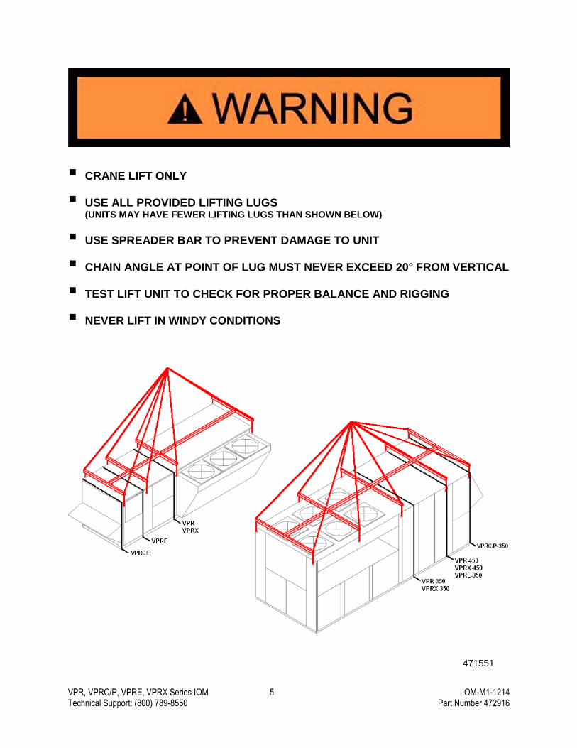
CRANE LIFT ONLY
USE ALL PROVIDED LIFTING LUGS (UNITS MAY HAVE FEWER LIFTING LUGS THAN SHOWN BELOW)
USE SPREADER BAR TO PREVENT DAMAGE TO UNIT
CHAIN ANGLE AT POINT OF LUG MUST NEVER EXCEED 20° FROM VERTICAL
TEST LIFT UNIT TO CHECK FOR PROPER BALANCE AND RIGGING
NEVER LIFT IN WINDY CONDITIONS
471551
VPR, VPRC/P, VPRE, VPRX Series IOM 6 IOM-M1-1214 Technical Support: (800) 789-8550 Part Number 472916
Clearances
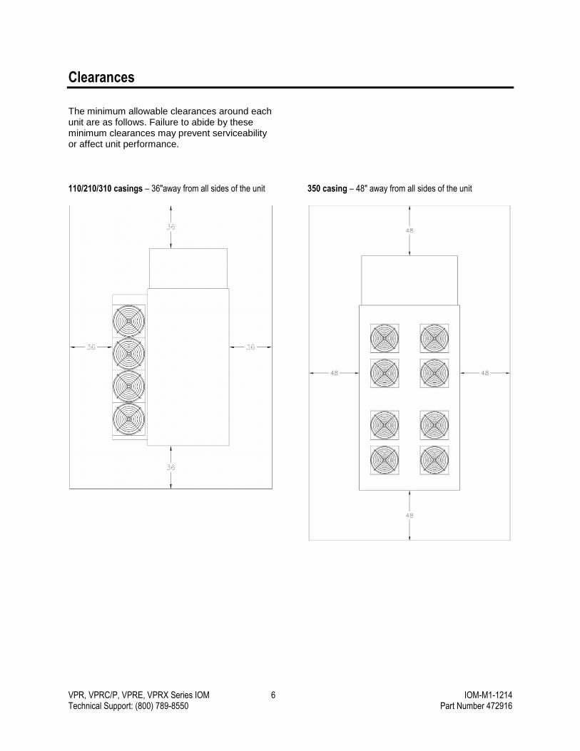
The minimum allowable clearances around each unit are as follows. Failure to abide by these minimum clearances may prevent serviceability or affect unit performance.
110/210/310 casings – 36"away from all sides of the unit
350 casing – 48" away from all sides of the unit
VPR, VPRC/P, VPRE, VPRX Series IOM 7 IOM-M1-1214 Technical Support: (800) 789-8550 Part Number 472916
Installation
Receiving and Inspection Visually inspect the unit before unloading and note any damage in writing on the delivery receipt. If the unit is damaged during shipping, the customer should immediately file a claim with the shipping company and notify the manufacturer. Photograph the damage if possible.
Verify that all pieces listed on the bill of lading have been received.
Storage Any unit stored outdoors prior to installation should be covered. Do not store other equipment on top of or inside the unit.
Temporary Use This equipment must not be used as:
Temporary heating or cooling
Construction heating
The units should not be operated until construction is complete and the units have properly undergone the pre-startup and startup routines.
IMPORTANT: The bottom of the unit must be field-insulated if outdoor air can contact the bottom of the unit. To avoid leakage, do not drill or punch holes in the floor of the unit.
Hanging Installation DO NOT permanently suspend the unit from the lifting lugs. If the unit is to be hung, additional supports are required under the unit. Hang the unit from the supports, making sure the unit is level. Failure to keep the unit level will result in operational problems.
Pad Installation
▪ Check to make sure the pad is level. Failure to provide a level surface will result in operational problems.
▪ Check for correct orientation of the unit.
▪ Lift unit into place per the lifting instructions in this manual.
▪ Secure the unit to the pad in accordance with all applicable building codes.
▪ Tighten door handles.
Curb Installation
IMPORTANT: Gasket material must be applied to all surfaces of the curb which contact the unit to create proper seal between the unit and the curb.
▪ Ensure that the roof curb is level. Failure to level the curb will result in operational problems.
▪ Lift unit into place per the lifting instructions in this manual.
▪ Ensure a neoprene gasket is installed on the top flange of the perimeter and cross members of the curb.
▪ Check for correct orientation of the unit on the curb.
▪ Check the seal between the roof curb and the unit. Apply additional caulking as required. Failure to provide an adequate seal can result in air and water leakage into the building.
▪ Secure the unit to the curb in accordance with all applicable building codes.
▪ Tighten door handles.
Specifications Factory-supplied roof curbs shall be constructed of 16 gauge G-90 galvanized steel and fully assembled at the factory. A 1.5" wood nailer shall be provided around the entire perimeter of the curb. Curb shall be fully insulated through 1.5" fiberglass insulation. Cross-member supports shall be provided for connecting ductwork prior to the unit being set on the roof.
Duct Connections to Curb When the supply air discharge opening and/or the return air intake opening are located on the bottom of a VPR, VPRC/P, VPRE, or VPRX series unit, the ductwork should be connected to the curb directly. The actual opening sizes in the floor of the unit are not specified as they are slightly undersized from the duct dimensions shown on the following curb drawings.
VPR, VPRC/P, VPRE, VPRX Series IOM 8 IOM-M1-1214 Technical Support: (800) 789-8550 Part Number 472916
Curb & Ductwork Dimensions
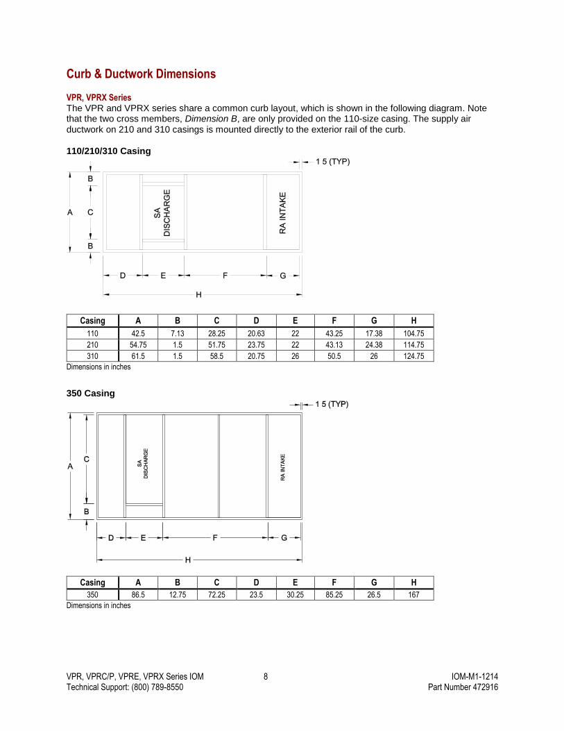
VPR, VPRX Series The VPR and VPRX series share a common curb layout, which is shown in the following diagram. Note that the two cross members, Dimension B, are only provided on the 110-size casing. The supply air ductwork on 210 and 310 casings is mounted directly to the exterior rail of the curb.
110/210/310 Casing
Casing A B C D E F G H
110 42.5 7.13 28.25 20.63 22 43.25 17.38 104.75
210 54.75 1.5 51.75 23.75 22 43.13 24.38 114.75
310 61.5 1.5 58.5 20.75 26 50.5 26 124.75
Dimensions in inches
350 Casing
Casing A B C D E F G H
350 86.5 12.75 72.25 23.5 30.25 85.25 26.5 167
Dimensions in inches

VPR, VPRC/P, VPRE, VPRX Series IOM 9 IOM-M1-1214 Technical Support: (800) 789-8550 Part Number 472916
VPRE Series The VPRE series is constructed with a cross member in the base that requires one of the following when curb mounted:
Partial-perimeter curb plus secondary support rails (standard factory offering) Partial-perimeter curb plus equipment support Single curb with 6" x 6" notch(es) to accommodate cross members in 1 to 2 locations depending on
unit configuration VPRE-350 one-piece curb does not include a 6"x6" notch
110/210/310 Casing
Casing A B C D E F G H I
J K
Bottom RA Side RA Bottom RA Side RA
110 42.5 7.13 28.25 20.63 22 43.25 17.38 104.75 12 39 36 152.75 179.75
210 54.75 1.5 51.75 23.75 22 43.13 24.38 114.75 12 39 36 162.75 189.75
310 61.5 1.5 58.5 20.75 26 50.5 26 124.75 12 39 36 172.75 199.75
Dimensions in inches
350 Casing
Casing A B C D E F G H I
350 86.5 12.75 72.25 23.5 30.25 85.25 26.5 73.5 239
Dimensions in inches

VPR, VPRC/P, VPRE, VPRX Series IOM 10 IOM-M1-1214 Technical Support: (800) 789-8550 Part Number 472916
VPRC/P Series The VPRC/P series is constructed with a cross member in the base that requires one of the following when curb mounted:
Partial-perimeter curb plus secondary support rails (standard factory offering) Partial-perimeter curb plus equipment support Single curb with 6" x 6" notch(es) to accommodate cross members in 1 to 2 locations depending on
unit configuration VPRC/P-350 one-piece curb does not include a 6"x6" notch
110/210/310 Casing
Casing A B C D E F G H I
J K
Bottom RA Side RA Bottom RA Side RA
110 42.5 7.13 28.25 20.63 22 43.25 17.38 104.75 12 39 67 183.75 210.75
210 54.75 1.5 51.75 23.75 22 43.13 24.38 114.75 12 39 67 193.75 220.75
310 61.5 1.5 58.5 20.75 26 50.5 26 124.75 12 39 67 203.75 230.75
Dimensions in inches
350 Casing
Casing A B C D E F G H I
350 86.5 12.75 72.25 23.5 30.25 85.25 26.5 119.5 285
Dimensions in inches
VPR, VPRC/P, VPRE, VPRX Series IOM 11 IOM-M1-1214 Technical Support: (800) 789-8550 Part Number 472916
Outdoor Air Hood Assembly
Please refer to the Outdoor Air Hood Assembly Instructions, part number 476059, for information about assembling the outdoor air hood that is shipped with the unit.
Duct & Drain Connections
Condensate Drain Connection
All condensate drain connections must be properly trapped and primed before operating the unit. Failure to properly trap a drain will result in flooding the drain pan and potential water damage to the unit or building.
Slope the piping from the trap downward in direction of flow. The trap must be primed before startup by filling the U portion of the trap with water. Drains that are not properly trapped and primed will not operate correctly. Each drain connection must be individually trapped.
Drains that are inactive will dry out and air will be drawn through the drain, preventing water flow. Inactive drains should be plugged or connected to a shutoff valve. On outdoor units that operate during freezing weather, install a heat trace around trap piping. Refer to the following figure to determine the correct trap height.
N=Negative Fan Pressure (InWc)
H=N+[1InWc (minimum)]
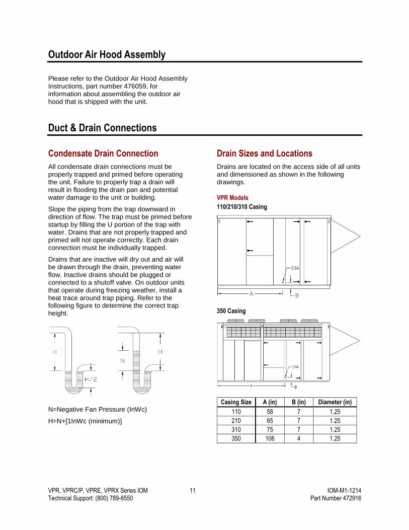
Drain Sizes and Locations
Drains are located on the access side of all units and dimensioned as shown in the following drawings.
VPR Models
110/210/310 Casing
350 Casing
Casing Size A (in) B (in) Diameter (in)
110 58 7 1.25
210 65 7 1.25
310 75 7 1.25
350 106 4 1.25
VPR, VPRC/P, VPRE, VPRX Series IOM 12 IOM-M1-1214 Technical Support: (800) 789-8550 Part Number 472916
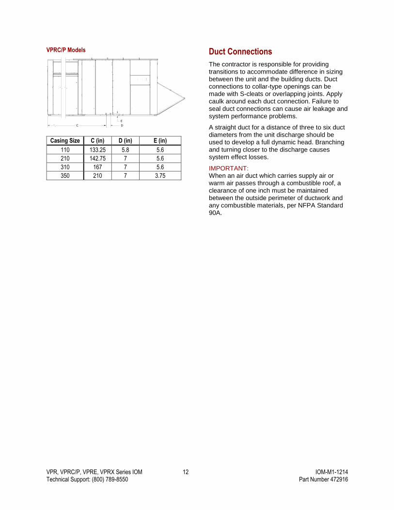
VPRC/P Models
Casing Size C (in) D (in) E (in)
110 133.25 5.8 5.6
210 142.75 7 5.6
310 167 7 5.6
350 210 7 3.75
Duct Connections
The contractor is responsible for providing transitions to accommodate difference in sizing between the unit and the building ducts. Duct connections to collar-type openings can be made with S-cleats or overlapping joints. Apply caulk around each duct connection. Failure to seal duct connections can cause air leakage and system performance problems.
A straight duct for a distance of three to six duct diameters from the unit discharge should be used to develop a full dynamic head. Branching and turning closer to the discharge causes system effect losses.
IMPORTANT: When an air duct which carries supply air or warm air passes through a combustible roof, a clearance of one inch must be maintained between the outside perimeter of ductwork and any combustible materials, per NFPA Standard 90A.
C D
E
DIM 110 210 310 350C 133.25 142.75 167.00 210D 5.8 7.0 7.0 7.0E 5.6 5.6 5.6 3.75
VPRC/P DRAIN LOCATIONS(REVISED FOR NEW HX SECTION)
VPR, VPRC/P, VPRE, VPRX Series IOM 13 IOM-M1-1214 Technical Support: (800) 789-8550 Part Number 472916
Electrical, Gas, and Water Connections
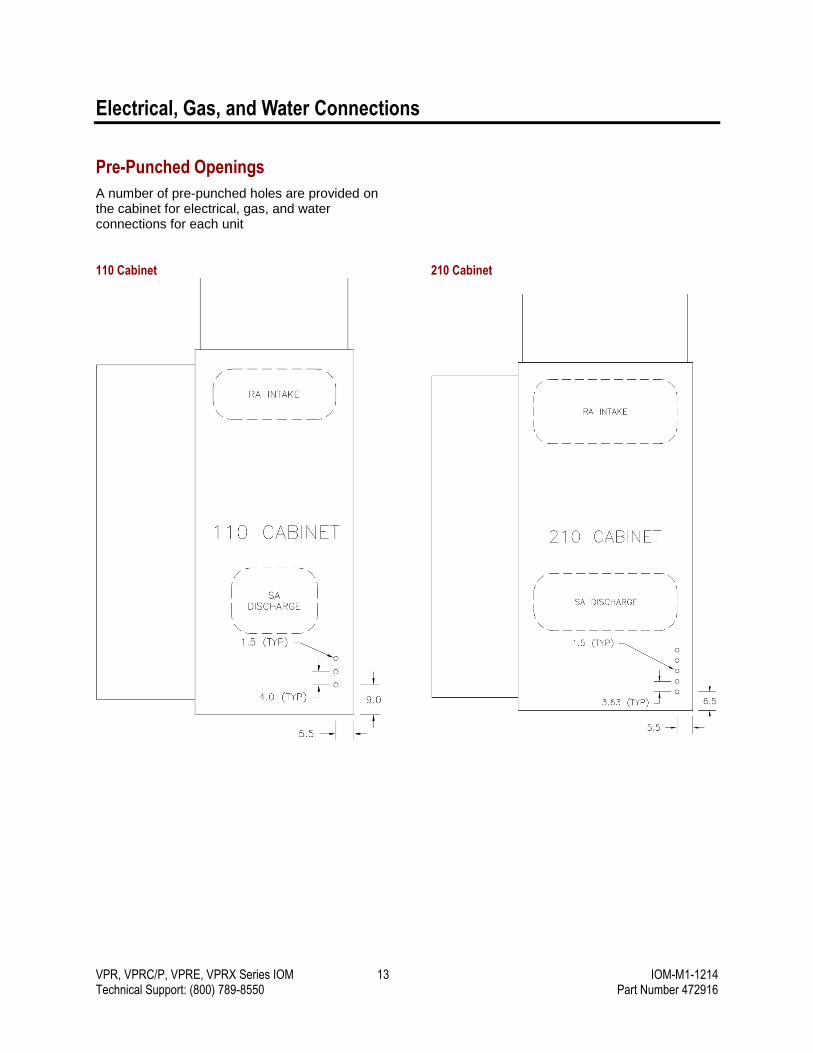
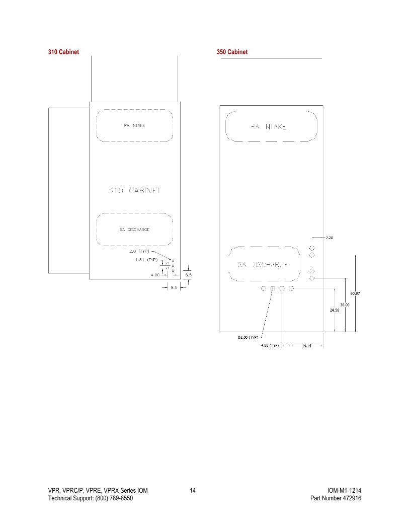
Pre-Punched Openings
A number of pre-punched holes are provided on the cabinet for electrical, gas, and water connections for each unit
110 Cabinet
210 Cabinet
VPR, VPRC/P, VPRE, VPRX Series IOM 14 IOM-M1-1214 Technical Support: (800) 789-8550 Part Number 472916
310 Cabinet
350 Cabinet
VPR, VPRC/P, VPRE, VPRX Series IOM 15 IOM-M1-1214 Technical Support: (800) 789-8550 Part Number 472916
Electrical Connections
All electrical connections should be made in accordance with local building codes. Wiring may be drawn through the base of the unit using the pre-punched openings.
Gas Connections
Gas pipe must be sized and installed in accordance with applicable codes and by qualified personnel. Authorities having jurisdiction should be consulted before installing and connecting gas lines.
Gas furnaces are designed for gas pressure of 5-13.5 InWc for natural gas (6″ minimum on single 500 and 600 MBH furnaces) and 11-13.5 InWc for LP. If the gas pressure at the job location is greater than 13.5 InWc, an additional regulator is required to reduce pressure.
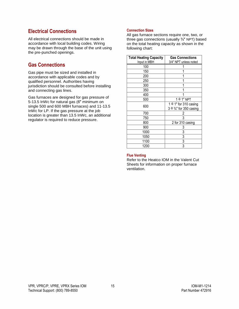
Connection Sizes All gas furnace sections require one, two, or three gas connections (usually ¾″ NPT) based on the total heating capacity as shown in the following chart:
Total Heating Capacity Input in MBH
Gas Connections 3/4" NPT unless noted
100 1
150 1
200 1
250 1
300 1
350 1
400 1
500 1 @ 1″ NPT
600 1 @ 1″ for 310 casing 3 @ ¾″ for 350 casing
700 2
750 3
800 2 for 310 casing
900 3
1000 3
1050 3
1100 3
1200 3
Flue Venting Refer to the Heatco IOM in the Valent Cut Sheets for information on proper furnace ventilation.
VPR, VPRC/P, VPRE, VPRX Series IOM 16 IOM-M1-1214 Technical Support: (800) 789-8550 Part Number 472916
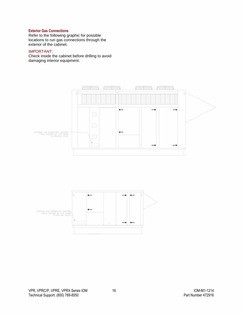
Exterior Gas Connections Refer to the following graphic for possible locations to run gas connections through the exterior of the cabinet.
IMPORTANT: Check inside the cabinet before drilling to avoid damaging interior equipment.

VPR, VPRC/P, VPRE, VPRX Series IOM 17 IOM-M1-1214 Technical Support: (800) 789-8550 Part Number 472916
Refrigeration and Gas Connections – Indoor Unit
The following diagrams illustrate suggested field refrigerant piping penetrations as well as furnace flue duct connections when equipped with IG heat.
Hatched area represents general location of refrigerant piping penetrations.
110 – All Furnaces
310 – 400 MBH Furnace
210 – All Furnaces
310 – 500-800 MBH Furnaces
VPR, VPRC/P, VPRE, VPRX Series IOM 18 IOM-M1-1214 Technical Support: (800) 789-8550 Part Number 472916
Pressure Testing the System
When test pressures exceed 14 InWc, the heater must be disconnected from the supply gas piping.
When test pressures are 14 InWc or less, the heater must be isolated from the supply gas piping by closing its individual manual shutoff valve.
The gas pressure to the unit should be checked to make sure that the gas pressure does not fall out-side of the maximum and minimum allowable gas pressures listed on the unit nameplate.
For your safety, if you smell gas:
Open windows
Don’t touch electrical switches
Extinguish any open flame
Vacate the area
Immediately call your gas supplier
IMPORTANT: Check both the supply lines and factory piping for leaks. Apply a soap and water solution to all piping and watch for bubbling. Some soaps used for leak detection are corrosive to some metals. Carefully rinse to remove soap and clean the pipe after leak test is completed.
VPR, VPRC/P, VPRE, and VPRX series units use furnaces from two manufacturers. Verify which furnace is in the unit and consult the appropriate manual.
Chilled Water Coil Freeze Protection
Chilled water coils must be protected against freezing when the ambient temperature is less than 40°F. Either a suitable antifreeze solution (glycol) can be used in the coil or the coil can be drained. Vent and drain connections are provided for coil drainage. The coil must be completely drained using air or nitrogen
pressure to blow any remaining water from the coil. Failure to properly protect the coil from freezing may result in damage to coil and property.
A freeze stat is provided on chilled water coils to prevent the unit from operating during freezing conditions. This is not a failsafe method of freeze protection, and the coil must still be protected by one of the above means. To prevent nuisance trips on chilled water coils with glycol, the freeze stat setpoint must be lowered to the freezing point of the water/glycol mix.
WARNING:
Fuel gas poses a danger of explosion which can cause personal injury, product damage, or property damage. Do not use matches, candles, flame, of other sources of ignition to check for leaks.
WARNING:
Gas-fired equipment is designed to provide safe, controlled combustion. The installer must ensure that the correct amount of supply combustion air and a properly operating vent system is provided. If the installation does not permit the burner to receive the proper supply of combustion air, complete combustion may not occur and carbon monoxide may be produced.
WARNING:
Carbon monoxide is a lethal, colorless, odorless gas.
VPR, VPRC/P, VPRE, VPRX Series IOM 19 IOM-M1-1214 Technical Support: (800) 789-8550 Part Number 472916
Refrigeration System Setup
Water Source Heat Pump
Each refrigeration circuit on ventilators with the water source heat pump refrigeration option includes a coaxial water-to-refrigerant heat exchanger. In addition, a two- or three-way valve with modulating actuator is provided with each circuit for refrigerant pressure control.
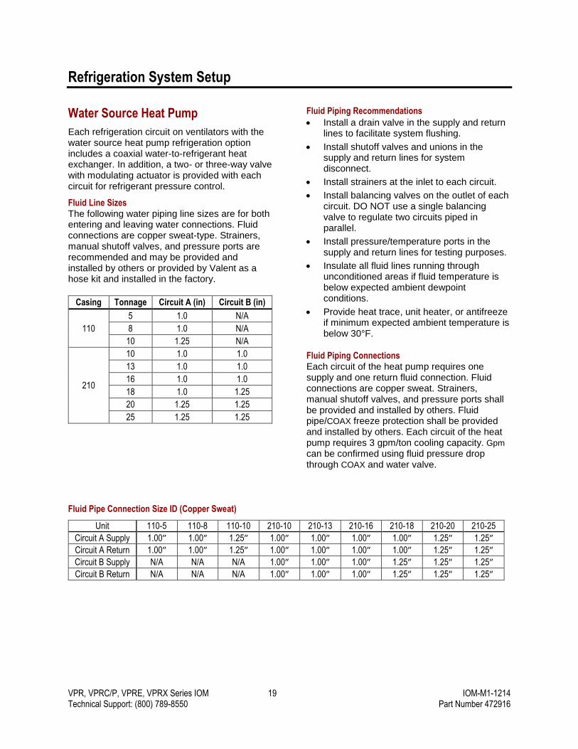
Fluid Line Sizes The following water piping line sizes are for both entering and leaving water connections. Fluid connections are copper sweat-type. Strainers, manual shutoff valves, and pressure ports are recommended and may be provided and installed by others or provided by Valent as a hose kit and installed in the factory.
Casing Tonnage Circuit A (in) Circuit B (in)
110
5 1.0 N/A
8 1.0 N/A
10 1.25 N/A
210
10 1.0 1.0
13 1.0 1.0
16 1.0 1.0
18 1.0 1.25
20 1.25 1.25
25 1.25 1.25
Fluid Piping Recommendations
Install a drain valve in the supply and return lines to facilitate system flushing.
Install shutoff valves and unions in the supply and return lines for system disconnect.
Install strainers at the inlet to each circuit.
Install balancing valves on the outlet of each circuit. DO NOT use a single balancing valve to regulate two circuits piped in parallel.
Install pressure/temperature ports in the supply and return lines for testing purposes.
Insulate all fluid lines running through unconditioned areas if fluid temperature is below expected ambient dewpoint conditions.
Provide heat trace, unit heater, or antifreeze if minimum expected ambient temperature is below 30°F.
Fluid Piping Connections Each circuit of the heat pump requires one supply and one return fluid connection. Fluid connections are copper sweat. Strainers, manual shutoff valves, and pressure ports shall be provided and installed by others. Fluid pipe/COAX freeze protection shall be provided and installed by others. Each circuit of the heat pump requires 3 gpm/ton cooling capacity. Gpm can be confirmed using fluid pressure drop through COAX and water valve.
Fluid Pipe Connection Size ID (Copper Sweat)
Unit 110-5 110-8 110-10 210-10 210-13 210-16 210-18 210-20 210-25
Circuit A Supply 1.00″ 1.00″ 1.25″ 1.00″ 1.00″ 1.00″ 1.00″ 1.25″ 1.25″
Circuit A Return 1.00″ 1.00″ 1.25″ 1.00″ 1.00″ 1.00″ 1.00″ 1.25″ 1.25″
Circuit B Supply N/A N/A N/A 1.00″ 1.00″ 1.00″ 1.25″ 1.25″ 1.25″
Circuit B Return N/A N/A N/A 1.00″ 1.00″ 1.00″ 1.25″ 1.25″ 1.25″
VPR, VPRC/P, VPRE, VPRX Series IOM 20 IOM-M1-1214 Technical Support: (800) 789-8550 Part Number 472916
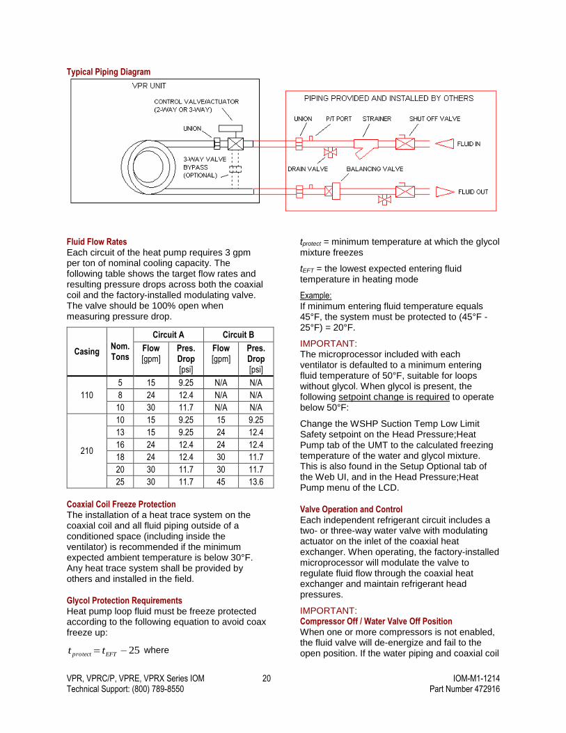
Typical Piping Diagram
Fluid Flow Rates Each circuit of the heat pump requires 3 gpm per ton of nominal cooling capacity. The following table shows the target flow rates and resulting pressure drops across both the coaxial coil and the factory-installed modulating valve. The valve should be 100% open when measuring pressure drop.
Casing Nom. Tons
Circuit A Circuit B
Flow [gpm]
Pres. Drop [psi]
Flow [gpm]
Pres. Drop [psi]
110
5 15 9.25 N/A N/A
8 24 12.4 N/A N/A
10 30 11.7 N/A N/A
210
10 15 9.25 15 9.25
13 15 9.25 24 12.4
16 24 12.4 24 12.4
18 24 12.4 30 11.7
20 30 11.7 30 11.7
25 30 11.7 45 13.6
Coaxial Coil Freeze Protection The installation of a heat trace system on the coaxial coil and all fluid piping outside of a conditioned space (including inside the ventilator) is recommended if the minimum expected ambient temperature is below 30°F. Any heat trace system shall be provided by others and installed in the field.
Glycol Protection Requirements Heat pump loop fluid must be freeze protected according to the following equation to avoid coax freeze up:
25 EFTprotect tt where
tprotect = minimum temperature at which the glycol mixture freezes
tEFT = the lowest expected entering fluid temperature in heating mode
Example: If minimum entering fluid temperature equals 45°F, the system must be protected to (45°F - 25°F) = 20°F.
IMPORTANT: The microprocessor included with each ventilator is defaulted to a minimum entering fluid temperature of 50°F, suitable for loops without glycol. When glycol is present, the following setpoint change is required to operate below 50°F:
Change the WSHP Suction Temp Low Limit Safety setpoint on the Head Pressure;Heat Pump tab of the UMT to the calculated freezing temperature of the water and glycol mixture. This is also found in the Setup Optional tab of the Web UI, and in the Head Pressure;Heat Pump menu of the LCD.
Valve Operation and Control Each independent refrigerant circuit includes a two- or three-way water valve with modulating actuator on the inlet of the coaxial heat exchanger. When operating, the factory-installed microprocessor will modulate the valve to regulate fluid flow through the coaxial heat exchanger and maintain refrigerant head pressures.
IMPORTANT: Compressor Off / Water Valve Off Position When one or more compressors is not enabled, the fluid valve will de-energize and fail to the open position. If the water piping and coaxial coil
VPR, VPRC/P, VPRE, VPRX Series IOM 21 IOM-M1-1214 Technical Support: (800) 789-8550 Part Number 472916
are equipped with heat trace or the fluid contains glycol, the valve may be set to a position by modifying any of these setpoints:
WSHP Valve Off Position setpoint in the Setup Optional tab of the Web UI
Comp Off VLV Pos setpoint in the Head Pressure;Heat Pump page of the LCD
WSHP Compressor Off Water Valve Position setpoint in the Head Pressure;Heat Pump tab of the UMT
WSHP Operating Conditions & Limitations
Heat pumps require 3 gpm/ton per circuit. Quantity 2 fluid connections per circuit.
Fluid must be freeze protected to entering fluid temperature -25°F.
Fluid temperature range: heating mode 30°F–80°F, cooling mode 50°F–90°F.
Minimum supply air discharge temperature in heating mode is 60°F. Maximum supply air discharge temperature in heating mode is 95°F.
Minimum heating mode startup ambient temperature is -5°F, assuming fluid is protected to this temperature and the unit has the capacity to make 60°F discharge. Maximum heating mode entering air temperature is 70°F.
Minimum supply air discharge temperature in cooling mode is 48°F. Maximum supply air discharge temperature in cooling mode is 70°F.
Minimum cooling mode entering air temperature is 50°F.
Heat pump subcooling range is 5°F–20°F in both modes. Superheat range is 10°F–30°F in both modes.
Air Source Heat Pump
IMPORTANT: Air source heat pumps are equipped with a defrost cycle to remove ice from the outdoor coil. During defrost cycles, melt water may drip from the bottom of the refrigeration section under the outdoor coil. In cold climates (temperatures below 32°F), proper drainage/heat trace must be installed under the outdoor coil to prevent the buildup of ice on the roof.
IMPORTANT: Melt water from snow accumulation on the unit roof can be sucked up into condenser fans, resulting in ice formation on fan blades under certain conditions. Remove snow accumulation from the unit roof and refrigeration section roof after snow storms.
ASHP Operating Conditions & Limitations
Minimum heating mode start up ambient temperature is 17°F. Maximum heating mode entering air temperature is 70°F.
Defrost activation suction temperature setpoint is (outdoor air dewpoint – 25°F) or -5°F.
Defrost deactivation condensing temperature setpoint is 60°F.
Minimum supply air discharge temperature in heating mode is 60°F. Maximum supply air discharge temperature in heating mode is 95°F.
Minimum supply air discharge temperature in cooling mode is 48°F. Maximum supply air discharge temperature in cooling mode is 70°F.
Minimum cooling mode entering air temperature is 50°F.
Heat pump subcooling range is 5°F–20°F in both modes. Superheat range is 10°F–30°F in both modes
VPR, VPRC/P, VPRE, VPRX Series IOM 22 IOM-M1-1214 Technical Support: (800) 789-8550 Part Number 472916
Wiring
IMPORTANT: Line voltage wiring should be drawn and landed to the unit in accordance with all local and national electrical codes.
IMPORTANT: All wiring to the unit should be drawn through one of the pre-punched holes in the bottom of the floor pan immediately underneath the control center or through a field-cut hole in the side of the unit casing.
Field-Mounted Sensors
All field mounted sensors are designed to be connected to the terminal strip located in the upper left corner of the control panel. All sensors and end devices for the product have been factory wired with the exception of the following items:
Sensor Description Mounting Location
Supply Air Temperature Sensor Supply air ductwork downstream of ventilator
Space Temperature Sensor Wall mounted in the space
Space Relative Humidity Sensor Wall mounted in the space
Space Static Pressure Sensor Unit mounted with sampling tube run into the space
Space Static Pressure Probe Space mounted, connected to sampling tube from Space Static Pressure Sensor
Duct Static Pressure Sensor Duct mounted downstream of ventilator
Space CO2 Sensor Wall mounted in the space
Outdoor Air Temp/Humidity Sensor (Indoor Units Only)
Intake of outdoor air ductwork upstream of all shutoff dampers; protect from rain and snow
Not all field-mounted sensors are listed. Special control sequences are required for many field-mounted sensors.
Supply Air Temperature Sensor A supply air temperature sensor is required on all VPR, VPRC/P, VPRE, and VPRX units and ships loose with approximately 20 feet of wiring for mounting in the supply air ductwork downstream of the unit. A minimum 5 feet of duct run is recommended for installation of the supply air temperature sensor. If mounted too close to the discharge of the ventilator, the sensor may provide a false reading to the microprocessor controller when in heating mode.
Space Temperature and Humidity Sensors When a VPR, VPRC/P, VPRE, or VPRX ventilator is equipped with space temperature and humidity reset, both a wall-mounted temperature sensor and a wall-mounted humidity sensor ship loose with the unit. Both sensors should be mounted in the space served by the ventilator at a height of approximately 5 feet from the floor. Two individual sensors are provided to prevent interference but the individual enclosures may be installed on a wall immediately next to one another.
Wiring between the ventilator and the temperature sensor should be through a field-supplied, four-conductor, 22 AWG, twisted, shielded, and stranded communication cable. Terminations should be made per the following chart.
Space Temperature Sensor Terminal Strip TB3
SP1 13
SP2 14
SN 4
SN 5
Shield G
Wiring between the ventilator and the space humidity sensor should be through a field-supplied, three-conductor, 22 AWG, twisted, shielded, and stranded communication cable. Terminations should be made per the following chart.
Space Humidity Sensor Terminal Strip TB3
SIG 6
– 7
+ HB

VPR, VPRC/P, VPRE, VPRX Series IOM 23 IOM-M1-1214 Technical Support: (800) 789-8550 Part Number 472916
IMPORTANT: Do not use a single, multi-conductor cable to wire both the space temperature and humidity sensors. Use separate communication cables for each sensor.
Space Static Pressure Sensor A space static pressure sensor is provided with all VPR, VPRC/P, VPRE, and VPRX ventilators which include a building static pressure modulation controls sequence. The sensor is designed to be mounted inside an enclosed space (e.g., control panel) and includes two pressure taps: one for the ambient reference, the other for sampling from the space. In addition to the static pressure sensor, a sampling probe is included with the ventilator for installation in the space.
Wiring between the ventilator and the space static pressure sensor should be through a field-supplied, three-conductor, 22 AWG, twisted, shielded, and stranded communication cable. Terminations should be made per the following chart.
Space Static Pressure Sensor Terminal Strip TB2
SIG 30
– 31
+ 32
Duct Static Pressure Sensor A duct static pressure sensor is provided with all VPR, VPRC/P, VPRE, and VPRX ventilators that include a modulation controls sequence based on duct static pressure. The sensor is built into a NEMA 4 casing and designed for mounting on the exterior of the supply air ductwork downstream of the ventilator.
Wiring between the ventilator and the duct static pressure sensor should be through a field-supplied, three-conductor, 22 AWG, twisted, shielded, and stranded communication cable. Terminations should be made per the following chart.
Duct Static Pressure Sensor Terminal Strip TB2
SIG 39
– 38
+ 37
Space CO2 Sensor A space-mounted CO2 sensor is provided with all VPR, VPRC/P, VPRE, and VPRX ventilators that include a modulation controls sequence
based on CO2. The sensor should be mounted in the space served by the ventilator at a height of approximately 5 feet from the floor.
Wiring between the ventilator and the space CO2
sensor should be through a field-supplied, three-conductor, 22 AWG, twisted, shielded, and stranded communication cable. Terminations should be made per the following chart.
CO2 Sensor Terminal Strip TB3
OUT1 33
GO 34
G+ 35
Outdoor Air Temperature/Humidity Sensor On indoor units, the outdoor air temperature/humidity sensor ships loose with the unit. The sensor should be mounted at the intake of the outdoor air ductwork, upstream of all shutoff dampers (exposed to outdoor air at all times). If mounted on the exterior of the building, the sensor needs to be protected from rain, snow, and radiant heat from the sun. A sensor protection hood, if needed, shall be provided and installed by others. Wiring between the ventilator and the outdoor air temperature sensor terminals should be through a field-supplied, two-conductor, 22 AWG, twisted, shielded, and stranded communication cable. Terminations should be made per the following chart.
OA Temperature Sensor Terminal Strip TB3
TMP 504
TMP 505
Wiring between the ventilator and the outdoor air humidity sensor terminals should be through a field-supplied, three-conductor, 22 AWG, twisted, shielded, and stranded communication cable. Terminations should be made per the following chart.
OA Humidity Sensor Terminal Strip TB3
SIG 0 8
COM – 7
SUP + HB
IMPORTANT: Do not use a single, multi-conductor cable to wire both the outdoor air temperature and humidity terminals. Use separate communication cables for each sensor function.
VPR, VPRC/P, VPRE, VPRX Series IOM 24 IOM-M1-1214 Technical Support: (800) 789-8550 Part Number 472916
Maintenance
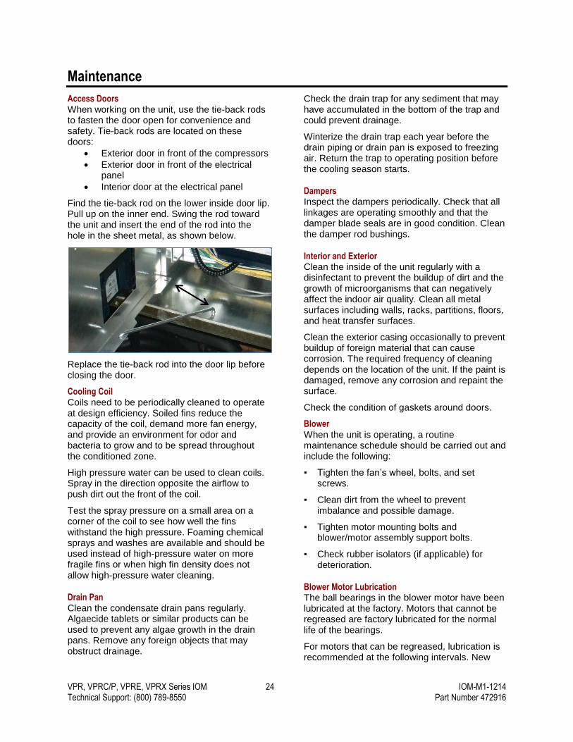
Access Doors When working on the unit, use the tie-back rods to fasten the door open for convenience and safety. Tie-back rods are located on these doors:
Exterior door in front of the compressors
Exterior door in front of the electrical panel
Interior door at the electrical panel
Find the tie-back rod on the lower inside door lip. Pull up on the inner end. Swing the rod toward the unit and insert the end of the rod into the hole in the sheet metal, as shown below.
Replace the tie-back rod into the door lip before closing the door.
Cooling Coil Coils need to be periodically cleaned to operate at design efficiency. Soiled fins reduce the capacity of the coil, demand more fan energy, and provide an environment for odor and bacteria to grow and to be spread throughout the conditioned zone.
High pressure water can be used to clean coils. Spray in the direction opposite the airflow to push dirt out the front of the coil.
Test the spray pressure on a small area on a corner of the coil to see how well the fins withstand the high pressure. Foaming chemical sprays and washes are available and should be used instead of high-pressure water on more fragile fins or when high fin density does not allow high-pressure water cleaning.
Drain Pan Clean the condensate drain pans regularly. Algaecide tablets or similar products can be used to prevent any algae growth in the drain pans. Remove any foreign objects that may obstruct drainage.
Check the drain trap for any sediment that may have accumulated in the bottom of the trap and could prevent drainage.
Winterize the drain trap each year before the drain piping or drain pan is exposed to freezing air. Return the trap to operating position before the cooling season starts.
Dampers Inspect the dampers periodically. Check that all linkages are operating smoothly and that the damper blade seals are in good condition. Clean the damper rod bushings.
Interior and Exterior Clean the inside of the unit regularly with a disinfectant to prevent the buildup of dirt and the growth of microorganisms that can negatively affect the indoor air quality. Clean all metal surfaces including walls, racks, partitions, floors, and heat transfer surfaces.
Clean the exterior casing occasionally to prevent buildup of foreign material that can cause corrosion. The required frequency of cleaning depends on the location of the unit. If the paint is damaged, remove any corrosion and repaint the surface.
Check the condition of gaskets around doors.
Blower When the unit is operating, a routine maintenance schedule should be carried out and include the following:
▪ Tighten the fan’s wheel, bolts, and set screws.
▪ Clean dirt from the wheel to prevent imbalance and possible damage.
▪ Tighten motor mounting bolts and blower/motor assembly support bolts.
▪ Check rubber isolators (if applicable) for deterioration.
Blower Motor Lubrication The ball bearings in the blower motor have been lubricated at the factory. Motors that cannot be regreased are factory lubricated for the normal life of the bearings.
For motors that can be regreased, lubrication is recommended at the following intervals. New
VPR, VPRC/P, VPRE, VPRX Series IOM 25 IOM-M1-1214 Technical Support: (800) 789-8550 Part Number 472916
motors that have been stored for a year or more should also be relubricated.
Lubrication Intervals
Frame Size NEMA (IEC) Rated Speed (RPM)
3,600 1,800 1,200 900
Up to 210 incl. (132) 5,500 hours
12,000 hours
18,000 hours
22,000 hours
Over 210 to 280 incl. (180) 3,600 hours
9,500 hours
15,000 hours
18,000 hours
Over 280 to 360 incl. (225) 2,200 hours
7,400 hours
12,000 hours
15,000 hours
Over 360 to 5000 incl. (300) 2,200 hours
3,500 hours
7,400 hours
10,500 hours
For information about bearing lubrication and maintenance for a Baldor motor, refer to the Baldor IOM included with the Valent Cut Sheets. Baldor motors are pregreased, normally with Polyrex EM (Exxon Mobil). If other greases are preferred, check with a local Baldor Service Center for recommendations.
Motors can be regreased while stopped (at less than 176°F) or running.
1. Clean the grease fitting or area around the grease hole if equipped with slotted grease screws.
2. If the motor has a purge plug, remove it.
3. Slowly apply grease to the fitting or grease hole. Refer to the following table for the recommended amount of grease to add. Too much grease or injecting grease too quickly can cause premature bearing failure. Take a minute or more to apply the grease.
4. Operate the motor for 20 minutes, then reinstall the purge plug if it was previously removed.
IMPORTANT: Keep grease clean. Mixing dissimilar greases is not recommended.
Amount of Grease to Add
Frame Size NEMA (IEC) By Weight
ounces (grams)
By Volume
Inches3 Teaspoons
Up to 210 incl. (132) 0.30 (8.4) 0.6 2.0
Over 210 to 280 incl. (180) 0.61 (17.4) 1.2 3.9
Over 280 to 360 incl. (225) 0.81 (23.1) 1.5 5.2
Over 360 to 5000 incl. (300) 2.12 (60.0) 4.1 13.4
Furnace Consult the manufacturer’s manual for information about furnace maintenance.
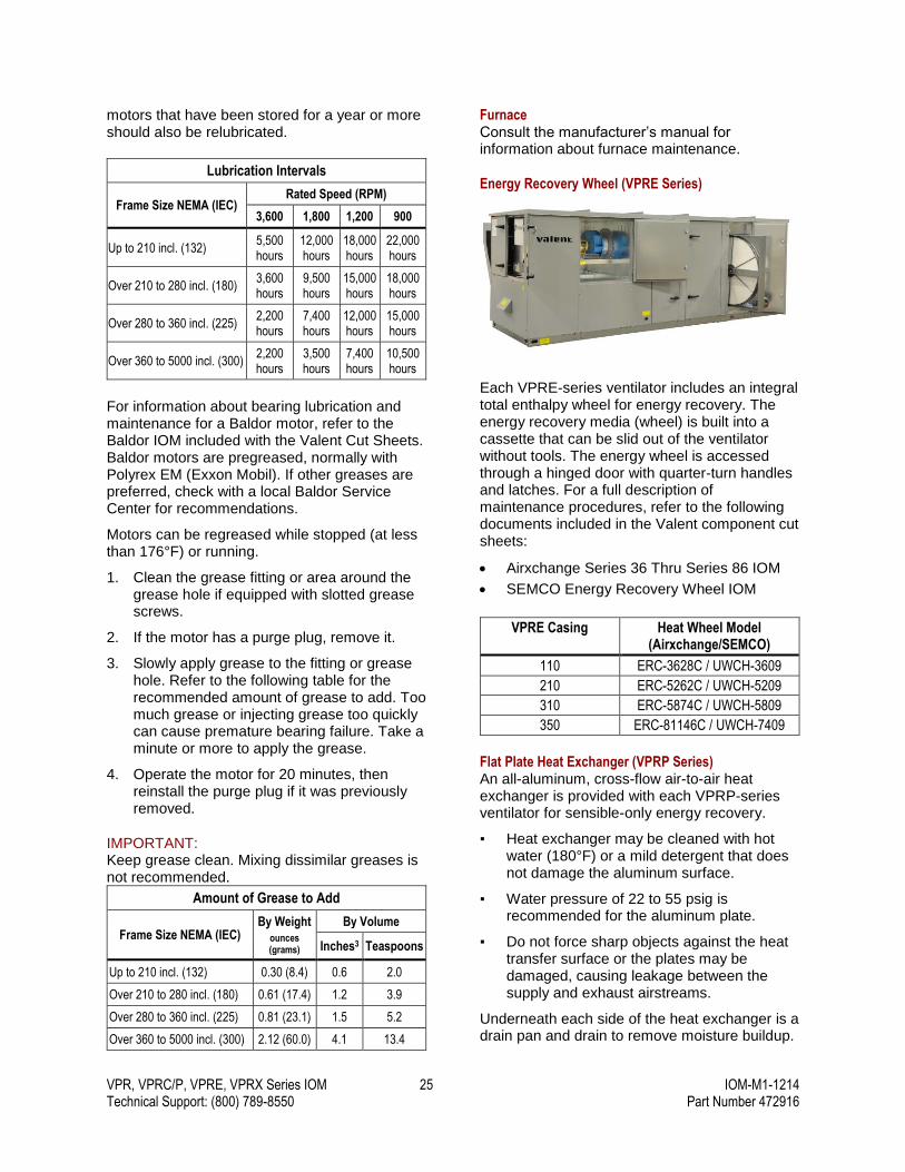
Energy Recovery Wheel (VPRE Series)
Each VPRE-series ventilator includes an integral total enthalpy wheel for energy recovery. The energy recovery media (wheel) is built into a cassette that can be slid out of the ventilator without tools. The energy wheel is accessed through a hinged door with quarter-turn handles and latches. For a full description of maintenance procedures, refer to the following documents included in the Valent component cut sheets:
Airxchange Series 36 Thru Series 86 IOM
SEMCO Energy Recovery Wheel IOM
VPRE Casing Heat Wheel Model (Airxchange/SEMCO)
110 ERC-3628C / UWCH-3609
210 ERC-5262C / UWCH-5209
310 ERC-5874C / UWCH-5809
350 ERC-81146C / UWCH-7409
Flat Plate Heat Exchanger (VPRP Series) An all-aluminum, cross-flow air-to-air heat exchanger is provided with each VPRP-series ventilator for sensible-only energy recovery.
▪ Heat exchanger may be cleaned with hot water (180°F) or a mild detergent that does not damage the aluminum surface.
▪ Water pressure of 22 to 55 psig is recommended for the aluminum plate.
▪ Do not force sharp objects against the heat transfer surface or the plates may be damaged, causing leakage between the supply and exhaust airstreams.
Underneath each side of the heat exchanger is a drain pan and drain to remove moisture buildup.
VPR, VPRC/P, VPRE, VPRX Series IOM 26 IOM-M1-1214 Technical Support: (800) 789-8550 Part Number 472916
VPRP Casing Heat Exchanger Model
110 30A-900
210 30A-1200
310 50B-1200
350 50C-1650
Enthalpy Plate (VPRC Series) An enthalpic cross-flow air-to-air heat exchanger is provided with each VPRC-series ventilator for both sensible and latent energy recovery.
Heat exchanger may be cleaned with hot water (180°F) or a mild detergent that does not damage the enthalpic surface. Refer to the manufacturer’s cleaning instructions on page 41.
To avoid damage, do not use a high-pressure water source (pressure washer) to clean the enthalpy plate.
Underneath each side of the heat exchanger is a drain pan and drain to remove moisture buildup.
VPRC with Bypass Casing
Heat Exchanger Model
110 Module B
210 Module B, Module E
310 Module C, Module F
350 Module G
Filters Change the filters regularly. Pressure drop readings can be used to determine when a filter should be replaced. Pre-filters should be replaced according to the pressure drop change-out guidelines from the filter manufacturer or as required by system design.
All filter sections can be accessed by a door. Filters can be removed by sliding them out of the rack. Some filters are secured to the frame using a clip. Aluminum filters can be removed and cleaned using high-pressure water.
Filter Media Type
Filter Media
Quantity
Outdoor Air
Exhaust Air
Supply Air
2" Aluminum X X
2" MERV 8 X X X
4" MERV 8 X
4" MERV 11 X
4" MERV 14 X
Filter Media Sizes and Quantities
Casing Quantity
Outdoor Air Exhaust Air Supply Air
110 (4) 20x20 (2) 20x20 (4) 20x20
210 (6) 16x25 (3) 16x25 (6) 16x25
310 (6) 20x24 (4) 16x25 (9) 20x24
350 (30, 40 tons) (9) 20x24 + (3) 20x20 (6) 20x24 + (2) 20x20 6-row DX coil: (6) 20x24 + (2) 20x20 4-row DX coil: (9) 20x24 + (3) 20x20
350 (50, 60 tons) (9) 20x24 + (3) 20x20 (6) 20x24 + (2) 20x20 (9) 20x24 + (3) 20x20
VPR, VPRC/P, VPRE, VPRX Series IOM 27 IOM-M1-1214 Technical Support: (800) 789-8550 Part Number 472916
Compressor Staging
Cooling Mode – The Digital Scroll compressor (Circuit B) will engage to maintain cooling demand. If more cooling is needed than the Digital Scroll compressor can provide, the Standard Scroll compressor (Circuit A) will engage and the Digital Scroll compressor (Circuit B) will modulate to maintain the desired supply air temperature.
Dehumidification Mode – For units equipped with a hot gas reheat coil, the Standard Scroll compressor (Circuit A) will run to lower the DX coil temperature to the DX coil setpoint and modulate the hot gas reheat (HGRH) valve to maintain the supply air temperature. If more capacity is needed to decrease the DX coil temperature to the setpoint, the Digital Scroll compressor (Circuit B) will engage to meet the setpoint. The hot gas reheat valve will continue to modulate as needed to maintain the supply air temperature.
Units with 4 Compressors Cooling Mode Dehumidification Mode For units equipped with a hot gas reheat coil
Circuit Circuit B; Circuit A if needed Circuit A; Circuit B if needed
Physical Compressor Labels 3 and 4; 1 and 2 if needed 1 and 2; 3 and 4 if needed
Controls Compressor Labels 1 and 2; 3 and 4 if needed 3 and 4; 1 and 2 if needed
Units with 2 Compressors Cooling Mode Dehumidification Mode For units equipped with a hot gas reheat coil
Circuit Circuit B; Circuit A if needed Circuit A; Circuit B if needed
Physical Compressor Labels 2; 1 if needed 1; 2 if needed
Controls Compressor Labels 1; 2 if needed 2; 1 if needed
Sensor Trip and Reset Values
Sensor/Cutout Trip Reset
Low Limit (Freezestat) 35°F 46°F
Furnace High Limit 194°F 164°F
Furnace Aux High Limit 160°F 120°F
Electric Heat High Limit 125°F 90°F
Low Pressure (Air Cooled) 75 ±5psig 95 ±7psig
Low Pressure (Heat Pump) 25 ±5psig 50 ±5psig
High Pressure (Refrigeration) 610 ±25psig Manual
Condenser Fan Cycling Switch 450 ±15psig 350 ±10psig
VPR, VPRC/P, VPRE, VPRX Series IOM 28 IOM-M1-1214 Technical Support: (800) 789-8550 Part Number 472916
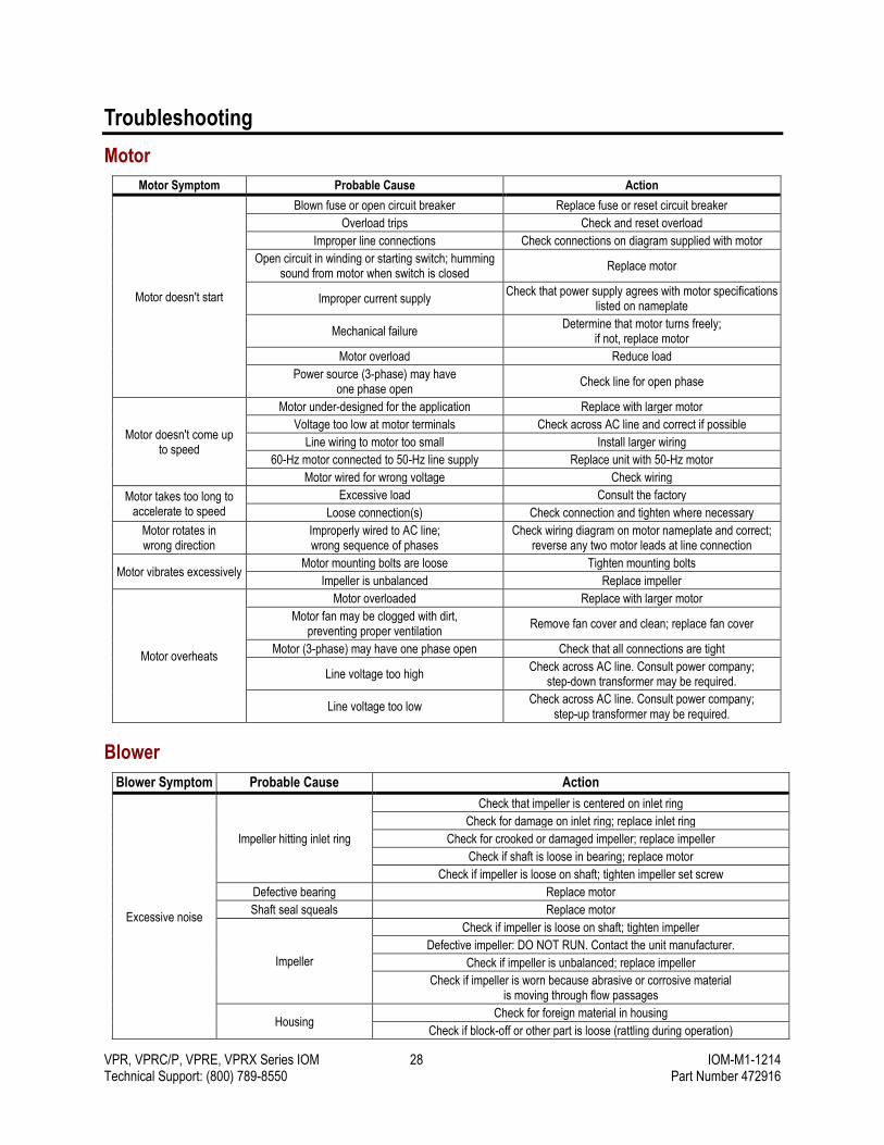
Troubleshooting
Motor
Motor Symptom Probable Cause Action
Motor doesn't start
Blown fuse or open circuit breaker Replace fuse or reset circuit breaker
Overload trips Check and reset overload
Improper line connections Check connections on diagram supplied with motor
Open circuit in winding or starting switch; humming sound from motor when switch is closed
Replace motor
Improper current supply Check that power supply agrees with motor specifications
listed on nameplate
Mechanical failure Determine that motor turns freely;
if not, replace motor
Motor overload Reduce load
Power source (3-phase) may have one phase open
Check line for open phase
Motor doesn't come up to speed
Motor under-designed for the application Replace with larger motor
Voltage too low at motor terminals Check across AC line and correct if possible
Line wiring to motor too small Install larger wiring
60-Hz motor connected to 50-Hz line supply Replace unit with 50-Hz motor
Motor wired for wrong voltage Check wiring
Motor takes too long to accelerate to speed
Excessive load Consult the factory
Loose connection(s) Check connection and tighten where necessary
Motor rotates in wrong direction
Improperly wired to AC line; wrong sequence of phases
Check wiring diagram on motor nameplate and correct; reverse any two motor leads at line connection
Motor vibrates excessively Motor mounting bolts are loose Tighten mounting bolts
Impeller is unbalanced Replace impeller
Motor overheats
Motor overloaded Replace with larger motor
Motor fan may be clogged with dirt, preventing proper ventilation
Remove fan cover and clean; replace fan cover
Motor (3-phase) may have one phase open Check that all connections are tight
Line voltage too high Check across AC line. Consult power company;
step-down transformer may be required.
Line voltage too low Check across AC line. Consult power company;
step-up transformer may be required.
Blower
Blower Symptom Probable Cause Action
Excessive noise
Impeller hitting inlet ring
Check that impeller is centered on inlet ring
Check for damage on inlet ring; replace inlet ring
Check for crooked or damaged impeller; replace impeller
Check if shaft is loose in bearing; replace motor
Check if impeller is loose on shaft; tighten impeller set screw
Defective bearing Replace motor
Shaft seal squeals Replace motor
Impeller
Check if impeller is loose on shaft; tighten impeller
Defective impeller: DO NOT RUN. Contact the unit manufacturer.
Check if impeller is unbalanced; replace impeller
Check if impeller is worn because abrasive or corrosive material is moving through flow passages
Housing Check for foreign material in housing
Check if block-off or other part is loose (rattling during operation)
VPR, VPRC/P, VPRE, VPRX Series IOM 29 IOM-M1-1214 Technical Support: (800) 789-8550 Part Number 472916
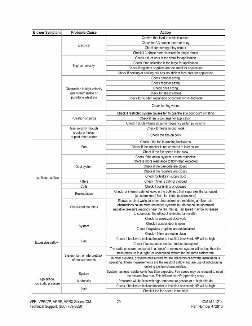
Blower Symptom Probable Cause Action
Electrical
Confirm that lead-in cable is secure
Check for AC hum in motor or relay
Check for starting relay chatter
Check if 3-phase motor is wired for single phase
High air velocity
Check if duct work is too small for application
Check if fan selection is too large for application
Check if registers or grilles are too small for application
Check if heating or cooling coil has insufficient face area for application
Obstruction in high-velocity gas stream (rattle or pure-tone whistles)
Check damper sizing
Check register sizing
Check grille sizing
Check for sharp elbows
Check for sudden expansion or contraction in ductwork
Check turning vanes
Pulsation or surge
Check if restricted system causes fan to operate at a poor point of rating
Check if fan is too large for application
Check if ducts vibrate at same frequency as fan pulsations
Gas velocity through cracks or holes,
or past obstructions
Check for leaks in duct work
Check the fins on coils
Insufficient airflow
Fan
Check if the fan is running backwards
Check if the impeller is not centered in inlet collars
Check if the fan speed is too slow
Duct system
Check if the actual system is more restrictive (there is more resistance to flow) than expected
Check if the dampers are closed
Check if the registers are closed
Check for leaks in supply duct
Filters Check if filter is dirty or clogged
Coils Check if coil is dirty or clogged
Recirculation Check for internal cabinet leaks in the bulkhead that separates the fan outlet
(pressure zone) from fan inlets (suction zone)
Obstructed fan inlets
Elbows, cabinet walls, or other obstructions are restricting air flow. Inlet obstructions cause more restrictive systems but do not cause increased
negative pressure readings near the fan inlet(s). Fan speed may be increased to counteract the effect of restricted fan inlet(s).
Excessive airflow
System
Check for oversized duct work
Check if access door is open
Check if registers or grilles are not installed
Check if filters are not in place
Fan Check if backward-inclined impeller is installed backward; HP will be high
Check if fan speed is too fast; reduce fan speed
System, fan, or interpretation of measurements
The static pressure measured in a “loose” or oversized system will be less than the static pressure in a “tight” or undersized system for the same airflow rate.
In most systems, pressure measurements are indicators of how the installation is operating. These measurements are the result of airflow and are useful indicators in
defining system characteristics.
High airflow, low static pressure
System System has less resistance to flow than expected. Fan speed may be reduced to obtain
the desired flow rate. This will reduce HP (operating cost).
Air density Pressures will be less with high-temperature gasses or at high altitude
Fan Check if backward-inclined impeller is installed backward; HP will be high
Check if the fan speed is too high
VPR, VPRC/P, VPRE, VPRX Series IOM 30 IOM-M1-1214 Technical Support: (800) 789-8550 Part Number 472916
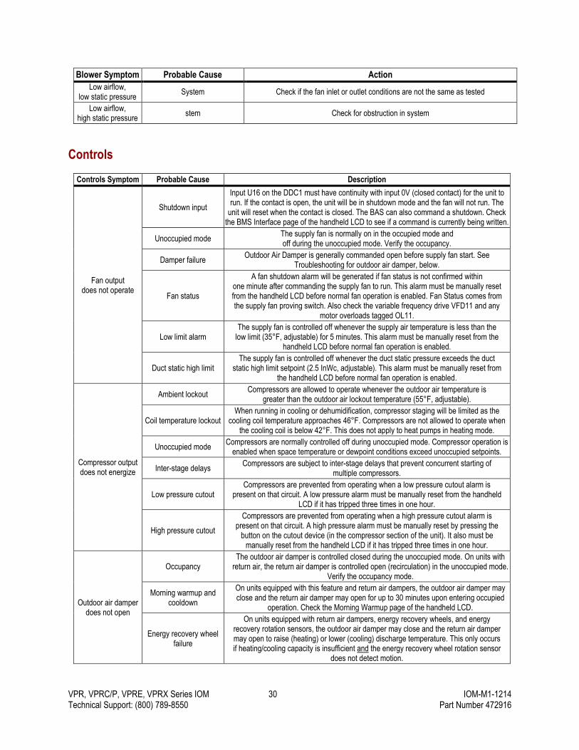
Blower Symptom Probable Cause Action
Low airflow, low static pressure
System Check if the fan inlet or outlet conditions are not the same as tested
Low airflow, high static pressure
stem Check for obstruction in system
Controls
Controls Symptom Probable Cause Description
Fan output does not operate
Shutdown input
Input U16 on the DDC1 must have continuity with input 0V (closed contact) for the unit to run. If the contact is open, the unit will be in shutdown mode and the fan will not run. The
unit will reset when the contact is closed. The BAS can also command a shutdown. Check the BMS Interface page of the handheld LCD to see if a command is currently being written.
Unoccupied mode The supply fan is normally on in the occupied mode and off during the unoccupied mode. Verify the occupancy.
Damper failure Outdoor Air Damper is generally commanded open before supply fan start. See
Troubleshooting for outdoor air damper, below.
Fan status
A fan shutdown alarm will be generated if fan status is not confirmed within one minute after commanding the supply fan to run. This alarm must be manually reset from the handheld LCD before normal fan operation is enabled. Fan Status comes from the supply fan proving switch. Also check the variable frequency drive VFD11 and any
motor overloads tagged OL11.
Low limit alarm The supply fan is controlled off whenever the supply air temperature is less than the
low limit (35°F, adjustable) for 5 minutes. This alarm must be manually reset from the handheld LCD before normal fan operation is enabled.
Duct static high limit The supply fan is controlled off whenever the duct static pressure exceeds the duct
static high limit setpoint (2.5 InWc, adjustable). This alarm must be manually reset from the handheld LCD before normal fan operation is enabled.
Compressor output does not energize
Ambient lockout Compressors are allowed to operate whenever the outdoor air temperature is
greater than the outdoor air lockout temperature (55°F, adjustable).
Coil temperature lockout When running in cooling or dehumidification, compressor staging will be limited as the
cooling coil temperature approaches 46°F. Compressors are not allowed to operate when the cooling coil is below 42°F. This does not apply to heat pumps in heating mode.
Unoccupied mode Compressors are normally controlled off during unoccupied mode. Compressor operation is
enabled when space temperature or dewpoint conditions exceed unoccupied setpoints.
Inter-stage delays Compressors are subject to inter-stage delays that prevent concurrent starting of
multiple compressors.
Low pressure cutout Compressors are prevented from operating when a low pressure cutout alarm is
present on that circuit. A low pressure alarm must be manually reset from the handheld LCD if it has tripped three times in one hour.
High pressure cutout
Compressors are prevented from operating when a high pressure cutout alarm is present on that circuit. A high pressure alarm must be manually reset by pressing the
button on the cutout device (in the compressor section of the unit). It also must be manually reset from the handheld LCD if it has tripped three times in one hour.
Outdoor air damper does not open
Occupancy The outdoor air damper is controlled closed during the unoccupied mode. On units with
return air, the return air damper is controlled open (recirculation) in the unoccupied mode. Verify the occupancy mode.
Morning warmup and cooldown
On units equipped with this feature and return air dampers, the outdoor air damper may close and the return air damper may open for up to 30 minutes upon entering occupied
operation. Check the Morning Warmup page of the handheld LCD.
Energy recovery wheel failure
On units equipped with return air dampers, energy recovery wheels, and energy recovery rotation sensors, the outdoor air damper may close and the return air damper may open to raise (heating) or lower (cooling) discharge temperature. This only occurs if heating/cooling capacity is insufficient and the energy recovery wheel rotation sensor
does not detect motion.
VPR, VPRC/P, VPRE, VPRX Series IOM 31 IOM-M1-1214 Technical Support: (800) 789-8550 Part Number 472916
Controls Symptom Probable Cause Description
End switch failure
When the outdoor air damper is commanded open, the controller waits for the end switch of the damper actuator(s) to confirm that there is an airflow path. If, after 2
minutes, end switch closure is not confirmed, a damper switch (end switch) alarm is generated. It must be manually reset from the handheld LCD. Check the damper actuators are properly configured. Set Mode dial = 3. If actuator is equipped, set
outdoor air damper AUC dial = 0.25 and return air damper AUX = 0.75.
Dehumidification not enabled
Space relative humidity sensor/value
Occupied dehumidification is enabled when the space relative humidity or outdoor dewpoint temperature is greater than setpoint. If the space relative humidity sensor is not connected or operating properly, dehumidification will be determined by the
outdoor air dewpoint. The space relative humidity reading may be sent by the BAS.
Outdoor air dewpoint setpoint
Occupied dehumidification is enabled when the space relative humidity or outdoor dewpoint temperature is greater than setpoint. The outdoor dewpoint is calculated from the outdoor
air temperature and relative humidity. If either the outdoor air temperature or relative humidity sensor is not connected or operating properly, dehumidification may not operate.
The outdoor air temperature and relative humidity may be sent by the BAS.
Space dewpoint dehumidification cutout
Dehumidification of the space is disabled when the space dewpoint falls below this threshold. Check the space temperature and relative humidity sensors for proper
operation. Space temperature and relative humidity reading may be sent by the BAS.
Unoccupied space dewpoint setpoint
Unoccupied dehumidification is enabled when the space humidity is greater than setpoint. Check the space relative humidity sensors. The space relative humidity
reading may be sent by the BAS.
Gas furnace does not operate
Electric heat inter-stage delay
For units with both gas and electric heat (Temperator option), the electric heat is the first stage of heat, followed by gas heat. For gas heat operation to be enabled, the electric heat
must be at 100% capacity for five minutes.
High limit output Both gas and electric heaters are equipped with high temperature limit switches, both
manual and automatic reset. Check schematics for locations and operation type.
Occupied/unoccupied control not
operating properly
The occupancy mode of the controller is determined by three sources: hardwired occupancy input, local (internal schedule), or network (BAS) schedule/command.
Local (internal) schedule Unit default is 24/7 occupied by internal schedule, which is edited using the Schedule menu
of the handheld LCD. Be sure to set the controller time and date.
Hardwired occupancy input
To allow hardwired input to determine occupancy set local schedule to 24/7 unoccupied. Input U15 on the DDC1 must have continuity with input 0V closed contact) for occupied
operation. When input U15 is open, the unit is unoccupied.
Controller time and date The local time and date must be set for the local schedule to correctly determine the occupancy mode. These values are stored in the controller for several months with
battery backup. Use the System Settings menu of the handheld LCD.
Network (BAS) schedule/command
The two occupancy points are BAS occupancy enable and BAS occupancy command. When BAS control of occupancy is enabled, the BAS occupancy command point
determines occupancy. Check the BMS Interface page of the handheld LCD to see the status of these points.
Compressor does not cycle off
Coil temperature setpoint not satisfied
In the dehumidification mode the compressors cycle to maintain the evaporator coil temperature setpoint (53°F, typical). At least one compressor will remain on while
dehumidification is active.
Supply air temperature setpoint not satisfied
During the normal control sequence (dehumidification not enabled) the compressors cycle to maintain the supply air temperature setpoint. The compressor(s) will remain on
until the supply air setpoint is satisfied.
VPR, VPRC/P, VPRE, VPRX Series IOM 32 IOM-M1-1214 Technical Support: (800) 789-8550 Part Number 472916
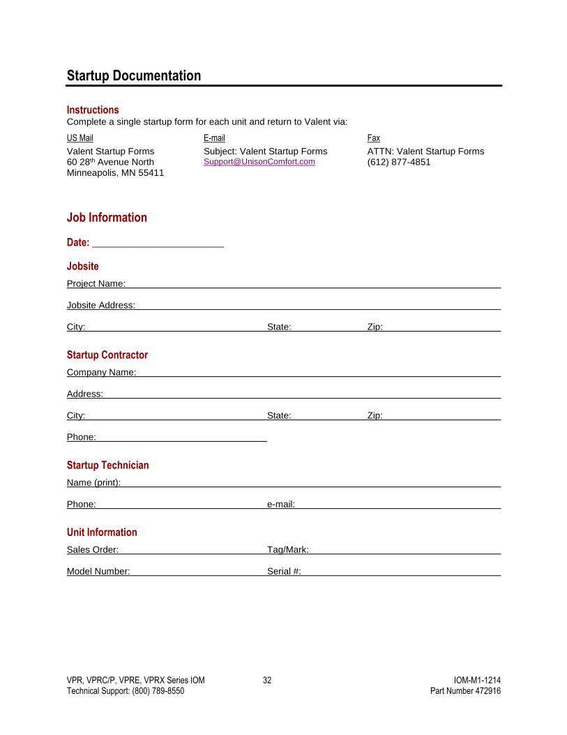
Startup Documentation
Instructions Complete a single startup form for each unit and return to Valent via:
US Mail
Valent Startup Forms 60 28th Avenue North Minneapolis, MN 55411
Subject: Valent Startup Forms [email protected]
Fax
ATTN: Valent Startup Forms (612) 877-4851
Job Information
Date: __________________________
Jobsite
Project Name:
Jobsite Address:
City: State: Zip:
Startup Contractor
Company Name:
Address:
City: State: Zip:
Phone:
Startup Technician
Name (print):
Phone: e-mail:
Unit Information
Sales Order: Tag/Mark:
Model Number: Serial #:

VPR, VPRC/P, VPRE, VPRX Series IOM 33 IOM-M1-1214 Technical Support: (800) 789-8550 Part Number 472916
Startup Checklist
Standard Unit Features The following items should be checked on all Valent units prior to startup.
Exterior and Interior Inspection
Unit is inspected for rigging or shipping damage.
Report any damage to the manufacturer.
Unit is installed correctly, is level, and all doors are operable.
Unit is secured to curb or mounting supports.
Doors operate smoothly and gaskets are in place.
All shipping blocks, tie downs, and bolts are removed.
Condensate drain is piped and trapped.
Condensate drains are primed.
External ductwork is completed and correctly installed.
Outdoor air intake hood is installed, bird screen is in place, and opening is unobstructed.
Interior of unit is free of debris.
Copper tubing is secured and not rubbing.
Filters are installed correctly.
Controls and Electrical
The main disconnect is off.
All field-mounted sensors and instruments are installed and wired.
Unit controls are off.
Electrical service matches unit voltage.
Electrical field wiring is complete.
All electrical connections are tightened.
Compressor and motor breakers or fuses are open (disabled).
Main power is wired to the disconnect.
Discharge air sensor is installed per the Wiring instructions in this IOM.
Space temperature and humidity sensors are installed per the Wiring instructions in this IOM.
Hot Water / Chilled Water Coils
Chilled water piping system is complete.
Hot water piping system is complete.
Control valves are installed, wired, and operating properly.
Water coils are balanced to design gpm.
Water system is free of air.
Fans and Motors
Fan inlets and outlets are unobstructed.
Fasteners, setscrews, and locking collars on the fan are secure.
Fasteners on the motor and base are secure.
Fan wheel rotates freely by hand and no parts are rubbing.
Electrical connections are properly secured.
Housing and ductwork, if accessible, are cleared of obstructions and foreign material that may damage the fan wheel.
Optional Unit Features The following items should be checked as they apply to the specific unit being started up.
Compressors
Compressor shipping brackets are removed.
Crankcase heaters must be energized for a minimum of 12 hours before startup.
IG Furnace
Gas piping is complete and gas lines are purged.
Gas venting is in place.
Water Source Heat Pump
All water/fluid connections are piped with field-supplied strainer, shutoff valves, and pressure/temperature ports.
Water/fluid loop is filled with required glycol/water mix.
Water/fluid loop pumps and VFDs are operational, enabled, and ready to supply fluid to unit such that opening the unit shutoff valves will result in flow at the required gpm.
Water/fluid flow to each circuit has been measured and matches unit design (3 gpm/ton).
Water/fluid entering water temperature has been measured and matches design.
Strainers checked for blockage and cleaned if necessary.
VPR, VPRC/P, VPRE, VPRX Series IOM 34 IOM-M1-1214 Technical Support: (800) 789-8550 Part Number 472916
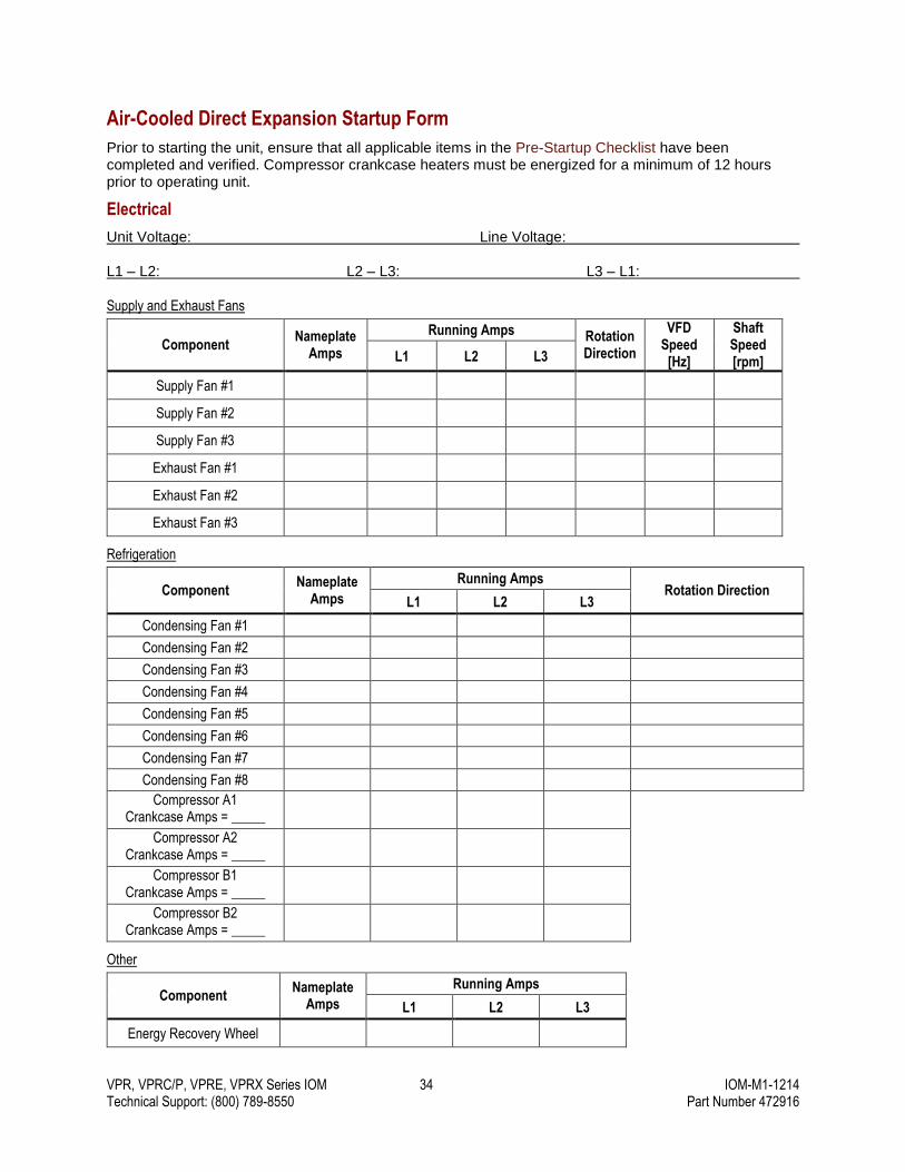
Air-Cooled Direct Expansion Startup Form
Prior to starting the unit, ensure that all applicable items in the Pre-Startup Checklist have been completed and verified. Compressor crankcase heaters must be energized for a minimum of 12 hours prior to operating unit.
Electrical
Unit Voltage: Line Voltage:
L1 – L2: L2 – L3: L3 – L1:
Supply and Exhaust Fans
Component Nameplate
Amps
Running Amps Rotation Direction
VFD Speed
[Hz]
Shaft Speed [rpm] L1 L2 L3
Supply Fan #1
Supply Fan #2
Supply Fan #3
Exhaust Fan #1
Exhaust Fan #2
Exhaust Fan #3
Refrigeration
Component Nameplate
Amps
Running Amps Rotation Direction
L1 L2 L3
Condensing Fan #1
Condensing Fan #2
Condensing Fan #3
Condensing Fan #4
Condensing Fan #5
Condensing Fan #6
Condensing Fan #7
Condensing Fan #8
Compressor A1 Crankcase Amps = _____
Compressor A2 Crankcase Amps = _____
Compressor B1 Crankcase Amps = _____
Compressor B2 Crankcase Amps = _____
Other
Component Nameplate
Amps
Running Amps
L1 L2 L3
Energy Recovery Wheel
VPR, VPRC/P, VPRE, VPRX Series IOM 35 IOM-M1-1214 Technical Support: (800) 789-8550 Part Number 472916
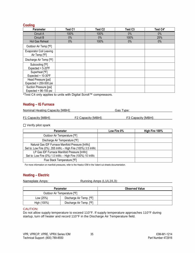
Cooling Parameter Test C1 Test C2 Test C3 Test C4*
Circuit A 100% 100% 0% 0%
Circuit B 0% 0% 100% 25%
Hot Gas Reheat 0% 100% 0% 0%
Outdoor Air Temp [ºF]
Evaporator Coil Leaving Air Temp [ºF]
Discharge Air Temp [ºF]
Subcooling [ºF] Expected = 5-20ºF
Superheat [ºF] Expected = 10-30ºF
Head Pressure [psi] Expected = 250-500 psi
Suction Pressure [psi] Expected = 96-155 psi
*Test C4 only applies to units with Digital Scroll™ compressors.
Heating – IG Furnace
Nominal Heating Capacity [MBH]: Gas Type:
F1 Capacity [MBH]: F2 Capacity [MBH]: F3 Capacity [MBH]:
Verify pilot spark
Parameter Low Fire 0% High Fire 100%
Outdoor Air Temperature [ºF]
Discharge Air Temperature [ºF]
Natural Gas IDF Furnace Manifold Pressure [InWc] Set to: Low Fire (0%) .355 InWc – High Fire (100%) 3.5 InWc
LP Gas IDF Furnace Manifold Pressure [InWc] Set to: Low Fire (0%) 1.0 InWc – High Fire (100%) 10 InWc
Flue Stack Temperature [ºF]
For more information on manifold pressures, refer to the Heatco IOM in the Valent cut sheets documentation.
Heating – Electric
Nameplate Amps: Running Amps (L1/L2/L3):
Parameter Observed Value
Outdoor Air Temperature [ºF]
Low (25%) Discharge Air Temp. [ºF]
High (100%) Discharge Air Temp. [ºF]
CAUTION: Do not allow supply temperature to exceed 110°F. If supply temperature approaches 110°F during startup, turn off heater and record 110°F in the Discharge Air Temperature field.
VPR, VPRC/P, VPRE, VPRX Series IOM 36 IOM-M1-1214 Technical Support: (800) 789-8550 Part Number 472916
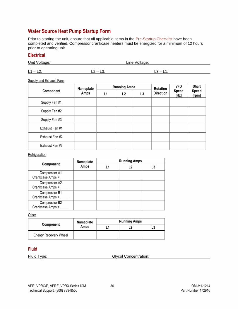
Water Source Heat Pump Startup Form
Prior to starting the unit, ensure that all applicable items in the Pre-Startup Checklist have been completed and verified. Compressor crankcase heaters must be energized for a minimum of 12 hours prior to operating unit.
Electrical
Unit Voltage: Line Voltage:
L1 – L2: L2 – L3: L3 – L1:
Supply and Exhaust Fans
Component Nameplate
Amps
Running Amps Rotation Direction
VFD Speed
[Hz]
Shaft Speed [rpm] L1 L2 L3
Supply Fan #1
Supply Fan #2
Supply Fan #3
Exhaust Fan #1
Exhaust Fan #2
Exhaust Fan #3
Refrigeration
Component Nameplate
Amps
Running Amps
L1 L2 L3
Compressor A1 Crankcase Amps = _____
Compressor A2 Crankcase Amps = _____
Compressor B1 Crankcase Amps = _____
Compressor B2 Crankcase Amps = _____
Other
Component Nameplate
Amps
Running Amps
L1 L2 L3
Energy Recovery Wheel
Fluid
Fluid Type: Glycol Concentration:
VPR, VPRC/P, VPRE, VPRX Series IOM 37 IOM-M1-1214 Technical Support: (800) 789-8550 Part Number 472916
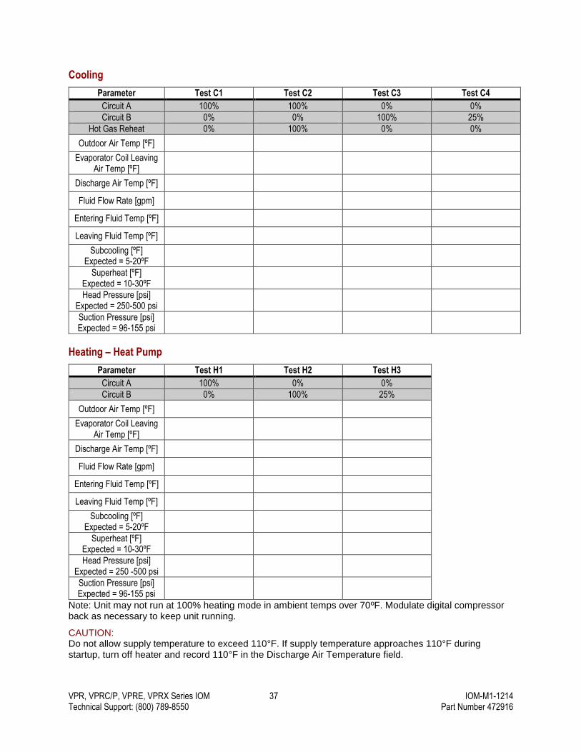
Cooling
Parameter Test C1 Test C2 Test C3 Test C4
Circuit A 100% 100% 0% 0%
Circuit B 0% 0% 100% 25%
Hot Gas Reheat 0% 100% 0% 0%
Outdoor Air Temp [ºF]
Evaporator Coil Leaving Air Temp [ºF]
Discharge Air Temp [ºF]
Fluid Flow Rate [gpm]
Entering Fluid Temp [ºF]
Leaving Fluid Temp [ºF]
Subcooling [ºF] Expected = 5-20ºF
Superheat [ºF] Expected = 10-30ºF
Head Pressure [psi] Expected = 250-500 psi
Suction Pressure [psi] Expected = 96-155 psi
Heating – Heat Pump
Parameter Test H1 Test H2 Test H3
Circuit A 100% 0% 0%
Circuit B 0% 100% 25%
Outdoor Air Temp [ºF]
Evaporator Coil Leaving Air Temp [ºF]
Discharge Air Temp [ºF]
Fluid Flow Rate [gpm]
Entering Fluid Temp [ºF]
Leaving Fluid Temp [ºF]
Subcooling [ºF] Expected = 5-20ºF
Superheat [ºF] Expected = 10-30ºF
Head Pressure [psi] Expected = 250 -500 psi
Suction Pressure [psi] Expected = 96-155 psi
Note: Unit may not run at 100% heating mode in ambient temps over 70ºF. Modulate digital compressor back as necessary to keep unit running.
CAUTION: Do not allow supply temperature to exceed 110°F. If supply temperature approaches 110°F during startup, turn off heater and record 110°F in the Discharge Air Temperature field.
VPR, VPRC/P, VPRE, VPRX Series IOM 38 IOM-M1-1214 Technical Support: (800) 789-8550 Part Number 472916
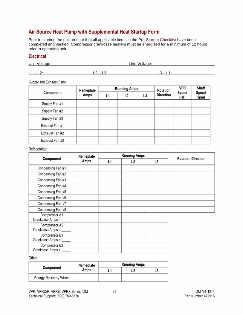
Air Source Heat Pump with Supplemental Heat Startup Form
Prior to starting the unit, ensure that all applicable items in the Pre-Startup Checklist have been completed and verified. Compressor crankcase heaters must be energized for a minimum of 12 hours prior to operating unit.
Electrical
Unit Voltage: Line Voltage:
L1 – L2: L2 – L3: L3 – L1:
Supply and Exhaust Fans
Component Nameplate
Amps
Running Amps Rotation Direction
VFD Speed
[Hz]
Shaft Speed [rpm] L1 L2 L3
Supply Fan #1
Supply Fan #2
Supply Fan #3
Exhaust Fan #1
Exhaust Fan #2
Exhaust Fan #3
Refrigeration
Component Nameplate
Amps
Running Amps Rotation Direction
L1 L2 L3
Condensing Fan #1
Condensing Fan #2
Condensing Fan #3
Condensing Fan #4
Condensing Fan #5
Condensing Fan #6
Condensing Fan #7
Condensing Fan #8
Compressor A1 Crankcase Amps = _____
Compressor A2 Crankcase Amps = _____
Compressor B1 Crankcase Amps = _____
Compressor B2 Crankcase Amps = _____
Other
Component Nameplate
Amps
Running Amps
L1 L2 L3
Energy Recovery Wheel

VPR, VPRC/P, VPRE, VPRX Series IOM 39 IOM-M1-1214 Technical Support: (800) 789-8550 Part Number 472916
Cooling
Parameter Test C1 Test C2 Test C3 Test C4
Circuit A 100% 100% 0% 0%
Circuit B 0% 0% 100% 25%
Hot Gas Reheat 0% 100% 0% 0%
Outdoor Air Temp [ºF]
Evaporator Coil Leaving Air Temp [ºF]
Discharge Air Temp [ºF]
Subcooling [ºF] Expected = 5-20ºF
Superheat [ºF] Expected = 10-30ºF
Head Pressure [psi] Expected = 250-500 psi
Suction Pressure [psi] Expected = 96-155 psi
Heating – Heat Pump
Parameter Test H1 Test H2 Test H3
Circuit A 100% 0% 0%
Circuit B 0% 100% 25%
Outdoor Air Temp [ºF]
Evaporator Coil Leaving Air Temp [ºF]
Discharge Air Temp [ºF]
Subcooling [ºF] Expected = 5-20ºF
Superheat [ºF] Expected = 10-30ºF
Head Pressure [psi] Expected = 250-500 psi
Suction Pressure [psi] Expected = 96-155 psi
VPR, VPRC/P, VPRE, VPRX Series IOM 40 IOM-M1-1214 Technical Support: (800) 789-8550 Part Number 472916
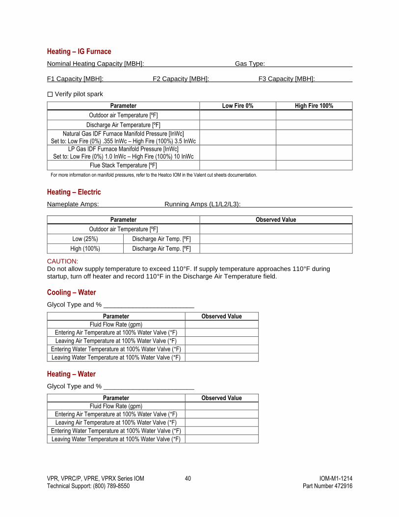
Heating – IG Furnace
Nominal Heating Capacity [MBH]: Gas Type:
F1 Capacity [MBH]: F2 Capacity [MBH]: F3 Capacity [MBH]:
Verify pilot spark
Parameter Low Fire 0% High Fire 100%
Outdoor air Temperature [ºF]
Discharge Air Temperature [ºF]
Natural Gas IDF Furnace Manifold Pressure [InWc] Set to: Low Fire (0%) .355 InWc – High Fire (100%) 3.5 InWc
LP Gas IDF Furnace Manifold Pressure [InWc] Set to: Low Fire (0%) 1.0 InWc – High Fire (100%) 10 InWc
Flue Stack Temperature [ºF]
For more information on manifold pressures, refer to the Heatco IOM in the Valent cut sheets documentation.
Heating – Electric
Nameplate Amps: Running Amps (L1/L2/L3):
Parameter Observed Value
Outdoor air Temperature [ºF]
Low (25%) Discharge Air Temp. [ºF]
High (100%) Discharge Air Temp. [ºF]
CAUTION: Do not allow supply temperature to exceed 110°F. If supply temperature approaches 110°F during startup, turn off heater and record 110°F in the Discharge Air Temperature field.
Cooling – Water
Glycol Type and % _________________________
Parameter Observed Value
Fluid Flow Rate (gpm)
Entering Air Temperature at 100% Water Valve (°F)
Leaving Air Temperature at 100% Water Valve (°F)
Entering Water Temperature at 100% Water Valve (°F)
Leaving Water Temperature at 100% Water Valve (°F)
Heating – Water
Glycol Type and % _________________________
Parameter Observed Value
Fluid Flow Rate (gpm)
Entering Air Temperature at 100% Water Valve (°F)
Leaving Air Temperature at 100% Water Valve (°F)
Entering Water Temperature at 100% Water Valve (°F)
Leaving Water Temperature at 100% Water Valve (°F)
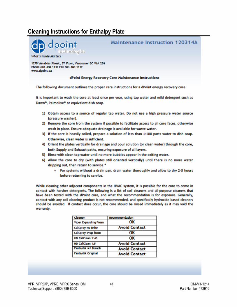
VPR, VPRC/P, VPRE, VPRX Series IOM 41 IOM-M1-1214 Technical Support: (800) 789-8550 Part Number 472916
Cleaning Instructions for Enthalpy Plate

VPR, VPRC/P, VPRE, VPRX Series IOM 42 IOM-M1-1214 Technical Support: (800) 789-8550 Part Number 472916
Warranty
UNISON COMFORT TECHNOLOGIES
LIMITED WARRANTY & DISCLAIMER POLICY (Please read the Unison Comfort Technologies terms and conditions
of sale Section 9 for additional details, conditions and exclusions.)
PRODUCT WARRANTY
Unison warrants that at the time of delivery and for a period of twelve (12) months from the initial startup or eighteen (18) months from the date of shipment, whichever is less, its products will be free from defects in materials and manufacture, provided that the products have been installed properly, maintained and operated under normal conditions and serviced in accordance with Unison’s instructions, and are operating within capacities and ratings set forth in design specifications. Labor or consumable parts are not included in this limited standard product warranty. Consumable parts include, but are not limited to, refrigerant, belts and filters.
START-UP LABOR LIMITED WARRANTY
While labor is not included in the Unison standard product warranty, Unison offers a limited labor warranty, for a period beginning on the start-up date and continuing for sixty (60) days, with the completion and documentation of a qualified start-up. The limited labor warranty will not be available if the product warranty has expired.
Start-up services are included on all Innovent compressorized products, and may be available as an option on other Unison products. These services must be performed by a Unison Certified Technician. Startup services include verifying proper operation of the unit, including proper refrigerant charge and repair of minor refrigerant leaks outside the coil. At the completion of start-up, an approved start-up record must be submitted to the Unison service department for processing. Once the start-up record is received, the (60) day limited labor warranty, from date of start-up, will be activated. Labor associated with the diagnosis, validation and repair of warranty parts failures will be covered outside of the start-up, at a negotiated labor rate.
CONSIDERATIONS REGARDING PARTS-SUPPLIED-BY-OTHERS
Unison may supply equipment at a customer’s request which has components, like controls, sensors, drives, which are engineered, provided, programmed or configured by other non-Unison parties. Unison does not provide a warranty for these parts or components. These components can be mounted in the factory or at the jobsite. In these instances, Unison’s support is limited to verification of basic functionality of the components and not the overall operation or integration of the equipment within the overall building HVAC system. As stated in the Unison Terms & Conditions – No warranty herein extended shall apply to repair or correction of conditions arising from improper or incorrectly connected air duct, piping, wiring, power supply, blown fuses, freezing, improper Product control when programmed by non-Seller controls, or personnel, or by anyone other than Seller employee or its representative. In these situations, Unison will assist in the diagnosis of issues and provide support to the customer provided the customer issues a purchase order to cover Unison’s expenses in doing so.
VPR, VPRC/P, VPRE, VPRX Series IOM 43 IOM-M1-1214 Technical Support: (800) 789-8550 Part Number 472916
Index
Air source heat pump Setup ............................................................ 21 Startup forms ................................................ 38
Blower troubleshooting ..................................... 28 Clearances ......................................................... 6 Connections
Condensate drain ......................................... 11 Curb ................................................................ 7 Duct .............................................................. 12 Gas ............................................................... 15 Indoor unit ..................................................... 17
Controls troubleshooting .................................. 30 Cooling coil maintenance ................................. 24 Curb
Dimensions ..................................................... 8 Duct connections ............................................ 7 Installation....................................................... 7
Duct connections To curb............................................................ 7 To unit ........................................................... 12
Ductwork dimensions ......................................... 8 Electrical connections ...................................... 15 Filter maintenance ............................................ 26 Freeze protection ....................................... 18, 20 Gas connections .............................................. 15
Installation Curb ................................................................ 7 Pad ................................................................. 7
Lifting instructions .............................................. 4 Model numbers .................................................. 3 Motor troubleshooting ...................................... 28 Outdoor air hood .............................................. 11 Pad installation ................................................... 7 Piping ............................................................... 20 Pressure testing ............................................... 18 Safety ................................................................. 4 Sensor wiring ................................................... 22 Startup forms
Air source heat pump equipment ................. 38 Air-cooled equipment ................................... 34 Checklist ....................................................... 33 Job information ............................................. 32 Water source heat pump equipment ............ 36
Troubleshooting Blower .......................................................... 28 Controls ........................................................ 30 Motor ............................................................ 28
Warranty .......................................................... 42 Water source heat pump
Setup ............................................................ 19 Startup forms ................................................ 36
Wiring ............................................................... 22

©December 2014 Valent® Air Management Systems
Valent® is a business of Unison™ Comfort Technologies
For service inquiries, please contact: Unison™ Comfort Technologies Technical Service (800)789-8550 [email protected]
Recommended