Mechanisms of Formation Damage
Solids Plugging
Fig 1 Illite
Clay Swelling Formation damage that occurs when water-based filtrates from drilling completion workover
or stimulation fluids enter the formation altering the ionic environment of clays via ion exchanges changes in
pH andor changes in salinity thus leading to a reduction in porosity and permeability Figures 1A-1E show
SEM photographs of several different clays
Figure 2 Smectite
Fig 3 Kaolinite
Fig 4 Chlorite
Fig 5 Smectite-Illite
Smectite for example possesses negative charges on the faces of the clay crystal while the edges are positively
charged The density of negative charges on the clay structure is determined in terms of the cation exchange
capacity (CEC) which is the amount of positively charged ions (cations) that the clay structure can
accommodate on its negatively charged exterior Thus CEC values are a measure of the clays propensity to
swell under aqueous conditions Table 1 CEC ranges of several clays
Clay Type CEC Range (Meq100g)
Smectite 80 - 150
Kaolinite 3 - 15
Illite 10 - 40
Chlorite 10 - 40
Table 1 Cation Exchange Capacity Ranges of Several Clays1
A common laboratory method for measuring CEC is through multiple salinity tests a technique used for the
determination of the electrical properties of shale containing core samples In this test the sample is flushed
with brines of different salinities and the conductivity determined after each flush A plot of the conductivity of
the sample versus the conductivity of the brine gives the excess conductivity caused by clays and other surface
conductors Then using a suitable model (eg Waxman-Smits dual water SGS) it is possible to determine the
intrinsic formation factor and porosity exponent and the cation-exchange capacity2 Another source of clay
disturbance is usually associated with changes to the wetting phase (often native formation water) In the case of
smectite and mixed-layer clays (primarily smectite-illite) a change in size due to swelling or water retention
enhances their probability of getting dislodged and migrate with the mobile wetting phase This phenomenon is
referred to as swelling-induced clay migration3
Fines Migration Formation damage which arises when the drawdown forces during flowback or production
exceed the cohesive forces between fines and the rock fabric This in turn causes particles suspended in the
produced fluid to bridge the pore throats near the wellbore reducing well productivity Fines can include
different materials such as clays (phyllosilicates smaller than 4 microns) and silts (silicates or aluminosilicates
with sizes ranging from 4 to 64 microns)4 Fines migration can be exacerbated by the use of incompatible fluid
treatments Commercial products have been developed to minimize the potential for fines migration (eg resin
consolidation tackifiers and covalent bonding of polymers)
Ultra-thin tackifying agents (UTTA) like Halliburtons SandTrapreg have been developed to stabilize fines in
high-rate producing or injection wells These systems can be applied during initial fracturing or gravel-packing
operations as a remedial treatment or as a follow up to fracturing or acidizing treatments Schlumbergers K300
is an example of technology based on the polymerization of resin All of the developed products address the
issue of fines migration and have similar solutions They all involve the application of some form of coating to
adhere fines to the mineral surfaces Advantages of resin consolidation are that it is suitable for through-tubing
applications applicable in small diameter casing and that it can be applied in abnormal pressure well5
Problems arise because resin consolidation involves multistage processes in which several fluids must be
uniformly applied sequentially into a perforated interval and frequently are highly toxic and relatively
expensive Moreover resin consolidation can significantly reduce the permeability to oil by changing the
wettability of the rock and by occluding the pore space with resin
Sand Production Formation damage that results from the production of sand and its subsequent movement
into pore throats and frasl or proppant-packs causing plugging and productivity impairment Key factors
influencing sand production are
Degree of formation consolidation which depends on cementation of sand grains around the perforation
tunnel the geological age and depositional environment
Reduction in pore pressure throughout the life of the well which results in an increasing amount of stress
on the formation sand causing it to break loose from the matrix and get crushed thus creating movable
fines that are produced along with the wellbore fluids
Production rate of reservoir fluids which creates a pressure gradient and frictional drag forces that
exceed the formation strength Thus there is a critical flow rate below which these forces will not
exceed the formation strength
Reservoir fluid viscosity which plays a vital role in the case of heavy oil reservoirs with low-gravity
high-viscosity oils even at low production rates
Increase in water-cut influences sand production twofold On one hand it decreases the relative
permeability of oil over the time after production thus increasing the pressure differential and induced
stresses required to produce the well at the same rate yielding sand production On the other hand it
increases the likelihood of water-wet particles to move along with the aqueous (wetting) phase
Sand production is detrimental to productivity over the life of the well Some of the issues seen with sand
production are
Plugging of perforations reducing production efficiency
Erosion in surface and downhole equipment when the velocity of sand is high increasing the need for
workover treatments
Collapse of formation may take place due to void formation around perforation tunnel over the time as
sand is being produced decreasing permeability and increasing pressure drop
Sand control can be achieved through various means including reducing drag forces (ie lower production
rates) mechanically bridging sand (eg gravel packs) and resin consolidation An example of resin
consolidation is the silanol resin consolidation system This sand control technology is a resin system consisting
of aromatic polyester amide and tri-alkoxy organosilane The tri-alkoxy organosilane acts as a coupling agent
between the reservoir sand grains and aromatic polyesteramide which acts as the load bearing resin due to the
pore pressure gradient and overburden stresses It is applicable at high pressures and temperatures from about
50degF to 450degF When in contact with formation water the chemicals react to hydrolyze it at the specific sites to
form silanol glue which bonds the sand grains together forming a strong bond Additional information can be
found in SPE paper 120472
Perforating Charge Debris Formation damage caused by perforating is one of the highest risks in well
completions As shown in Figure 26 (Published by Schlumberger Used courtesy of Schlumberger
Permission obtained Sept 9 2009) common types of damage that can occur inside the perforation tunnel are
fractured and compacted zones perforation gun debris and the reaction of perforating charge liner materials
(eg zinc) with high density brines upon detonation seen in Figure 3
When sprayed into clear completion brines at a high detonation temperature high surface area particles become
activated and then react with the aqueous phase to form metal oxides metal hydroxides and hydrogen gas For
instance when calcium chloride completion brines are used along with perforating charge cases containing zinc
alloy materials a number of chemical reactions may take place resulting in the formation of cementing
materials that can significantly block pore throats (SPE paper 58758) Equations 1A-1D demonstrates the
sequence of chemical reactions leading to the formation of cement type materials Moreover the chemical
nature of the reaction products suggests that typical scale inhibitors might function to reduce interparticle
associations and minimize the cementing or agglomeration process7
Zndeg + H2O rarr H2(g) + ZnO(ppt)
Equation 1A Zinc Oxide Precipitate Formation Reaction
Zndeg + 2H2O rarr H2(g) + Zn(OH)2(ppt)
Equation 1B Zinc Hydroxide Precipitate Formation Reaction
Zndeg + CaCl2 + 2H2O rarr ZnCl2 + Ca (OH) 2(ppt) + H2 (g)
Equation 1C Zinc Chloride amp Calcium Hydroxide Precipitate Reaction
xZn (OH)2 + yZnCl2 + zH2O rarr 2Zn(x+y)(OH)xCly(H20)z(ppt)
Equation 1D Complex Zinc Hydroxy Chloride Precipitate Formation Reaction
High-temperature frasl high pressure (HTHP) wells are particularly susceptible to this source of damage A post
perforating acid treatment can be performed in order to revert some of the damage however as formation
temperatures increase metal corrosion and acid sensitivity of the formation become problematic At higher
temperatures organic acids are frequently used but many of them do not have the acid strength or the capability
to dissolve zinc or zinc salts The long-chained organic acid HTO has been shown to dissolve zinc and
perforating gun debris The solubilities of zinc metal and gun debris at 250deg F (121deg C) are shown in table 2 It
is estimated that typical weights of debris can range from 02 lbft (14 kgm) in low debris carriers to 14 lbfraslft
(13 kgfraslm) in steel carriers at a 12 shotfraslft density At the higher temperatures above 250deg F (121deg C) a savings
of up to 20 on acid volume can be realized based on the increased dissolving power of a long chained organic
acid (eg HTO) Table 2 shows the solubilities of zinc and gun debris in different acids at different
temperatures
10 Formic Acid 10 Acetic Acid 10 HTO Acid
Zn metal 21deg C 010 lbfraslgal 002 lbfraslgal 009 lbfraslgal
Zn metal 121deg C 028 lbfraslgal 024 lbfraslgal 034 lbfraslgal
Gun Debris 21deg C 023 lbfraslgal 027 lbfraslgal 017 lbfraslgal
Gun Debris 121deg C 028 lbfraslgal 027 lbfraslgal 028 lbfraslgal
Table 2 Zinc amp Gun Debris Solubilities in Various Acids8
Particle Precipitation Formation damage caused by the formation of an insoluble material in a fluid Particle
precipitates can be classified as organic inorganic or organometallic
Inorganic
Calcite Calcium carbonate (CaCO3) scale the most common inorganic scale precipitates as pressure is
reduced and CO2 is given off from the formation water and calcium scale is deposited The production of scale
produces a further drop in reservoir pressure causing more scale to be formed The deposition takes place
through the following reaction (Equation 2)
Ca2+
+ 2HCO3 rarr CaCO3 (s) + CO2 (g) + H2O
Equation 2 Calcium Carbonate Scale Formation Reaction
Induced scaling also occurs by mixing of formation brine with extraneous incompatible fluids invading the
reservoir during drilling cementing completion and workover operations For the example above any increase
of the dissolved calcium (Ca2+
) cation concentration caused by these operations is compensated by calcium
carbonate (CaCO3) precipitation9 Effective calcium carbonate scale removal can often be achieved through
acid treatments as CaCO3 is highly soluble in acid However spent acid can contain high concentrations of
scale producing ions often leading to short lived stimulation treatments as the calcium carbonate re-precipitates
around the near wellbore region Also effective are chelating agents but they can be expensive Chelating
agents work by preventing the chelated Ca2+
cations from re-precipitating after treatment In order to prevent
calcium carbonate scaling inhibitors squeezes have been used These treatments work by either adsorbing onto
the formation material providing a prolonged treatment through desorption into production fluids or through a
precipitation mechanism The precipitation mechanism functions by precipitating a calcium salt into the pores
which dissolve over time during production providing inhibition This method might increase treatment life
but also presents the possibility of inducing damage into the producing formation10
Barite Scale Barium sulfate (BaSO4) scale formation occurs when the concentration of barium sulfate exceeds
the saturation point causing the excess BaSO4 to precipitate The saturation point of an aqueous solution
dependent upon temperature pressure and solvent composition Solubility of barium sulfate increases with
temperature pressure and salt content of the brine Factors that commonly induce BaSO4 are lower
temperatures brine dilution pressure drops and mixing of incompatible waters The deposition takes place
through the following reaction (Equation3)
Ba2+
(aq) + SO42-
(aq) rarr BaSO4
Equation 3 Barium Sulfate Formation Reaction
Barium sulfate scale is especially difficult to remove through acid treatments due to the high cost of treatments
However EDTA and nitrilotriacetic acid (NTA) are two chemicals that can be used for removal Mechanical
removal and coiled tubing operation are the only effective methods of BaSO4 scale removal Laboratory test
should be performed to determine the inhibitor concentration needed to prevent barium sulfate scale formation
and to evaluate the effectiveness of the inhibitor as changes in temperature pH and salinity Inhibitors
commonly used are phosphonates phosphate esters polyphosphonates and polymeric species Additional
treatments can include squeeze treatments continuous injection (upstream of known risk points capillary
string injection) precipitation squeezes (where scale inhibitor precipitates and dissolves slowly over time into
the brine) solid inhibitors (placed in the rat hole associated with proppant) scale inhibitors included in
hydraulic fluids or gas lift deployed inhibitors11
Anhydrite Scale Calcium sulfate (CaSO4) scale deposition is largely dependent upon pressure changes The
deposition takes place through the following reaction (Equation 4)
Ca2+
(aq) + SO42-
(aq) rarr CaSO4(s)
Equation 4 Calcium Sulfate Scale Formation Reaction
Temperature is also a factor with higher temperatures lowering the anhydrite solubility and increasing scaling
tendency In seawater injections scale such as anhydrite will become more significant as seawater breakthrough
occurs There are 3 available methods for chemical removal of anhydrite scales1213
Inorganic converters which modifies the scale into an acid soluble byproduct This method will also
remove other acid soluble materials present
Organic converters which converts the scale into a dispersionsludge that is able to flow This method
can include an acid treatment or not The acid treatment will effectively remove the reaction products
because they are soluble in acid
Chelants which work by complexing the Ca2+
ions This method effectively reduces the ions capacity to
re-precipitate Inhibition of anhydrite scale could involve polyphosphonates or polyorganic acid salt
compounds
Halite Scale Salt scale that can be formed during production of high salinity (gt200000 ppm) formation brine
as seen in Figure 8 Halite formation may also occur during the evaporation of water into the gas phase
Halite scale is normally easily removed with periodic fresh or low salinity water flushes Removal can also be
achieved with continuous dilution of the fluid stream with water upstream of where deposition occurs14
Depending on the rate of the salt deposition and the availability of fresh water such flushes could become an
expensive removal method An example of a salt inhibitor used is potassium hexacyanoferrate (HCF) HCF is a
well-known species which has been applied as an anti-caking agent in cooking and as a drilling-fluid additive
for drilling through salt layers where it both limits hole wash-out (because it also reduces the rate of salt
dissolution) and prevents salt from crystallizing from the returned fluid as it cools and becomes supersaturated
in salt15
Iron Sulfide Scale that can occur whenever sources of both iron and hydrogen sulfide are present H2S can
result from the presence of sulfate reducing bacteria thermal sulfate decomposition or introduction to a well
through gas lift operations Iron sulfides are able to enhance the corrosion process decrease productivity and
negatively affect oil-water separation activities Iron sulfide exists in numerous crystalline forms with numerous
acid solubilities The FeS species responds well to HCl treatment but the longer the contact time between FeS
and H2S the more likely that the scale will become richer in sulfur While FeS may be effectively removed with
acid FeS2 is not Since iron sulfide is normally oil-wet scale removal is impeded To correct this adding
surfactants and water-wetting agents is important Acid treatments should also have a corrosion inhibitor an
iron control agent and a hydrogen sulfide scavenger Toxic H2S is produced by the following reaction
(Equation 5) between FeS and HCl
FeS(s) + 2HCl (aq) rarr FeCl2 (aq) + H2S (g)
Equation 5 Hydrogen Sulfide Gas Formation Reaction
FeS will also precipitate as H2S continues to react with any ferrous iron present at pH gt 19 If ferric ion is
present elemental sulfur can precipitate which is insoluble in HCl and needs expensive organic solvents to
remove16
Understanding the source of iron and sulfide is key to preventing iron sulfide scaling Iron can be
present in the formation water or supplied by tubing corrosion If the iron is supplied by tubing corrosion
protecting the metallurgy could reduce the potential for iron sulfide scale If the iron is present in the formation
water the course of action should be to limit the amount of H2S through biocides injection water sulfate ion
minimization or injection of nitrates One chemical treatment option is tetrakis hydroxymethyl phosphonium
(THPS) used to dissolve or chelate iron sulfide once it is formed17
Organometallic
Naphthenates Formation damage caused by fluctuations in the reservoir water pH resulting in the formation
of organic scales carbonate deposits and the stabilization of emulsions Reservoir water is naturally saturated
with CO2 in equilibrium with bicarbonate anion (HCO3-) as shown in the following reaction (Equation 6)
CO2 + 2H2O rarr HCO3- + H3O
+
Equation 6 Reservoir Water Equilibrium
Fluids injected into the well for various procedures can alter the temperature pressure and composition of the
fluids in the near wellbore region Precipitation can occur during production by a chemical reaction of two or
more ions in solution or by changing the temperaturefraslpressure of a saturated solution which causes a drop in
solubility Scale can also precipitate due to the mixing of two incompatible fluids and with the release of CO2
brought on by a pressure reduction
These pressure drops are accompanied by an increase in pH and oftentimes the formation of mixed carbonate
and naphthenate deposits inside tubing or surface installations as well as the creation of stable emulsions due to
the surface-active naphthenate group RCOO- Naphthenic acids R-COOH are often present in crude oils and the
hydrophilic nature of the carboxylic acid group means that they congregate at the oil-water surface18
Examples of their structures
can be seen in Figure 11 Oil and formation water composition is very important in the formation of naphthenates These variables
are naphthenic acid concentration and composition formation water cations bicarbonates and pH Crude oils that present the biggest
complications are ones with high total acid number TAN and high concentrations of naphthenic acid
Naphthenate problems can be exacerbated by the presence of solids such as formation sand and fines waxes and other types of scale
The stability of emulsions containing naphthenic acids has been shown to be a function of pH asphaltenefraslresin ratios naphthenic acid
types and cation content of the aqueous phase Sodium rich emulsions lead to less separated water volume over time showing the
stability of the oil-water emulsion Calcium rich solutions lead to less stable emulsions possibly due to excess ionic strength in
solution Sarac and Civan19
determined through experimentation that the critical minimum initial brine pH required for the onset of
naphthenate precipitation to be 591 As pressure drops occur during production degassing of CO2 takes place raising the pH of the
formation brine and promoting the dissociation of naphthenic acids as shown in Equation 7
R-COOH + OH- rarr R-COO
- + H2O
Equation 7 Naphthenic Acid Dissociation
The naphthenate ion is very reactive and tends to complex with Na+ and Ca
2+ cations to form sodium and
calcium naphthenate scales as shown in Equation 8 and Equation 9 Naphthenate deposits normally collect in oil
frasl water separators but can deposit in tubing and pipelines as well
2R-COO- + Ca
2+ rarr (R-COO)2Ca
Equation 8 Calcium Naphthenate Formation
R-COO- + Na
+ rarr R-COONa
Equation 9 Sodium Naphthenate Formation
Due to its high molecular weight calcium naphthenate is less soluble than sodium naphthenate in water This is
important because when calcium carbonate and calcium naphthenate form together the carbonate will decrease
the formation of naphthenate This is due to the reduction in available calcium cations for reactions with the
naphthenate anions When evaluating the stability of emulsion and the amount of naphthenate deposits during
processing of acidic crude it is important to take into account the following criteria
1 Water pH value at process conditions as well as the level of bicarbonate and calcium content at reservoir
conditions
2 Total Acid Number (TAN) of crude oil20
TAN is the amount of any acid contained in an oil sample
While the test is unable to determine specific types of acids it is useful in determining if a sample of oil
will be corrosive or not The threshold for corrosive oils is 05 mg KOHfraslg oil Acidizing with HCl and frasl
or acetic acid is often used to remove naphthenate deposits An example of naphthenate deposits can be
seen in Figure 12 Additional information on naphthenate formation prevention and mitigation can be
found in SPE papers 93407 80395 112434 and 68307
Organic
Asphaltenes amp Parrafins Formation damage resulting from organic deposit which hamper the production of
crude oil Paraffins are alkanes of relatively high MW (C18 to C70) which can be either straight-chained or
branched They have specific solubilities and melting points Because these hydrocarbons have satisfied valence
electron configurations they are almost completely inert to chemical reactions and as a result immune to
attack by bases and acids
Paraffin waxes are soluble in most liquid petroleum fractions and their solubility normally decreases as MW
increases Hence they are soluble in both straight-chain and aromatic petroleum derivatives They are deposited
as solids when the temperature drops below the cloud point for the particular crude oil SARA analysis can be
performed to determine the different constituents present in oil SARA is a method for characterization of oils
based on fractionation whereby a heavy oil sample is separated into smaller quantities or fractions with each
fraction having a different composition
Fractionation is based on the solubility of hydrocarbon components in various solvents used in the test Each
fraction consists of a solubility class containing a range of different molecular-weight species In this method
the oil is fractionated to four solubility classes referred to collectively as SARA Saturates-Aromatics- Resins-
Asphaltenes
Saturates are generally paraffins while aromatics resins and asphaltenes form a continuum of molecules with
increasing molecular weight aromaticity and heteroatom contents Products like Halliburtons Parachekreg 160
a polymeric paraffin inhibitor alter the paraffin structure decreasing its tendency to precipitate21
Common
solvents used for paraffin removal include condensate kerosene and diesel (straight-chain hydrocarbons)
Asphaltenes on the other hand are black polycyclic aromatic complex compounds seen in Figure 5
Published by Experimental Soft Condensed Matter Group ( Harvard) Permission to use obtained Aug 3
2009 Generally they are spherical 30Aring to 65Aring in diameter with MW of 10000 to 100000
These molecules are held in suspension by surrounding asphaltic resins (maltenes) Asphaltenes polar
properties result from the presence of oxygen sulfur nitrogen and various metals in their structures Figure 7
shows the blockage that can occur resulting in severe damage Published by London Center for
Nanotechnology Permission to use obtained Sept 9 2009 Deposition occurs not only by temperature frasl
pressure reductions but also by destabilizing factors which act on the resins such as contact with acid CO2 or
aliphatic solvents that act on the micellar colloidal suspension to strip away the maltene and resin from the
micelles Removal is possible but selecting the appropriate method is crucial and can be accomplished by field
tests
While condensate kerosene and diesel are commonly used to dissolve paraffin they should not be used when
attempting to remove asphaltenes These non-aromatic hydrocarbons if used can cause further precipitation of
the asphaltenes as the maltene stabilizers are disturbed Instead aromatic chemicals such as xylene can be used
Their power can be enhanced by almost ten times with the addition of approximately 5 by volume of a
specific primary or secondary amine such as Halliburtons highly polar organic Targonreg II22
Closely
monitored due to low flash points moderate heating will hasten the removal process New solvents that are
non-toxic biodegradable and work similarly are available such as Dowell Schlumbergers PARAN ECOreg
Another asphaltene solvent is Tretolites Paridreg PD-72 which is a mixture of toluene and a surfactant While
continuous or batch pumping methods are employed the batch method is recommended with the solvent left in
contact with the asphaltenes for up to 24 hours Common methods for organics scale removal are mechanical
solvents heat and dispersants
Hydrates Hydrates are solid white crystalline substances with cellular structures formed as a result of water
vapors and gaseous hydrocarbons interaction in the presence of water and under high pressure and low
temperature conditions (T gt 32deg F) as shown in Figure 9 There are three common types of gas hydrate
inhibitors thermodynamic kinetic and crystal size modifiers Thermodynamic inhibitors (eg inorganic and
organic salts glycerol or low molecular weight glycol combination of salt and glycol) work upon injection by
preventing the formation of hydrogen bonds or destroying them Kinetic inhibitors (eg polymers and
surfactants) work as a slow reaction to delay nucleation or slow the crystal growth rate Crystal size modifiers
also known as crystal habit modifiers do not prevent hydrate formation Instead they act as anti-agglomerates
to ensure that hydrates form a pumpable slush so that fluid flow is maintained
Bacterial Growth
Formation damage that is caused by the introduction of bacteria while aqueous phase fluids are utilized and
improper bacteriological control is maintained Bacterially induced formation damage is a particularly insidious
type of formation damage in that the apparent harmful effects of the introduction of the bacterial agents are
usually not noticed until well construction materials fail catastrophically Bacteria which cause formation
damage can be classified into two types aerobic and anaerobic Aerobic bacteria require a constant source of
oxygen to survive and are mainly problematic with long term water injection operations Anaerobic bacteria do
not require oxygen and tend to be more widespread and problematic Both types present issues with plugging
corrosion and toxicity23
Corrosion is caused by anaerobic bacteria sulfate reducers which digest sulfate in
water to produce corrosive hydrogen sulfide The resulting iron sulfide corrosion product particularly in
combination with small amounts of oil can significantly plug water treatment and injection facilities Slug
treatments with bactericide are usually effective in controlling the anaerobic sulfate reducers24
Other
alternatives (still in early development stages) rely on the use of phage cocktails to target specific bacteria
within the reservoir andor in pipe lines25
Polymer Plugging
Formation damage caused by the addition of polymers typically used to provide clay stability and frasl or control
fluid losses during drill-in and completion operations Chemical fluid loss control (FLC) materials can be
grouped into two categories solids laden and solids free Sized salts calcium carbonate and organosoluble
resins are three types of solids typically used as FLC materials Solids free FLC pills on the other hand may
consist of linear gels (eg Liqui-Visreg and Bromi-Visreg) crosslinked gels as seen in Figure 13 (eg K-
Maxtrade Max Sealtrade TekPlugtrade and Protectozonetrade) and the more recently developed viscoelastic surfactant
gels (eg ClearFractrade)
Solids Laden FLC The most widely used solids laden FLC materials consist of sized CaCO3 particles
suspended in a polymer matrix Computer software is used to determine the optimum CaCO3 loading
and particle size distribution to form a seal against the formation rock and minimize fluid losses The pill
can be either bullheaded or spotted with a coil tubing unit The pill is usually removed with an acid
treatment (eg HCl or HClfraslacetic) Other clean-up alternatives include breaker systems (internal or
external) based on polymer-specific enzymes and frasl or chelating agents An alternative to the calcium
carbonatefraslpolymer system particularly for injector wells is the saltfraslpolymer system which consists of
ground sodium chloride in saturated NaCl brine frasl polymer matrix Since sodium chloride is readily
soluble in water produced water or unsaturated brine treatments will afford removal of residual salt
solids Depending on the polymer uploading in the FLC pill an acid treatment may also be required
Santrols Collagen or synthetic polymer balls are also readily dissolved in the presence of unsaturated
brines and thus constitute another alternative for water-soluble FLC materials particularly for injector
wells26
Oil soluble resins such as benzoic flakes may be used as FLC materials in low to moderate
temperature producer wells Resins are typically added to completion brines and delivered to the
formation where they plate out onto rock surfaces After the completion operation is finished produced
oil or condensate flowing over the resin gradually dissolves it As with the introduction of any foreign
fluid into the formation there are advantages and disadvantages to be evaluated before using a FLC
material Table 3 highlights the strengths limitations and costs of the three general types of bridging
solids used for FLC
Particulate Strengths Limitations Cost
CaCO3 frasl
Polymer
Inexpensive
Relatively easy to mix
Good for bridging on gravel and
frac packs
Used when lower densities are
required
Can plug perforation tunnels
Highly damaging if particles are not sized
properly
Polymer damage may require remedial
treatments
May cause tools to stick
Degradation depends upon contact with
acid for removal
Relatively
low
NaCl frasl
Polymer
Relatively easy to mix
Good for bridging on gravel and
frac packs
Water soluble particles
Can plug perforation tunnels
Highly damaging if particles are not sized
properly
Polymer damage may require remedial
treatments
May cause tools to stick
Low
Oil Soluble
Resin
Easy to mix
Good for bridging on gravel and
frac packs
Water soluble particles
May not stop losses completely
Not useful above melting point
Only recommended in oil wells
Relatively
low
Table 3 Bridging Particulate Systems Strengths Limitations amp Costs
Solids Free FLC Linear gels can be prepared from a range of polymer systems most typically natural
polymers or natural polymers that have been modified to achieve the necessary purity and solution properties
The chemical structure of common polymers used as FLC materials and viscosifiers are shown in figures 14A-
14F Cellulose Figure 14A is a natural structural component of wood and in cotton it exists in nearly pure
form However cellulose is insoluble in water and brines To make this polymer soluble it is usually
derivatized to hydroxyethyl cellulose (HEC) Figure 14B which is relatively easy to disperse and hydrate in
most brine solutions Xanthan polymer Figure 14C is a more complex system with excellent solids
transport and suspending characteristics particularly at low shear rates Note that xanthan has pendant carboxyl
groups which can bind to contaminant ions to produce difficult-to-break gels Additionally xanthan polymer
systems are incompatible with many biocides and clay stabilizers Linear polymer gels are useful in operations
involving low overbalance low temperature low permeability and short interval length More recently
viscoelastic surfactants (VES) have been developed as an alternative to polymer-based FLC materials VES
impart viscosity to the fluid by forming a 3D network of rod-like micellar structures show in Figure 14E
The advantage of viscoelastic surfactants is that they need no added breakers to reduce viscosity after use
Viscosity is degraded when contact is made with oil whereby the micelles are disrupted and the viscosifying
network is destroyed Another benefit of the particles is the formation of a pseudo filter cake of viscous VES
fluid that greatly decreases fluid loss rates and improves overall efficiency of the fluid Table 4 lists the
strengths limitations and cost of some available linear gel systems and VES New technology has led to the
introduction of nanometer-scale particles which interact with VES micelles through chemisorptions and
surface charge attraction to form a worm-like micellular structure as seen in Figure 14F (Published by
Schlumberger - Used courtesy of Schlumberger Permission obtained September 9 2009) Such interactions
stabilize fluid viscosity at high temperatures As internal breakers are activated to break the micelles the fluid
drastically loses its viscosity and the pseudo filter cake dissolves into nanometer-sized particles Since these
particles are so small they are easily carried back to the surface thus minimizing formation damage potential
SPE paper 107728 provides more information on the new VES system
Polymer Strengths Limitations Cost
Hydroxyethyl Cellulose
(HEC)
Relatively easy to mix
Readily available
Non-toxic non-corrosive
Acid soluble
Internally or externally
broken
Highly damaging if not pumped
correctly
Does not stop losses completely
Requires multiple treatments
Requires shearing and filtering
Relatively
inexpensive
Xanthan (XC) Relatively easy to mix
Readily available
Non-toxic non-corrosive
Good low-shear viscosity
Highly damaging if not pumped
correctly
Does not stop losses completely
Requires multiple treatments
Requires filtering
Not readily removed with acid
Relatively
inexpensive
Succinoglycan Easy to mix
Non-toxic non-corrosive
Good low-shear viscosity
Does not stop losses completely
Requires multiple treatments
Requires filtering
Temperature limitations
Moderately
expensive
Viscoelastic Surfactant
(VES)
Easy to mix
No solids
Good low-shear viscosity
Requires hydrocarbon contact to
break
Temperature limitations
Relatively
expensive
Table 4 Linear Gel Systems (Polymers) Strengths Limitations amp Cost
Figure 15 shows a comparison of rheological properties of HEC and xanthan (XC) polymer As seen in this
figure XC polymer displays a higher low shear rate viscosity (LSRV) compared to HEC which translates in
better solids carrying capacity at low flow rates and under static (no flow) conditions On the other hand HEC
is easier to remove via the use of internal breakers and frasl or remedial acid treatments To achieve higher
viscosities crosslinked polymer systems are typically employed Crosslinked gels are typically compromised of
derivatized HEC and are useful at temperatures up to 300deg F They are available as pre-blended products or can
be prepared on the rig Crosslinking agents for HEC include zirconium and lanthanide salts Crosslinked gel
particulates in the form of premanufactured slurries are oftentimes useful when more complete fluid loss
control is needed Max Sealtrade slurries for example can effectively plug off formations under relatively high
overbalanced pressures It is comprised of crosslinked HEC gel which has been chopped up to form
inhomogeneous lumpy flowing slurry Table 5 lists some crosslinked gel systems along with their strengths
limitations and relative cost
Crosslinked Strengths Limitations Cost
Crosslinkable HEC Stops losses completely
Easily removed with breakers
Can withstand high overbalanced
pressures
Can run tools through it
Internal breakers used for le
48 hrs
(fluid begins to degrade with
time)
Must be mixed on location
Moderately expensive
Pre-Prepared
Crosslinked
Gel Particles
Stops losses completely
No on-site mixing required
Can withstand high overbalanced
pressures
Can run tools through it
No internal breakers can be
added
(must be broken externally)
Bulky to ship and store
Moderately expensive
to high
Zinc Bromide
Crosslinked Gel Stops losses completely
Only pumpable system available
for ZnBr2
Must be mixed on site
Must be broken externally
High
Table 5 Cross linked Gel Systems (Polymers) Strengths Limitations amp Cost
Another potential source of formation damage from polymer plugging is that related to clay stabilization via the
use of polymers The polymers include cationic inorganic polymers (CIP) and cationic organic polymers (COP)
CIP such as hydroxyl aluminum and zirconium oxychloride provide marginally permanent clay stabilization
They offer resistance to cation exchange but their application is limited to noncarbonate-containing sandstones
Cationic organic polymers are effective in providing permanent stabilization to clays especially smectite and
for controlling fines and sand in sandstone and carbonates formations Permanent protection is provided by the
availability of multiple cationic sites of attachment but their application is limited to low concentrations COP
are applicable in acidizing and fracturing but their effectiveness is lowered in gelled-water solutions used for
hydraulic fracturing and gravel-packing due to gel competition for adsorption on clay surfaces27
They are often
the cause of formation damage via polymer plugging because of their high molecular weight and long chains
that have molecular sizes similar to pore throats in porous rock Figure 16 shows a scanning electron
micrograph detailing solids and polymer plugging of pore throats
Altered Wettability
Formation damage in which the formation wettability is modified generating a change in relative permeability
to oil gas and frasl or water that eventually affects well productivity In particular surfactants and other additives in
drilling fluids especially oil-base mud can change a naturally water-wet formation to an oil-wet formation with
consequent production impairment caused by reduction of relative permeability to oil andor gas Brine salinity
and pH are another important factor related to wettability because they strongly affect the surface charge density
on the formation rock and fluid interfaces which in turn can affect surfactants adsorption Figure 17 shows
an SEM of water droplets on both kaolinite and quartz illustrating the contrasting wetting characteristics of
different mineral surfaces Published by University of the West of Scotland No further reproduction please
use for this project webpage only Permission to use obtained Aug 5 2009 Relative permeability modifiers
such as Halliburtons WaterWebreg and BJ Services AquaContrade are hydrophilic polymers designed to reduce
the effective permeability to water while increasing (or maintaining) the relative permeability to gas and frasl or
oil They do not typically require special placement techniques
Water Block
Formation damage that occurs when large quantities of water andor brine are lost to the formation thus
increasing water saturation and decreasing the relative permeability to oil andor gas Partially pressure-depleted
reservoirs are particularly sensitive to this type of damage Water blocking can be prevented frasl minimized by
adding surface tension reducing agents (eg surfactants alcohols or microemulsions) to wellbore fluids to not
only lower surface and interfacial tension but also to water-wet the formation and prevent emulsions28
Emulsions
Formation damage that is a mixture of two or more immiscible liquids in which the liquids are stabilized by
one or more emulsifying agents If an emulsion block exists well permeability as determined through injectivity
test will be much greater than permeability determined through production tests Oilfield emulsion types consist
of water in oil (regular emulsions) oil in water (reverse emulsions) and complex emulsions Most emulsions
break easily when the source of the mixing energy is removed However some natural and artificial stabilizing
agents such as surfactants and small particle solids keep fluids emulsified Natural surfactants created by
bacteria or during the oil generation process can be found in many waters and crude oils while artificial
surfactants are part of many drilling completion or stimulation fluids Among the most common solids that
stabilize emulsions are iron sulfide paraffin sand silt clay asphalt scale and corrosion products29
More
information regarding emulsions can be found in SPE papers 105858 100430 and 97886
References
1Allen Thomas O and Roberts Alan P Production Operations 2 OGCI Tulsa Oklahoma 2000
2Allen Thomas O and Roberts Alan P Production Operations 2 OGCI Tulsa Oklahoma 2000
3Allen Thomas O and Roberts Alan P Production Operations 2 OGCI Tulsa Oklahoma 2000
4Schlumberger Oilfield Glossary
5Allen Thomas O and Roberts Alan P Production Operations 2 OGCI Tulsa Oklahoma 2000
6Schlumberger Perforation Damage
7Javora PH Ali SA and Miller R Controlled Debris Perforating Systems Prevention of an Unexpected Source of Formation Damage SPE 58758
2000
8 McElfresh PM Gabrysch AD Van Sickle E Myers Jr B and Huang T A Novel Method of Preventing Perforation Damage in High-Temperature
Offshore Wells SPE 86521 2004
9Civan Faruk Reservoir Formation Damage 2nd Ed Elsevier Inc Oxford UK 2007
10Thane CG SMAD-Mafumeira Drilling Completions and Production Formation Damage Review and Recommendations Block 0 Angola TM 2008-27
2008
11Jordan MM Collins IR Gyani A and GM Graham Coreflood Studies Examine New Technologies That Minimized Intervention Throughout Well Life
Cycle SPE 74666 2006
12Jewell RJ and BR Lasater New Products to Solve Scale Problems SPE 3550 1971
13OJ Vetter Oilfield Scale ndash Can We Handle It SPE 5879 1976
14Frigo DM Jackson LA Doran SM and RA Trompert Chemical Inhibition of Halite Scaling in Topsides Equipment SPE 60191 2001
15Earl SL Use of Chemical Salt Precipitation Inhibitors to Maintain Supersaturated Salt Muds for Drilling Salt Formations SPE 10097 1981
16Nasr-El-Din HA and AA Al-Taq Water Quality Requirement and Restoring the Injectivity of Waste Water Disposal Wells SPE 68315 1998
17Nasr-El-Din HA Roser HR and Al-Jawfi M Formation Damage Resulting from BiocidefraslCorrosion Squeeze Treatments SPE 58803 2000
18Dyer SJ Graham GM and Arnott C Naphthenate Scale Formation ndash Examination of Molecular Controls in Idealised Systems SPE 80395 2003
19Sarac S and Civan F Mechanisms Parameters and Modeling of Naphthenate Soap-Induced Formation Damage SPE 112434 2008
20Rousseau G Zhou H and Hurtevent C Calcium Carbonate and Naphthenate Mixed Scale in Deep-Offshore Fields SPE 68307 2001
21Parachekreg 160 Paraffin Inhibitor Chemical Compliance 08 Jan 2008 Halliburton 29 May 2009
22Targonreg II Asphaltene Solvent Chemical Compliance 08 Jan 2008 Halliburton 29 May 2009
23Bennio DB et al Mechanisms of Formation Damage and Permeability Impairment Associated with the Drilling Completion and Production of Low API
Gravity Oil Reservoirs SPE 30320 1995
24Allen Thomas O and Roberts Alan P Production Operations 2 OGCI Tulsa Oklahoma 2000
25Phage Biocontrol Inc
26Santrol Oil amp Gas Stimulation Products
27Civan Faruk Reservoir Formation Damage 2nd Ed Elsevier Inc Oxford UK 2007
28Allen Thomas O and Roberts Alan P Production Operations 2 OGCI Tulsa Oklahoma 2000
29Schlumberger Oilfield Glossary
Last Update 21 September 2009
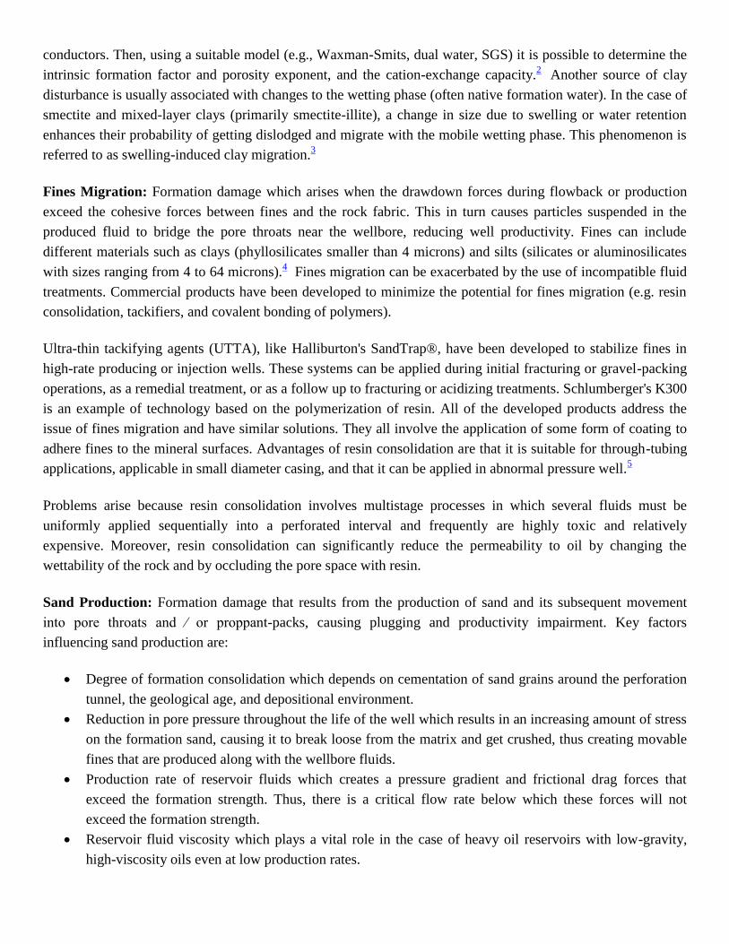
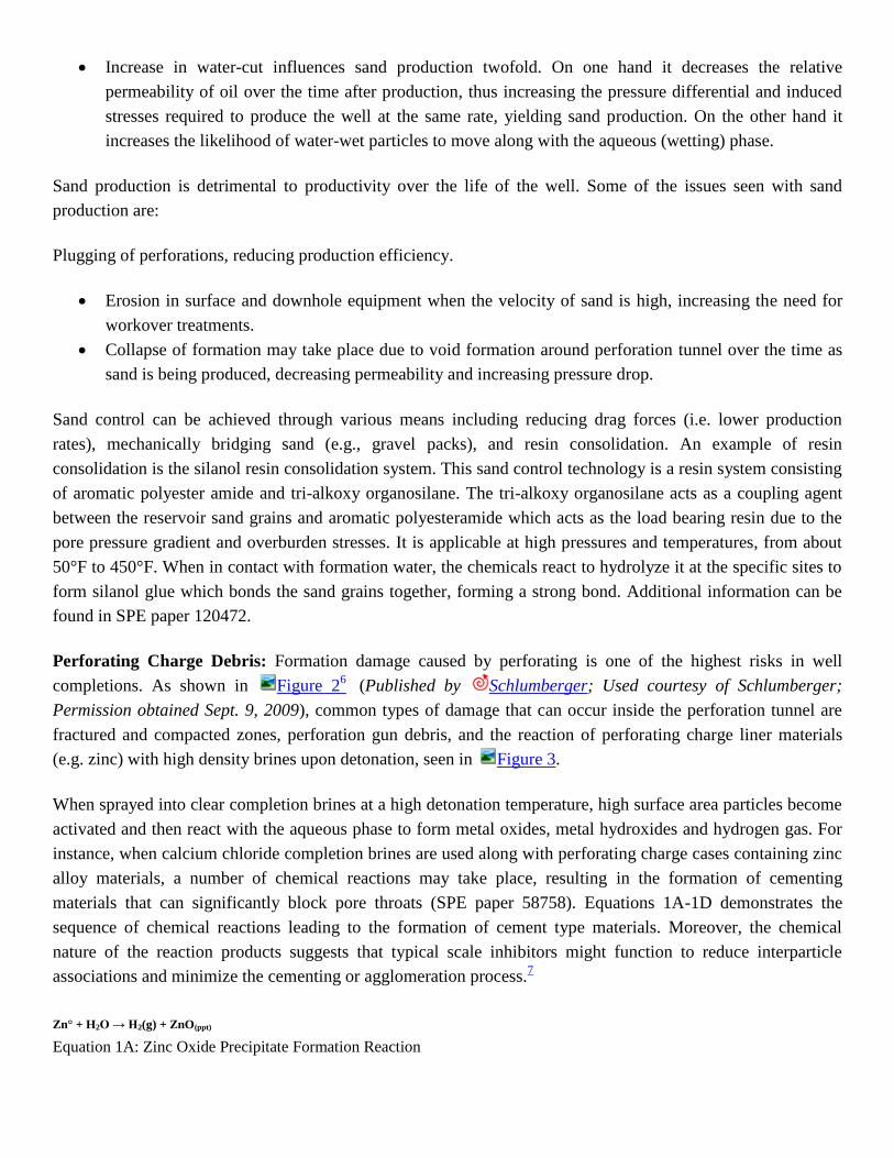

Ca2+
(aq) + SO42-
(aq) rarr CaSO4(s)
Equation 4 Calcium Sulfate Scale Formation Reaction
Temperature is also a factor with higher temperatures lowering the anhydrite solubility and increasing scaling
tendency In seawater injections scale such as anhydrite will become more significant as seawater breakthrough
occurs There are 3 available methods for chemical removal of anhydrite scales1213
Inorganic converters which modifies the scale into an acid soluble byproduct This method will also
remove other acid soluble materials present
Organic converters which converts the scale into a dispersionsludge that is able to flow This method
can include an acid treatment or not The acid treatment will effectively remove the reaction products
because they are soluble in acid
Chelants which work by complexing the Ca2+
ions This method effectively reduces the ions capacity to
re-precipitate Inhibition of anhydrite scale could involve polyphosphonates or polyorganic acid salt
compounds
Halite Scale Salt scale that can be formed during production of high salinity (gt200000 ppm) formation brine
as seen in Figure 8 Halite formation may also occur during the evaporation of water into the gas phase
Halite scale is normally easily removed with periodic fresh or low salinity water flushes Removal can also be
achieved with continuous dilution of the fluid stream with water upstream of where deposition occurs14
Depending on the rate of the salt deposition and the availability of fresh water such flushes could become an
expensive removal method An example of a salt inhibitor used is potassium hexacyanoferrate (HCF) HCF is a
well-known species which has been applied as an anti-caking agent in cooking and as a drilling-fluid additive
for drilling through salt layers where it both limits hole wash-out (because it also reduces the rate of salt
dissolution) and prevents salt from crystallizing from the returned fluid as it cools and becomes supersaturated
in salt15
Iron Sulfide Scale that can occur whenever sources of both iron and hydrogen sulfide are present H2S can
result from the presence of sulfate reducing bacteria thermal sulfate decomposition or introduction to a well
through gas lift operations Iron sulfides are able to enhance the corrosion process decrease productivity and
negatively affect oil-water separation activities Iron sulfide exists in numerous crystalline forms with numerous
acid solubilities The FeS species responds well to HCl treatment but the longer the contact time between FeS
and H2S the more likely that the scale will become richer in sulfur While FeS may be effectively removed with
acid FeS2 is not Since iron sulfide is normally oil-wet scale removal is impeded To correct this adding
surfactants and water-wetting agents is important Acid treatments should also have a corrosion inhibitor an
iron control agent and a hydrogen sulfide scavenger Toxic H2S is produced by the following reaction
(Equation 5) between FeS and HCl
FeS(s) + 2HCl (aq) rarr FeCl2 (aq) + H2S (g)
Equation 5 Hydrogen Sulfide Gas Formation Reaction
FeS will also precipitate as H2S continues to react with any ferrous iron present at pH gt 19 If ferric ion is
present elemental sulfur can precipitate which is insoluble in HCl and needs expensive organic solvents to
remove16
Understanding the source of iron and sulfide is key to preventing iron sulfide scaling Iron can be
present in the formation water or supplied by tubing corrosion If the iron is supplied by tubing corrosion
protecting the metallurgy could reduce the potential for iron sulfide scale If the iron is present in the formation
water the course of action should be to limit the amount of H2S through biocides injection water sulfate ion
minimization or injection of nitrates One chemical treatment option is tetrakis hydroxymethyl phosphonium
(THPS) used to dissolve or chelate iron sulfide once it is formed17
Organometallic
Naphthenates Formation damage caused by fluctuations in the reservoir water pH resulting in the formation
of organic scales carbonate deposits and the stabilization of emulsions Reservoir water is naturally saturated
with CO2 in equilibrium with bicarbonate anion (HCO3-) as shown in the following reaction (Equation 6)
CO2 + 2H2O rarr HCO3- + H3O
+
Equation 6 Reservoir Water Equilibrium
Fluids injected into the well for various procedures can alter the temperature pressure and composition of the
fluids in the near wellbore region Precipitation can occur during production by a chemical reaction of two or
more ions in solution or by changing the temperaturefraslpressure of a saturated solution which causes a drop in
solubility Scale can also precipitate due to the mixing of two incompatible fluids and with the release of CO2
brought on by a pressure reduction
These pressure drops are accompanied by an increase in pH and oftentimes the formation of mixed carbonate
and naphthenate deposits inside tubing or surface installations as well as the creation of stable emulsions due to
the surface-active naphthenate group RCOO- Naphthenic acids R-COOH are often present in crude oils and the
hydrophilic nature of the carboxylic acid group means that they congregate at the oil-water surface18
Examples of their structures
can be seen in Figure 11 Oil and formation water composition is very important in the formation of naphthenates These variables
are naphthenic acid concentration and composition formation water cations bicarbonates and pH Crude oils that present the biggest
complications are ones with high total acid number TAN and high concentrations of naphthenic acid
Naphthenate problems can be exacerbated by the presence of solids such as formation sand and fines waxes and other types of scale
The stability of emulsions containing naphthenic acids has been shown to be a function of pH asphaltenefraslresin ratios naphthenic acid
types and cation content of the aqueous phase Sodium rich emulsions lead to less separated water volume over time showing the
stability of the oil-water emulsion Calcium rich solutions lead to less stable emulsions possibly due to excess ionic strength in
solution Sarac and Civan19
determined through experimentation that the critical minimum initial brine pH required for the onset of
naphthenate precipitation to be 591 As pressure drops occur during production degassing of CO2 takes place raising the pH of the
formation brine and promoting the dissociation of naphthenic acids as shown in Equation 7
R-COOH + OH- rarr R-COO
- + H2O
Equation 7 Naphthenic Acid Dissociation
The naphthenate ion is very reactive and tends to complex with Na+ and Ca
2+ cations to form sodium and
calcium naphthenate scales as shown in Equation 8 and Equation 9 Naphthenate deposits normally collect in oil
frasl water separators but can deposit in tubing and pipelines as well
2R-COO- + Ca
2+ rarr (R-COO)2Ca
Equation 8 Calcium Naphthenate Formation
R-COO- + Na
+ rarr R-COONa
Equation 9 Sodium Naphthenate Formation
Due to its high molecular weight calcium naphthenate is less soluble than sodium naphthenate in water This is
important because when calcium carbonate and calcium naphthenate form together the carbonate will decrease
the formation of naphthenate This is due to the reduction in available calcium cations for reactions with the
naphthenate anions When evaluating the stability of emulsion and the amount of naphthenate deposits during
processing of acidic crude it is important to take into account the following criteria
1 Water pH value at process conditions as well as the level of bicarbonate and calcium content at reservoir
conditions
2 Total Acid Number (TAN) of crude oil20
TAN is the amount of any acid contained in an oil sample
While the test is unable to determine specific types of acids it is useful in determining if a sample of oil
will be corrosive or not The threshold for corrosive oils is 05 mg KOHfraslg oil Acidizing with HCl and frasl
or acetic acid is often used to remove naphthenate deposits An example of naphthenate deposits can be
seen in Figure 12 Additional information on naphthenate formation prevention and mitigation can be
found in SPE papers 93407 80395 112434 and 68307
Organic
Asphaltenes amp Parrafins Formation damage resulting from organic deposit which hamper the production of
crude oil Paraffins are alkanes of relatively high MW (C18 to C70) which can be either straight-chained or
branched They have specific solubilities and melting points Because these hydrocarbons have satisfied valence
electron configurations they are almost completely inert to chemical reactions and as a result immune to
attack by bases and acids
Paraffin waxes are soluble in most liquid petroleum fractions and their solubility normally decreases as MW
increases Hence they are soluble in both straight-chain and aromatic petroleum derivatives They are deposited
as solids when the temperature drops below the cloud point for the particular crude oil SARA analysis can be
performed to determine the different constituents present in oil SARA is a method for characterization of oils
based on fractionation whereby a heavy oil sample is separated into smaller quantities or fractions with each
fraction having a different composition
Fractionation is based on the solubility of hydrocarbon components in various solvents used in the test Each
fraction consists of a solubility class containing a range of different molecular-weight species In this method
the oil is fractionated to four solubility classes referred to collectively as SARA Saturates-Aromatics- Resins-
Asphaltenes
Saturates are generally paraffins while aromatics resins and asphaltenes form a continuum of molecules with
increasing molecular weight aromaticity and heteroatom contents Products like Halliburtons Parachekreg 160
a polymeric paraffin inhibitor alter the paraffin structure decreasing its tendency to precipitate21
Common
solvents used for paraffin removal include condensate kerosene and diesel (straight-chain hydrocarbons)
Asphaltenes on the other hand are black polycyclic aromatic complex compounds seen in Figure 5
Published by Experimental Soft Condensed Matter Group ( Harvard) Permission to use obtained Aug 3
2009 Generally they are spherical 30Aring to 65Aring in diameter with MW of 10000 to 100000
These molecules are held in suspension by surrounding asphaltic resins (maltenes) Asphaltenes polar
properties result from the presence of oxygen sulfur nitrogen and various metals in their structures Figure 7
shows the blockage that can occur resulting in severe damage Published by London Center for
Nanotechnology Permission to use obtained Sept 9 2009 Deposition occurs not only by temperature frasl
pressure reductions but also by destabilizing factors which act on the resins such as contact with acid CO2 or
aliphatic solvents that act on the micellar colloidal suspension to strip away the maltene and resin from the
micelles Removal is possible but selecting the appropriate method is crucial and can be accomplished by field
tests
While condensate kerosene and diesel are commonly used to dissolve paraffin they should not be used when
attempting to remove asphaltenes These non-aromatic hydrocarbons if used can cause further precipitation of
the asphaltenes as the maltene stabilizers are disturbed Instead aromatic chemicals such as xylene can be used
Their power can be enhanced by almost ten times with the addition of approximately 5 by volume of a
specific primary or secondary amine such as Halliburtons highly polar organic Targonreg II22
Closely
monitored due to low flash points moderate heating will hasten the removal process New solvents that are
non-toxic biodegradable and work similarly are available such as Dowell Schlumbergers PARAN ECOreg
Another asphaltene solvent is Tretolites Paridreg PD-72 which is a mixture of toluene and a surfactant While
continuous or batch pumping methods are employed the batch method is recommended with the solvent left in
contact with the asphaltenes for up to 24 hours Common methods for organics scale removal are mechanical
solvents heat and dispersants
Hydrates Hydrates are solid white crystalline substances with cellular structures formed as a result of water
vapors and gaseous hydrocarbons interaction in the presence of water and under high pressure and low
temperature conditions (T gt 32deg F) as shown in Figure 9 There are three common types of gas hydrate
inhibitors thermodynamic kinetic and crystal size modifiers Thermodynamic inhibitors (eg inorganic and
organic salts glycerol or low molecular weight glycol combination of salt and glycol) work upon injection by
preventing the formation of hydrogen bonds or destroying them Kinetic inhibitors (eg polymers and
surfactants) work as a slow reaction to delay nucleation or slow the crystal growth rate Crystal size modifiers
also known as crystal habit modifiers do not prevent hydrate formation Instead they act as anti-agglomerates
to ensure that hydrates form a pumpable slush so that fluid flow is maintained
Bacterial Growth
Formation damage that is caused by the introduction of bacteria while aqueous phase fluids are utilized and
improper bacteriological control is maintained Bacterially induced formation damage is a particularly insidious
type of formation damage in that the apparent harmful effects of the introduction of the bacterial agents are
usually not noticed until well construction materials fail catastrophically Bacteria which cause formation
damage can be classified into two types aerobic and anaerobic Aerobic bacteria require a constant source of
oxygen to survive and are mainly problematic with long term water injection operations Anaerobic bacteria do
not require oxygen and tend to be more widespread and problematic Both types present issues with plugging
corrosion and toxicity23
Corrosion is caused by anaerobic bacteria sulfate reducers which digest sulfate in
water to produce corrosive hydrogen sulfide The resulting iron sulfide corrosion product particularly in
combination with small amounts of oil can significantly plug water treatment and injection facilities Slug
treatments with bactericide are usually effective in controlling the anaerobic sulfate reducers24
Other
alternatives (still in early development stages) rely on the use of phage cocktails to target specific bacteria
within the reservoir andor in pipe lines25
Polymer Plugging
Formation damage caused by the addition of polymers typically used to provide clay stability and frasl or control
fluid losses during drill-in and completion operations Chemical fluid loss control (FLC) materials can be
grouped into two categories solids laden and solids free Sized salts calcium carbonate and organosoluble
resins are three types of solids typically used as FLC materials Solids free FLC pills on the other hand may
consist of linear gels (eg Liqui-Visreg and Bromi-Visreg) crosslinked gels as seen in Figure 13 (eg K-
Maxtrade Max Sealtrade TekPlugtrade and Protectozonetrade) and the more recently developed viscoelastic surfactant
gels (eg ClearFractrade)
Solids Laden FLC The most widely used solids laden FLC materials consist of sized CaCO3 particles
suspended in a polymer matrix Computer software is used to determine the optimum CaCO3 loading
and particle size distribution to form a seal against the formation rock and minimize fluid losses The pill
can be either bullheaded or spotted with a coil tubing unit The pill is usually removed with an acid
treatment (eg HCl or HClfraslacetic) Other clean-up alternatives include breaker systems (internal or
external) based on polymer-specific enzymes and frasl or chelating agents An alternative to the calcium
carbonatefraslpolymer system particularly for injector wells is the saltfraslpolymer system which consists of
ground sodium chloride in saturated NaCl brine frasl polymer matrix Since sodium chloride is readily
soluble in water produced water or unsaturated brine treatments will afford removal of residual salt
solids Depending on the polymer uploading in the FLC pill an acid treatment may also be required
Santrols Collagen or synthetic polymer balls are also readily dissolved in the presence of unsaturated
brines and thus constitute another alternative for water-soluble FLC materials particularly for injector
wells26
Oil soluble resins such as benzoic flakes may be used as FLC materials in low to moderate
temperature producer wells Resins are typically added to completion brines and delivered to the
formation where they plate out onto rock surfaces After the completion operation is finished produced
oil or condensate flowing over the resin gradually dissolves it As with the introduction of any foreign
fluid into the formation there are advantages and disadvantages to be evaluated before using a FLC
material Table 3 highlights the strengths limitations and costs of the three general types of bridging
solids used for FLC
Particulate Strengths Limitations Cost
CaCO3 frasl
Polymer
Inexpensive
Relatively easy to mix
Good for bridging on gravel and
frac packs
Used when lower densities are
required
Can plug perforation tunnels
Highly damaging if particles are not sized
properly
Polymer damage may require remedial
treatments
May cause tools to stick
Degradation depends upon contact with
acid for removal
Relatively
low
NaCl frasl
Polymer
Relatively easy to mix
Good for bridging on gravel and
frac packs
Water soluble particles
Can plug perforation tunnels
Highly damaging if particles are not sized
properly
Polymer damage may require remedial
treatments
May cause tools to stick
Low
Oil Soluble
Resin
Easy to mix
Good for bridging on gravel and
frac packs
Water soluble particles
May not stop losses completely
Not useful above melting point
Only recommended in oil wells
Relatively
low
Table 3 Bridging Particulate Systems Strengths Limitations amp Costs
Solids Free FLC Linear gels can be prepared from a range of polymer systems most typically natural
polymers or natural polymers that have been modified to achieve the necessary purity and solution properties
The chemical structure of common polymers used as FLC materials and viscosifiers are shown in figures 14A-
14F Cellulose Figure 14A is a natural structural component of wood and in cotton it exists in nearly pure
form However cellulose is insoluble in water and brines To make this polymer soluble it is usually
derivatized to hydroxyethyl cellulose (HEC) Figure 14B which is relatively easy to disperse and hydrate in
most brine solutions Xanthan polymer Figure 14C is a more complex system with excellent solids
transport and suspending characteristics particularly at low shear rates Note that xanthan has pendant carboxyl
groups which can bind to contaminant ions to produce difficult-to-break gels Additionally xanthan polymer
systems are incompatible with many biocides and clay stabilizers Linear polymer gels are useful in operations
involving low overbalance low temperature low permeability and short interval length More recently
viscoelastic surfactants (VES) have been developed as an alternative to polymer-based FLC materials VES
impart viscosity to the fluid by forming a 3D network of rod-like micellar structures show in Figure 14E
The advantage of viscoelastic surfactants is that they need no added breakers to reduce viscosity after use
Viscosity is degraded when contact is made with oil whereby the micelles are disrupted and the viscosifying
network is destroyed Another benefit of the particles is the formation of a pseudo filter cake of viscous VES
fluid that greatly decreases fluid loss rates and improves overall efficiency of the fluid Table 4 lists the
strengths limitations and cost of some available linear gel systems and VES New technology has led to the
introduction of nanometer-scale particles which interact with VES micelles through chemisorptions and
surface charge attraction to form a worm-like micellular structure as seen in Figure 14F (Published by
Schlumberger - Used courtesy of Schlumberger Permission obtained September 9 2009) Such interactions
stabilize fluid viscosity at high temperatures As internal breakers are activated to break the micelles the fluid
drastically loses its viscosity and the pseudo filter cake dissolves into nanometer-sized particles Since these
particles are so small they are easily carried back to the surface thus minimizing formation damage potential
SPE paper 107728 provides more information on the new VES system
Polymer Strengths Limitations Cost
Hydroxyethyl Cellulose
(HEC)
Relatively easy to mix
Readily available
Non-toxic non-corrosive
Acid soluble
Internally or externally
broken
Highly damaging if not pumped
correctly
Does not stop losses completely
Requires multiple treatments
Requires shearing and filtering
Relatively
inexpensive
Xanthan (XC) Relatively easy to mix
Readily available
Non-toxic non-corrosive
Good low-shear viscosity
Highly damaging if not pumped
correctly
Does not stop losses completely
Requires multiple treatments
Requires filtering
Not readily removed with acid
Relatively
inexpensive
Succinoglycan Easy to mix
Non-toxic non-corrosive
Good low-shear viscosity
Does not stop losses completely
Requires multiple treatments
Requires filtering
Temperature limitations
Moderately
expensive
Viscoelastic Surfactant
(VES)
Easy to mix
No solids
Good low-shear viscosity
Requires hydrocarbon contact to
break
Temperature limitations
Relatively
expensive
Table 4 Linear Gel Systems (Polymers) Strengths Limitations amp Cost
Figure 15 shows a comparison of rheological properties of HEC and xanthan (XC) polymer As seen in this
figure XC polymer displays a higher low shear rate viscosity (LSRV) compared to HEC which translates in
better solids carrying capacity at low flow rates and under static (no flow) conditions On the other hand HEC
is easier to remove via the use of internal breakers and frasl or remedial acid treatments To achieve higher
viscosities crosslinked polymer systems are typically employed Crosslinked gels are typically compromised of
derivatized HEC and are useful at temperatures up to 300deg F They are available as pre-blended products or can
be prepared on the rig Crosslinking agents for HEC include zirconium and lanthanide salts Crosslinked gel
particulates in the form of premanufactured slurries are oftentimes useful when more complete fluid loss
control is needed Max Sealtrade slurries for example can effectively plug off formations under relatively high
overbalanced pressures It is comprised of crosslinked HEC gel which has been chopped up to form
inhomogeneous lumpy flowing slurry Table 5 lists some crosslinked gel systems along with their strengths
limitations and relative cost
Crosslinked Strengths Limitations Cost
Crosslinkable HEC Stops losses completely
Easily removed with breakers
Can withstand high overbalanced
pressures
Can run tools through it
Internal breakers used for le
48 hrs
(fluid begins to degrade with
time)
Must be mixed on location
Moderately expensive
Pre-Prepared
Crosslinked
Gel Particles
Stops losses completely
No on-site mixing required
Can withstand high overbalanced
pressures
Can run tools through it
No internal breakers can be
added
(must be broken externally)
Bulky to ship and store
Moderately expensive
to high
Zinc Bromide
Crosslinked Gel Stops losses completely
Only pumpable system available
for ZnBr2
Must be mixed on site
Must be broken externally
High
Table 5 Cross linked Gel Systems (Polymers) Strengths Limitations amp Cost
Another potential source of formation damage from polymer plugging is that related to clay stabilization via the
use of polymers The polymers include cationic inorganic polymers (CIP) and cationic organic polymers (COP)
CIP such as hydroxyl aluminum and zirconium oxychloride provide marginally permanent clay stabilization
They offer resistance to cation exchange but their application is limited to noncarbonate-containing sandstones
Cationic organic polymers are effective in providing permanent stabilization to clays especially smectite and
for controlling fines and sand in sandstone and carbonates formations Permanent protection is provided by the
availability of multiple cationic sites of attachment but their application is limited to low concentrations COP
are applicable in acidizing and fracturing but their effectiveness is lowered in gelled-water solutions used for
hydraulic fracturing and gravel-packing due to gel competition for adsorption on clay surfaces27
They are often
the cause of formation damage via polymer plugging because of their high molecular weight and long chains
that have molecular sizes similar to pore throats in porous rock Figure 16 shows a scanning electron
micrograph detailing solids and polymer plugging of pore throats
Altered Wettability
Formation damage in which the formation wettability is modified generating a change in relative permeability
to oil gas and frasl or water that eventually affects well productivity In particular surfactants and other additives in
drilling fluids especially oil-base mud can change a naturally water-wet formation to an oil-wet formation with
consequent production impairment caused by reduction of relative permeability to oil andor gas Brine salinity
and pH are another important factor related to wettability because they strongly affect the surface charge density
on the formation rock and fluid interfaces which in turn can affect surfactants adsorption Figure 17 shows
an SEM of water droplets on both kaolinite and quartz illustrating the contrasting wetting characteristics of
different mineral surfaces Published by University of the West of Scotland No further reproduction please
use for this project webpage only Permission to use obtained Aug 5 2009 Relative permeability modifiers
such as Halliburtons WaterWebreg and BJ Services AquaContrade are hydrophilic polymers designed to reduce
the effective permeability to water while increasing (or maintaining) the relative permeability to gas and frasl or
oil They do not typically require special placement techniques
Water Block
Formation damage that occurs when large quantities of water andor brine are lost to the formation thus
increasing water saturation and decreasing the relative permeability to oil andor gas Partially pressure-depleted
reservoirs are particularly sensitive to this type of damage Water blocking can be prevented frasl minimized by
adding surface tension reducing agents (eg surfactants alcohols or microemulsions) to wellbore fluids to not
only lower surface and interfacial tension but also to water-wet the formation and prevent emulsions28
Emulsions
Formation damage that is a mixture of two or more immiscible liquids in which the liquids are stabilized by
one or more emulsifying agents If an emulsion block exists well permeability as determined through injectivity
test will be much greater than permeability determined through production tests Oilfield emulsion types consist
of water in oil (regular emulsions) oil in water (reverse emulsions) and complex emulsions Most emulsions
break easily when the source of the mixing energy is removed However some natural and artificial stabilizing
agents such as surfactants and small particle solids keep fluids emulsified Natural surfactants created by
bacteria or during the oil generation process can be found in many waters and crude oils while artificial
surfactants are part of many drilling completion or stimulation fluids Among the most common solids that
stabilize emulsions are iron sulfide paraffin sand silt clay asphalt scale and corrosion products29
More
information regarding emulsions can be found in SPE papers 105858 100430 and 97886
References
1Allen Thomas O and Roberts Alan P Production Operations 2 OGCI Tulsa Oklahoma 2000
2Allen Thomas O and Roberts Alan P Production Operations 2 OGCI Tulsa Oklahoma 2000
3Allen Thomas O and Roberts Alan P Production Operations 2 OGCI Tulsa Oklahoma 2000
4Schlumberger Oilfield Glossary
5Allen Thomas O and Roberts Alan P Production Operations 2 OGCI Tulsa Oklahoma 2000
6Schlumberger Perforation Damage
7Javora PH Ali SA and Miller R Controlled Debris Perforating Systems Prevention of an Unexpected Source of Formation Damage SPE 58758
2000
8 McElfresh PM Gabrysch AD Van Sickle E Myers Jr B and Huang T A Novel Method of Preventing Perforation Damage in High-Temperature
Offshore Wells SPE 86521 2004
9Civan Faruk Reservoir Formation Damage 2nd Ed Elsevier Inc Oxford UK 2007
10Thane CG SMAD-Mafumeira Drilling Completions and Production Formation Damage Review and Recommendations Block 0 Angola TM 2008-27
2008
11Jordan MM Collins IR Gyani A and GM Graham Coreflood Studies Examine New Technologies That Minimized Intervention Throughout Well Life
Cycle SPE 74666 2006
12Jewell RJ and BR Lasater New Products to Solve Scale Problems SPE 3550 1971
13OJ Vetter Oilfield Scale ndash Can We Handle It SPE 5879 1976
14Frigo DM Jackson LA Doran SM and RA Trompert Chemical Inhibition of Halite Scaling in Topsides Equipment SPE 60191 2001
15Earl SL Use of Chemical Salt Precipitation Inhibitors to Maintain Supersaturated Salt Muds for Drilling Salt Formations SPE 10097 1981
16Nasr-El-Din HA and AA Al-Taq Water Quality Requirement and Restoring the Injectivity of Waste Water Disposal Wells SPE 68315 1998
17Nasr-El-Din HA Roser HR and Al-Jawfi M Formation Damage Resulting from BiocidefraslCorrosion Squeeze Treatments SPE 58803 2000
18Dyer SJ Graham GM and Arnott C Naphthenate Scale Formation ndash Examination of Molecular Controls in Idealised Systems SPE 80395 2003
19Sarac S and Civan F Mechanisms Parameters and Modeling of Naphthenate Soap-Induced Formation Damage SPE 112434 2008
20Rousseau G Zhou H and Hurtevent C Calcium Carbonate and Naphthenate Mixed Scale in Deep-Offshore Fields SPE 68307 2001
21Parachekreg 160 Paraffin Inhibitor Chemical Compliance 08 Jan 2008 Halliburton 29 May 2009
22Targonreg II Asphaltene Solvent Chemical Compliance 08 Jan 2008 Halliburton 29 May 2009
23Bennio DB et al Mechanisms of Formation Damage and Permeability Impairment Associated with the Drilling Completion and Production of Low API
Gravity Oil Reservoirs SPE 30320 1995
24Allen Thomas O and Roberts Alan P Production Operations 2 OGCI Tulsa Oklahoma 2000
25Phage Biocontrol Inc
26Santrol Oil amp Gas Stimulation Products
27Civan Faruk Reservoir Formation Damage 2nd Ed Elsevier Inc Oxford UK 2007
28Allen Thomas O and Roberts Alan P Production Operations 2 OGCI Tulsa Oklahoma 2000
29Schlumberger Oilfield Glossary
Last Update 21 September 2009

Recommended