12/10/17
1
Medium Access Control
Mark HandleyUCL Computer Science
CS 3035/GZ01
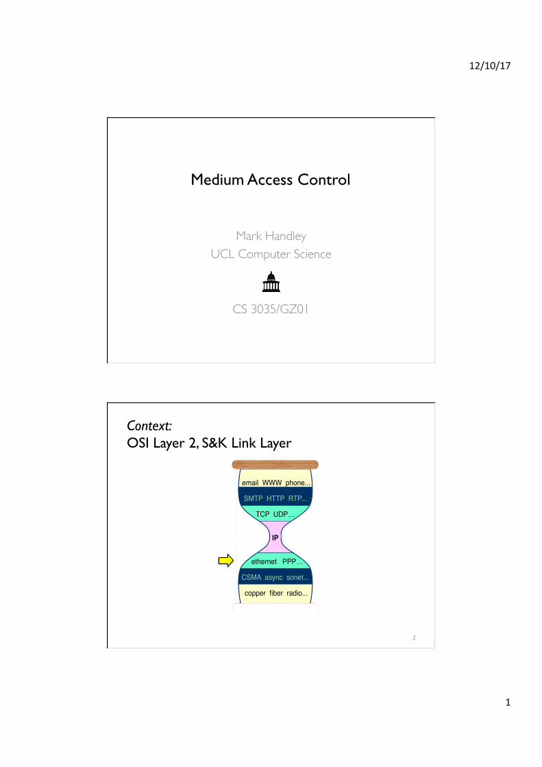
Context: �OSI Layer 2, S&K Link Layer
email WWW phone...!
SMTP HTTP RTP...!
TCP UDP…!!
IP!!
ethernet PPP…!
CSMA async sonet...!
copper fiber radio...!
2
12/10/17
2
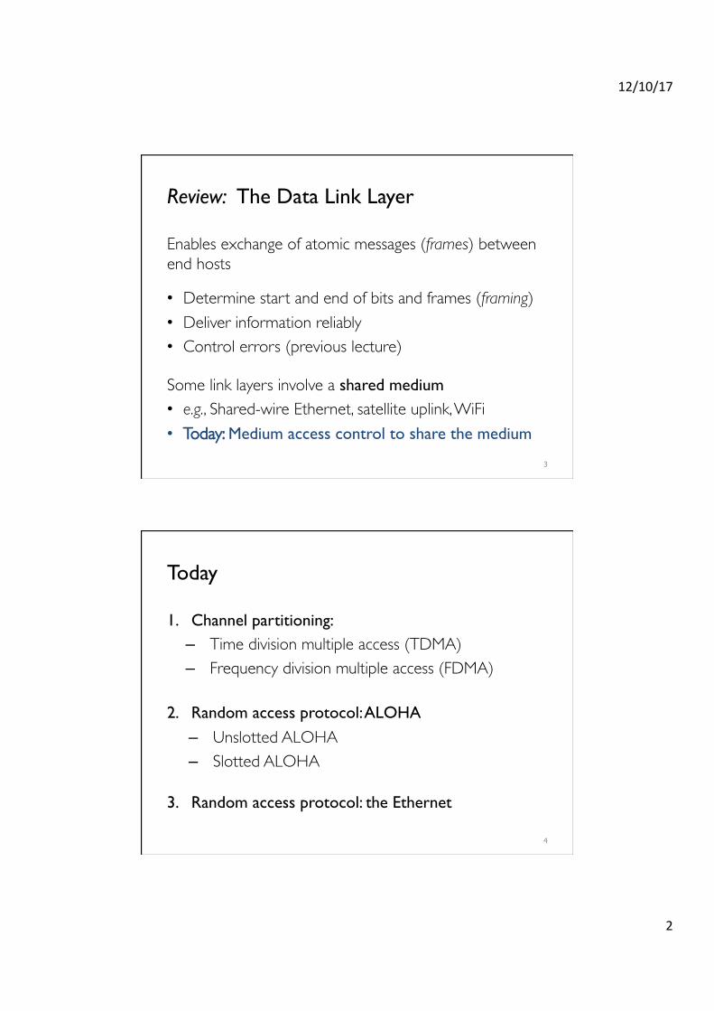
Review: The Data Link Layer
Enables exchange of atomic messages (frames) between end hosts
• Determine start and end of bits and frames (framing)• Deliver information reliably• Control errors (previous lecture)
Some link layers involve a shared medium• e.g., Shared-wire Ethernet, satellite uplink, WiFi• Today: Medium access control to share the medium
3
Today
1. Channel partitioning: – Time division multiple access (TDMA)– Frequency division multiple access (FDMA)
2. Random access protocol: ALOHA
– Unslotted ALOHA– Slotted ALOHA
3. Random access protocol: the Ethernet
4
12/10/17
3
Today
1. Channel partitioning: – Time division multiple access (TDMA)– Frequency division multiple access (FDMA)
2. Random access protocol: ALOHA
– Unslotted ALOHA– Slotted ALOHA
3. Random access protocol: the Ethernet
5
Circuit Switching
6
12/10/17
4
Multiplexing
• Typically multiple data circuits are multiplexed onto one physical circuit.– Don’t need one pair of wires for each phone call.
• Can multiplex in time or in frequency:– TDMA – time– FDMA – frequency.
7
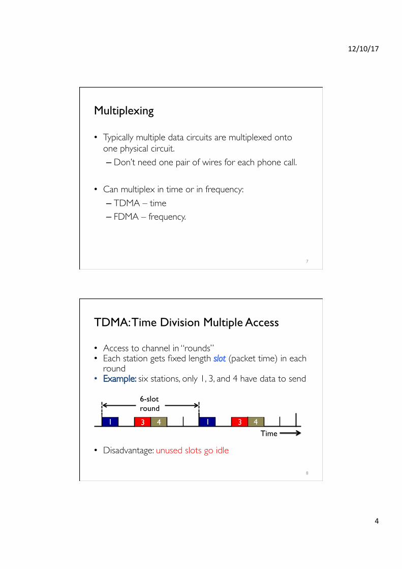
TDMA: Time Division Multiple Access
• Access to channel in “rounds” • Each station gets fixed length slot (packet time) in each
round• Example: six stations, only 1, 3, and 4 have data to send
• Disadvantage: unused slots go idle
8
1 3 4 1 3 4
6-slotround
Time
12/10/17
5
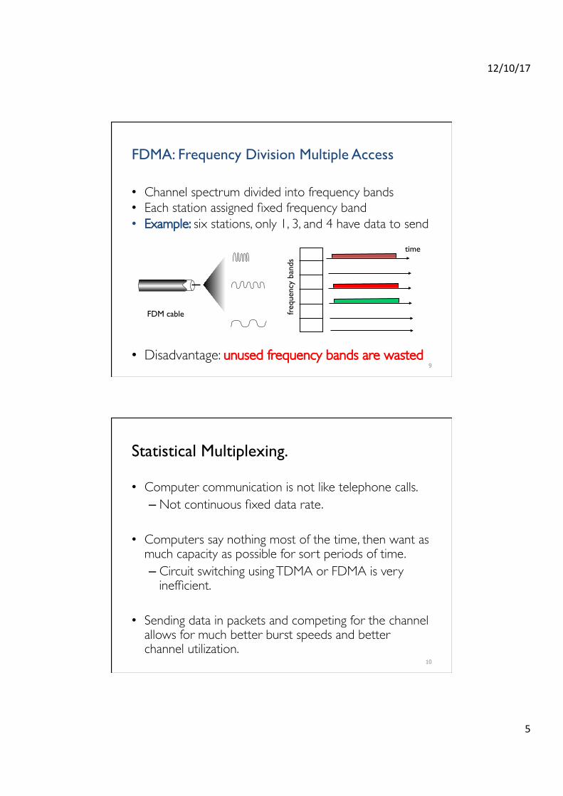
FDMA: Frequency Division Multiple Access
• Channel spectrum divided into frequency bands• Each station assigned fixed frequency band• Example: six stations, only 1, 3, and 4 have data to send
• Disadvantage: unused frequency bands are wasted9
freq
uenc
y ba
nds
time
FDM cable
Statistical Multiplexing.
• Computer communication is not like telephone calls.– Not continuous fixed data rate.
• Computers say nothing most of the time, then want as much capacity as possible for sort periods of time.– Circuit switching using TDMA or FDMA is very
inefficient.
• Sending data in packets and competing for the channel allows for much better burst speeds and better channel utilization.
10

12/10/17
6
Medium Access: the Problem
Two questions:1. How should the shared medium be divided?2. Who gets to talk on a shared medium, and when?
A medium access control (MAC) protocol specifies who should talk when, and so dictates how to share the medium.
11
Goals of a MAC protocol
1. Efficiency• High throughput (bits/second successfully received
through the channel)• High utilization (throughput/raw channel rate)
2. Fairness:
• all hosts with data to send should get a roughly equal share of the medium over time
3. Latency: • want to minimize the time a host waits before being
granted permission to talk on the shared medium
12
12/10/17
7
Today
1. Channel partitioning: – Time division multiple access (TDMA)– Frequency division multiple access (FDMA)
2. Random access protocol: ALOHA
– Unslotted ALOHA– Slotted ALOHA
3. Random access protocol: the Ethernet
13
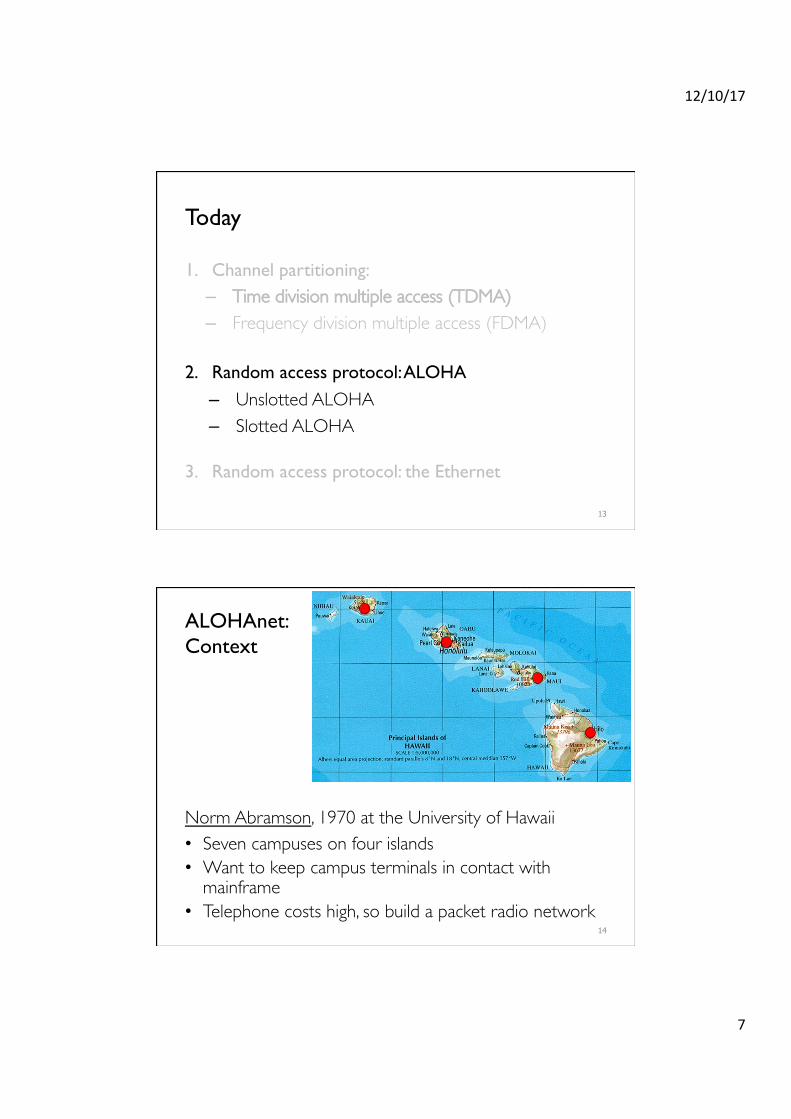
ALOHAnet: �Context
Norm Abramson, 1970 at the University of Hawaii• Seven campuses on four islands• Want to keep campus terminals in contact with
mainframe• Telephone costs high, so build a packet radio network
14

12/10/17
8
Random Access MAC Protocols
• When a host has a frame to send:– Transmit at full channel data rate B– No a priori coordination among nodes
• Two or more frames overlapping in time: collision– Both frames are lost, resulting in diminished throughput
• A random access MAC protocol specifies: – How to detect collisions (if medium supports doing so!)– How to recover from collisions
15
Unslotted ALOHA
• Simplest possible medium access control: no control at all, anyone can just transmit a packet without delay
• Let’s assume that the probability a packet begins in any time interval of length Δt is λ × Δt – N senders in total, sending frames of time duration 1 – This is called a Poisson process with rate λ • λ is the aggregate rate from all N senders• Individual rate λ/N for each sender
16
Time
Node 3
Node 2
Node 1

12/10/17
9
Unslotted ALOHA: Performance• Suppose some node i is transmitting; let’s focus on i’s frame
17
1. If others start sending between t0−1 and t0, their frames will overlap with the start of i’s frame ! collision
2. If others start sending between t0 and t0+1, their frames will overlap with end of i’s frame ! collision
3. Otherwise, no collision, and node i’s frame is delivered
Therefore, there is a “vulnerable period” of length 2 around i’s frame
nodei’sframe
t0t0-1 t0+1
otherframe
overlapswithstartofi’sframe
otherframe
overlapswithendofi’sframe
vulnerableperiod
Unslotted ALOHA: Performance
18
Pr no send from one node in 2( ) =1− 2λN
Pr no send at all in 2( ) = 1− 2λN
"
#$
%
&'N−1
limN→∞
1− 2λN
"
#$
%
&'N−1
→ e−2λ
What’s the chance no one else sends in the vulnerable period of length 2?
€
limx→∞
1+1x
$
% &
'
( ) x
= e
nodei’sframe
t0t0-1 t0+1
otherframe
overlapswithstartofi’sframe
otherframe
overlapswithendofi’sframe
vulnerableperiod

12/10/17
10
Unslotted ALOHA: Utilization
19
Recall from our definition of the Poisson process: λ is the aggregate rate from all senders
So, utilization= λ × Pr(no other transmission in 2) = λe−2λ
λ
U$liza$on1/2e≈18%
Toomanycollisions!
Notsendingfastenough
Today
1. Channel partitioning: – Time division multiple access (TDMA)– Frequency division multiple access (FDMA)
2. Random access protocol: ALOHA
– Unslotted ALOHA– Slotted ALOHA
3. Random access protocol: the Ethernet
20
12/10/17
11
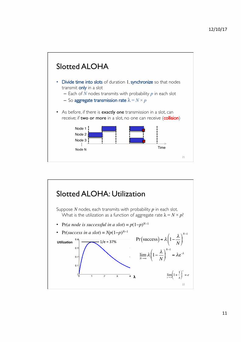
Slotted ALOHA
• Divide time into slots of duration 1, synchronize so that nodes transmit only in a slot– Each of N nodes transmits with probability p in each slot– So aggregate transmission rate λ = N × p
• As before, if there is exactly one transmission in a slot, can receive; if two or more in a slot, no one can receive (collision)
21
Time
Node 3
Node 2
Node 1
...
NodeN
Slotted ALOHA: Utilization
Suppose N nodes, each transmits with probability p in each slot. What is the utilization as a function of aggregate rate λ = N × p?
• Pr(a node is successful in a slot) = p(1−p)N−1
• Pr(success in a slot) = Np(1−p)N−1
22
Pr success( ) = λ 1− λN
"
#$
%
&'N−1
limN→∞
λ 1− λN
"
#$
%
&'N−1
= λe-λ
λ
1/e≈37%U$liza$on
€
limx→∞
1+1x
$
% &
'
( ) x
= e
12/10/17
12
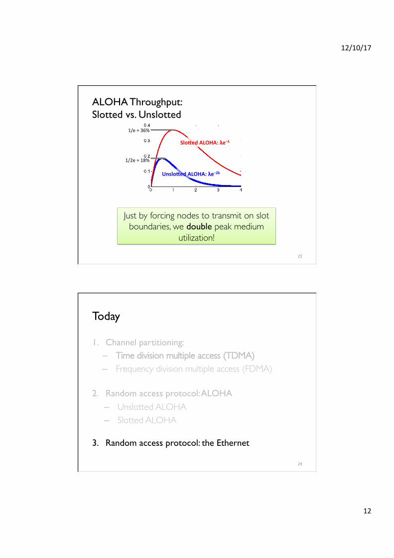
ALOHA Throughput: �Slotted vs. Unslotted
23
Unslo9edALOHA:λe−2λ
Slo9edALOHA:λe−λ
1/2e≈18%
1/e≈36%
Just by forcing nodes to transmit on slot boundaries, we double peak medium
utilization!
Today
1. Channel partitioning: – Time division multiple access (TDMA)– Frequency division multiple access (FDMA)
2. Random access protocol: ALOHA
– Unslotted ALOHA– Slotted ALOHA
3. Random access protocol: the Ethernet
24
12/10/17
13
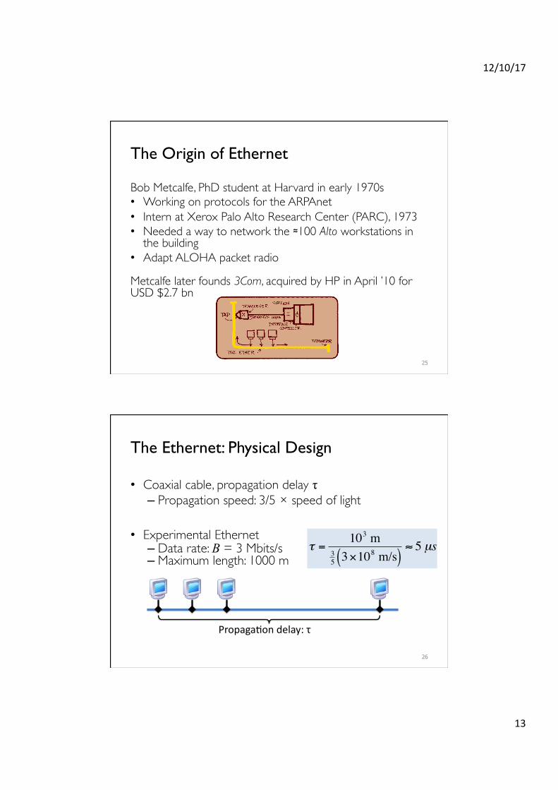
The Origin of Ethernet
Bob Metcalfe, PhD student at Harvard in early 1970s• Working on protocols for the ARPAnet• Intern at Xerox Palo Alto Research Center (PARC), 1973• Needed a way to network the ≈100 Alto workstations in
the building• Adapt ALOHA packet radio
Metcalfe later founds 3Com, acquired by HP in April ’10 for USD $2.7 bn
25
The Ethernet: Physical Design
• Coaxial cable, propagation delay τ – Propagation speed: 3/5 × speed of light
• Experimental Ethernet– Data rate: B = 3 Mbits/s– Maximum length: 1000 m
26
PropagaHondelay:τ€
τ =103 m
35 3×10
8 m/s( )≈ 5 µs
12/10/17
14
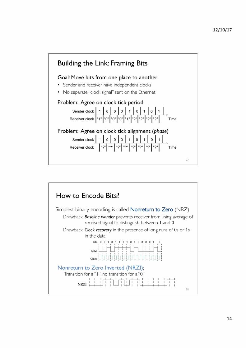
Building the Link: Framing Bits
Goal: Move bits from one place to another• Sender and receiver have independent clocks• No separate “clock signal” sent on the Ethernet
Problem: Agree on clock tick period
Problem: Agree on clock tick alignment (phase)
27
Time
1 0 0 0 1 10Sender clock 0 1
Receiver clock "1" "0" "0" "0" "1" "?" "?" "?" "?"
Time
1 0 0 0 1 10Sender clock 0 1
Receiver clock "?" "?" "?" "?" "?" "?" "?" "?"
How to Encode Bits?
Simplest binary encoding is called Nonreturn to Zero (NRZ)Drawback: Baseline wander prevents receiver from using average of
received signal to distinguish between 1 and 0 Drawback: Clock recovery in the presence of long runs of 0s or 1s
in the data
28
Nonreturn to Zero Inverted (NRZI): Transition for a “1”, no transition for a “0”
12/10/17
15
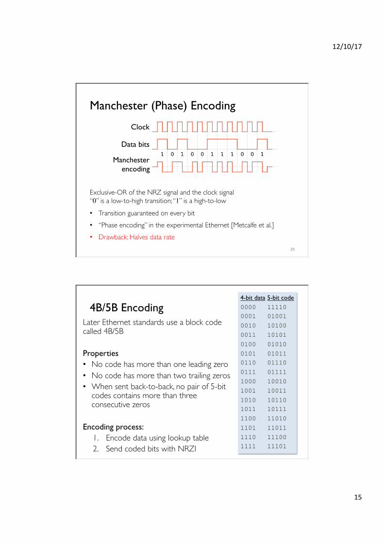
Manchester (Phase) Encoding
29
Exclusive-OR of the NRZ signal and the clock signal“0” is a low-to-high transition; “1” is a high-to-low
• Transition guaranteed on every bit• “Phase encoding” in the experimental Ethernet [Metcalfe et al.]• Drawback: Halves data rate
Clock
Data bits
Manchesterencoding
4B/5B EncodingLater Ethernet standards use a block code called 4B/5B
Properties• No code has more than one leading zero• No code has more than two trailing zeros• When sent back-to-back, no pair of 5-bit
codes contains more than three consecutive zeros
Encoding process:1. Encode data using lookup table2. Send coded bits with NRZI 30
4-bit data0000 0001
0010
0011
0100
0101 0110
0111
1000
1001
1010 1011
1100
1101
1110 1111
5-bit code11110 01001
10100
10101
01010
01011 01110
01111
10010
10011
10110 10111
11010
11011
11100 11101
12/10/17
16
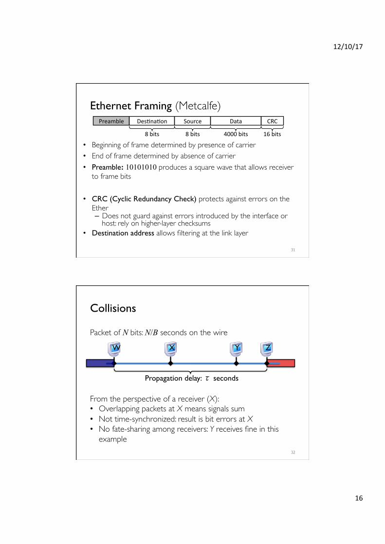
Ethernet Framing (Metcalfe)
• Beginning of frame determined by presence of carrier• End of frame determined by absence of carrier• Preamble: 10101010 produces a square wave that allows receiver
to frame bits
• CRC (Cyclic Redundancy Check) protects against errors on the Ether– Does not guard against errors introduced by the interface or
host: rely on higher-layer checksums• Destination address allows filtering at the link layer
31
Preamble DesHnaHon Source Data CRC
8bits 8bits 16bits4000bits
Collisions
Packet of N bits: N/B seconds on the wire
From the perspective of a receiver (X):• Overlapping packets at X means signals sum• Not time-synchronized: result is bit errors at X• No fate-sharing among receivers: Y receives fine in this
example32
W X Y Z
Propagation delay: τ seconds
12/10/17
17
Who Gets to Transmit?
Carrier Sense Multiple Accesswith Collision Detection (CSMA/CD)
1. Begin the transmission procedure at any time2. Carrier sensing:
never transmit a frame if you sense that another station is transmitting
3. Collision detection: while sending, immediately abort your transmission if you detect another station transmitting
33
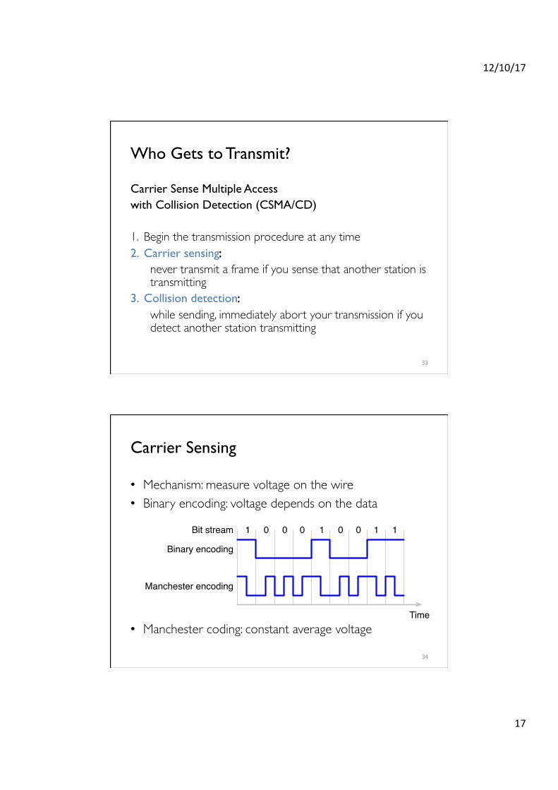
Carrier Sensing
• Mechanism: measure voltage on the wire• Binary encoding: voltage depends on the data
34
• Manchester coding: constant average voltageTime
1 0 0 0 1 11
Binary encoding
Manchester encoding
Bit stream 0 0
12/10/17
18
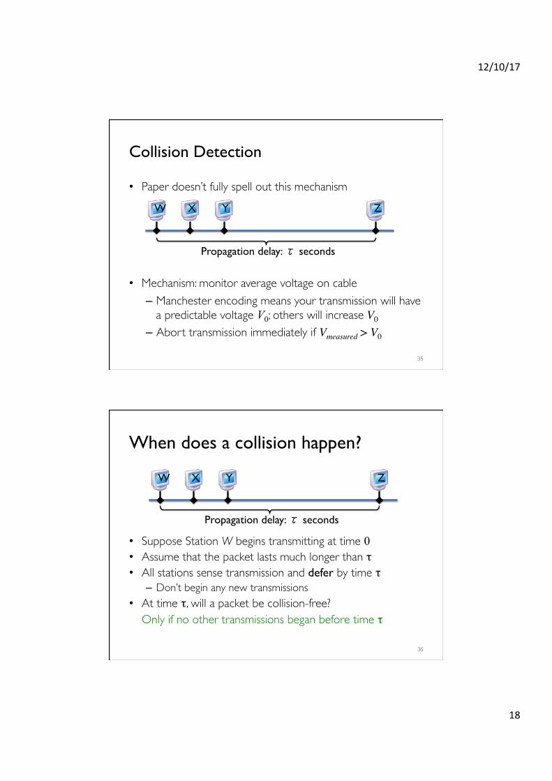
Collision Detection
• Paper doesn’t fully spell out this mechanism
• Mechanism: monitor average voltage on cable– Manchester encoding means your transmission will have
a predictable voltage V0; others will increase V0
– Abort transmission immediately if Vmeasured > V0
35
W X Y Z
Propagation delay: τ seconds
When does a collision happen?
• Suppose Station W begins transmitting at time 0 • Assume that the packet lasts much longer than τ• All stations sense transmission and defer by time τ– Don’t begin any new transmissions
• At time τ, will a packet be collision-free?Only if no other transmissions began before time τ
36
W X Y Z
Propagation delay: τ seconds
12/10/17
19
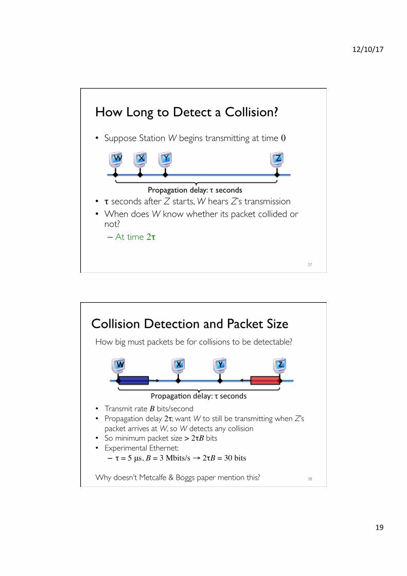
How Long to Detect a Collision?
• Suppose Station W begins transmitting at time 0
• τ seconds after Z starts, W hears Z’s transmission• When does W know whether its packet collided or
not? – At time 2τ
37
W X Y Z
Propagation delay: τ seconds
Collision Detection and Packet SizeHow big must packets be for collisions to be detectable?
• Transmit rate B bits/second• Propagation delay 2τ; want W to still be transmitting when Z’s
packet arrives at W, so W detects any collision• So minimum packet size > 2τB bits• Experimental Ethernet: – τ = 5 μs, B = 3 Mbits/s → 2τB = 30 bits
Why doesn’t Metcalfe & Boggs paper mention this? 38
W X Y Z
PropagaHondelay:τseconds
12/10/17
20
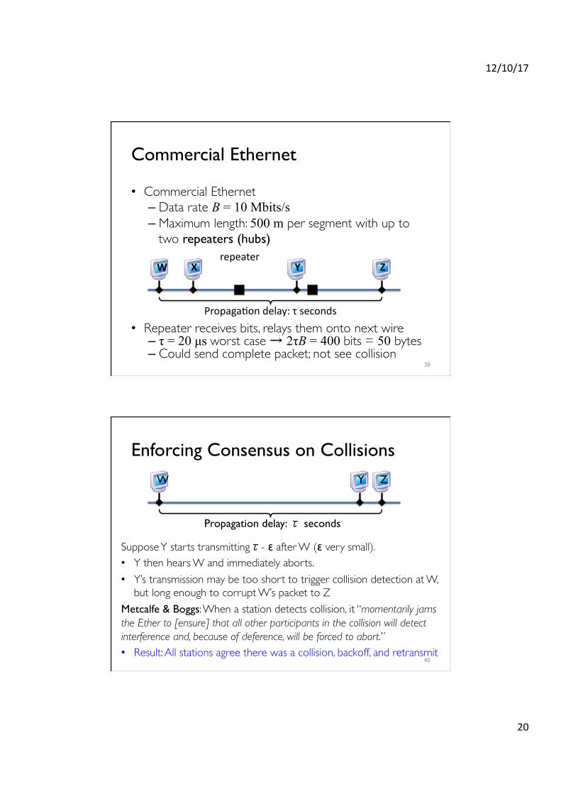
Commercial Ethernet
• Commercial Ethernet– Data rate B = 10 Mbits/s – Maximum length: 500 m per segment with up to
two repeaters (hubs)
• Repeater receives bits, relays them onto next wire– τ = 20 µs worst case → 2τB = 400 bits = 50 bytes– Could send complete packet; not see collision
39
W X Y Z
PropagaHondelay:τseconds
repeater
Enforcing Consensus on Collisions
Suppose Y starts transmittingτ- ε after W (ε very small).• Y then hears W and immediately aborts.• Y’s transmission may be too short to trigger collision detection at W,
but long enough to corrupt W’s packet to ZMetcalfe & Boggs: When a station detects collision, it “momentarily jams the Ether to [ensure] that all other participants in the collision will detect interference and, because of deference, will be forced to abort.”• Result: All stations agree there was a collision, backoff, and retransmit
40
W Z
Propagation delay: τ seconds
Y

12/10/17
21
Resolving Collisions
• Upon abort (carrier detect), a station enters the backoff state
• Key idea: the colliding stations all wait a random time before carrier sensing again and transmitting– How to pick the random waiting time? (Should be based
on how many stations have data to send)– How to estimate the number of colliding stations?
• Goal: Engineer such that nodes will wait different amounts of time, carrier sense again, and not collide
41
Slotted Ethernet Backoff
• Backoff time is slotted and random– Station’s view of the where the first slot begins is at the end of
the busy medium– Random choice of slots within a contention window (CW)
• Goal: Choose slot time so that different nodes picking different slots carrier sense and defer, thus don’t collide
42
Slot time
(CW)
Transmit
Contention Window
Busy Medium
12/10/17
22
OK Bad
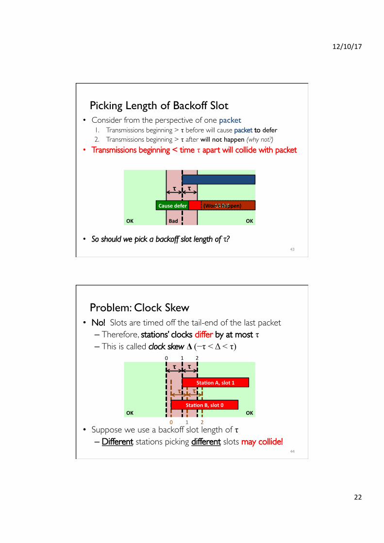
Picking Length of Backoff Slot• Consider from the perspective of one packet
1. Transmissions beginning > τ before will cause packet to defer 2. Transmissions beginning > τ after will not happen (why not?)
• Transmissions beginning < time τ apart will collide with packet
• So should we pick a backoff slot length of τ?43
OK
τ τ
Causedefer CSfail(Won’thappen)
OK
Problem: Clock Skew• No! Slots are timed off the tail-end of the last packet– Therefore, stations’ clocks differ by at most τ – This is called clock skew Δ (−τ < Δ < τ)
• Suppose we use a backoff slot length of τ – Different stations picking different slots may collide!
44
OK
τ τ
τ τΔ
Sta$onB,slot0
Sta$onA,slot1
0 1 2
0 1 2
12/10/17
23
OK
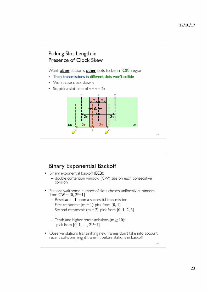
Picking Slot Length in�Presence of Clock Skew
Want other station’s other slots to be in “OK” region• Then, transmissions in different slots won’t collide• Worst case clock skew: τ • So, pick a slot time of τ + τ = 2τ
45
OK
τ τ
2τ2τ
Δ
2τ2τ
0 1 2
0 1 2
Binary Exponential Backoff• Binary exponential backoff (BEB): – double contention window (CW) size on each consecutive
collision
• Stations wait some number of slots chosen uniformly at random from CW = [0, 2m−1] – Reset m ← 1 upon a successful transmission– First retransmit (m = 1): pick from [0, 1] – Second retransmit (m = 2): pick from [0, 1, 2, 3] – …– Tenth and higher retransmissions (m ≥ 10):
pick from [0, 1, …, 210−1]
• Observe: stations transmitting new frames don’t take into account recent collisions, might transmit before stations in backoff
46
12/10/17
24
Next time: Wireless LANs and WiFi
51
Recommended