MICRO SWITCH™ Hermetic Sealed Basic SwitchesHM Series
Datasheet
2 sensing.honeywell.com
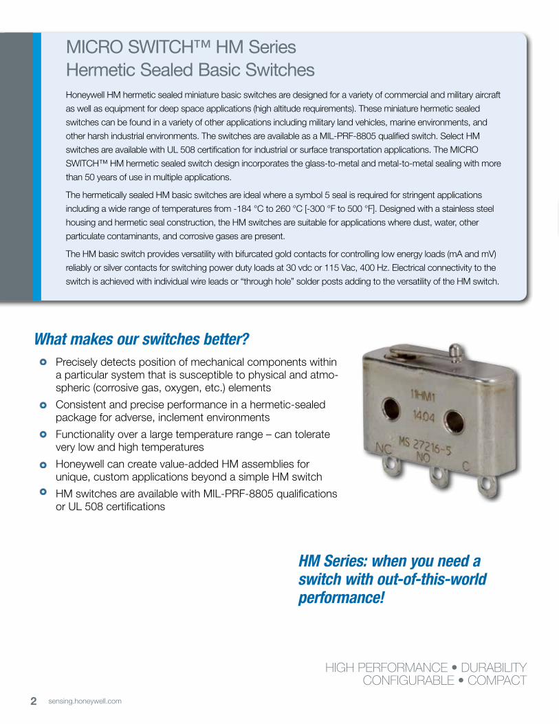
What makes our switches better? Precisely detects position of mechanical components within
a particular system that is susceptible to physical and atmo-spheric (corrosive gas, oxygen, etc.) elements
Consistent and precise performance in a hermetic-sealed package for adverse, inclement environments
Functionality over a large temperature range – can tolerate very low and high temperatures
Honeywell can create value-added HM assemblies for unique, custom applications beyond a simple HM switch
HM switches are available with MIL-PRF-8805 qualifications or UL 508 certifications
MICRO SWITCH™ HM Series Hermetic Sealed Basic SwitchesHoneywell HM hermetic sealed miniature basic switches are designed for a variety of commercial and military aircraft
as well as equipment for deep space applications (high altitude requirements). These miniature hermetic sealed
switches can be found in a variety of other applications including military land vehicles, marine environments, and
other harsh industrial environments. The switches are available as a MIL-PRF-8805 qualified switch. Select HM
switches are available with UL 508 certification for industrial or surface transportation applications. The MICRO
SWITCH™ HM hermetic sealed switch design incorporates the glass-to-metal and metal-to-metal sealing with more
than 50 years of use in multiple applications.
The hermetically sealed HM basic switches are ideal where a symbol 5 seal is required for stringent applications
including a wide range of temperatures from -184 °C to 260 °C [-300 °F to 500 °F]. Designed with a stainless steel
housing and hermetic seal construction, the HM switches are suitable for applications where dust, water, other
particulate contaminants, and corrosive gases are present.
The HM basic switch provides versatility with bifurcated gold contacts for controlling low energy loads (mA and mV)
reliably or silver contacts for switching power duty loads at 30 vdc or 115 Vac, 400 Hz. Electrical connectivity to the
switch is achieved with individual wire leads or “through hole” solder posts adding to the versatility of the HM switch.
HIGH PERFORMANCE • DURABILITYCONFIGURABLE • COMPACT
HM Series: when you need a switch with out-of-this-world performance!

3sensing.honeywell.com
Features and Benefits Features and Benefits
MIL-QUALIFIEDMICRO SWITCH™ HM switches are hermetically sealed with versions that are MIL-PRF-8805 qualified for demanding military or commercial applications on aircraft, spacecraft, or ground vehicles.
UL CERTIFIEDSelect HM catalog listings are UL 508 certified for industrial and surface transportation applications.
TINY Miniature package size requires minimal space on equipment.
SEALED TIGHT HM Series’ Symbol 5 hermetic-sealed enclosures are suitable for applications at sea level, high altitude, or deep space.
LOW VOLTAGE AND POWER DUTY CAPABILITY MICRO SWITCH™ HM products are available with silver contacts for control of power duty circuits or gold contact surfaces for control of logic level circuits.
LEVERS FURTHER EXPAND FUNCTIONALITY Auxiliary actuators expand the versatility of the switch for additional applications.
WELL SUITED FOR LOW AND HIGH TEMPERATURES For endurance in harsh temperature environments, wide temperature range is available from -184 °C to 260 °C [-300 °F to 500 °F]. Operate point stability is maintained over the specified temperature range.
Hermetically sealed with wide temperature range

4 sensing.honeywell.com
MILITARY AIRCRAFT AND HELICOPTERS• Detects landing gear bay doors in closed and locked position• Senses engine fuel valve position• Identifies when external hatches and doors are in closed and/or locked position
COMMERCIAL AIRCRAFT AND HELICOPTERS• Detects landing gear bay doors in closed and locked position• Senses engine fuel valve position• Identifies when external hatches and doors are in closed and/or locked position• Miscellaneous applications inside commercial aircraft cabin, including waste
management valve position, refreshment (liquids and food) stowed and locked position, HVAC, and oxygen valve position
AVIATION GROUND SUPPORT EQUIPMENT
• Monitor position of valves, doors or panels, for open, closed, or locked position
SPACECRAFT• Identifies when external hatches and doors are in closed and/or locked position• Senses engine fuel valve position• Select sensing applications inside spacecraft cabin
POWER GENERATION, OIL AND GAS• Internal switch element in pressure switches, temperature switches, and/or flow
switches
Potential Applications

5sensing.honeywell.com
MICRO SWITCH™ Hermetic Sealed Basic Switches
Table 1. Specifications
Characteristic
Description hermetic sealed miniature snap-action switch
Housing material 300 series stainless steel
Mechanical endurance 25,000 operations min.
Electrical endurance 25,000 operations min.
Dielectric voltage (initial) 1000 Vrms for 1 minute
Circuitry SPDT
Contact material silver, gold, gold bifurcated
Electrical rating up to 4 A at 28 Vdc (ref. electrical rating table)
Sealing symbol 5, hermetic sealed to MIL-PRF-8805
Temperature range -65 °C to 121 °C [-85 °F to 250 °F] (see catalog listing table)
Temperature range (optional) -184 °C to 260 °C [-300 °F to 500 °F] (see catalog listing table)
Vibration symbol 2 (15 g), 10 to 2000 Hz
Mechanical shock shock type M (100 G, saw tooth)
Approvals (refer to page 7) MIL-PRF-8805, UL 508 (File E66520)
Actuators (auxiliary) straight leaf, roller leaf, straight lever, roller lever
Table 2. Electrical Ratings
Rating code
Asea level @ 28 Vdc; 3 A res. and 1 A ind.
70,000 feet @ 28 Vdc; 3 A res. and 1 A ind. sea level @ 115 Vac & 400 Hz; 1 A res. and 1 A ind.
Bsea level @ 28 Vdc; 1 A res. and 0.25 A ind.
70,000 feet @ 28 Vdc; 1 A res. and 0.25 A ind.
Csea level @ 28 Vdc; 0.5 A res. and 0.25 A ind.
70,000 feet @ 28 Vdc; 0.5 A res. and 0.25 A ind.
Dsea level @ 28 Vdc; 4 A res., 2 A ind. and 1 A lamp
70,000 feet @ 28 Vdc; 4 A res., 2 A ind. and 1 A lamp sea level @ 115 Vac & 400 Hz; 2 A res., 2 A ind. and 0.5 A lamp
Esea level @ 28 Vdc; 4 res. and 2 A ind.
sea level @ 115 Vac and 400 Hz; 2.5 A res. and 2.5 A ind.
Table 3. UL 508 Electrical Ratings
Rating code
F 28 Vdc, 0.5 A res.; -65 °C to 125 °C [-85 °F to 257 °F]
G 28 Vdc, 3 A res.; -65 °C to 125 °C [-85 °F to 257 °F]
H 28 Vdc, 0.5 A res.; -65 °C to 260 °C [-85 °F to 500 °F]
J 28 Vdc, 4 A res.; -65 °C to 260 °C [-85 °F to 500 °F]

6 sensing.honeywell.com
HM Series
ELECTROMECHANICAL SWITCHES
Definitions below explain the meaning of operating characteristics. Characteristics shown in tables were chosen as most significant. They are taken at normal room temperature and humidity. These may vary as temperature and humidity conditions differ. Sketches show how characteristics are measured for in-line plunger actuation.
Linear dimensions for in-line actuation are from top of plunger to a reference line, usually the center of the mounting holes.
Differential Travel (D.T.) – Plunger or actuator travel from point where contacts ‘‘snap-over’’ to point where they ‘‘snap-back.’’
Free Position (F.P.) – Position of switch plunger or actuator when no external force is applied (other than gravity).
Full Overtravel Force – Force required to attain full overtravel of actuator.
Operating Position (O.P.) – Position of switch plunger or actuator at which point contacts snap from normal to operated position. Note that in the case of flexible or adjustable actuators, the operating position is measured from the end of the lever or its maximum length. Location of operating position measurement shown on mounting dimension drawings.
Operating Force (O.F.) – Amount of force applied to switch plunger or actuator to cause contact ‘‘snap-over.’’ Note in the case of adjustable actuators, the force is measured from the maximum length posi-tion of the lever.
Overtravel (O.T.) – Plunger or actuator travel safely available beyond operating position.
Pretravel (P.T.) – Distance or angle trav-eled in moving plunger or actuator from free position to operating position.
Release Force (R.F.) – Amount of force still applied to switch plunger or actuator at moment contacts snap from operated position to unoperated position.
Total Travel (T.T.) – Distance from actuator free position to overtravel limit position.
7sensing.honeywell.com
MICRO SWITCH™ Hermetic Sealed Basic Switches O.F. • Operating forceR.F. • Release forceP.T. • PretravelO.T. • OvertravelD.T. • Differential travelO.P. • Operating position
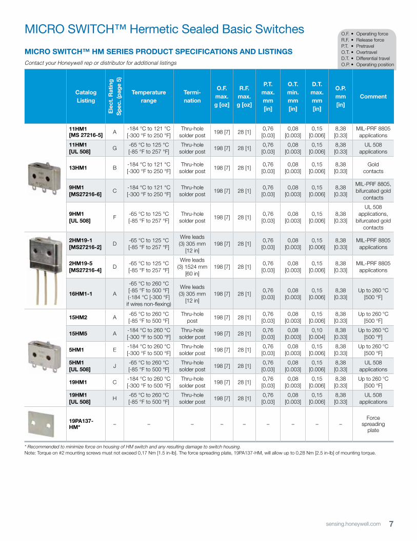
MICRO SWITCH™ HM SERIES PRODUCT SPECIFICATIONS AND LISTINGSContact your Honeywell rep or distributor for additional listings
Catalog Listing
Ele
ct. R
atin
g
Sp
ec. (
pag
e 5)
Temperature range
Termi-nation
O.F. max.g [oz]
R.F. max.g [oz]
P.T. max. mm [in]
O.T. min. mm [in]
D.T. max. mm [in]
O.P.mm [in]
Comment
11HM1 [MS 27216-5] A
-184 °C to 121 °C [-300 °F to 250 °F]
Thru-hole solder post
198 [7] 28 [1]0,76 [0.03]
0,08 [0.003]
0,15 [0.006]
8,38 [0.33]
MIL-PRF 8805 applications
11HM1[UL 508]
G-65 °C to 125 °C [-85 °F to 257 °F]
Thru-hole solder post
198 [7] 28 [1]0,76 [0.03]
0,08 [0.003]
0,15 [0.006]
8,38 [0.33]
UL 508 applications
13HM1 B-184 °C to 121 °C [-300 °F to 250 °F]
Thru-hole solder post
198 [7] 28 [1]0,76 [0.03]
0,08 [0.003]
0,15 [0.006]
8,38 [0.33]
Gold contacts
9HM1 [MS27216-6]
C-184 °C to 121 °C [-300 °F to 250 °F]
Thru-hole solder post
198 [7] 28 [1]0,76 [0.03]
0,08 [0.003]
0,15 [0.006]
8,38 [0.33]
MIL-PRF 8805, bifurcated gold
contacts
9HM1 [UL 508]
F-65 °C to 125 °C [-85 °F to 257 °F]
Thru-hole solder post
198 [7] 28 [1]0,76 [0.03]
0,08 [0.003]
0,15 [0.006]
8,38 [0.33]
UL 508 applications,
bifurcated gold contacts
2HM19-1 [MS27216-2]
D-65 °C to 125 °C [-85 °F to 257 °F]
Wire leads (3) 305 mm
[12 in]198 [7] 28 [1]
0,76 [0.03]
0,08 [0.003]
0,15 [0.006]
8,38 [0.33]
MIL-PRF 8805 applications
2HM19-5 [MS27216-4]
D-65 °C to 125 °C [-85 °F to 257 °F]
Wire leads (3) 1524 mm
[60 in]198 [7] 28 [1]
0,76 [0.03]
0,08 [0.003]
0,15 [0.006]
8,38 [0.33]
MIL-PRF 8805 applications
16HM1-1 A
-65 °C to 260 °C [-85 °F to 500 °F] (-184 °C [-300 °F] if wires non-flexing)
Wire leads (3) 305 mm
[12 in]198 [7] 28 [1]
0,76 [0.03]
0,08 [0.003]
0,15 [0.006]
8,38 [0.33]
Up to 260 °C [500 °F]
15HM2 A-65 °C to 260 °C [-85 °F to 500 °F]
Thru-hole post
198 [7] 28 [1]0,76 [0.03]
0,08 [0.003]
0,15 [0.006]
8,38 [0.33]
Up to 260 °C [500 °F]
15HM5 A-184 °C to 260 °C [-300 °F to 500 °F]
Thru-hole solder post
198 [7] 28 [1]0,76 [0.03]
0,08 [0.003]
0,10[0.004]
8,38 [0.33]
Up to 260 °C [500 °F]
5HM1 E-184 °C to 260 °C [-300 °F to 500 °F]
Thru-hole solder post
198 [7] 28 [1]0,76 [0.03]
0,08 [0.003]
0,15[0.006]
8,38 [0.33]
Up to 260 °C [500 °F]
5HM1[UL 508]
J-65 °C to 260 °C [-85 °F to 500 °F]
Thru-hole solder post
198 [7] 28 [1]0,76 [0.03]
0,08 [0.003]
0,15[0.006]
8,38 [0.33]
UL 508 applications
19HM1 C-184 °C to 260 °C [-300 °F to 500 °F]
Thru-hole solder post
198 [7] 28 [1]0,76 [0.03]
0,08 [0.003]
0,15[0.006]
8,38 [0.33]
Up to 260 °C [500 °F]
19HM1[UL 508]
H-65 °C to 260 °C [-85 °F to 500 °F]
Thru-hole solder post
198 [7] 28 [1]0,76 [0.03]
0,08 [0.003]
0,15[0.006]
8,38 [0.33]
UL 508 applications
19PA137-HM* – – – – – – – – –
Forcespreading
plate
* Recommended to minimize force on housing of HM switch and any resulting damage to switch housing.Note: Torque on #2 mounting screws must not exceed 0,17 Nm [1.5 in-lb]. The force spreading plate, 19PA137-HM, will allow up to 0,28 Nm [2.5 in-lb] of mounting torque.

8 sensing.honeywell.com
HM SeriesJS SERIES LEVERS SPECIFICATIONS* (WHEN ASSEMBLED TO 16HM1-1)
Description
Actuator
Length
mm [in]
Operating
Force
max.
g [oz]
Release
Force min.
g [oz]
Pretravel
nom.
mm [in]
Overtravel
min.
mm [in]
Differential
Travel max.
mm [in]
Operating
Point
nom.
mm [in]
Free
Position
nom.
mm [in]
JS-2
54
Straight leaf 8,13 [0.32] 255 [9] 57 [2]3,56 [0.14]
0,76 [0.03]
0,76 [0.03]
8,64 [0.34]
12,2 [0.48]
JS-1
51 Roller leaf(mounting hardware
included)8,13 [0.32] 255 [9] 57 [2]
3,56 [0.14]
0,76 [0.03]
0,76 [0.03]
14 [0.55]
17,5[0.69]
JS-3
07 Straight lever(mounting hardware
included)
26,16 [1.03]
43 [1.5] 3 [0.11]3,18
[0.125]0,64
[0.025]1,42
[0.056]10,3
[0.406]13,49[0.531]
JS-3
08 Roller lever(mounting hardware
included)
25,4 [1.00] radius
43 [1.5] 3 [0.11]3,18
[0.125]0,64
[0.025]1,42
[0.056]14,3
[0.562]17,45[0.687]
* Stainless steel actuators, including roller and mounting hardware (when provided).
9sensing.honeywell.com
MICRO SWITCH™ Hermetic Sealed Basic Switches
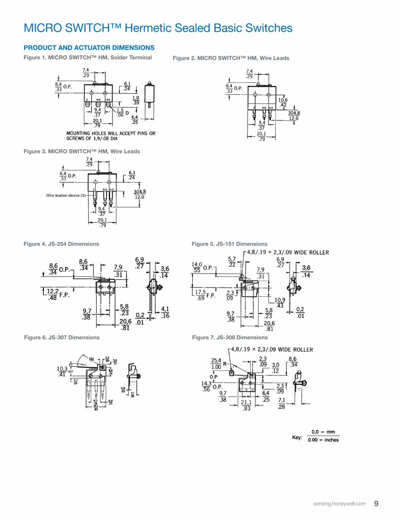
PRODUCT AND ACTUATOR DIMENSIONSFigure 1. MICRO SWITCH™ HM, Solder Terminal Figure 2. MICRO SWITCH™ HM, Wire Leads
Figure 3. MICRO SWITCH™ HM, Wire Leads
Figure 4. JS-254 Dimensions Figure 5. JS-151 Dimensions
Figure 6. JS-307 Dimensions Figure 7. JS-308 Dimensions
10 sensing.honeywell.com
HM Series
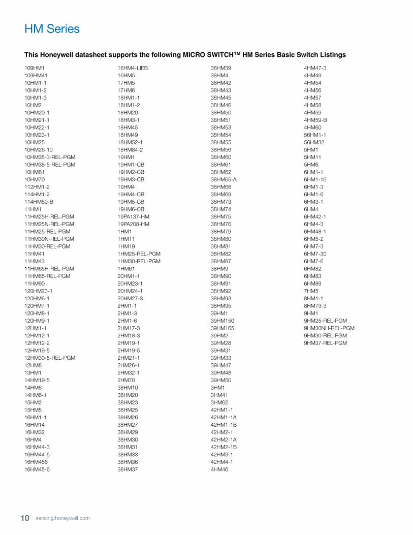
This Honeywell datasheet supports the following MICRO SWITCH™ HM Series Basic Switch Listings
109HM1109HM4110HM1-110HM1-210HM1-310HM210HM20-110HM21-110HM22-110HM23-110HM2510HM26-1010HM35-3-REL-PGM10HM38-5-REL-PGM10HM6110HM70112HM1-2114HM1-2114HM59-B11HM111HM25H-REL-PGM11HM25N-REL-PGM11HM25-REL-PGM11HM30N-REL-PGM11HM30-REL-PGM11HM4111HM4311HM65H-REL-PGM11HM65-REL-PGM11HM90120HM23-1120HM6-1120HM7-1120HM8-1120HM9-112HM1-112HM12-112HM12-212HM19-512HM30-5-REL-PGM12HM813HM114HM19-514HM614HM6-115HM215HM516HM1-116HM1416HM3216HM416HM44-316HM44-616HM45616HM45-6
16HM4-LIEB16HM517HM517HM618HM1-118HM1-218HM2018HM3-118HM4518HM4918HM52-118HM84-219HM119HM1-CB19HM2-CB19HM3-CB19HM419HM4-CB19HM5-CB19HM6-CB19PA137-HM19PA208-HM1HM11HM111HM191HM25-REL-PGM1HM30-REL-PGM1HM6120HM1-120HM23-120HM24-120HM27-32HM1-12HM1-32HM1-62HM17-32HM18-32HM19-12HM19-52HM21-12HM26-12HM32-12HM7038HM1038HM2038HM2338HM2538HM2638HM2738HM2938HM3038HM3138HM3338HM3638HM37
38HM3938HM438HM4238HM4338HM4538HM4638HM5038HM5138HM5338HM5438HM5538HM5638HM6038HM6138HM6238HM65-A38HM6838HM6938HM7338HM7438HM7538HM7638HM7938HM8038HM8138HM8238HM8738HM938HM9038HM9138HM9238HM9338HM9539HM139HM15039HM16539HM239HM2839HM3139HM3339HM4739HM4839HM503HM13HM413HM6242HM1-142HM1-1A42HM1-1B42HM2-142HM2-1A42HM2-1B42HM3-142HM4-14HM46
4HM47-34HM494HM544HM564HM574HM584HM594HM59-B4HM6056HM1-156HM325HM15HM115HM66HM1-16HM1-166HM1-36HM1-66HM3-16HM46HM42-16HM4-36HM48-16HM5-26HM7-36HM7-306HM7-66HM826HM836HM897HM58HM1-18HM73-39HM19HM25-REL-PGM9HM30NH-REL-PGM9HM30-REL-PGM9HM37-REL-PGM
11sensing.honeywell.com
MICRO SWITCH™ Hermetic Sealed Basic Switches
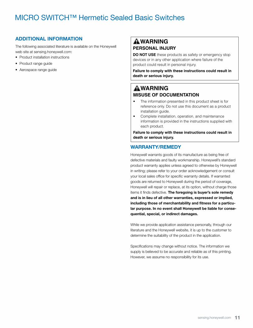
ADDITIONAL INFORMATIONThe following associated literature is available on the Honeywell web site at sensing.honeywell.com:• Product installation instructions
• Product range guide
• Aerospace range guide
WARNINGPERSONAL INJURYDO NOT USE these products as safety or emergency stop devices or in any other application where failure of the product could result in personal injury.
Failure to comply with these instructions could result in death or serious injury.
WARNINGMISUSE OF DOCUMENTATION• The information presented in this product sheet is for
reference only. Do not use this document as a product installation guide.
• Complete installation, operation, and maintenance information is provided in the instructions supplied with each product.
Failure to comply with these instructions could result in death or serious injury.
WARRANTY/REMEDYHoneywell warrants goods of its manufacture as being free of defective materials and faulty workmanship. Honeywell’s standard product warranty applies unless agreed to otherwise by Honeywell in writing; please refer to your order acknowledgement or consult your local sales office for specific warranty details. If warranted goods are returned to Honeywell during the period of coverage, Honeywell will repair or replace, at its option, without charge those items it finds defective. The foregoing is buyer’s sole remedy and is in lieu of all other warranties, expressed or implied, including those of merchantability and fitness for a particu-lar purpose. In no event shall Honeywell be liable for conse-quential, special, or indirect damages.
While we provide application assistance personally, through our literature and the Honeywell website, it is up to the customer to determine the suitability of the product in the application.
Specifications may change without notice. The information we supply is believed to be accurate and reliable as of this printing. However, we assume no responsibility for its use.
003123-1-EN IL50 GLO March 2015Copyright © 2015 Honeywell International Inc. All rights reserved.
Sensing and Control
Honeywell
1985 Douglas Drive North
Golden Valley, MN 55422
honeywell.com
Find out moreHoneywell serves its customers through a worldwide network of sales offices, representatives and distributors. For application assistance, current specifications, pricing or name of the nearest Authorized Distributor, contact your local sales office.
To learn more about Honeywell’s
sensing and control products,
call +1-815-235-6847 or
1-800-537-6945,
visit sensing.honeywell.com,
or e-mail inquiries to
Recommended