11
Minnesota Local Road Research
Board
Training Module for Designing and
Constructing with Geosynthetics

33
Who Are We?
• You are…
• What do you want to learn today?
44
General order of the day
• Introduction
• History of Geosynthetics
• Geosynthetics Available in the Marketplace
• Geosynthetic Product Properties
• Geosynthetics in Roads
• Geosynthetics in Grade Separation Structures
55
What this class is about
• What are the PRODUCTS
• PLANNING to use geosynthetics in Highwayprojects
• DESIGN of geosynthetics beneath road subgradesand for grade separation structures
• INSTALLATION and INSPECTION ofgeosynthetics beneath roads and for grade separationstructures
66
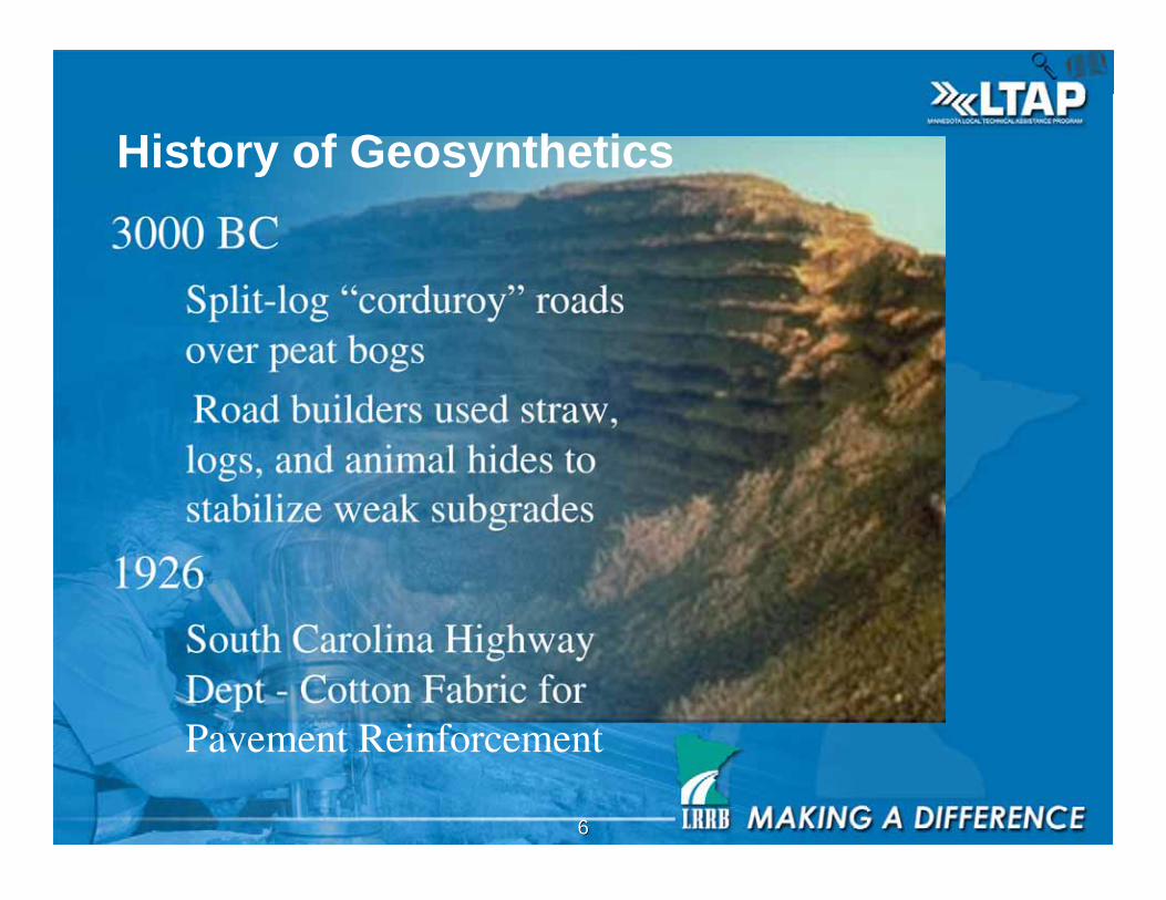
3000 BC Split-log “corduroy” roads
over peat bogs
Road builders used straw,logs, and animal hides tostabilize weak subgrades
1926 South Carolina Highway
Dept - Cotton Fabric forPavement Reinforcement
History of Geosynthetics
77
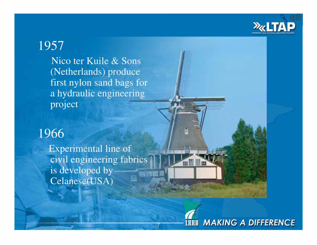
1957 Nico ter Kuile & Sons
(Netherlands) producefirst nylon sand bags fora hydraulic engineeringproject
1966 Experimental line of
civil engineering fabricsis developed byCelanese(USA)
88
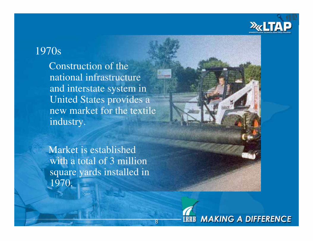
1970s Construction of the
national infrastructureand interstate system inUnited States provides anew market for the textileindustry.
Market is establishedwith a total of 3 millionsquare yards installed in1970.
99
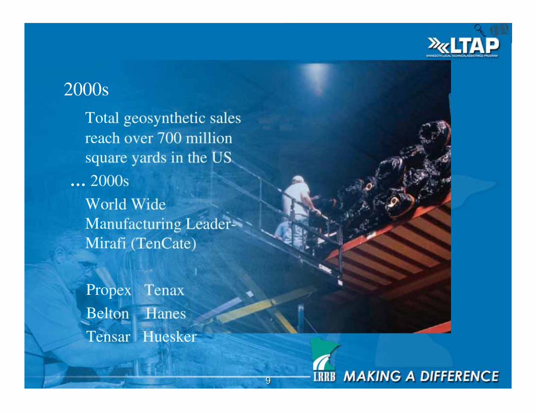
2000s
Total geosynthetic salesreach over 700 millionsquare yards in the US
… 2000s
World WideManufacturing Leader-Mirafi (TenCate)
Propex Tenax
Belton Hanes
Tensar Huesker

1010
Class Participation
• When did you first use a geosynthetic product?
• Where did you get the information you needed
to use it?
• What product do you use the most?

1111
Acknowledgments
• The following firms provided slides/photos for
this course
• Geosynthetic Institute
• TenCate Geosynthetics (Mirafi)
• Tenax Corporation
• Mn/DOT Geotechnologies
• Gale-Tec Engineering, Inc.
1212
Sources of Information
• Geosynthetic Engineering by Holtz, Christopher and
Berg
• Designing with Geosynthetics by Koerner
• Geosynthetic Design and Construction Guidelines,
participant notebook, NHI Course No. 13213, US
Department of Transportation, Publication No.
FHWA HI-95-038. Update published 2007
• Gale-Tec Engineering, Inc. Project Files
• MnDOT Project Files

1313
More Sources of Information
• Contact Mn/DOT’s Office of Materials for
most recent information on specifications and
approved products.
• Phone: (651) 366-5592
• http://www.mrr.dot.state.mn.us/materials/mate
rials.asp

1414
If nothing else, we want you to learn…
• PLANNING: there are cost and performancebenefits to using these materials.
• DESIGNING: some projects can be specifiedbased on experience and empirical data whileothers need to be designed by a licensedprofessional engineer trained ingeotechnical/geosynthetic engineering
• INSTALLING: with training, these productscan be installed successfully.

1515
What are these things we call
geosynthetics?
From Koerner, 1994, page 2:
Geosynthetic – a planar product manufactured
from polymeric material used with soil, rock,
earth, or other geotechnical engineering related
material as an integral part of a man-made
project, structure, or system.
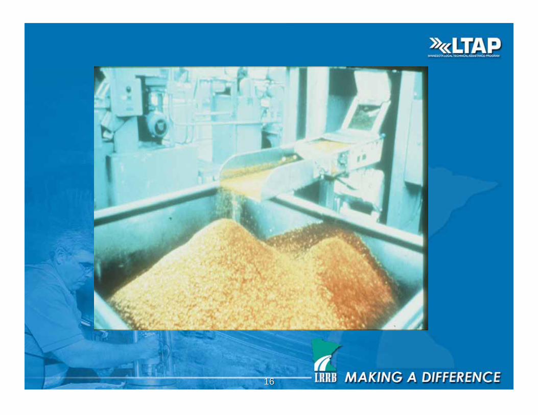
1616
1717
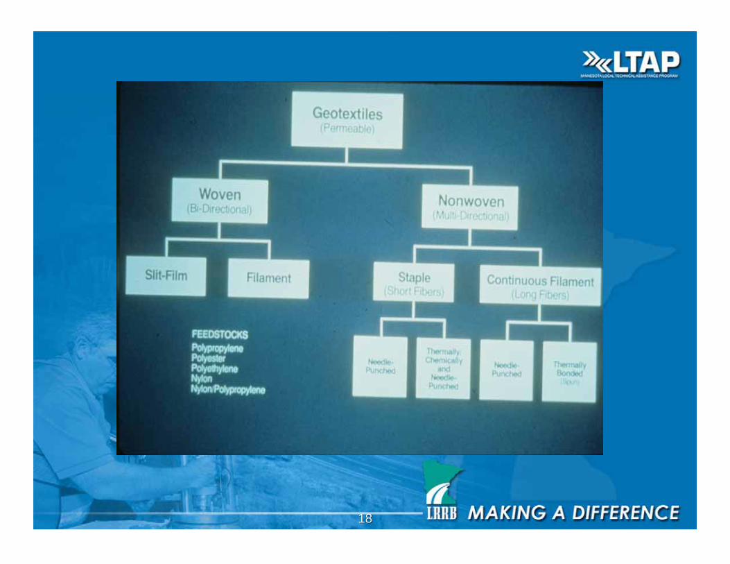
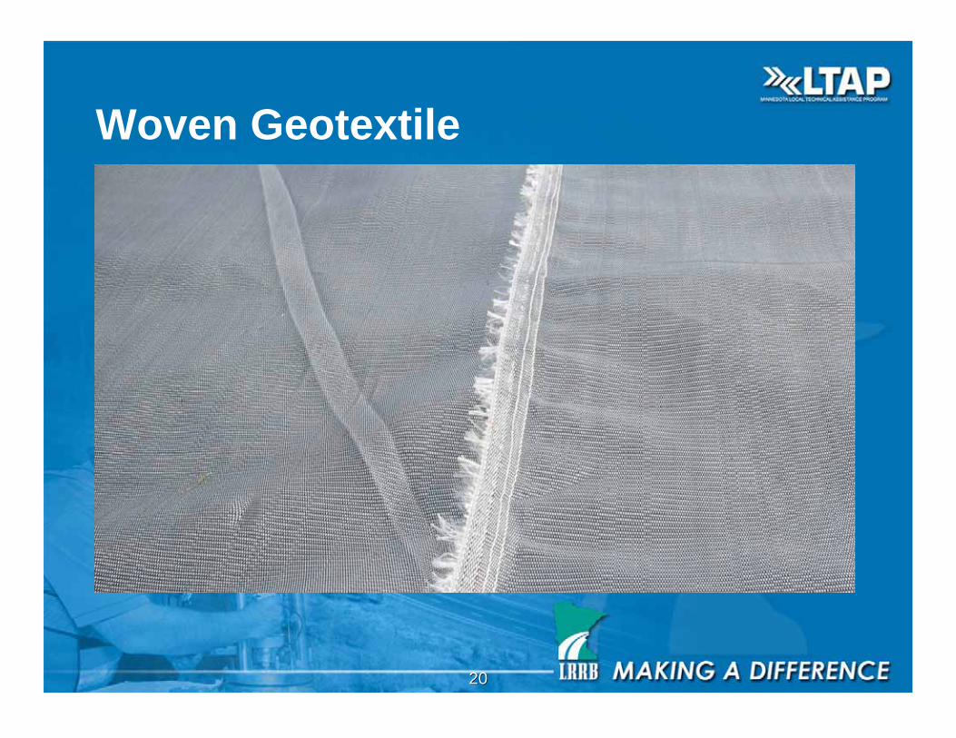
Geotextiles• Permeable geosynthetic made of polypropylene or
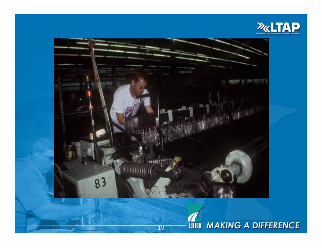
polyester resin– Woven geotextiles are composed of either single or bundles
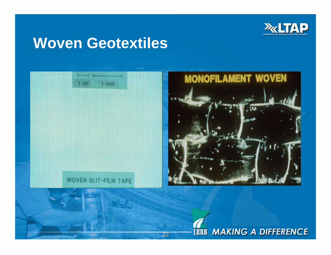
of yarns woven together by a loom• Monofilaments are round
• Slit films are flat
– Non-Woven geotextiles are random laid fibers that areneedle punched or heated
• Used for separation, reinforcement, filtration, anddrainage (Trampolines, car trunk liners, furniturebacking, carpet backing, temporary covers forlandfills)
1818
1919
2020
Woven Geotextile
2121
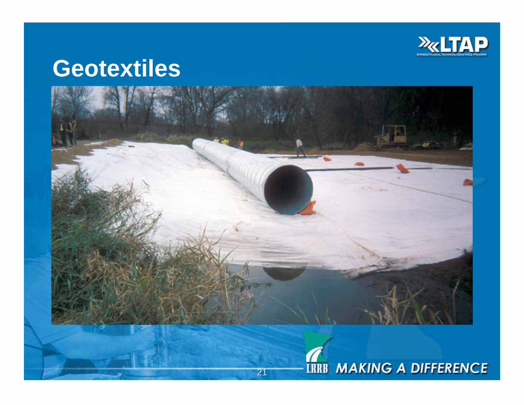
Geotextiles
2222
Woven Geotextiles
2323
Geogrids
• Open grid-like structures, made of extrudedpolypropylene (U.S. patent), rubber coatedpolypropylene, PVC coated polyester, highdensity polyethylene, and laser weldedpolyester straps
• Used for reinforcement, aggregate interlock(snow fence, conveyor belts, mine and rockexcavation covering, fish farming retentiongrids)
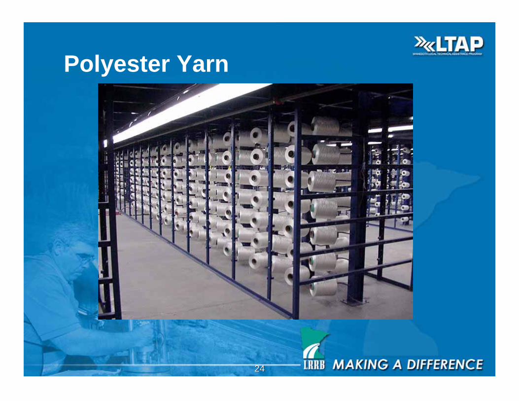
2424
Polyester Yarn
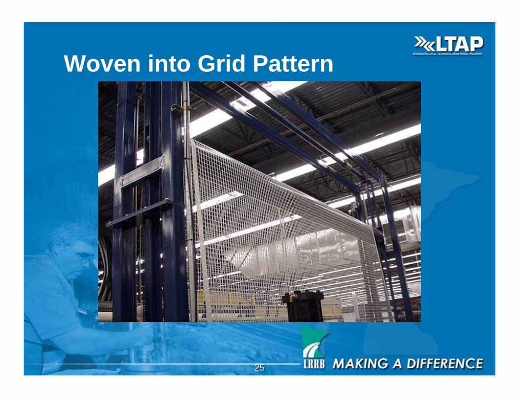
2525
Woven into Grid Pattern
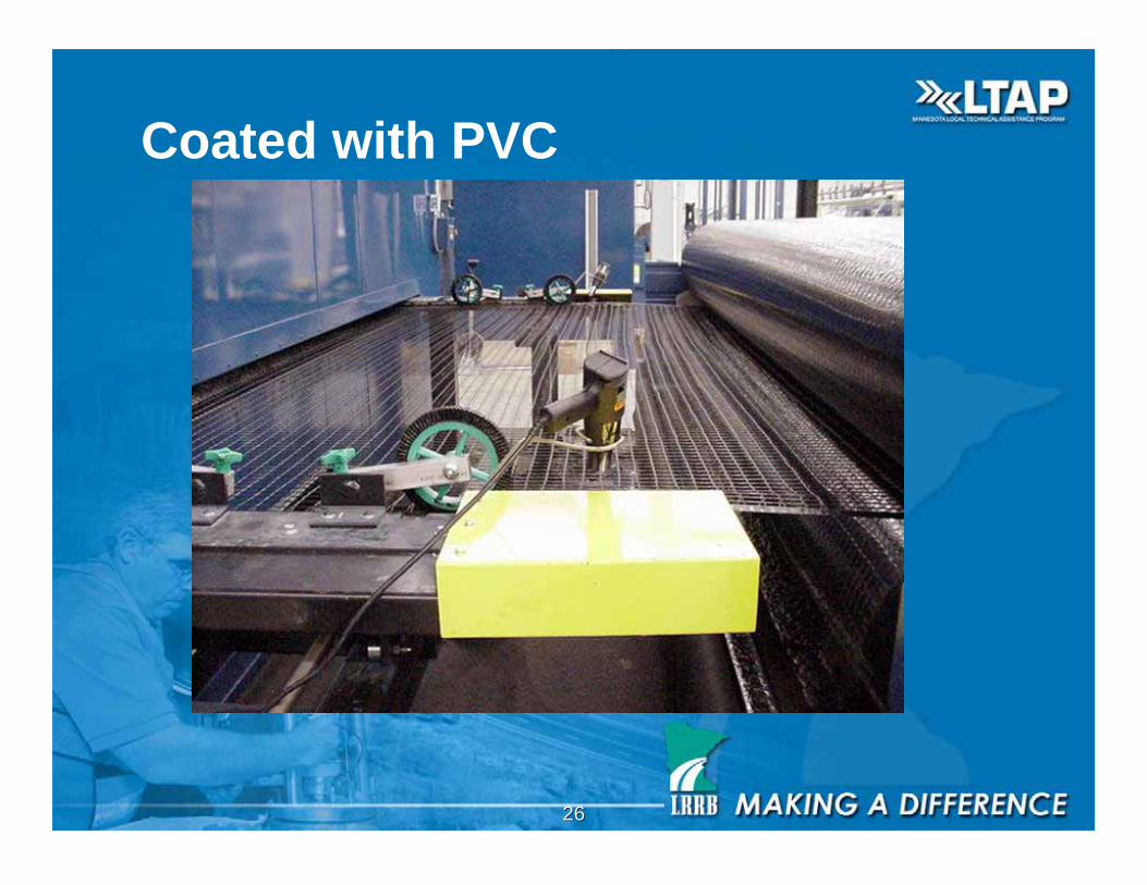
2626
Coated with PVC

2727
Tri-Packing Rolls
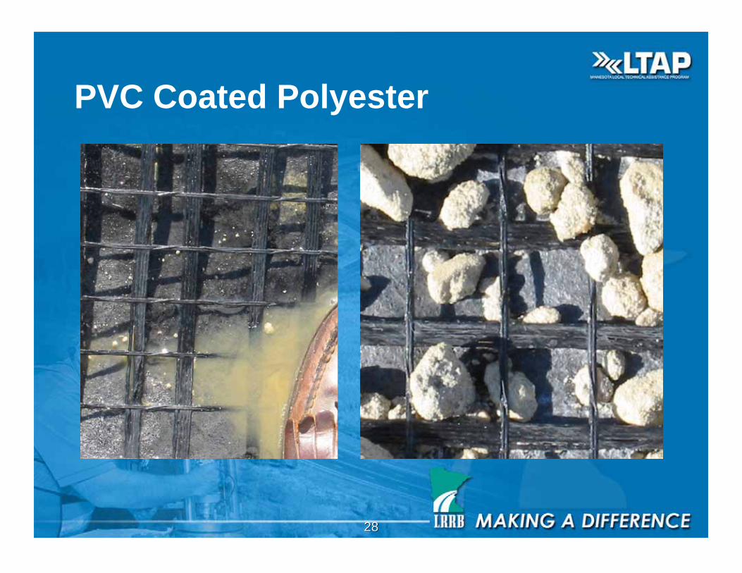
2828
PVC Coated Polyester
2929
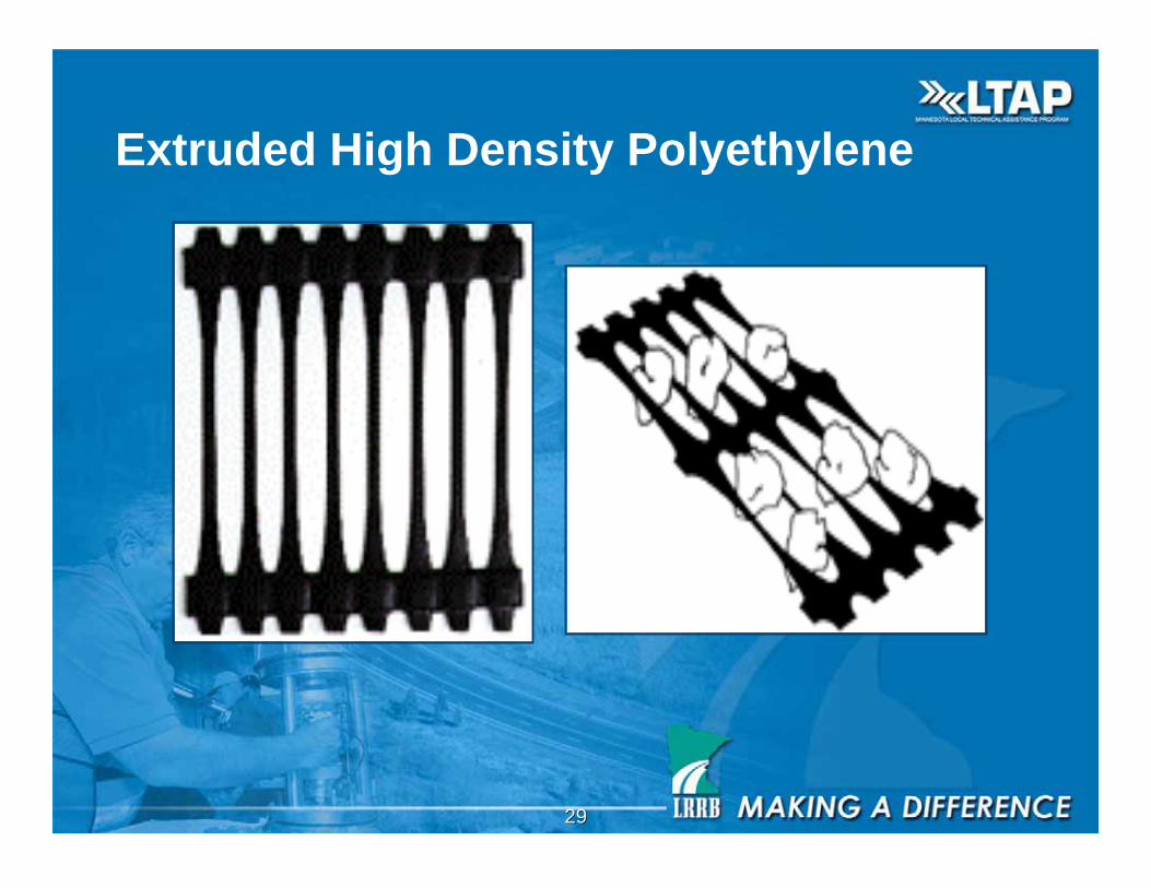
Extruded High Density Polyethylene
3030
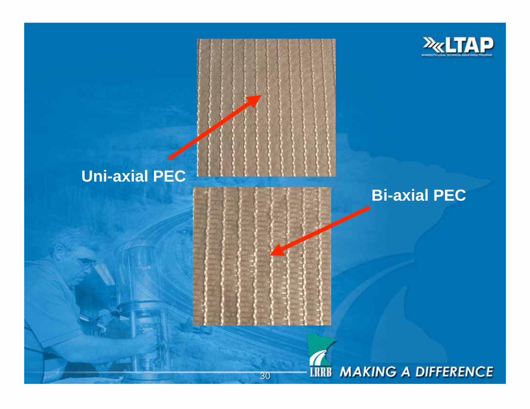
Uni-axial PEC
Bi-axial PEC
3131
Geofoam
• Expanded Polystyrene
• Unit Weights between 1-3 pounds per cubic
foot.
• Soil Unit Weight between 120-140 pounds per
cubic foot
• Cost is $35-$45/cubic yard (1ft. thick x 4 ft x8
ft. piece costs $50
3232
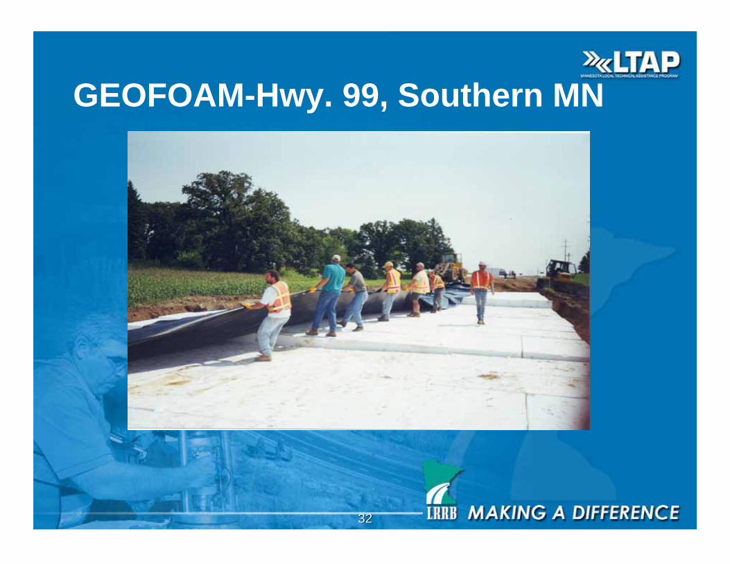
GEOFOAM-Hwy. 99, Southern MN
3333
3434
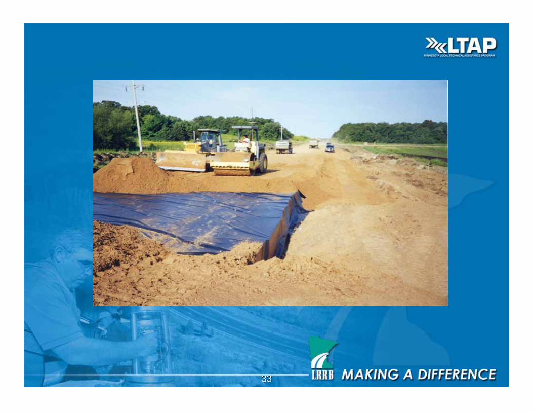
Geomembranes
• Impervious sheets of High Density
Polyethylene, Linear Low Density
Polyethylene, Poly Vinyl Chloride,
• Used to contain fluids
• Roads over MSE walls with metal
reinforcement require a liner to reduce salt
infiltration
3535
Geosynthetic Clay Liners (GCL)
• Composed of a layer of bentonite sandwiched
between layers of geotextiles.
• Serve as a hydraulic barrier.

3636
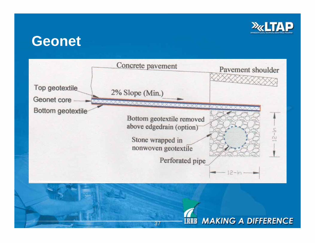
Geonet and Other Composites
• Composed of a three dimensional structure of
high density polyethylene sandwiched between
one or two layers of needle punched
Nonwoven or monofilament geotextiles
3737
Geonet
3838
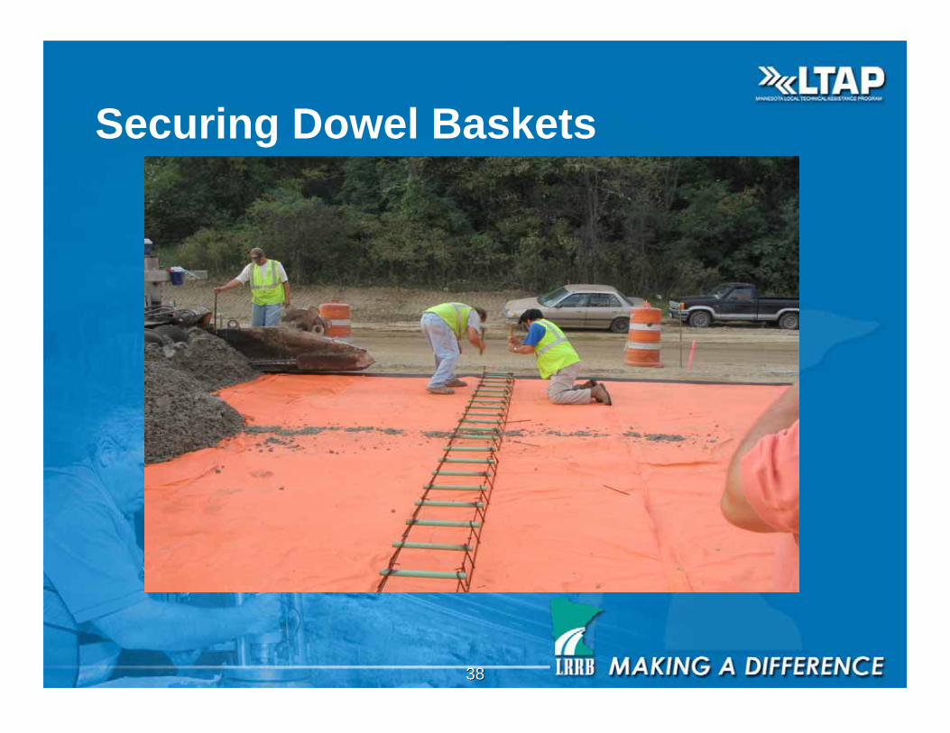
Securing Dowel Baskets
3939
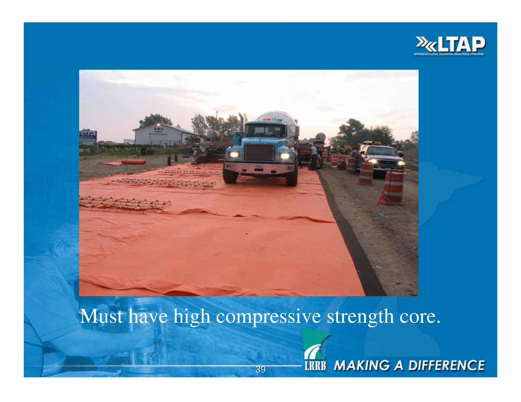
Must have high compressive strength core.

4040
Concrete Paver Tracks on Roadrain

4141
Curb & Gutter
4242
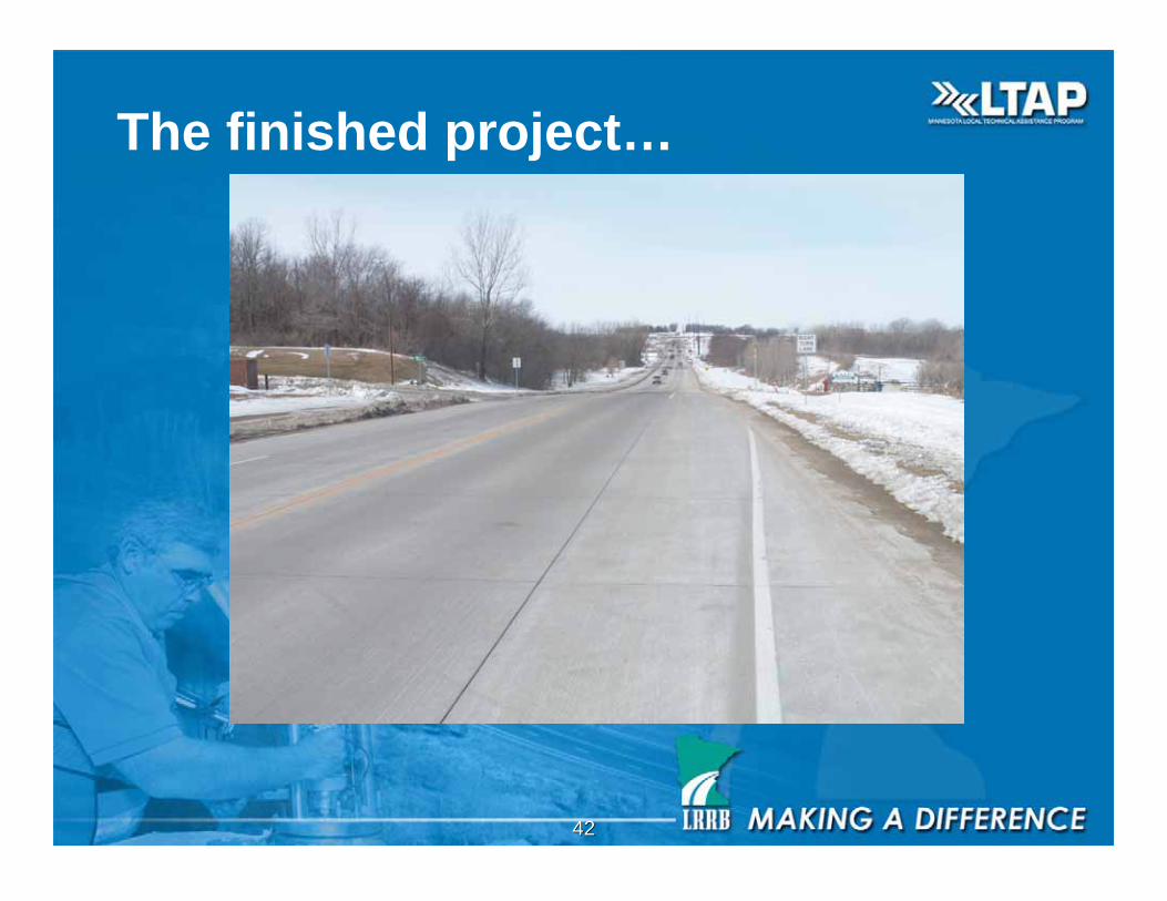
The finished project…
4343
Laboratory Testing ASTM D-35
Properties of geotextiles and geogrids:
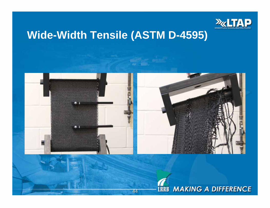
• Strength (Grab, Puncture, Tear, and Wide Width)
• Elongation
• Construction survivability
• Apparent opening size
• Permittivity / permeability
4444
Wide-Width Tensile (ASTM D-4595)
4545
Elongation
• Geotextiles will typically stretch (or elongate) more
than geogrids will
• Polypropylene and Polyethelene stretch more than
Polyester
• Non-woven geotextiles will typically stretch more
than woven geotextiles
• It is important to look at the strength of the chosen
material at various percent elongation (modulus) with
respect to the anticipated strain of the underlying soil

4646
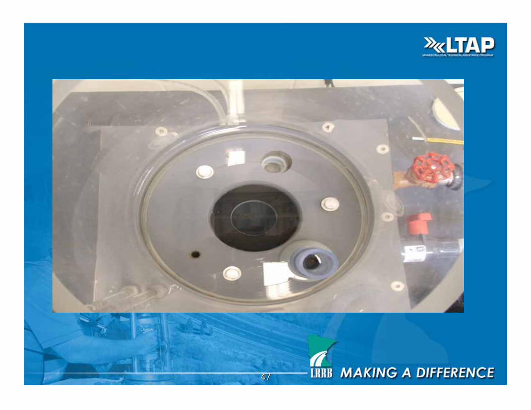
Permittivity
4747
4848
Apparent opening size (AOS)
• Used to judge compatibility with the soil
• An AOS of 100 means that 95 % of glass
beads with a size of the U.S. No. 100 sieve
passed through the geotextile.
• THE AOS value should also be checked
against the D85 (soil particle size for which
85% are smaller – in mm) of the soil
From Berg, 1997, Table 5-2 and pg 158
4949
Permittivity / Permeability
• The permeability of the geotextile must be
greater than that of the surrounding soil to
function as a filter.
• Permittivity = Permeability of geotextile /
geotextile thickness. Expressed in units of
gallons per minute per square foot of the
geotextile
5050
Acceptance
• Check geotextile for proper identification and
packaging
• Geotextile shall not be left exposed to the elements
for more than 7 days
• The geotextile shall be inspected for uniformity in
thickness, texture, and appearance
• Reject if the criteria is not met
From MnDOT Inspector’s Job Guide
for Construction, 2006 Edition

5151
Section 3733.3: Certification,
sampling, and testing
Section A: CERTIFICATE OF COMPLIANCE
• Along with each shipment of geotextile, a Certificate of Compliance shallbe furnished by the supplier in accordance with 1603.
• This certificate shall be accompanied by a document stating themanufacturer's minimum average roll values (MARVs) for the geotextile.(MARVs are two standard deviations below the mean value of all rollstested.)
• In addition, the manufacturer shall maintain test records and make themavailable to the Engineer upon request.
• A copy of the Certificate of Compliance must accompany each geotextilesample sent to the Materials Laboratory for testing.
From MnDOT Standard Specifications for
Construction, 2000 Edition

5252
Section 3733.3: Certification,
sampling, and testing
Section B: SAMPLING AND TESTING
• Geotextiles must be sampled and tested prior to use, except in specialcircumstances with the Project Engineers approval.
• In the presence of the Engineer, sampling shall be by random selection inthe field at the rate of one swatch (sample) per ten rolls or fraction thereof,or one swatch per 15 000 m (50,000 feet) of perforated pipe or fractionthereof.
• Swatches shall be full roll width and at least 1 m (yard) long (discard first 1m (3 feet) of fabric from outside of roll) or 3 m (10 feet) long for pipewrap.
• Samples shall be available for testing at least 21 days prior to intended use.Seam samples shall be at least 2 m (6 feet) long, in addition to the regularsample, and be joined in a manner and with a machine the same or equal tothat to be used on the Project.
From MnDOT Standard Specifications
for Construction, 2000 Edition
5353
Why do we use Geosynthetics?
• Separation
• Reinforcement
• Filtration
• Drainage
• Liquid barriers
5454
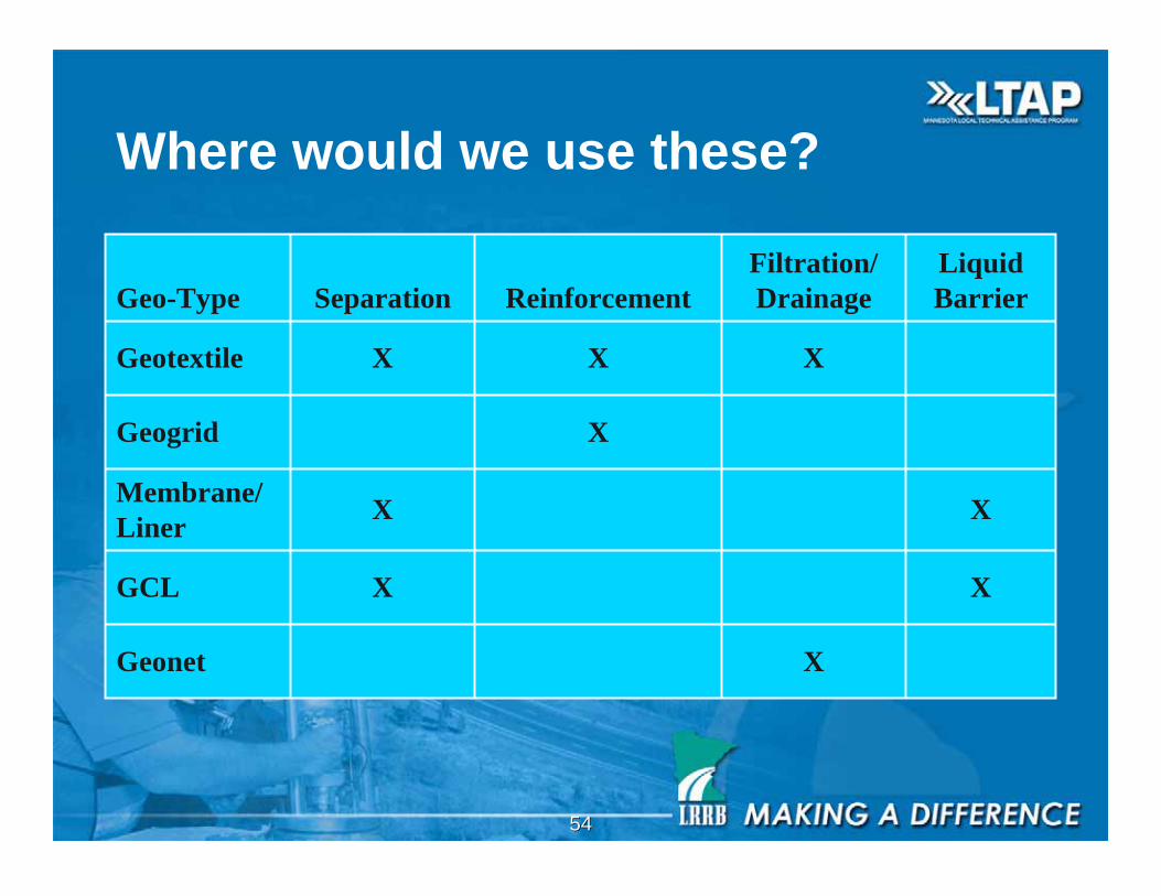
Where would we use these?
XGeonet
XXGCL
XXMembrane/
Liner
XGeogrid
XXXGeotextile
Liquid
Barrier
Filtration/
DrainageReinforcementSeparationGeo-Type
5555
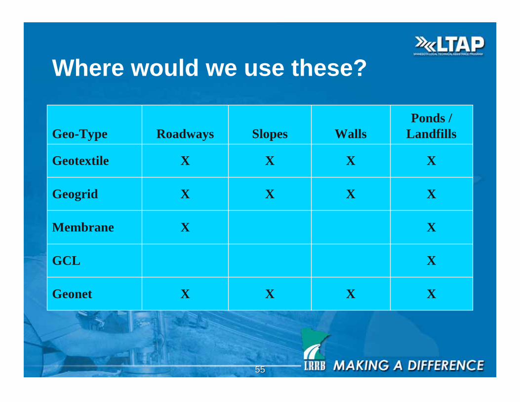
Where would we use these?
XXXXGeonet
XGCL
XXMembrane
XXXXGeogrid
XXXXGeotextile
Ponds /
LandfillsWallsSlopesRoadwaysGeo-Type
5656
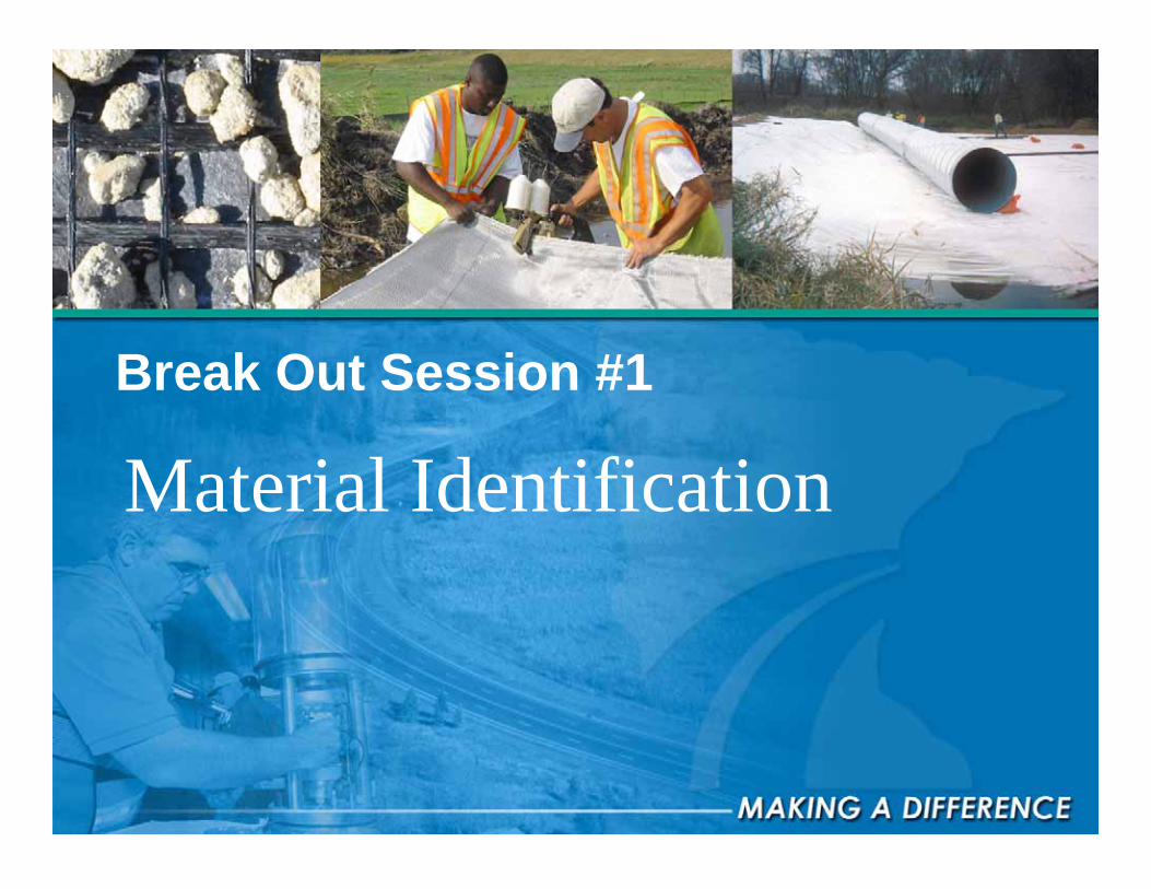
Break Out Session #1
Material Identification
5757
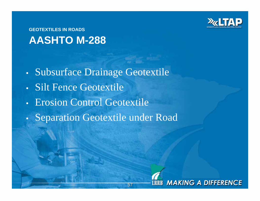
GEOTEXTILES IN ROADS
AASHTO M-288
• Subsurface Drainage Geotextile
• Silt Fence Geotextile
• Erosion Control Geotextile
• Separation Geotextile under Road
5858
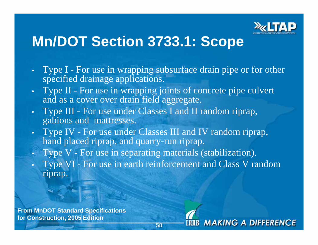
Mn/DOT Section 3733.1: Scope
• Type I - For use in wrapping subsurface drain pipe or for otherspecified drainage applications.
• Type II - For use in wrapping joints of concrete pipe culvertand as a cover over drain field aggregate.
• Type III - For use under Classes I and II random riprap,gabions and mattresses.
• Type IV - For use under Classes III and IV random riprap,hand placed riprap, and quarry-run riprap.
• Type V - For use in separating materials (stabilization).
• Type VI - For use in earth reinforcement and Class V randomriprap.
From MnDOT Standard Specifications
for Construction, 2005 Edition
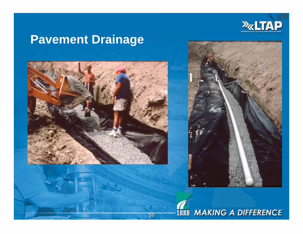
5959
Pavement Drainage
6060
Drainage and Filtration
- fabric to soil system that allows for free
liquid flow across or through the plane of
the fabric over an indefinitely long period of
time, while preventing soil loss (filtration).
- *filtration - the ability of a geotextile to
prevent excessive migration of soil particles
6161
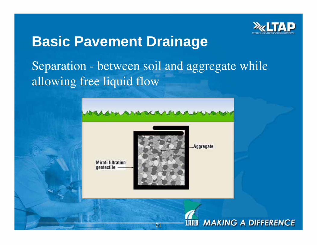
Separation - between soil and aggregate whileallowing free liquid flow
Basic Pavement Drainage

6262
Filtration
Drainage Aggregate
Soil
Geotextile
Seepage
Seepage
Seepage
Seepage

6363
Geotextile Soil Particles
Larger AOS can retain
smaller particle sizes
Filter Bridge/
Filter Cake Forms

6464
Geotextile Soil Particles
Escaping
Too large an AOS
Can Cause piping
No Filter
Bridge Forms
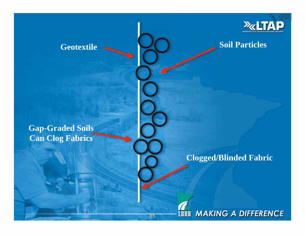
6565
Geotextile
Gap-Graded Soils
Can Clog Fabrics
Soil Particles
Clogged/Blinded Fabric
6666
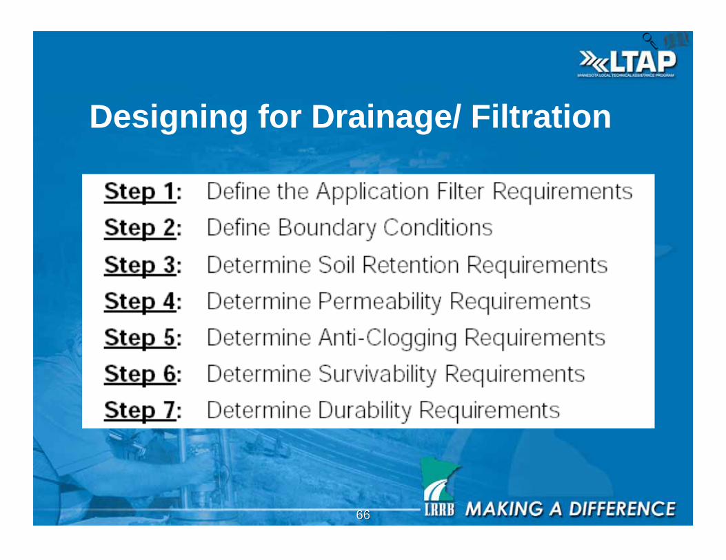
Designing for Drainage/ Filtration
6767
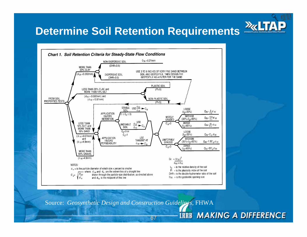
Determine Soil Retention Requirements
Source: Geosynthetic Design and Construction Guidelines, FHWA
6868
6969
7070
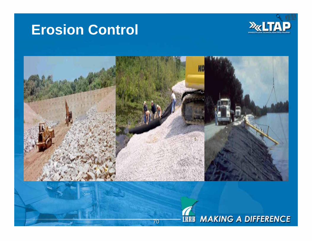
Erosion Control

7171
Erosion Control Products
Monofilament Woven Needle Punched NonWoven
7272
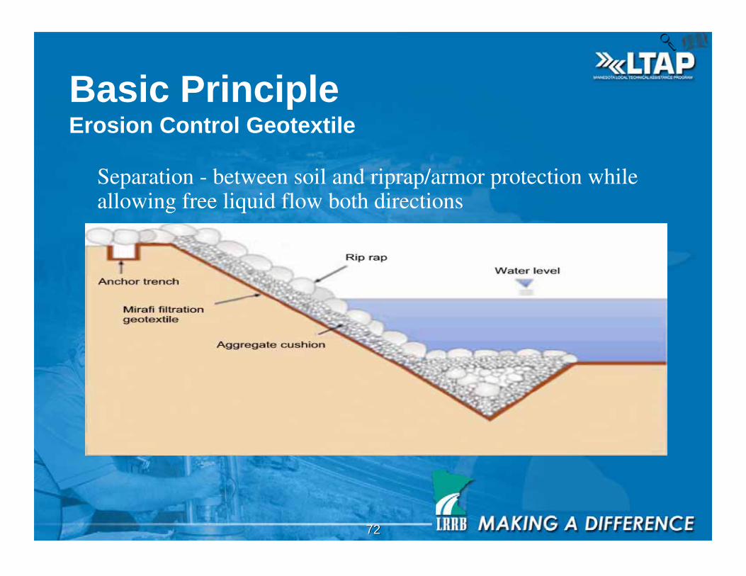
Basic PrincipleErosion Control Geotextile
Separation - between soil and riprap/armor protection whileallowing free liquid flow both directions

7373
Application: Under Riprap

7474
Application: Monofilament Woven
Under Revetment Systems
7575
Benefits of Geotextile Erosion Control
• Resists clogging while maintaining high flow
rate in dynamic flow and high gradient
conditions
• Maintains separation of layers
• High survivability in aggressive installation
conditions
7676
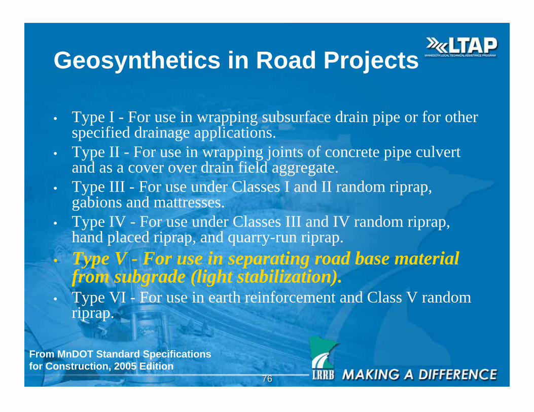
Geosynthetics in Road Projects
• Type I - For use in wrapping subsurface drain pipe or for otherspecified drainage applications.
• Type II - For use in wrapping joints of concrete pipe culvertand as a cover over drain field aggregate.
• Type III - For use under Classes I and II random riprap,gabions and mattresses.
• Type IV - For use under Classes III and IV random riprap,hand placed riprap, and quarry-run riprap.
• Type V - For use in separating road base materialfrom subgrade (light stabilization).
• Type VI - For use in earth reinforcement and Class V randomriprap.
From MnDOT Standard Specifications
for Construction, 2005 Edition
7777
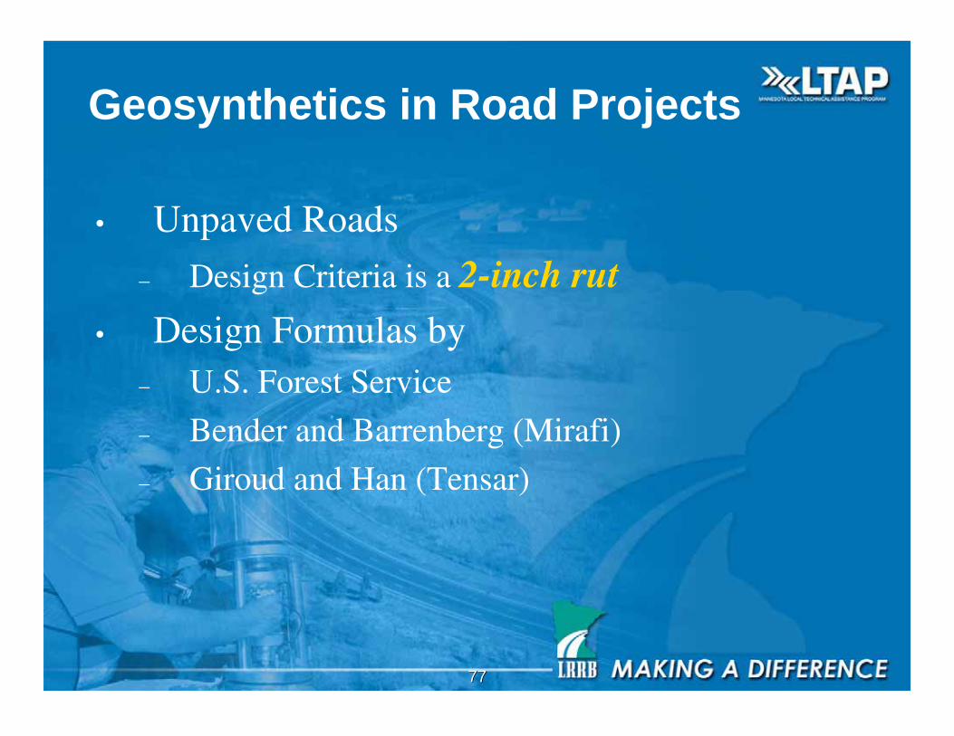
Geosynthetics in Road Projects
• Unpaved Roads
– Design Criteria is a 2-inch rut
• Design Formulas by– U.S. Forest Service
– Bender and Barrenberg (Mirafi)
– Giroud and Han (Tensar)

7878
Geosynthetics in Road Projects
• Paved Roads
• The first lift of a paved road is an unpavedroad. Design to stabilize pad and thenPavement Design by Mn/DOT procedure.
7979
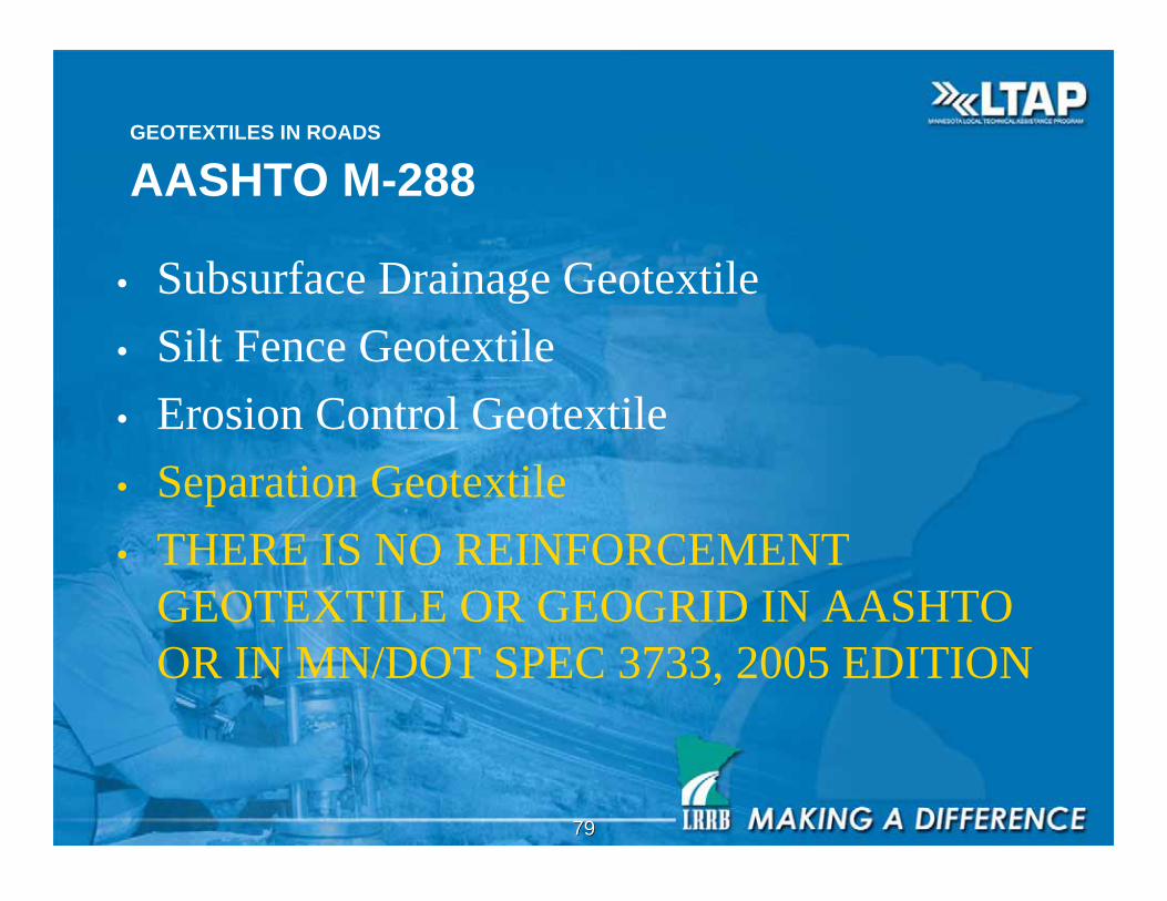
GEOTEXTILES IN ROADS
AASHTO M-288
• Subsurface Drainage Geotextile
• Silt Fence Geotextile
• Erosion Control Geotextile
• Separation Geotextile
• THERE IS NO REINFORCEMENT
GEOTEXTILE OR GEOGRID IN AASHTO
OR IN MN/DOT SPEC 3733, 2005 EDITION
8080
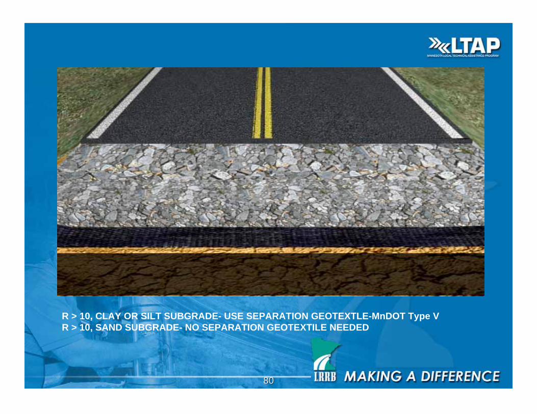
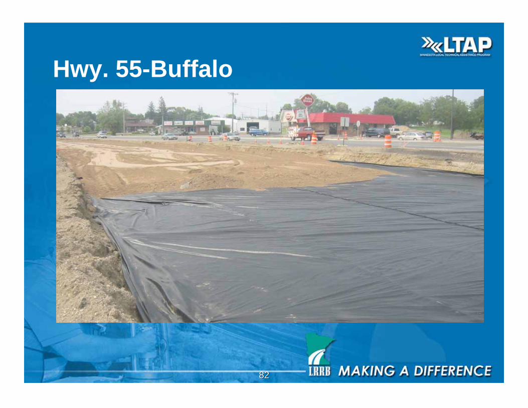
R > 10, CLAY OR SILT SUBGRADE- USE SEPARATION GEOTEXTLE-MnDOT Type V
R > 10, SAND SUBGRADE- NO SEPARATION GEOTEXTILE NEEDED
8181
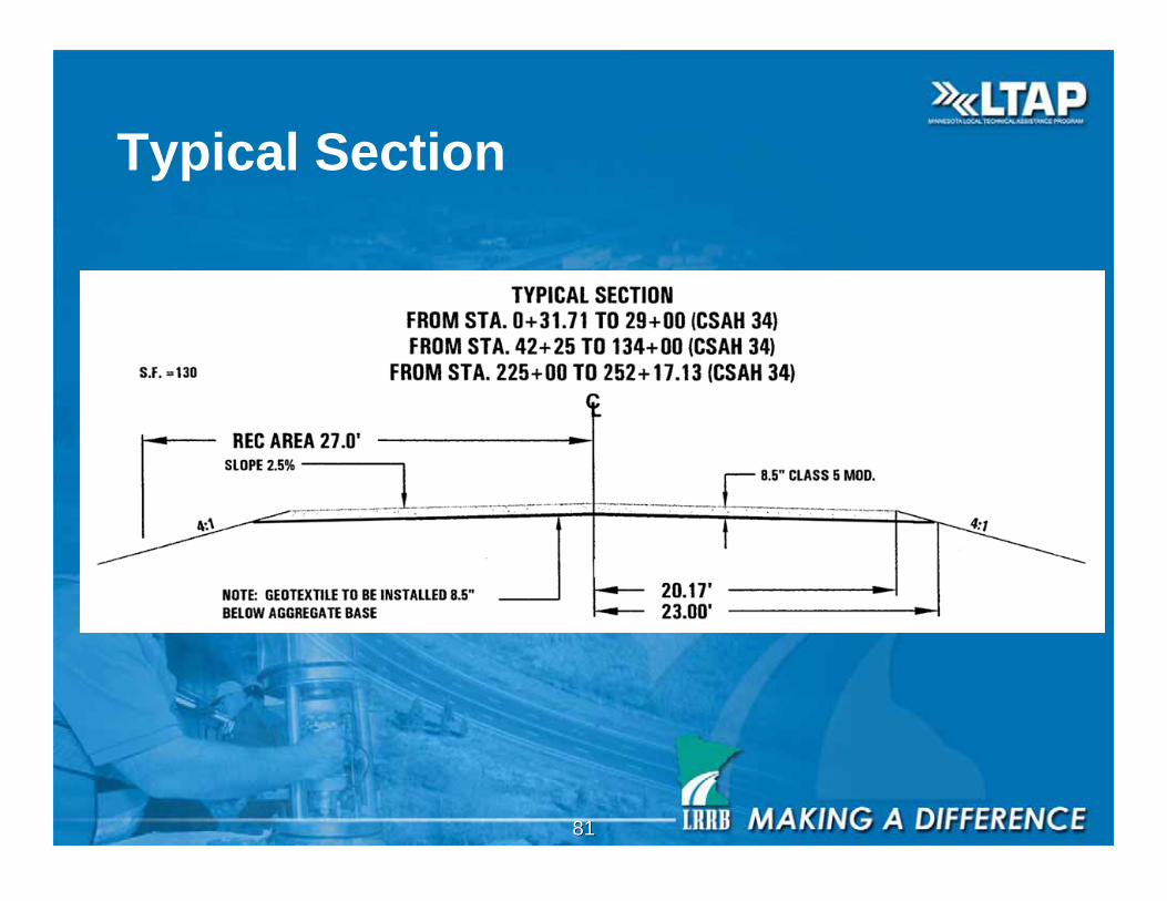
Typical Section
8282
Hwy. 55-Buffalo
8383
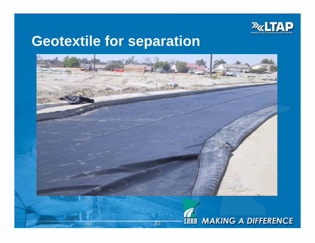
Geotextile for separation
8484
Studies by Federal Highway Administration
(FHWA), Transportation Research Board
(TRB) & Geosynthetic Research Institute (GRI)
• Geotextile separator preserves layer separation under traffic
• Geotextile separated pavements last longer than no
geotextile
• Separation Geotextile must have openings small enough to
prevent the migration of subgrade fines into the base.
• Separation Geotextile openings must be large enough to not
adversely affect the flow of water either up or down.
• Separation Geotextile must be strong enough to survive
installation without ripping.
8585
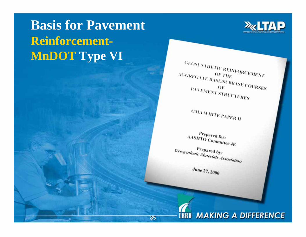
Basis for PavementReinforcement-
MnDOT Type VI
8686
Geosynthetic Reinforcement
Applications
• Base Reinforcement on Firm
Subgrade
• Sub Base Stabilization on Soft
Subgrade
8787
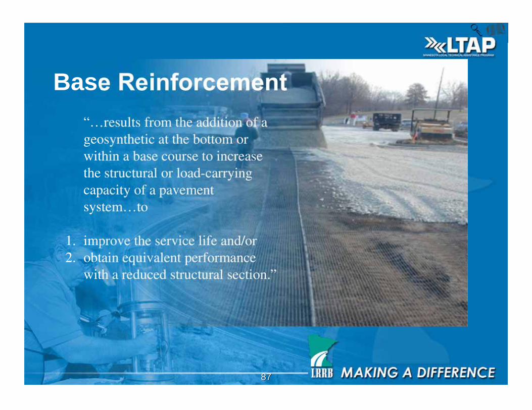
Base Reinforcement
“…results from the addition of ageosynthetic at the bottom orwithin a base course to increasethe structural or load-carryingcapacity of a pavementsystem…to
1. improve the service life and/or2. obtain equivalent performance
with a reduced structural section.”
8888
Base Reinforcement Benefits
Geosynthetic placed as a tensile element at
the bottom of or within a base aggregate
– Improves service life
– Obtains equivalent performance with
reduced section
– Reduces undercut, disturbance of subgrade
– Reduces aggregate required for
stabilization
8989
Subgrade Stabilization Benefits
Geosynthetic placed as a tensile element at
the interface of a base aggregate/subgrade or
the interface of a granular subbase/subgrade– Improves service life
– Obtains equivalent performance with reduced section
– Reduces undercut, disturbance of subgrade
– Reduced aggregate required for stabilization
– Provides access & constructability over very soft soils
– Helps to establish a well-compacted, non-yieldingplatform - uniform support
9090
Geosynthetic Stabilization
Mechanisms
I. Lateral Restraint on Firm Subgrade
II. Bearing Capacity Increase on Soft Subgrade
III. Tension Membrane Support on Soft Subgrade
9191
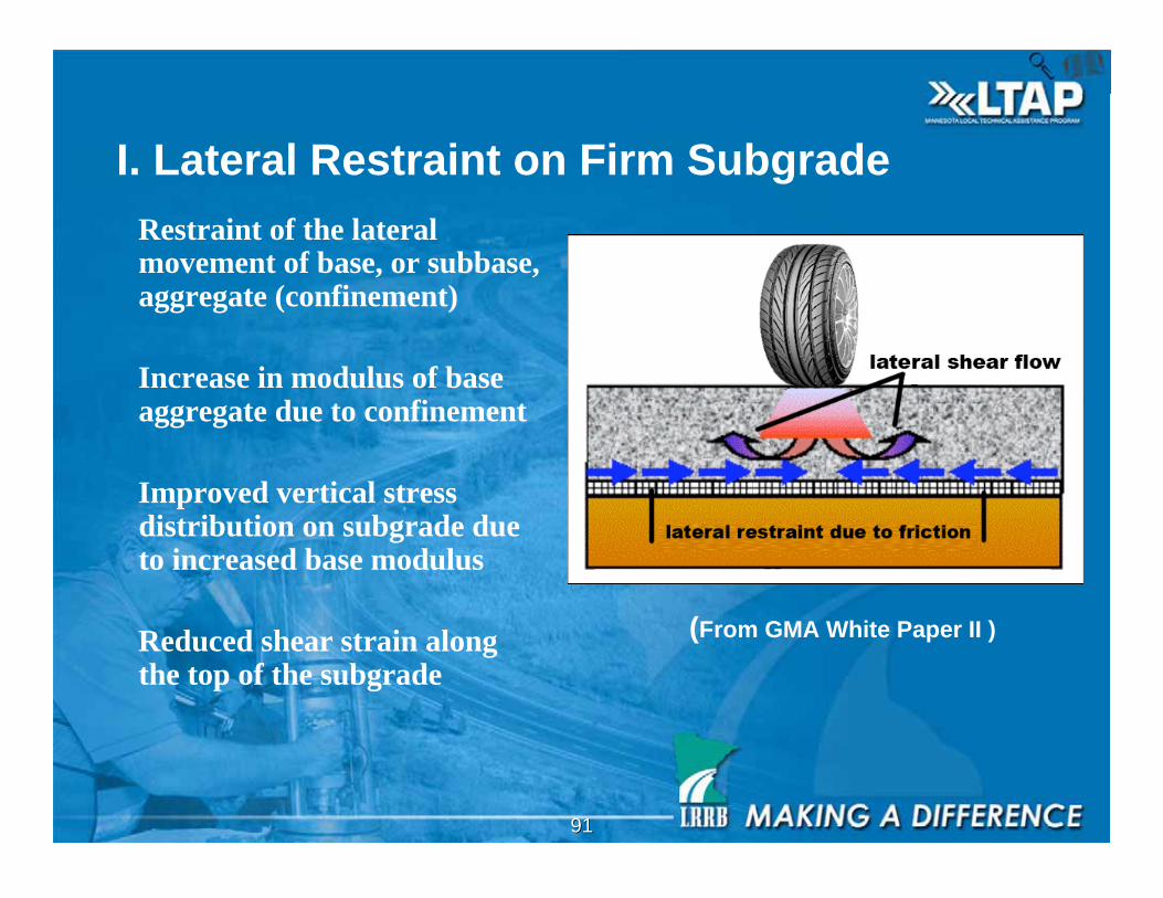
I. Lateral Restraint on Firm Subgrade
Restraint of the lateralmovement of base, or subbase,aggregate (confinement)
Increase in modulus of baseaggregate due to confinement
Improved vertical stressdistribution on subgrade dueto increased base modulus
Reduced shear strain alongthe top of the subgrade
(From GMA White Paper II )
9292
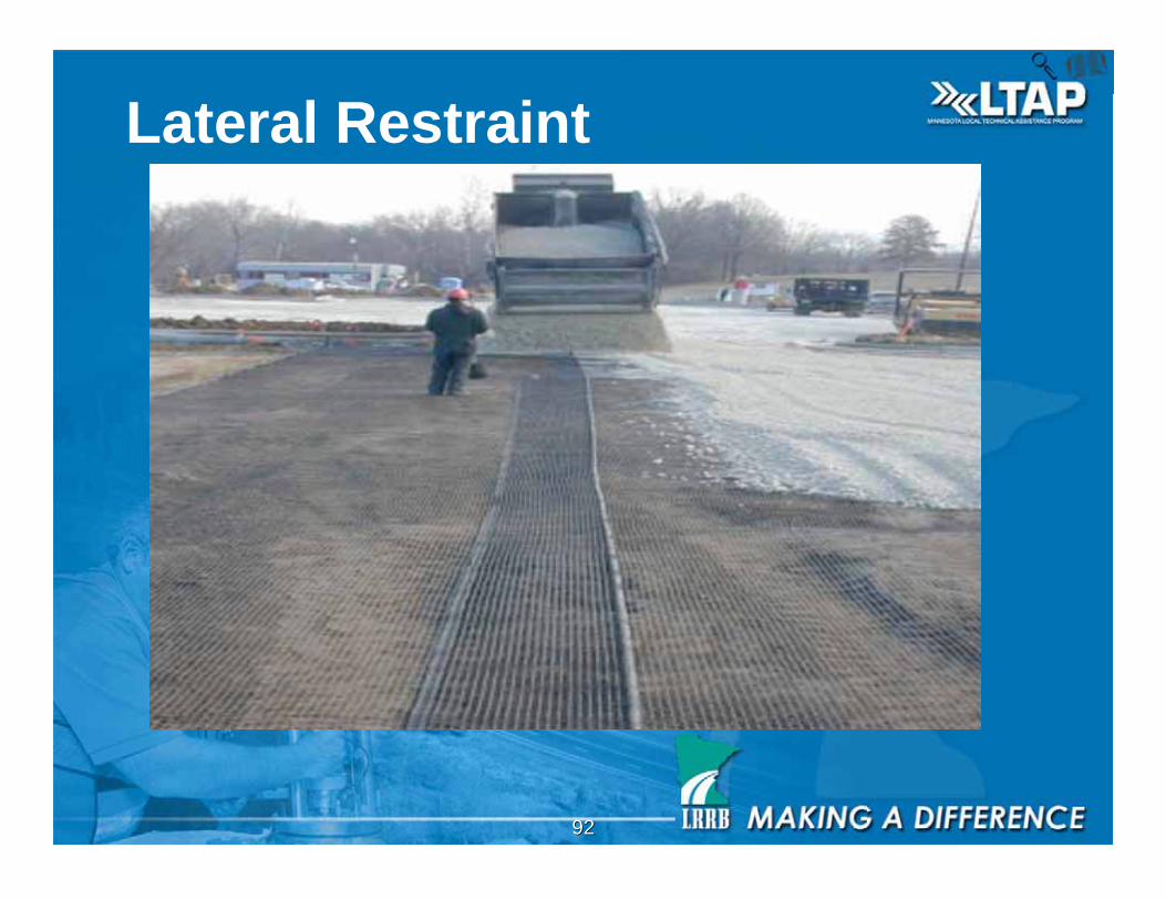
Lateral Restraint
9393
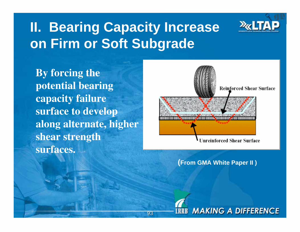
II. Bearing Capacity Increase
on Firm or Soft Subgrade
By forcing thepotential bearingcapacity failuresurface to developalong alternate, highershear strengthsurfaces.
(From GMA White Paper II )
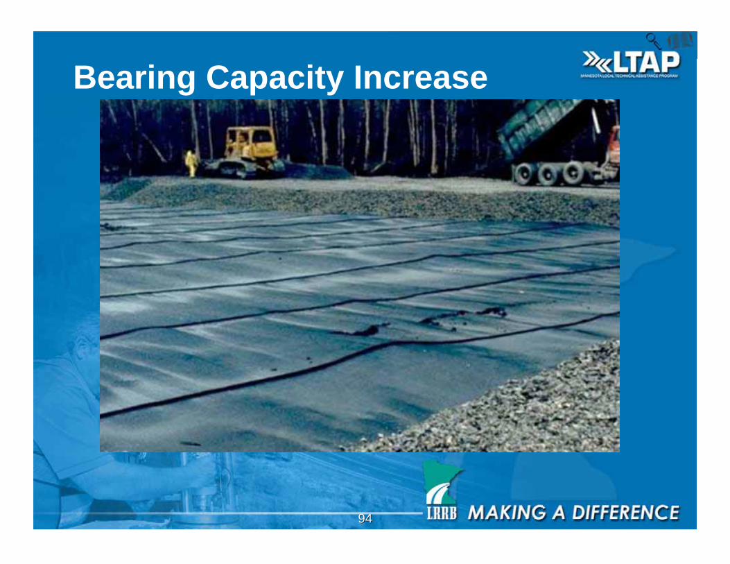
9494
Bearing Capacity Increase
9595
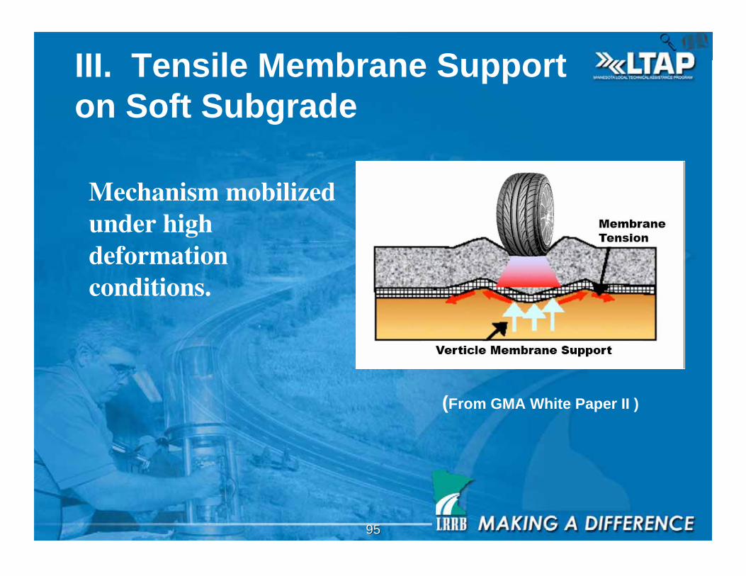
III. Tensile Membrane Support
on Soft Subgrade
Mechanism mobilizedunder highdeformationconditions.
(From GMA White Paper II )
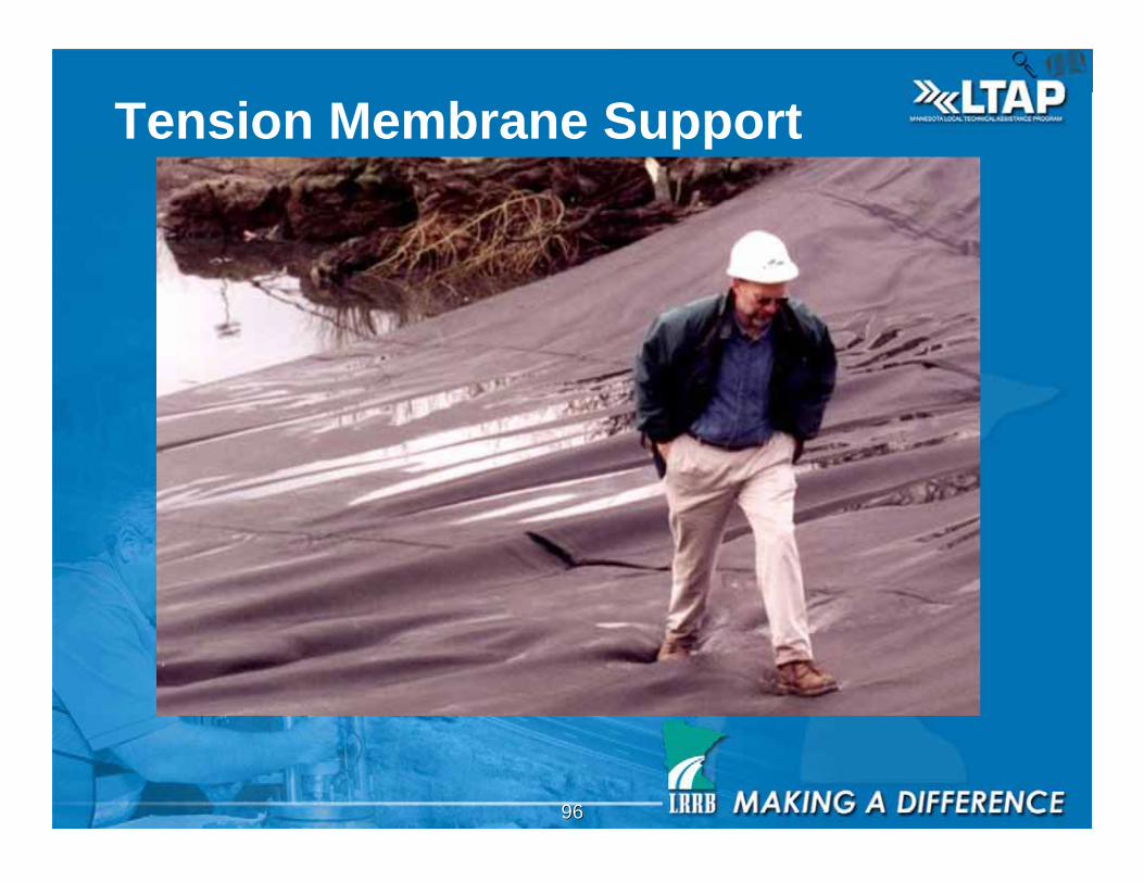
9696
Tension Membrane Support
9797
Reinforcement Geogrids
vs. Reinforcement Geotextiles
vs. Separation Geotextiles
• Reinforcement geogrids are used to reinforce the
aggregate base. They should be within the gravel
section and within 10 inches of the pavement
surface
• Reinforcement Geotextiles of high strengths
should be placed on soft subgrade to separate and
reinforce
• Separation Geotextiles should be used to separate
clay and silt subgrades from the aggregate base
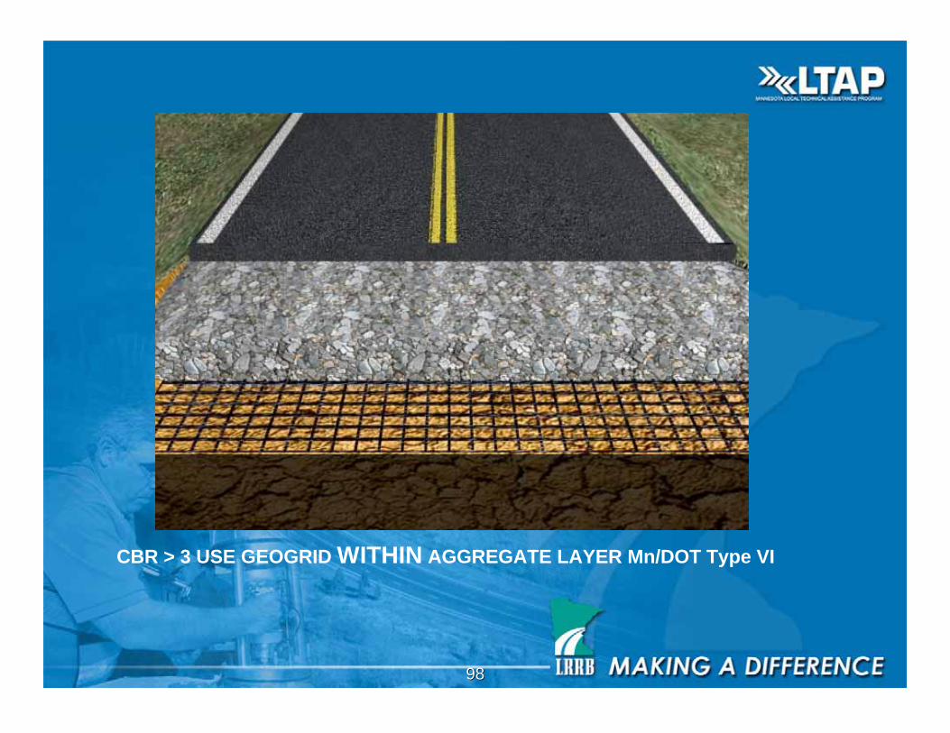
9898
CBR > 3 USE GEOGRID WITHIN AGGREGATE LAYER Mn/DOT Type VI
9999
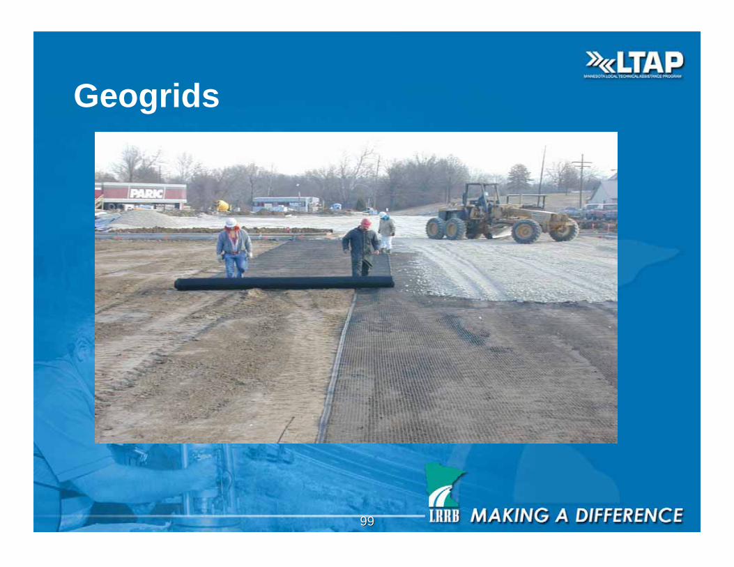
Geogrids
100100
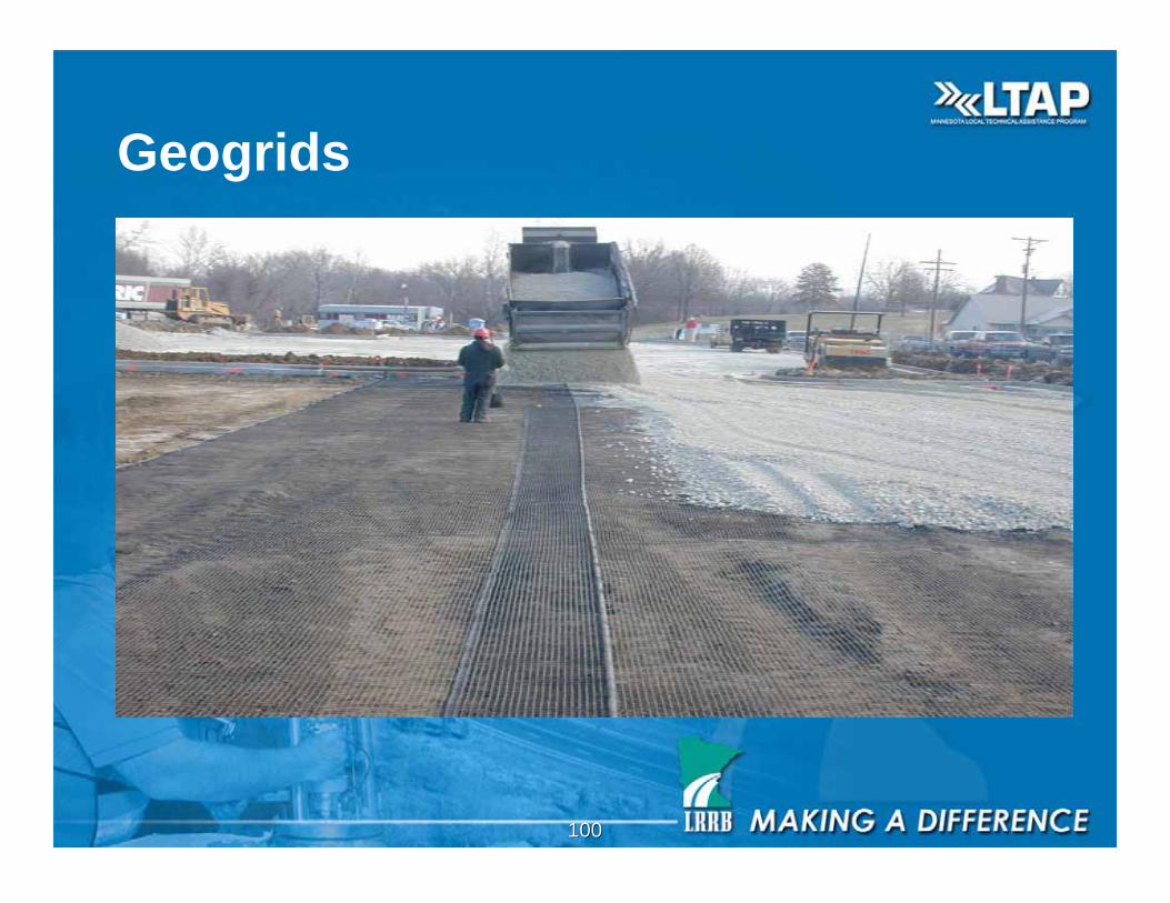
Geogrids
101101
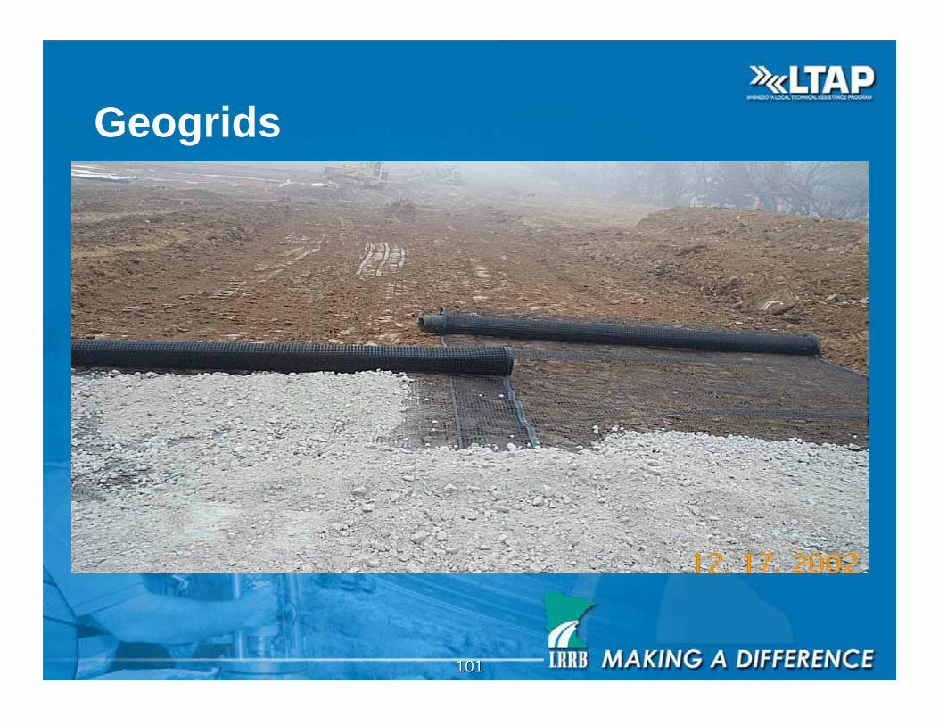
Geogrids
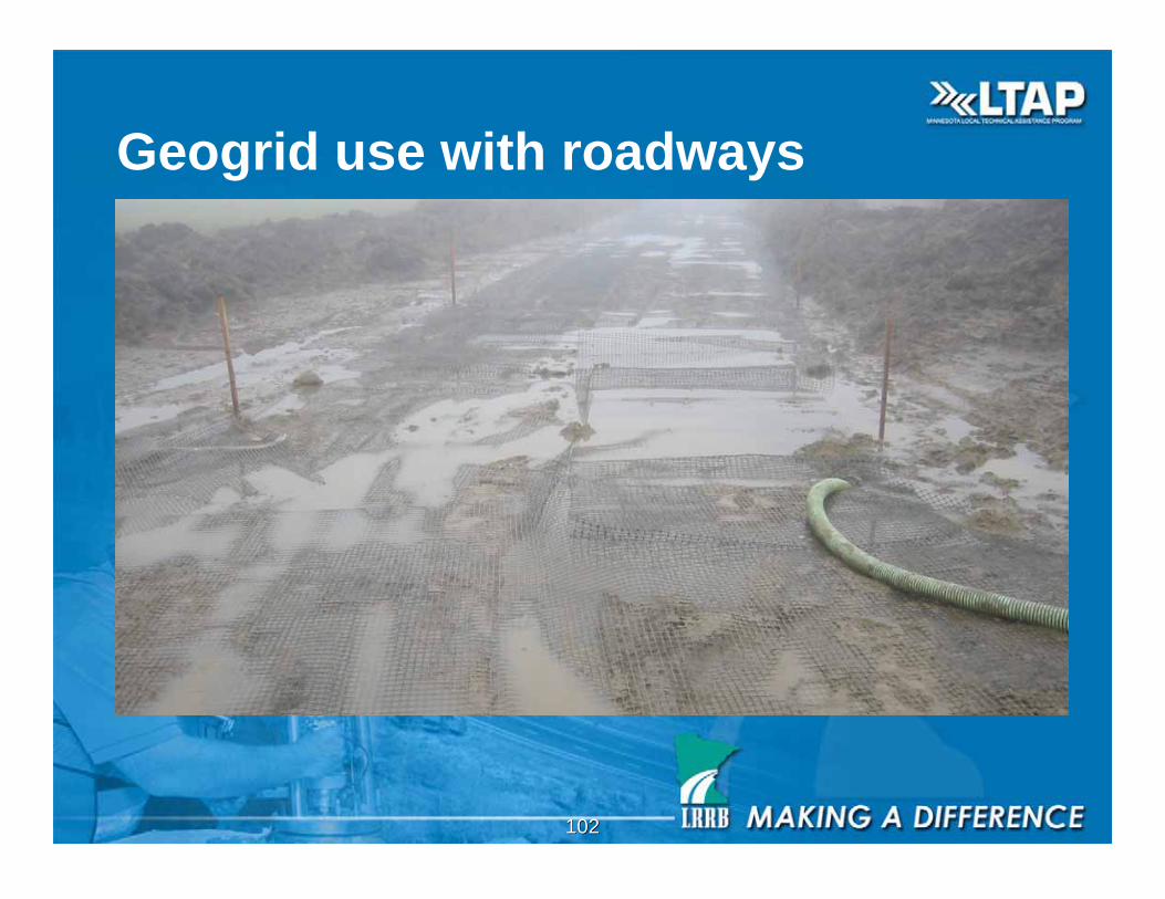
102102
Geogrid use with roadways
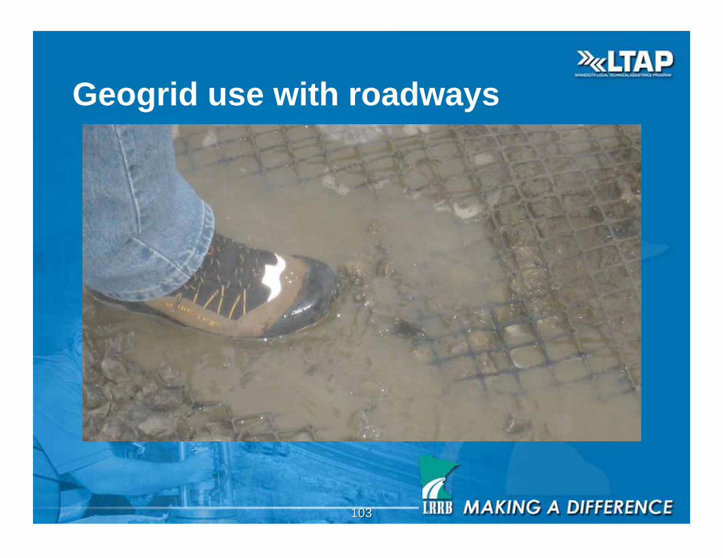
103103
Geogrid use with roadways
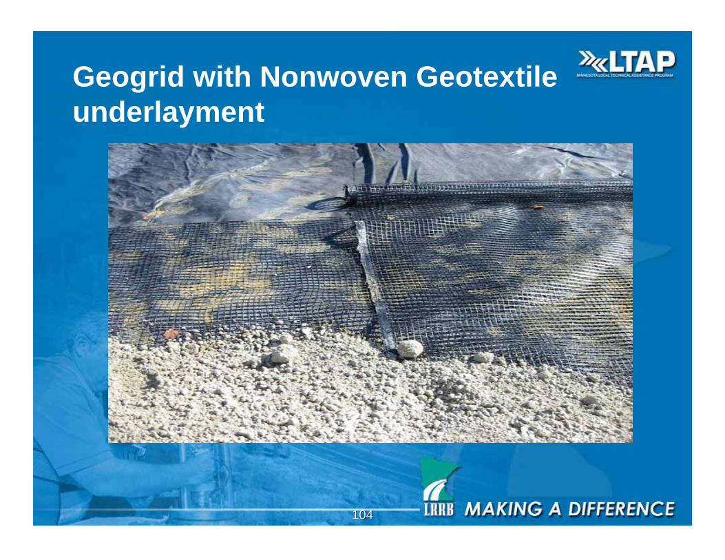
104104
Geogrid with Nonwoven Geotextile
underlayment
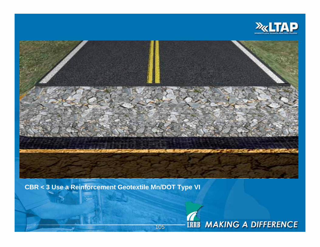
105105
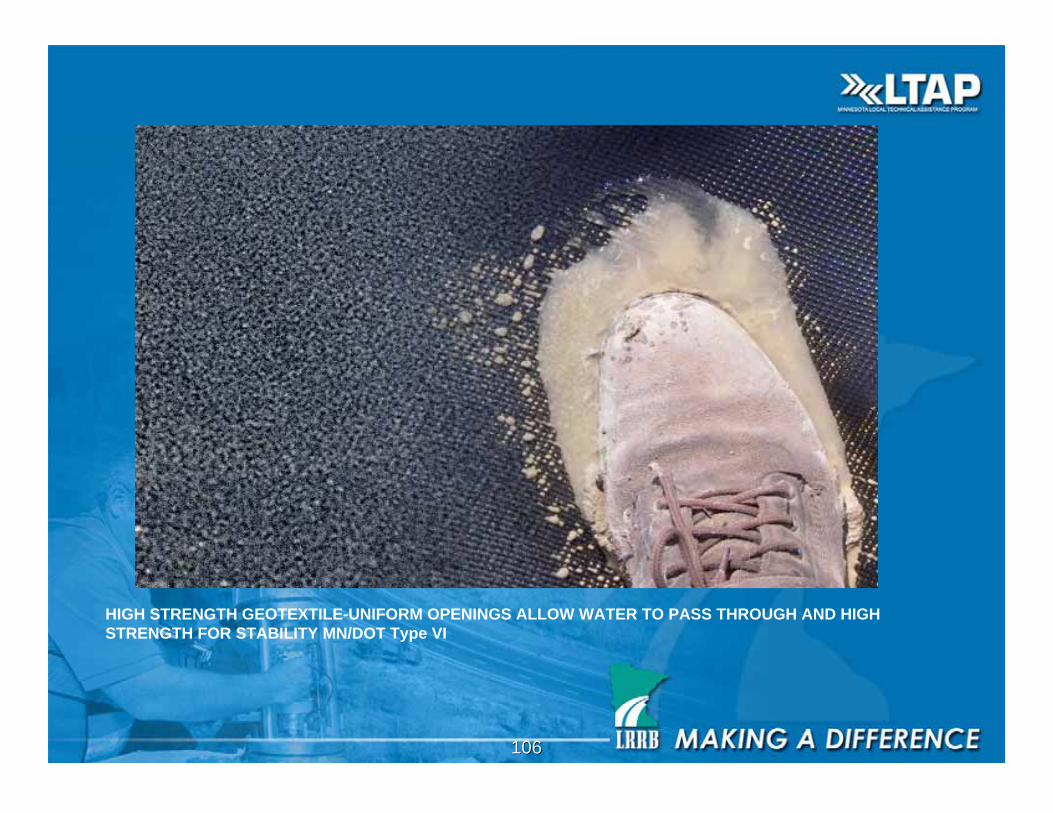
CBR < 3 Use a Reinforcement Geotextile Mn/DOT Type VI
106106
HIGH STRENGTH GEOTEXTILE-UNIFORM OPENINGS ALLOW WATER TO PASS THROUGH AND HIGH
STRENGTH FOR STABILITY MN/DOT Type VI
107107
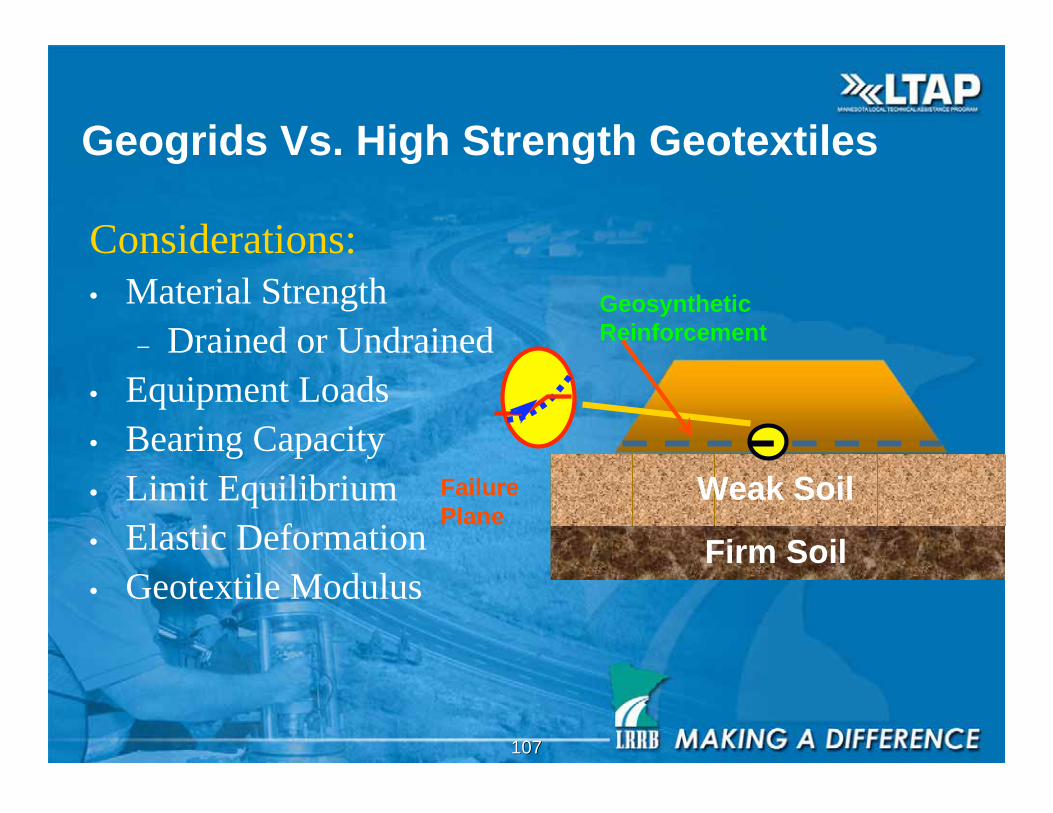
Geogrids Vs. High Strength Geotextiles
Considerations:
• Material Strength
– Drained or Undrained
• Equipment Loads
• Bearing Capacity
• Limit Equilibrium
• Elastic Deformation
• Geotextile Modulus
Weak Soil
Firm Soil
Failure
Plane
Geosynthetic
Reinforcement
108108
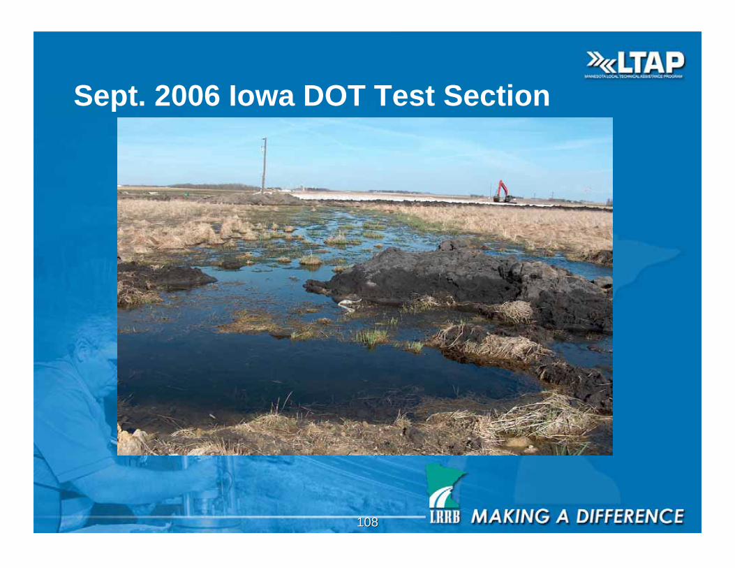
Sept. 2006 Iowa DOT Test Section
109109
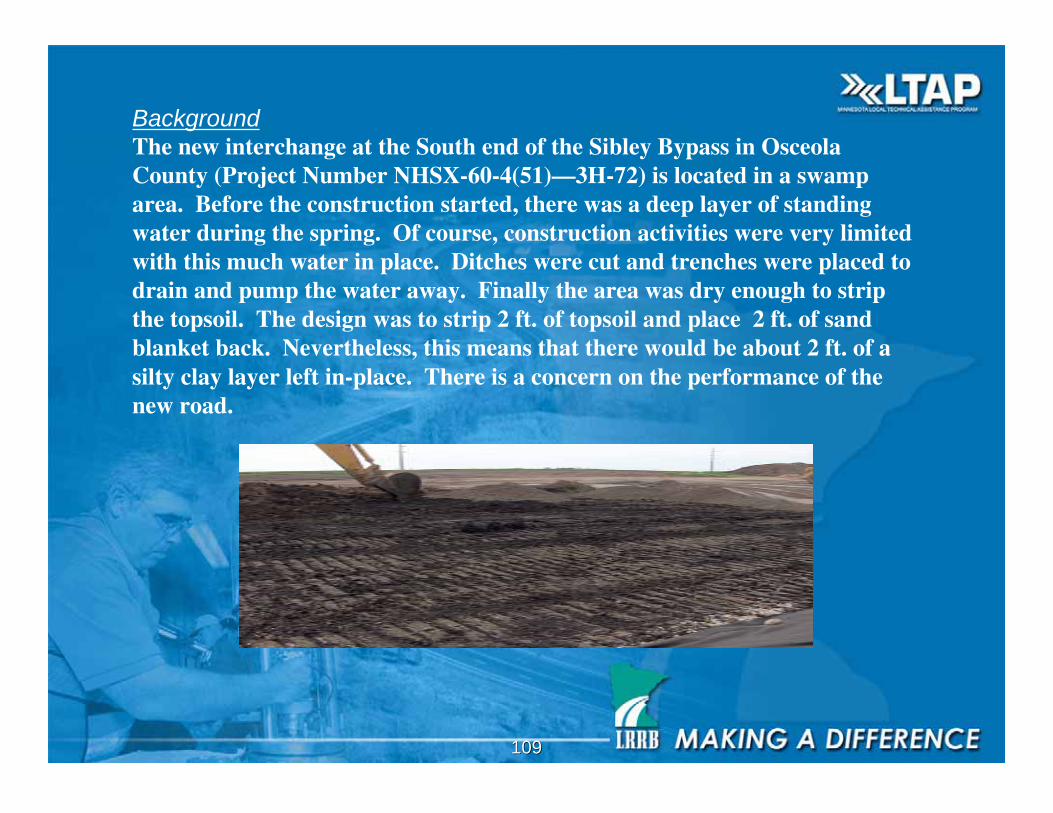
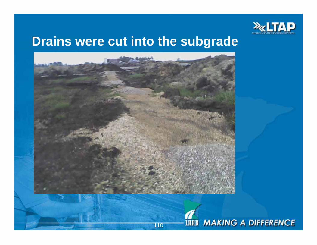
Background
The new interchange at the South end of the Sibley Bypass in OsceolaCounty (Project Number NHSX-60-4(51)—3H-72) is located in a swamparea. Before the construction started, there was a deep layer of standingwater during the spring. Of course, construction activities were very limitedwith this much water in place. Ditches were cut and trenches were placed todrain and pump the water away. Finally the area was dry enough to stripthe topsoil. The design was to strip 2 ft. of topsoil and place 2 ft. of sandblanket back. Nevertheless, this means that there would be about 2 ft. of asilty clay layer left in-place. There is a concern on the performance of thenew road.
110110
Drains were cut into the subgrade
111111
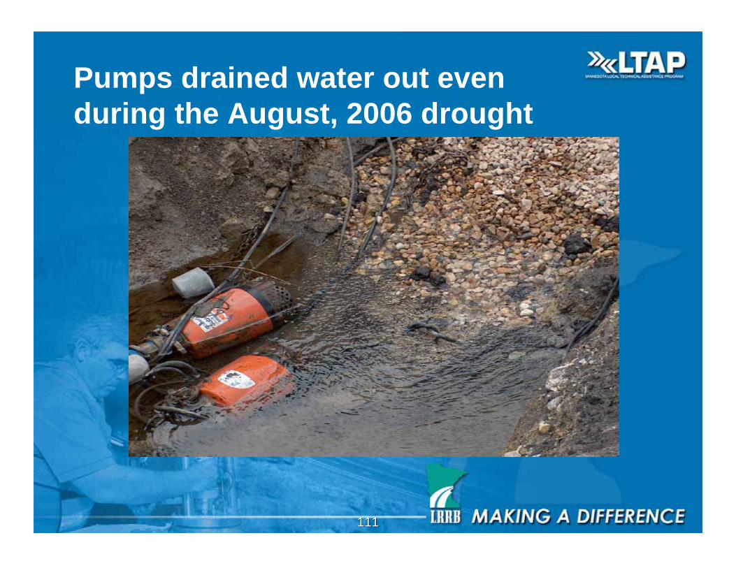
Pumps drained water out even
during the August, 2006 drought
112112
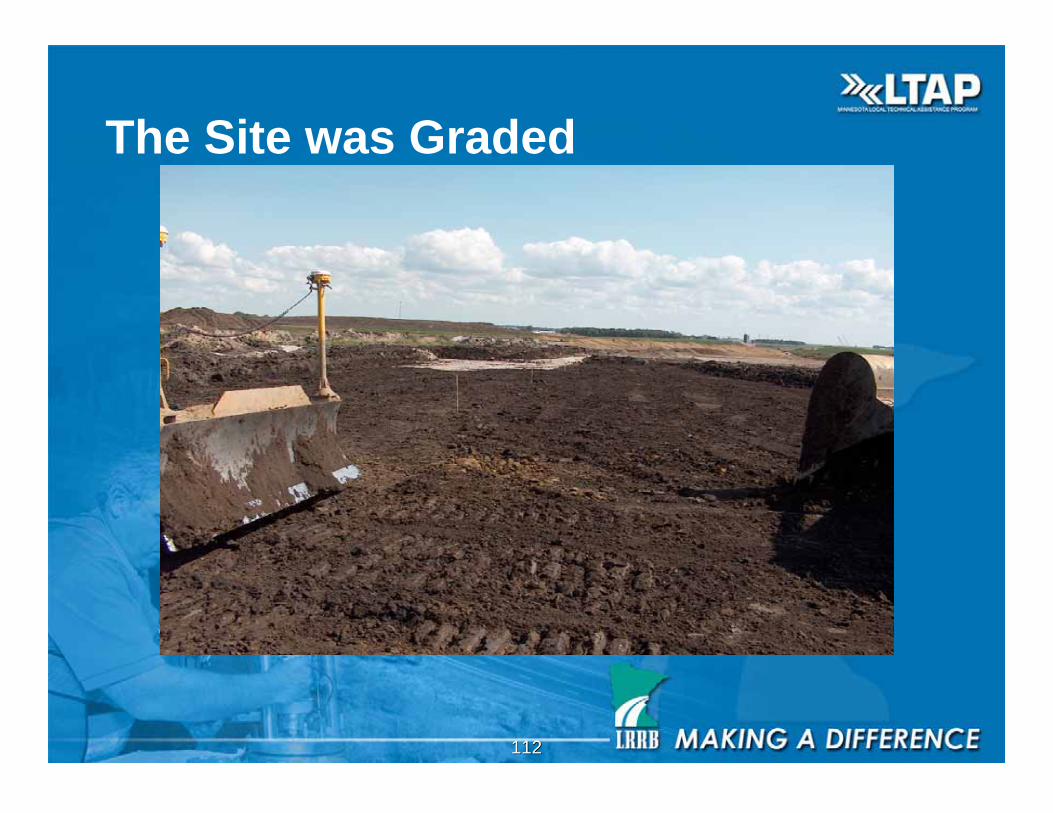
The Site was Graded
113113
The original design helps dry out the areasignificantly. However, there is a 2 ft-layer of siltyclay that has very low stability. Should this layer beexcavated? Or is there another option?
Two geotextile options were selected forcomparison: Option No. 1: place 2 ft. of the sandblanket on top of the geotextile.Option No. 2: place 1 ft. of the sand blanket on top ofthe geotextile.
114114
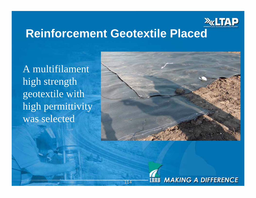
Reinforcement Geotextile Placed
A multifilament
high strength
geotextile with
high permittivity
was selected
115115
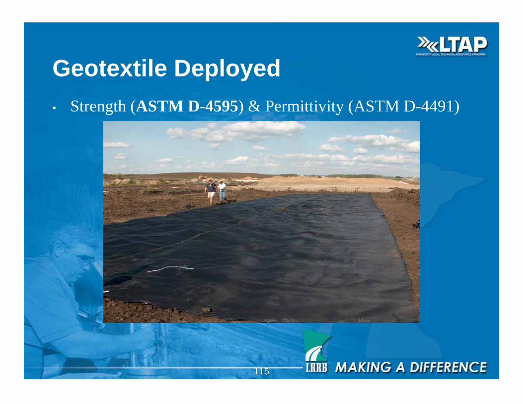
Geotextile Deployed
• Strength (ASTM D-4595) & Permittivity (ASTM D-4491)
116116
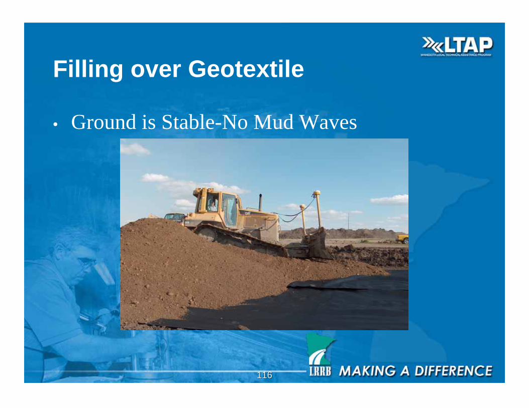
Filling over Geotextile
• Ground is Stable-No Mud Waves

117117
Will Subgrade be Stable in the Spring
Wait for consolidation to occur before paving!!!
118118
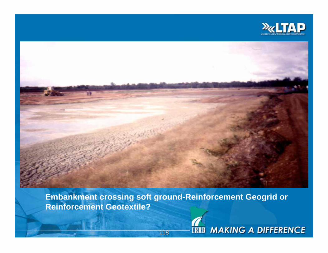
Embankment crossing soft ground-Reinforcement Geogrid or
Reinforcement Geotextile?
119119
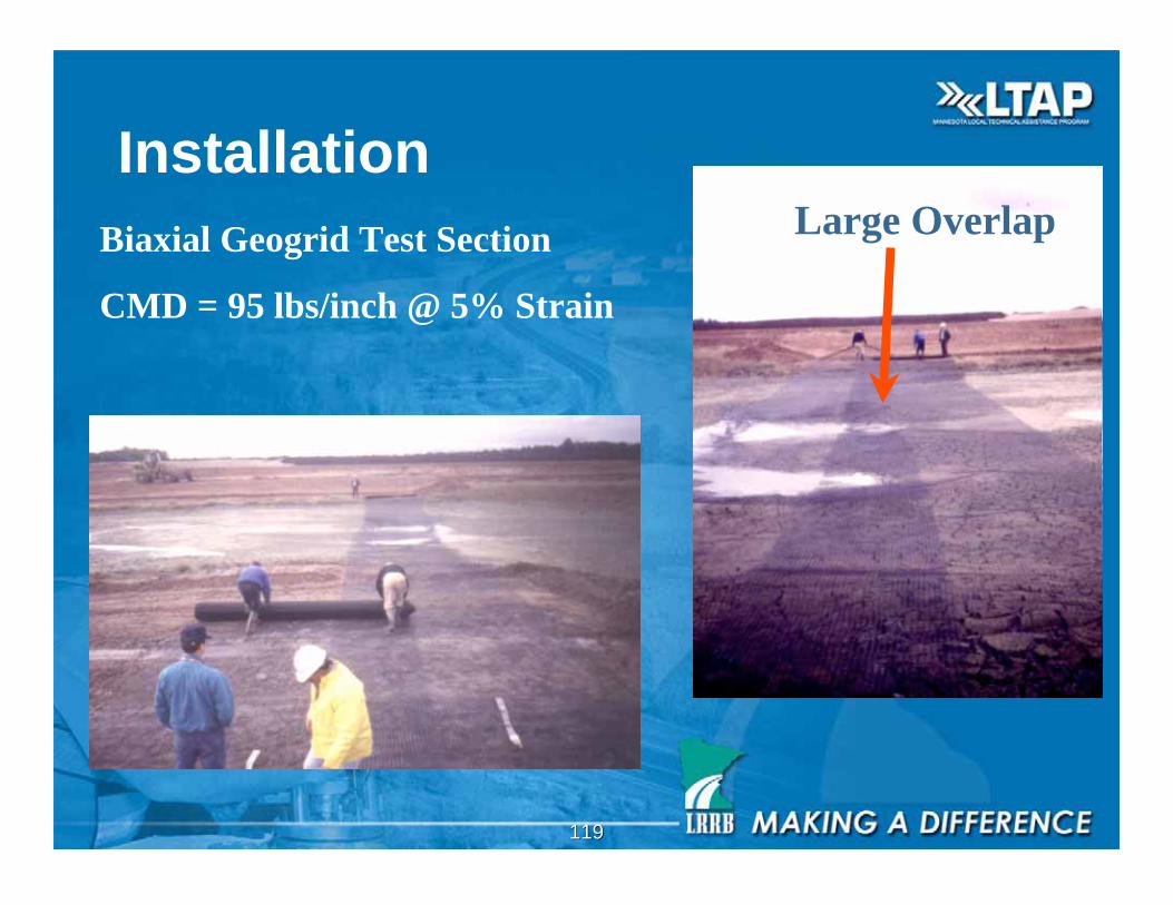
Installation
Biaxial Geogrid Test Section
CMD = 95 lbs/inch @ 5% Strain
Large Overlap
120120
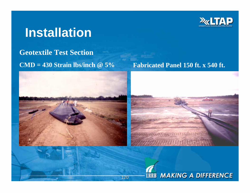
Installation
Geotextile Test Section
CMD = 430 Strain lbs/inch @ 5% Fabricated Panel 150 ft. x 540 ft.
121121
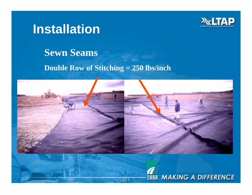
Installation
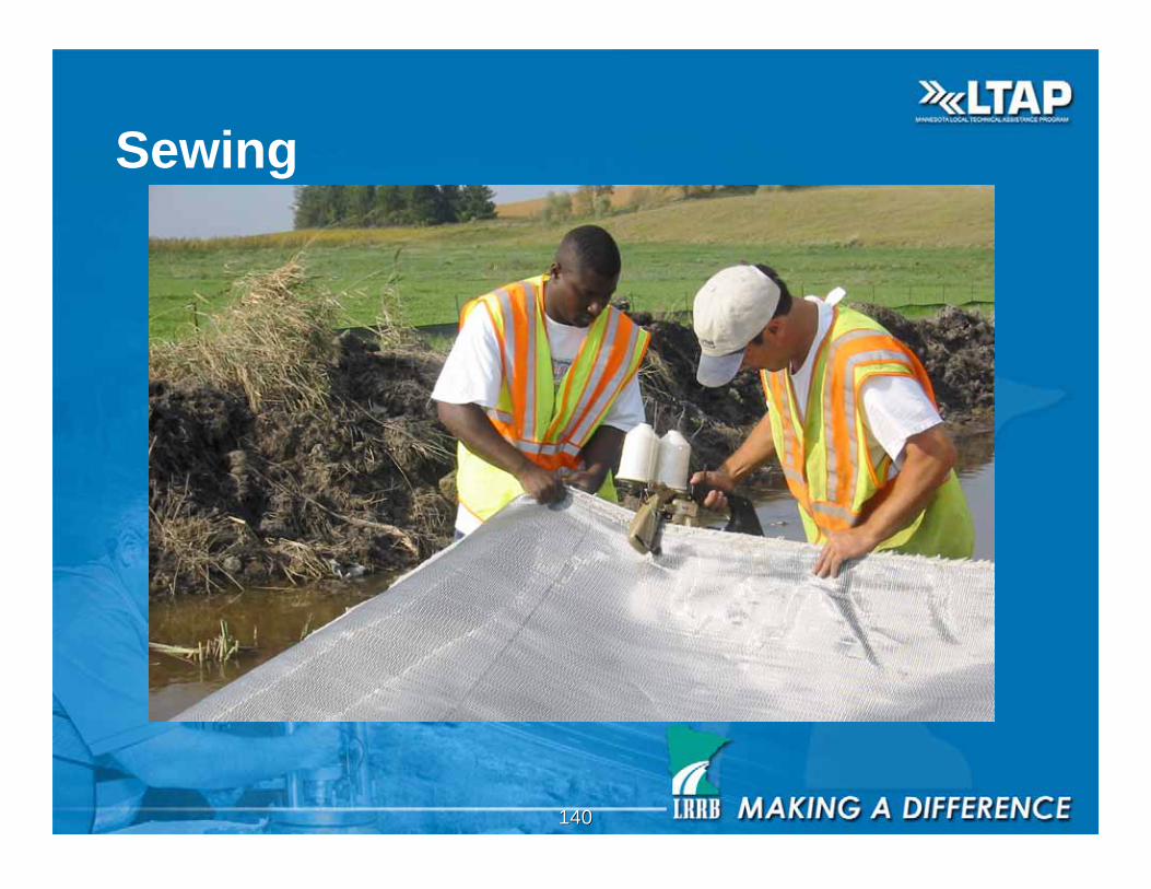
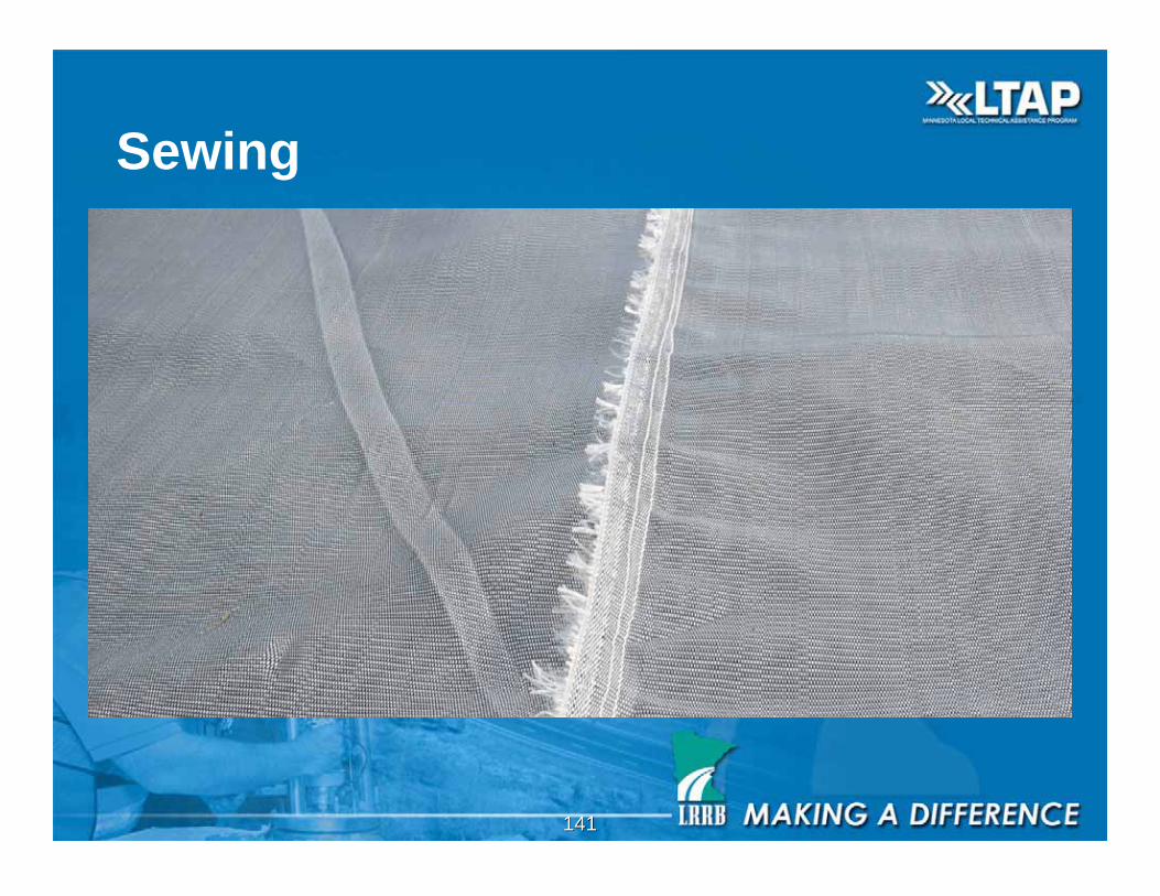
Sewn Seams
Double Row of Stitching = 250 lbs/inch
122122
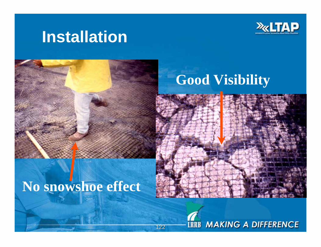
Installation
Good Visibility
No snowshoe effect
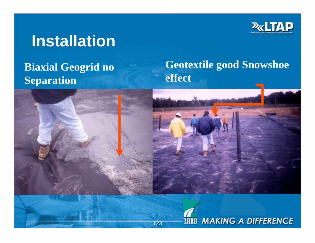
123123
Installation
Biaxial Geogrid no
Separation
Geotextile good Snowshoe
effect
124124
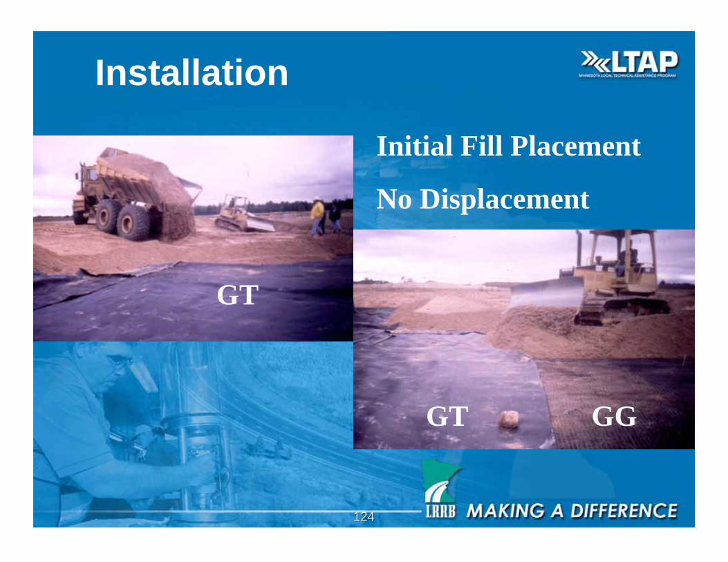
Installation
Initial Fill Placement
No Displacement
GT GG
GT
125125
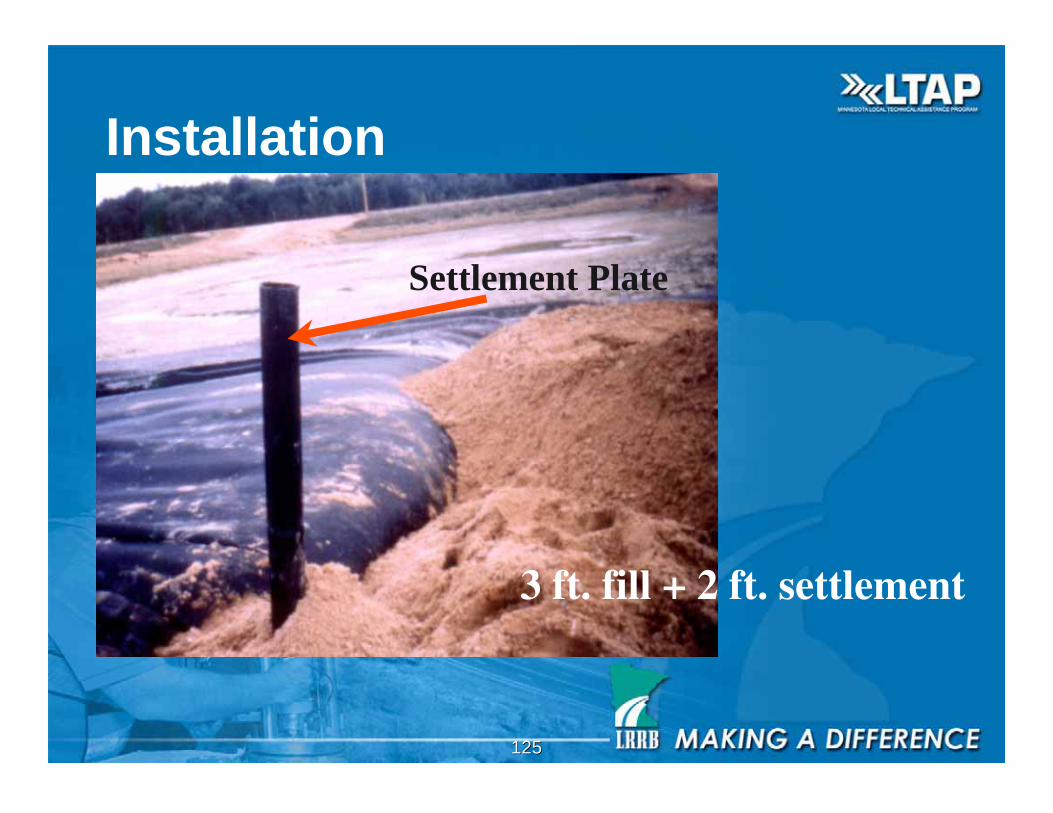
Installation
3 ft. fill + 2 ft. settlement
Settlement Plate
126126
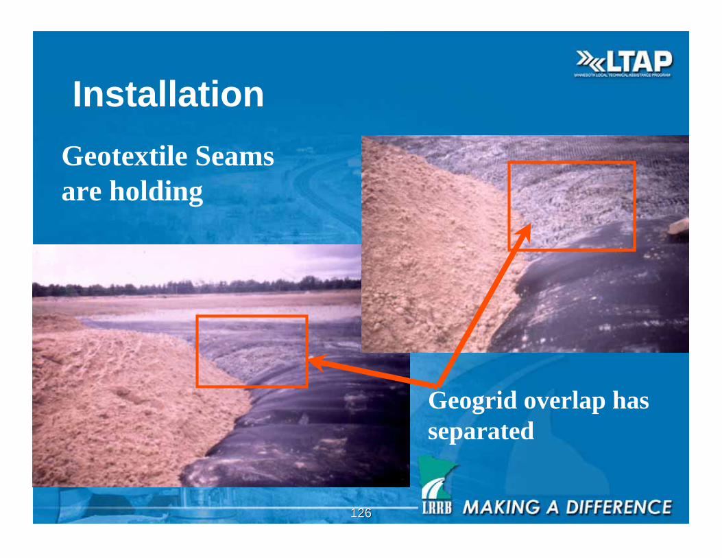
Installation
Geotextile Seams
are holding
Geogrid overlap has
separated
127127
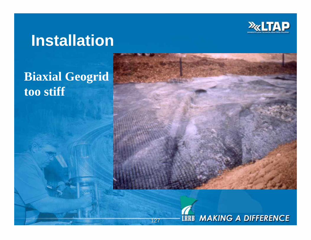
Installation
Biaxial Geogrid
too stiff
128128
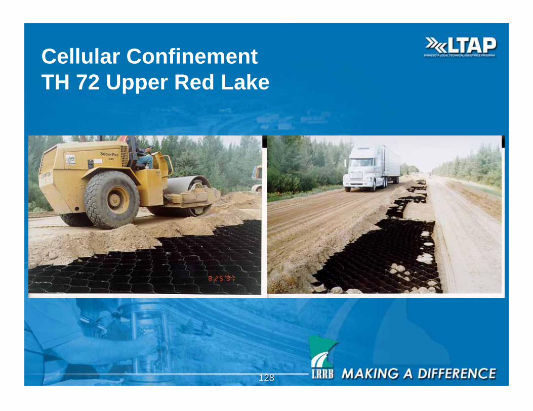
Cellular Confinement
TH 72 Upper Red Lake
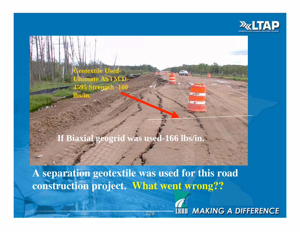
129129
A separation geotextile was used for this roadconstruction project. What went wrong??
Geotextile Used-
Ultimate ASTM D-
4595 Strength -100
lbs/in.
If Biaxial geogrid was used-166 lbs/in.
130130
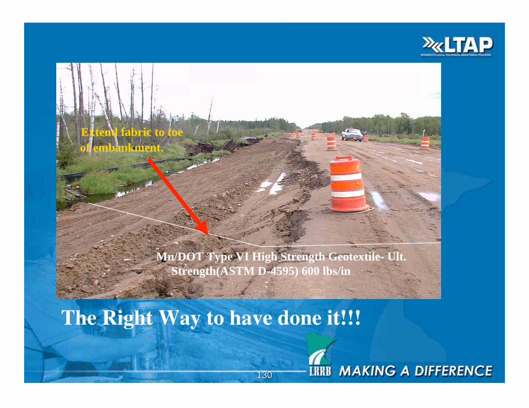
The Right Way to have done it!!!
Extend fabric to toe
of embankment.
Mn/DOT Type VI High Strength Geotextile- Ult.
Strength(ASTM D-4595) 600 lbs/in
131131
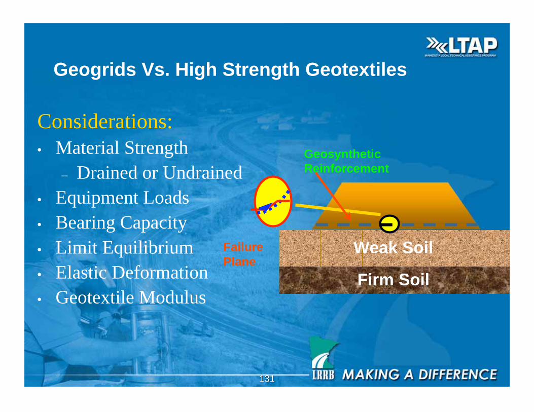
Geogrids Vs. High Strength Geotextiles
Considerations:
• Material Strength
– Drained or Undrained
• Equipment Loads
• Bearing Capacity
• Limit Equilibrium
• Elastic Deformation
• Geotextile Modulus
Weak Soil
Firm Soil
Failure
Plane
Geosynthetic
Reinforcement
132132
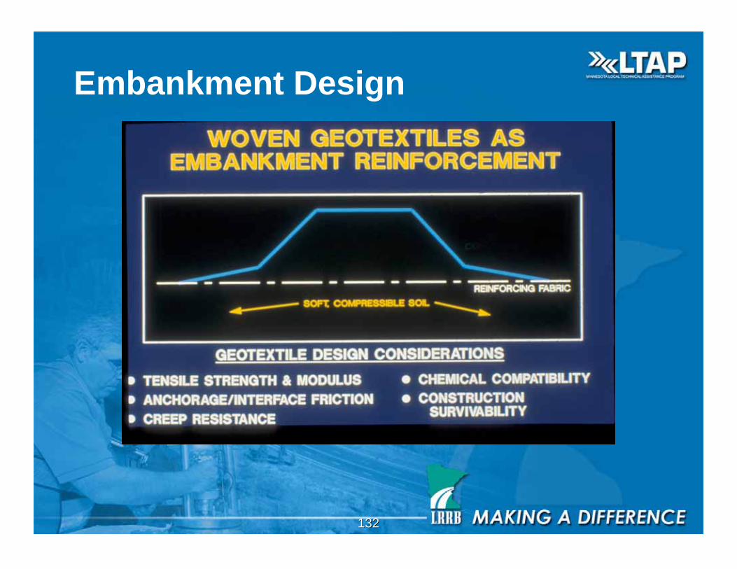
Embankment Design
133133
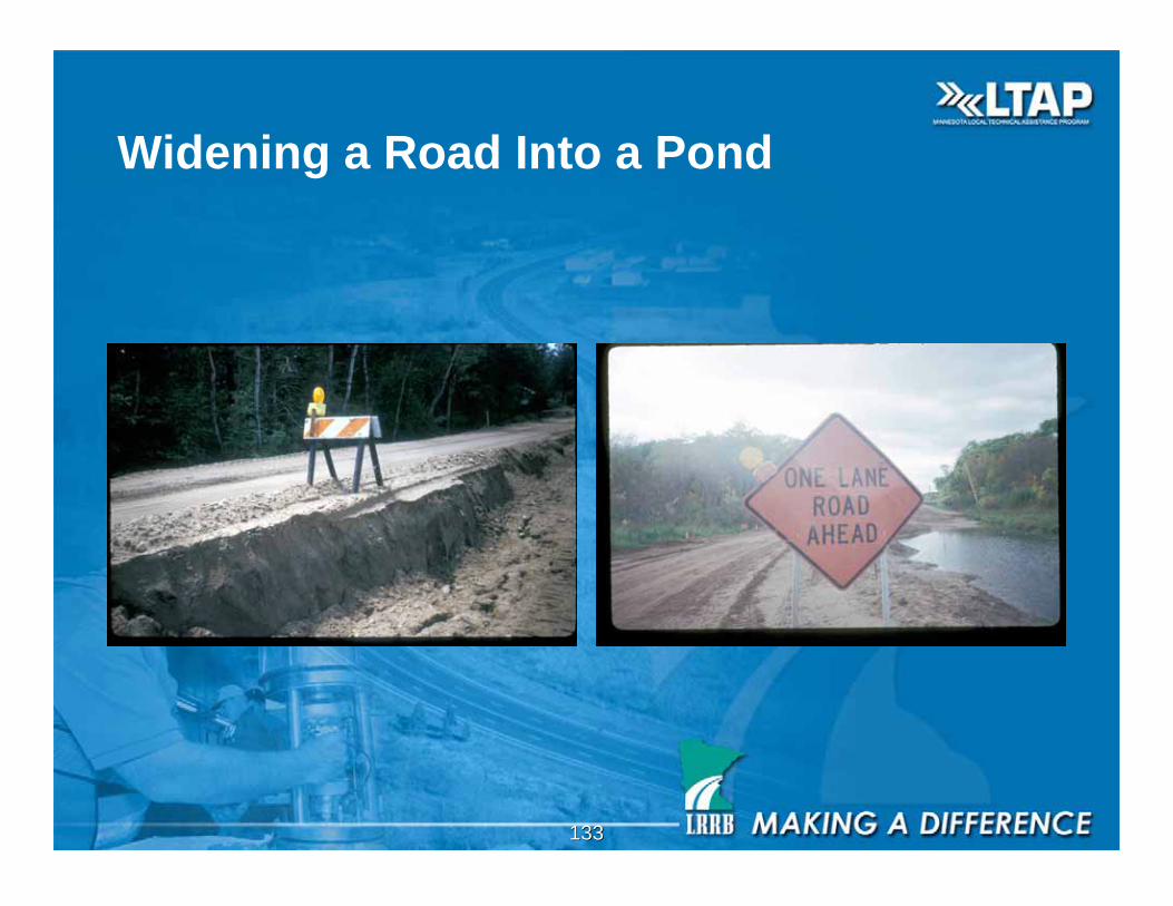
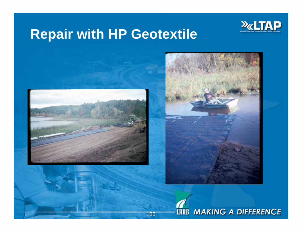
Widening a Road Into a Pond
134134
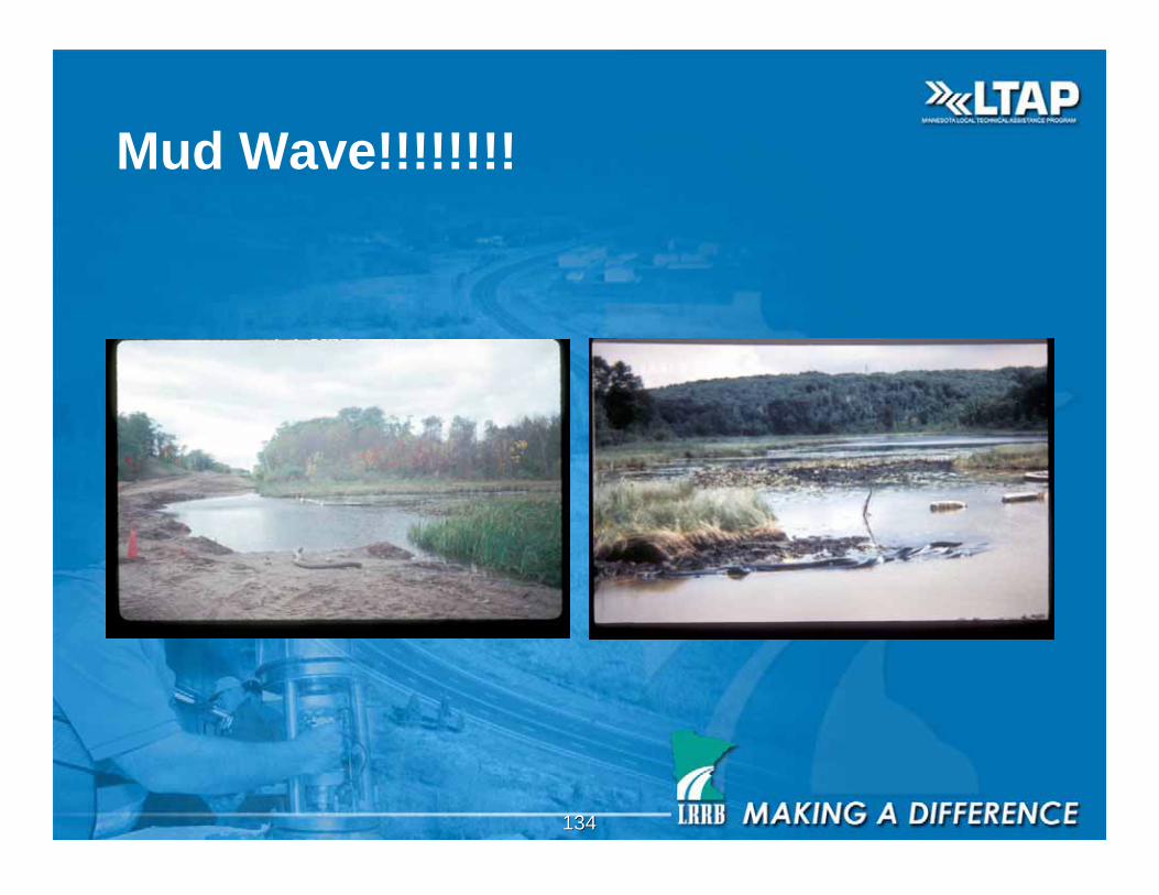
Mud Wave!!!!!!!!
135135
Repair with HP Geotextile
136136
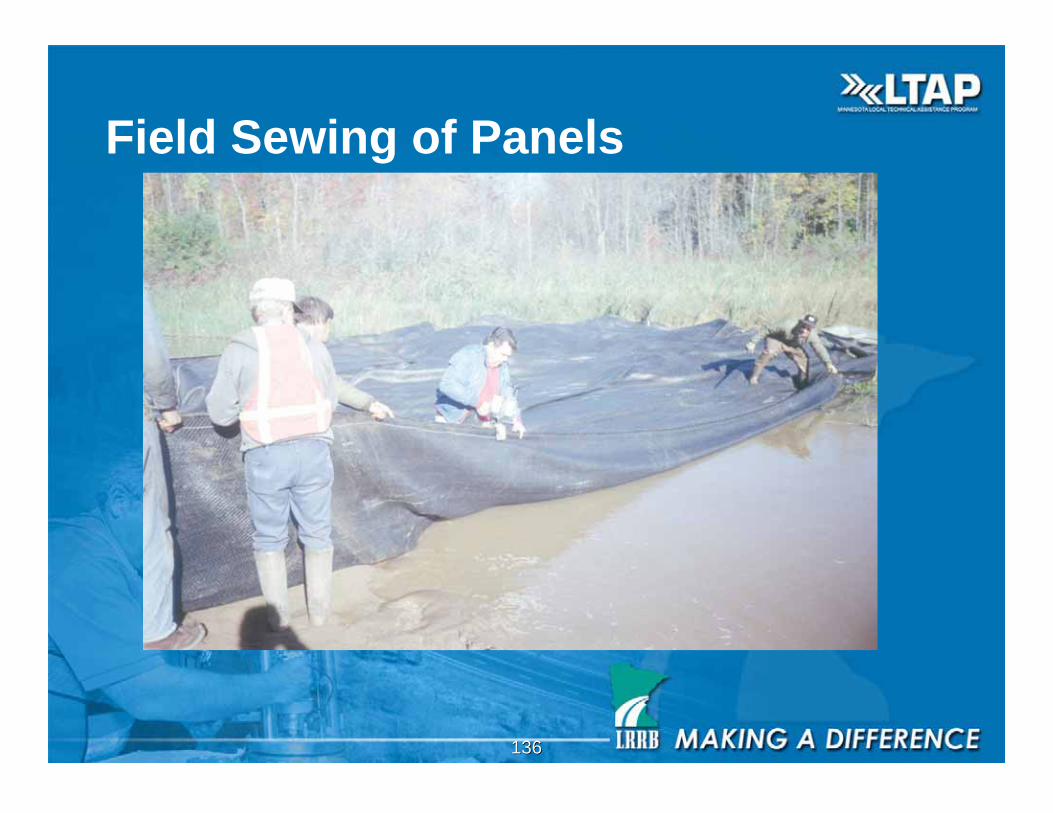
Field Sewing of Panels
137137
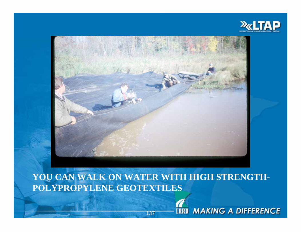
YOU CAN WALK ON WATER WITH HIGH STRENGTH-
POLYPROPYLENE GEOTEXTILES

138138
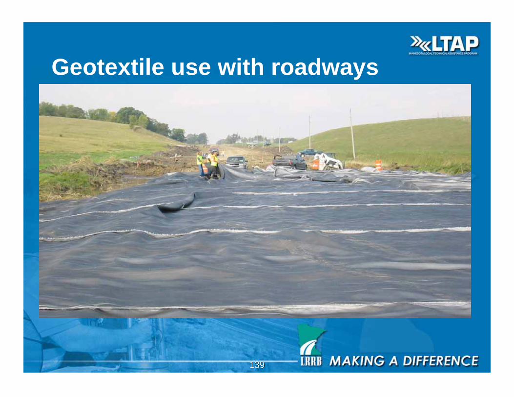
Geotextile use with roadways
139139
Geotextile use with roadways
140140
Sewing
141141
Sewing

142142
Take trees out prior to construction…
143143
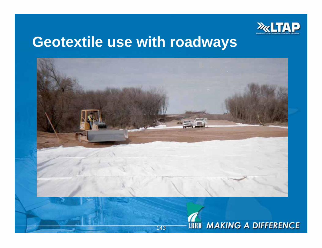
Geotextile use with roadways
144144
145145
Geosynthetics in overlays
• Advantages of use:
– Increase overlay and roadway life
– Decrease roadway maintenance costs
– Increase pavement serviceability
• Disadvantages of use:
– Will not help much if existing roadway is structurally
inadequate
– Will not solve water problems, subgrade problems, freeze-
thaw problems, or thermal cracking problems
From Berg, 1997, Chapter 6
146146
To Overlay or Not To Overlay
• Some controversy exists in using geosynthetics
in overlays
– May complicate mill and overlay operations
– If improperly installed, can move-in-place and
cause pavement cracks
• Future research needed in MN to resolve
issues of benefits / drawbacks
147147
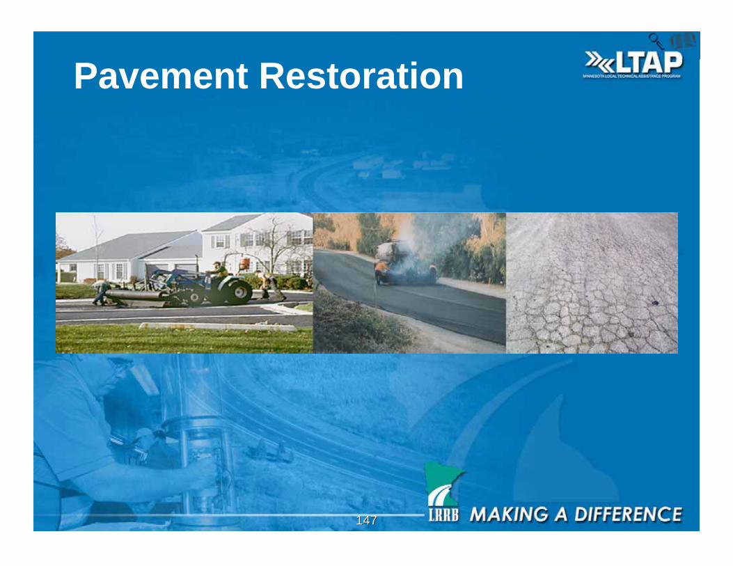
Pavement Restoration
148148
Pavement Restoration
The addition of a geosynthetic fabric onto existingpavement to form an impermeable membrane thatprevents the penetration of surface water throughthe pavement and also provides a stress relievinglayer which inhibits reflective crack growth.
149149
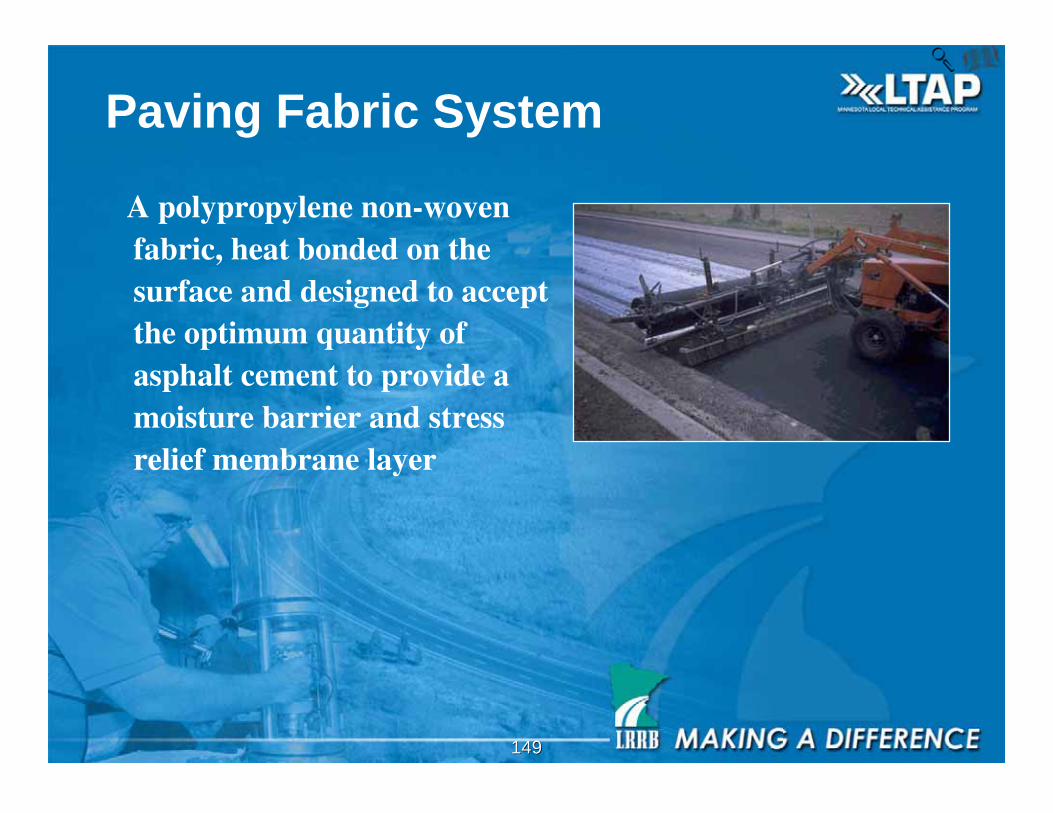
Paving Fabric System
A polypropylene non-wovenfabric, heat bonded on thesurface and designed to acceptthe optimum quantity ofasphalt cement to provide amoisture barrier and stressrelief membrane layer
150150
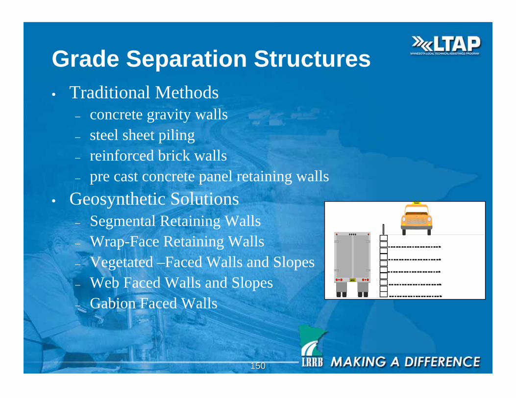
Grade Separation Structures
• Traditional Methods– concrete gravity walls
– steel sheet piling
– reinforced brick walls
– pre cast concrete panel retaining walls
• Geosynthetic Solutions– Segmental Retaining Walls
– Wrap-Face Retaining Walls
– Vegetated –Faced Walls and Slopes
– Web Faced Walls and Slopes
– Gabion Faced Walls
151151
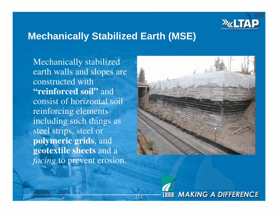
Mechanically Stabilized Earth (MSE)
Mechanically stabilizedearth walls and slopes areconstructed with“reinforced soil” andconsist of horizontal soilreinforcing elementsincluding such things assteel strips, steel orpolymeric grids, andgeotextile sheets and afacing to prevent erosion.
152152
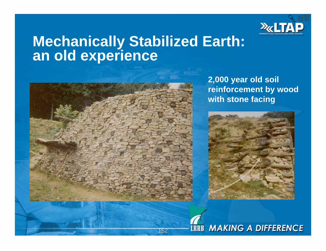
Mechanically Stabilized Earth:an old experience
2,000 year old soil
reinforcement by wood
with stone facing
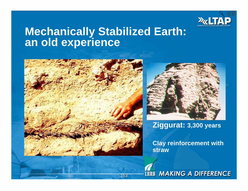
153153
Ziggurat: 3,300 years
Clay reinforcement withstraw
Mechanically Stabilized Earth:an old experience
154154
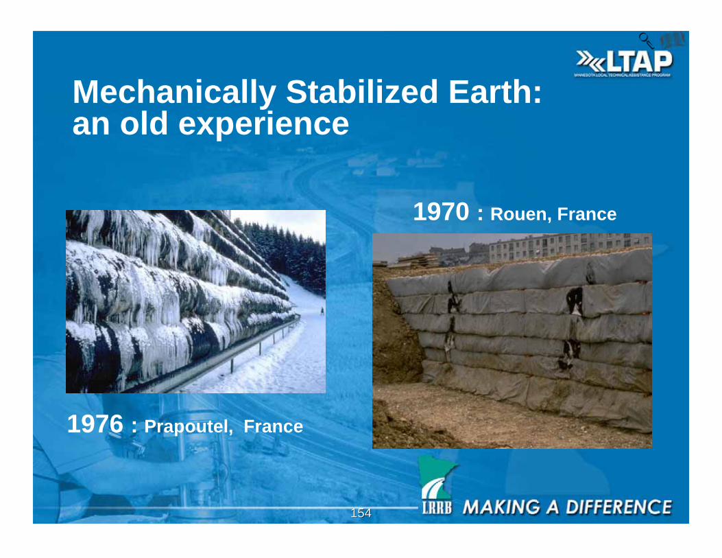
1970 : Rouen, France
1976 : Prapoutel, France
Mechanically Stabilized Earth:an old experience
155155
Mechanically Stabilized Earth (MSE)
• Mechanically StabilizedEarth Walls (MSEW)
• Reinforced Soil Slopes(RSS)

156156
• Mechanically stabilized earth walls (MSEW)
• A face inclination greaterthan, or equal, to 70degrees from horizontal
• Includes multiple planarlayers of man-madereinforcing elements thatact as reinforcement forsoils placed as infillmaterials.
Mechanically Stabilized Earth (MSE)
157157
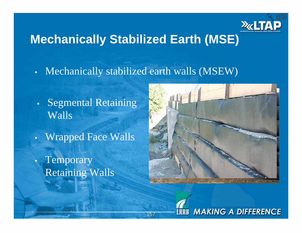
Mechanically Stabilized Earth (MSE)
• Mechanically stabilized earth walls (MSEW)
• Segmental Retaining
Walls
• Wrapped Face Walls
• Temporary
Retaining Walls
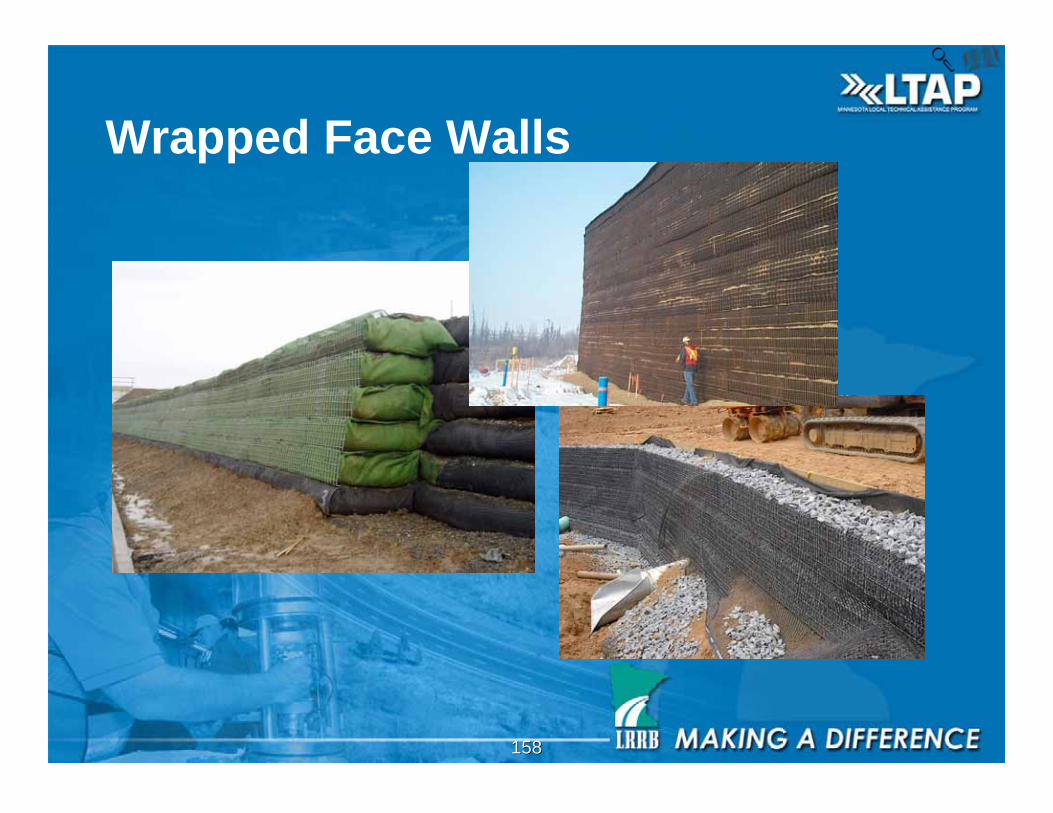
158158
Wrapped Face Walls
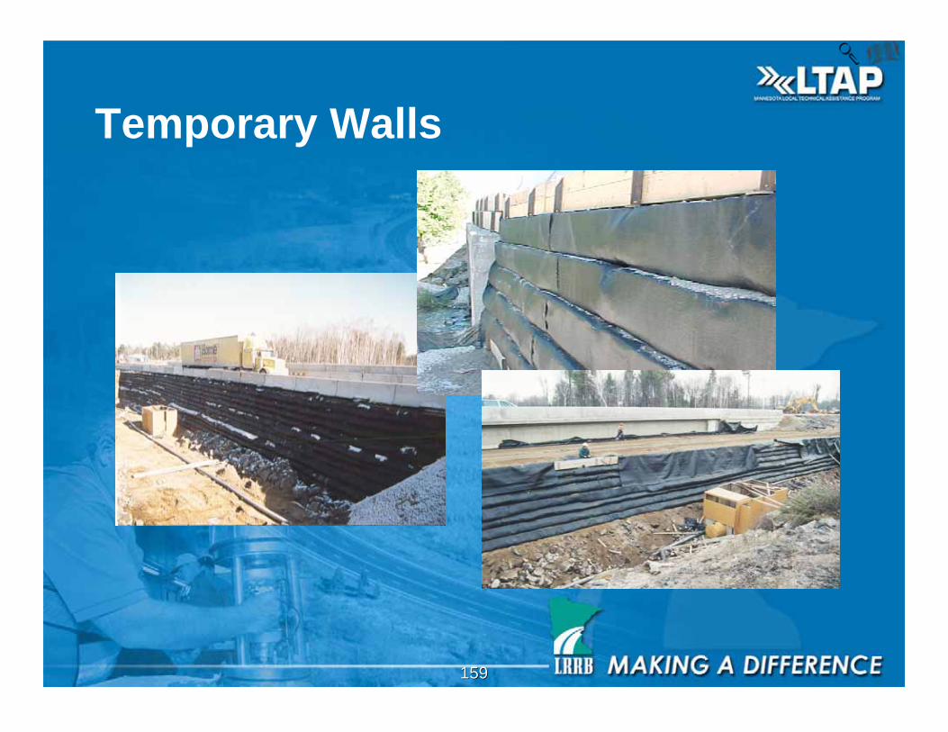
159159
Temporary Walls
160160
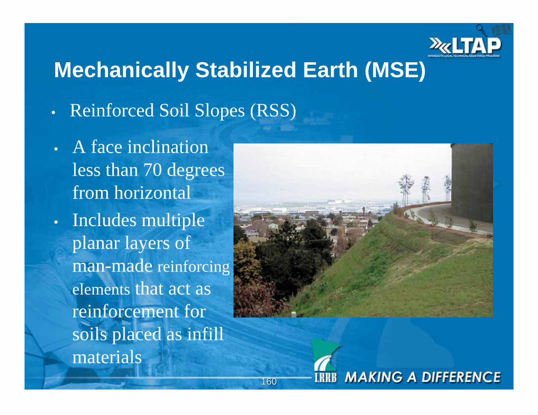
Mechanically Stabilized Earth (MSE)
• Reinforced Soil Slopes (RSS)
• A face inclination
less than 70 degrees
from horizontal
• Includes multiple
planar layers of
man-made reinforcing
elements that act as
reinforcement for
soils placed as infill
materials
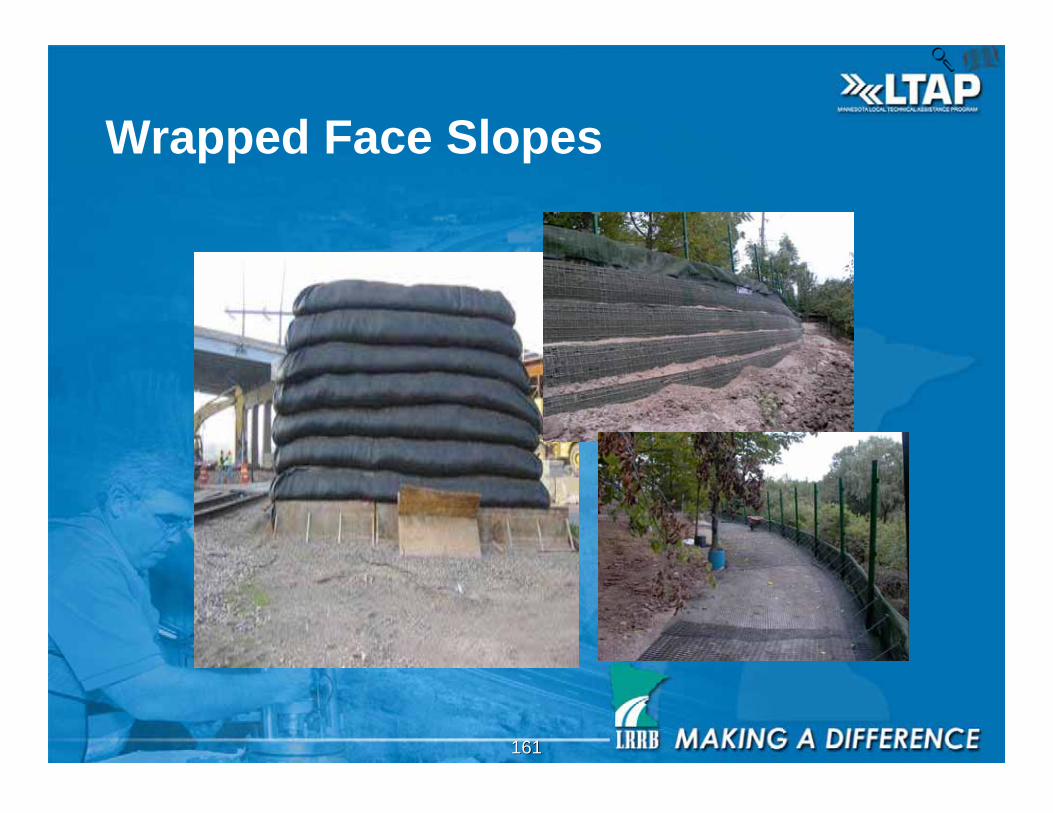
161161
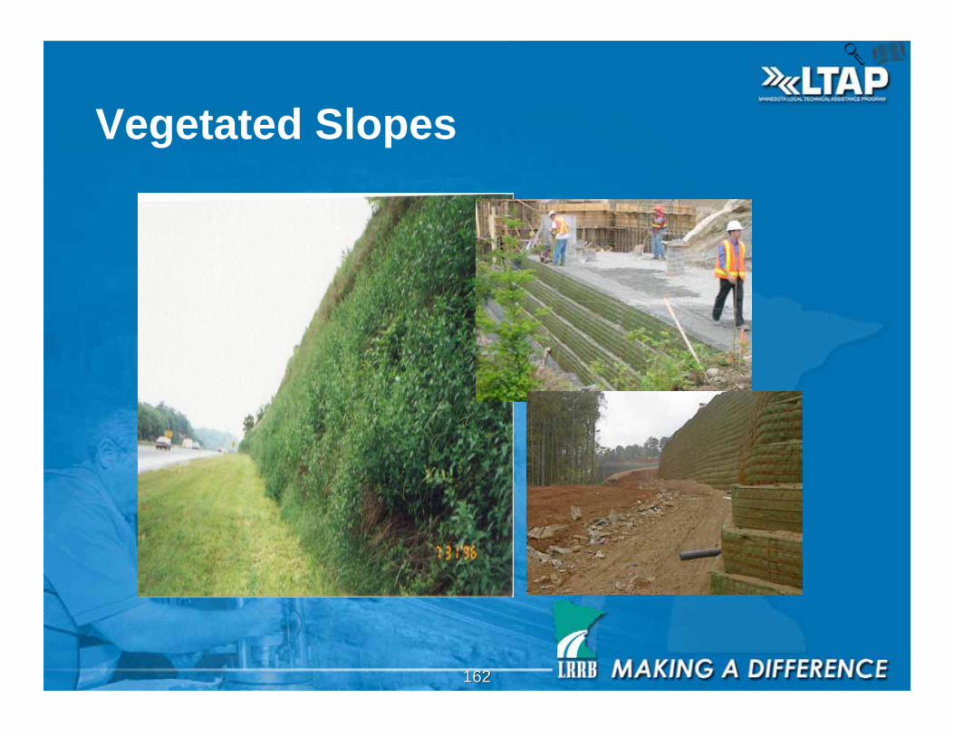
Wrapped Face Slopes
162162
Vegetated Slopes
163163
Mn/DOT Design Standards
• MBW (Modular Block Wall)
• RSS (Reinforced Soil Slope)
164164
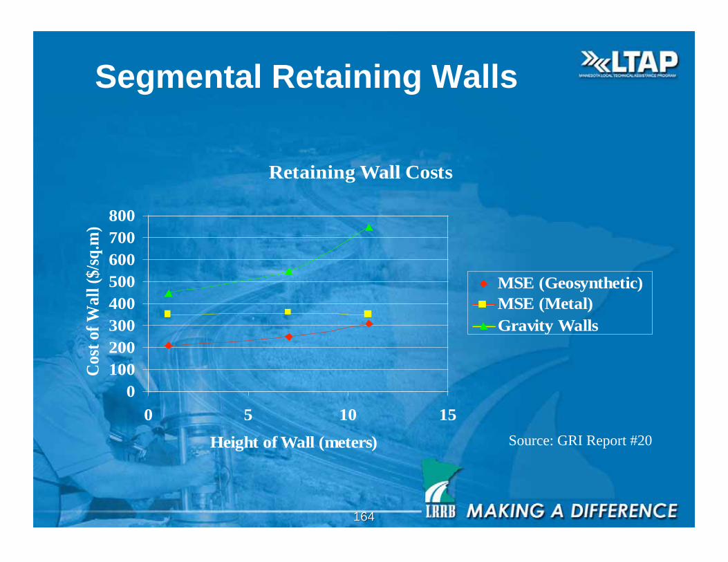
Retaining Wall Costs
0
100
200
300
400
500
600
700
800
0 5 10 15
Height of Wall (meters)
Co
st o
f W
all
($
/sq
.m)
MSE (Geosynthetic)
MSE (Metal)
Gravity Walls
Segmental Retaining Walls
Source: GRI Report #20
165165

166166
Engineering
Properly engineered and installed RSS are works of art!
167167
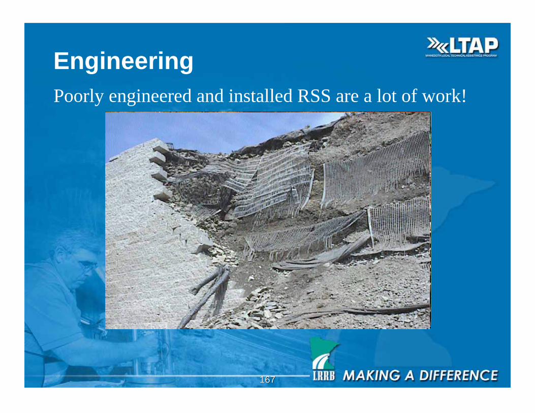
Engineering
Poorly engineered and installed RSS are a lot of work!
168168
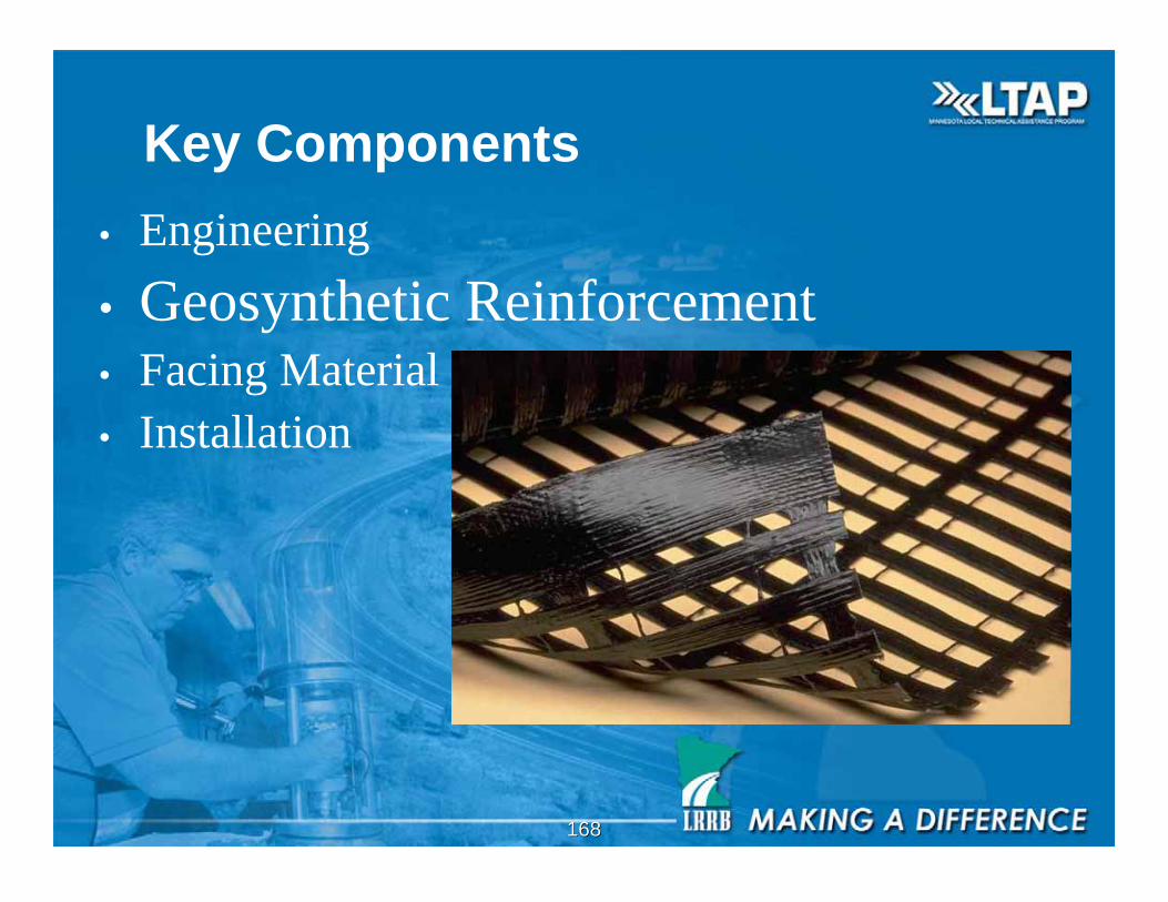
Key Components
• Engineering
• Geosynthetic Reinforcement• Facing Material
• Installation
169169
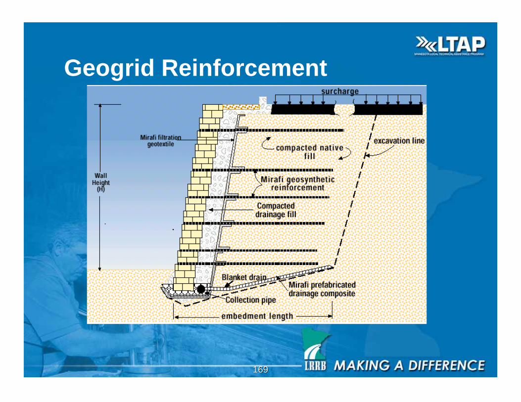
Geogrid Reinforcement
170170
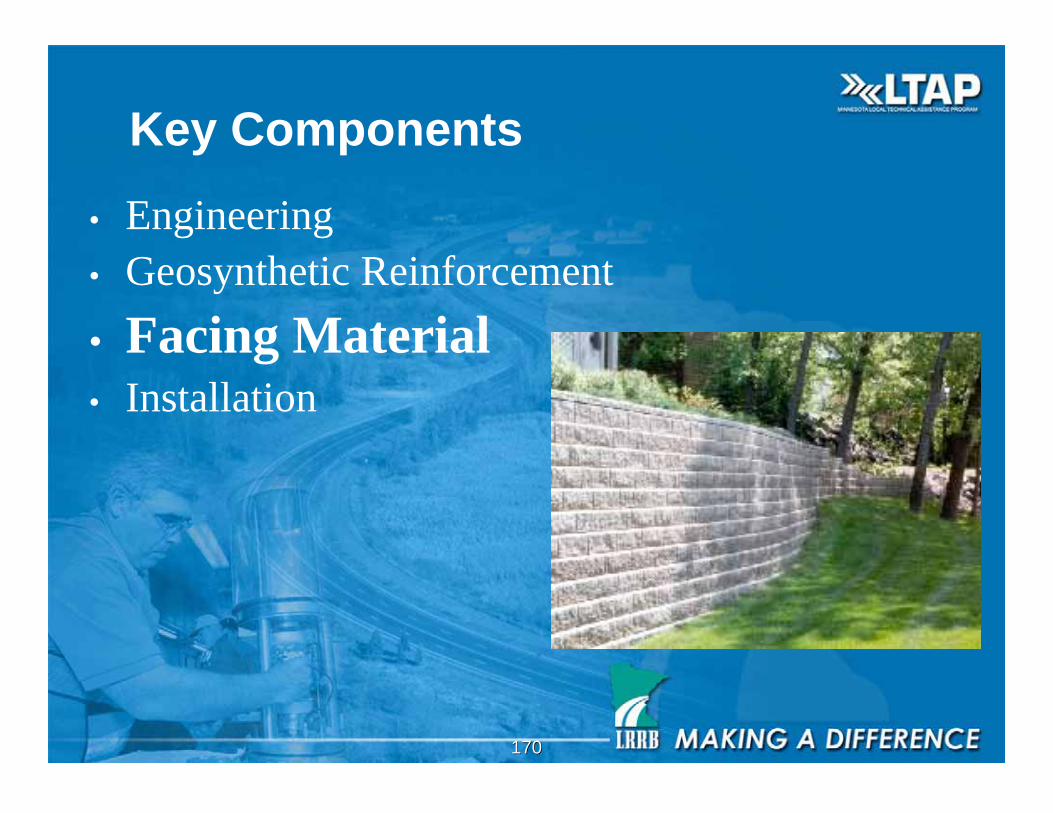
Key Components
• Engineering
• Geosynthetic Reinforcement
• Facing Material• Installation
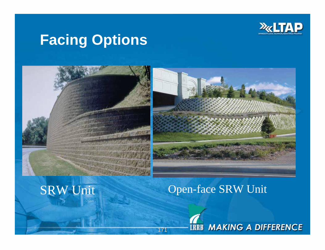
171171
Facing Options
SRW Unit Open-face SRW Unit
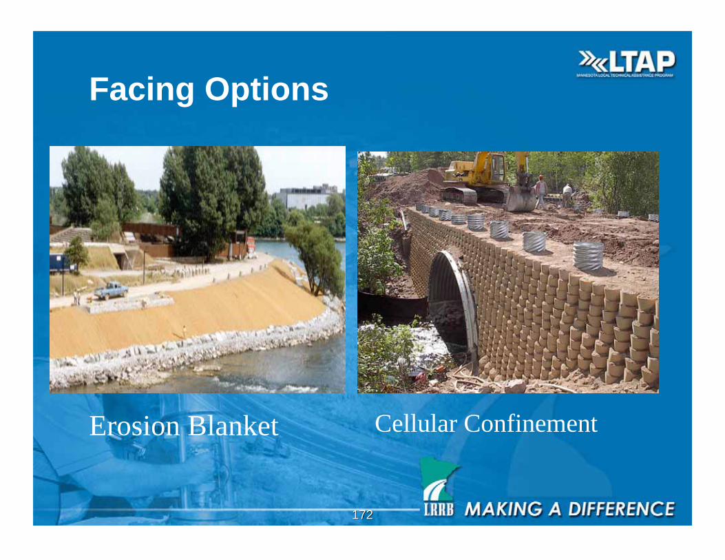
172172
Facing Options
Erosion Blanket Cellular Confinement
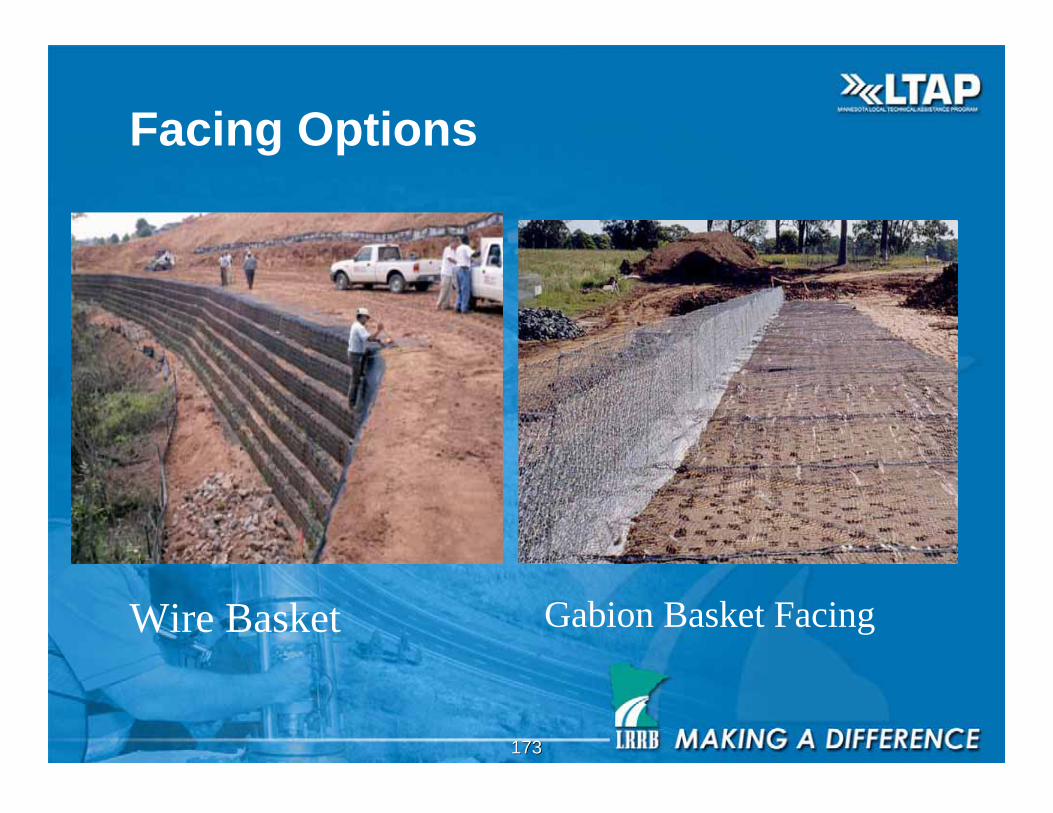
173173
Facing Options
Wire Basket Gabion Basket Facing
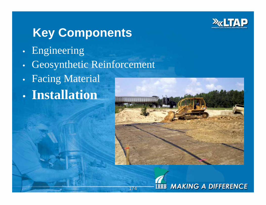
174174
Key Components
• Engineering
• Geosynthetic Reinforcement
• Facing Material
• Installation
175175
• Make sure engineered structures are engineered
• Make sure the correct geogrid is placed at theindicated location in the wall
• Make sure the embedment length of the geogrid iscorrect
• Make sure the orientation of the geogrid is correct
• Most geogrids should be rolled perpendicular to theslope/wall face
• Make sure the geogrid is tensioned before placing soil
• Drainage!, Drainage!, Drainage!
• Make sure facing is stable
Installation Issues
176176
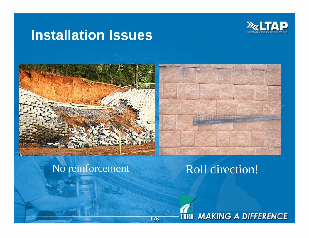
Installation Issues
Roll direction!No reinforcement
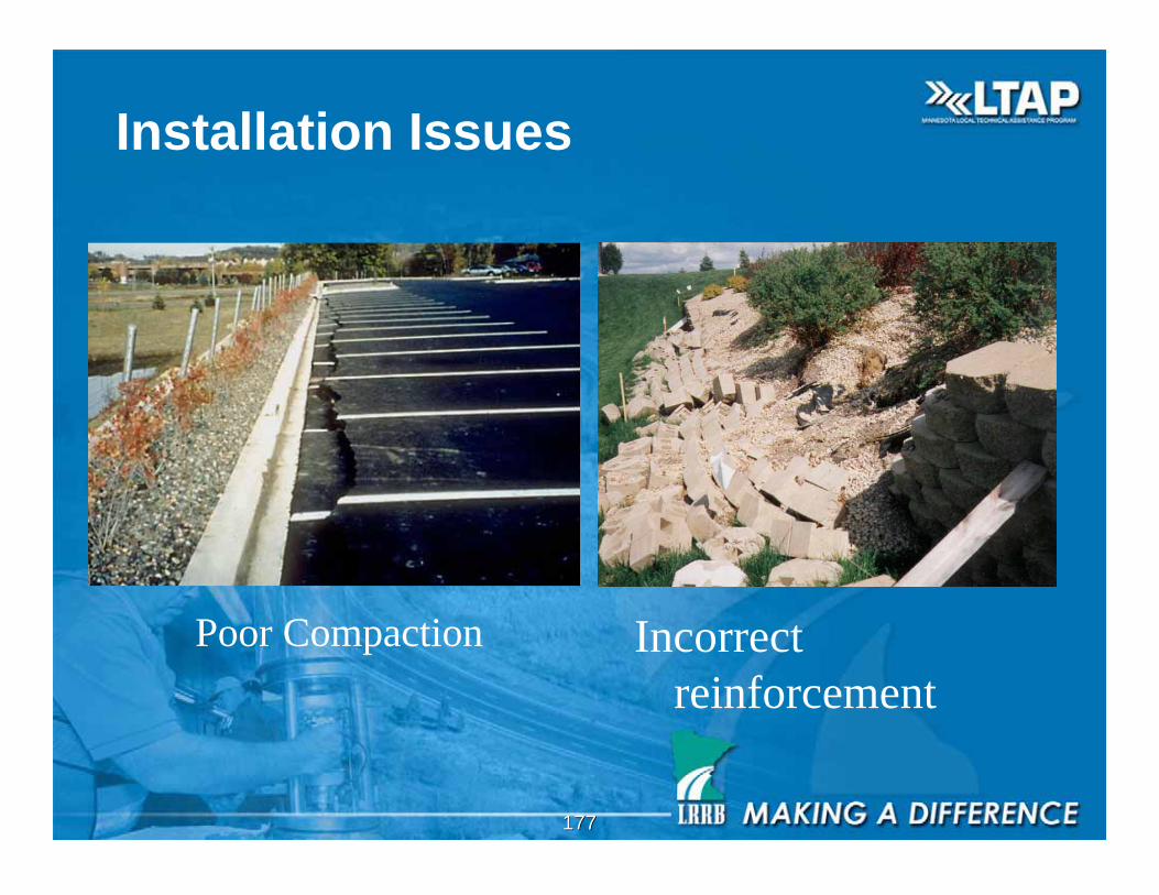
177177
Incorrect
reinforcement
Poor Compaction
Installation Issues
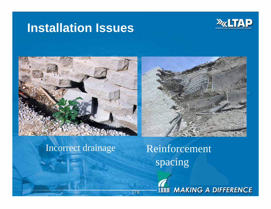
178178
Reinforcement
spacing
Incorrect drainage
Installation Issues
179179
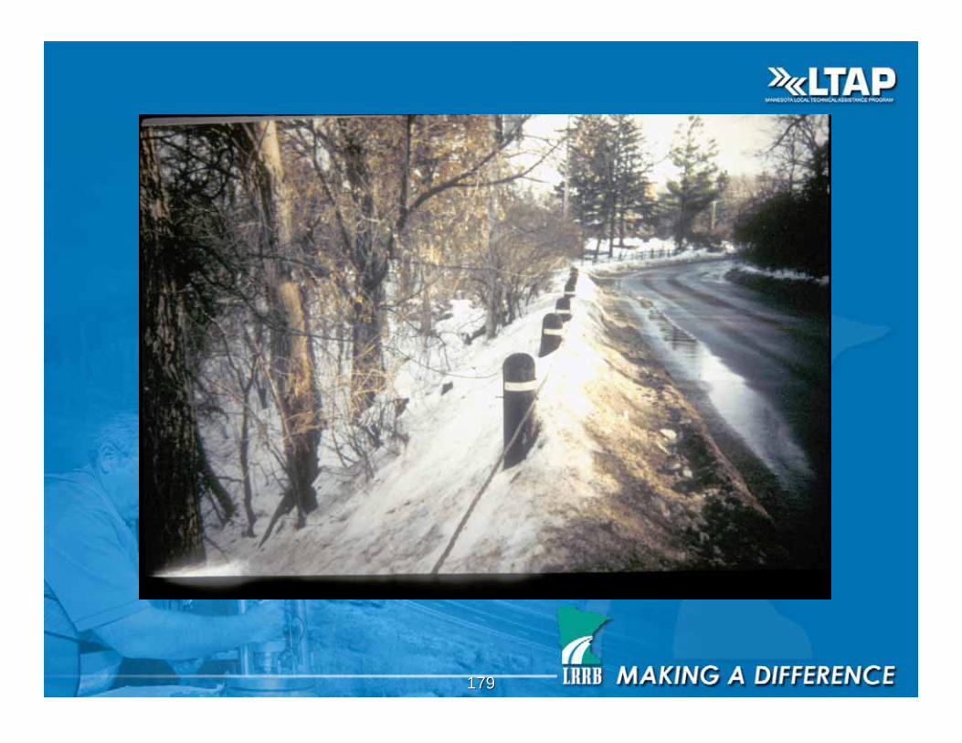
180180
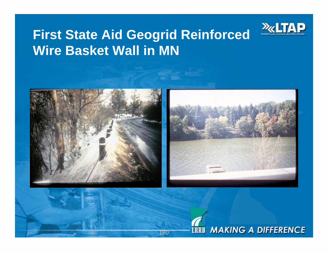
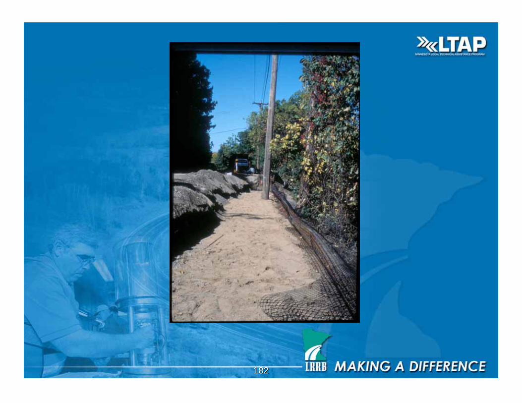
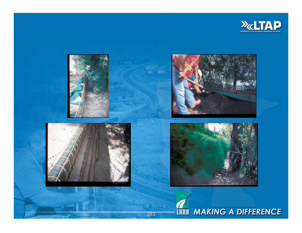
First State Aid Geogrid Reinforced
Wire Basket Wall in MN

181181
Edina, MN
182182
183183

184184
Natural Look-View from Interlachen
Golf Club
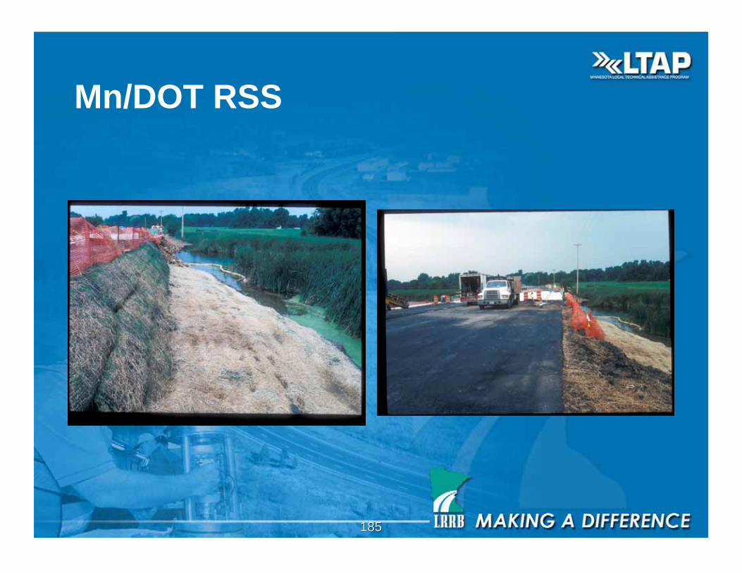
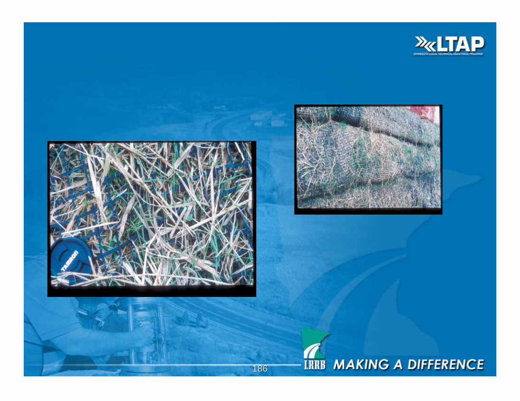
185185
Mn/DOT RSS
186186

187187
Designed Reinforced Slope
and Wire Basket Wall
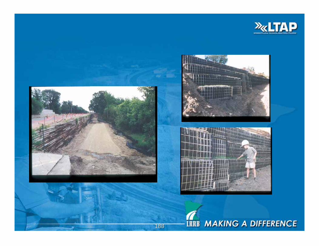
188188
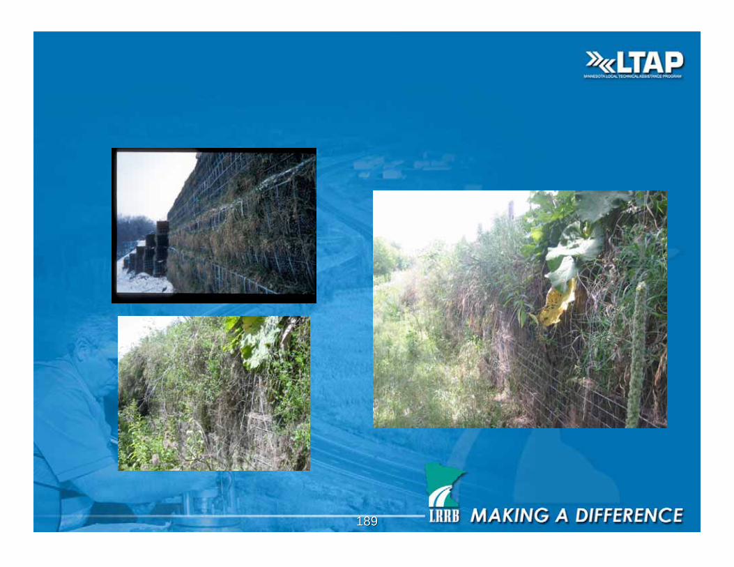
189189

190190
W 78th Street Edina, MN
191191
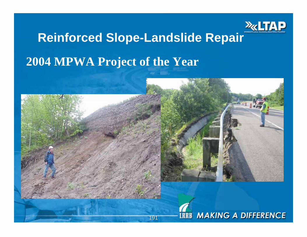
Reinforced Slope-Landslide Repair
2004 MPWA Project of the Year
192192
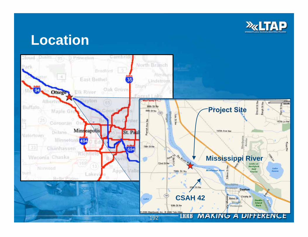
Location
Project Site
Mississippi River
CSAH 42
193193
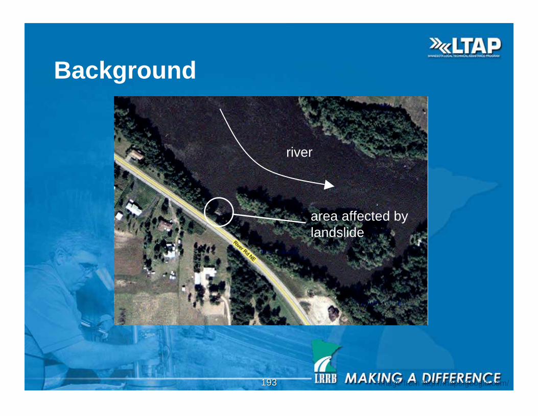
Background
river
area affected by
landslide
*image from http://maps.google.com/
194194
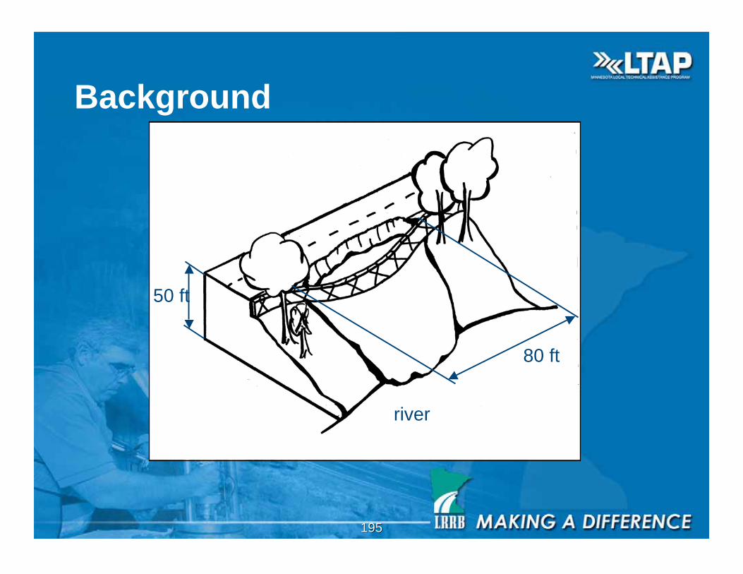
195195
Background
80 ft50 ft
river
80 ft
196196
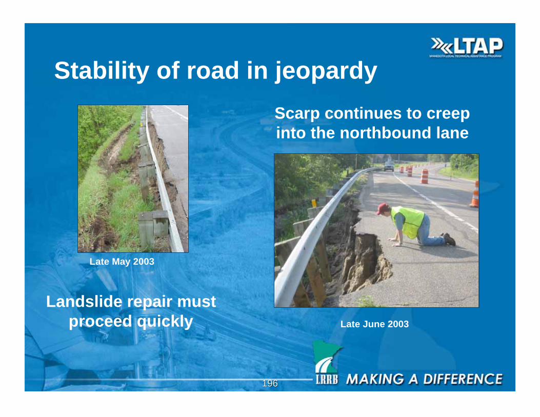
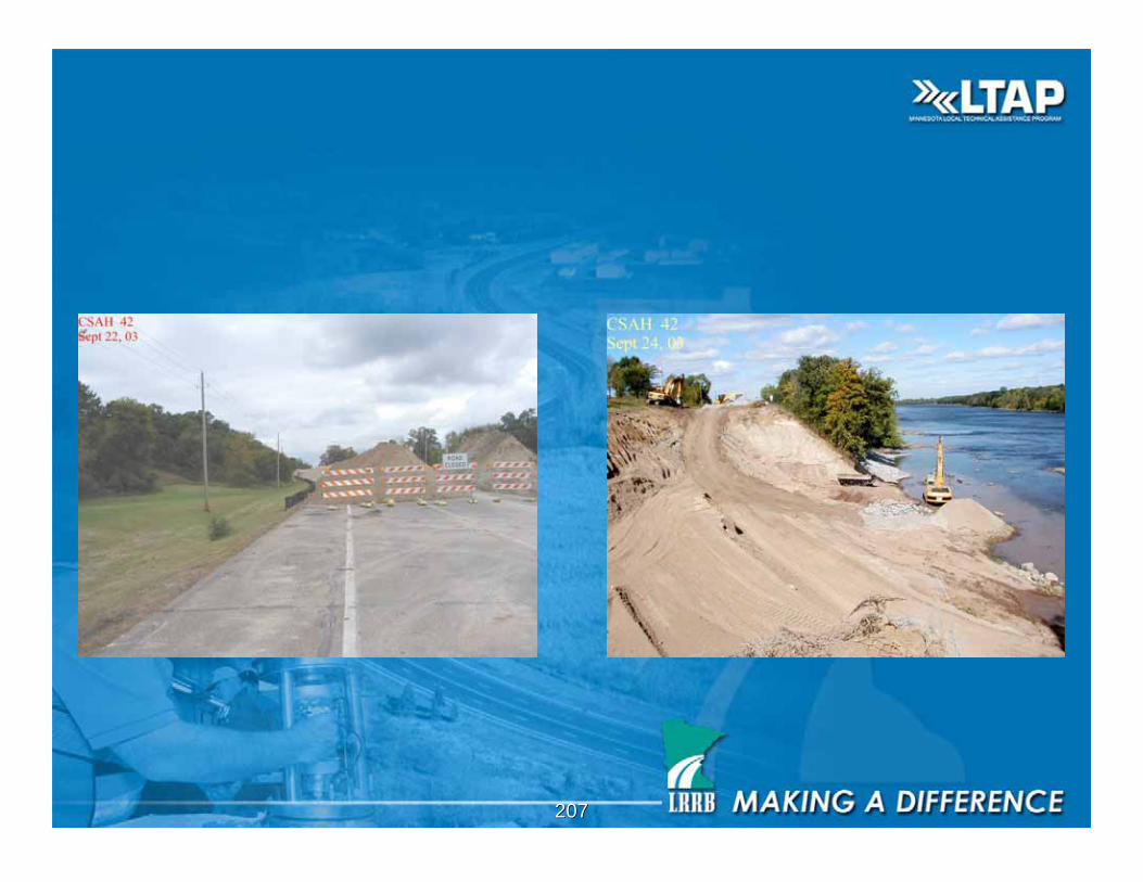
Stability of road in jeopardy
Late May 2003
Late June 2003
Scarp continues to creep
into the northbound lane
Landslide repair must
proceed quickly
197197
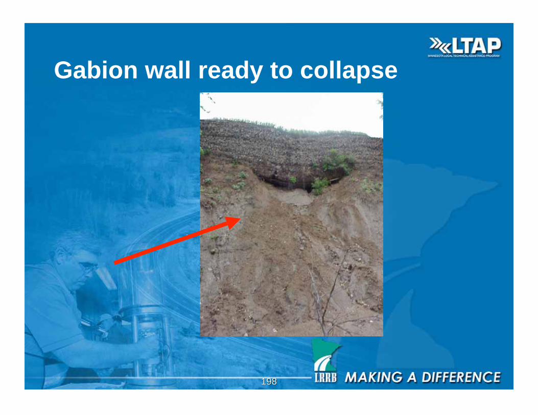
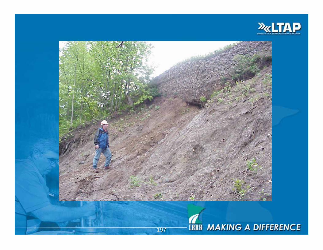
198198
Gabion wall ready to collapse
199199
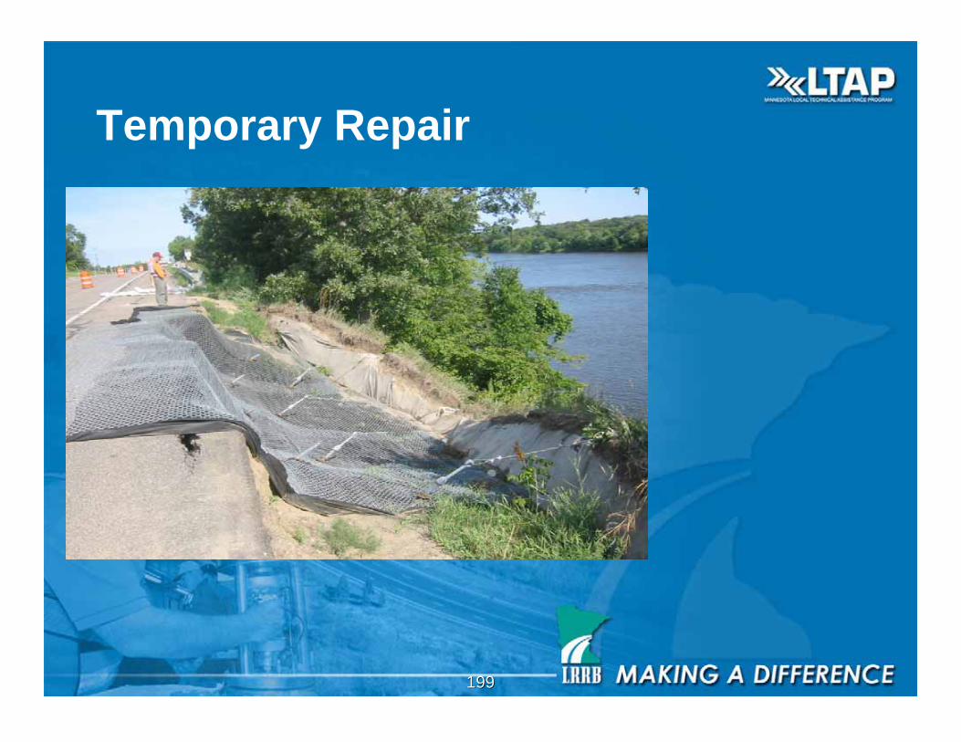
Temporary Repair
200200
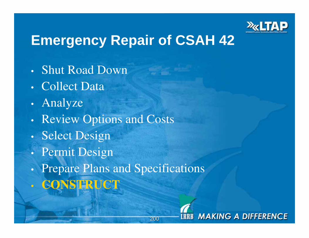
Emergency Repair of CSAH 42
• Shut Road Down• Collect Data• Analyze• Review Options and Costs• Select Design• Permit Design• Prepare Plans and Specifications• CONSTRUCT
201201
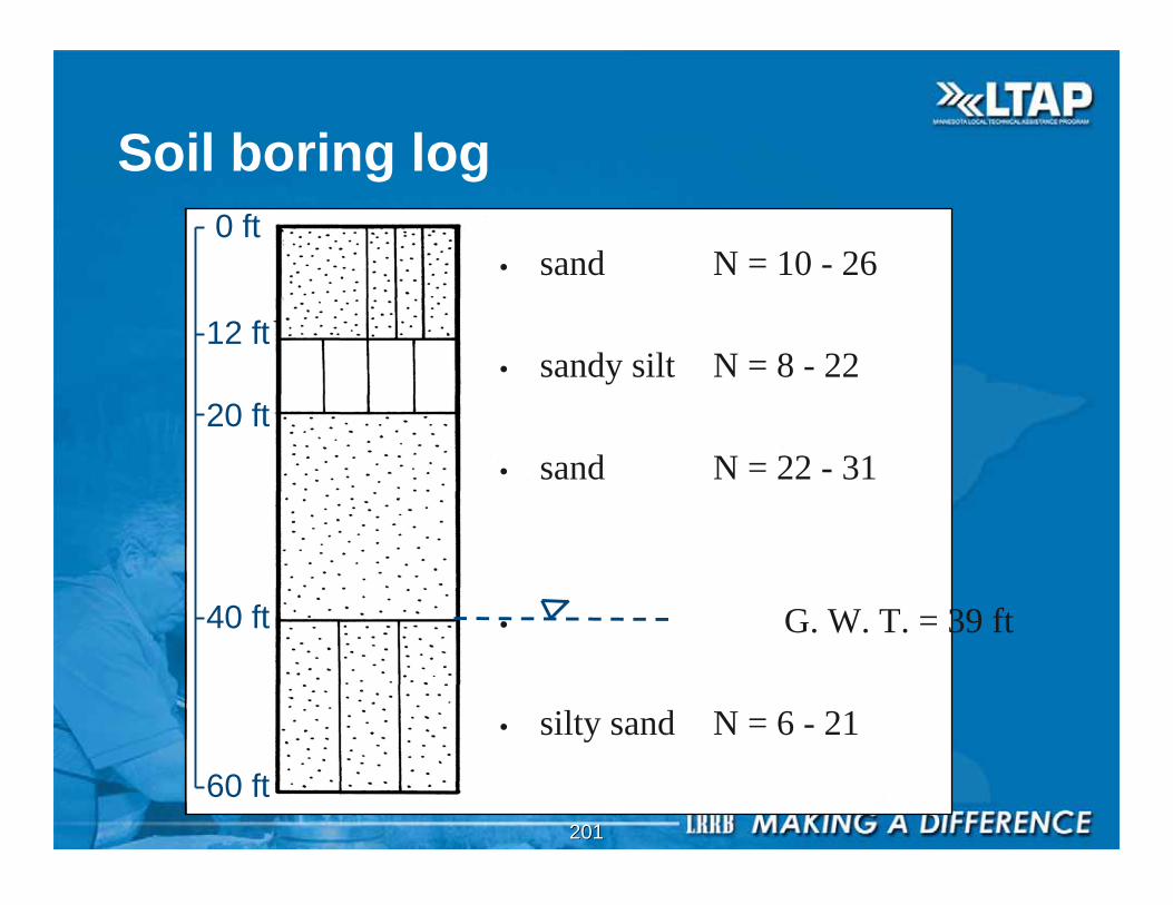
0 ft
12 ft
20 ft
40 ft
60 ft
Soil boring log
• sand N = 10 - 26
• sandy silt N = 8 - 22
• sand N = 22 - 31
• G. W. T. = 39 ft
• silty sand N = 6 - 21
202202
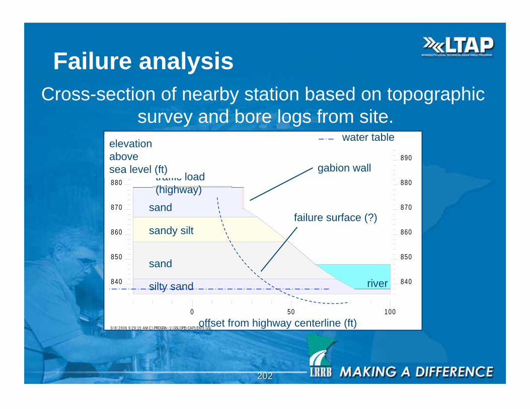
Failure analysis
840 840
850 850
860 860
870 870
880 880
890 890
3/8/2006 9:29:15 AM C:\PROGRA~1\GSLOPE\CAP1EXP3.GSL
0 50 100
river
traffic load
(highway)
gabion wall
sand
sandy silt
sand
silty sand
offset from highway centerline (ft)
elevation
above
sea level (ft)
Cross-section of nearby station based on topographic
survey and bore logs from site.
failure surface (?)
water table

203203
Results of analysis
840 840
850 850
860 860
870 870
0 50 100
F = 1.007
= 120 pcf
= 125 pcf
= 120 pcf
= 125 pcf
offset from highway centerline (ft)
elevation above
sea level (ft)
failure surface
100 yr flood
= 35
= 32
= 35
= 30
c = 0
c = 50 psf
c = 0
c = 0
groundwater elevation (858 ft)
Critical scenario: Rapid drawdown
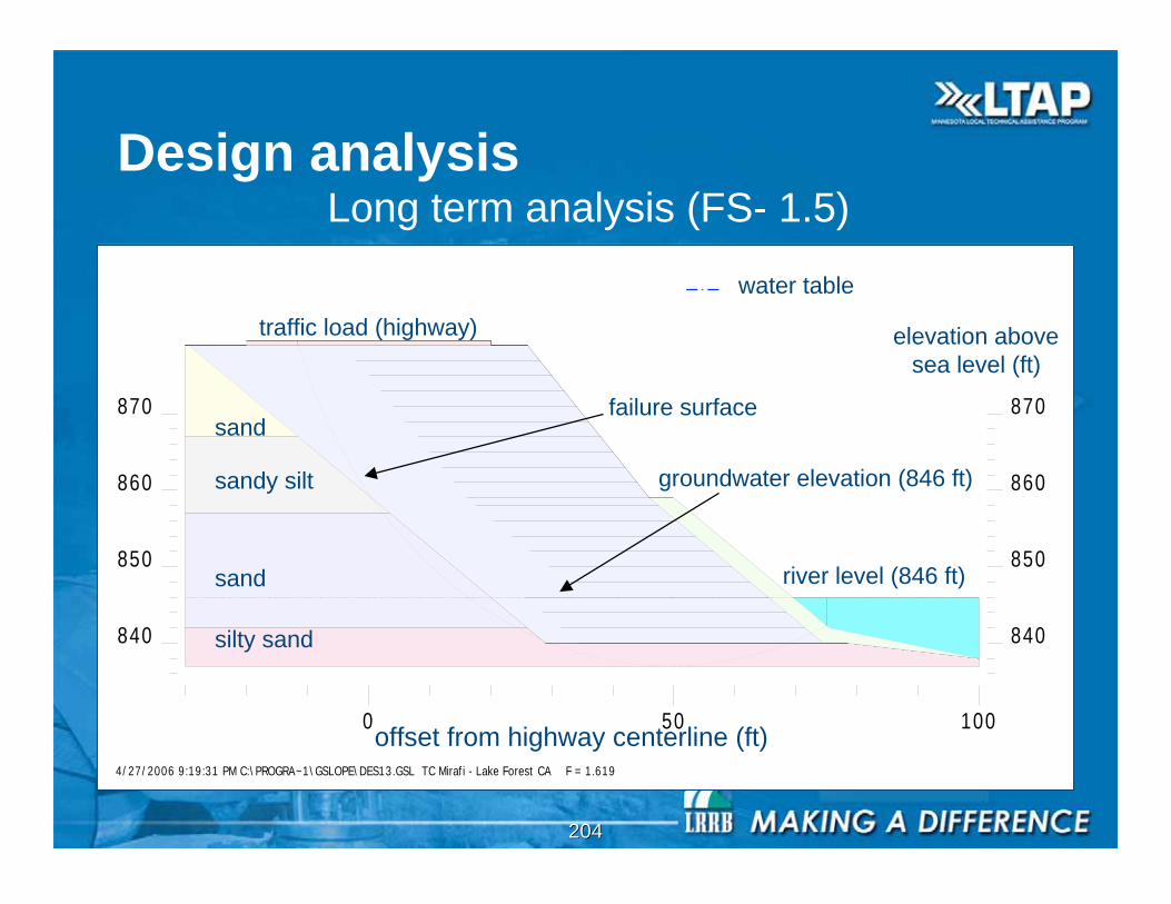
204204
840 840
850 850
860 860
870 870
4/27/2006 9:19:31 PM C:\PROGRA~1\GSLOPE\DES13.GSL TC Mirafi - Lake Forest CA F = 1.619
0 50 100
Design analysis
river level (846 ft)
traffic load (highway)
sand
sandy silt
sand
silty sand
offset from highway centerline (ft)
elevation above
sea level (ft)
water table
Long term analysis (FS- 1.5)
failure surface
groundwater elevation (846 ft)
205205
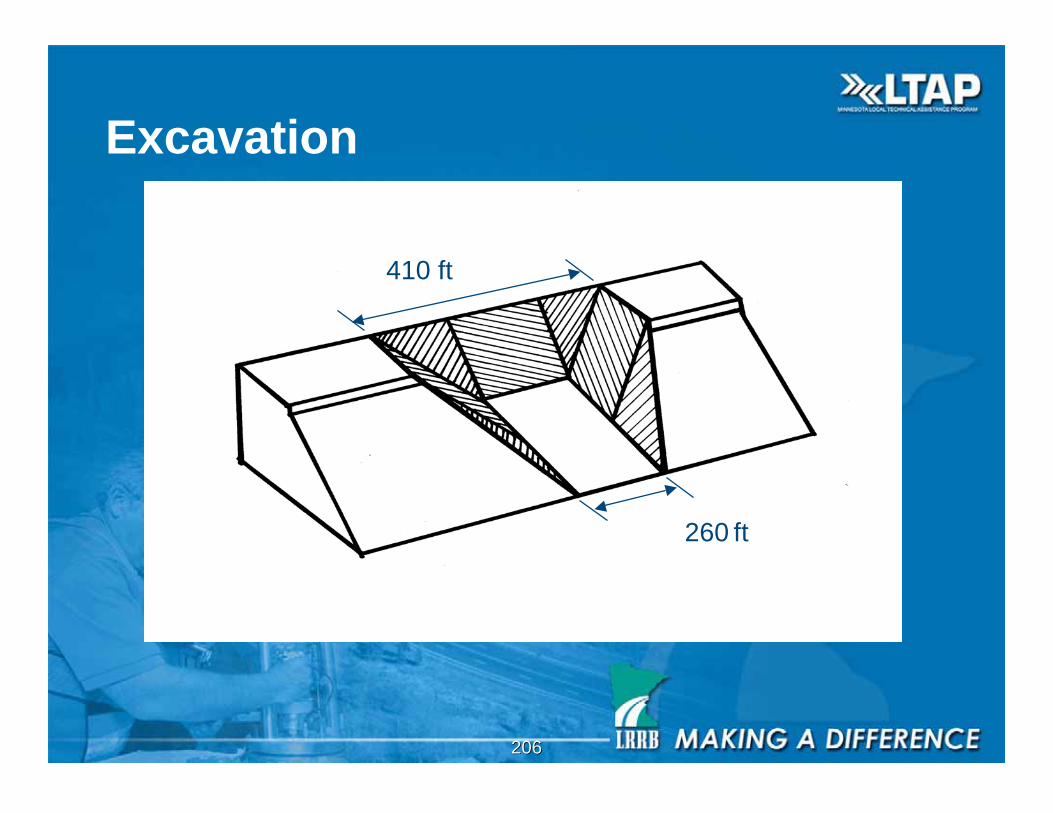
206206
Excavation
260 ft
410 ft
207207
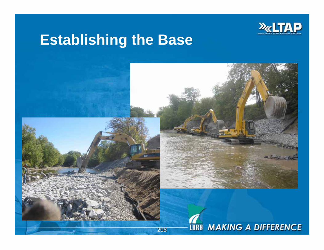
208208
Establishing the Base
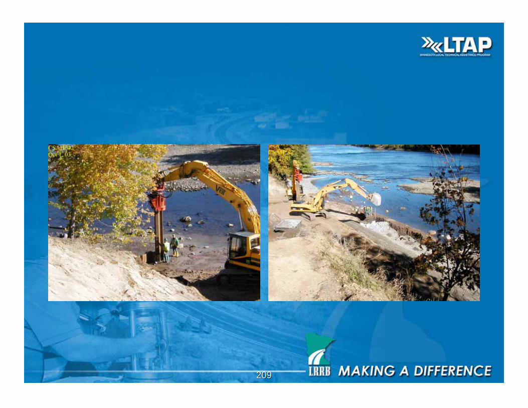
209209
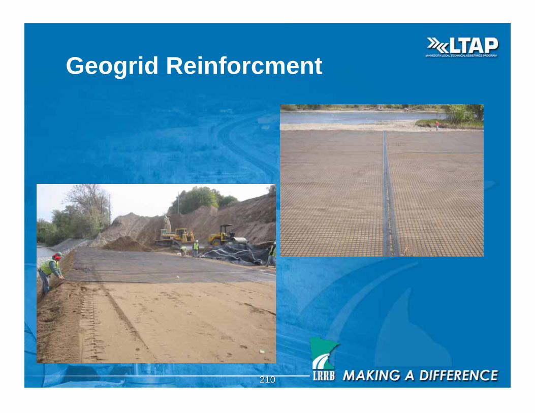
210210
Geogrid Reinforcment
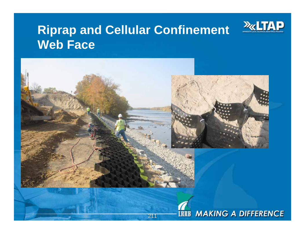
211211
Riprap and Cellular Confinement
Web Face

212212
Steve
Thank
you
Recommended