MLHM
MLHP
MLHR
MLHH
MLHM
MLHP
MLHR
MLHH
MLHM
MLHP
MLHR
MLHH
MLHM
MLHP
MLHR
MLHH

SPOOL VALVE HYDRAULIC MOTORS
CONTENTS
Page
Hydraulic Motors Series MLHM .................................................................................... 4
Hydraulic Motors Series MLHP ................................................................................... 13
Application Calculations ............................................................................................. 106
•
•
•
•
•
•
•
•
Hydraulic Motors Series MLHR ................................................................................... 33
Hydraulic Motors Series MLHPL ................................................................................. 44
Hydraulic Motors Series MLHRL ................................................................................. 49
Hydraulic Motors Series HP ....................................................................................... 53
Hydraulic Motors Series HR ....................................................................................... 62
Hydraulic Motors Series MLHRW .............................................................................. 67
Hydraulic Motors Series MLHH .................................................................................. 77
Hydraulic Motors Series HW ..................................................................................... 85
Motor Special Features............................................................................................... 103
Motors with Speed Sensor........................................................................................... 104
.
•
•
•
•
•
“M+S HYDRAULIC” can accept no responsibility for possible errors in catalogues, brochures and other printed material.“M+S HYDRAULIC” reserves the right to alter its products without notice. This also applies to products already on order provided that suchalterations can be made without subsequential changes being necessary in specifications already agreed.

SPOOL VALVE HYDRAULIC MOTORS
3
DISTRIBUTOR VALVEMLHM, MLHP, MLHR, MLHH, MLHPL, MLHRL, HP, HR, MLHRW, HW series motors have spool valve: the distributorvalve has been integrated with the output shaft. The cardan shaft rotates distributor valve and transfers mechanicalenergy from gerotor set to output shaft. The valve has hydrodynamic bearings and has infinite life when load ratings arenot exceeded.
GEARWHEEL SET
There are two forms of gearwheel set:
- Gerotor set has plain teeth. These types motors are suitable for long operating periods at moderate pressures or shortoperating periods at high pressures. MLHM, MLHP, MLHPL and HP series motors have gerotor set.
- Roll-gerotor set has teeth fitted with rollers. The rollers reduce local stress and the tangential reaction forces on therotor reducing friction to a minimum. This gives long operating life and better efficiency even at continuous highpressures. Roll-gerotor sets are recommended for operation with thin oil and for applications with continually reversingloads. MLHR, MLHRL, HR , MLHH, MLHRW and HW series motors have roll-gerotor set.
The standard motor mounting flange is located as close to the output shaft as possible. This type ofmounting supports the motor close to the shaft load. This mounting flange is also compatible with many standard gearboxes.
Standard Motor
W mounting flange makes the motors possible to fit a wheel hub or a winch drum so that the radialload acts closer to motor bearings. This gives the best utilization of the bearing capacity and is a very compact solution.
Wheel Motor
MLHPN and MLHRN have an output shaft supported in needle bearing. These types motors aresuitable for operating conditions such us frequent start and stops, vibration on the shaft, high static and dynamic radialloads in short operating terms.
Needle Bearing
FR motors are with increased clearance at all friction parts, allowing the shaft to rotate more freelywith less mechanical drag. The increased clearance also improves lubrication of the wear surfaces of gear set and frictionparts.Additional advantages of “FR” version are prolonging of the life of the hydraulic motors at high speeds , as well as thepossibility to use them in systems with wide variation of the loading. FR Series motors are designed to operate with highspeed /over than 300 RPM/ and low pressure drop. Volumetric efficiency may be reduced slightly.
Low SpeedValve
Free Running
Low Leakage
Orbit motors convert hydraulic energy (pressure, oil flow) into mechanical energy (torque, speed). Hydraulic orbitmotors operate on the principle of an internal gear (rotor) rotating within a fixed external gear (stator). The internal geartransmits the torque generated by the application of pressure from hydraulic oil fed into motor which is then delivered viathe motor's output shaft. Orbit motors have high starting torque and constant output torque at wide speed range.
LL Series hydraulic motors are designed to operate at the whole standard range of workingconditions (pressure drop and frequency of rotation), but with considerable decreased volumetric losses in the drain ports.This motors are suitable for hydraulic systems with series-connected motors with demands for low leakage.
low low speed (up to200 RPM)
speed while maintaining high torque. They are designed to run continuously atat normal pressure drop and reduced flow. Optimal run is guaranteed at frequency of rotation from 20 to 50 RPM.
Motors with this valving have an increased starting pressure and are not recommended for using at pressure drop less than580 PSI [40 bar].
Motors are available with integrated inductive speed sensor. The output signal is a standardizedvoltage signal that can be used to control the speed of a motor. The torque and the radial load of themotor are not affected by the installation of speed sensor.
Motors withSpeed Sensor
The high pressure shaft seals allow the motors to withstand high case pressures at high speedswithout external drain line.
High PressureShaft Seal
FEATURES:
GENERAL INFORMATION:
LSV feature optimizes the motor for low-speed performance. Motors with this valving provide very

4
HYDRAULIC MOTORS MLHM
A
B
Pressure Losses
A
B
A
B
Specification data ........... ..... 5
Function diagrams ...... .... 6÷8
Dimensions and mounting ... 9
Shaft extensions .............. .. 1
Permissible shaft loads .. ..... 1
Order code ....................... ... 1
.....
.......
÷10
.... 1
..... 1
.... 2
CONTENTS
OPTIONS
»
»
»
»
»
»
»
»
Model - Spool valve, gerotor
With or without flange
Side and rear ports
Series with pressure valve(s)
Shafts - straight and splined
Metric and BSPP ports
Speed sensoring;
Other special features
»
»
»
»
»
»
Conveyors
Textile machines
Machine tools
Ventilators
etc.
Mining machinery
Construction plant equipment
and access platforms
APPLICATION
MLHMP Series with Integrated
Internal Crossover Relief Valve
A B, p= [ ]1450 or 725 PSI 100 or 50 bar
GENERAL
Max. Displacement,
Max. Speed,
Max. Torque,
Max. Output,
Max. Pressure Drop,
Max. Oil Flow,
Min. Speed,
Pressure fluid
Temperature range,
Optimal Viscosity range,
Filtration
in /rev [cm /rev]
[RPM]
lb-in [daNm]
[ ]
[ ]
[ ]
[RPM]
[ ]
SUS [mm /s]
3 3
O O
2
HP kW
PSI bar
GPM lpm
F C
3.05 50
398 4,5 513 5,8
4,3 3,2
cont.: 1500 105 int.: 2030 [140]
6.6 [25]
-40÷284 [-40÷140]
÷ ÷
s
[ ]
2440
cont.: int.: [ ]
20
[ ]
[ ]
[ ]
Mineral based- HLP(DIN 51524) or HM(ISO 6743/4)
[ ]
ISO code 20/16 (Min. recommended fluid filtration of 25 micron )
98 347 20 75
MLHMP Series with Integrated
Internal Crossover Relief Valve
B A, p= [ ]1450 or 725 PSI 100 or 50 bar
MLHMD Series with Integrated
Internal Crossover Relief Valves
A B, p=100 or 50 bar [1450 or 725 PSI]
Q, GPM
Q, lpm0 2 4 6 8 10 12 14 16 18 20 22 240
4
8
12
16
20
Pbar
0
100
150
200
50
250
300
0 1 2 3 4 5 6 7
PPSI
Pbar
PPSI
0
25
50
75
100
125
150
0
500
1000
1500
2000
2500
0 2 4 6 8 10 12 14 16 18 20 Q, lpm
21 3 4 5 60 Q, GPM
D
C
B
A
Pressure Settings at Flow
Q=.53 GPM [2 lpm] 150 SUS [ mm /s], 122 F [50 C], 322 o o
-
-
-
-
A
B
C
D
PSI
PSI
PSI
PSI
725
1160
1450
2030
bar]
bar]
bar]
bar]
[ 50
[ 80
[100
[140

5
SPECIFICATION DATA
* Intermittent operation: the permissible values may occur for max. 10% of every minute.** Peak load: the permissible values may occur for max. 1% of every minute.*** For speeds , consult factory or your regional manager.lower than given
1. Intermittent speed and intermittent pressure drop must not occur simultaneously.2. Recommended filtration is per ISO cleanliness code 20/16. A nominal filtration of 25 micron or better.3. Recommend using a premium quality, anti-wear type mineral based hydraulic oil HM (ISO 6743/4).HLP(DIN51524) or
If using synthetic fluids consult the factory for alternative seal materials.4. Recommended minimum oil viscosity 70 SUS [13 mm²/s] at 122ºF [50ºC].5. Recommended maximum system operating temperature is 180ºF [82ºC].6. To assure optimum motor life fill with fluid prior to loading and run at moderate load and speed for 15-30 minutes.
MLHM
M SOTOR
TypeM MLH
8
M MLH
20
M MLH
40
M MLH
12.5
M MLH
32
M MLH
50
Displacement, in /rev [cm /rev]3 3
Max. Speed,
[RPM]
Max. Torque
lb-in [daNm]
Max. Output
HP [kW]
Max. Pressure Drop
PSI [bar]
Max. Oil Flow
GPM [lpm]
Max. Inlet Pressure
PSI [bar]
Max. Return Pressure
without Drain Line or
Max. Pressure
in Drain Line,
PSI [bar]
Max. Return Pressure
with Drain Line
PSI [bar]
Max. Starting Pressure with
Unloaded Shaft, PSI [bar]
Min. Starting Torque
lb-in [daNm]
Min. Speed***, [RPM]
Weight, [ ]lb kg
Cont.
Int.*
Cont.
Int.*
Peak**
Cont.
Int.*
Cont.
Int.*
Peak**
Cont.
Int.*
Cont.
Int.*
Peak**
Cont. 0-100 RPM
Cont. 100-400 RPM
Cont. 400-800 RPM
Cont. >800 RPM
Int.* 0-max. RPM
Cont.
Int.*
Peak**
At max. press. drop Cont.
At max. press. drop Int.*
MLHM(M) rear ports
MLHM(M)
MLHM(M)...P
MLHM(M)...D
.77 [ ]12,5
1550
1940
[ ]1 04 1,6
[ ]200 2,3
[ ]293 3,3
[ ]3.2 2,4
[ ]4.3 3,2
1 0 [ ]45 100
[ ]2030 140
[ ]2900 200
[ ]5.3 20
[ ]6.6 25
2030 [ ]140
[ ]2540 175
[ ]3260 225
2030 [ ]140
[ ]1500 105
[ ]725 50
[ ]290 20
2030 [ ]140
2030 [ ]140
2540 [ ]175
[ ]3260 225
60 4[ ]
[ ]105 1,2
[ ]150 1,7
40
4.41 [2,0]
4.63 [2,1]
5.07 [2,3]
5.95 [2,7]
1.22 [ ]19,9
1000
1250
[ ]2 02 2,5
[ ]310 3,5
[ ]453 5,1
[ ]3.2 2,4
[ ]4.3 3,2
1 0 [ ]45 100
2030 [ ]140
2900 [ ]200
5. [ ]3 20
6.6 [ ]25
2030 [ ]140
2540 [ ]175
3260 [ ]225
2030 [ ]140
1500 [ ]105
725 [ ]50
290 [ ]20
2030 [ ]140
2030 [ ]140
2540 [ ]175
3260 [ ]225
[ ]60 4
2,1 [1 ]85
2,9 [2 ]55
30
4.63 [2,1]
4.85 [2,2]
5.29 [2,4]
6.17 [2,8]
39,8 [ ]39,8
500
630
[ ]400 4,5
[ ]620 7,0
725 [ ]8,2
[ ]3.0 2,2
[ ]4. 3,23
[ ]1 031 90
2030 [ ]140
2 0 [ ]32 160
5. [ ]3 20
6.6 [ ]25
2030 [ ]140
2540 [ ]175
3260 [ ]225
2030 [ ]140
1500 [ ]105
725 [ ]50
-
2030 [ ]140
2030 [ ]140
2540 [ ]175
3260 [ ]225
60 4[ ]
[ ]335 3,8
[ ]550 6,2
25
5.07 [2,3]
5.29 [2,4]
5.73 [2,6]
6.61 [3,0]
3.08 [ ]50
400
500
[ ]410 4,6
[ ]780 8,8
885 [ ]10,0
[ ]2.4 1,8
[ ]4.3 3,2
[ ]1020 70
2030 [ ]140
2 0 [ ]32 160
5. [ ]3 20
6.6 [ ]25
2030 [ ]140
2540 [ ]175
3260 [ ]225
2030 [ ]140
1500 [ ]105
725 [ ]50
-
2030 [ ]140
2030 [ ]140
2540 [ ]175
3260 [ ]225
[ ]60 4
[ ]365 4,1
[ ]700 7,9
20
5.51 [2,5]
5.73 [2,6]
6.17 [2,8]
7.05 [3,2]
1.93 [ ]31,6
630
080
[ ]350 4,0
[ ]500 5,7
[ ]568 6,4
[ ]3.2 2,4
[ ]4.3 3,2
1 0 [ ]45 100
2030 [ ]140
2 0 [ ]32 160
5. [ ]3 20
6.6 [ ]25
2030 [ ]140
2540 [ ]175
3260 [ ]225
2030 [ ]140
1500 [ ]105
725 [ ]50
-
2030 [ ]140
2030 [ ]140
2540 [ ]175
3260 [ ]225
60 4[ ]
[ ]300 3,4
[ ]425 4,8
30
4.85 [2,2]
5.07 [2,3]
5.51 [2,5]
6.39 [2,9]
For "F" flange:
+ .441 [0,200]
.50 [8,2]
1950
24 05
[1, ]95 1
[1,5]135
[2,1]187
[1,8]2.4
[2,6]3.5
1 0 [ ]45 100
2030 [ ]140
2900 [ ]200
4.2 [ ]16
[ ]5.3 20
2030 [ ]140
[ ]2540 175
[ ]3260 225
2030 [ ]140
[ ]1500 105
[ ]725 50
[ ]290 20
2030 [ ]140
2030 [ ]140
2540 [ ]175
3260 [ ]225
[ ]60 4
[ ]60 0,7
0 [ ]9 1,0
50
4.2 [1,9]
4.41 [2,0]
4.85 [2,2]
5.73 [2,6]

0
0
FUNCTION DIAGRAMS
MLHM 8
MLHM 12,5
cont.
int.
MdaNm
Mlb-in
0
50
25
0,2
0,4
0,6
0,8
1,0
1,2
1,4
75
100
1254 l/m
in1.6
GP
M
Q=
1 l/m
in.2
6 G
PM
2 l/m
in.5
3 G
PM
8 l/m
in2.1
1 G
PM
12 l/m
in3.1
7 G
PM
16 l/m
in4.2
3 G
PM
20 l/m
in5.2
8 G
PM
250 500 750 1000 1250 1500 1750 2000 2250 2500
p=140 bar2030 PSI
100 bar1450 PSI
50 bar725 PSI
70 bar1020 PSI
30 bar440 PSI
cont. int.
120 bar1740 PSI
RPM
n
55%
65%
2 kW
3 kW
2,5 kW
1,5 kW1 kW
0,5 kW
�t=73%
N=0,25 kW
0,2
0,4
0,6
0,8
1,0
1,2
1,4
1,6
1,8
2,0
2,2
2,4
0
25
50
75
100
125
150
175
200
cont.
int.
5 l/m
in1.3
GP
M
Q=
1 l/m
in.2
6 G
PM
3 l/m
in.8
GP
M
10 l/m
in2.6
GP
M
15 l/m
in3.9
6 G
PM
25 l/m
in6.6
GP
M
20 l/m
in5.2
8 G
PM
RPM
n
p=140 bar2030 PSI
100 bar1450 PSI
50 bar725 PSI
70 bar1020 PSI
30 bar440 PSI
120 bar1740 PSI
400 600 800 1000 1200 1600 2000
cont. int.
200 1400 1800
55%
65%
2 kW
3 kW2,5 kW
1,5 kW1 kW
0,5 kW �t=73%
N=0,25 kW70%
MdaNm
Mlb-in
6
MLHM
MOTORS
The function diagrams data is for average performance of randomly selected motors at back pressure[ ] and oil with viscosity of [ ] at [ ].72.5÷145 PSI 5÷10 bar 150 SUS 32 mm²/s 122 F 50°C
o

7
The function diagrams data is for average performance of randomly selected motors at back pressure[ ] and oil with viscosity of [ ] at [ ].72.5÷145 PSI 5÷10 bar 150 SUS 32 mm²/s 122 F 50°C
o
MLHM
MOTORS
MLHM 20
MLHM 32
100
200
300
0 0
0,5
1,0
2,0
2,5
1,5
3,0
3,5
50
150
250
MdaNm
Mlb-in
5 l/m
in1
.32
GP
M
Q=
3 l/m
in.7
9 G
PM
15
l/m
in3
.96
GP
M
20
l/m
in5
.28
GP
M
p=140 bar2030 PSI
100 bar1450 PSI
50 bar725 PSI
70 bar1020 PSI
30 bar440 PSI
120 bar1740 PSI
RPM
n
co
nt.
int.
0 100 200 300 400 500 600 700 800 900 1000 1100 1200 1300
cont. int.
10
l/m
in2
.64
GP
M
25
l/m
in5
.6 G
PM
55%
65%
2 kW
3 kW
2,5 kW
1,5 kW
1 kW
0,5 kW �t=73%
N=0,25 kW
70%
0
55%
65%
2 kW
3 kW2,5 kW
1,5 kW
1 kW
0,5 kW�t=73%
N=0,25 kW
70%
50
100
150
200
250
300
350
400
450
500
0
0,5
1,0
1,5
2,0
2,5
3,0
3,5
4,0
4,5
5,0
5,5
6,0
0 100 200 300 400 500 600 700 800
cont. int.
5 l/m
in1
.32
GP
M
Q=
3 l/m
in.7
9 G
PM
15
l/m
in3
.96
GP
M
20
l/m
in5
.28
GP
M
10
l/m
in2
.64
GP
M
25
l/m
in5
.6 G
PM
p=140 bar2030 PSI
100 bar1450 PSI
50 bar725 PSI
70 bar1020 PSI
30 bar440 PSI
120 bar1740 PSI
MdaNm
Mlb-in
RPM
n
FUNCTION DIAGRAMS

8
The function diagrams data is for average performance of randomly selected motors at back pressure[ ] and oil with viscosity of [ ] at [ ].72.5÷145 PSI 5÷10 bar 150 SUS 32 mm²/s 122 F 50°C
o
MLHM
MOTORS
MLHM 40
MLHM 50
500
100
200
300
400
600
0 0
1
2
3
4
5
6
7 5 l/m
in1
.32
GP
M
Q=
3 l/m
in.7
9 G
PM
15
l/m
in3
.96
GP
M
20
l/m
in5
.28
GP
M
co
nt.
int.
10
l/m
in2
.64
GP
M
25
l/m
in5
.6 G
PM
p=120 bar1740 PSI
100 bar1450 PSI
50 bar725 PSI
80 bar1200 PSI
30 bar440 PSI
RPM
n
0 100 200 300 400 500 600
cont. int.
55% 65%
2 kW
3 kW
2,5 kW
1,5 kW
1 kW
0,5 kW
�t 5=7 %
N=0,25 kW
70%60%
MdaNm
Mlb-in
1
500
100
200
300
400
0
2
3
5
4
6
co
nt.
int.
5 l/m
in1
.32
GP
M
Q=
3 l/m
in.7
9 G
PM
15
l/m
in3
.96
GP
M
20
l/m
in5
.28
GP
M
10
l/m
in2
.64
GP
M
25
l/m
in5
.6 G
PM
0 100 200 300 400 500
cont. int.
50 bar725 PSI
30 bar440 PSI
RPM
n
70 bar1020 PSI
15 bar220 PSI
p=90 bar1300 PSI
55%
65%
2 kW1,5 kW1 kW
0,5 kW
�t=75%
N=0,25 kW
70%
MdaNm
Mlb-in
60%
FUNCTION DIAGRAMS

9
DIMENSIONS AND MOUNTING DATA
MLHM, MLHMP, MLHMD
Shaft Dim.See Page 11
Flange Dim.See Page 10
F Oval Mount (2 Holes)
Standard Rotation
A CWB CCW
Viewed from Shaft EndPort Pressurized -Port Pressurized -
Reverse Rotation
A CCWB CW
Viewed from Shaft EndPort Pressurized -Port Pressurized -
Port Dim.See Page 10
max[ ]
1.31533,4
L
Three Bolts Mount
Port A Port BL L1
P(A,B).157 [4]
Port A Port B
P(A,B)
L1
L
.157 [4]
Port A Port B
P(A,B)
.098 [2,5]
L1
max L
P Side Ports
D Side Ports
MLHM(M) 8...D
MLHM(M)12,5. .D
MLHM(M) 20...D
MLHM(M) 32...D
MLHM(M) 40...D
MLHM(M) 50...D
.
MLHMF 8...D
MLHMF12,5. .D
MLHMF 20...D
MLHMF 32...D
MLHMF 40...D
MLHMF 50...D
.
TypeType L , in [mm]1L, in [mm]
5.276 [134,0]
5.354 [136,0]
5.472 [139,0]
5.669 [144,0]
5.807 [147,5]
5.965 [151,5]
5.433 [138]
5.512 [140]
5.748 [146]
5.827 [148]
5.945 [151]
6.102 [155]
.13 [3,5]
.21 [5,5]
.335 [8,5]
.531 [13,5]
.669 [17 ]
.828 [21 ]
,0
,0
L, in [mm]
4.528 [115 ]
4.606 [117 ]
4.724 [120 ]
4.921 [125 ]
5.039 [128 ]
5.217 [132,5]
,0
,0
,0
,0
,0
4.665 [118,5]
4.744 [120,5]
4.862 [123,5]
5.059 [128,5]
5.197 [132,0]
5.354 [136,0]
MLHM(M) 8...P
MLHM(M)12,5..P
MLHM(M) 20...P
MLHM(M) 32...P
MLHM(M) 40...P
MLHM(M) 50...P
MLHMF 8...P
MLHMF12,5. .P
MLHMF 20...P
MLHMF 32...P
MLHMF 40...P
MLHMF 50...P
.
TypeType L, in [mm] L, in [mm]
4.232 [107,5]
4.311 [109,5]
4. [ ]
4.626 [117,5]
4.764 [121,0]
4.921 [125,0]
429 11 ,52
4.272 [108 5]
4.350 [110,5]
4. [ ]
4.665 [118,5]
4.803 [122,0]
4.961 [126,0]
,
469 11 ,53
MLHMF 8
MLHMF 12.5
MLHMF 20
MLHMF 32
MLHMF 40
MLHMF 50
Side Ports Rear PortsTypein [mm]
L1
.138 [3,5]
.217 [5,5]
.335 [8,5]
.531 [13,5]
.669 [17 ]
.827 [21 ]
,0
,0
L, in [mm]L, in [mm]
4.094 [104,0]
4.173 [106,0]
4.291 [109,0]
4.488 [114,0]
4.626 [117,5]
4.783 [121,5]
4.134 [105,0]
4.213 [107,0]
4.331 [110,0]
4.528 [115,0]
4.665 [118,5]
4.823 [122,5]
MLHM(M) 8
MLHM(M)12.5
MLHM(M) 20
MLHM(M) 32
MLHM(M) 40
MLHM(M) 50
Type Side Ports Rear Portsin [mm]
.138 [3,5]
.217 [5,5]
.335 [8,5]
.531 [13,5]
.669 [17 ]
.827 [21 ]
,0
,0
L1
L, in [mm]L, in [mm]Rear Ports
Version6 7 9
T
max[ ]
1.44536,7
L1
L2.370/2.354 .
60,2/59,8Dia
[ ]
G Shaft C Shaft M Shaft
Port BPort A.157 [4]
H Shaft
Side PortsVersion2 3 4
MLHM
MOTORS
in [mm]
3 , 9
2xM18x1,5
M10x1
4 , 7
2x -18UNF
-24UNF
916/
38/
38/
18/
2 , 6
2xG
G
P
T
(A,B)
Versions

10
MOUNTING
PORTS
Three Bolts Mount
Standard Rotation
A CWB CCW
Viewed from Shaft EndPort Pressurized -Port Pressurized -
Reverse Rotation
A CCWB CW
Viewed from Shaft EndPort Pressurized -Port Pressurized -
Rear PortsVersion 6 7 9
P Side Ports with Single Crossover Relief Valve D Side Ports with Dual Crossover Relief Valve
Side Ports, without valvesVersion 2 3 4
MLHM
.197[5]
1.240/1.238[ ]
Pilot Dia.31,5/31,44
.157[4]
P(A,B)
max L
.472/.449[12/11,4]
Port A
Port B
1.205/1.193[30,6/30,3]
max [64]2.52
T
3 , 9
2xM18x1,5
M10x1
4 , 7
2x -18UNF
-24UNF
916/
38/
38/
18/
2 , 6
2xG
G
P
T
(A,B)
Versions
in [mm]
* For FlangeM
F Oval Mount (2 Holes)
.217[5,5]
.086/.071[2,2/1,8]
2.48/2.478[63/62,95]Pilot Dia.
1.779/1.764 Dia.[ ]45,2/44,8
45 o
2.37/2.35 Dia.[ ]60,2/59,8
3x1/4-28 UNF3xM6*
.433 [11] deep2.874 [73]
1.77 Dia.[45]
3.819[97]
3.157/3.142[80,2/79,8]
2x[ ]
.411/.40410,45/10,25
Dia. Thru
.157[4]
L
P(A,B).841/.829
[ ]21,35/21,05
Port A
Port B
1.205/1.193[30,6/30,3]
T
max [64]2.52
max2.716[69]
max [64]2.52
P(A,B)
L
.098[2,5] Port A
Port B
1.205/1.193[30,6/30,3]
1.599/1.575[40,6/40]
Tmax
2.716[69]
P(A,B)
Port A
Port B
.417/.409[10,6/10,4]
T
.201/.193[5,1/4,9]
.610/.587[15,5/14,9]
.610/.587[15,5/14,9]

11
MOTORS
MLHM
SHAFT EXTENSIONS
in [mm]
Splined - Metric B 17x14 DIN 5482
Max. Torque 390 [4,4 daNm]lb-in
G
ø16 , Parallel key A5x5x16 DIN 6885
Max. Torque 345 [3,9 daNm]
straight
lb-in
MH
" [15,8] , w/ .19 [4,82] Crosshole
Max. Torque 345 [3,9 daNm]
straight
lb-in
5/8
C
“ [15,8] straight, Parallel key "x "x¾" BS 46
Max.Torque 345 - [3,9 daNm]lb in
5/83/16
3/16
Requirement max. Torque must be exceeded.not
1.118/1.102
[28,4/28,0]
1.118/1.102
[28,4/28,0]
.402/.386
[10,2/9,8]
.630/.551
[16/14]1/4-28 UNF
.433 [11] deep
.625/.624 Dia.
15,875/15,85[ ]
.189/.188
[4,8/4,77]
.669 Dia.
17[ ]
.704/.699
17,9/17,77[ ]
1.118/1.102
[28,4/28,0]
1/4-28 UNF
.433 [11] deep
.649/.645 Dia.
16,5/16,39[ ]
.669 Dia.
17[ ]
.625/.624 Dia.
15,875/15,85[ ].669 Dia.
17[ ]
1.118/1.102
[28,4/28,0]
.190/.187
4,82/4,75[ ]
Dia. Thru
.709/.704
18/17,87[ ]
.197/.196
[5/4,97]
.630/.629 Dia.
16,006/15,995[ ]
.669 Dia.
17[ ]
M6
.433 [11] deep
PERMISSIBLE SHAFT LOAD
The permissible radial shaft load [Prad] is calculatedfrom the distance [L] between the point of loadapplication and the mounting surface:
The drawing shows the permissible radial loadwhen L= [ ].
If the calculated shaft load exceeds thepermissible, a flexible coupling must be used.
.79 in 20 mm
Prad= , [daN]1304061,5+L
600n X
P = [ ]rad 360 lbs 160 daN
Pa = [ ]max 180 lbs 80 daN
.79 in20 mm[ ]
[L in mm; L 80 mm]
[L in inch; L 3.15 in]P
daNradP
lbsrad
400360
300
200
100
160
120
80
40
0 0
180
400 600 800 1000 1200 1400 1600 1800 2000 RPM
n
Prad= , [lbs]1155
2.42 + L
600
nX

12
MOTORS
MLHM
MLHMP MLHMDand are available with new relief s with improved characteristics. The newvalves allow easier pressure setting : from 725 PSI to 140 bar]. For more informationabout MLHMP and MLHMD - series 2 please contact with "M+S Hydraulic".
crossover valvein a wider range 2030 PSI [50÷
ORDER CODE
Pos.1
Pos.2
Pos.3
M L H M
1 2 3 4 5 6 7 8 9
The hydraulic motors are mangano-phosphatized as standard.
- Mounting Flange
- Displacement code
- Shaft Extensions* [for dimensions data see p 1 ]age 1
F - Flange (2 Holes)
Order No :for Flange 48443 029 00
2x[ ]
.411/.40410,45/10,25
Dia. Thru.217[5,5]
.086/.071[2,2/1,8]
3.819[97]
2.48/2.478[63/62,95]Pilot Dia.
2.874 [73]
F Flange is mounted 3 screws
- F
].
to the motor with
.
Tightening Torque: 45÷53 lb-in [5÷6 Nm
1/4-28 UN
NOTES: *
**
The permissible output torque for shafts must not be exceeded!
Options , - for side ports (2, 3, 4) only.P D
3.157/3.142[80,2/79,8]
Pos.4 - [standard manifold to each]Port Size/Type
2
3
4
6
7
9
- side ports, 2xG3/8, G1/8, BSP thread, ISO 228
- side ports, 2xM18x1,5; M10x1; metric, ISO 262
- side ports, 2x9/16-18 UNF, O-ring, 3/8-24 UNF
- rear ports, 2xG3/8, G1/8, BSP thread, ISO 228
- rear ports, 2x9/16-18 UNF, O-ring, 3/8-24 UNF
- rear ports, 2xM18x1,5; M10x1; metric, ISO 262
omit
F
M
- round, three bolts 1/4-28 UNF
- flange, two holes
- round metric, three bolts M6
8
12.5
20
32
40
50
- .5 in /rev [ 8,2 cm /rev]3 3
- .79 in /rev [12,9 cm /rev]3 3
- 1.22 in /rev [20,0 cm /rev]3 3
- 1.93 in /rev [31,8 cm /rev]3 3
- 2.44 in /rev [40,0 cm /rev]3 3
- 3.05 in /rev [50,0 cm /rev]3 3
C
VC
G
H
M
VM
- / " [15,8] straight, Parallel key5
8
- / " [15,8] straight, Parallel key w/ corrosion
resistant bushing
5
8
- Involute Splined- Metric B17x14 DIN5482
- / " [15,8] straight, Parallel key w/ .19 [4,82]
Crosshole
5
8
- 16 mm straight, Parallel key
- 16 mm straight, Parallel key w/ corrosionresistant bushing
Pos.5 - Option**
omit
D
P
- without valves
- side ports with dual crossover relief valve
- side ports with single crossover relief valve
Pos.6 - Directions for Control [for “P” option only]
/L
/R
- B A (left control)
- A B (right control)
Pos.7 - Valve Rated Pressure [for “P” and “D” option only]
/50
/80
/100
/140
- �p= 725 PSI [50 bar]
- �p=1160 PSI [80 bar]
- �p=1450 PSI [100 bar]
- �p=2030 PSI [140 bar]
Pos.8 - Special Features [see page ]103
Pos.9 - Design Series
omit - Factory specified

HYDRAULIC MOTORS MLHP
13
APPLICATION
»
»
»
»
»
»
Conveyors
Feeding mechanism of robots andmanipulators
Metal working machines
Textile machines
Food industries
» Agricultural machines
etc.Grass cutting machinery
Specification data ...................14÷17
Function diagrams ..................18÷24
Dimensions and mounting ...... 25÷26
Wheel motor ................................. 27
Shaft extensions ..................... 28÷29
Permissible shaft loads ................ 30
Permissible shaft Seal Pressure ... 31
Order code ....................................32
CONTENTS OPTIONS
»
»
»
»
»
»
»
»
»
Model - Spool valve, gerotor
Flange and wheel mount
Motor with needle bearing
Side and rear ports
Shafts - straight, splined and tapered
Shaft seal for high and low pressure
SAE, Metric and BSPP ports
Speed sensoring
Other special features
Pressure Losses
.660 2,5
.476 1,8
.925 3,5
.740 2,8
[ ]
[ ]
[ ]
[ ]
Oil flow in drain line
38.05 623,6[ ]
1815
cont.:4415 [50] int.: 5565 [ ]64
17.1 12,8[ ]
cont.:2030 140 int.:2540 [175][ ]
19.8 75[ ]
10
Mineral based- HLP(DIN 51524) or HM(ISO 6743/4)
-40÷284 [-40÷140]
98÷347 20÷75[ ]
ISO code 20/16 (Min. recommended fluid filtration of 25 microns)
GENERAL
7020 60504030100 Q, lpm
0 2 84 106 12 Q, GPM
80
0
100
200
400
300
0
5
10
15
20
25
pbar
pPSI
14 16 18 20
30
1450 [100]
2030 140[ ]
Pressure drop
[ ]PSI bar
Viscosity
[ ]SUS mm /s2
Oil flow indrain line
[ ]GPM lpm
98 20
164 35
98 [20]
164 [35]
[ ]
[ ]
Max. Displacement,
Max. Speed,
Max. Torque,
Max. Output,
Max. Pressure Drop,
Max. Oil Flow,
Min. Speed,
Pressure fluid
Temperature range,
Optimal Viscosity range,
Filtration
in /rev [cm /rev]
[RPM]
lb-in [daNm]
HP [kW]
PSI [bar]
GPM [lpm]
[RPM]
F [ C]
SUS [mm /s]
3 3
O O
2

Type
Displacement, in³/rev [cm³/rev]
Max. Speed,
[RPM]
Max. Torque
[daNm]
Max. Output
HP [kW]
Max. Pressure Drop
PSI [bar]
Max. Oil Flow
GPM [lpm]
Max. Inlet Pressure
PSI [bar]
Max. Return Pres-
sure with Drain Line
PSI [bar]
Max. Starting Pressure with
Unloaded Shaft, PSI [bar]
Min. Starting Torque
[daNm]
Min. Speed***, [RPM]
Weight, lb [kg]
For rear ports
+.992 [0,450]
lb-in
lb-in
Cont.
Int.*
Cont.
Int.*
Peak**
Cont.
Int.*
Cont.
Int.*
Peak**
Cont.
Int.*
Cont.
Int.*
Peak**
Cont.
Int.*
Peak**
At max.press. drop Cont.
At max.press. drop Int.*
MLHP(F)(N)
MLHPW(N)
MLHPQ(M)(N)
MLHP
40
MLHP
32
MLHP
25
3.02 [49,5]
1210
1515
835 [9,4]
1050 [11,9]
1285 [14,3]
13.5 [10,1]
16.1 [12,2]
2030 [140]
2540 [175]
3260 [225]
19.8 [75]
2540 [175]
2900 [200]
3260 [225]
2540 [175]
2900 [200]
3260 [225]
690 [7,8]
885 [10]
10
12.8 [5,8]
12.1 [5,5]
11.5 [5,2]
15.9 [60]
145 [10]
2.4 [40 ]
1
550 [6,2]
730 [8,2]
950 [10,7]
11.5 [8,4]
15.5 [11,6]
1750 [120]
2250 [155]
3260 [225]
15.9 [60]
18.5 [70]
2540 [175]
2900 [200]
3260 [225]
2540 [175]
2900 [200]
3260 [225]
480 [5,4]
600 [6,8]
10
12.6 [5,7]
11.9 [5,4]
11.2 [5,1]
7 ,5
1480
555
145 [10]
1. [2 ]
290 [3,3]
415 [4,7]
595 [6,7]
6.0 [4,5]
8.2 [6,1]
1450 [100]
2030 [140]
3260 [225]
10.5 [40]
11.9 [45]
2540 [175]
2900 [200]
3260 [225]
2540 [175]
2900 [200]
3260 [225]
265 [3,0]
370 [4,2]
20
12.3 [5,6]
11.7 [5,3]
11.1 [5,0]
73 8,4
1408
1584
145 [10]
[3 ]
380 [4,3]
540 [6,1]
760 [8,6]
7.8 [5,8]
10.5 [7,8]
1450 [100]
2030 [140]
3260 [225]
13.2 [50]
14.5 [55]
2540 [175]
2900 [200]
3260 [225]
2540 [175]
2900 [200]
3260[225]
355 [4,0]
500 [5,6]
15
12.4 [5,6]
2.1 4,5
1450
1594
145 [10]
11.7 [5,3]
11.1 [5,0]
MLHP
80
4.83 [79,2]
755
945
1340 [15,1]
1725 [19,5]
1985 [22,4]
13.7 [10,2]
16.8 [12,5]
2030 [140]
2540 [175]
3260 [225]
2540 [175]
2900 [200]
3260 [225]
2540 [175]
2900 [200]
3260 [225]
1170 [13,2]
1490 [16,8]
10
13.2 [5,9]
12.4 [5,6]
11.7 [5,3]
15.9 [60]
19.8 [75]
145 [10]
MLHP
50
SPECIFICATION DATA
MLHP
14
MOTORSMOTORS
* Intermittent operation: the permissible values may occur for max. 10% of every minute.
** Peak load: the permissible values may occur for max. 1% of every minute.
*** For speeds lower than given, consult factory or your regional manager.
1. Intermittent speed and intermittent pressure drop must not occur simultaneously.
2. Recommended filtration is per ISO cleanliness code 20/16. A nominal filtration of 25 micron or better.
3. Recommend using a premium quality, anti-wear type mineral based hydraulic oil HM (ISO 6743/4).
If using synthetic fluids consult the factory for alternative seal materials.
4. Recommended minimum oil viscosity 70 SUS [13 mm²/s] at 122ºF [50ºC].
5. Recommended maximum system operating temperature is 180ºF [82ºC].
6. To assure optimum motor life fill with fluid prior to loading and run at moderate load and speed for 10-15 minutes.
HLP(DIN51524) or
MLHP
100
6.04 [99]
605
755
1710 [19,3]
2100 [23,7]
2435 [27,5]
14.1 [10,5]
17.1 [12,8]
2030 [140]
2540 [175]
3260 [225]
2540 [175]
2900 [200]
3260 [225]
2540 [175]
2900 [200]
3260 [225]
1470 [16,6]
1860 [21]
10
13.5 [6,1]
12.8 [5,8]
12.1 [5,5]
15.9 [60]
19.8 [75]
145 [10]
MLHP
125
7.55 [123,8]
486
605
2100 [23,7]
2640 [29,8]
3235 [36,5]
13.7 [10,2]
16.1 [12]
2030 [140]
2540 [175]
3260 [225]
2540 [175]
2900 [200]
3260 [225]
2900 [200]
3260 [225]
131 [9]
1830 [20,7]
2360 [26,6]
10
13,7 [6,2]
13 [5,9]
12.3 [5,6]
15.9 [60]
19.8 [75]
2540 [175]
Specification Data for MLHP... motors with and shafts.C, D, G, H, M, S T
(1.124 [28,56] sealing diameter)

Type
Displacement, in³/rev [cm³/rev]
Max. Speed,
[RPM]
Max. Torque
[daNm]
Max. Output
HP [kW]
Max. Pressure Drop
PSI [bar]
Max. Oil Flow
GPM [lpm]
Max. Inlet Pressure
PSI [bar]
Max. Return Pres-
sure with Drain Line
PSI [bar]
Max. Starting Pressure with
Unloaded Shaft, PSI [bar]
Min. Starting Torque
[daNm]
Min. Speed***, [RPM]
Weight, lb [kg]
For rear ports
+.992 [0,450]
lb-in
lb-in
Cont.
Int.*
Cont.
Int.*
Peak**
Cont.
Int.*
Cont.
Int.*
Peak**
Cont.
Int.*
Cont.
Int.*
Peak**
Cont.
Int.*
Peak**
At max.press. drop Cont.
At max.press. drop Int.*
MLHP(F)(N)
MLHPW(N)
MLHPQ(M)(N)
MLHP
15
SPECIFICATION DATA (continued)
MOTORS
MLHP
160
9.66 [158,4]
378
472
2770 [31,3]
3345 [37,8]
3880 [43,8]
13.5 [10,1]
16.2 [12,1]
2030 [140]
2540 [175]
3260 [225]
2540 [175]
2900 [200]
3260 [225]
2540 [175]
2900 [200]
3260 [225]
116 [8]
2500 [28,2]
3140 [35,5]
10
14.1 [6,4]
13.5 [6,1]
12.8 [5,8]
15.9 [60]
19.8 [75]
MLHP
200
12.1 [198]
303
378
3240 [36,6]
4035 [45,6]
4870 [55]
13.5 [10]
16.1 [12]
2030 [140]
2540 [175]
3260 [225]
2540 [175]
2900 [200]
3260 [225]
2540 [175]
2900 [200]
3260 [225]
100 [7]
2950 [33,5]
3770 [42,6]
10
14.6 [6,6]
13.9 [6,3]
13.2 [6]
15.9 [60]
19.8 [75]
MLHP
250
15.1 [247,5]
242
303
3360 [38]
5160 [58,3]
6060 [68,5]
10 [7,5]
16.1 [12]
1600 [110]
2540 [175]
3260 [225]
2540 [175]
2900 [200]
3260 [225]
2540 [175]
2900 [200]
3260 [225]
87 [6]
2970 [33,6]
4795 [54,2]
10
15 [6,8]
14.3 [6,5]
13.7 [6,2]
15.9 [60]
19.8 [75]
MLHP
315
19.3 [316,8]
190
236
3360 [38]
4960 [56]
7505 [85]
7.9 [5,8]
12.1 [9]
1300 [90]
2030 [140]
3260 [225]
2540 [175]
2900 [200]
3260 [225]
2540 [175]
2900 [200]
3260 [225]
73 [5]
3045 [34,4]
5480 [61,9]
10
15.6 [7,1]
15 [6,8]
14.3 [6,5]
15.9 [60]
19.8 [75]
MLHP
400
24.16 [396]
150
189
3190 [36]
5240 [59]
7560 [85,4]
6.2 [4,6]
10.5 [7,8]
1015 [70]
1665 [115]
2610 [180]
2540 [175]
2900 [200]
3260 [225]
2540 [175]
2900 [200]
3262 [225]
73 [5]
3050 [34,5]
5390 [60,8]
10
16.8 [7,6]
15.9 [7,2]
15 [6,8]
15.9 [60]
19.8 [75]
MLHP
500
30.2 [495]
120
150
3452 [39]
5045 [57]
6903 [78]
4.7 [3,5]
9,7 [7,2]
870 [60]
1305 [90]
1885 [130]
2030 [140]
2540 [175]
3260 [225]
2030 [140]
2540 [175]
3260 [225]
73 [5]
3180 [36]
4780 [54]
10
20 [8,9]
19.0 [8,6]
18.3 [8,3]
15.9 [60]
19.8 [75]
MLHP
630
38.05 [623,6]
95
120
3895 [44]
5665 [64]
7257 [82]
4.4 [3,3]
7.5 [5,6]
800 [55]
1160 [80]
1740 [110]
2030 [140]
2540 [175]
3260 [225]
2030 [140]
2540 [175]
3260 [225]
73 [5]
3670 [41,5]
5480 [62]
10
21.4 [9,5]
20.3 [9,2]
19.8 [9]
15.9 [60]
19.8 [75]
Specification Data for MLHP... motors with and shafts.C, D, G, H, M, S T
(1.124 [28,56] sealing diameter)
* Intermittent operation: the permissible values may occur for max. 10% of every minute.
** Peak load: the permissible values may occur for max. 1% of every minute.
*** For speeds lower than given, consult factory or your regional manager.
1. Intermittent speed and intermittent pressure drop must not occur simultaneously.
2. Recommended filtration is per ISO cleanliness code 20/16. A nominal filtration of 25 micron or better.
3. Recommend using a premium quality, anti-wear type mineral based hydraulic oil HM (ISO 6743/4).
If using synthetic fluids consult the factory for alternative seal materials.
4. Recommended minimum oil viscosity 70 SUS [13 mm²/s] at 122ºF [50ºC].
5. Recommended maximum system operating temperature is 180ºF [82ºC].
6. To assure optimum motor life fill with fluid prior to loading and run at moderate load and speed for 10-15 minutes.
HLP(DIN51524) or

MLHP
16
SPECIFICATION DATA (continued)
MOTORSMOTORSMOTORS
Specification Data for MLHP... motors with and shafts.B, K, R L
(1.378 [35] sealing diameter)
* Intermittent operation: the permissible values may occur for max. 10% of every minute.
** Peak load: the permissible values may occur for max. 1% of every minute.
*** For speeds lower than given, consult factory or your regional manager.
1. Intermittent speed and intermittent pressure drop must not occur simultaneously.
2. Recommended filtration is per ISO cleanliness code 20/16. A nominal filtration of 25 micron or better.
3. Recommend using a premium quality, anti-wear type mineral based hydraulic oil HM (ISO 6743/4).
If using synthetic fluids consult the factory for alternative seal materials.
4. Recommended minimum oil viscosity 70 SUS [13 mm²/s] at 122ºF [50ºC].
5. Recommended maximum system operating temperature is 180ºF [82ºC].
6. To assure optimum motor life fill with fluid prior to loading and run at moderate load and speed for 10-15 minutes.
HLP(DIN51524) or
Type
Displacement, in³/rev [cm³/rev]
Max. Speed,
[RPM]
Max. Torque
[daNm]
Max. Output
HP [kW]
Max. Pressure Drop
PSI [bar]
Max. Oil Flow
GPM [lpm]
Max. Inlet Pressure
PSI [bar]
Max. Return Pres-
sure with Drain Line
PSI [bar]
Max. Starting Pressure with
Unloaded Shaft, PSI [bar]
Min. Starting Torque
- [daNm]
Min. Speed***, [RPM]
Weight, lb [kg]
For rear ports: +.992 [0,450]
lb-in
lb in
Cont.
Int.*
Cont.
Int.*
Peak**
Cont.
Int.*
Cont.
Int.*
Peak**
Cont.
Int.*
Cont.
Int.*
Peak**
Cont.
Int.*
Peak**
At max.press. drop Cont.
At max.press. drop Int.*
MLHP(F)
6.04 [99]
605
755
1710 [19,3]
2100 [23,7]
2435 [27,5]
14.1 [10,5]
17.1 [12,8]
2030 [140]
2540 [175]
3260 [225]
2540 [175]
2900 [200]
3260 [225]
2540 [175]
2900 [200]
3260 [225]
1470 [16,6]
1860 [21]
10
13.7 [6,2]
15.9 [60]
19.8 [75]
145 [10]
MLHP100
MLHP
125
7.55 [123,8]
486
605
2100 [23,7]
2640 [29,8]
3235 [36,5]
13.7 [10,2]
16.1 [12]
2030 [140]
2540 [175]
3260 [225]
2540 [175]
2900 [200]
3260 [225]
2540 [175]
2900 [200]
3260 [225]
131 [9]
1830 [20,7]
2360 [26,6]
10
13.9 [6,3]
15.9 [60]
19.8 [75]
4.83 [79,2]
755
945
1340 [15,15]
1725 [19,5]
1985 [22,4]
13.7 [10,2]
16.8 [12,5]
2030 [140]
2540 [175]
3260 [225]
2540 [175]
2900 [200]
3260 [225]
2540 [175]
2900 [200]
3260 [225]
1170 [13,2]
1490 [16,8]
10
13.2 [6]
15.9 [60]
19.8 [75]
145 [10]
MLHP80
MLHP
160
9.66 [158,4]
378
472
2770 [31,3]
3345 [37,8]
3875 [43,8]
13.5 [10,1]
16.2 [12,1]
2030 [140]
2540 [175]
3260 [225]
2540 [175]
2900 [200]
3260 [225]
2540 [175]
2900 [200]
3260 [225]
116 [8]
2500 [28,2]
3140 [35,5]
10
14.3 [6,5]
15.9 [60]
19.8 [75]
MLHP
200
12.1 [198]
303
378
3240 [36,6]
4035 [45,6]
4870 [55]
13.5 [10]
16.1 [12]
2030 [140]
2540 [175]
3260 [225]
2540 [175]
2900 [200]
3260 [225]
2540 [175]
2900 [200]
3260 [225]
100 [7]
2950 [33,5]
3770 [42,6]
10
14.8 [6,7]
15.9 [60]
19.8 [75]

MLHP
17
SPECIFICATION DATA (continued)
MOTORSMOTORSMOTORS
Specification Data for MLHP... motors with and shafts.B, K, R L
(1.378 [35] sealing diameter)
* Intermittent operation: the permissible values may occur for max. 10% of every minute.
** Peak load: the permissible values may occur for max. 1% of every minute.
*** For speeds lower than given, consult factory or your regional manager.
1. Intermittent speed and intermittent pressure drop must not occur simultaneously.
2. Recommended filtration is per ISO cleanliness code 20/16. A nominal filtration of 25 micron or better.
3. Recommend using a premium quality, anti-wear type mineral based hydraulic oil HM (ISO 6743/4).
If using synthetic fluids consult the factory for alternative seal materials.
4. Recommended minimum oil viscosity 70 SUS [13 mm²/s] at 122ºF [50ºC].
5. Recommended maximum system operating temperature is 180ºF [82ºC].
6. To assure optimum motor life fill with fluid prior to loading and run at moderate load and speed for 10-15 minutes.
HLP(DIN51524) or
MLHP
250
MLHP
315
MLHP
400
MLHP
500
MLHP
630Type
Displacement, in³/rev [cm³/rev]
Max. Speed,
[RPM]
Max. Torque
[daNm]
Max. Output
HP [kW]
Max. Pressure Drop
PSI [bar]
Max. Oil Flow
GPM [lpm]
Max. Inlet Pressure
PSI [bar]
Max. Return Pres-
sure with Drain Line
PSI [bar]
Max. Starting Pressure with
Unloaded Shaft, PSI [bar]
Min. Starting Torque
- [daNm]
Min. Speed***, [RPM]
Weight, lb [kg]
For rear ports: +.992 [0,450]
lb-in
lb in
Cont.
Int.*
Cont.
Int.*
Peak**
Cont.
Int.*
Cont.
Int.*
Peak**
Cont.
Int.*
Cont.
Int.*
Peak**
Cont.
Int.*
Peak**
At max.press. drop Cont.
At max.press. drop Int.*
MLHP(F)
15.1 [247,5]
242
303
4160 [47]
5160 [58,3]
6060 [68,5]
12.1 [9]
16.1 [12]
3030 [140]
2540 [175]
3260 [225]
2540 [175]
2900 [200]
3260 [225]
2540 [175]
2900 [200]
3260 [225]
87 [6]
3790 [42,8]
4795 [54,2]
10
15.2 [6,9]
15.9 [60]
19.8 [75]
19.3 [316,8]
190
236
4360 [48]
4960 [56]
7505 [85]
10.2 [7,6]
12.1 [9]
1740 [120]
2030 [140]
3260 [225]
2540 [175]
2900 [200]
3260 [225]
2540 [175]
2900 [200]
3260 [225]
73 [5]
4050 [45,8]
5480 [61,9]
10
15.9 [7,2]
15.9 [60]
19.8 [75]
24.16 [396]
150
189
4415 [50]
5240 [59]
7560 [85,4]
8.3 [6,2]
10.5 [7,8]
1400 [95]
1670 [115]
2610 [180]
2540 [175]
2900 [200]
3260 [225]
2540 [175]
2900 [200]
3262 [225]
73 [5]
4140 [46,8]
5390 [60,8]
10
17 [7,7]
15.9 [60]
19.8 [75]
30.2 [495]
120
150
3452 [39]
5045 [57]
6903 [78]
4.7 [3,5]
9,7 [7,2]
870 [60]
1305 [90]
1885 [130]
2030 [140]
2540 [175]
3260 [225]
2030 [140]
2540 [175]
3260 [225]
73 [5]
3180 [36]
4780 [54]
10
19.9 [9,0]
15.9 [60]
19.8 [75]
38.05 [623,6]
95
120
3895 [44]
5665 [64]
7257 [82]
4.4 [3,3]
7.5 [5,6]
800 [55]
1160 [80]
1740 [110]
2030 [140]
2540 [175]
3260 [225]
2030 [140]
2540 [175]
3260 [225]
73 [5]
3670 [41,5]
5480 [62]
10
21.2 [9,6]
15.9 [60]
19.8 [75]

MLHP
18
MOTORS
The function diagrams data is for average performance of randomly selected motors at back pressure[ ] and oil with viscosity of [ ] at [ ].72.5÷145 PSI 5÷10 bar 150 SUS 32 mm²/s 122 F 50°C
o
MLHP 32
MLHP 25
FUNCTION DIAGRAMS
20 l/m
in5.3
GP
M
30 l/m
in7.9
GP
M
40 l/m
in10.6
GP
M
35 l/m
in9.2
GP
M
10 l/m
in2.6
GP
M
Q=
5 l/m
in1.3
GP
M
45 l/m
in11.9
GP
M
MdaNm
0
0 1000 RPM
n
cont.
int.
1
2
3
cont. int.
0.5 kW
=73%t
65%
50%
4 kW
6 kW4
5
1200400
0
50
100
150
Mlb-in
200
120 bar1740 PSI
p=140 bar2030 PSI
250
300
450
1600200
350
400
80 bar1160 PSI
600 800 1400
60 bar870 PSI
30 bar430 PSI
100 bar1450 PSI
1800
25 l/m
in6.6
GP
M
15 l/m
in4.0
GP
M
2 kW
N=0.25 kW
1 kW
20 l/m
in5.3
GP
M
30 l/m
in7.9
GP
M
40 l/m
in10.6
GP
M
35 l/m
in9.2
GP
M
10 l/m
in2.6
GP
M
50 l/m
in13.2
GP
M
Q=
5 l/m
in1.3
GP
M
45 l/m
in11.9
GP
M
MdaNm
0
0 1000 RPM
n
cont.
int.
1
2
3
cont. int.
=78%t
65%75%
4 kW
6 kW
4
5
1200400
0
50
100
150
Mlb-in
200
120 bar1740 PSI
p=140 bar2030 PSI
250
300
450
1600200
350
400
80 bar1160 PSI
600 800 1400
60 bar870 PSI
30 bar430 PSI
100 bar1450 PSI
1800
25 l/m
in6.6
GP
M
15 l/m
in4.0
GP
M
2 kW
N=0.5 kW 1 kW
6550
500
600
55 l/m
in14.5
GP
M
50%

MLHP 50
MLHP 40
20 l/m
in5.3
GP
M
30 l/m
in7.9
GP
M
40 l/m
in10.6
GP
M
10 l/m
in2.6
GP
M
50 l/m
in13.2
GP
M
70 l/m
in18.5
GP
M
MdaNm
0
0 1000 RPM
n
cont.
int.
1
2
3
cont. int.
=78%t
60%
75%
4 kW
6 kW
4
5
1200400
0
50
100
150
Mlb-in
200
120 bar1740 PSI
p=155 bar2250 PSI
250
300
450
1600200
350
400
80 bar1160 PSI
600 800 1400
60 bar870 PSI
30 bar430 PSI
100 bar1450 PSI
1800
2 kW
N=0.5 kW
1 kW
6550
500
60 l/m
in15.9
GP
M50%
140 bar2030 PSI
7
8
650
600
750
700
Q=
5 l/m
in1.3
GP
M
8 kW
10 kW
70%
MdaNm
0
0 1000 RPM
n
cont.
int.
1
2
3
cont. int.
=75%t
60%
70%
4 kW
6 kW
4
5
1200400
0
100
Mlb-in
200
120 bar1740 PSI
p=175 bar2540 PSI
300
200
40080 bar
1160 PSI
600 800 1400
60 bar870 PSI
30 bar430 PSI
100 bar1450 PSI
2 kWN=1 kW
6500
600
50%
7
8
9
10
11
12
700
800
900
1000
1100
8 kW 10 kW
12 kW
140 bar2030 PSI
160 bar2320 PSI
20 l/m
in5.3
GP
M
30 l/m
in7.9
GP
M
40 l/m
in10.6
GP
M
10 l/m
in2.6
GP
M
50 l/m
in13.2
GP
M
70 l/m
in18.5
GP
M
60 l/m
in15.9
GP
M
Q=
5 l/m
in1.3
GP
M
75 l/m
in19.8
GP
M
MLHP
MOTORS
19
The function diagrams data is for average performance of randomly selected motors at back pressure[ ] and oil with viscosity of [ ] at [ ].72.5÷145 PSI 5÷10 bar 150 SUS 32 mm²/s 122 F 50°C
o
FUNCTION DIAGRAMS

MLHP 100
MLHP 80
MdaNm
0
0 RPM
n
cont.
int.
2
cont. int.
=75%t
60%
70% 4 kW6 kW
4
400
120 bar1740 PSI
p=175 bar2540 PSI
200
80 bar1160 PSI
600 800
60 bar870 PSI
30 bar430 PSI
100 bar1450 PSI
2 kW
N=1 kW6
50%
8
10
12
8 kW
10 kW
12 kW
140 bar2030 PSI
160 bar2320 PSI
20 l/m
in5.3
GP
M
30 l/m
in7.9
GP
M
40 l/m
in10.6
GP
M
10 l/m
in2.6
GP
M
50 l/m
in13.2
GP
M
70 l/m
in18.5
GP
M
60 l/m
in15.9
GP
M
Q=
5 l/m
in1.3
GP
M
75 l/m
in19.8
GP
M
700 900100 300 500
14
16
18
20
0
Mlb-in
200
400
600
800
1600
1000
1200
1400
1800
MdaNm
0
0 RPM
n
cont.
int.
2
cont. int.
=78%t
60%
70%
4 kW
6 kW
4
400
120 bar1740 PSI
p=175 bar2540 PSI
200
80 bar1160 PSI
600
60 bar870 PSI
30 bar430 PSI
100 bar1450 PSI
2 kWN=1 kW6
50%
8
10
128 kW
10 kW
12 kW
140 bar2030 PSI
160 bar2320 PSI
20 l/m
in5.3
GP
M
30 l/m
in7.9
GP
M
40 l/m
in10.6
GP
M
10 l/m
in2.6
GP
M
50 l/m
in13.2
GP
M
70 l/m
in18.5
GP
M
60 l/m
in15.9
GP
M
Q=
5 l/m
in1.3
GP
M
75 l/m
in19.8
GP
M
700100 300 500
14
16
18
20
0
Mlb-in
200
400
600
800
1600
1000
1200
1400
1800
75%
22
24
2000
2200
MLHP
MOTORS
20
The function diagrams data is for average performance of randomly selected motors at back pressure[ ] and oil with viscosity of [ ] at [ ].72.5÷145 PSI 5÷10 bar 150 SUS 32 mm²/s 122 F 50°C
o
FUNCTION DIAGRAMS

MdaNm
0
0 RPM
n
cont.
int.
cont. int.
=78%t
60%
70%
4 kW
6 kW
4
400
120 bar1740 PSI
p=175 bar2540 PSI
200
80 bar1160 PSI
600
60 bar870 PSI
30 bar430 PSI
100 bar1450 PSI
2 kW
N=1 kW
50%
8
12
8 kW 10 kW
140 bar2030 PSI
160 bar2320 PSI
20 l/m
in5.3
GP
M
30 l/m
in7.9
GP
M
40 l/m
in10.6
GP
M
10 l/m
in2.6
GP
M
50 l/m
in13.2
GP
M
70 l/m
in18.5
GP
M
60 l/m
in15.9
GP
M
Q=
5 l/m
in1.3
GP
M
75 l/m
in19.8
GP
M
100 300 500
16
20
0
Mlb-in
500
1000
1500 75%
242000
MLHP 160
MLHP 125
282500
MdaNm
0
0 RPM
n
cont.
int.
cont. int.
=78%t
60%
70%
4 kW
6 kW
4
400
120 bar1740 PSI
p=175 bar2540 PSI
200
80 bar1160 PSI
60 bar870 PSI
30 bar430 PSI
100 bar1450 PSI
2 kW
N=1 kW
50%
8
12
8 kW
12 kW
140 bar2030 PSI
160 bar2320 PSI
20 l/m
in5.3
GP
M
30 l/m
in7.9
GP
M
40 l/m
in10.6
GP
M
10 l/m
in2.6
GP
M
50 l/m
in13.2
GP
M
70 l/m
in18.5
GP
M
60 l/m
in15.9
GP
M
Q=
5 l/m
in1.3
GP
M
75 l/m
in19.8
GP
M
100 300 500
16
20
0
Mlb-in
800
1200
160075%
242000
282400
450250150 35050
10 kW
32
36
400
2800
3200
3600
MLHP
MOTORS
21
The function diagrams data is for average performance of randomly selected motors at back pressure[ ] and oil with viscosity of [ ] at [ ].72.5÷145 PSI 5÷10 bar 150 SUS 32 mm²/s 122 F 50°C
o
FUNCTION DIAGRAMS

22
MLHP
MOTORS
The function diagrams data is for average performance of randomly selected motors at back pressure[ ] and oil with viscosity of [ ] at [ ].72.5÷145 PSI 5÷10 bar 150 SUS 32 mm²/s 122 F 50°C
o
MLHP 250
MLHP 200
FUNCTION DIAGRAMS
MdaNm
0
0 RPM
n
cont.
int.
cont. int.
=77%t
60%
70%
4 kW
6 kW
5
115 bar1670 PSI
p=175 bar2540 PSI
200
80 bar1160 PSI
60 bar870 PSI
30 bar430 PSI
100 bar1450 PSI
2 kW
N=1 kW
50%
10
15
8 kW
140 bar2030 PSI
160 bar2320 PSI
20 l/m
in5.3
GP
M
30 l/m
in7.9
GP
M
40 l/m
in10.6
GP
M
10 l/m
in2.6
GP
M
50 l/m
in13.2
GP
M
70 l/m
in18.5
GP
M
60 l/m
in15.9
GP
M
Q=
5 l/m
in1.3
GP
M
75 l/m
in19.8
GP
M
100 300
20
25
0
Mlb-in
1000
1500
200075%
302500
353000
250150 35050
10 kW
40
45
500
3500
4000
4500
MdaNm
0
0 RPM
n
cont.
int.
cont. int.
=80%t
60%
70%
4 kW
6 kW
5
125 bar1810 PSI
p=175 bar2540 PSI
200
85 bar1230 PSI
60 bar870 PSI
30 bar430 PSI
100 bar1450 PSI
2 kW
N=1 kW
50%
10
15
8 kW
140 bar2030 PSI
160 bar2320 PSI
20 l/m
in5.3
GP
M
30 l/m
in7.9
GP
M
40 l/m
in10.6
GP
M
10 l/m
in2.6
GP
M
50 l/m
in13.2
GP
M
70 l/m
in18.5
GP
M
60 l/m
in15.9
GP
M
Q=
5 l/m
in1.3
GP
M
75 l/m
in19.8
GP
M
100
20
25
0
Mlb-in
1000
1500
2000
75%30
2500
353000
25015050
10 kW
40
45
500
3500
4000
4500
300
50
55
60
5000
5500

MLHP 400
MLHP 315
MdaNm
0
0 RPM
n
cont.
int.
cont. int.
=73%t
60%
70%
4 kW
6 kW120 bar
1740 PSI
200
70 bar1020 PSI
50 bar730 PSI
30 bar430 PSI
100 bar1450 PSI
2 kWN=1 kW
50%
8
16
8 kW
140 bar2030 PSI
p=160 bar2320 PSI
20 l/m
in5.3
GP
M
30 l/m
in7.9
GP
M
40 l/m
in10.6
GP
M
10 l/m
in2.6
GP
M
50 l/m
in13.2
GP
M
70 l/m
in18.5
GP
M
60 l/m
in15.9
GP
M
Q=
5 l/m
in1.3
GP
M
75 l/m
in19.8
GP
M
100
24
0
Mlb-in
1000
1500
2000
32
2500
3000
22515050
40
48
500
3500
4000
4500
56
64
5000
5500
MdaNm
0
RPM
n
cont.
int.
cont. int.
=80%t
60%
70%
4 kW
6 kW
5
p=125 bar1810 PSI
65 bar940 PSI
45 bar650 PSI
30 bar430 PSI
80 bar1160 PSI
2 kW
N=1 kW
50%
10
15
95 bar1380 PSI
110 bar1600 PSI
20 l/m
in5.3
GP
M
30 l/m
in7.9
GP
M
40 l/m
in10.6
GP
M
10 l/m
in2.6
GP
M
50 l/m
in13.2
GP
M
70 l/m
in18.5
GP
M
60 l/m
in15.9
GP
M
Q=
5 l/m
in1.3
GP
M
75 l/m
in19.8
GP
M
20
25
0
Mlb-in
1000
1500
2000
75%
302500
353000
40
45
500
3500
4000
4500 50
55
60
5000
5500
25 75 125 175 250
6000
85 bar1230 PSI
0 200100 1505025 75 125 175
65
6000
55 bar800 PSI
23
MLHP
MOTORS
The function diagrams data is for average performance of randomly selected motors at back pressure[ ] and oil with viscosity of [ ] at [ ].72.5÷145 PSI 5÷10 bar 150 SUS 32 mm²/s 122 F 50°C
o
FUNCTION DIAGRAMS

MLHP 630
MLHP 500
N=0,5kW80%
75%1kW
2kW
3kW
4kW 5kW
6kW
70%
60%
65% 50%
MdaNm
Mlb-in
0
5
10
15
20
25
30
35
40
45
50
55
60
65
70
75
MdaNm
Mlb-in
RPM
n
100 20 30 5040 60 70 9080 100 110 120
N=0,5kW80%
75%1kW
2kW
3kW 4kW
5kW
70%65%
60%50%
0
5
10
15
20
25
30
35
40
45
50
55
60
65
70
RPM
ncont. int.
60 bar870 PSI
45 bar650 PSI
30 bar430 PSI
75 bar1090 PSI
90 bar1300 PSI
p=110 bar1600 PSI
15 bar220 PSI
20 l/m
in5.3
GP
M
30 l/m
in7.9
GP
M
40 l/m
in10.6
GP
M
10 l/m
in2.6
GP
M
50 l/m
in13.2
GP
M
70 l/m
in18.5
GP
M
60 l/m
in15.9
GP
M
Q=
5 l/m
in1.3
GP
M
75 l/m
in19.8
GP
M
cont. int.
45 bar650 PSI
30 bar430 PSI
15 bar220 PSI
55 bar800 PSI
p=80 bar
1160 PSI
70 bar1020 PSI
20 l/m
in5.3
GP
M
30 l/m
in7.9
GP
M
40 l/m
in10.6
GP
M
10 l/m
in2.6
GP
M
70 l/m
in18.5
GP
M
60 l/m
in15.9
GP
M
Q=
5 l/m
in1.3
GP
M
75 l/m
in19.8
GP
M
50 l/m
in13.2
GP
M
0
1000
1500
2000
2500
3000
500
3500
4000
4500
5000
5500
6000
6500
0
1000
1500
2000
2500
3000
500
3500
4000
4500
5000
5500
6000
6500
7000
100 20 30 5040 60 70 9080 100 110 120 130 140 150
24
MLHP
MOTORS
The function diagrams data is for average performance of randomly selected motors at back pressure[ ] and oil with viscosity of [ ] at [ ].72.5÷145 PSI 5÷10 bar 150 SUS 32 mm²/s 122 F 50°C
o
FUNCTION DIAGRAMS

25
Standard Rotation
Viewed from Shaft EndPort Pressurized -Port Pressurized -
A CW
B CCW
Reverse Rotation
Viewed from Shaft EndPort Pressurized -Port Pressurized -
A CCW
B CW
S ShaftT Shaft
G ShaftC,H ShaftM Shaft
Shaft Dim.See Page 28
Flange Dim.See Page 26
Port Dim.See Page 26
max L
3.54 [91] max Dia.
[40,15/39,85]
2.45[62,2]max
[76,3/75,7]
[44,15/43,85]
max L
1.580/1.569
3.004/2.980
1.738/1.726
3.161/3.138[80,3/79,7]
T
P(A,B)
P(A,B)
C
Port B
Port A
Port B
Port A
R Shaft K Shaft L Shaft
2.24[56,8]max
2.57[65,28]
max
B Shaft
DIMENSIONS AND MOUNTING DATA
3 , 9
4xM8
2xM22x1,5
M14x1,5
4 , 7
4x -18 UNC
2x -14 UNF
-20 UNF
78/
716/
516/ 5
16/
5 , 8
4x -18 UNC
2x½-14 NPTF
-20 UNF716/
2 , 6
4xM8
2xG½
G¼
C
P
T
(A,B)
Versions
MLHP, MLHPF MLHPQ, MLHPM
3.54 [91] max Dia.
2.615[66,4]max
L1
Rear ports
Version 6 8 97
D Shaft
C
1.984[50,4]max
1.661[42,2]max
1.84[46,75]
max
1.84[46,75]
max
S ShaftM Shaft
2.45[62,2]max
D Shaft
1.984[50,4]max
1.661[42,2]max
T ShaftG ShaftC,H Shaft
L1
* - For Rear Ported Motors.
Versions 2,3,4,5
L , in [mm]max
*Versions 6,7,8,9
5.35 [136,0]
5.39 [137,0]
5.45 [138,5]
5.41 [137,5]
5.57 [141,5]
5.67 [144,0]
5.81 [147,5]
5.98 [152,0]
6.20 [157,5]
6.46 [164,0]
6.83 [173,5]
7.24 [184,0]
7.78 [197,5]
8.47 [215,0]
5.53 [140,5]
5.57 [141,5]
5.61 [142,5]
5.59 [142,0]
5.75 [146,0]
5.85 [148,5]
5.98 [152,0]
6.16 [156,5]
6.38 [162,0]
6.63 [168,5]
7.01 [178,0]
7.42 [188,5]
7.95 [202,0]
8.62 [219,0]
.21 [5,20]
.25 [6,30]
.29 [7,40]
.26 [6,67]
.42 [10,67]
.52 [13,33]
.66 [16,67]
.84 [21,33]
1.05 [26,67]
1.31 [33,33]
1.68 [42,67]
2.10 [53,33]
2.62 [66,63]
3.31 [84,00]
MLHP(F) 25
MLHP(F) 32
MLHP(F) 40
MLHP(F) 50
MLHP(F) 80
MLHP(F) 100
MLHP(F) 125
MLHP(F) 160
MLHP(F) 200
MLHP(F) 250
MLHP(F) 315
MLHP(F) 400
MLHP(F) 500
MLHP(F) 630
MLHPQ(M) 25
MLHPQ(M) 32
MLHPQ(M) 40
MLHPQ(M) 50
MLHPQ(M) 80
MLHPQ(M) 100
MLHPQ(M) 125
MLHPQ(M) 160
MLHPQ(M) 200
MLHPQ(M) 250
MLHPQ(M) 315
MLHPQ(M) 400
MLHPQ(M) 500
MLHPQ(M) 630
Type Type L , in [mm]1Versions 2,3,4,5
L , in [mm]max
*Versions 6,7,8,9
5.91 [150,0]
5.96 [151,5]
6.00 [152,5]
5.96 [151,5]
6.12 [155,5]
6.24 [158, ]
6.36 [161,5]
6.56 [166, ]
6.75 [171,5]
7.03 [178, ]
7.38 [187,5]
7.81 [198, ]
8.33 [211,5]
9.02 [229,0]
5
5
5
5
6.08 [ , ]
6.12 [155, ]
6.16 [156,5]
6.14 [156,0]
6.29 [160,0]
6.39 [162, ]
6.54 [166,0]
6.71 [170, ]
6.93 [176, ]
7.19 [182, ]
7.56 [192, ]
7.97 [202, ]
8.50 [216, ]
9.17 [233,0]
154 5
5
5
5
0
5
0
5
0
max Lin [mm]
T
MLHP
MOTORS

SAE A Flange
3.250/3.246[82,55/82,45]
Pilot Dia.
.709
[18]
.25 max
[6,4]
2
2.169/2.161
[55,1/54,9]
3.976 [101] max
4.197/4.181 Dia.[106,6/106,2]
2x.541/.525
[13,75/13,35]
Dia. Thru
5.157[131]max
26
MLHP
MOTORS
MLHP
MOTORSMOUNTING
PORTS
F - Magneto Flange
M Qand - Square Flange
Rear PortsSide Ports
Version 2 3 4 5 Version 6 7 8 9
in [mm]
3 , 9
4xM8
2xM22x1,5
M14x1,5
4 , 7
4x -18 UNC
2x -14 UNF
-20 UNF
78/
716/
516/ 5
16/
5 , 8
4x -18 UNC
2x½-14 NPTF
-20 UNF716/
2 , 6
4xM8
2xG½
G¼
C
P
T
(A,B)
Versions
Standard Rotation
Viewed from Shaft EndPort Pressurized -Port Pressurized -
A CW
B CCW
Reverse Rotation
Viewed from Shaft EndPort Pressurized -Port Pressurized -
A CCW
B CW
*
**
For FlangeM
QFor Flange
3.228 [82]
[55,1/54,9]
2.169/2.161 3.254/3.246 Dia.[82,65/82,45]
[82]3.228
.59 [15]
min deep
[2,8/2,2]
.110/.087
[44,45/44,35]Pilot Dia.
1.749/1.746
4xM10*4x3/8-16 UNC**
T
2.169/2.161
[55,1/54,9]
3.976 [101] max
max L
.787
[20]
1.134
[28,8]
.984[25]
.547
[13,9]
TP(A,B)
Port A
Port B
.
[ ]
197
5
2.169/2.161
[55,1/54,9]
P(A,B)
.713/.705
[18,1/17,9]
Port AC
Port B
.792/.768
[20,3/19,7]
.713/.705
[18,1/17,9]
.792/.768
[20,3/19,7]
.792/.768
[20,3/19,7]
.792/.768
[20,3/19,7]
[13,75/13,35]
6x.541/.525
[106,6/106,2]
4.197/4.181 Dia.
3.250/3.246[82,55/82,45]
Pilot Dia.
.25 max2
[6,4]
[18]
.709
450
Dia. Thru
3.976 [101] max
[55,1/54,9]
2.169/2.161
5.157
max[131]

27
MLHP
MOTORS
3.01 [76,5]
3.07 [78,0]
3.13 [79,5]
3.07 [78,0]
3.23 [82,0]
3.35 [85,0]
3.47 [88,0]
3.66 [93,0]
3.86 [98,0]
4.13 [105,0]
4. [1 4, ]
4.92 [125,0]
51 1 5
.21 [5,20]
.25 [6,30]
.29 [7,40]
.26 [6,67]
.42 [10,67]
.52 [13,33]
.66 [16,67]
.84 [21,33]
1.05 [26,67]
1.31 [33,33]
1.68 [42,67]
2.10 [53,33]
MLHPW(N) 50
MLHPW(N) 80
MLHPW(N) 100
MLHPW(N) 125
MLHPW(N) 160
MLHPW(N) 200
MLHPW(N) 250
MLHPW(N) 315
MLHPW(N) 400
MLHPW(N) 25
MLHPW(N) 32
MLHPW(N) 40
Type L , in [mm]1L, in [mm]
DIMENSIONS AND MOUNTING DATA - MLHPW (WHEEL MOTOR)
PERMISSIBLE SHAFT LOADS
4.17 [106]
3.99 [101,4]
4.32 [109,6]
4.78 [121,5]
C, G, H
S, D
M
T
Shaft version L , in [mm]2
Standard Rotation
A CWB CCW
Viewed from Shaft EndPort Pressurized -Port Pressurized -
Reverse Rotation
A CCWB CW
Viewed from Shaft EndPort Pressurized -Port Pressurized -
3
4xM10
2xM22x1,5
M14x1,5
38/
5
-16 UNC
2x½-14 NPTF
-20 UNF716/
4
-16 UNC
2x -14 UNF
-20 UNF
38/7
8/7
16/
2
4xM10
2xG½
G¼
C
P
T
(A,B)
Versions
MLHPWN MLHPW
1. Max. radial shaft load2. n=300 RPM3. n=500 RPM4. n=800 RPM
1. Max. radial shaft load2. n= 50 RPM3. n=200 RPM4. n=800 RPM
The curves apply to a B10 bearing life of 2000 hours.
lbs
01234 in
500
1000
1500
2000
2500
3000
3600
2
3
4
20406080100120 mm
daN
0
200
400
600
800
1000
1200
1400
16003500
1
PradPrad
2
3
4
1
5
0
P[ ]
max=330 lbs150 daN
a
P[ ]
max=440 lbs200 daN
a-+
lbs
01234 in
500
1000
1500
2000
2500
3000
3600
20406080100120 mm
daN
0
200
400
600
800
1000
1200
1400
16003500
PradPrad
5
0
-+
in [mm]
P[ ]
max=330 lbs150 daN
a
P[ ]
max=440 lbs200 daN
a
4.059/4,051 Dia.
[103,1/102,9]
4.1 4[105]
3
max
3.937/3.858
[100/98]
2.185/2.146[55,5/54,5]
3.149/3.148[80,00/79,954]
Pilot Dia.
2.581/2.569[65,55/65,25]
1.594/1.555
[40,5/39,5]
.732/.724
[18,6/18,4]
.791/.783
[20,1/19,9]
.295/.276
[7,5/7,0]
3.110/3.031
[79/77]
Port BPort A
T
P(A,B)
max L2
.732/.724
[18,6/18,4]
.787[20]
min
3.111/3.102 Dia.
[79,20/78,80]
C
3.394/3.377 Dia.[86,2/85,8]
max L
L1

28
SHAFT EXTENSIONS FOR MLHP AND MLHR MOTORS
1" [25,4] straight, Parallel key ¼"x¼"x1¼" BS 46
Max. Torque 3009 lb-in [34 daNm]
C
1" [25,4], SAE 6B Splined
Max. Torque 3540 lb-in [40 daNm]
" [22,2] straight, Parallel key ¼"x¼"x1" BS 46
Max. Torque 3200 lb-in [36 daNm]
/7 8
D
1" [25,4] straight, w/ .406 [10,3] Crosshole
Max. Torque 3009 [34 daNm]lb-in
H
Requirement max. Torque must exceeded.not be
G
MOTORS
1.323/1.299*
[33,6/33]
1.433/1.406**
[36,4/35,7]
MLHP+MLHR
1.124 Dia
[28,56]
.
.251/.25
[ ]6,375/6,35
.987/.976
[2 ]5/24,8
1/4-20 UNC
.63 [16] min. deep
.875/.874 Dia.
[2 /2 ]2,22 2,2
.411/.401
[10,44/10,19]
Dia. Thru
.638/.598
[16,3/15,2]
1.5/1.498*
[38,1/38,05]
1.62/1.593**
[41,15/40,45]
1.00/.999 Dia.
[25,4/25,375]1.124 Dia
[28,56]
1/4-20 UNC
.63 [16] min. deep
ø25 straight, Parallel key A8x7x32 DIN 6885
Max. Torque 3009 lb-in [34 daNm]
M
1.746/1.715**
[44,35/43,55]
1.648/1.616*
[41,85/41,05]
1.124 Dia
[28,56]
. .984/.983 Dia.
[ ]25/24,97
M8
.63 [16] min. deep
.315/.313
[ ]8/7,964
1.102/1.09
[28/27,7]
13T Splined, " [22,2], ANS B 92.1-1976
Max. Torque 3200 [36 daNm]lb-in
/7 8
S
.866 min
[22]
1.323/1.299*
[33,6/33]
1.433/1.406**
[36,4/35,7]
1.124 Dia
[28,56]
.
1/4-20 UNC
.63 [16] min. deep
.715/.695 Dia.
[18,16/17,64]
.875/.874 Dia.
[2 /2 ]2,22 2,2
1" [25,4], SAE J501 Tapered
Woodruff key ¼"x1" SAE J502
Max. Torque 3540 lb-in [40 daNm]
T
1.124 [28,56] sealing diameter
in [mm]
1. 0/
[2 ]
11 1.101
8,2/27,97
.251/.25
[ ]6,375/6,35
1/4-20 UNC
.63 [16] min. deep
1.506/1.474*
[38,25/37,45]
1.604/1.572**
[40,75/39,95]
1.124 Dia
[28,56]
1.00/.999 Dia.
[25,4/25,375]
.251/.249
[6,375/6,35]
.134/.118
[3,4/3]
1/4-20 UNC
.63 [16] min. deep
.247/.244
[ ]6,275/6,2
.848/.843 Dia.
[21,54/21,40]
1.5/1.498*
[38,1/38,05]
1.0
[2 ,4 ]
8/1.00
7 /25,4
.998/.996 Dia.
[25, /25,3 ]35 01.124 Dia
[28,56]
1.604/1.572**
[40,75/39,95]
1.5 Taper per Foot
[cone 1:8]
Tightening torque for Nut
790÷970 [10±1 daNm]lb-in1.00/.99 Dia.
[25,4/25, ]375
2.215/2.183**
[56,25/55,45]
2.116/2.085*
[53,75/52,95]
1.001/.999 Dia.
[25,425/25,375] 1.359
[34,54]
1.124 Dia
[28,56]
.
.158/.142
[4,0/3,6]
3/4-16 UNF
Nut 3/4-16 UNF
1.063[27] across flat
.161/.154 Dia.
[4,1/3,9]
1.3 1.386/
[ / 5]34,6 3
*
**
For SAE A and Flange
For and Flange
F
M Q

29
Requirement max. Torque must exceeded.not be
SHAFT EXTENSIONS FOR MLHP AND MLHR MOTORS (continued)
MLHP+MLHR
MOTORS
ø32 straight, Parallel key A10x8x45 DIN 6885
Max. Torque 6815 [77 daNm]lb-in
B
2.276/2.185
[56,9/55,5]
1. Dia.
[35]
378
M8
.63 [16] min. deep
1. Dia.
[3 ]
261/1.260
2,018/32,002
.394/.392
10/9,96[ ]
1.378/1.366
35/34,7[ ]
/5 16/5 161¼" [31,75] , Parallel key "x "x1¼" BS 46
Max. Torque 6815 [77 daNm]
straight
lb-in
K
.1.854/1.825
[47,1/46,35]
3/8-16 UNC
.63 [16] min. deep
1.250/1.24 Dia.
[31,75/31,7]
8
.
[
313/.312
7,96/7,94]
1. /1.
[ / ]
391 381
35,33 35,081. Dia.
[35]
378
14T Splined,1 " [31,75], ANS B 92.1-1976
Max. Torque 6815 [77 daNm]
¼
lb-in
L
DP 12/24
Teeth 14
pressure angle 30°1.862/1.815
[47,3/46,1]
1.250/1.249 Dia.
[31,75/31,725]
1. Dia.
[35]
378
1.
[ ]
3 min
33
3/8-16 UNC
.63 [16] min. deep
/5 16/5 16
1¼" [31,75],SAE J501 Tapered
Parallel key "x "x1"
Max. Torque 6815 [77 daNm]lb-in
R
Tightening torque for Nut
1680 860 - [20±1 daNm]÷1 lb in
1.5 Taper per Foot
[cone 1:8]
2.283 [58]
.156 Dia.
[4,0] Nut 1-20 UNEF
1 / " [36,5] across flat7 16
2.177/2.154
[55,29/54,71]
1.251/1.249 Dia.
[31,775/31,725]
.244/.228
[6,2/5,8]
1-20 UNEF
1. Dia.
[35]
378.
[
313/.312
7,96/7,94]
.
[
156/.152
3,96/3,86]
1.378 [35] sealing diameter
in [mm]

30
PERMISSIBLE SHAFT LOADS FOR MLHP AND MLHR MOTORS
SAE A andFlange
F
M QandFlange
MLHP+MLHR
MOTORS
P 330 lbs[150 daN]
max=a
P 440 lbs[200 daN]
max=a
MLHPN AND MLHRN
MLHP AND MLHR
Radial Shaft Load P for C, G Shaft Extensions by L= [ ] ( [ ])rad 1.18 in 30 mm .94 in 24 mm
The permissible radial shaft load depends on the speed RPM, distance from the point ofload to the mounting flange and shaft version.
P Lrad n, ,mounting flange
* n < 200 RPM; max Prad=1800 lbs [800 daN]
n 200 RPM; L < 2.2 in [55 mm]≥
L= [ ]1.18 in 30 mm
L= [ ].94 in 24 mm
The curves apply to a B10 bearing life of 2000 hours.
1. Max. radial shaft load2. n= 50 RPM3. n=200 RPM4. n=800 RPM
Prad
200
400
600
0
400
800
1200
1600
Prad
daN
Prad
lbs
200 400 600 800
2000
RPM
800
900
0
daN
0
200
400
600
800
1000
1200
1400
1600
3 2 1 in
204060 0 mm-20
lbs
0
500
1000
1500
2000
2500
3000
3500
80
0 -1
1
2
3
4
PradPrad
P[ ]
max=330 lbs150 daN
a
P[ ]
max=440 lbs200 daN
a
-+
KeyedSplined
CG
KeyedSplined
CG
KeyedSplined
BL
Mounting Flange
Shaft Version
Radial Shaft Load Prad,in mm x , daN*800n
2500095+L
x , daN*800n
1875095+L
x , daN*800n
25000101+L
800 1660x ,lbs
RPM 3.74+L*
800 2215x ,lbs
RPM 3.74+L*
800 2215x ,lbs
RPM 3.98+L*Radial Shaft Load Prad,in inch

31
MAX. PERMISSIBLE SHAFT SEAL PRESSUREFOR MLHP MLHR MOTORSAND
1: Drawing for Standard Shaft Seal
( shafts)
2: Drawing for Standard Shaft Seal
( shafts)
3: Drawing for High Pressure Seal (" " Seal)
B, K, L, R
C, G, D, H, M, S, T
U
( shafts)C, G, D, H, M, S, T
MLHP/MLHR...U1 motorswith high pressure sealand without drain connection:
The shaft seal pressure equals the averageof input pressure and return pressure.
MLHP/MLHR...U motorswith high pressure sealand drain connection:
The shaft seal pressure equals the pressurein the drain line.
P = P +Pseal
input return
2
MLHP/MLHR...1 motorswith standard shaft sealand without drain connection:
The shaft seal pressure never exceedsthe pressure in the return line.
The shaft seal pressure equals the pressurein the drain line.
MLHP/MLHR... motorswith standard shaft sealand with drain connection:
MLHP+MLHR
MOTORS
0
50
100
150
200
0 200 400 600 800 1000 n, RPM100
1
2
Pbar
3
0
500
1000
2000
PPSI
1500
2500
3000
- continuous operations
- intermittent operations

MOTORS
MLHP
32
2
3
4
5
6
7
8
9
C
VC
D
G
H
M
VM
S
T
B
K
L
R
- /
- /
- 1¼"
- 1¼"
- 1¼"
7
7
8
8
ORDER CODE
Pos.1
Pos.9
- [needle bearings]Option
Pos.2
omit
- none
- with needle bearings
Pos.3
omit
F
Q
M
W
25
32
40
50
80
100
125
160
200
250
315
400
500
630
- 1.52
- 1.95
- 2.44
- 3.02
- 4.83
- 6.04
- 7.55
- 9.66
- 12.1
- 15.1
- 19.3
- 24.16
- 30.2
- 38.05
in /rev
in /rev
in /rev
in /rev
in /rev
in /rev
in /rev
in /rev
in /rev
in /rev
in /rev
in /rev
in /rev
in /rev
3
3
3
3
3
3
3
3
3
3
3
3
3
3
0
0
0
0omit
1
Pos.7
M L H P
1 2 3 4 5 6 7 8 9
Notes:
The hydraulic motors are mangano-phosphatized as standard.
Pos.5
Pos.6
Pos.8
omit
U
- SAE A
- Magneto, six holes
- S
, two holes
- Square metric, four bolts M10
quare, four bolts
- Wheel motor
- Mounting Flange
- Displacement code
- [ 2 cm /rev]
- [ 3 cm /rev]
- 2.4 [ 40, cm /rev]
- 3.02 [ 49,5 cm /rev]
- 4.83 [ 79,2 cm /rev]
- 6.04 [ 99,0 cm /rev]
- 7.55 [123,8 cm /rev]
- 9.66 [158,4 cm /rev]
- 12.1 [198,0 cm /rev]
- 15.1 [247,5 cm /rev]
- 19.3 [316,8 cm /rev]
- 24.16 [396,0 cm /rev]
- 30.2 [495,0 cm /rev]
- 38.05 [623,6 cm /rev]
1.73 8,4
2.11 4,5
7 5
0
0
0
0
3
3
3
3
3
3
3
3
3
3
3
3
3
3
in /rev
in /rev
in /rev
in /rev
in /rev
in /rev
in /rev
in /rev
in /rev
in /rev
in /rev
in /rev
in /rev
in /rev
3
3
3
3
3
3
3
3
3
3
3
3
3
3
- Shaft Extensions* [see pages 28 and 29]
- 1" [25,4] straight, Parallel key
- 1" [25,4] straight, Parallel key w/ corrosion
resistant bushing
- / " [22,2] straight, Parallel key
- 1" [25,4] SAE 6B Splined
- 1" [25,4] straight w/ .406 [10,3] Crosshole
- 25 mm straight, Parallel key
- 25 mm straight, Parallel key w/ corrosion
resistant bushing
- / " [22,2] 13T Splined
- 1" [25,4] SAE J501 Tapered
- 32 mm straight, Parallel key
- 1¼" [31,75] straight, Parallel key
- 1¼" [31,75] 14T Splined
- 1¼" [31,75] SAE J501 Tapered
7
7
8
8
Pos.4
- [standard manifold to each]Port Size/Type
omit
N
- side ports, 2xG1/2, G1/4, BSP thread, ISO 228
- side ports, 2xM22x1,5, M14x1,5, metric thread,
ISO 262
- side ports, 2x7/8-14 UNF, O-ring, 7/16-20 UNF
- side ports, 2x1/2-14 NPTF, 7/16-20 UNF
- rear ports, 2xG1/2, G1/4, BSP thread, ISO 228
- rear ports, 2x7/8-14 UNF, O-ring, 7/16-20 UNF
- rear ports, 2x1/2-14 NPTF, 7/16-20 UNF
- rear ports, 2xM22x1,5, M14x1,5, metric thread,
ISO 262
- Shaft Seal Version [see page 31]
-
- High pressure shaft seal (without check valves)
Standard shaft seal
- Drain Port
- Design Series
- Special Features [see page 103]
- with drain port
- without drain port
- Factory specified
The following combinations are not allowed: - flange with , , , shafts.
- option with , , , shafts, option or option.
- flange with rear ports.
- , , , shafts with option.
Q, M, W B K L R
N B K L R U RS
W
B K L R U
The permissible output torque for shafts must not be exceeded!*
Displacement codes 25, 32,40 and 50 are not allowed with !B K L R, , , shafts

HYDRAULIC MOTORS MLHR
33
Pressure Losses
CONTENTS OPTIONS
1450 [100]
2030 [140]
Pressure drop
PSI [bar]
Viscosity
SUS [mm /s]2
Oil flow indrain line
GPM [lpm]
98 [20]
164 [35]
98 [20]
164 [35]
.660 [2,5]
.476 [1,8]
.925 [3,5]
.740 [2,8]
Oil flow in drain line
»
»
»
»
»
»
»
»
Model - Spool valve, roll-gerotor
Flange mount
Motor with needle bearing
Side and rear ports
Shafts - straight, splined and tapered
SAE, Metric and BSPP ports
Speed sensoring
Other special features
7020 60504030100 Q, lpm
0 2 84 106 12 Q, GPM
80
0
100
200
400
300
0
5
10
15
20
25
pbar
pPSI
14 16 18 20
30
APPLICATION
»
»
»
»
»
»
Conveyors
Feeding mechanism of robots and manipulators
Metal working machines
Textile machines
Food industries
» Agricultural machines
etc.Grass cutting machinery
[ ]
10
Mineral based- HLP(DIN 51524) or HM(ISO 6743/4)
[ ]
[ ]
ISO code 20/16 (Min. recommended fluid filtration of 25 microns)
19.8 75
-40÷284 -40÷140
98÷347 20÷75
GENERAL
Max. Displacement,
Max. Speed,
Max. Torque,
Max. Output,
Max. Pressure Drop,
Max. Oil Flow,
Min. Speed,
Pressure fluid
Temperature range,
Optimal Viscosity range,
Filtration
in /rev [cm /rev]
[RPM]
lb-in [daNm]
HP [kW]
PSI [bar]
GPM [lpm]
[RPM]
F [ C]
SUS [mm /s]
3 3
O O
2
24.4 397
5400 61
2540 75
[ ]
[ ]
[ ]
[ ]
970
[ ]cont.: int.: 6100 69
20.1 15
cont.: 1 int.: 2900 [200]
Specification data ........... ....34÷35
Function diagrams ........... ...36÷
Dimensions and mounting .....
Shaft extensions ..................... 2
Permissible shaft loads ......... .....
Order code ........................ ......
....
.... 40
41÷42
8÷29
. 30
Permissible shaft Seal Pressure ... 31
..... 43
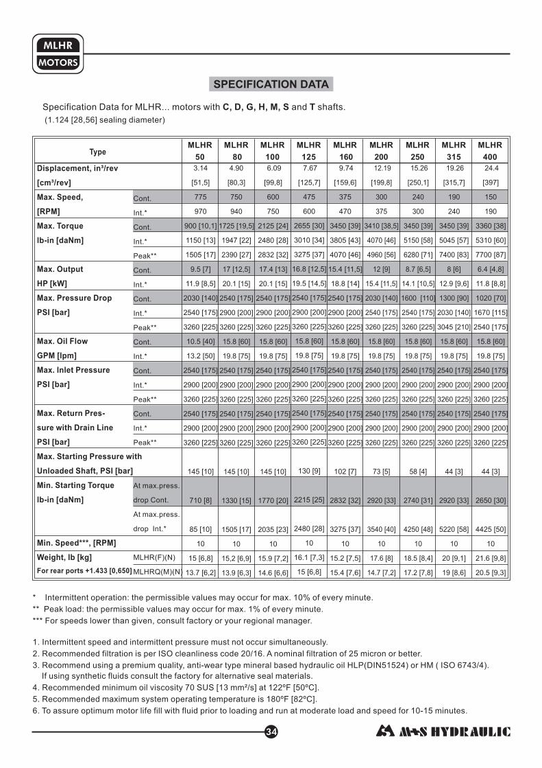
MOTORS
MLHR
34
SPECIFICATION DATA
* Intermittent operation: the permissible values may occur for max. 10% of every minute.
** Peak load: the permissible values may occur for max. 1% of every minute.
*** For speeds lower than given, consult factory or your regional manager.
1. Intermittent speed and intermittent pressure must not occur simultaneously.
2. Recommended filtration is per ISO cleanliness code 20/16. A nominal filtration of 25 micron or better.
3. Recommend using a premium quality, anti-wear type mineral based hydraulic oil HM ( ISO 6743/4).
If using synthetic fluids consult the factory for alternative seal materials.
4. Recommended minimum oil viscosity 70 SUS [13 mm²/s] at 122ºF [50ºC].
5. Recommended maximum system operating temperature is 180ºF [82ºC].
6. To assure optimum motor life fill with fluid prior to loading and run at moderate load and speed for 10-15 minutes.
HLP(DIN51524) or
Type
Displacement, in³/rev
[cm³/rev]
Max. Speed,
[RPM]
Max. Torque
[daNm]
Max. Output
HP [kW]
Max. Pressure Drop
PSI [bar]
Max. Oil Flow
GPM [lpm]
Max. Inlet Pressure
PSI [bar]
Max. Return Pres-
sure with Drain Line
PSI [bar]
Max. Starting Pressure with
Unloaded Shaft, PSI [bar]
Min. Starting Torque
- [daNm]
Min. Speed***, [RPM]
Weight, lb [kg]
lb-in
lb in
For rear ports +1.433 [0,650]
Cont.
Int.*
Cont.
Int.*
Peak**
Cont.
Int.*
Cont.
Int.*
Peak**
Cont.
Int.*
Cont.
Int.*
Peak**
Cont.
Int.*
Peak**
MLHR(F)(N)
MLHRQ(M)(N)
At max.press.
drop Cont.
At max.press.
drop Int.*
Specification Data for MLHR... motors with and shafts.C, D, G, H, M, S T
(1.124 [28,56] sealing diameter)
3.14
[51,5]
775
970
900 [10,1]
1150 [13]
1505 [17]
9.5 [7]
11.9 [8,5]
2030 [140]
2540 [175]
3260 [225]
10.5 [40]
13.2 [50]
2540 [175]
2900 [200]
3260 [225]
3260 [225]
145 [10]
710 [8]
85 [10]
10
15 [6,8]
13.7 [6,2]
2540 [175]
2900 [200]
MLHR
50
MLHR
80
4. 0
[80,3]
750
940
1725 [19,5]
1947 [22]
2390 [27]
17 [12,5]
20.1 [15]
2540 [175]
2900 [200]
3260 [225]
15.8 [60]
19.8 [75]
2540 [175]
2900 [200]
3260 [225]
2540 [175]
2900 [200]
3260 [225]
145 [10]
1330 [15]
1505 [17]
10
15,2 [6,9]
13.9 [6,3]
9 6.09
[99,8]
600
750
2125 [24]
2480 [28]
2832 [32]
17.4 [13]
20.1 [15]
2540 [175]
2900 [200]
3260 [225]
2540 [175]
2900 [200]
3260 [225]
2540 [175]
2900 [200]
3260 [225]
145 [10]
1770 [20]
2035 [23]
10
15.9 [7,2]
14.6 [6,6]
15.8 [60]
19.8 [75]
MLHR
100
7.67
[125,7]
475
600
2655 [30]
3010 [34]
3275 [37]
16.8 [12,5]
19.5 [14,5]
2540 [175]
2900 [200]
3260 [225]
2540 [175]
2900 [200]
3260 [225]
2540 [175]
2900 [200]
3260 [225]
130 [9]
2215 [25]
2480 [28]
10
16.1 [7,3]
15 [6,8]
15.8 [60]
19.8 [75]
MLHR
125
9.74
[159,6]
375
470
3450 [39]
3805 [43]
4070 [46]
15.4 [11,5]
18.8 [14]
2540 [175]
2900 [200]
3260 [225]
2540 [175]
2900 [200]
3260 [225]
2540 [175]
2900 [200]
3260 [225]
102 [7]
2832 [32]
3275 [37]
10
15.2 [7,5]
15.4 [7,6]
15.8 [60]
19.8 [75]
MLHR
160
12.19
[199,8]
300
375
3410 [38,5]
4070 [46]
4960 [56]
12 [9]
15.4 [11,5]
2030 [140]
2540 [175]
3260 [225]
2540 [175]
2900 [200]
3260 [225]
2540 [175]
2900 [200]
3260 [225]
73 [5]
2920 [33]
3540 [40]
10
17.6 [8]
14.7 [7,2]
15.8 [60]
19.8 [75]
MLHR
200
15.26
[250,1]
240
300
3450 [39]
5150 [58]
6280 [71]
8.7 [6,5]
14.1 [10,5]
1600 [110]
2540 [175]
3260 [225]
2540 [175]
2900 [200]
3260 [225]
2540 [175]
2900 [200]
3260 [225]
58 [4]
2740 [31]
4250 [48]
10
18.5 [8,4]
17.2 [7,8]
15.8 [60]
19.8 [75]
MLHR
250
MLHR
315
19.26
[315,7]
190
240
3450 [39]
5045 [57]
7400 [83]
8 [6]
12.9 [9,6]
1300 [90]
2030 [140]
3045 [210]
2540 [175]
2900 [200]
3260 [225]
44 [3]
2920 [33]
5220 [58]
10
20 [9,1]
19 [8,6]
15.8 [60]
19.8 [75]
2540 [175]
2900 [200]
3260 [225]
24.4
[397]
150
190
3360 [38]
5310 [60]
7700 [87]
6.4 [4,8]
11.8 [8,8]
1020 [70]
1670 [115]
2540 [175]
2540 [175]
2900 [200]
3260 [225]
2540 [175]
2900 [200]
3260 [225]
44 [3]
2650 [30]
4425 [50]
10
21.6 [9,8]
20.5 [9,3]
15.8 [60]
19.8 [75]
MLHR
400

35
SPECIFICATION DATA (continued)
MOTORS
MLHR
Type
Displacement, in³/rev
[cm³/rev]
Max. Speed,
[RPM]
Max. Torque
[daNm]
Max. Output
HP [kW]
Max. Pressure Drop
PSI [bar]
Max. Oil Flow
GPM [lpm]
Max. Inlet Pressure
PSI [bar]
Max. Return Pres-
sure with Drain Line
PSI [bar]
Max. Starting Pressure with
Unloaded Shaft, PSI [bar]
Min. Starting Torque
[daNm]
Min. Speed***, [RPM]
Weight, lb [kg]
lb-in
lb-in
For rear ports +1.433 [0,650]
Cont.
Int.*
Cont.
Int.*
Peak**
Cont.
Int.*
Cont.
Int.*
Peak**
Cont.
Int.*
Cont.
Int.*
Peak**
Cont.
Int.*
Peak**
At max.press.
drop Cont.
At max.press.
drop Int.*
MLHR
50
MLHR
80
MLHR
100
MLHR
125
MLHR
160
MLHR
200
MLHR
250
MLHR
315
MLHR
400
Specification Data for MLHR... motors with and shafts.B, K, R L
(1.378 [35] sealing diameter)
3.14
[51,5]
775
970
900 [10,1]
1150 [13]
1505 [17]
9.5 [7]
11.9 [8,5]
2030 [140]
2540 [175]
3260 [225]
2540 [175]
2900 [200]
3260 [225]
2540 [175]
2900 [200]
3260 [225]
145 [10]
710 [8]
885 [10]
10
15,2 [6,9]
10.5 [40]
13.2 [50]
4.90
[80,3]
750
940
1725 [19,5]
1947 [22]
2390 [27]
17 [12,5]
20.1 [15]
2540 [175]
2900 [200]
3260 [225]
2540 [175]
2900 [200]
3260 [225]
2540 [175]
2900 [200]
3260 [225]
145 [10]
1330 [15]
1505 [17]
10
15,4 [7]
15.8 [60]
19.8 [75]
6.09
[99,8]
600
750
2125 [24]
2480 [28]
2832 [32]
17.4 [13]
20.1 [15]
2540 [175]
2900 [200]
3260 [225]
2540 [175]
2900 [200]
3260 [225]
2540 [175]
2900 [200]
3260 [225]
145 [10]
1770 [20]
2035 [23]
10
16.1 [7,3]
15.8 [60]
19.8 [75]
7.67
[125,7]
475
600
2655 [30]
3010 [34]
3275 [37]
16.8 [12,5]
19.5 [14,5]
2540 [175]
2900 [200]
3260 [225]
2540 [175]
2900 [200]
3260 [225]
2540 [175]
2900 [200]
3260 [225]
130 [9]
2215 [25]
2480 [28]
10
16.3 [7,4]
15.8 [60]
19.8 [75]
9.74
[159,6]
375
470
3450 [39]
3805 [43]
4070 [46]
15.4 [11,5]
18.8 [14]
2540 [175]
2900 [200]
3260 [225]
2540 [175]
2900 [200]
3260 [225]
2540 [175]
2900 [200]
3260 [225]
102 [7]
2832 [32]
3275 [37]
10
15.4 [7,6]
15.8 [60]
19.8 [75]
12.19
[199,8]
300
375
4000 [45]
4425 [50]
4960 [56]
14.8 [11]
17.4 [13]
2540 [175]
2900 [200]
3260 [225]
2540 [175]
2900 [200]
3260 [225]
2540 [175]
2900 [200]
3260 [225]
73 [5]
3630 [41]
4070 [46]
10
18.9 [8,1]
15.8 [60]
19.8 [75]
15.26
[250,1]
240
300
4780 [54]
5400 [61]
6280 [71]
13.4 [10]
16.1 [12]
2540 [175]
2900 [200]
3260 [225]
2540 [175]
2900 [200]
3260 [225]
2540 [175]
2900 [200]
3260 [225]
58 [4]
4000 [45]
4870 [55]
10
18.7 [8,5]
15.8 [60]
19.8 [75]
19.26
[315,7]
190
240
4870 [55]
5580 [63]
7350 [83]
12 [9]
14.8 [11]
1960 [135]
2320 [160]
3045 [210]
2540 [175]
2900 [200]
3260 [225]
2540 [175]
2900 [200]
3260 [225]
44 [3]
4000 [45]
5840 [66]
10
20.3 [9,2]
15.8 [60]
19.8 [75]
24.4
[397]
150
190
5400 [61]
6100 [69]
7700 [87]
10.5 [7,8]
14.2 [10,6]
1670 [115]
2030 [140]
2540 [175]
2540 [175]
2900 [200]
3260 [225]
2540 [175]
2900 [200]
3260 [225]
44 [3]
4340 [49]
5400 [61]
10
21.8 [9,9]
15.8 [60]
19.8 [75]
* Intermittent operation: the permissible values may occur for max. 10% of every minute.
** Peak load: the permissible values may occur for max. 1% of every minute.
*** For speeds lower than given, consult factory or your regional manager.
1. Intermittent speed and intermittent pressure must not occur simultaneously.
2. Recommended filtration is per ISO cleanliness code 20/16. A nominal filtration of 25 micron or better.
3. Recommend using a premium quality, anti-wear type mineral based hydraulic oil HM ( ISO 6743/4).
If using synthetic fluids consult the factory for alternative seal materials.
4. Recommended minimum oil viscosity 70 SUS [13 mm²/s] at 122ºF [50ºC].
5. Recommended maximum system operating temperature is 180ºF [82ºC].
6. To assure optimum motor life fill with fluid prior to loading and run at moderate load and speed for 10-15 minutes.
HLP(DIN51524) or

36
MLHR
MOTORS
MLHR 50
MLHR 80
FUNCTION DIAGRAMS
0,5kW
1kW
2kW
6kW
4kW
8kW
MdaNm
0
2
4
6
8
10
12
14
16
18
20
0
Mlb-in
200
400
600
800
1600
1000
1200
1400
1800
222000
70 bar1020 PSI
50 bar730 PSI
n
cont.
int.
cont. int.
p=175 bar2540 PSI
140 bar2030 PSI
MdaNm
0
1
2
3
4
5
Mlb-in
6
7
8
9
10
11
12
0 RPM400200 600 800700 900100 300 500 1000
120 bar1740 PSI
30 bar430 PSI
100 bar1450 PSI
20 l/m
in5.3
GP
M
30 l/m
in7.9
GP
M
40 l/m
in10.6
GP
M
35 l/m
in9.2
GP
M
10 l/m
in2.6
GP
M
50 l/m
in13.2
GP
M
Q=
5 l/m
in1.3
GP
M
45 l/m
in11.9
GP
M
25 l/m
in6.6
GP
M
15 l/m
in4.0
GP
M
20 l/m
in5.3
GP
M
30 l/m
in7.9
GP
M
40 l/m
in10.6
GP
M
10 l/m
in2.6
GP
M
50 l/m
in13.2
GP
M
70 l/m
in18.5
GP
M
60 l/m
in15.9
GP
M
Q=
5 l/m
in1.3
GP
M
75 l/m
in19.8
GP
M
0
100
200
300
400
500
600
700
800
900
1000
1100
0 RPM400200 600 800700 900100 300 500
ncont. int.
p=200 bar2900 PSI
80 bar1160 PSI
60 bar870 PSI
30 bar430 PSI
100 bar1450 PSI
140 bar2030 PSI
120 bar1740 PSI
175 bar2540 PSI
The function diagrams data is for average performance of randomly selected motors at back pressure[ ] and oil with viscosity of [ ] at [ ].72.5÷145 PSI 5÷10 bar 150 SUS 32 mm²/s 122 F 50°C
o
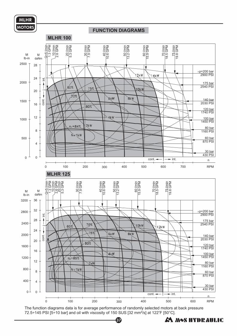
MLHR
MOTORS
37
MLHR 100
MLHR 125
0
800
1200
1600
2000
2400
400
2800
3200
MdaNm
0 RPM
n
cont.
int.
cont. int.
400200 600
20 l/m
in5.3
GP
M
30 l/m
in7.9
GP
M
40 l/m
in10.6
GP
M
10 l/m
in2.6
GP
M
50 l/m
in13.2
GP
M
70 l/m
in18.5
GP
M
60 l/m
in15.9
GP
M
Q=
5 l/m
in1.3
GP
M
75 l/m
in19.8
GP
M
100 300 500
0
4
8
12
16
20
0
Mlb-in
500
1000
1500
24
2000
282500
700
p=200 bar2900 PSI
80 bar1160 PSI
60 bar870 PSI
30 bar430 PSI
100 bar1450 PSI
140 bar2030 PSI
120 bar1740 PSI
175 bar2540 PSI
MdaNm
0 RPM
n
cont.
int.
cont. int.
400200 600
20 l/m
in5.3
GP
M
30 l/m
in7.9
GP
M
40 l/m
in10.6
GP
M
10 l/m
in2.6
GP
M
50 l/m
in13.2
GP
M
70 l/m
in18.5
GP
M
60 l/m
in15.9
GP
M
Q=
5 l/m
in1.3
GP
M
75 l/m
in19.8
GP
M
100 300 500
0
4
8
12
16
20
Mlb-in
24
32 p=200 bar2900 PSI
80 bar1160 PSI
60 bar870 PSI
30 bar430 PSI
100 bar1450 PSI
140 bar2030 PSI
120 bar1740 PSI
175 bar2540 PSI
28
36
The function diagrams data is for average performance of randomly selected motors at back pressure[ ] and oil with viscosity of [ ] at [ ].72.5÷145 PSI 5÷10 bar 150 SUS 32 mm²/s 122 F 50°C
o
FUNCTION DIAGRAMS

MLHR
MOTORS
38
MLHR 160
MLHR 200
MdaNm
RPM
n
cont.
int.
cont. int.
20 l/m
in5.3
GP
M
30 l/m
in7.9
GP
M
40 l/m
in10.6
GP
M
10 l/m
in2.6
GP
M
50 l/m
in13.2
GP
M
70 l/m
in18.5
GP
M
60 l/m
in15.9
GP
M
Q=
5 l/m
in1.3
GP
M
75 l/m
in19.8
GP
M
0
4
8
12
16
20
24
32
p=200 bar2900 PSI
80 bar1160 PSI
60 bar870 PSI
30 bar430 PSI
100 bar1450 PSI
140 bar2030 PSI
120 bar1740 PSI
175 bar2540 PSI
28
36
40
44
MdaNm
RPM
n
cont.
int.
cont. int.
20 l/m
in5.3
GP
M
30 l/m
in7.9
GP
M
40 l/m
in10.6
GP
M
10 l/m
in2.6
GP
M
50 l/m
in13.2
GP
M
70 l/m
in18.5
GP
M
60 l/m
in15.9
GP
M
Q=
5 l/m
in1.3
GP
M
75 l/m
in19.8
GP
M
Mlb-in
p=200 bar2900 PSI
80 bar1160 PSI
60 bar870 PSI
30 bar430 PSI
105 bar1520 PSI
140 bar2030 PSI
120 bar1740 PSI
175 bar2540 PSI
0
800
1200
1600
2000
2400
400
2800
3200
Mlb-in
3600
4000
0 400200100 300 450250150 35050
0
5
10
15
20
25
0
1000
1500
2000
302500
353000
40
45
500
3500
4000
4500 50
0 200100 300250150 35050
The function diagrams data is for average performance of randomly selected motors at back pressure[ ] and oil with viscosity of [ ] at [ ].72.5÷145 PSI 5÷10 bar 150 SUS 32 mm²/s 122 F 50°C
o
FUNCTION DIAGRAMS

MLHR
MOTORS
39
MLHR 250
MLHR 315
35
MdaNm
0
5
10
15
20
25
Mlb-in
30
40
45
50
55
60
65
0
1000
1500
2000
2500
3000
500
3500
4000
4500
5000
5500
6000
RPM0 200100 2251505025 75 125 175 250 300275
0
8
16
24
32
40
48
56
72
64
n
cont.
int.
cont. int.
20 l/m
in5.3
GP
M
30 l/m
in7.9
GP
M
40 l/m
in10.6
GP
M
10 l/m
in2.6
GP
M
50 l/m
in13.2
GP
M
70 l/m
in18.5
GP
M
60 l/m
in15.9
GP
M
Q=
5 l/m
in1.3
GP
M
75 l/m
in19.8
GP
M
p=200 bar2900 PSI
80 bar1160 PSI
60 bar870 PSI
30 bar430 PSI
105 bar1520 PSI
140 bar2030 PSI
175 bar2540 PSI
110 bar1600 PSI
ncont. int.
20 l/m
in5.3
GP
M
30 l/m
in7.9
GP
M
40 l/m
in10.6
GP
M
10 l/m
in2.6
GP
M
50 l/m
in13.2
GP
M
70 l/m
in18.5
GP
M
60 l/m
in15.9
GP
M
Q=
5 l/m
in1.3
GP
M
75 l/m
in19.8
GP
M
p=175 bar2540 PSI
135 bar1740 PSI
30 bar430 PSI
160 bar2320 PSI
80 bar1160 PSI
cont.
int.
0
1000
1500
2000
2500
3000
500
3500
4000
4500
5000
5500
6000
6500
0 200100 2251505025 75 125 175 RPM
MdaNm
Mlb-in
65 bar940 PSI
45 bar650 PSI
125 bar1810 PSI
The function diagrams data is for average performance of randomly selected motors at back pressure[ ] and oil with viscosity of [ ] at [ ].72.5÷145 PSI 5÷10 bar 150 SUS 32 mm²/s 122 F 50°C
o
FUNCTION DIAGRAMS

MLHR
MOTORS
40
MLHR 400
FUNCTION DIAGRAMS
20 l/m
in5.3
GP
M
30 l/m
in7.9
GP
M
40 l/m
in10.6
GP
M
10 l/m
in2.6
GP
M
50 l/m
in13.2
GP
M
70 l/m
in18.5
GP
M
60 l/m
in15.9
GP
M
Q=
5 l/m
in1.3
GP
M
75 l/m
in19.8
GP
M
MdaNm
0
4
8
12
16
20
24
32
28
36
40
44
0
800
1200
1600
2000
2400
400
2800
3200
Mlb-in
3600
4000
48
52
56
60
64
4400
4800
5200
5600
RPM
ncont. int.
100 20 30 5040 60 70 9080 100 110 120 130 140 150 160 170 180 190
15 l/m
in4.0
GP
M
p=125 bar1810 PSI
65 bar940 PSI
40 bar580 PSI
30 bar430 PSI
80 bar1160 PSI
90 bar1300 PSI
110 bar1600 PSI
55 bar800 PSI
The function diagrams data is for average performance of randomly selected motors at back pressure[ ] and oil with viscosity of [ ] at [ ].72.5÷145 PSI 5÷10 bar 150 SUS 32 mm²/s 122 F 50°C
o

MLHR(F) 50
MLHR(F) 80
MLHR(F) 100
MLHR(F) 125
MLHR(F) 160
MLHR(F) 200
MLHR(F) 250
MLHR(F) 315
MLHR(F) 400
MLHRQ(M) 50
MLHRQ(M) 80
MLHRQ(M) 100
MLHRQ(M) 125
MLHRQ(M) 160
MLHRQ(M) 200
MLHRQ(M) 250
MLHRQ(M) 315
MLHRQ(M) 400
5.51 [140,0]
5.71 [145,0]
5.85 [148,5]
6.00 [152,5]
6.24 [158,5]
6.52 [165,5]
6.87 [174,5]
7.30 [185,5]
7.89 [200,5]
5.67 [144,0]
5.87 [149,0]
6.00 [152,5]
6.18 [157,0]
6.42 [163,0]
6.69 [170,0]
7.03 [178,5]
7.48 [190,0]
8.05 [204,5]
MOTORS
MLHR
41
.35 [9,0]
.55 [14,0]
.69 [17,4]
.86 [21,8]
1.09 [27,8]
1.37 [34,8]
1.71 [43,5]
2.16 [54,8]
2.73 [69,4]
DIMENSIONS AND MOUNTING DATA
Standard Rotation
Viewed from Shaft EndPort Pressurized -Port Pressurized -
A CW
B CCW
Reverse Rotation
Viewed from Shaft EndPort Pressurized -Port Pressurized -
A CCW
B CW
Shaft Dim.See Page 28
Flange Dim.See Page 42
Port Dim.See Page 42
max Dia.
4 134. [105]
T
P(A,B)
C
P(A,B)
Port B
Port A
Port B
Port A
3 , 9
4xM8
2xM22x1,5
M14x1,5
4 , 7
4x -18 UNC
2x -14 UNF
-20 UNF
78/
716/
516/ 5
16/
5 , 8
4x -18 UNC
2x½-14 NPTF
-20 UNF716/
2 , 6
4xM8
2xG½
G¼
C
P
T
(A,B)
Versions
in [mm]
Rear ports
Version 6 8 97
max L
[40,15/39,85]
[76,3/75,7] [80,3/79,7]
1.580/1.569
3.004/2.9803.161/3.138
S ShaftT Shaft
G ShaftC,H ShaftM Shaft
2.45[62,2]max
MLHR, MLHRF
D Shaft
1.984[50,4]max
1.661[42,2]max
1.84[46,75]
max
MLHRQ, MLHRM
1.84[46,75]
max
S ShaftM Shaft
2.45[62,2]max
D Shaft
1.984[50,4]max
1.661[42,2]max
T ShaftG ShaftC,H Shaft
L1
max Dia.
4 134. [105]
C
L1
max L
[44,15/43,85]
1.738/1.726
* - For Rear Ported Motors.
Versions 2,3,4,5
L , in [mm]max
*Versions 6,7,8,9Type Type L in [mm]1,
Versions 2,3,4,5
L , in [mm]max
*Versions 6,7,8,9
max L
6.30 [160,0]
6.50 [165,0]
6.63 [168,5]
6.81 [173,0]
7.05 [179,0]
7.32 [186,0]
7.60 [194,5]
8.11 [206,0]
8.68 [220,5]
6.14 [156,0]
6.34 [161,0]
6.48 [164,5]
6.63 [168,5]
6.87 [174,5]
7.15 [181,5]
7.50 [190,5]
7.93 [201,5]
8.52 [216,5]
R Shaft K Shaft L Shaft
2.24[56,8]max
2.57[65,28]
max
B Shaft
2.615[66,4]max
Shaft Dim.See Page 29

[55,1/54,9]
2.169/2.161
4.197/4.181 Dia.[106,6/106,2]
2x.541/.525[13,75/13,35]
Dia. Thru
5.157[131]max
4,232 7,5[10 ] max
3.250/3.246[82,55/82,45]
Pilot Dia.
.709[18]
.25 [6,4] max2
MOTORS
MLHR
42
MOUNTING
PORTS
M Qand - Square Flange
.59 [15]min deep
[2,6/2,2]
.110/.087
1.749/1.746[44,45/44,35]
3.228 [82]
4xM10*4x3/8-16 UNC**
[18,1/17,9]
.713/.705
[20]
.787
[25]
.984
max L
[ ]5
.197
Rear PortsSide Ports
Version 2 3 4 5 Version 6 7 8 9
in [mm]
3 , 9
4xM8
2xM22x1,5
M14x1,5
4 , 7
4x -18 UNC
2x -14 UNF
-20 UNF
78/
716/
516/ 5
16/
5 , 8
4x -18 UNC
2x½-14 NPTF
-20 UNF716/
2 , 6
4xM8
2xG½
G¼
C
P
T
(A,B)
Versions
Standard Rotation
Viewed from Shaft EndPort Pressurized -Port Pressurized -
A CW
B CCW
Reverse Rotation
Viewed from Shaft EndPort Pressurized -Port Pressurized -
A CCW
B CW
[55,1/54,9]
2.169/2.1613.254/3.246 Dia.
[82,65/82,45]
[82]3.228
[20,3/19,7]
.792/.768
[20,3/19,7]
.792/.768
[18,1/17,9]
.713/.705
Port B
P(A,B)
C
TT
P(A,B)
Port A
Port B
Port A
[ ]7,1
.279
[ ,2]311.23
4,232 7,5[10 ] max
[55,1/54,9]
2.169/2.161
[55,1/54,9]
2.169/2.161
4,232 7,5[10 ] max
[20,3/19,7]
.792/.768
[20,3/19,7]
.792/.768
SAE A Flange
F - Magneto Flange
6x.541/.525[13,75/13,35]
Dia. Thru
4.197/4.181[106,6/106,2]
Dia.
450
[55,1/54,9]
2.169/2.161
5.157[131]max
4,232 7,5[10 ] max
3.250/3.246[82,55/82,45]
Pilot Dia.
.25 [6,4] max2
.709[18]
*
**
For M
Q
Flange
For Flange

MOTORS
MLHR
43
2
3
4
5
6
7
8
9
M L H R
ORDER CODE
Pos.1 Pos.4
Pos.2
1 2 3 4 5 6 7 8
omit
N
Pos.3
omit
F
Q
M
50
80
100
125
160
200
250
315
400
cm /rev]
cm /rev]
cm /rev]
cm /rev]
cm /rev]
cm /rev]
cm /rev]
cm /rev]
cm /rev]
3
3
3
3
3
3
3
3
3
9
The hydraulic motors are mangano-phosphatized as standard.
Pos.5
Notes:
C
VC
D
G
H
M
VM
S
T
B
K
L
R
Pos.9
omit
omit
1
Pos.7
Pos.6
Pos.8
omit
U
- Displacement code
- Mounting Flange
- SAE A
- Magneto
- S
, two holes
, six holes
- Square metric, four bolts M10
quare, four bolts
- 3.14 [ 51,5 cm /rev]
- 4.90 [ 80,3 cm /rev]
- 6.09 [ 99,8 cm /rev]
- 7.67 [125,7 cm /rev]
- 9.74 [159,6 cm /rev]
- 12.19 [199,8 cm /rev]
- 15.26 [250,1 cm /rev]
- 19.26 [315,7 cm /rev]
- 24.40 [397,0 cm /rev]
3
3
3
3
3
3
3
3
3
in /rev
in /rev
in /rev
in /rev
in /rev
in /rev
in /rev
in /rev
in /rev
3
3
3
3
3
3
3
3
3
- [see pages 28 and 29]Shaft Extensions*
- 1" [25,4] straight, Parallel key
- 1" [25,4] straight, Parallel key w/ corrosion
resistant bushing
- / " [22,2] straight, Parallel key
- 1" [25,4] SAE 6B Splined
- 1" [25,4] straight w/ .406 [10,3] Crosshole
- 25 mm straight, Parallel key
- 25 mm straight, Parallel key w/ corrosion
resistant bushing
- / " [22,2] 13T Splined
- 1" [25,4] SAE J501 Tapered
- 32 mm straight, Parallel key
- 1¼" [31,75] straight, Parallel key
- 1¼" [31,75] 14T Splined
- 1¼" [31,75] SAE J501 Tapered
7
7
8
8
- [needle bearings]Option
- none
- with needle bearings
- [standard manifold to each]Port Size/Type
- side ports, 2xG1/2, G1/4, BSP thread, ISO 228
- side ports, 2xM22x1,5, M14x1,5, metric thread,
ISO 262
- side ports, 2x7/8-14 UNF, O-ring, 7/16-20 UNF
- side ports, 2x1/2-14 NPTF, 7/16-20 UNF
- rear ports, 2xG1/2, G1/4, BSP thread, ISO 228
- rear ports, 2x7/8-14 UNF, O-ring, 7/16-20 UNF
- rear ports, 2x1/2-14 NPTF, 7/16-20 UNF
- rear ports, 2xM22x1,5, M14x1,5, metric thread,
ISO 262
- Shaft Seal Version [see page 31]
-
- High pressure shaft seal (without check valves)
Standard shaft seal
- Drain Port
- Design Series
- with drain port
- without drain port
- Special Features [see page 103]
- Factory specified
The following combinations are not allowed:
* The permissible output torque for shafts must not be exceeded!
- and flange with , , , shafts;
- option with , , , shafts, option or option;
- , , , shafts with option.
Q M B K L R
N B K L R U RS
B K L R U

44
HYDRAULIC MOTORS MLHPL
APPLICATION
� Conveyors
� Feeding mechanism of robots and manipulators
� Metal working machines
� Textile machines
� Agricultur machinesal
� Food industries
Specification data ................. 45
Dimensions and mounting .... 46
Shaft extensions ................... 47
Permissible shaft loads ......... 48
Order code ............................ 48
CONTENTS OPTIONS
� Model - Spool valve, gerotor
� Antifriction bearingneedle
� Flange mount
� Shafts - straight, splined and tapered
� Metric and BSPP ports
� Other special features
Pressure Losses
1450 [ 0 ]1 0
2030 [140]
Pressure drop
[ ]PSI bar
Viscosity
SUS [ ]mm /s2
Oil flow indrain line
[ ]GPM lpm
98 [20]
164 [35]
98 20[ ]
[ ]164 35
.660 [2,5]
.476 [1,8]
.925 [3,5]
.740 [2,8]
Oil flow in drain line
7020 60504030100 Q, lpm
0 2 84 106 12 Q, GPM
80
0
14 16 18 20
100
200
400
300
0
5
10
15
20
25
pbar
pPSI
30
GENERAL
24.16 396[ ]
1515
cont.: [ ] int.: [ ]4415 50 5222 59
[ ]23.5 17,5
[ ] int.: [ ]cont.: 2030 140 2540 175
[ ]20 75
10
Mineral based- HLP(DIN 51524) or HM(ISO 6743/4)
-40÷284 [-40÷140]
[ ]98÷347 20÷75
ISO code 20/16 (Min. recommended fluid filtration of 25 micron )s
Max. Displacement, in /rev [cm /rev]3 3
Max. Speed, [RPM]
Max. Torque, lb-in [daNm]
Max. Output, HP [kW]
Max. Pressure Drop, PSI [bar]
Max. Oil Flow, GPM [lpm]
Min. Speed, [RPM]
Pressure fluid
Temperature range, F [ C]O O
Optimal Viscosity range, SUS [mm /s]2
Filtration

SPECIFICATION DATA
45
MLHPL
Type
Displacement, in /rev [cm /rev]
Max. Speed,
[RPM]
Max. Torque
[daNm]
Max. Output
HP [kW]
Max. Pressure Drop
PSI [bar]
Max. Oil Flow
GPM [lpm]
Max. Inlet Pressure
PSI [bar]
Max. Return Pressure
without Drain
Line or Max. Pressure
in Drain Line,
PSI [bar]
Max. Return Pressure
with Drain Line
PSI [bar]
Max. Starting Pressure with
Unloaded Shaft, PSI [bar]
Min. Starting Torque - [daNm]
Min. Speed***, [RPM]
Weight, lb [kg]
3 3
lb-in
lb in
80
MLHPLPL
50
MLH
100
MLHPL
125
MLHPL
160
MLHPL
200
MLHPL MLHPL
250
MLHPL
315
MLHPL
400
Cont.
Int.*
Cont.
Int.*
Peak**
Cont.
Int.*
Cont.
Int.*
Peak**
Cont.
Int.*
Cont.
Int.*
Peak**
Cont. 0-100 RPM
Cont. 100-300 RPM
Cont. 300-600 RPM
Cont. >600 RPM
Int.* 0-max. RPM
Cont.
Int.*
Peak**
3.02 49,5
832 9,4
1054 11,9
1240 14,0
13.3 9,9
16.8 12,5
2030 140
2540 175
3260 225
16 60
20 75
2540 175
2900 200
3260 225
1450 100
725
365 25
220 15
1450 100
2540 175
2900 200
3260 225
145 10
681 7,7
18.5 8,4
[ ]
1210
1515
[ ]
[ ]
[ ]
[ ]
[ ]
[ ]
[ ]
[ ]
[ ]
[ ]
[ ]
[ ]
[ ]
[ ]
[ ]
[ ]
[ ]
[ ]
[ ]
[ ]
[ ]
10
[ ]
[ ]
[ ]
50
4.83 79,2
1336 15,1
1725 19,5
1947 22,0
13.3 [9,9]
16.8 [12,5]
2030 [140]
2540 [175]
3260 [225]
16 [60]
20 [75]
2540 [175]
2900 [200]
3260 [225]
1450 [100]
725 [ ]
365 [25]
220 [15]
1450 [100]
2540 [175]
2900 [200]
3260 [225]
145 [10]
1150
18.7 8,5
[ ]
755
945
[ ]
[ ]
[ ]
[13]
10
[ ]
50
6.04 99
1708 19,3
2097 23,7
2390 27,0
13.3 [9,9]
16.8 [12,5]
2030 [140]
2540 [175]
3260 [225]
16 [60]
20 [75]
2540 [175]
2900 [200]
3260 [225]
1450 [100]
725 [ ]
365 [25]
220 [15]
1450 [100]
2540 [175]
2900 [200]
3260 [225]
145 [10]
1487 16,8
19.4 8,8
[ ]
605
755
[ ]
[ ]
[ ]
[ ]
10
[ ]
50
7.55 123,8
2100 23,7
2637 29,8
3230 36,5
13.3 [9,9]
16.8 [12,5]
2030 [140]
2540 [175]
3260 [225]
16 [60]
20 [75]
2540 [175]
2900 [200]
3260 [225]
1450 [100]
725 [ ]
365 [25]
220 [15]
1450 [100]
2540 [175]
2900 [200]
3260 [225]
19.6 8,9
[ ]
485
605
[ ]
[ ]
[ ]
131 [9]
21,0 [1860]
10
[ ]
50
9.66 158,4
2770 31,3
3345 37,8
3717 42
15.7 11,7
16.8 [12,5]
2030 [140]
2540 [175]
3260 [225]
16 [60]
20 [75]
2540 [175]
2900 [200]
3260 [225]
1450 [100]
725 [ ]
365 [25]
220 [15]
1450 [100]
2540 [175]
2900 [200]
3260 [225]
20 9,1
[ ]
378
472
[ ]
[ ]
[ ]
[ ]
116 [8]
28,0 [2478]
10
[ ]
50
12.1 198
3240 36,6
4035 45,6
4700 53
13.8 10,3
20.8 15,5
2030 [140]
2540 [175]
3260 [225]
16 [60]
20 [75]
2540 [175]
2900 [200]
3260 [225]
1450 [100]
725 [ ]
365 [25]
220 [15]
1450 [100]
2540 [175]
2900 [200]
3260 [225]
2850 32,2
20.9 9,5
[ ]
303
378
[ ]
[ ]
[ ]
[ ]
[ ]
[ ]
[ ]
10
[ ]
100 7
50
15.1 247,5
4160
5160 58,3
5930
13.1 9,8
23.5 17,5
2030 [140]
2540 [175]
3260 [225]
16 [60]
20 [75]
2540 [175]
2900 [200]
3260 [225]
1450 [100]
725 [ ]
365 [25]
220 [15]
1450 [100]
2540 [175]
2900 [200]
3260 [225]
3665 41,4
22 10,0
47
67
[ ]
242
303
[ ]
[ ]
[ ]
[ ]
[ ]
87 [6]
[ ]
10
[ ]
50
19.3 316,8
4300 48,6
4956
7523
10.2 7,6
1300
2030 [140]
3260 [225]
16 [60]
20 [75]
2540 [175]
2900 [200]
3260 [225]
1450 [100]
725 [ ]
365 [25]
220 [15]
1450 [100]
2540 [175]
2900 [200]
3260 [225]
3805 43,0
23.6 10,7
[ ]
190
236
[ ]
[56]
[85]
[ ]
11 [8,2]
[120]
73 [5]
[ ]
10
[ ]
50
24.16 396
4425
5222
7560 85,4
8.9 6,6
12.3 9,2
1015
1665
2610
16 [60]
20 [75]
2540 [175]
2900 [200]
3260 [225]
1450 [100]
725 [ ]
365 [25]
220 [15]
1450 [100]
2540 [175]
2900 [200]
3260 [225]
73 [5]
3900 44,0
25.1 11,4
[ ]
150
189
[50]
[59]
[ ]
[ ]
[ ]
[95]
[115]
[180]
[ ]
10
[ ]
50
* Intermittent operation: the permissible values may occur for max. 10% of every minute.
** Peak load: the permissible values may occur for max. 1% of every minute.
*** For speeds lower than given, consult factory or your regional manager.
1. Intermittent speed and intermittent pressure drop must not occur simultaneously.
2. Recommended filtration is per ISO cleanliness code 20/16. A nominal filtration of 25 micron or better.
3. Recommend using a premium quality, anti-wear type mineral based hydraulic oil HM (ISO 6743/4).
If using synthetic fluids consult the factory for alternative seal materials.
4. Recommended minimum oil viscosity 70 SUS [13 mm²/s] at 122ºF [50ºC].
5. Recommended maximum system operating temperature is 180ºF [82ºC].
6. To assure optimum motor life fill with fluid prior to loading and run at moderate load and speed for 10-15 minutes.
HLP(DIN51524) or

2
2xG½
G¼
P
T
(A,B)
Versions
4
2x -14 UNF
-20 UNF
78/
716/
5
2x½-14 NPTF
-20 UNF716/
DIMENSIONS AND MOUNTING DATA
46
K ShaftL Shaft
G Shaft
2.32[59]
2.71769[ ]
2.402[61]
2.126[54]
2.65767,5[ ]
R Shaft B Shaft
C Shaft
Shaft Dim.See Page 47
Standard Rotation
A CWB CCW
Viewed from Shaft EndPort Pressurized -Port Pressurized -
Reverse Rotation
A CCWB CW
Viewed from Shaft EndPort Pressurized -Port Pressurized -
MLHPL
Square Mount (4 Holes)
MOUNTING
in [mm]
4x.531 Dia.[ ]13,5
2.165[55]
4.197/4.181 Dia.[106,6/106,2]
max[96]
3.779
Version 2 5 Version 4
Port A
Port B
Port A
Port B
Side Ports
F Oval Mount (4 Holes)
Type
50
80
100
125
160
200
250
315
400
MLHPL
MLHPL
MLHPL
MLHPL
MLHPL
MLHPL
MLHPL
MLHPL
MLHPL
L ,
[ ]
[ ]
[ ]
[ ]
[ ]
max mm [in]
[ ]
[ ]
[ ]
[ ]
5.71 145,0
5.87 149,0
5.96 151,5
6.10 155,0
6.28 159,5
6.49 165,0
6.75 171,5
7.13 181,0
7.54 191,5
L ,
[ ]
[ ]
[ ]
[ ]
[ ]
[ ]
1 in [mm]
[ ]
[ ]
[ ]
.26 6,67
.42 10,67
.52 13,33
.66 16,67
.84 21,33
1.05 26,67
1.31 33,33
1.68 42,67
2.10 53,33
max L
Port A Port B
P(A,B)
.793/.781[20,15/19,58]
L1
T3.386 [86] Dia.
3.58 [91] Dia. max
3.21[81,5]
.321/.309[8,15/7,85]
.793/.781[20,15/19,58]
5.16[131]max
45o
3.25/3.24682,55/82,45[ ]
Pilot Dia.
.669[17]
3.20981,5[ ]
.327/.303,3/7,7[8 ]
3.25/3.24682,55/82,45[ ]
Pilot Dia.
.669[17]
3.20981,5[ ]
.327/.303,3/7,7[8 ]
5.119 [130]
4.198/4.182Dia.106,6/106,2[ ]
4.016
[102]
2.165[55]
4x.531 Dia.[ ]13,5

47
SHAFT EXTENSIONS FOR MLHPL AND MLHRL
MLHPL+MLHRL
MOTORSMOTORS
L
14T Splined, 1¼'' [31,75], ANS B92.1-1976Max. Torque 6815 [77 daNm]lb-in
/5 16/5 16
1¼" [31,75],SAE J501 Tapered
Parallel key "x "x1"
Max. Torque 6815 - [77 daNm]lb in
R
/5 16/5 161¼" [31,75] , Parallel key "x "x1¼" BS 46
Max. Torque 6815 [77 daNm]
straight
lb-in
K
1.378 Dia.
[35]
DP 12/24
Teeth 14
Pressure angle 30°
1.248/1.246 Dia.
[31,7/31,65]
1.516/1.476
[38,5/37,5]
2.205 [56]
3/8-16 UNC
.63[16] min Deep
C
1'' [25,4] straight, Parallel key ¼''x ¼''x 1 '' BS46Max. Torque 3010 [34 daNm]
¼lb-in
G
- Motor Mounting Surfase
Requirement max. Torque must be not exceeded.
1/4-20 UNC
.63[16] min Deep
.313/.312
[6,4/6,35]
1.11/1.101
[28,2/27,97]
1.693 [43]1/.999 Dia.
[25,4/25,38]
.051 [1,3]
.217 [5,5]
1.378 Dia.
[35]
.941/.937
[23,9/23,8]
1/4-20 UNC
.63[16] min Deep
.246/.245
[6,25/6,225]
.847/.845 Dia.
[21,52/21,475]
.992/.99 Dia.
[25,2/25,15]
1'' [25,4],Max. Torque
Splined BS 2059 (SAE 6B)3010 [34 daNm]lb-in
1.889/1.858
[48/47,2]
1.25/1.248 Dia.
[31,75/31,70]
.313/.312
[7,96/7,94]
1.381/1.371
[35,08/34,83]
3/8-16 UNC
.63[16] min Deep
1.378 Dia.
[35]
Tightening torque for Nut
1680÷1860 - [20±1 daNm]lb in
1.5 Taper per Foot
[cone 1:8]
2.283 [58]
.156
[4]
Dia.
1 / " [36,5] across flat716
2.177/2.154
[55,3/54,7]
1.251 Dia.
[31,775]
.236
[6]
1.378 Dia.
[35]
1-20UNEF
Nut 1-20UNEF
.313/.312
[7,96/7,94]
.156/.152
[3,96/3,86]
1.378 [35]
1.969 [50]
1.261/1.26 Dia.
[32,018/32,002]
M8
.866 [22] min. Deep
1.378/1.37
[35/34,8]
.394/.392
[10/9,964]
1.378 Dia.
[35]
in [mm]
B
ø32 , Parallel key A10x8x40 DIN 6885Max. Torque 6815 [77 daNm]lb-in
.941/.937
[23,9/23,8]
1.693 [43]
.276
[7]
1.016/1.012
[25,8/25,7]
.051 [1,3]
1.378 Dia.
[35]
A
A
A-A

48
MLHPL
omit
F
2
4
5
M L H P L
ORDER CODE
Pos.1
Pos.6
Pos.2
1 2 3 4 5 6
omit
50
80
100
125
160
200
250
315
400
- 3.02 in /rev
- 4.83 in /rev
- 6.04 in /rev
- 7.55 in /rev
- 9.66 in /rev
- 12.1 in /rev
- 15.1 in /rev
- 19.3 in /rev
- 24.16 in /rev
0
0
0
3
3
3
3
3
3
3
3
3
The hydraulic motors are mangano-phosphatized as standard.
Pos.4
Pos.3
B
K
L
R
C
G
Pos.5
PERMISSIBLE SHAFT LOADS FOR MLHPL AND MLHRL
- Mounting Flange
- Square mount, four holes
-Oval mount, four holes
- 3.02 in /rev [ 49,5 cm /rev]
- 4.83 in /rev [ 79,2 cm /rev]
- 6.04 in /rev [ 99,0 cm /rev]
- 7.55 in /rev [123,8 cm /rev]
- 9.66 in /rev [158,4 cm /rev]
- 12.1 in /rev [198,0 cm /rev]
- 15.1 in /rev [247,5 cm /rev]
- 19.3 in /rev [316,8 cm /rev]
- 24.16 in /rev [396,0 cm /rev]
0
0
0
3 3
3 3
3 3
3 3
3 3
3 3
3 3
3 3
3 3
- Displacement code*
- Shaft Extensions**
-
-
-
ø32 straight, Parallel key
1¼”[31,75] straight, Parallel key
- 1¼”[31,75] splined 14T ANS B 92.1-1976
1¼”[31,75] tapered SAE J 501
- ø25,4 straight, Parallel key
- ø25,4 splined BS 2059 (SAE 6B)
- Port Size/Type [standard manifold to each]
- side ports, 2xG1/2, G1/4, BSP thread, ISO 228
- side ports, 2x7/8-14 UNF, O-ring, 7/16-20 UNF
- side ports, 2x1/2-14 NPTF, 7/16-20 UNF
- Special Features [see page 103]
- Design Series
- Factory specified
NOTES:
*
**
For the Function Diagrams please look at "M+S Hydraulic" Catalogue for MLHP motors, pages 19÷23.
The permissible output torque for shafts must not be exceeded!
The curves apply to a B10 bearings life of 2000 hrs
ABC
- Max. radial shaft load.- n=50 min-
-1
n=100 min- n=200 min- n=400 min
-1
-1
-1
DE
PrdaN
0
1000
2000
3000
4000
5000
6000
Prlbs.
7000
4 3 2 1 0 -1 -1.57 in.
P =300 daN [674 lbs]max
mm

Specification data ................ 50
Dimensions and mounting ... 51
Shaft versions ........................ 47
Permissible shaft loads ......... 45
Order code ............................. 52
CONTENTS OPTIONS
� Model - Spool valve, roll-gerotor
� Antifriction bearingsneedle
� Flange mount
� Shafts - straight, splined and tapered
� SAE and BSPP ports
� Other special features
GENERAL
49
HYDRAULIC MOTORS MLHRL
Pressure Losses
1450 [100]
2030 [140]
Pressure drop
PSI [bar]
Viscosity
SUS [mm /s]2
Oil flow indrain line
GPM [lpm]
98 [20]
164 [35]
98 [20]
164 [35]
.660 [2,5]
.476 [1,8]
.925 [3,5]
.740 [2,8]
Oil flow in drain line
7020 60504030100 Q, lpm
0 2 84 106 12 Q, GPM
80
0
14 16 18 20
100
200
400
300
0
5
10
15
20
25
pbar
pPSI
30
APPLICATION
� Conveyors
� Feeding mechanism of robots and manipulators
� Metal working machines
� Textile machines
� Agricultur machinesal
� Food industries
Max. Displacement, in /rev [cm /rev]3 3
Max. Speed, [RPM]
Max. Torque, lb-in [daNm]
Max. Output, HP [kW]
Max. Pressure Drop, PSI [bar]
Max. Oil Flow, GPM [lpm]
Min. Speed, [RPM]
Pressure fluid
Temperature range, F [ C]O O
Optimal Viscosity range, SUS [mm /s]2
Filtration
24.4 397[ ]
970
cont.: [ ] int.: [ ]5400 61 6100 69
[ ]21.5 16
[ ] int.: [ ]cont.: 2540 175 2900 200
[ ]20 75
10
Mineral based- HLP(DIN 51524) or HM(ISO 6743/4)
-40÷284 [-40÷140]
[ ]98÷347 20÷75
ISO code 20/16 (Min. recommended fluid filtration of 25 micron )s

MLHRL
MOTORSMOTORS
SPECIFICATION DATA
MLHRL
80
MLHRL
50
MLHRL
100
MLHRL
125
MLHRL
160
MLHRL
200
MLHRL
250
MLHRL
315
MLHRL
400Type
Displacement, in³/rev [cm³/rev]
Max. Speed,
[RPM]
Max. Torque
[daNm]
Max. Output
HP [kW]
Max. Pressure Drop
PSI [bar]
Max. Oil Flow
GPM [lpm]
Max. Inlet Pressure
PSI [bar]
Max. Return Pres-
sure without Drain
Line or Max. Pres-
sure in Drain Line,
PSI [bar]
Max. Return Pres-
sure with Drain Line
PSI [bar]
Max. Starting Pressure with
Unloaded Shaft, PSI [bar]
Min. Starting Torque - [daNm]
Min. Speed***, [RPM]
Weight, lb [kg]
lb-in
lb in
Cont.
Int.*
Cont.
Int.*
Peak**
Cont.
Int.*
Cont.
Int.*
Peak**
Cont.
Int.*
Cont.
Int.*
Peak**
Cont. 0-100 RPM
Cont. 100-300 RPM
Cont. 300-600 RPM
Cont. >600 RPM
Int.* 0-max. RPM
Cont.
Int.*
Peak**
3.14 [51,5]
775
970
900 [10,1]
1150 [13]
1505 [17]
9.5 [7]
11.9 [8,5]
2030 [140]
2540 [175]
3260 [225]
11 [40]
13 [50]
2540 [175]
2900 [200]
3260 [225]
1450 [100]
725 [50]
365 [25]
220 [15]
1450 [100]
2030 [140]
175]
3260 [225]
145 [
710 [8]
10
18.7 [8,5]
2540 [
10]
4.90[80,3]
750
940
1770[20]
1947[22,0]
2390[27,0]
17[12,5]
20.1[15]
2540 [175]
2900 [200]
3260 [225]
16 [60]
20 [75]
2900 [200]
145 [
10
19 [8,6]
2540 [175]
2900 [200]
3260 [225]
1450 [100]
725 [50]
365 [25]
220 [15]
1450 [100]
2540 [175]
3260 [225
10]
1330[15]
6.09[99,8]
600
750
2125[24]
2480[28]
2832 [32]
17.4[13]
20.1[15]
145 [
10
19.6 [8,9]
2540 [175]
2900 [200]
3260 [225]
16 [60]
20 [75]
2540 [175]
2900 [200]
3260 [225]
1450 [100]
725 [50]
365 [25]
220 [15]
1450 [100]
2540 [175]
2900 [200]
3260 [225
10]
1770[20]
7.67[125,7]
475
600
2655[30]
3010[34]
3275[37]
16.8[12,5]
21.5[16]
130 [
2215[25]
10
19.8 [9,0]
2540 [175]
2900 [200]
3260 [225]
16 [60]
20 [75]
2540 [175]
2900 [200]
3260 [225]
1450 [100]
725 [50]
365 [25]
220 [15]
1450 [100]
2540 [175]
2900 [200]
3260 [225
9]
9.74 [159,6]
375
470
3450[39]
3805 [43]
4070[46]
15.4[11,5]
18.8[14]
102 [
2835[32]
10
20.3 [9,2]
2540 [175]
2900 [200]
3260 [225]
16 [60]
20 [75]
2540 [175]
2900 [200]
3260 [225]
1450 [100]
725 [50]
365 [25]
220 [15]
1450 [100]
2540 [175]
2900 [200]
3260 [225
7]
12.19[199,8]
300
375
4000[45]
4425[50]
4960 [56]
14.8[11]
17.4[13]
73 [
3275[37]
10
21.2 [9,6]
2540 [175]
2900 [200]
3260 [225]
16 [60]
20 [75]
2540 [175]
2900 [200]
3260 [225]
1450 [100]
725 [50]
365 [25]
220 [15]
1450 [100]
2540 [175]
2900 [200]
3260 [225
5]
15.26[250,1]
240
300
4780[54]
5400[61]
6280[71]
13.4[10]
16.1[12]
58 [
4000[45]
10
22.3 [10,1]
2540 [175]
2900 [200]
3260 [225]
16 [60]
20 [75]
2540 [175]
2900 [200]
3260 [225]
1450 [100]
725 [50]
365 [25]
220 [15]
1450 [100]
2540 [175]
2900 [200]
3260 [225
4]
19.26[315,7]
190
240
4870[55]
5580[63]
7350[83]
12[9]
14.8[11]
1960[135]
2320[160]
3045[210]
44 [
10
23.8 [10,8]
16 [60]
20 [75]
2540 [175]
2900 [200]
3260 [225]
1450 [100]
725 [50]
365 [25]
220 [15]
1450 [100]
2540 [175]
2900 [200]
3260 [225
3]
4000[45]
24.4[397]
150
190
5400[61]
6100[69]
7700[87]
10.5[7,8]
14.2[10,6]
1670[115]
2030 [140]
2540[175]
44 [
4340[49]
10
25.4 [11,5]
16 [60]
20 [75]
2540 [175]
2900 [200]
3260 [225]
1450 [100]
725 [50]
365 [25]
220 [15]
1450 [100]
2540 [175]
2900 [200]
3260 [225
3]
50
* Intermittent operation: the permissible values may occur for max. 10% of every minute.
** Peak load: the permissible values may occur for max. 1% of every minute.
*** For speeds lower than given, consult factory or your regional manager.
1. Intermittent speed and intermittent pressure drop must not occur simultaneously.
2. Recommended filtration is per ISO cleanliness code 20/16. A nominal filtration of 25 micron or better.
3. Recommend using a premium quality, anti-wear type mineral based hydraulic oil HM (ISO 6743/4).
If using synthetic fluids consult the factory for alternative seal materials.
4. Recommended minimum oil viscosity 70 SUS [13 mm²/s] at 122ºF [50ºC].
5. Recommended maximum system operating temperature is 180ºF [82ºC].
6. To assure optimum motor life fill with fluid prior to loading and run at moderate load and speed for 10-15 minutes.
HLP(DIN51524) or

Type
MLHRL 50
80
100
125
160
200
250
315
400
MLHRL
MLHRL
MLHRL
MLHRL
MLHRL
MLHRL
MLHRL
MLHRL
L , in [mm]
[ ]
[ ]
[ ]
[ ]
[ ]
[ ]
8.80
6.00
6.12
6.30
6.54
6.81
7.15 [ ]
7.60 [ ]
8.17 [ ]
147,5
152,5
155,5
160,0
166,0
173,0
181,5
193,0
207,5
L ,1 in [mm]
[9,0]
[ ]
[ ]
[ ]
[ ]
[ ]
.35
.55
.69
.86
1.09
1.37
1.71 [ ]
2.16 [ ]
2.73 [ ]
14,0
17,4
21,8
27,8
34,8
43,5
54,8
69,4
51
DIMENSIONS AND MOUNTING DATA
Standard Rotation
A CWB CCW
Viewed from Shaft EndPort Pressurized -Port Pressurized -
Reverse Rotation
A CCWB CW
Viewed from Shaft EndPort Pressurized -Port Pressurized -
MLHRL
P
T
(A,B)
4
2x -14 UNF
-20 UNF
78/
716/
5
2x1/2-14 NPTF
-20 UNF716/
2
2xG1/2
G1/4
Versions
Shaft Dim.See Page 47
Square Mount (4 Holes)
MOUNTING
F Oval Mount (4 Holes)
Version 2 5 Version 4
Port A
Port B
Port A
Port B
Side Ports
.38,15
21/.309/7,85[ ]
.7 .20,15
93/ 781/19,58[ ]
4.016 [102] Dia.
K ShaftL Shaft
G Shaft
2.32[59]
2.71769[ ]
2.402[61]
2.126[54]
2.65767,5[ ]
R Shaft
B ShaftC Shaft
3.2181,5[ ]P(A,B)
T
Port BPort A
max L
.7 .20,15
93/ 781/19,58[ ]
L1
.669[17]
.327/.303[8,3/7,7]
3.25/3.246[82,55/82,45]
Pilot Dia.3.21
[81,5]4x.531 Dia.
[ ]13,5
4.197/4.181 Dia.[106,6/106,2]
max[96]
3.779
max
[131]5.16
2.17[55]
45o.669
[17].327/.303
,3/7,7[8 ]
3.25/3.24682,55/82,45[ ]
Pilot Dia.3.21
[ ]81,5
5.119 [130]
4.198/4.182Dia.106,6/106,2[ ]
4.016
[102]
2.165[55]
4x.531 Dia.[ ]13,5
in [mm]

52
MLHRL
MOTORSMOTORS
omit
F
M L H R L
ORDER CODE
Pos.1
Pos.6
Pos.2
1 2 3 4 5 6
omit
The hydraulic motors are mangano-phosphatized as standard.
Pos.4
50
80
100
125
160
200
250
315
400
- 3.14 in /rev
- 4.90 in /rev
- 6.09 in /rev
- 7.67 in /rev
- 9.74 in /rev
- 12.19 in /rev
- 15.26 in /rev
- 19.26 in /rev
- 24.40 in /rev
3
3
3
3
3
3
3
3
3
2
4
5
Pos.5
- Mounting Flange
- Square mount, four holes
-Oval mount, four holes
- Displacement code*
- 3.14 in /rev [ 51,5 cm /rev]
- 4.90 in /rev [ 80,3 cm /rev]
- 6.09 in /rev [ 99,8 cm /rev]
- 7.67 in /rev [125,7 cm /rev]
- 9.74 in /rev [159,6 cm /rev]
- 12.19 in /rev [199,8 cm /rev]
- 15.26 in /rev [250,1 cm /rev]
- 19.26 in /rev [315,7 cm /rev]
- 24.40 in /rev [397,0 cm /rev]
3 3
3 3
3 3
3 3
3 3
3 3
3 3
3 3
3 3
Pos.3
B
K
L
R
C
G
- Shaft Extensions** [see page 7]4
-
-
-
ø
¼
¼
¼
ø
ø
32 straight, Parallel key
1 ”[31,75] straight, Parallel key
- 1 ”[31,75] splined 14T ANS B 92.1-1976
1 ”[31,75] tapered SAE J 501
- 25,4 straight, Parallel key
- 25,4 splined BS 2059 (SAE 6B)
- Port Size/Type [standard manifold to each]
- side ports, 2xG1/2, G1/4, BSP thread, ISO 228
- side ports, 2x7/8-14 UNF, O-ring, 7/16-20 UNF
- side ports, 2x1/2-14 NPTF, 7/16-20 UNF
- Design Series
- Special Features [see page ]103
- Factory specified
Notes:
*
**
For the Function Diagrams please look at "M+S Hydraulic" Catalogue for MLHR motors, pages 36 40.÷
!The permissible output torque for shafts must not be exceeded
Permissible Shaft Loads MLHPL and MLHRL
The curves apply to a B10 bearings life of 2000 hrs
ABC
- Max. radial shaft load.- n=50 min-
-1
n=100 min- n=200 min- n=400 min
-1
-1
-1
DE
0
50
100
150
200
�Pbar
100 200 300 400 500 600 700
2
1
500
1000
1500
2000
2500
0
3000
�PPSI
800
n,min-1
MAX. PERMISSIBLE SHAFTSEAL PRESSURE
Max return pressure without drain line ormax. pressure in drain line
- continuous operations
- intermittent operations
PrdaN
0
1000
2000
3000
4000
5000
6000
Prlbs.
7000
4 3 2 1 0 -1 -1.57 in
P = [ ]max 674 lbs 300 daN
mm0
500
1000
1500
2000
2500
3000
3500
100 80 60 40 20 0 -20 -40
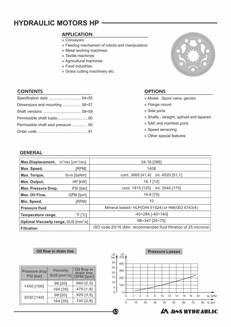
HYDRAULIC MOTORS HP
53
Pressure Losses
1450 [100]
2030 [140]
Pressure drop
PSI [bar]
Viscosity
SUS [mm /s]2
Oil flow indrain line
GPM [lpm]
98 [20]
164 [35]
98 [20]
164 [35]
.660 [2,5]
.476 [1,8]
.925 [3,5]
.740 [2,8]
Oil flow in drain line
Max.Displacement,
Max. Speed,
Max. Torque,
Max. Output,
Max. Pressure Drop,
Max. Oil Flow,
Min. Speed,
Pressure fluid
Temperature range,
Optimal Viscosity range,
Filtration
in /rev [cm /rev]
[RPM]
lb-in [daNm]
HP [kW]
PSI [bar]
GPM [lpm]
[RPM]
F [ C]
SUS [mm /s]
3 3
O O
2
24.16 [396]
1408
cont. 3665 [41,4] int. 4520 [51,1]
16.1 [12]
[ ]
19.8 [75]
10
Mineral based- HLP(DIN 51524) or HM(ISO 6743/4)
-40÷284 [-40÷140]
98÷347 [20÷75]
ISO code 20/16 (Min. recommended fluid filtration of 25 microns)
cont. 1815 125 int. 2540 [175]
GENERAL
7020 60504030100 Q, lpm
0 2 84 106 12 Q, GPM
80
0
100
200
400
300
0
5
10
15
20
25
pbar
pPSI
14 16 18 20
30
APPLICATION
» Conveyors
» Feeding mechanism of robots and manipulators
» Metal working machines
» Textile machines
achines
» Food industries
»
» A al mgricultur
etc.Grass cutting machinery
Specification data ......................... ..
Dimensions and mounting .........
Shaft versions ............................... ..
Permissible shaft seal pressure ..............
Order code ........................ .....................
... 54÷55
........ 56
.. 58
60
. 61
÷57
÷59
60Permissible shaft loads............................
CONTENTS OPTIONS
»
»
»
»
»
»
»
Model - Spool valve, gerotor
Flange mount
Side ports
Shafts - straight, splined and tapered
SAE and manifold ports
Speed sensoring
Other special features

SPECIFICATION DATA
54
HP
MOTORSMOTORS
Type
Displacement, in³/rev [cm³/rev]
Max. Speed,
[RPM]
Max. Torque
in [daNm]
Max. Output
HP [kW]
Max. Pressure Drop
PSI [bar]
Max. Oil Flow
GPM [lpm]
Max. Inlet Pressure
PSI [bar]
Max. Return Pres-
sure with Drain Line
PSI [bar]
Max. Starting Pressure with
Unloaded Shaft, PSI [bar]
Min. Starting Torque
[daNm]
Min. Speed***, [RPM]
Weight, lb [kg]
lb-
lb-in
Cont.
Int.*
Cont.
Int.*
Cont.
Int.*
Cont.
Int.*
Cont.
Int.*
Cont.
Int.*
Peak**
Cont.
Int.*
Peak**
At max.press. drop Cont.
At max.press. drop Int.*
HP
HPQ
Peak**
Peak**
3.02 [49,5]
7 [8, ]
0 [11, ]
11. [8, ]
1 [1 ]
1815 [125]
2540 [175]
[ ]
2030 [140]
2540 [175]
2030 [140]
2540 [175]
909
1111
17 1
99 2
1210 [13,7]
3 4
4.1 0,5
14.5 55
3260 [225]
11.9 4
3260 [225]
3260 [225]
[ 5]
4.83 [79,2]
75
94
1 [1 ]
1 [1 ]
11. [8, ]
1 [1 ]
1815 [125]
2540 [175]
1 [60]
[75]
2030 [140]
2540 [175]
2030 [140]
2540 [175]
8
7
141 2,9
585 7,9
1930 [21,8]
3 4
6 2
3260 [225]
5.9
19.8
3260 [225]
3260 [225]
6.04 [99,0]
60
75
1 [1 ]
[2 3]
11. [8, ]
1815 [125]
2540 [175]
2030 [140]
2540 [175]
2030 [140]
2540 [175]
6
8
434 6,2
1974 2,
2420 [27,3]
3 4
1 [1 ]
1 [60]
[75]
6 2
3260 [225]
5.9
19.8
3260 [225]
3260 [225]
HP 80HP 50HP 25 HP 32 HP 40 HP 100
145 [10]
6 [ ]
[10 ]
10
[5, ]
1 [ ]
55 7,4
900 ,2
11.7 3
0.8 4,9
104 [11, ]
14 0 [16, ]
10
[5, ]
11.25 [5,1]
5 8
4 3
11.9 4
13 0 [14, ]
18 0 [2 ]
10
[5, ]
11.69 [5,3]
0 7
0 0,3
12.3 6
2.4 [40 ]
1
5 5 [6, ]
7 ]
[ ]
1 .5 [ ,6]
7 ,5
900
110
7 5
95 [9,0
975 [11]
7.5 5,6
1 8
1815 [125]
2540 [175]
10.5 [40]
[ 5]
2030 [140]
2540 [175]
2030 [140]
2540 [175]
3260 [225]
11.9 4
3260 [225]
3260 [225]
1. [2 ]
290 [3,3]
4 [4, ]
0 [ ]
8.2 [6,1]
1450 [100]
2030 [140]
10.5 [40]
73 8,4
1055
1600
00 5
610 [6,9]
4.6 3,4
3260 [225]
8 [30]
2030 [140]
2540 [175]
2030 [140]
2540 [175]
3260 [225]
3260 [225]
[3 ]
1
1
78
[5, ]
[ ]
1 [1 ]
2 [1 0]
[ 5]
2.11 4,5
160
300
460 [5,2]
620 [7,0]
0 [8,8]
7.5 6
11.3 8,4
815 25
465 7
11.9
3260 [225]
4
3260 [225]
3260 [225]
10.5 [40]
2030 [140]
2540 [175]
2030 [140]
2540 [175]
265 [3,0]
3 [4, ]
20
11. [5, ]
10.6 [4,8]
62 1
5 2
425 8
65 6,4
[4, ]
5 [ ]
15
10.6 [4,8]
11. [5, ]5 2
566 6,4
725 8,2
6 8
[ ]
[ ]
10
10. [4, ]
11. [5, ]5 2
145 [10] 145 [10] 145 [10] 145 [10] 145 [10]
* Intermittent operation: the permissible values may occur for max. 10% of every minute.
** Peak load: the permissible values may occur for max. 1% of every minute.
*** For speeds lower than given, consult factory or your regional manager.
1. Intermittent speed and intermittent pressure drop must not occur simultaneously.
2. Recommended filtration is per ISO cleanliness code 20/16. A nominal filtration of 25 micron or better.
3. Recommend using a premium quality, anti-wear type mineral based hydraulic oil HM (ISO 6743/4).
If using synthetic fluids consult the factory for alternative seal materials.
4. Recommended minimum oil viscosity 70 SUS [13 mm²/s] at 122ºF [50ºC].
5. Recommended maximum system operating temperature is 180ºF [82ºC].
6. To assure optimum motor life fill with fluid prior to loading and run at moderate load and speed for 10-15 minutes.
HLP(DIN51524) or

55
HP
MOTORSMOTORS
Type
SPECIFICATION DATA (continued)
HP 125 HP 160 HP 200 HP 250 HP 315 HP 400
7.55 [123,8]
48
60
1 [2 ]
2 [2 ]
11. [8, ]
[1 ]
1815 [125]
2540 [175]
2030 [140]
2540 [175]
2030 [140]
2540 [175]
5
6
790 0,2
470 7,9
3025 [34,2]
3 4
16 2
3260 [225]
5.9
19.8
3260 [225]
3260 [225]
1 [60]
[75]
9.66 [158,4]
37
47
2 5 [2 ]
2 [3 ]
1 [ ]
1 [12]
2250 [155]
2030 [140]
2540 [175]
2030 [140]
2540 [175]
9
3
10 3,8
805 1,7
3870 [43,7]
0.3 7,7
6
1670 [115]
1 [60]
[75]
3260 [225]
5.9
19.8
3260 [225]
3260 [225]
12.1 [198]
303
37
2 [ ]
3 90 [3 ]
[7, ]
1 0 [1 5]
2175 [150]
2030 [140]
2540 [175]
2030 [140]
2540 [175]
9
400 27,1
3 8,3
4830 [54,6]
9.5 1
52 0
16 [12]
1 [60]
[75]
3260 [225]
5.9
19.8
3260 [225]
3260 [225]
15.1 [247,5]
242
303
2 0 [3 ]
3 [4 ,5]
9 [6,7]
1 3 [ ,7]
1450 [100]
18 5 [1 ]
2030 [140]
2540 [175]
2030 [140]
2540 [175]
86 2,3
675 1
4830 [54,6]
4. 10
8 30
2610 [180]
5.9
19.8
3260 [225]
3260 [225]
1 [60]
[75]
19.3 [316,8]
1
23
3 0 [3 ]
[4 ]
[ ]
[ ]
1 [ ]
1 0 [1 0]
2030 [140]
2540 [175]
2030 [140]
2540 [175]
89
7
29 7,2
4340 9,0
5500 [62,1]
8.2 6,1
13.1 9,8
305 90
74 2
2320 [160]
5.9
19.8
3260 [225]
3260 [225]
1 [60]
[75]
24.16 [396]
15
189
[ ]
[ ]
[ ]
[ ]
1160 [80]
2030 [140]
2540 [175]
2030 [140]
2540 [175]
2
3665 41,4
4520 51,1
5585 [63,1]
7.2 5,4
11 8,2
1450 [100]
18 5 [1 ]
1 [60]
[75]
8 30
5.9
19.8
3260 [225]
3260 [225]
100 [7] 100 [7] 100 [7] 100 [7]
1630 [18,4]
2 0 [2 ]
10
[ , ]
11.91 [5,4]
25 5,1
12.6 5 7
1910 1,6
55 28,8
0 5,9
[2 ]
2 0 [ ]
10
13. [ ]
12.35 [5,6]
2 0 [2 7]
3 0 [3 ]
10
[ ]
12.79 [5,8]
19 4,
09 4,9
13.4 6,1
2 00 [ ]
3 [37 ]
10
[6, ]
13.23 [6,0]
6 29,4
345 ,8
13.9 3
300 3,9
5 6
14.6 6
0 [3 ]
39 0 [44, ]
10
[6, ]
13.89 [6,3]
333 7,6
4115 6,5
15.7 1
14.8 7
0 [3 ]
[4 ]
10
[7, ]
[6, ]
145 [10] 145 [10]
* Intermittent operation: the permissible values may occur for max. 10% of every minute.
** Peak load: the permissible values may occur for max. 1% of every minute.
*** For speeds lower than given, consult factory or your regional manager.
1. Intermittent speed and intermittent pressure drop must not occur simultaneously.
2. Recommended filtration is per ISO cleanliness code 20/16. A nominal filtration of 25 micron or better.
3. Recommend using a premium quality, anti-wear type mineral based hydraulic oil HM (ISO 6743/4).
If using synthetic fluids consult the factory for alternative seal materials.
4. Recommended minimum oil viscosity 70 SUS [13 mm²/s] at 122ºF [50ºC].
5. Recommended maximum system operating temperature is 180ºF [82ºC].
6. To assure optimum motor life fill with fluid prior to loading and run at moderate load and speed for 10-15 minutes.
HLP(DIN51524) or
Displacement, in³/rev [cm³/rev]
Max. Speed,
[RPM]
Max. Torque
[daNm]
Max. Output
HP [kW]
Max. Pressure Drop
PSI [bar]
Max. Oil Flow
GPM [lpm]
Max. Inlet Pressure
PSI [bar]
Max. Return Pres-
sure with Drain Line
PSI [bar]
Max. Starting Pressure with
Unloaded Shaft, PSI [bar]
Min. Starting Torque
[daNm]
Min. Speed***, [RPM]
Weight, lb [kg]
lb-in
lb-in
Cont.
Int.*
Cont.
Int.*
Cont.
Int.*
Cont.
Int.*
Cont.
Int.*
Cont.
Int.*
Peak**
Cont.
Int.*
Peak**
At max.press. drop Cont.
At max.press. drop Int.*
HP
HPQ
Peak**
Peak**

56
HP
MOTORSMOTORS
DIMENSIONS AND MOUNTING DATA FOR HP
S Shaft
[41,8/41,4]
1.646/1.63
L1
Port B
Port A
max L
P(A,B)
T3.543 [90] Dia.
HP
T Shaft
G ShaftC Shaft
CL Shaft
CP Shaft
H ShaftM ShaftSL Shaft
2.185[55,5]max
2.165[55]max
2.047[52]max
1.992[50,6]max
2.205[56]max
CW Shaft
CH Shaft
1.811[46]max
max L
[41,8/41,4]
1.646/1.63
Port A
Port B
L1
P(A,B)
T3.543 [90] Dia.
SH Shaft
HP(Q) 25
HP(Q) 32
HP(Q) 40
HP(Q) 50
HP(Q) 80
HP(Q) 100
HP(Q) 125
HP(Q) 160
HP(Q) 200
HP(Q) 250
HP(Q) 315
HP(Q) 400
Type
4.69 [119,0]
4.72 [120,0]
4.76 [121,0]
4.74 [120,5]
4.90 [124,5]
5.00 [127,0]
5.14 [130,5]
5.32 [135,0]
5.53 [140,5]
5.79 [147,0]
6.16 [156,5]
6.57 [167,0]
L , in [mm]max
.21 [5,20]
.25 [6,30]
.29 [7,40]
.26 [6,67]
.42 [10,67]
.52 [13,33]
.66 [16,67]
.84 [21,33]
1.05 [26,67]
1.31 [33,33]
1.68 [42,67]
2.10 [53,33]
L , in [mm]1
Standard Rotation
A CWB CCW
Viewed from Shaft EndPort Pressurized -Port Pressurized -
Reverse Rotation
A CCWB CW
Viewed from Shaft EndPort Pressurized -Port Pressurized -
in [mm]
Flange Dim.See Page 57
Port Dim.See Page 57
Shaft Dim.See Page 58 and 59
HPQ

HP
MOTORSMOTORS
57
MOUNTING
PORTS
Side Ports
Standard Rotation
A CWB CCW
Viewed from Shaft EndPort Pressurized -Port Pressurized -
Reverse Rotation
A CCWB CW
Viewed from Shaft EndPort Pressurized -Port Pressurized -
in [mm]
SAE A Flange
Q - Square Flange
5
-
2x -14NPTF
-20UNF716/
4
-
2x -14UNF
-20UNF
78/
716/
4x -18UNC
2x.39 Dia. [2x10]
-20UNF716/
516/C
P
T
(A,B)
Versions
3
4x M8
2x.39 Dia. [2x10]
-20UNF716/
12/
2
2x
-
G1/2
G1/4
1
3.250/3.248[82,55/82,5]
Pilot Dia.
3.5[88,85]
Dia.
.081[2,05]
.598[15,2]
1.646/1.63[41,8/41,4]
.11/.094[2,8/2,4]
3.79 [96]
5.118
max[ ]130
1.779/1.756[45,2/44,6]
4.2/4.177 Dia.[106,7/106,1]
2x.534/.525[13,55/13,35]
Dia. Thru
1.646/1.63[41,8/41,4]
1.749/1.746[44,45/44,35]
Pilot Dia.
.11/.094[2,8/2,4]
.591 max[15]
4x3/8-16 UNC[4xM10 for Version 2]
3.465 [88] max
1.779/1.756[45,2/44,6]
3.254/3.246[82,65/82,45]
Dia.
3.228 [82] max
3.228[82]max
Version 1 , 3 Version 4 Version 2 , 5
2x.39 Dia.[2x10]
2x.688 Dia.[2x17,48]
.081/.077[2,05/1,95]
A-A
Port A
Port B
.898[22,8]
.563[14,3]
1.25[31,75]
C
A
A
1.25[31,75]
.898[22,8]
.563[14,3]
P(A,B)
.904/.892[22,95/22,65]
.904/.892[22,95/22,65]
Port A
Port B
P(A,B)
Port A
Port B
P(A,B)
.904/.892[22,95/22,65]
.904/.892[22,95/22,65]

58
SHAFT EXTENSIONS FOR HP AND HR MOTORS
1" [25,4] straight,
Max. Torque 3009 [34 daNm]
Woodruff key / ”x1" SAE J502
lb-in
1 4
C
1" [25,4], SAE 6B Splined
Max. Torque 3540 [40 daNm]lb-in
G
1" [25,4] straight, w/ .315 [8] Crosshole
Max. Torque 3009 [34 daNm]lb-in
H
13T Splined, " [22,2], ANS B 92.1-1976
Max. Torque 3200 [36 daNm]lb-in
/7 8
S
T
Requirement max. Torque must exceeded.not be
HP+HR
MOTORSMOTORS
/3 16 /3 16
1" [25,4], SAE J501 Tapered
Parallel
Max. Torque 3540 - [40 daNm]
key "x "x “
lb in
/3 4
in [mm]
1.124 Dia.
[28,56]
1.00/.999 Dia.
[25,4/25,38]
1.594/1.555 Dia.
[40,5/39,5]
.744/.713
[18,9/18,1]1.00/.99 Dia.
[25,4/25,375]
.251/.249
[6,375/6,35]
1.110/1.094
[28,2/27,8]
1/4-20 UNC
.629 [16] min Deep
.453/.429
[11,5/10,9]
1.00/.999 Dia.
[25,4/25,38]1.124 Dia.
[28,56]
1.831/1.791
[46,5/45,5]
.318/.312
[8,07/7,93]
Dia. Thru
1.124 Dia.
[28,56]
.998/.996 Dia.
[25,35/25,30]
1.00 min
[25,4]
1.594/1.555
[40,5/39,5].247/.244
[6,275/6,2]
.848/.843 Dia.
[21,54/21,40]
1/4-20 UNC
.629 [16] min Deep
1.124 Dia.
[28,56]
.945 min
[24]
1.594/1.555
[40,5/39,5].715/.695 Dia.
[18,16/17,64]
.875/.874 Dia.
[22,225/22,20]
1/4-20 UNC
.629 [16] min Deep
Nut 3/4-16UNF-2B1.063 [27] across flat
Tightening torque for Nut790÷970 lb-in [9÷11 daNm]
.161/.154 Dia.
[4,1/3,9]
1.124 Dia.
[28,56]
1.001/.999 Dia.
[25,425/25,375]
A
3/4-16 UNF
.15
[3,8].669
[17]
A
1.669 [42,4]
.187/.185
[4,76/4,71]
A-A
.089/.083
[2,25/2,1]
1.5 Taper per Foot
[cone 1:8]

59
SHAFT EXTENSIONS FOR HP AND HR MOTORS
HP+HR
MOTORSMOTORS
ø25 , Parallel key A8x7x32 DIN 6885
Max. Torque 3009 [34 daNm]
straight
lb-in
M
ø25 , Parallel key A8x7x32 DIN 6885
Max. Torque 3009 [34 daNm]
straight
lb-in
CP
1" [25,4] , Parallel key / "x / "x1 / " BS46
Max. Torque 3009 [34 daNm]
1 1 1
4 4 4straight
lb-in
CL
ø25 , Parallel key A8x7x32 DIN 6885
Max. Torque 3009 [34 daNm]
straight
lb-in
CW
ø25 /Woodruff key ”x1" SAE J502
lb-in
1
4straight,
Max. Torque 3009 [34 daNm]
CH
1" [25,4], SAE 6B Splined
Max. Torque 3540 [40 daNm]lb-in
SH
1" [25,4], SAE 6B Splined
Max. Torque 3540 lb-in [40 daNm]
SL
M8
.709 [18] min. deep
.315/.313
[8,00/7,964]
1.109/1.088
[27,99/27,64].984/.983 Dia.
[25,0/24,97]
1.772/1.732
[45,0/44,0]
1.124 Dia.
[28,56]
1.109/1.088
[27,99/27,64]
.315/.313
[8,00/7,964]
M8
.709 [18] min. deep
.985/.984 Dia.
[25,015/25,002]
1.948/1.909
[49,5/48,5]
1.124 Dia.
[28,56]
.252/.250
[6,40/6,35]
1.110/1.102
[28,2/28,0]
M8
.709 [18] min. deep
1.000/.999 Dia.
[25,4/25,375]
1.969/1.929
[50,0/49,0]
1.124 Dia.
[28,56]
.315/.313
[8,00/7,964]
1.109/1.088
[27,98/27,70]
M8
.709 [18] min. deep
1.102/.984 Dia.
[25,02/25,0]
1.594/1.555
[40,5/39,5]
1.124 Dia.
[28,56]
.251/.250
[6,375/6,35]
1.110/1.102
[28,2/28,0]
M8
.709 [18] min. deep
.984/.983 Dia.
[25,0/24,97]
.728
[18,5]
1.594/1.555
[40,5/39,5]
1.124 Dia.
[28,56]
Splined
SAE 6B, BS2059
.247/.244
[6,275/6,20]
.848/.843 Dia.
[21,54/21,40]
M8
.709 [18] min. deep
.998/.996 Dia.
[25,353/25,293]
1.124 Dia.
[28,56]
min 1
[25,4]
1.594/1.555
[40,5/39,5]
Splined
SAE 6B, BS2059
.247/.244
[6,275/6,20]
.848/.843 Dia.
[21,54/21,40]
M8
.709 [18] min. deep
1.949/1.909
[49,5/48,5]
.998/.996 Dia.
[25,353/25,293]
1.124 Dia.
[28,56]
min 1
[25,4]
Requirement max. Torque must exceeded.not be
in [mm]

PERMISSIBLE SHAFT LOADS FOR HP AND HR MOTORS
The permissible radial shaft load depends on the speed RPM and distance from the point of loadto the mounting flange.
Prad L
* - in inchL
RPM < 200 max Prad=1460 lbs [650 daN]�>
;RPM 200 < in.≥ L 2.2 [55 mm]
60
MOTORSMOTORS
200
300
400
500
600
700
0
100
0
400
800
1200
14601600
Prad
daN
Prad
lbs
200 400 600 800 1000
SAE A Flange
Q Flange
L=1.06 [27]
P max 330 lbs[150 daN]=a
P max 440 lbs[200 daN]=a
Prad
Prad
HP+HR
MAX. PERMISSIBLE SHAFT SEAL PRESSUREFOR HP AND HR MOTORS
HP...1 and HR...1 motorswithout drain connection:
The shaft seal pressure equalsthe average of input pressure
and return pressure.
HP... and HR... motorswith drain connection:
The shaft seal pressureequals the pressure in
the drain line.P = P +P
sealinput return
2
Max. return pressure without drain line ormax. pressure in the drain line
1460x ,lbs*
RPM 3. +
913
5 LRadial Shaft Load: Prad=
- continuous operations
- intermittent operations
0
50
100
150
200
0 200 400 600 800 1000 n, RPM
Pbar
0
500
1000
2000
PPSI
1500
2500
3000
Radial Shat Load Prad=650 23200
x ,daN*RPM 89+L
* - in mm.L
The shaft seal pressureequals the pressure
in the drain line.
HP... and HR...K K motorswith check valves
and drain connection:
HP... and HR...with check valves and
K1 K1 motors
without drain connection:
The shaft seal pressurenever exceeds the pressure
in the return line.
L=1.06 [27]

61
HP
MOTORSMOTORS
ORDER CODE
Pos.1
Pos.2
Pos.3
omit
Q
25
32
40
50
80
100
125
160
200
250
315
400
The hydraulic motors are mangano-phosphatized as standard.
H P
1 2 3 4 5 6 7 8
U
- side ports, Manifold [5/16-18 UNC Mounting
Threads], 7/16-20 UNF
- side ports, 2x 1/2,
- side ports, Manifold [M8 Mounting Threads],
7/16-20 UNF
- side ports, 2x7/8-14 UNF, O-ring, 7/16-20 UNF
- side ports, 2x1/2-14 NPTF, 7/16-20 UNF
G G1/4
Pos.9
omit
omit
1
Pos.7
Pos.5
Pos.8
U
Pos.6
omit
K
9
- Mounting Flange
- SAE A
- Square, four bolts
, two holes
- Displacement code*
- 1.73 in /rev [ 28,4 cm /rev]
- 2.11 in /rev [ 34,5 cm /rev]
- 2.47 in /rev [ 40,5 cm /rev]
- 3.02 in /rev [ 49,5 cm /rev]
- 4.83 in /rev [ 79,2 cm /rev]
- 6.04 in /rev [ 99,0 cm /rev]
- 9.66 in /rev [123,8 cm /rev]
- 9.74 in /rev [158,4 cm /rev]
- 12.10 in /rev [198,0 cm /rev]
- 15.10 in /rev [247,5 cm /rev]
- 19.30 in /rev [316,8 cm /rev]
- 24.16 in /rev [396,0 cm /rev]
3 3
3 3
3 3
3 3
3 3
3 3
3 3
3 3
3 3
3 3
3 3
3 3
- Shaft Extensions**
Pos.4 - Port Size/Type [standard manifold to each]
1
3
4
5
2
- Shaft Seal Version [see page ]60
- High pressure shaft seal
- Check Valves
- ithout check valves
- With check valves
W
- Drain Port
- Design Series
- Special Features [see page ]103
- with drain port
- without drain port
- Factory specified
C
G
H
S
T
M
CP
CL
CW
CH
SH
SL
- 1" [25,4] straight, Woodruff key
- 1" [25,4] SAE 6B Splined
- 1" [25,4] straight, w/.315 [8] Cross-hole
- / ” [22,2] 13T Splined78
- 1" [25,4] SAE J501 Tapered
- 25 straight,ø Parallel key A8x7x32 DIN 6885
- 25 straight,ø Parallel key A8x7x32 DIN 6885
- 1" [25,4] straight, Parallel key / "x / "x1 / " BS461 1 1
4 4 4
- 25 straight,ø Parallel key A8x7x32 DIN 6885
- 25 straight, Woodruff keyø / "x1" SAE J5021
4
- 1" [25,4], SAE 6B Splined
- 1" [25,4], SAE 6B Splined
*
**
For the please look at "M+S Hydraulic" Catalogue for MLHP motors, pages .
The permissible output torque for shafts must not be exceeded!
Function Diagrams 18÷24
Notes:

HYDRAULIC MOTORS HR
62
Pressure Losses
1450 [100]
2030 [140]
Pressure drop
PSI [bar]
Viscosity
SUS [mm /s]2
Oil flow indrain line
GPM [lpm]
98 [20]
164 [35]
98 [20]
164 [35]
.660 [2,5]
.476 [1,8]
.925 [3,5]
.740 [2,8]
Oil flow in drain line
7020 60504030100 Q, lpm
0 2 84 106 12 Q, GPM
80
0
100
200
400
300
0
5
10
15
20
25
pbar
pPSI
14 16 18 20
30
APPLICATION
Specification data ....................................
Dimensions and mounting ..................
Shaft versions ....................................
Order code ..............................................
63
64 65
58 59
60
60
66
÷
÷
Permissible shaft seal pressure...............
Permissible shaft loads.............................
CONTENTS OPTIONS
Max. Displacement,
Max. Speed,
Max. Torque,
Max. Output,
Max. Pressure Drop,
Max. Oil Flow,
Min. Speed,
Pressure fluid
Temperature range,
Optimal Viscosity range,
Filtration
in /rev [cm /rev]
[RPM]
lb-in [daNm]
HP [kW]
PSI [bar]
GPM [lpm]
[RPM]
F [ C]
SUS [mm /s]
3 3
O O
2
GENERAL
»
»
»
»
»
»
»
Model - Spool valve, roll-gerotor
Flange mount
Side ports
Shafts - straight, splined and tapered
SAE and manifold ports
Speed sensoring
Other special features
» Conveyors
» Feeding mechanism of robots and manipulators
» Metal working machines
» Textile machines
achines
» Food industries
»
» A al mgricultur
etc.Grass cutting machinery
23.56 [386]
971
cont. 3980 [45,0] int. 4560 [51,5]
16.2 [12,1]
[ ]
19.8 [75]
10
Mineral based- HLP(DIN 51524) or HM(ISO 6743/4)
-40÷284 [-40÷140]
98÷347 [20÷75]
ISO code 20/16 (Min. recommended fluid filtration of 25 microns)
cont. 2030 140 int. 2540 [175]
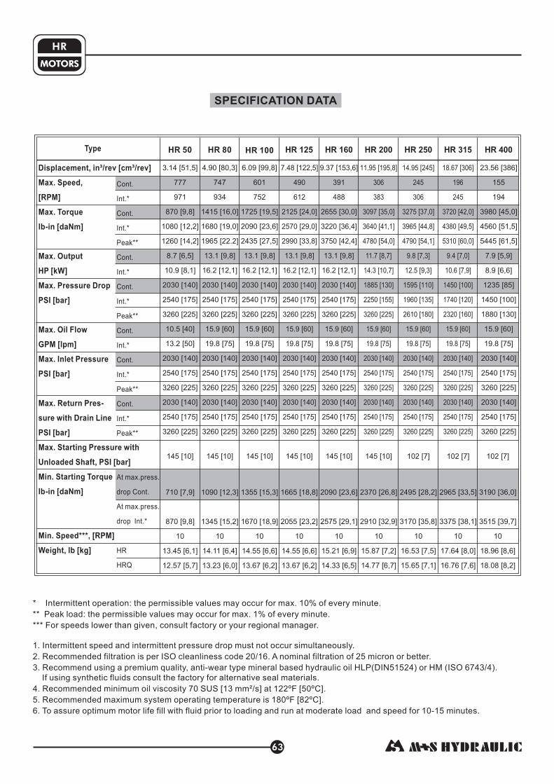
SPECIFICATION DATA
63
HR
MOTORSMOTORS
Type
Displacement, in³/rev [cm³/rev]
Max. Speed,
[RPM]
Max. Torque
- [daNm]
Max. Output
HP [kW]
Max. Pressure Drop
PSI [bar]
Max. Oil Flow
GPM [lpm]
Max. Inlet Pressure
PSI [bar]
Max. Return Pres-
sure with Drain Line
PSI [bar]
Max. Starting Pressure with
Unloaded Shaft, PSI [bar]
Min. Starting Torque
- [daNm]
Min. Speed***, [RPM]
Weight, lb [kg]
lb in
lb in
Cont.
Int.*
Cont.
Int.*
Cont.
Int.*
Cont.
Int.*
Cont.
Int.*
Cont.
Int.*
Peak**
Cont.
Int.*
Peak**
At max.press.
drop Cont.
At max.press.
drop Int.*
HR
HRQ
Peak**
Peak**
3.14 [51,5]
2030 [140]
2540 [175]
2030 [140]
2540 [175]
2030 [140]
2540 [175]
777
971
870 [9,8]
1080 [12,2]
1260 [14,2]
8.7 [6,5]
10.9 [8,1]
3260 [225]
10.5 [40]
13.2 [50]
3260 [225]
3260 [225]
4.90 [80,3]
2030 [140]
2540 [175]
1 [60]
[75]
2030 [140]
2540 [175]
2030 [140]
2540 [175]
747
934
1415 [16,0]
1680 [19,0]
1965 [22.2]
13.1 [9,8]
16.2 [12,1]
3260 [225]
5.9
19.8
3260 [225]
3260 [225]
6.09 [99,8]
2030 [140]
2540 [175]
2030 [140]
2540 [175]
2030 [140]
2540 [175]
601
752
1725 [19,5]
2090 [23,6]
2435 [27,5]
13.1 [9,8]
16.2 [12,1]
3260 [225]
5.9
19.8
3260 [225]
3260 [225]
1 [60]
[75]
7. [12 , ]
2030 [140]
2540 [175]
2030 [140]
2540 [175]
2030 [140]
2540 [175]
48 2 5
490
612
2125 [24,0]
2570 [29,0]
2990 [33,8]
13.1 [9,8]
16.2 [12,1]
3260 [225]
5.9
19.8
3260 [225]
3260 [225]
1 [60]
[75]
9. [15 ,6]
2030 [140]
2540 [175]
2030 [140]
2540 [175]
2030 [140]
2540 [175]
37 3
391
488
2655 [30,0]
3220 [36,4]
3750 [42,4]
13.1 [9,8]
16.2 [12,1]
3260 [225]
5.9
19.8
3260 [225]
3260 [225]
1 [60]
[75]
1 .9 [19 ,8]
[1 ]
2250 [155]
2030 [140]
2540 [175]
2030 [140]
2540 [175]
1 5 5
306
383
3097 [35,0]
3640 [41,1]
4780 [54,0]
11.7 [8,7]
14.3 [10,7]
1885 30
3260 [225]
5.9
19.8
3260 [225]
3260 [225]
1 [60]
[75]
[2 ]
15 [1 ]
2030 [140]
2540 [175]
2030 [140]
2540 [175]
14.95 45
245
306
3275 [37,0]
3965 [44,8]
4790 [54,1]
9.8 [7,3]
12.5 [9,3]
95 10
1960 [135]
2610 [180]
1 [60]
[75]
5.9
19.8
3260 [225]
3260 [225]
[3 ]
19
24
1450 [100]
1 [1 ]
2030 [140]
2540 [175]
2030 [140]
2540 [175]
18.67 06
6
5
3720 [42,0]
4380 [49,5]
5310 [60,0]
9.4 [7,0]
10.6 [7,9]
740 20
2320 [160]
1 [60]
[75]
5.9
19.8
3260 [225]
3260 [225]
[3 ]
15
19
2030 [140]
2540 [175]
2030 [140]
2540 [175]
23.56 86
5
4
3980 [45,0]
4560 [51,5]
5445 [61,5]
7.9 [5,9]
8.9 [6,6]
1235 [85]
1880 [130]
1450 [100]
1 [60]
[75]
5.9
19.8
3260 [225]
3260 [225]
HR 80HR 50 HR 100 HR 125 HR 160 HR 200 HR 250 HR 315 HR 400
145 [10] 145 [10] 145 [10] 145 [10] 145 [10] 145 [10] 102 [7] 102 [7] 102 [7]
710 [7,9]
870 [9,8]
13.45 1
12.57 5,7
10
[6, ]
[ ]
1090 [12,3]
1345 [15,2]
11 4
23 0
10
14. [6, ]
13. [6, ]
1355 [15,3]
1670 [18,9]
14.55 6,6
13.67 2
10
[ ]
[6, ]
1665 [18,8]
2055 [23,2]
10
14.55 6,6
13.67 2
[ ]
[6, ]
2090 [23,6]
2575 [29,1]
15.21 6,9
33 5
10
[ ]
14. [6, ]
2370 [26,8]
2910 [32,9]
15.87 2
14.77 6,7
10
[7, ]
[ ]
2495 [28,2]
3170 [35,8]
16.53 7,5
15.65 1
10
[ ]
[7, ]
2965 [33,5]
3375 [38,1]
17.64 0
16.76 7,6
10
[8, ]
[ ]
3190 [36,0]
3515 [39,7]
18.96 8,6
18.08 8,2
10
[ ]
[ ]
* Intermittent operation: the permissible values may occur for max. 10% of every minute.
** Peak load: the permissible values may occur for max. 1% of every minute.
*** For speeds lower than given, consult factory or your regional manager.
1. Intermittent speed and intermittent pressure drop must not occur simultaneously.
2. Recommended filtration is per ISO cleanliness code 20/16. A nominal filtration of 25 micron or better.
3. Recommend using a premium quality, anti-wear type mineral based hydraulic oil HM (ISO 6743/4).
If using synthetic fluids consult the factory for alternative seal materials.
4. Recommended minimum oil viscosity 70 SUS [13 mm²/s] at 122ºF [50ºC].
5. Recommended maximum system operating temperature is 180ºF [82ºC].
6. To assure optimum motor life fill with fluid prior to loading and run at moderate load and speed for 10-15 minutes.
HLP(DIN51524) or

[41,8/41,4]
1.646/1.63
maxL
Port BPort A
P(A,B)
T
L1
4.016 [102] Dia.
63
HR
MOTORSMOTORS
DIMENSIONS AND MOUNTING DATA FOR HR
HRQ
[41,8/41,4]
1.646/1.63
T
P(A,B)
Port B
Port A
L1
64
HR
MOTORSMOTORS
S ShaftT Shaft
G ShaftC Shaft
CL Shaft
CP Shaft
H ShaftM ShaftSL Shaft
2.185[55,5]max
2.165[55]max
2.047[52]max
.992[50,6]max
2.205[56]max
CW Shaft
CH Shaft
1.811[46]max
SH Shaft
HR
maxL
Shaft Dim.See Page 58 and 59
Flange Dim.See Page 65
Port Dim.See Page 65
HR(Q) 50
HR(Q) 80
HR(Q) 100
HR(Q) 125
HR(Q) 160
HR(Q) 200
HR(Q) 250
HR(Q) 315
HR(Q) 400
Type
4.85 [123,3]
5.05 [128,3]
5.19 [131,7]
5.19 [131,7]
5.36 [136,1]
5.59 [142,1]
5.87 [149,1]
6.21 [157,8]
6.66 [169,1]
L , in [mm]max L , in [mm]
.35 [9,0]
.55 [14,0]
.69 [17,4]
.86 [21,8]
1.09 [27,8]
1.37 [34,8]
1.71 [43,5]
2.16 [54,8]
1
.69 [17,4]
Standard Rotation
A CWB CCW
Viewed from Shaft EndPort Pressurized -Port Pressurized -
Reverse Rotation
A CCWB CW
Viewed from Shaft EndPort Pressurized -Port Pressurized -
in [mm]
4.016 [102] Dia.

HR
MOTORSMOTORS
65
MOUNTING
PORTS
Side Ports
Version 1 3,Version 4 Version 2 , 5
P(A,B).904/.892
[22,95/22,65]
.904/.892
[22,95/22,65]
in [mm]
Q - Square Flange
[41,8/41,4]
1.646/1.63
[44,45/44,35]1.749/1.746
Pilot Dia.
.11/.094[2,8/2,4]
.591 max[15]
1.779/1.756
[45,2/44,6]
4x3/8-16 UNC
3.254/3.246[82,65/82,45]
Dia.
max 3.228 [82]
[100]
3.937 max
max3.228[82]
[4xM10 for Version 2]
P(A,B)
5
-
2x -14NPTF
-20UNF716/
4
-
2x -14UNF
-20UNF
78/
716/
1
4x -18UNC
2x.39 Dia. [2x10]
-20UNF716/
516/C
P
T
(A,B)
Versions
3
4x M8
2x.39 Dia. [2x10]
-20UNF716/
12/
2
2x
-
G1/2
G1/4
[2x10]
2x.39 Dia.
.898[22,8]
[2x17,48]
2x.688 Dia.
.081/.077[2,05/1,95]
.563[14,3]
1.25[31,75]
P(A,B)
C
A
A
A-A
1.25[31,75]
.898[22,8]
.563[14,3]
SAE A Flange
3.250/3.248[82,55/82,5]
Pilot Dia.
3.5[88,85]
Dia.
.081[2,05]
.598[15,2]
[41,8/41,4]
1.646/1.63
.11/.094[2,8/2,4]
[ ]13,55/13,35
3.79 [96]
5.118
max[ ]130
[45,2/44,6]
1.779/1.756
3.937 max[100]
[106,7/106,1]
4.2/4.177 Dia.
2x.534/.525
Dia. Thru

HR
MOTORSMOTORS
66
ORDER CODE
Pos.1
Pos.2
Pos.3
omit
Q
50
80
100
125
160
200
250
315
400
The hydraulic motors are mangano-phosphatized as standard.
H R
1 2 3 4 5 6 7 8
U
- side ports, Manifold [5/16-18 UNC Mounting
Threads], 7/16-20 UNF
- side ports, 2x 1/2,
- side ports, Manifold [M8 Mounting Threads],
7/16-20 UNF
- side ports, 2x7/8-14 UNF, O-ring, 7/16-20 UNF
- side ports, 2x1/2-14 NPTF, 7/16-20 UNF
G G1/4
Pos.9
omit
omit
1
Pos.7
Pos.5
Pos.8
U
Pos.6
omit
K
9
- Mounting Flange
- SAE A
- Square, four bolts
, two holes
- Displacement code*
- 3. in /rev [ ,5 cm /rev]
- 4. in /rev [ , cm /rev]
- 6.0 in /rev [ 99, cm /rev]
- 48 in /rev [122,5 cm /rev]
- 9.37 in /rev [153, cm /rev]
- 11.95 in /rev [195, cm /rev]
- 14.95 in /rev [245,0 cm /rev]
- 18.67 in /rev [306,0 cm /rev]
- 23.56 in /rev [386,0 cm /rev]
14 51
90 80 3
9 8
7.
6
8
3 3
3 3
3 3
3 3
3 3
3 3
3 3
3 3
3 3
- Shaft Extensions** [see pages 58 and 59]
Pos.4 - Port Size/Type [standard manifold to each]
1
3
4
5
2
- Shaft Seal Version [see page ]60
- High pressure shaft seal
- Check Valves
- ithout check valves
- With check valves
W
- Drain Port
- Design Series
- Special Features [see page ]103
- with drain port
- without drain port
- Factory specified
C
G
H
S
T
M
CP
CL
CW
CH
SH
SL
- 1" [25,4] straight, Woodruff key
- 1" [25,4] SAE 6B Splined
- 1" [25,4] straight, w/.315 [8] Cross-hole
- / ” [22,2] 13T Splined78
- 1" [25,4] SAE J501 Tapered
- 25 straight,ø Parallel key A8x7x32 DIN 6885
- 25 straight,ø Parallel key A8x7x32 DIN 6885
- 1" [25,4] straight, Parallel key / "x / "x1 / " BS461 1 1
4 4 4
- 25 straight,ø Parallel key A8x7x32 DIN 6885
- 25 straight, Woodruff keyø / "x1" SAE J5021
4
- 1" [25,4], SAE 6B Splined
- 1" [25,4], SAE 6B Splined
*
**
For the please look at "M+S Hydraulic" Catalogue for MLH motors, pages 36 0.
The permissible output torque for shafts must not be exceeded!
Function Diagrams R ÷4
Notes:

HYDRAULIC MOTORS MLHRW
67
Pressure Losses
1450 [100]
2030 [140]
Pressure drop
PSI [bar]
Viscosity
SUS [mm /s]2
Oil flow indrain line
GPM [lpm]
98 [20]
164 [35]
98 [20]
164 [35]
.660 [2,5]
.476 [1,8]
.925 [3,5]
.740 [2,8]
Oil flow in drain line
7020 60504030100 Q, lpm
0 2 84 106 12 Q, GPM
80
0
100
200
400
300
0
5
10
15
20
25
pbar
pPSI
14 16 18 20
30
Specification data ............................ 68
Function diagrams ..................... 69÷73
Dimensions and mounting .............. 74
Permissible shaft Seal Pressure ..... 75
Permissible shaft loads .................. 75
Shaft extensions .............................. 76
Order code ....................................... 76
CONTENTS OPTIONS
APPLICATION»
»
»
»
»
»
Conveyors
Feeding mechanism of robots andmanipulators
Metal working machines
Textile machines
Food industries
» Agricultural machines
etc.Grass cutting machinery
»
»
»
»
»
Model - Spool valve, roll-gerotor
Wheel mount
Shafts - straight and tapered
Shaft seal for high and low pressure
SAE, Metric and BSPP ports
Other special features
»
Max. Displacement,
Max. Speed,
Max. Torque,
Max. Output,
Max. Pressure Drop,
Max. Oil Flow,
Min. Speed,
Pressure fluid
Temperature range,
Optimal Viscosity range,
Filtration
in /rev [cm /rev]
[RPM]
lb-in [daNm]
HP [kW]
PSI [bar]
GPM [lpm]
[RPM]
F [ C]
SUS [mm /s]
3 3
O O
2
24.4 397
5400 61 6100 69
20.1 15
2540 175 2900 200
23.8 90
-40÷284 [-40÷140]
98÷347 20÷75
[ ]
1029
cont.: [ ] int.: [ ]
[ ]
cont.: [ ] int.: [ ]
[ ]
10
Mineral based- HLP(DIN 51524) or HM(ISO 6743/4)
[ ]
ISO code 20/16 (Min. recommended fluid filtration of 25 microns)
GENERAL

68
MOTORS
MLHRW
Type
Displacement, in³/rev
[cm³/rev]
Max. Speed,
[RPM]
Max. Torque
in [daNm]
Max. Output
HP [kW]
Max. Pressure Drop
PSI [bar]
Max. Oil Flow
GPM [lpm]
Max. Inlet Pressure
PSI [bar]
Max. Return Pres-
sure with Drain Line
PSI [bar]
Max. Starting Pressure with
Unloaded Shaft, PSI [bar]
Min. Starting Torque
[daNm]
Min. Speed***, [RPM]
Weight, lb [kg]
lb-
lb-in
Cont.
Int.*
Cont.
Int.*
Peak**
Cont.
Int.*
Cont.
Int.*
Peak**
Cont.
Int.*
Cont.
Int.*
Peak**
Cont.
Int.*
Peak**
At max.press.
drop Cont.
At max.press.
drop Int.*
MLHRW
50
MLHRW
80
MLHRW
100
MLHRW
125
MLHRW
160
MLHRW
200
MLHRW
250
MLHRW
315
MLHRW
400
9.74
[159,6]
375
470
3450 [39]
3805 [43]
4070 [46]
15.4 [11,5]
18.8 [14]
2540 [175]
2900 [200]
3260 [225]
2540 [175]
2900 [200]
3260 [225]
2540 [175]
2900 [200]
3260 [225]
102 [7]
2832 [32]
3275 [37]
7
22.7
[10,3]
15.9 [60]
19.8 [75]
4. 0
[80,3]
750
940
1770 [20]
1947 [22]
2390 [27]
17 [12,5]
20.1 [15]
2540 [175]
2900 [200]
3260 [225]
15.9 [60]
19.8 [75]
2540 [175]
2900 [200]
3260 [225]
2540 [175]
2900 [200]
3260 [225]
145 [10]
1330 [15]
1505 [17]
10
21.4
[9,7]
93.14
[51,5]
775
1029
900 [10]
1150 [13]
1505 [17]
9.5 [7]
11.9 [8,5]
2030 [140]
2540 [175]
3260 [225]
11 [40]
13 [50]
2540 [175]
2900 [200]
3260 [225]
2540 [175]
2900 [200]
3260 [225]
145 [10]
710 [8]
885 [10]
10
21.2
[9,6]
7.67
[125,7]
475
600
2655 [30]
3010 [34]
3275 [37]
16.8 [12,5]
19.5 [14,5]
2540 [175]
2900 [200]
3260 [225]
2540 [175]
2900 [200]
3260 [225]
2540 [175]
2900 [200]
3260 [225]
130 [9]
2215 [25]
2480 [28]
9
22.1
[10,0]
15.9 [60]
19.8 [75]
6.09
[99,8]
600
750
2125 [24]
2480 [28]
2832 [32]
17.4 [13]
20.1 [15]
2540 [175]
2900 [200]
3260 [225]
2540 [175]
2900 [200]
3260 [225]
2540 [175]
2900 [200]
3260 [225]
145 [10]
1770 [20]
2035 [23]
10
21.7
[9,8]
15.9 [60]
19.8 [75]
12.19
[199,8]
300
375
4000 [45]
4425 [50]
4960 [56]
14.8 [11]
17.4 [13]
2540 [175]
2900 [200]
3260 [225]
2540 [175]
2900 [200]
3260 [225]
2540 [175]
2900 [200]
3260 [225]
73 [5]
3630 [41]
4070 [46]
5
23.8
[10,8]
15.9 [60]
19.8 [75]
15.26
[250,1]
300
360
4780 [54]
5400 [61]
6280 [71]
13.4 [10]
16.1 [12]
2540 [175]
2900 [200]
3260 [225]
2540 [175]
2900 [200]
3260 [225]
2540 [175]
2900 [200]
3260 [225]
4425 [50]
4870 [55]
6
24.9
[11,3]
19.8 [75]
23.8 [90]
73 [5]
19.26
[315,7]
240
285
4870 [55]
5580 [63]
7350 [83]
12 [9]
14.8 [11]
1960 [135]
2320 [160]
3045 [210]
2540 [175]
2900 [200]
3260 [225]
2540 [175]
2900 [200]
3260 [225]
5840 [66]
5
26
[11,8]
19.8 [75]
23.8 [90]
73 [5]
4425 [50]
24.4
[397]
190
226
5400 [61]
6100 [69]
7700 [87]
10.5 [7,8]
14.2 [10,6]
1600 [110]
2030 [140]
2540 [175]
2540 [175]
2900 [200]
3260 [225]
2540 [175]
2900 [200]
3260 [225]
5400 [61]
5
27.63
[12,5]
19.8 [75]
23.8 [90]
73 [5]
4425 [50]
SPECIFICATION DATA
* Intermittent operation: the permissible values may occur for max. 10% of every minute.
** Peak load: the permissible values may occur for max. 1% of every minute.
*** For speeds lower than given, consult factory or your regional manager.
1. Intermittent speed and intermittent pressure drop must not occur simultaneously.
2. Recommended filtration is per ISO cleanliness code 20/16. A nominal filtration of 25 micron or better.
3. Recommend using a premium quality, anti-wear type mineral based hydraulic oil HM (ISO 6743/4).
If using synthetic fluids consult the factory for alternative seal materials.
4. Recommended minimum oil viscosity 70 SUS [13 mm²/s] at 122ºF [50ºC].
5. Recommended maximum system operating temperature is 180ºF [82ºC].
6. To assure optimum motor life fill with fluid prior to loading and run at moderate load and speed for 10-15 minutes.
HLP(DIN51524) or

MLHRW 50
MLHRW 80
FUNCTION DIAGRAMS
0,5kW
1kW
2kW
6kW
4kW
8kW
MdaNm
0
2
4
6
8
10
12
14
16
18
20
0
Mlb-in
200
400
600
800
1600
1000
1200
1400
1800
222000
70 bar1020 PSI
50 bar730 PSI
n
cont.
int.
cont. int.
p=175 bar2540 PSI
140 bar2030 PSI
MdaNm
0
1
2
3
4
5
Mlb-in
6
7
8
9
10
11
12
0 RPM400200 600 800700 900100 300 500 1000
120 bar1740 PSI
30 bar430 PSI
100 bar1450 PSI
20 l/m
in5.3
GP
M
30 l/m
in7.9
GP
M
40 l/m
in10.6
GP
M
35 l/m
in9.2
GP
M
10 l/m
in2.6
GP
M
50 l/m
in13.2
GP
M
Q=
5 l/m
in1.3
GP
M
45 l/m
in11.9
GP
M
25 l/m
in6.6
GP
M
15 l/m
in4.0
GP
M
20 l/m
in5.3
GP
M
30 l/m
in7.9
GP
M
40 l/m
in10.6
GP
M
10 l/m
in2.6
GP
M
50 l/m
in13.2
GP
M
70 l/m
in18.5
GP
M
60 l/m
in15.9
GP
M
Q=
5 l/m
in1.3
GP
M
75 l/m
in19.8
GP
M
0
100
200
300
400
500
600
700
800
900
1000
1100
0 RPM400200 600 800700 900100 300 500
ncont. int.
p=200 bar2900 PSI
80 bar1160 PSI
60 bar870 PSI
30 bar430 PSI
100 bar1450 PSI
140 bar2030 PSI
120 bar1740 PSI
175 bar2540 PSI
MOTORS
MLHRW
69
The function diagrams data is for average performance of randomly selected motors at back pressure[ ] and oil with viscosity of [ ] at [ ].72.5÷145 PSI 5÷10 bar 150 SUS 32 mm²/s 122 F 50°C
o

MLHRW 100
MLHRW 125
FUNCTION DIAGRAMS
0
800
1200
1600
2000
2400
400
2800
3200
MdaNm
0 RPM
n
cont.
int.
cont. int.
400200 600
20 l/m
in5.3
GP
M
30 l/m
in7.9
GP
M
40 l/m
in10.6
GP
M
10 l/m
in2.6
GP
M
50 l/m
in13.2
GP
M
70 l/m
in18.5
GP
M
60 l/m
in15.9
GP
M
Q=
5 l/m
in1.3
GP
M
75 l/m
in19.8
GP
M
100 300 500
0
4
8
12
16
20
0
Mlb-in
500
1000
1500
24
2000
282500
700
p=200 bar2900 PSI
80 bar1160 PSI
60 bar870 PSI
30 bar430 PSI
100 bar1450 PSI
140 bar2030 PSI
120 bar1740 PSI
175 bar2540 PSI
MdaNm
0 RPM
n
cont.
int.
cont. int.
400200 600
20 l/m
in5.3
GP
M
30 l/m
in7.9
GP
M
40 l/m
in10.6
GP
M
10 l/m
in2.6
GP
M
50 l/m
in13.2
GP
M
70 l/m
in18.5
GP
M
60 l/m
in15.9
GP
M
Q=
5 l/m
in1.3
GP
M
75 l/m
in19.8
GP
M
100 300 500
0
4
8
12
16
20
Mlb-in
24
32 p=200 bar2900 PSI
80 bar1160 PSI
60 bar870 PSI
30 bar430 PSI
100 bar1450 PSI
140 bar2030 PSI
120 bar1740 PSI
175 bar2540 PSI
28
36
MOTORS
MLHRW
70
The function diagrams data is for average performance of randomly selected motors at back pressure[ ] and oil with viscosity of [ ] at [ ].72.5÷145 PSI 5÷10 bar 150 SUS 32 mm²/s 122 F 50°C
o

MLHRW 160
MLHRW 200
FUNCTION DIAGRAMS
MdaNm
RPM
n
cont.
int.
cont. int.
20 l/m
in5.3
GP
M
30 l/m
in7.9
GP
M
40 l/m
in10.6
GP
M
10 l/m
in2.6
GP
M
50 l/m
in13.2
GP
M
70 l/m
in18.5
GP
M
60 l/m
in15.9
GP
M
Q=
5 l/m
in1.3
GP
M
75 l/m
in19.8
GP
M
0
4
8
12
16
20
24
32
p=200 bar2900 PSI
80 bar1160 PSI
60 bar870 PSI
30 bar430 PSI
100 bar1450 PSI
140 bar2030 PSI
120 bar1740 PSI
175 bar2540 PSI
28
36
40
44
MdaNm
RPM
n
cont.
int.
cont. int.
20 l/m
in5.3
GP
M
30 l/m
in7.9
GP
M
40 l/m
in10.6
GP
M
10 l/m
in2.6
GP
M
50 l/m
in13.2
GP
M
70 l/m
in18.5
GP
M
60 l/m
in15.9
GP
M
Q=
5 l/m
in1.3
GP
M
75 l/m
in19.8
GP
M
Mlb-in
p=200 bar2900 PSI
80 bar1160 PSI
60 bar870 PSI
30 bar430 PSI
105 bar1520 PSI
140 bar2030 PSI
120 bar1740 PSI
175 bar2540 PSI
0
800
1200
1600
2000
2400
400
2800
3200
Mlb-in
3600
4000
0 400200100 300 450250150 35050
0
5
10
15
20
25
0
1000
1500
2000
302500
353000
40
45
500
3500
4000
4500 50
0 200100 300250150 35050
MOTORS
MLHRW
71
The function diagrams data is for average performance of randomly selected motors at back pressure[ ] and oil with viscosity of [ ] at [ ].72.5÷145 PSI 5÷10 bar 150 SUS 32 mm²/s 122 F 50°C
o

MLHRW 250
MLHRW 315
FUNCTION DIAGRAMS
35
MdaNm
0
5
10
15
20
25
Mlb-in
30
40
45
50
55
60
65
0
1000
1500
2000
2500
3000
500
3500
4000
4500
5000
5500
6000
RPM0 200100 2251505025 75 125 175 250 300275
0
8
16
24
32
40
48
56
72
64
n
cont.
int.
cont. int.
20 l/m
in5.3
GP
M
30 l/m
in7.9
GP
M
40 l/m
in10.6
GP
M
10 l/m
in2.6
GP
M
50 l/m
in13.2
GP
M
70 l/m
in18.5
GP
M
60 l/m
in15.9
GP
M
Q=
5 l/m
in1.3
GP
M
75 l/m
in19.8
GP
M
p=200 bar2900 PSI
80 bar1160 PSI
60 bar870 PSI
30 bar430 PSI
105 bar1520 PSI
140 bar2030 PSI
175 bar2540 PSI
110 bar1600 PSI
ncont. int.
20 l/m
in5.3
GP
M
30 l/m
in7.9
GP
M
40 l/m
in10.6
GP
M
10 l/m
in2.6
GP
M
50 l/m
in13.2
GP
M
70 l/m
in18.5
GP
M
60 l/m
in15.9
GP
M
Q=
5 l/m
in1.3
GP
M
75 l/m
in19.8
GP
M
p=175 bar2540 PSI
135 bar1740 PSI
30 bar430 PSI
160 bar2320 PSI
80 bar1160 PSI
cont.
int.
0
1000
1500
2000
2500
3000
500
3500
4000
4500
5000
5500
6000
6500
0 200100 2251505025 75 125 175 RPM
MdaNm
Mlb-in
65 bar940 PSI
45 bar650 PSI
125 bar1810 PSI
350 375325
90 l/m
in23.8
GP
M
250 275 300
90 l/m
in23.8
GP
M
MOTORS
MLHRW
72
The function diagrams data is for average performance of randomly selected motors at back pressure[ ] and oil with viscosity of [ ] at [ ].72.5÷145 PSI 5÷10 bar 150 SUS 32 mm²/s 122 F 50°C
o

MLHRW 400
FUNCTION DIAGRAMS
20 l/m
in5.3
GP
M
30 l/m
in7.9
GP
M
40 l/m
in10.6
GP
M
10 l/m
in2.6
GP
M
50 l/m
in13.2
GP
M
70 l/m
in18.5
GP
M
60 l/m
in15.9
GP
M
Q=
5 l/m
in1
.3 G
PM
75 l/m
in19.8
GP
M
MdaNm
0
4
8
12
16
20
24
32
28
36
40
44
0
800
1200
1600
2000
2400
400
2800
3200
Mlb-in
3600
4000
48
52
56
60
64
4400
4800
5200
5600
RPM
ncont. int.
100 20 30 5040 60 70 9080 100 110 120 130 140 150 160 170 180 190
15 l/m
in4.0
GP
M
p=125 bar1810 PSI
65 bar940 PSI
40 bar580 PSI
30 bar430 PSI
80 bar1160 PSI
90 bar1300 PSI
110 bar1600 PSI
55 bar800 PSI
200 210 220 230
90 l/m
in23.8
GP
M
MOTORS
MLHRW
73
The function diagrams data is for average performance of randomly selected motors at back pressure[ ] and oil with viscosity of [ ] at [ ].72.5÷145 PSI 5÷10 bar 150 SUS 32 mm²/s 122 F 50°C
o

MOTORS
MLHRW
DIMENSIONS AND MOUNTING DATA - MLHRW (WHEEL MOTOR)
74
Standard Rotation
CWCCW
Viewed from Shaft EndPort A Pressurized -Port B Pressurized -
Reverse Rotation
CCWCW
Viewed from Shaft EndPort A Pressurized -Port B Pressurized -
2
2xG½
G¼
4
2x -14UNF
-20UNF
P
T
(A,B)
Versions
78/
716/
5.118 [130]
1.862/1.846[47,3/46,9]
5.00/4.998 Dia.[127,0/126,96]
4x .539/.528[13,7/13,3]Dia. Thru
5.819/5.803 Dia.[147,8/147,4]
5.197[132]
2.5 [64]
3.250/3.248 Pilot Dia.[82,55/82,50]
3.94 [100] Dia.
MLHRW 50
MLHRW 80
MLHRW 100
MLHRW 125
MLHRW 160
MLHRW 200
MLHRW 250
MLHRW 315
MLHRW 400
L , in [mm]max L , in [mm]
.35 [9,0]
.55 [14,0]
.69 [17,4]
.86 [21,8]
1.09 [27,8]
1.37 [34,8]
1.71 [43,5]
2.16 [54,8]
2.73 [69,4]
1Type
4.25 [108,0]
4.45 [113,0]
4.59 [116,5]
4.74 [120,5]
4.98 [126,5]
5.26 [133,5]
5.61 [142,5]
6.04 [153,5]
6.63 [168,5]
T
[10,5/9,5]
.413/.374
[9,4/8,9]
.37/.35
[37,1/36,9]1.461/1.453
Port A Port B
4 21107.
[ ]max
[18,7/18,3]
.736/.72
P(A,B)
max L
L1
K Shaft
R Shaft
45o
Shaft Dim.See Page 76
in [mm]
2.295/2.271[58,3/57,7]
[48,3/47,7]1.902/1.878
3 81997.[ ]max
.911/.900[23,15/22,85]
.911/.900[23,15/22,85]

MAX. PERMISSIBLE SHAFT SEAL PRESSURE
MLHRW...1 motorswithout drain connection:
The shaft seal pressurenever exceeds the pressure
in the return line.
The shaft seal pressureequals the pressure
in the drain line.
MLHRW MLHRW...UK...; motorswith drain connection:
PERMISSIBLE SHAFT LOADS MLHRW
MOTORS
MLHRW
75
- continuous operations
- intermittent operations
1. Permissible radial shaft load2. Drawing by n= 50 RPM3. Drawing by n=100 RPM4. Drawing by n=200 RPM5. Drawing by n=400 RPM
The curve applies to a B10 bearing life of 2000 hours.
1: Drawing for Standard Shaft Seal
2: Drawing for High Pressure Seal ("U" Seal)
Max. return pressure without drain line ormax. pressure in the drain line
MLHRW...U motors with high pressureseal and drain connection:
The shaft seal pressureequals the pressure
in the drain line.
1
2
3
4
5
0
1000
2000
3000
PrdaN
1 005
2 005
3 005
500
2000
4000
6000
Pradlbs
100120 80 60 40 20 0 -20mm
012345 -2 in.
00 daN675 lbs.3
00 daN675 lbs.3
1000
3000
5000
7000
2
1

76
MLHRW
ORDER CODE
1 2 3 4 5 6
The hydraulic motors are mangano-phosphatized as standard.
Pos.1
Pos.2
50
80
100
125
160
200
250
315
400
- 3.14
- 4.90
- 6.09
- 7.67
- 9.74
- 12.19
- 15.26
- 19.26
- 24.40
in /r
in /r
in /r
in /r
in /r
in /r
in /r
in /r
in /r
3
3
3
3
3
3
3
3
3
K
R
Pos.7
omit
omit
1
Pos.5
Pos.6
SHAFT EXTENSIONS
/5 16/5 16
1¼" [31,75],SAE J501 Tapered
Parallel key "x "x1"
Max. Torque 6815 [77 daNm]lb-in
R
MOTORS
MLHRW
Requirement max. Torque
must be not exceeded.
Pos.4
omit
U
UK
/5 16/5 161¼" [31,75] , Parallel key "x "x1¼" BS 46
Max. Torque 6815 [77 daNm]
straight
lb-in
K
in [mm]
1.902/1.878
[48,3/47,7]
3/8-16 UNC.63
[16]
1.250/1.24 Dia.
[31,75/31,7]
8
.
[
313/.312
7,96/7,94]
1. /1.
[ / ]
391 381
35,33 35,081. Dia.
[35]
378
450
Tightening torque for Nut
1680 860 - [20±1 daNm]÷1 lb in
1.5 Taper per Foot
[cone 1:8]
2.2
[58 ]
95/2.27
,3/57,7
.156 Dia.
[4,0]
Nut 1-20 UNEF
1 / " [36,5] across flat7 16
.787
[20]
1.251/1.249 Dia.
[31,775/31,725].244/.228
[6,2/5,8]
1-20 UNEF1. Dia.
[35]
378
1.378
[35]
A
A
.
[
313/.312
7,96/7,94]
.
[
156/.152
3,96/3,86]
A - A
450
- Displacement code
- 3.14 [ 51,5 cm /rev]
- 4.90 [ 80,3 cm /rev]
- 6.09 [ 99,8 cm /rev]
- 7.67 [125,7 cm /rev]
- 9.74 [159,6 cm /rev]
- 12.19 [199,8 cm /rev]
- 15.26 [250,1 cm /rev]
- 19.26 [315,7 cm /rev]
- 24.40 [397,0 cm /rev]
3
3
3
3
3
3
3
3
3
in /rev
in /rev
in /rev
in /rev
in /rev
in /rev
in /rev
in /rev
in /rev
3
3
3
3
3
3
3
3
3
- Shaft Extensions*
- 1¼" [31,75] straight, Parallel key
- 1¼" [31,75] SAE J501 Tapered
2
4
Pos.3 - [standard manifold to each]Port Size/Type
- side ports, 2xG1/2, G1/4, BSP thread, ISO 228
- side ports, 2x7/8-14 UNF, O-ring, 7/16-20 UNF
- Shaft Seal Version
-
- High pressure shaft seal without check valves
- High pressure shaft seal with check valves
Standard shaft seal
- Drain Port
- with drain port
- without drain port
- Special Features [see page 103]
- Design Series
- Factory specified
* The permissible output torque for shafts must not be exceeded!
Notes:

Pressure Losses
HYDRAULIC MOTORS MLHH
77
0 6 12 182 8 14 204 10 16 22 24GPM0
6
12
2
8
14
4
10
1618
0
50
100
150
200
250
0 4020 60 8010 5030 70 90 lpm
Specification data ........................ 78
................. 79÷81
Dimensions and mounting........... 82
Permissible shaft seal pressure....83
Shaft extensions ......................... 84
Order code ................................. 84
Function diagrams
Permissible shaft loads .............. 81
CONTENTS OPTIONS
»
»
»
»
»
»
Model - Spool valve, roll-gerotor
Flange mount
Shafts - straight, splined and tapered
SAE, Metric and BSPP ports
Speed sensoring
Other special features
1450 [100]
2030 [140]
Pressure drop
PSI [bar]
Viscosity
SUS [mm /s]2
Oil flow indrain line
GPM [lpm]
98 [20]
164 [35]
98 [20]
164 [35]
.660 [2,5]
.476 [1,8]
.925 [3,5]
.740 [2,8]
Oil flow in drain line
APPLICATION»
»
»
»
»
»
»
Conveyors
Feeding mechanism of robots and manipulators
Metal working machines
Textile machines
Food industries
Agricultural machines
Mining machinery etc.
Max. Displacement,
Max. Speed,
Max. Torque,
Max. Output,
Max. Pressure Drop,
Max. Oil Flow,
Min. Speed,
Pressure fluid
Temperature range,
Optimal Viscosity range,
Filtration
in /rev [cm /rev]
[RPM]
lb-in [daNm]
HP [kW]
PSI [bar]
GPM [lpm]
[RPM]
F [ C]
SUS [mm /s]
3 3
O O
2
30.7 502,4
7434 84 9204 104
24.8 18,5
2540 175 2900 200
23.9 90
-40÷284 [-40÷140]
98÷347 20÷75
[ ]
445
cont.: [ ] int.: [ ]
[ ]
cont.: [ ] int.: [ ]
[ ]
5
Mineral based- HLP(DIN 51524) or HM(ISO 6743/4)
[ ]
ISO code 20/16 (Min. recommended fluid filtration of 25 microns)
GENERAL

SPECIFICATION DATA
* operation: the permissible values may occur for max. 10% of every minute.
** Peak load: the permissible values may occur for max. 1% of every minute.
*** For speeds lower than given, consult factory or your regional manager.
Intermittent
1) Intermittent speed and intermittent pressure must not occur simultaneously.
2) Recommended filtration is per ISO cleanliness code 20/16. A nominal filtration of 25 micron or better.
3) Recommend using a premium quality, anti-wear type mineral based hydraulic oil, HLP(DIN51524) or HM(ISO6743/4).
4) Recommended minimum oil viscosity 70 SUS [13 mm²/s] at 122ºF [50ºC].
5) Recommended maximum system operating temperature is 180ºF [82ºC].
6) To assure optimum motor life fill with fluid prior to loading and run at moderate load and speed for 10-15 minutes.
If using synthetic fluids consult the factory for alternative seal materials.
78
Type
Cont.
Int.*
Cont.
Int.*
Peak**
Cont.
Int.*
Cont.
Int.*
Peak**
Cont.
Int.*
Cont.
Int.*
Peak**
At max.press.dropCont
At max.press.drop Int.*
MLHH
200
15.4 [252]
295
350
5398 [61]
6195 [70]
6992 [79]
21 [16]
24.8 [18,5]
2540 [175]
2900 [200]
3260 [225]
2900 [200]
3260 [225]
3626 [250]
72 [5]
4600 [52]
5221 [59]
10
24.3 [11]
19.8 [75]
23.9 [90]
MLHH
250
MLHH
315
19.2 [314,9]
235
285
6548 [74]
7257 [82]
8673 [98]
18.7 [14]
20.7 [15,5]
2540 [175]
2900 [200]
3260 [225]
2900 [200]
3260 [225]
3626 [250]
72 [5]
5840 [66]
6460 [73]
8
25.4 [11,5]
19.8 [75]
23.9 [90]
Displacement, in³/rev [cm³/rev]
Max. Speed,
[RPM]
Max. Torque
- [daNm]
Max. Output
HP [kW]
Max. Pressure
Drop
PSI [bar]
Max. Oil Flow
GPM [lpm]
Max. Inlet Pressure
PSI [bar]
Max. Starting Pressure with
Unloaded Shaft, PSI [bar]
Min. Starting Torque,
in-lb [daNm]
Min. Speed***, [RPM]
Weight, lb [kg]
lb in
12.3 [201,3]
370
445
4510 [51]
5130 [58]
5064 [64]
21 [16]
24.8 [18,5]
2540 [175]
2900 [200]
3260 [225]
19.8 [75]
23.9 [90]
2900 [200]
3260 [225]
3626 [250]
72 [5]
3450 [39]
3980 [45]
10
23.2 [10,5]
MLHH
400
MLHH
500
30.7 [502,4]
150
180
7257 [82]
9204 [104]
10350 [117]
14.7 [11]
1740 [120]
2100 [145]
2390 [165]
2900 [200]
3260 [225]
3626 [250]
6370 [72]
7788 [88]
5
28.7 [13]
18.7 [14]
19.8 [75]
23.9 [90]
72 [5]
24.2 [396,8]
185
225
7434 [84]
8673 [98]
9647 [109]
16.7 [12,5]
2240 [155]
2750 [190]
3045 [210]
2900 [200]
3260 [225]
3626 [250]
72 [5]
6370 [72]
7788 [88]
5
27.1 [12,3]
20.1 [15]
19.8 [75]
23.9 [90]
MLHH
MOTORS

79
MLHH
MOTORS
MLHH 200
MLHH 250
FUNCTION DIAGRAMS
0
10
20
30
40
50
60
0
1000
2000
3000
4000
5000
Mlb-in
MdaNm
RPM
n
0 50 100 150 200 250 300 350 400 450
p=200 bar
2900 PSI
175 bar
140 bar
105 bar
70 bar
35 bar
2540 PSI
2030 PSI
1520 PSI
1020 PSI
510 PSI
Q=
5 l/m
in1.3
2 G
PM
Q=
10 l/m
in2.6
4 G
PM
Q=
10 l/m
in2.6
4 G
PM
Q=
20 l/m
in5.2
8 G
PM
Q=
30 l/m
in7.9
2 G
PM
Q=
40 l/m
in10.5
6 G
PM
Q=
50 l/m
in13.2
GP
M
Q=
60 l/m
in15.8
5 G
PM
Q=
70 l/m
in18.4
9 G
PM
Q=
75 l/m
in19.8
1 G
PM
Q=
80 l/m
in21.1
3 G
PM
Q=
90 l/m
in23.7
8 G
PM
0
1000
2000
3000
4000
5000
6000
Mlb-in
MdaNm
0
10
20
30
40
50
60
70
cont. int.
cont.
int.
cont. int.
cont.
int.
p=200 bar
2900 PSI
175 bar
145 bar
120 bar
90 bar
35 bar
2540 PSI
2105 PSI
1740 PSI
1305 PSI
510 PSI
70 bar1020 PSI
0 50 100 150 200 250 300 350
n
Q=
5 l/m
in1.3
2 G
PM
Q=
10 l/m
in2.6
4 G
PM
Q=
20 l/m
in5.2
8 G
PM
Q=
30 l/m
in7.9
2 G
PM
Q=
40 l/m
in10.5
6 G
PM
Q=
50 l/m
in13.2
GP
M
Q=
60 l/m
in15.8
5 G
PM
Q=
70 l/m
in18.4
9 G
PM
Q=
75 l/m
in19.8
1 G
PM
Q=
80 l/m
in21.1
3 G
PM
Q=
90 l/m
in23.7
8 G
PM
RPM
The function diagrams data is for average performance of randomly selected motors at back pressure[ ] and oil with viscosity of [ ] at [ ].72.5÷145 PSI 5÷10 bar 150 SUS 32 mm²/s 122 F 50°C
o

80
MLHH
MOTORS
MLHH 315
MLHH 400
FUNCTION DIAGRAMS
Mlb-in
MdaNm
0
1000
2000
3000
4000
5000
6000
7000
Mlb-in
0 50 100 150 200 250 300
10
20
30
40
50
60
70
80
cont. int.
cont.
int.
Q=
5 l/m
in1.3
2 G
PM
Q=
10 l/m
in2.6
4 G
PM
Q=
20 l/m
in5.2
8 G
PM
Q=
30 l/m
in7.9
2 G
PM
Q=
40 l/m
in10.5
6 G
PM
Q=
50 l/m
in13.2
GP
M
Q=
60 l/m
in15.8
5 G
PM
Q=
70 l/m
in18.4
9 G
PM
Q=
75 l/m
in19.8
1 G
PM
Q=
80 l/m
in21.1
3 G
PM
Q=
90 l/m
in23.7
8 G
PM
n
p=200 bar
2900 PSI
175 bar2540 PSI
155 bar2250 PSI
35 bar510 PSI
75 bar1090 PSI
100 bar1450 PSI
135 bar1960 PSI
cont.
int.
0
1000
2000
3000
4000
5000
6000
7000
8000
9000
0
20
40
60
80
100
Mlb-in
MdaNm
Mlb-in
0 50 100 150 200 250
n
35 bar510 PSI
60 bar870 PSI
105 bar1520 PSI
125 bar1815 PSI
155 bar2250 PSI
p=190 bar
2755 PSI
Q=
5 l/m
in1.3
2 G
PM
Q=
10 l/m
in2.6
4 G
PM
Q=
20 l/m
in5.2
8 G
PM
Q=
30 l/m
in7.9
2 G
PM
Q=
40 l/m
in10.5
6 G
PM
Q=
50 l/m
in13.2
GP
M
Q=
60 l/m
in15.8
5 G
PM
Q=
70 l/m
in18.4
9 G
PM
Q=
75 l/m
in19.8
1 G
PM
Q=
80 l/m
in21.1
3 G
PM
Q=
90 l/m
in23.7
8 G
PM
RPM
RPM
The function diagrams data is for average performance of randomly selected motors at back pressure[ ] and oil with viscosity of [ ] at [ ].72.5÷145 PSI 5÷10 bar 150 SUS 32 mm²/s 122 F 50°C
o

PERMISSIBLE SHAFT LOADS FOR MLHH MOTORS
81
MLHH
MOTORS
MLHH 500
FUNCTION DIAGRAMS
cont.
int.
0
1000
2000
3000
4000
5000
6000
7000
8000
9000
0
20
40
60
80
100
Mlb-in
MdaNm
Mlb-in
n
0 25 50 75 100 125 150 175
cont. int.
p=160 bar
2320 PSI
125 bar1810 PSI
100 bar1450 PSI
85 bar1235 PSI
50 bar720 PSI
25 bar360 PSI
Q=
5 l/m
in1.3
2 G
PM
Q=
10 l/m
in2.6
4 G
PM
Q=
20 l/m
in5.2
8 G
PM
Q=
30 l/m
in7.9
2 G
PM
Q=
40 l/m
in10.5
6 G
PM
Q=
50 l/m
in13.2
GP
M
Q=
60 l/m
in15.8
5 G
PM
Q=
70 l/m
in18.4
9 G
PM
Q=
75 l/m
in19.8
1 G
PM
Q=
80 l/m
in21.1
3 G
PM
Q=
90 l/m
in23.7
8 G
PM
RPM
The permissible radial shaft load P depends on the speed (RPM)
and distance (L) from the point of load to the mounting flange.rad
00
500
1000
1500
2000
2500
3000
200
400
600
800
1000
1200
300 daN670 lbs][
300 daN670 lbs][
1.18
[30]
Prad
PraddaN
Pradlbs
100 200 300 400 RPM
Radial Shaft Load Prad= x , daN*1100n
25000103,5+L
[*L in mm; L 60 mm; n>200 RPM]
Radial Shaft Load Prad= x , lbs**1100RPM
22154.075+L
[ *L in inch; L 2.36 in ]* ; n>200 RPM
The function diagrams data is for average performance of randomly selected motors at back pressure[ ] and oil with viscosity of [ ] at [ ].72.5÷145 PSI 5÷10 bar 150 SUS 32 mm²/s 122 F 50°C
o

MLHH 200
MLHH 250
MLHH 315
MLHH 400
MLHH 500
Type
6.65 [169]
6.93 [176]
7.24 [184]
7.72 [196]
8.31 [211]
L, in [mm]
1.09 [27,8]
1.37 [34,8]
1.71 [43,5]
2.16 [54,8]
2.73 [69,4]
L ,1 in [mm]
Magneto Mounting Flange with 4 hole
3
4xM8
2xM22x1,5
M14x1,5
2
4xM8
2xG½
G¼
C
P
T
(A,B)
Versions
5
4x -18UNC
2x½-14NPTF
-20UNF716/
516/
4
4x -18UNC
2x -14UNF
-20UNF
78/
716/
516/
82
DIMENSIONS AND MOUNTING DATA
45O
4.195/4.183 Dia.[106,55/106,25]
2.445/2.437[62,1/61,9]
max 4.783 [121,5]
4x.531 [13,5]Dia. Thru
Standard Rotation
A CWB CCW
Viewed from Shaft EndPort Pressurized -Port Pressurized -
Reverse Rotation
A CCWB CW
Viewed from Shaft EndPort Pressurized -Port Pressurized -
MLHH
MOTORS
Port BPort A
R Shaft K Shaft L Shaft
2.224
max[56,5]
B, M Shaft
2.618
max[66,5]
[20,3/19,7]
.792/.768
[18,25/17,75]
.719/.699
[20,3/19,7]
.792/.768
[20,3/19,7]
.792/.768
[20,3/19,7]
.792/.768
[18,25/17,75]
.719/.699
3.250/3.246[82,55/82,45]
Pilot Dia.
5.157
max[ ]131
[16]
.63
.25 /.2282
[6,4/5,8]
[46,5/46,3]
1.831/1.823
[36,2/35,8]
1.425/1.409
P(A,B)
4.646 [118] Dia.T
C
L1
max L
in [mm]
Shaft Dim.See Page 84
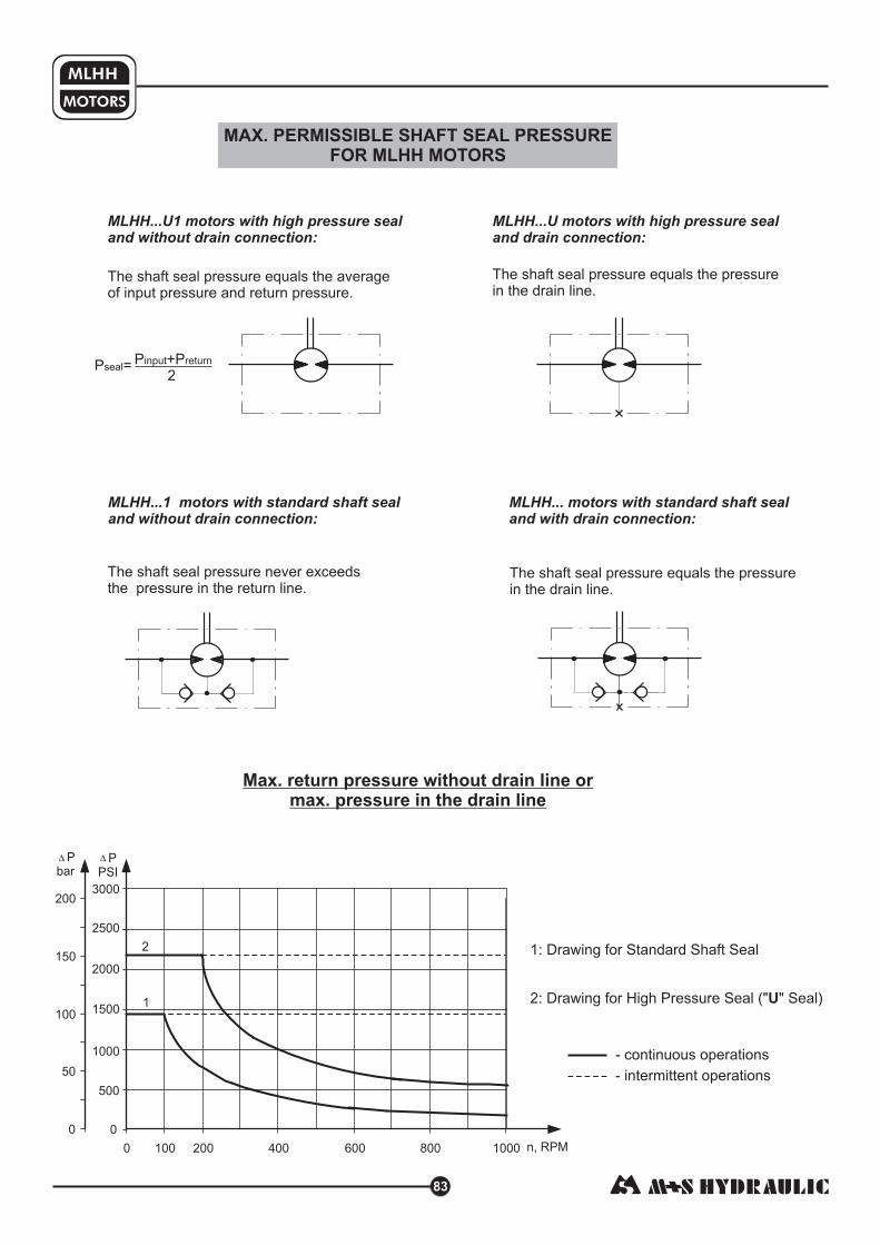
MAX. PERMISSIBLE SHAFT SEAL PRESSUREFOR MLHH MOTORS
1: Drawing for Standard Shaft Seal
2: Drawing for High Pressure Seal (" " Seal)U
MLHH...U1 motors with high pressure sealand without drain connection:
The shaft seal pressure equals the averageof input pressure and return pressure.
MLHH...U motors with high pressure sealand drain connection:
The shaft seal pressure equals the pressurein the drain line.
P = P +Pseal
input return
2
MLHH...1 motors with standard shaft sealand without drain connection:
The shaft seal pressure never exceedsthe pressure in the return line.
The shaft seal pressure equals the pressurein the drain line.
Max. return pressure without drain line ormax. pressure in the drain line
MLHH... motors with standard shaft sealand with drain connection:
83
0
50
100
150
200
0 200 400 600 800 1000 n, RPM100
Pbar
0
500
1000
2000
PPSI
1500
2500
3000
2
1
MLHH
MOTORS
- continuous operations
- intermittent operations

/5 16/5 161¼" [31,75]straight, Parallel key "x "x1¼" BS 46
Max. Torque 6815 [77 daNm]lb-in
K
14T Splined,1¼" [31,75], ANS B 92.1-1976
Max. Torque 8400 [95 daNm]lb-in
L
/5 16/5 161¼" [31,75],SAE J501 Tapered, Parallel key "x "x1"
Max. Torque 8400 [95 daNm]lb-in
R
SHAFT EXTENSIONS
84
K
L
B**
R
M
M L H H
Pos.7
Pos.1
1 2 3 4 5
omit
Pos.2
200
250
315
400
500
- 12.3
- 15.4
- 16.4
- 24.2
- 30.7
in /re
in /r
in /r
in /re
in /re
3
3
3
3
3
2
3
4
5
Pos.3
ORDER CODE
Notes : * The permissible output torque for shafts must not be exceeded!
** The following combination is not allowed: shaft with shaft seal.B U
The hydraulic motors are mangano-phosphatized as standard.
ø35 straight, Parallel key
Max. Torque daNm]
A10x8x45 DIN 6885
8400 lb-in [95
B
Requirement max. Torque must be not exceeded.
M
ø32 straight, Parallel key A10x8x45 DIN 6885Max. Torque 6815 [77 daNm]lb-in
2.224 [56,5]
1.379/1.378 Dia.
[35,018/34,992]
2.283 [58]
.197
[5,0]
2.283 [58]
1.378 [35]
.156/.15
[3,95/3,8]
.313/.312
[7,975/7,95]
2.126 [54]
Pos.6
Pos.4
omit
U
omit
1
Pos.5
6 7
MLHH
MOTORS
1.378/1.366
35/34,7[ ]
1. /1.
[ / ]
391 381
35,33 35,081.250/1.24 Dia.
[31,75/31,7 ]
8
0
3/8-16 UNC
.63 [16] min. deep
1. Dia.
[35]
378
1.889 [48]
.
[
313/.312
7,96/7,94]
1. Dia.
[3 ]
261/1.260
2,018/32,002
M8
.63 [16] min. deep
.394/.392
10/9,96[ ]
1. Dia.
[35]
378
1. Dia.
[35]
378
.394/.392
10/9,96[ ]
1.496/1.495
38,0/37,98[ ]
M8
.63 [16] min. deep
3/8-16 UNC
.63 [16] min. deep
1.
[ ]
3 min
33
1. Dia.
[35]
378
1.889 [48]
1.250/1.249 Dia.
[31,75/31,725]
DP 12/24
Teeth 14
ressure angle 30°P
1.5 Taper per Foot
[cone 1:8]
1.251/1.249 Dia.
[31,775/31,725]
.156 Dia.
[4,0]
1-20 UNEF
Tightening torque for Nut
1680 860 - [20±1 daNm]÷1 lb in
Nut 1-20 UNEF
1 / " [36,5] across flat7 16
1. Dia.
[35]
378
in [mm]
- Displacement code
- 12.3 [201,3 cm /rev]
- 15.4 [252,0 cm /rev]
- 16.4 [314,9 cm /rev]
- 24.2 [396,8 cm /rev]
- 30.7 [502,4 cm /rev]
3
3
3
3
3
in /rev
in /rev
in /rev
in /rev
in /rev
3
3
3
3
3
- Shaft Extensions*
- 1¼" [31,75] straight, Parallel key
- 1¼" [31,75] Splined 14T ANS B92.1-1970
- ø35 straight, Parallel key
- 1¼" [31,75] SAE J501 Tapered
- ø32 straight, Parallel key
- Port Size/Type [standard manifold to each]
- side ports, 2xG1/2, G1/4, BSP thread, ISO 228
- side ports, 2xM22x1,5, M14x1,5, metric thread,ISO 262
- side ports, 2x7/8-14 UNF, O-ring, 7/16-20 UNF
- side ports, 2x1/2-14 NPTF, 7/16-20 UNF
- Shaft Seal Version
-
- High pressure shaft seal (without check valves)
Standard shaft seal
- Drain Port
- with drain port
- without drain port
- Special Features [see page 103]
- Design Series
- Factory specified

HYDRAULIC MOTORS HW
Pressure Losses
85
Max. Displacement,
Max. Speed,
Max. Torque,
Max. Output,
Max. Pressure Drop,
Max. Oil Flow,
Min. Speed,
Pressure fluid
Temperature range,
Optimal Viscosity range,
Filtration
GENERAL
CONTENTS OPTIONS
»
»
»
»
»
Model - Spool valve, roll-gerotor
Wheel and flange mount
Shafts - straight, splined and tapered
SAE and BSPP ports
Other special features
APPLICATION
in /rev [cm /rev]
[RPM]
lb-in [daNm]
HP [kW]
PSI [bar]
GPM [lpm]
[RPM]
F [ C]
SUS [mm /s]
3 3
O O
2
0
2
4
6
8
10
12
14
pbar
00
100
150
200
50
pPSI
90806050403020100
Q, GPM
70
2.5 5 7.5 10 12.5 15 17.5 20 22.5
Q, lpm
16
18250
30020
1450 [100]
2030 [140]
Pressure drop
PSI [bar]
Viscosity
SUS [mm /s]2
Oil flow indrain line
GPM [lpm]
98 [20]
164 [35]
98 [20]
164 [35]
.660 [2,5]
.476 [1,8]
.925 [3,5]
.740 [2,8]
Oil flow in drain line
33.55 [550]
497
cont.: 8500 [96] int.: 9293 [105]
31 [23,1]
cont.: 3000 [205] int.: 3260 [225]
30.4 [115]
10
Mineral based- HLP(DIN 51524) or HM(ISO 6743/4)
-40÷284 [-40÷140]
98÷347 [20÷75]
ISO code 20/16 (Min. recommended fluid filtration of 25 microns)
Specification data .................... 86 87
Function diagrams ................... 88÷94
Dimensions and mounting ...... 95÷99
Permissible shaft Seal Pressure ... 99
Shaft extensions .................. 100÷ 1
Permissible shaft loads .................
Order code ................................... 102
÷
10
100
»
»
»
»
»
»
Conveyors
Feeding mechanism of robots andmanipulators
Metal working machines
Textile machines
Food industries
» Agricultural machines
etc.Grass cutting machinery

Type
Displacement, [ ]
Max. Speed,
[RPM]
Max. Torque
lb-in [daNm]
Max. Output,
HP [kW]
Max. Pressure
Drop, PSI [bar]
Max. Oil Flow
GPM [lpm]
Max. Inlet Pressure,
Max. Starting Pressure
with Unloaded Shaft,
Min. Starting Torque
Min. Speed**, [RPM]
Weight, avg. lb [kg]
in /rev cm /rev
PSI [bar]
PSI [bar]
lb-in [daNm]
3 3
cont.
int.*
cont.
int.*
cont.
int.*
cont.
int.*
cont.
int.*
cont.
int.*
at max. press.drop cont.
at max. press.drop int.*
HW125
HW160
HW200
HW235
HW250
HW300
HW315
7.69 [126]
357
476
3098 [35]
[38,5]
[16,2]
[19,8]
[205]
[225]
12 [45]
16 [60]
[210]
[250]
145 [10]
[28,7]
[31,5]
10
[14,3]
[12,8]
[14,8]
[14,0]
[16,0]
[14,5]
14,7 [ ]
[14,4]
[13,2]
3408
21.7
26.6
2970
3260
3050
3625
2540
2788
31.5
28.2
32.6
30.9
35.3
31.9
30.9 [14,0]
32.4
31.8
29.1
[ ]
380
475
[ ]
[ ]
[ ]
[ ]
[ ]
[ ]
[ ]
[ ]
10
[ ]
9.64
3894
4248
23.6
21,6
2970
3260
3050
3625
3186
3478
32.2
28.9
33.3
31.5
35.9
32.6
31.5 [14,3]
33.1
32.4 [14,7]
29.8 [13,5]
157,8
44
48
17,6
29
[205]
[225]
16 60
20 75
[210]
[250]
145 [10]
36
39,3
14,6
[13,1]
[15,1]
[14,3]
[16,3]
[14,8]
[15,0]
[ ]
[ ]
[ ]
[ ]
[ ]
10
14.33
5710
6196
24.4
30.3
2970 [205]
3260 [225]
20 [75]
26.4 [100]
3050 [210]
3625 [250]
145 [10]
4673
5080
34.2 [15,5]
30.9
35.3
33.5
37.9
34.6 [15,7]
33.5 [15,2]
35.1
34.4 [15,6]
31.8 [14,4]
235,3
319
425
64,5
70
[18,2]
[22,6]
52,8
57,4
[14,0]
[16,0]
[15,2]
[17,2]
[15,9]
[ ]
298
3
[ ]
[ ]
[ ]
[ ]
[ ]
10
[ ]
15.37
6107
6638
22.5
27.9
2970 [205]
3260 [225]
20 [75]
26.4 [100]
3050 [210]
3625 [250]
145 [10]
5000
5443
34.6
31.3
35.7
34.0
38.4
35.1
34.0 [15,4]
35.5 [16,1]
34.8 [15,8]
32.2 [14,6]
252
97
69
75
16,8
[20,8]
56,5
61,5
15,7
[14,2]
[16,2]
[15,4]
[17,4]
[15,9]
[ ]
250
3
[ ]
[ ]
[ ]
[ ]
[ ]
10
[ ]
18.3
7170
7877
16,5
27.9
2970 [205]
3260 [225]
20 [75]
26.4 [100]
3050 [210]
3625 [250]
145 [10]
5877
6452
35.5
32.2
36.6
34.8
39.2
35.9
34.8 [15,8]
36.4
35.7 [16,2]
33.1 [15,0]
300
33
81
89
22
[20,8]
66,4
72,9
16,1
[14,6]
[16,6]
[15,8]
[17,8]
[16,3]
[16,5]
[ ]
238
[ ]
[ ]
[ ]
[ ]
[ ]
10
19.21
7523
8230
21.9
27.9
2970 [205]
3260 [225]
20 [75]
26.4 [100]
3050 [210]
3625 [250]
145 [10]
6169
6744
35.9 [16,3]
32.6
37.0
35.3
39.7
36.4 [16,5]
35.3 [16,0]
36.8
36.2 [16,4]
33.5 [15,2]
314,9
318
85
93
16,4
[20,8]
69,7
76,2
[14,8]
[16,8]
[16,0]
[18,0]
[16,7]
[ ]
4
[ ]
[ ]
[ ]
[ ]
[ ]
[ ]
10
[ ]
12.28
4868
5310
24.9
31
2970 [205]
3260 [225]
26.4
3050
3625
145 [10]
3991
4355
33.3
30.0
34.4
32.6
37.0
33.7
32.6 [14,8]
34.2 [15,5]
33.5 [15,2]
30.86 [14,0]
201,3
373
97
55
60
[18,6]
[23,1]
20 75
100
[210]
[250]
45,1
49,2
15,1
[13,6]
[15,6]
[14,8]
[16,8]
[15,3]
HW
HWF
HWFR
HWS
HWSR
HWD
HWV
HWE
HWSE
HWFE
86
MOTORS
HW
SPECIFICATION DATA
1. Intermittent speed and intermittent pressure drop must not occur simultaneously.
2. Recommended filtration is per ISO cleanliness code 20/16. A nominal filtration of 25 micron or better.
3. Recommend using a premium quality, anti-wear type mineral based hydraulic oil HM (ISO 6743/4).
If using synthetic fluids consult the factory for alternative seal materials.
4. Recommended minimum oil viscosity 13 mm²/s [70 SUS] at 50ºC [122ºF].
5. Recommended maximum system operating temperature is 82ºC [180ºF].
6. To assure optimum motor life fill with fluid prior to loading and run at moderate load and speed for 10-15 minutes.
HLP(DIN51524) or
*
***
**
Intermittent operation: the permissible values may occur for max. 10% of every minute.
For "E"-option it is not recommendable a flow bigger than 75% of the nominal flow rate.
For speeds lower than given, consult factory or your regional manager.

cont.
int.*
cont.
int.*
cont.
int.*
cont.
int.*
cont.
int.*
cont.
int.*
at max. press.drop cont.
at max. press.drop int.*
HW350
HW370
HW400
HW470
HW500
HW535
HW550
21.21
8320
9028
16,5
27.9
2970
3260
20 [75]
26.4 [100]
3050 [210]
3625 [250]
145 [10]
6815
7400
[ ]
[ ]
[ ]
[ ]
[ ]
[ ]
347,8
94
102
22
[20,8]
[205]
[225]
77
83,6
216
2
8
[ ]
88
16,7
[15,2]
[17,2]
[16,4]
[18,4]
[16,8]
[17,1]
36.8
33.5
37.9
36.2
40.6
37.0
36.2 [16,4]
37.7
37.0 [16,8]
34.4 [15,6]
22.51
8497
9293
17.7
25.7
2900 [200]
3200 [220]
20
26.4
3050
3625
7036
7612
[ ]
[ ]
[ ]
[ ]
[ ]
[ ]
369,2
96
105
13,2
[19,2]
[75]
[100]
[210]
[250]
79,5
86
203
2
8
[ ]
71
145 [10]
16,9
[15,4]
[17,4]
[16,6]
[18,6]
37.3
34.0
38.4
36.6
41.0
37.7 [17,1]
36.6 [16,6]
38.1 [17,3]
37.5 [17,0]
34.8 [15,8]
28.71
8143
8939
14.2
23.3
2180
2390
20 [75]
30.4
3050 [210]
3625 [250]
145 [10]
6674
7328
[ ]
[ ]
[ ]
[ ]
[ ]
[ ]
[ ]
[ ]
[ ]
470,6
92
101
10,6
[17,4]
150
165
115
75,4
82,8
159
8
244
[17,8]
[19,8]
[18,3]
39.9 [18,1]
36.6 [16,6]
41.0 [18,6]
39.2
43.7
40.3
39.2 [17,8]
40.8 [18,5]
40.1 [18,2]
37.5 [17,0]
30.65
8054
8939
14.5
23.9
2030
2250
20 [75]
30.4 [115]
3050 [210]
3625 [250]
145 [10]
6603
7328 [82,8]
[ ]
[ ]
[ ]
[ ]
[ ]
[ ]
[ ]
502,4
91
101
10,8
[17,8]
140
155
74,6
149
8
229
[18,9]
[18,1]
[20,1]
40.6 [18,4]
37.3 [16,9]
41.7
39.9
44.3
41.0 [18,6]
39.9 [18,1]
41.7 [18,9]
40.8 [18,5]
38.1 [17,3]
32.7
7966
9205
12.6
16,4
1885
2180
20 [75]
30.4 [115]
3050 [210]
3625 [250]
145 [10]
6532
7540
[ ]
[ ]
[ ]
[ ]
[ ]
[ ]
[ ]
[ ]
535
90
104
9,4
22 [ ]
130
150
73,8
85,2
140
5
[ ]
215
8 18,8
[19,3]
[18,5]
[20,5]
[19,2]
41.5
38.1 [17,3]
42.5
40.8
45.2
41.9 [19,0]
40.8 [18,5]
42.3
41.7 [18,9]
39.0 [17,7]
[ ]
136
[ ]
[ ]
[ ]
[ ]
[ ]
[ ]
[ ]
5
33.55
7877
9293
21.2
1815
2105
20 [75]
30.4 [115]
3050 [210]
3625 [250]
145 [10]
6452
7470
41.7 [18,9]
38.4 [17,4]
42.8
41.0
45.4
42.1
41.0 [18,6]
42.5 [19,3]
41.9 [19,0]
39.2 [17,8]
550
209
89
105
12 9
[15,8]
125
145
72,9
84,4
[19,4]
[18,6]
[20,6]
[19,1]
24.2
8497
8674
16.8
24.8
2680
2760
20 [75]
26.4 [100]
3050 [210]
3625 [250]
145 [10]
6966
7107
[ ]
[ ]
[
[ ]
[ ]
[ ]
[ ]
[ ]
396,8
96
98]
12,5
[18,5]
185
190
78,7
80,3
189
2
8
52
[17,8]
[17,0]
[19,0]
[17,5]
[17,7]
38.1 [17,3]
34.8 [15,8]
39.2
37.5
41.9
38.6
37.5 [17,0]
39.0
38.4 [17,4]
35.7 [16,2]
Type
Displacement, cm /rev [in /rev]
Max. Speed,
[RPM]
Max. Torque
daNm [in-lb]
Max. Output,
kW [HP]
Max. Pressure
Drop, bar [PSI]
Max. Oil Flow
lpm [GPM]
Max. Inlet Pressure,
bar [PSI]
Max. Starting Pressure
with Unloaded Shaft, bar [PSI]
Min. Starting Torque
daNm [in-lb]
Min. Speed**, [RPM]
Weight, avg. kg [lb]
3 3
HW
HWF
HWFR
HWS
HWSR
HWD
HWV
HWE
HWSE
HWFE
87
MOTORS
HW
SPECIFICATION DATA
1. Intermittent speed and intermittent pressure drop must not occur simultaneously.
2. Recommended filtration is per ISO cleanliness code 20/16. A nominal filtration of 25 micron or better.
3. Recommend using a premium quality, anti-wear type mineral based hydraulic oil HM (ISO 6743/4).
If using synthetic fluids consult the factory for alternative seal materials.
4. Recommended minimum oil viscosity 13 mm²/s [70 SUS] at 50ºC [122ºF].
5. Recommended maximum system operating temperature is 82ºC [180ºF].
6. To assure optimum motor life fill with fluid prior to loading and run at moderate load and speed for 10-15 minutes.
HLP(DIN51524) or
*
***
**
Intermittent operation: the permissible values may occur for max. 10% of every minute.
For "E"-option it is not recommendable a flow bigger than 75% of the nominal flow rate.
For speeds lower than given, consult factory or your regional manager.

MOTORS
HW
88
The function diagrams data is for average performance of randomly selected motors at back pressure[ ] and oil with viscosity of [ ] at [ ].72.5÷145 PSI 5÷10 bar 150 SUS 32 mm²/s 122 F 50°C
o
HW 125
HW 160
FUNCTION DIAGRAMS
cont. int.
RPM
n
0 200100 300250150 35050 400 450 500
cont.
int.35
MdaNm
0
5
10
15
20
25
Mlb-in
30
40
0
1000
1500
2000
2500
3000
500
3500
20 l/m
in5.3
GP
M
30 l/m
in7.9
GP
M
40 l/m
in10.6
GP
M
10 l/m
in2.6
GP
M
50 l/m
in13.2
GP
M
60 l/m
in16 G
PM
Q=
5 l/m
in1.3
GP
M
45 l/m
in11.9
GP
M
15 l/m
in3.9
GP
M
205 bar2970 PSI
70 bar1020 PSI
35 bar510 PSI
100 bar1450 PSI
140 bar2030 PSI
120 bar1740 PSI
175 bar2540 PSI
p=225 bar3260 PSI
N=1.5 kW
t=80%
75%65%
70%
3 kW
60%55%
5 kW
7 kW
10 kW
cont. int.
RPM
n
0 200100 300250150 35050 400 450 500
cont.
int.
35
MdaNm
0
5
10
15
20
25
Mlb-in
30
50
0
1000
1500
2000
2500
3000
500
3500 40
454000
4500
205 bar2970 PSI
70 bar1020 PSI
35 bar510 PSI
100 bar1450 PSI
140 bar2030 PSI
120 bar1740 PSI
175 bar2540 PSI
p=225 bar3260 PSI
20 l/m
in5.3
GP
M
30 l/m
in7.9
GP
M
40 l/m
in10.6
GP
M
10 l/m
in2.6
GP
M
50 l/m
in13.2
GP
M
60 l/m
in16 G
PM
15 l/m
in3.9
GP
M
75 l/m
in20 G
PM
t=85%
80%
75%
70%65%
N=2 kW 4 kW
6 kW
8 kW
11 kW
Q=
5 l/m
in1.3
GP
M

MOTORS
HW
89
HW 200
HW 235
FUNCTION DIAGRAMS
cont. int.
RPM
n
0 12060 30015090 33030 360 450
cont. int.
RPM
n
0 200100 300250150 35050 400 450 500
0
8
16
24
32
40
48
56
64
0
1000
1500
2000
2500
3000
500
3500
4000
4500
5000
5500
MdaNm
Mlb-in
cont.
int.
205 bar2970 PSI
70 bar1020 PSI
35 bar510 PSI
100 bar1450 PSI
160 bar2320 PSI
120 bar1740 PSI
175 bar2540 PSI
p=225 bar3260 PSI
20 l/m
in5.3
GP
M
30 l/m
in7.9
GP
M
40 l/m
in10.6
GP
M
10 l/m
in2.6
GP
M
50 l/m
in13.2
GP
M
60 l/m
in16 G
PM
15 l/m
in3.9
GP
M
75 l/m
in20 G
PM
100 l/m
in26.4
GP
M
Q=
5 l/m
in1.3
GP
M
t=83% 80%
70%75%
65%
2 kW
6 kW
8 kW
10 kW
14 kW
12 kW
4 kW
0
8
16
24
32
40
48
56
72
64
0
1000
1500
2000
2500
3000
500
3500
4000
4500
5000
5500
6000
6500
MdaNm
Mlb-in
cont.
int.
205 bar2970 PSI
70 bar1020 PSI
35 bar510 PSI
100 bar1450 PSI
160 bar2320 PSI
120 bar1740 PSI
175 bar2540 PSI
p=225 bar3260 PSI
180 210 240 270 390 420
20 l/m
in5.3
GP
M
30 l/m
in7.9
GP
M
40 l/m
in10.6
GP
M
10 l/m
in2.6
GP
M
50 l/m
in13.2
GP
M
60 l/m
in16 G
PM
15 l/m
in3.9
GP
M
75 l/m
in20 G
PM
Q=
5 l/m
in1.3
GP
M
100 l/m
in26.4
GP
M
N=1,5 kW
3 kW
5 kW
7 kW
9 kW 11 kW
13 kW
15 kW
70%
65%60%t=75%
N=2 kW
The function diagrams data is for average performance of randomly selected motors at back pressure[ ] and oil with viscosity of [ ] at [ ].72.5÷145 PSI 5÷10 bar 150 SUS 32 mm²/s 122 F 50°C
o

MOTORS
HW
90
HW 250
HW 300
FUNCTION DIAGRAMS
cont. int.
RPM
n
0 200100 300250150 35050 400
MdaNm
0
10
20
30
40
50
0
1000
2000
3000
Mlb-in
4000
60
70
5000
6000
7000 80
cont. int.
RPM
n
0 200100 300250150 35050
MdaNm
0
10
20
30
40
50
0
1000
2000
3000
Mlb-in
4000
60
70
5000
6000
7000 80
908000
9000100
cont.
int.
20 l/m
in5.3
GP
M
30 l/m
in7.9
GP
M
40 l/m
in10.6
GP
M
10 l/m
in2.6
GP
M
50 l/m
in13.2
GP
M
60 l/m
in16 G
PM
15 l/m
in3.9
GP
M
75 l/m
in20 G
PM
Q=
5 l/m
in1.3
GP
M
100 l/m
in26.4
GP
M
205 bar2970 PSI
160 bar1320 PSI
70 bar1020 PSI
35 bar510 PSI
100 bar1450 PSI
120 bar1740 PSI
175 bar2540 PSI
p=225 bar3260 PSI
t=80%
75%
70%
65%N=1 kW
2 kW
4 kW 6 kW8 kW 10 kW
12 kW14 kW
205 bar2970 PSI
160 bar1320 PSI
70 bar1020 PSI
35 bar510 PSI
100 bar1450 PSI
120 bar1740 PSI
175 bar2540 PSI
p=225 bar3260 PSI
t=80%
65%
3 kW
5 kW
7 kW
10 kW
13 kW 16 kW
70%75%
N=1 kW
20 l/m
in5.3
GP
M
30 l/m
in7.9
GP
M
40 l/m
in10.6
GP
M
50 l/m
in13.2
GP
M
60 l/m
in16 G
PM
15 l/m
in3.9
GP
M
75 l/m
in20 G
PM
Q=
5 l/m
in1.3
GP
M
100 l/m
in26.4
GP
M
cont.
int.
10 l/m
in2.6
GP
M
The function diagrams data is for average performance of randomly selected motors at back pressure[ ] and oil with viscosity of [ ] at [ ].72.5÷145 PSI 5÷10 bar 150 SUS 32 mm²/s 122 F 50°C
o

MOTORS
HW
91
HW 315
HW 350
FUNCTION DIAGRAMS
RPM0 200100 2251505025 75 125 175 250 300275 325
ncont. int.
MdaNm
0
10
20
30
40
50
0
1000
2000
3000
Mlb-in
4000
60
70
5000
6000
7000 80
908000
cont.
int.
205 bar2970 PSI
160 bar1320 PSI
70 bar1020 PSI
35 bar510 PSI
100 bar1450 PSI
120 bar1740 PSI
175 bar2540 PSI
p=225 bar3260 PSI
20 l/m
in5.3
GP
M
30 l/m
in7.9
GP
M
40 l/m
in10.6
GP
M
50 l/m
in13.2
GP
M
60 l/m
in16 G
PM
15 l/m
in3.9
GP
M
75 l/m
in20 G
PM
Q=
5 l/m
in1.3
GP
M
100 l/m
in26.4
GP
M
10 l/m
in2.6
GP
M
t=80%
75% 70%
65% N=1 kW
5 kW7 kW
9 kW 11 kW 13 kW
15 kW
3 kW
RPM0 200100 2251505025 75 125 175 250 300275
ncont. int.
205 bar2970 PSI
160 bar1320 PSI
70 bar1020 PSI
35 bar510 PSI
100 bar1450 PSI
120 bar1740 PSI
175 bar2540 PSI
p=225 bar3260 PSI
20 l/m
in5.3
GP
M
30 l/m
in7.9
GP
M
40 l/m
in10.6
GP
M
50 l/m
in13.2
GP
M
60 l/m
in16 G
PM
15 l/m
in3.9
GP
M
75 l/m
in20 G
PM
Q=
5 l/m
in1.3
GP
M
100 l/m
in26.4
GP
M
10 l/m
in2.6
GP
M
60
0
12
24
36
48
72
84
MdaNm
Mlb-in
cont.
int.96
108
0
1000
2000
3000
4000
5000
6000
7000
8000
9000
t=78%75%
70%65%
60%
N=1 kW
2 kW
4 kW
6 kW
8 kW
10 kW
12 kW 14 kW
The function diagrams data is for average performance of randomly selected motors at back pressure[ ] and oil with viscosity of [ ] at [ ].72.5÷145 PSI 5÷10 bar 150 SUS 32 mm²/s 122 F 50°C
o

92
MOTORS
HW
HW 370
HW 400
FUNCTION DIAGRAMS
RPM0 200100 2251505025 75 125 175 250 300275
ncont. int.
RPM0 200100 2251505025 75 125 175 250 275
ncont. int.
205 bar2970 PSI
160 bar1320 PSI
70 bar1020 PSI
35 bar510 PSI
100 bar1450 PSI
120 bar1740 PSI
175 bar2540 PSI
p=225 bar3260 PSI
cont.
int.
20 l/m
in5.3
GP
M
30 l/m
in7.9
GP
M
40 l/m
in10.6
GP
M
50 l/m
in13.2
GP
M
60 l/m
in16 G
PM
15 l/m
in3.9
GP
M
75 l/m
in20 G
PM
Q=
5 l/m
in1.3
GP
M
100 l/m
in26.4
GP
M
10 l/m
in2.6
GP
M
15 kW
MdaNm
0
1000
2000
3000
Mlb-in
4000
5000
6000
7000
8000
75
0
15
60
105
30
120
90
45
9000
10000
t=80%
75% 70%65% 60%
N=1 kW
3 kW
5 kW
7 kW 9 kW
11 kW
13 kW
n
160 bar1320 PSI
70 bar1020 PSI
35 bar510 PSI
90 bar1305 PSI
120 bar1740 PSI
185 bar2680 PSI
p=190 bar2760 PSI
cont.
int.
20 l/m
in5.3
GP
M
30 l/m
in7.9
GP
M
40 l/m
in10.6
GP
M
50 l/m
in13.2
GP
M
60 l/m
in16 G
PM
15 l/m
in3.9
GP
M
75 l/m
in20 G
PM
100 l/m
in26.4
GP
M
10 l/m
in2.6
GP
M
MdaNm
0
1000
2000
3000
Mlb-in
4000
5000
6000
7000
8000
75
0
15
60
105
30
120
90
45
9000
10000
t=80%
75% 70%
65% 60%
3 kW
5 kW
7 kW
9 kW11 kW 13 kW
N=1,5 kW
The function diagrams data is for average performance of randomly selected motors at back pressure[ ] and oil with viscosity of [ ] at [ ].72.5÷145 PSI 5÷10 bar 150 SUS 32 mm²/s 122 F 50°C
o

MOTORS
HW
93
RPM0 200100 2251505025 75 125 175 250
ncont. int.
70 bar1020 PSI
35 bar510 PSI
120 bar1740 PSI
150 bar2180 PSI
p=165 bar2390 PSI
cont.
int.
20 l/m
in5.3
GP
M
30 l/m
in7.9
GP
M
40 l/m
in10.6
GP
M
50 l/m
in13.2
GP
M
60 l/m
in16 G
PM
15 l/m
in3.9
GP
M
75 l/m
in20 G
PM
Q=
5 l/m
in1.3
GP
M
115 l/m
in30.4
GP
M
10 l/m
in2.6
GP
MM
daNm
0
1000
2000
3000
Mlb-in
4000
5000
6000
7000
8000
75
0
15
60
105
30
120
90
45
9000
10000
t=80%75%
70%
65%
60% N=0,8 kW
3 kW
5 kW
7 kW 9 kW
11 kW
HW 470
HW 500
FUNCTION DIAGRAMS
1,5 kW
90 bar1305 PSI
RPM0 200100 2251505025 75 125 175 250
ncont. int.
70 bar1020 PSI
35 bar510 PSI
120 bar1740 PSI
150 bar2180 PSI
p=165 bar2390 PSI
cont.
int.
20 l/m
in5.3
GP
M
30 l/m
in7.9
GP
M
40 l/m
in10.6
GP
M
50 l/m
in13.2
GP
M
60 l/m
in16 G
PM
15 l/m
in3.9
GP
M
75 l/m
in20 G
PM
Q=
5 l/m
in1.3
GP
M
11
5 l/m
in3
0.4
GP
M
10 l/m
in2.6
GP
M
MdaNm
0
1000
2000
3000
Mlb-in
4000
5000
6000
7000
8000
75
0
15
60
105
30
120
90
45
9000
10000
t=78% 75%
70%
65%60%N=1 kW
7 kW
9 kW
11 kW
90 bar1305 PSI
135
11000
12000
13 kW
3 kW
5 kW
The function diagrams data is for average performance of randomly selected motors at back pressure[ ] and oil with viscosity of [ ] at [ ].72.5÷145 PSI 5÷10 bar 150 SUS 32 mm²/s 122 F 50°C
o

MOTORS
HW
94
HW 535
HW 550
FUNCTION DIAGRAMS
RPM0 20080 2201204020 60 100 140
ncont. int.
70 bar1020 PSI
35 bar510 PSI
120 bar1740 PSI
130 bar1885 PSI
p=150 bar2180 PSI
cont.
int.
20 l/m
in5.3
GP
M
30 l/m
in7.9
GP
M
40 l/m
in10.6
GP
M
50 l/m
in13.2
GP
M
60 l/m
in16 G
PM
15 l/m
in3.9
GP
M
75 l/m
in20 G
PM
Q=
5 l/m
in1.3
GP
M
115 l/m
in30.4
GP
M
10 l/m
in2.6
GP
M
MdaNm
0
1000
2000
3000
Mlb-in
4000
5000
6000
7000
8000
75
0
15
60
105
30
120
90
45
9000
10000
t=80%
75%
70% 65%
60% N=1 kW
3 kW
5 kW 7 kW9 kW 11 kW
2 kW
80 bar1160 PSI
RPM
ncont. int.
70 bar1020 PSI
35 bar510 PSI
125 bar1815 PSI
p=145 bar2105 PSI
cont.
int.
20 l/m
in5.3
GP
M
30 l/m
in7.9
GP
M
40 l/m
in10.6
GP
M
50 l/m
in13.2
GP
M
60 l/m
in16 G
PM
15 l/m
in3.9
GP
M
75 l/m
in20 G
PM
Q=
5 l/m
in1.3
GP
M
11
5 l/m
in3
0.4
GP
M
10 l/m
in2.6
GP
M
MdaNm
Mlb-in
75
0
15
60
105
30
120
90
45
75%70%
65%
N=1 kW
3 kW
5 kW
7 kW
9 kW
11 kW
160 180
17 bar250 PSI
0 20080 1204020 60 100 140 160 180
0
1000
2000
3000
4000
5000
6000
7000
8000
9000
10000
17 bar250 PSI
80 bar1160 PSI
100 bar1450 PSI
2 kW
t=80%
The function diagrams data is for average performance of randomly selected motors at back pressure[ ] and oil with viscosity of [ ] at [ ].72.5÷145 PSI 5÷10 bar 150 SUS 32 mm²/s 122 F 50°C
o

95
in [mm]
Standard RotationViewed from Shaft EndPort Pressurized -Port Pressurized -
A CWB CCW
Reverse RotationViewed from Shaft EndPort Pressurized -Port Pressurized -
A CCWB CW
- Motor Mounting Surface
5.51 [140,5]
5.71 [145,0]
5.95 [151,0]
6.12 [155,5]
6.22 [158,0]
6.48 [164,5]
6.56 [166,5]
6.73 [171,0]
6.85 [174,0]
7.01 [178,0]
7.40 [188,0]
7.58 [192,5]
7.76 [197,0]
7.84 [199,0]
DIMENSIONS AND MOUNTING DATADIMENSIONS AND MOUNTING DATA
* LSV LFor option the dimension is
.118 in [3 mm] greater.
HW 125
HW 160
HW 200
HW 235
HW 250
HW 300
HW 315
HW 350
HW 370
HW 400
HW 470
HW 500
HW 535
HW 550
(S)
(S)
(S)
(S)
(S)
(S)
(S)
(S)
(S)
(S)
(S)
(S)
(S)
(S)
Type *L, in [mm] L , in [mm]1
.68 [17,4]
.86 [21,8]
1.09 [27,8]
1.28 [32,5]
1.37 [34,8]
1.63 [41,4]
1.71 [43,5]
1.89 [48,0]
2.01 [51,0]
2.16 [54,8]
2.56 [65,0]
2.73 [69,4]
2.92 [74,1]
2.99 [76,0]P
T
(A,B)
Versions
4
2x -14UNF,O-ring-20UNF,O-ring
78/
716/
2
2xG½
G ¼
MOTORS
HW
Note: For N see page 100 101.N and s ÷S
5.275 [134]
[147,8/147,4]
5.819/5.803 Dia. 2.52 min
[64]
5.275[134]
HW - Wheel Mount
max L
.252/.244
max N
[127]
4.92 Dia.[125]
5.0 Dia.3.236 Dia.
[82,2]
L1[6,4/6,2]
[51,55/51,25]
2.03/2.18
[25,8/25,4]
1.016/1.0
[46,2/45,8]
1.819/1.803
[9,4/8,9].37/.35
[23,2/22,8].913/.898
T
4x.539/.53[13,7/13,5]Dia. Thru
3.25/3.248[82,55/82,5]
Pilot Dia.
[23,2/22,8].913/.898
Port B
Port A
P(A,B)
5.275 [134]
5.275[134]
2.52 min
[64][147,8/147,4]
5.819/5.803 Dia.P(A,B)
max Lmax NS
T
[7,1/6,6]
.279/.26
[25,55/25,25]
1.006/.994
.756/.748
[19,2/19]
[37,3/36,8]
1.468/1.449
[4,6/4,1]
.181/.161
[127]
4.92 Dia.[125]
5.0 Dia.
L1
4x.539/.53[13,7/13,5]Dia. Thru
3.236 Dia.[82,2]
3.25/3.248[82,55/82,5]
Pilot Dia.
[4 ,9/4 ,5]6 6
1.8 6/1.84 31
[25,55/25,25]
1.006/.994
Port B
Port A
HWS - Wheel Mount

96
DIMENSIONS AND MOUNTING DATADIMENSIONS AND MOUNTING DATA
HW 125
HW 160
HW 200
HW 235
HW 250
HW 300
HW 315
HW 350
HW 370
HW 400
HW 470
HW 500
HW 535
HW 550
...
...
...
...
...
...
...
...
...
...
...
...
...
...
Type
5.73 [ 45, ]
5.91 [150 ]
6.14 [ 56 ]
6.32 [160, ]
6.42 [ 63 ]
6.67 [ 69 ]
6.75 [ 71 ]
6.93 [ 76 ]
7.05 [ 79 ]
7.20 [ 83 ]
7.60 [193 ]
7.78 [197 ]
7.95 [ 02 ]
8.03 [ 04 ]
1 5
,0
1 ,0
5
1 ,0
1 ,5
1 ,5
1 ,0
1 ,0
1 ,0
,0
,5
2 ,0
2 ,0
HWE, HWSE
.68 [17,4]
.86 [21,8]
1.09 [27,8]
1.28 [32,5]
1.37 [34,8]
1.63 [41,4]
1.71 [43,5]
1.89 [48,0]
2.01 [51,0]
2.16 [54,8]
2.56 [65,0]
2.73 [69,4]
2.92 [74,1]
2.99 [76,0]
*L, in [mm]
7.44 [189, ]
7.62 [193 ]
7.85 [199 ]
8.03 [204, ]
8.13 [ 06 ]
8.39 [ 13 ]
8.46 [ 15 ]
8.64 [ 19 ]
8.76 [ 22 ]
8.92 [ 26 ]
9.31 [ 36 ]
9.49 [ 41 ]
9.67 [ 45 5]
9.74 [ 47 ]
0
,5
,5
0
2 ,5
2 ,0
2 ,0
2 ,5
2 ,5
2 ,5
2 ,5
2 ,0
2 ,
2 ,5
HWFEL , in [mm]1
* LSV LFor option the dimension is .118 in [3 mm] greater.
Standard RotationViewed from Shaft EndPort Pressurized -Port Pressurized -
A CWB CCW
Reverse RotationViewed from Shaft EndPort Pressurized -Port Pressurized -
A CCWB CW
mm [in]
P(A,B)
Versions
6
2x -18 UNF,O-ring-20 UNF,O-ring
916/
716/
G ¼
5
38/2xG
T
HWSE - Wheel Mount, rear ports
HW(S)EHWE - Wheel Mount, rear ports
HWFE - Magneto Mount
max L
L1
P(A,B).19
[ ]5
1.24
[31,5]
min 2.5 [64]
5.275[134]min
5.275 [134] min
.6
[15,2]
.6
[15,2]
[147,8/147,4]
5.819/5.803 Dia.
4x.539/.53[13,7/13,5]Dia. Thru
TL1
max Lmax N
4.92[125]Dia.
5.0[127]Dia.
3.236 Dia.[82,2]
3.25/3.248[82,55/82,5]
Pilot Dia.
[9,4/8,9].37/.35
.252/.244[6,4/6,2]
.913/.898[23,2/22,8]
.913/.898[23,2/22,8]
[25,8/25,4]
1.016/1.0
[51,55/51,25]
2.03/2.18
[46,2/45,8]
1.819/1.803
Port A
Port B
5.0[127]Dia.
4.92[125]Dia.
4x.539/.53[13,7/13,5]Dia. Thru
1.468/1.449
[37,3/36,8]
.756/.748
[19,2/19]
3.236 Dia.[82,2]
3.25/3.248[82,55/82,5]
Pilot Dia.
max NS
.181/.161[4,6/4,1]
[25,55/25,25]
1.006/.994
[25,55/25,25]
1.006/.994
.279/.26
[7,1/6,6]
1.8 6/1.8
[4 ,9/4 ,5]
4 31
6 6
5.275[134]min
T
P(A,B)
.19
[ ]5
1.24
[31,5]
Port B
Port A
.6
[15,2]
.6
[15,2]
- Motor Mounting Surface
Note: For N see page 100 101.N and s ÷S
MOTORS
HW

DIMENSIONS AND MOUNTING DATADIMENSIONS AND MOUNTING DATA
Standard RotationViewed from Shaft EndPort Pressurized -Port Pressurized -
A CWB CCW
Reverse RotationViewed from Shaft EndPort Pressurized -Port Pressurized -
A CCWB CW
HWSR - Wheel mount, relief valves
HWFR - Wheel mount, six holes, relief valves
HW 125
HW 160
HW 200
HW 235
HW 250
HW 300
HW 315
HW 350
HW 370
HW 400
HW 470
HW 500
HW 535
HW 550
...
...
...
...
...
...
...
...
...
...
...
...
...
...
Type
6.24 158 5[ , ]
[1 ]
[ ]
[1 , ]
[ ]
[ ]
[ ]
[ ]
[ ]
[ ]
[ ]
[ ]
[ ]
[ ]
6.42 63,0
6.65 169,0
6.83 73 5
6.93 176,0
7.19 182,5
7.26 184,5
7.44 189,0
7.56 192,0
7.72 196,0
8.11 206,0
8.29 210,5
8.46 215,0
8.54 217,0
HWSR
.68 [17,4]
.86 [21,8]
1.09 [27,8]
1.28 [32,5]
1.37 [34,8]
1.63 [41,4]
1.71 [43,5]
1.89 [48,0]
2.01 [51,0]
2.16 [54,8]
2.56 [65,0]
2.73 [69,4]
2.92 [74,1]
2.99 [76,0]
L ,in [mm]*max
7.95 202 0[ , ]
[ ]
[ ]
[ , ]
[ ]
[ ]
[ ]
[ ]
[ ]
[ ]
[ ]
[ ]
[ ]
[ ]
8.13 206,5
8.37 212,5
8.54 217 0
8.64 219,5
8.89 226,0
8.98 228,0
9.15 232,5
9.27 235,5
9.43 239,5
9.82 249,5
10.00 254,0
10.19 258,8
10.26 260,5
HWFR
L1
in [mm]
* LSV LFor option the dimension is .118 in [3 mm] greater.
P(A,B)
Versions
4
2x -14UNF,O-ring
78/
2
2xG½
- Motor Mounting Surface
Note: For N see page 100 101.FR SRand N s ÷
in [mm]
5.276[134]
5.4[137]
5.276 [134]
25 30'o
1.84/1.83
[46,9/46,5]
s=5
.76/.74
[19,2/19]
.18/.16
[4,6/4,1]
.28/.26
[7,1/6,6]
3.25/3.248 Dia.
[82,55/82,5]
1.47/1.45
[37,3/36,8]
max L
.67
[17]L1
s=22
4.921 Dia.[125]
.91
[23]
1.71 [43,5]
1.57
[40]
max NSR
B A
5.276 [134]
1.006/.994[25,55/25,25]
5.819/5.803 Dia.
[147,8/147,4]
5.276[134]
4x .539/.53[13,7/13,5]Dia. thru
1.006/.994[25,55/25,25]
B A
22 30'o
6x .524/.516[13,3/13,1]Dia. thru
22 30'o
.913/.89
[23,2/22,8]
.913/.89
[23,2/22,8]
3.465 [88]
4.189 Dia.
[106,4]
2.598[66]max
3.25/3.248 Dia.
[82,55/82,5]
max L
L1
s=22
s=5
.67[17]
.91
[23]
4.921 Dia.[125]
1.71 [43,5]
1.57
[40]
.118/.11
[3/2,8]
2.71/2.69
[68,9/68,5]
max NFR
max 5.4 [137]
5.4[137]
25 30'o
97
1 - 1015 PSI [ bar]
2 - 1450 PSI [100 bar]
70 3 - 2030 PSI [140 bar]
4 - 2470 PSI [170 bar]
5 - 3050 PSI [210 bar]
Q GPM,0 2.5 5 7.5 10 12.5 15 17.5 20
Q lpm,
4000
3000
2000
1000
5
Pbar
PPSI
10 20 30 40 50 60 70000
50
100
150
200
250
80
5
4
3
2
1
Pressure Settings at Flow
Q=1.32 GPM [5 lpm] 150 SUS [ mm /s], 122 F [50 C], 322 o o
MOTORS
HW

DIMENSIONS AND MOUNTING DATADIMENSIONS AND MOUNTING DATA
* LSVFor option the dimension
L is .118 in [3 mm] greater.P
T
(A,B)
Versions
4
2x -14UNF,O-ring-20UNF,O-ring
78/
716/
2
2xG½
G ¼
- Motor Mounting Surface
Standard RotationViewed from Shaft EndPort Pressurized -Port Pressurized -
A CWB CCW
Reverse RotationViewed from Shaft EndPort Pressurized -Port Pressurized -
A CCWB CW
T
Versions
4
-20UNF,O-ring
716/
2
G ¼
Note: For N see page 100 101.D Vand N s ÷
HWD MountWheel
HWV MountWheel
2.52 [ ]64 min
5.276[134]
5.276[134]
5.819/5.803 Dia.[147,8/147,4]
L1
T
max ND
1.49/1.5
[37,8/38,2]
P(A, B)
.70/.71
[17,9/18,1]
Port A
Port B
4.921 Dia.[125]4.99/5.0 Dia.
[126,96/127]
.118/.138[3/3,5]
4x .54/.53 Dia. Thru[13,7/13,5]
3.5/3.49 Dia.[88,8/88,7]
.89/.91[22,85/23,15]
.89/.91[22,85/23,15]
1.73/1.74
[44,1/44,3]
134 [5.276]
5.276[134]
5.819/5.803 Dia.[147,8/147,4]
max NV
L1 1.45/1.47
[ /37,3]36,8
max L
4xM6min .51 [13]
O-ring .53x.103
[13,37x2,62]
4.921 Dia.[125]
4.99/5.0 Dia.[126,96/127]
.26/.28
[6,6/7,1]
4x .54/.53 Dia. Thru[13,7/13,5]
.73/.72
[18,6/18,4]
.19/.20
[5,0/5,2]
1.83/1.8546,5/46,9[ ]
1.05/1.0426,7/26,5[ ]
.18 .16//[ ]4,6 4,1
.90/.85[22,95/22,75]
1.81/1.79[45,85/45,55]
1.25/1.24[31,85/31,65]
2.51/2.49[63,65/63,35]
3 24. Dia.
[ ]82,2
3 2. 5/3.248 Dia.
[ ]82,55/82,5
HW 125
HW 160
HW 200
HW 235
HW 250
HW 300
HW 315
HW 350
HW 370
HW 400
HW 470
HW 500
HW 535
HW 550
...
...
...
...
...
...
...
...
...
...
...
...
...
...
TypeHWD
*L, in [mm]
HWVL , in [mm]1
5.59 42 0
5.79 [147,0]
6.02 [153,0]
6.22 [158,0]
6.30 [160,0]
[1 , ]
6.56 [166,5]
6.65 [169,0]
6.83 [173,5]
6.95 [176,5]
7.09 [180,0]
7.50 [190,5]
7.66 [194,5]
7.85 [199,5]
7.93 [201,5]
5.53 40 5[1 , ]
[1 5 ]
[ ]
[1 , ]
[ ]
[ ]
[ ]
[ ]
[ ]
[ ]
[ ]
[ ]
[ ]
[ ]
5.71 4 ,0
5.94 151,0
6.12 55 5
6.22 158,0
6.46 164,5
6.56 166,5
6.73 171,0
6.85 174,0
7.01 178,0
7.40 188,0
7.58 192,5
7.76 197,0
7.83 199,0
.68 [17,4]
.86 [21,8]
1.09 [27,8]
1.28 [32,5]
1.37 [34,8]
1.63 [41,4]
1.71 [43,5]
1.89 [48,0]
2.01 [51,0]
2.16 [54,8]
2.56 [65,0]
2.73 [69,4]
2.92 [74,1]
2.99 [76,0]
in [mm]
98
MOTORS
HW
max L

DIMENSIONS AND MOUNTING DATADIMENSIONS AND MOUNTING DATA
* LSV LFor option the dimension is
.118 in [3 mm] greater.
Standard Rotation
Viewed from Shaft EndPort Pressurized -A CW
Port Pressurized -B CCW
Reverse Rotation
Viewed from Shaft EndPort Pressurized -A CCW
Port Pressurized -B CW
- Motor Mounting Surface
Note: For N see page 100 101.F s ÷
[3,2/3]
.126/.118[2,05/2]
.098/.079
M 5:1
MAX. PERMISSIBLE SHAFT SEAL PRESSURE
The shaft seal pressure equals the pressure in the drain line.
HW, HWF, HWS,
HWD, HWV
HWFR, HWSR
in [mm]
99
HW... motors with drain connection:
00 70
500
1000
1500
2000
2500
P
bar
P
PSI
50
100
150
200
0100 200 300 400 500 600 n, RPM140
1
2
- continuous operations
- intermittent operations1 - standard version2 - shaft “C” version
MOTORS
HW
HWF 125
HWF 160
HWF 200
HWF 235
HWF 250
HWF 300
HWF 315
HWF 350
HWF 370
HWF 400
HWF 470
HWF 500
HWF 535
HWF 550
7.24 [184,0]
7.42 [188,5]
7.66 [194,5]
7.84 [199,0]
7.93 [201,5]
8.20 [208,0]
8.27 [210,0]
8.45 [214,5]
8.56 [217,5]
8.72 [221,5]
9.11 [231,5]
9.29 [236,0]
9.47 [240,5]
9.55 [242,5]
Type *L, in [mm] L , in [mm]1
.68 [17,4]
.86 [21,8]
1.09 [27,8]
1.28 [32,5]
1.37 [34,8]
1.63 [41,4]
1.71 [43,5]
1.89 [48,0]
2.01 [51,0]
2.16 [54,8]
2.56 [65,0]
2.73 [69,4]
2.92 [74,1]
2.99 [76,0]
T
Versions
G ¼
4
-20UNF,716/
O-ring
78/2x -14UNF,
O-ring
2
2xG½P(A,B)
max L max NFV
1.805/1.793[45,85/45,55]
2.505 2.494/[ , /63, ]63 65 35
1.05/1.04
[26,7/26,5]
3,228 Dia.[82]
3.25/3.24[82,6/82,5]
2.713/2.697[68,9/68,5]P(A,B)
4xM6min 13 [.51]
HWF - Magneto Mount
HW VF - Wheel mount, six holes, relief valves
3.543 [90]
2.713/2.697[68,9/68,5]
[82]
3.228 Dia.
[18]
.708
T
[91,2/90,8]
3.59/3.575
max L
[42]
1.653
max NF
Port B
Port A
L1
P(A,B)
3.252/3.248[82,6/82,5]Pilot Dia.
4.92 Dia.[125]
[23,2/22,8].913/.898
[23,2/22,8].913/.898
.118/.11
[3/2,8]
5.394
max[ ]137
[106,4]
4.189 Dia.
22 30’°22 30’°
2.598 [66] max
[88]
3.465
6x.527/.516[13,4/13,1]Dia. Thru
Versions
4
T G ¼-20UNF,7
16/O-ring
2

SHAFT EXTENSIONS
CO - ø25, straight, Parallel key A8x7x32 DIN 6885Max. Torque 3540 [40 daNm]lb-in
- Motor Mounting Surface
- 1½"[38,1] straight, Parallel key "x "x " BS46Max. Torque [1 daNm]
C 1½
10630 lb-in 20
38
38
. /
[ / ]
376 .375
9,545 9,525
1.669/1.657
[ / ]42,4 42,1
3/8-16 UNC
.748 [19] min Deep
1.50/1.4 Dia.
[3 , /3 , ]
97
8 10 8 02
2.78 [68]
1.5 Dia.
[ ]
7
40
N=4.685 [119]
3.01 [76,5]
4.724 [120]
117,
N =F,FR
N =S,SR,V
N =4.63 [ 5]D
1 - Bearing curve: The curve applies to a B10 bearing life of 2000 hours at 100 RPM.
2 - Shaft curve: The curve represents Max. permissible radial shaft load with safety factor 3:1.
HWF...
0
12
1 2 3 in-1-2
2000
4000
6000
8000
10000
12000
14000
Pradlbs
1000
2000
3000
4000
5000
6000
7000
PraddaN
0
0 20 40 60-60 mm-20-40-80-100
-3-4
1125 lbs.500 daN
1125 lbs.500 daN
HW...
60
0
12
1 2 3 4 5 in-1-2
2000
4000
6000
8000
10000
12000
14000
Pradlbs
1000
2000
3000
4000
5000
6000
7000
PraddaN
0
0 20 40 80 120 mm-20-40 100
1125 lbs.500 daN
1125 lbs.500 daN
PERMISSIBLE SHAFT LOADS
HW ...V
0
12
1 2 3 4 5 in-1-2
2000
4000
6000
8000
10000
12000
14000
Pradlbs
1000
2000
3000
4000
5000
6000
7000
PraddaN
0
0 20 40 60 80 120 mm-20-40 100
1125 lbs.500 daN
1125 lbs.500 daN
in [mm]
W
W
N=3.66 [93]
[ ]
N =1.95 [49,5]F,FR
N =3.68 93,5S,SR,V
N =3.58 [91]D
M8
.63[16]
1.705/1.68[43,3/42,7]
1.50 Dia.
[3 , ]8 1
.985/.984 Dia.
[ ]25,015/25,002
W-W.315/.314[ ]8,0/7,964
.315/.314[ ]8,0/7,964
N
NF
NFR
NS
- for standard flange
- for flangeF
- for flangeFR
- for flangeS
N
N
N
SR
D
V
- for flangeSR
- for flangeD
- for flangeV
100
MOTORS
HW

- Motor Mounting Surface
SHAFT EXTENSIONS [continued]
ø32 straight, Parallel key A10x8x32 DIN 6885Max. Torque 6815 [77 daNm]
М -lb-in
- 1¼" [31,75] splined 14T, ANSI B92.1-1976Max. Torque [ daNm]
L8410 95lb-in
- 1¼"[31,75] straight, Parallel key "x "x1½" BS46Max. Torque 6815 [77 daNm]
Klb-in
5/165/16 1½" [38,1] Tapered, Parallel key ''x ''x1¼" BS46
Max. Torque 10630 [120 daNm]Т -
lb-in
5/165/16
- ø35 tapered 1:10, Parallel key "x "x1¼" BS46Max. Torque 8410 [95 daNm]
KBlb-in
5/165/16
- 1¼"[31,75] SAE J501 Tapered, Parallel key ''x ''x1" BS46
Max. Torque [ daNm]
R8410 95lb-in
5/165/16
.314/.313
[7,975/7,95]
.156/.15
[3,95/3,8]
E - E
Cone 1:101.417 [36] across flat
Tightening torque for Nut
1680÷1860 lb-in [20±1 daNm]
1.387/1.372 Dia.
[35/34,85]
2.374/2.350
[60,3/59,7]
.201/.197 Dia.
[5,1/5,0]
2.295/2.272
[58,3/57,7]
1.501/1.499 Dia.
[38,12/38,08]
Nut M24x1,5
M24x1,5
.886
[ ]22.236
[ ]6E
E
N=4.232 [107,5]
4.272 [108,5]
4.17
N =2.559 [65]F,FR
N =S,SR,V
N = [106]D
3/8-16 UNC
.63 [16] min deep
DP 12/24
Teeth 14
ressure angle 30°P
1.250/1.249 Dia.
[31,750/31,725]
1.501/1.499 Dia.
[38,12/38,08]
2.374/2.350
[60,3/59,7]
1.614/1.594
[ ]41,0/40,5
N=4.232 [107,5]
4.272 [108,5]
4.17
N =2.559 [65]F,FR
N =S,SR,V
N = [106]D
2.295/2.272
[58,3/57,7]
1.501/1.499 Dia.
[38,12/38,08].197
[5,0]
1.378
[35]
1. 5 Taper per Foot
[cone 1:8]
2
1.251/1.249 Dia.
[31,775/31,725]
.156 Dia.
[4,0]
1-20 UNEF
Tightening torque for Nut
1680 860 lb-in [20±1 daNm]÷1
Nut 1-20 UNEF
1 / " [36,5] across flat7 16
.748
[19]
.156/.15
[3,95/3,8]
.31 /.31
[7,9 /7,9 ]
3 2
6 2
H H-
H
H
N=4.232 [107,5]
4.272 [108,5]
4.17
N =2.559 [65]F,FR
N =S,SR,V
N = [106]D
B - B
.31 /.310
[7,9 /7,884]
2
2
.143/.135
[3,64/3,44]
Nut 1 1/8 - 18 UNEF
1.61 [41] across flat
Tightening torque for Nut
3630÷3540 lb-in [40±1 daNm]
B
B
1.501/1.499 Dia.
[38,12/38,08]
1.5 Taper per Foot
[cone 1:8]
1 1/8-18UNEF
.1 Dia.
[4, ]
77/.173
5/4,4
.197
[5,0]
1.73 [44]
2.48 [63]
N=4.567 [116]
4.6 [117]
114,5
N =2.894 [73,5]F,FR
N =S,SR,V
N =4.5 [ ]D
N
NF
NFR
NS
NSR
ND
NV
- for standard flange
- for flangeF
- for flangeFR
- for flangeS
- for flangeSR
- for flangeD
- for flangeV
1. /1.
[ / ]
391 381
35,33 35,08
.
[
314/.313
7,975/7,95]
3/8-16 UNC
.63 [16] min deep
1.902/1.878
[48,3/47,7]
1.501/1.499 Dia.
[38,12/38,08]1.250/1.24 Dia.
[31,75/31,7 ]
8
0
N= 055 34. [10 ]
382 0,
4.090 [104]
101,
N =2. [6 5]F,FR
N =S,SR,V
N =3.99 [ 5]D
1.378/1.37
[ ]35/34,8
M8
.63 [16] min deep
.394/.392
[ ]10/9,9641.906/1.874
[48,4/47,6]
1.501/1.499 Dia.
[38,12/38,08]
1. Dia.
[3 ]
261/1.260
2,018/32,002
N= 055 34. [10 ]
382 0,
4.090 [104]
101,
N =2. [6 5]F,FR
N =S,SR,V
N =3.99 [ 5]D
SH 1" splinedMax. Torque 40 daNm [3540 l
- ø BS 2059, SAE 6B
b-in]
in [mm]
101
MOTORS
HW
1.501/1.499 Dia.[38,12/38,08]
.998/.996[ ]25,353/25,293
N=3.66 [93]
[ ]
N =1.95 [49,5]F,FR
N =3.68 93,5S,SR,V
N =3.58 [91]D
E
E
M8
min .[ ]
7118
1.71/1.68[43,3/42,7]
1.004/.9[ 5 0]
8425, /25,
E-E
.247/.244[6,2 5 6,20]7 /
.848/.843[21,54/21,40]

102
Pos.2
Pos.1
ORDER CODE
HW
1 2 3 4 5 6 7
/
- Mounting Flange
- Displacement code
omit
E
FE
S
SR
D
V1)*
- Wheel mount, four holes
- Wheel mount, four holes, rear ports
- Oval mount, six holes, rear ports
- Wheel mount, four holes
- Wheel , relief valvesmount four holes,
- ;Wheel mount, four holesmounting on ø88,8 [3.5]
- Wheel , , valvesmount four holes
125
160
200
235
250
300
315
350
370
400
470
500
535
550
- 7.69 in /rev [126,0 cm /rev]3 3
- 9.64 in /rev [158,0 cm /rev]3 3
- 12.28 in /rev [201,3 cm /rev]3 3
- 14.33 in /rev [235,0 cm /rev]3 3
- 15.37 in /rev [252,0 cm /rev]3 3
- 18.30 in /rev [300,0 cm /rev]3 3
- 19.21 in /rev [314,9 cm /rev]3 3
- 21.21 in /rev [347,8 cm /rev]3 3
- 22.51 in /rev [369,0 cm /rev]3 3
- 24.20 in /rev [396,8 cm /rev]3 3
- 28.71 in /rev [470,6 cm /rev]3 3
- 30.65 in /rev [502,4 cm /rev]3 3
- 32.70 in /rev [536,0 cm /rev]3 3
- 33.55 in /rev [550,0 cm /rev]3 3
Pos.3 - Shaft Extensions *2)
K
KB
L
M
R
T
C
CO
SH
- 1¼" [31,75] straight, Parallel key / "x / "x1 / " BS465 5 1
16 16 2
- ø35 tapered 1:10, Parallel key / "x / "x1 / " BS465 5 1
16 16 4
- 1 / " [31,75] splined 14T, ANSI B92.1-19761
4
- ø32 straight, Parallel key A10x8x32 DIN 6885
- 1 / " [31,75] Tapered 1:8, Parallel key / "x / "x1 / " BS461 5 5 1
4 16 16 4
- 1 / " [38,1] Tapered 1:8, Parallel key / "x / "x1 / " BS461 5 5 1
2 16 16 4
- ø25, straight, Parallel key A8x7x32 DIN 6885
- ø1" splined BS 2059, SAE 6B
- 1½" [38,1] straight, Parallel key "x "x1½" BS4638
38
F - Oval mount, six holes
FR - Oval mount, six holes, relief valves
SE - Wheel ,mount four holes rear ports,
Pos.4 - Ports
2
4
- side ports, 2xG1/2, G1/4, BSP thread, ISO 228
- side ports, 2x7/8-14 UNF, O-ring, 7/16-20 UNF
5 *3)
6 *3)
- rear ports, 2xG3/8, G1/4, BSP thread, ISO 228
- rear ports, 2x9/16-18 UNF, O-ring, 7/16-20 UNF
Pos.5 - [see page 103]Special Features *, *, *4) 5) 6)
omit - Factory specified
Pos.6 - Valves Pressure Range, bar7)*
/ - 70, 100, 140, 170, 210
Pos.7 - Design Series
NOTE :S
The hydraulic motors are mangano-phosphatized as standard.
1)* Flange is for versions 2 and 4 - !V drainage only
2)* The permissible output torque for shafts must not be exceeded!
3)* For -version only!*** olo r at customer's request.*
-version is not available with
E4)
If the code on pos.5 is not specified in the order, it will be considered as LL-option.5)
Colour at customer’s request.6)
Non painted feeding surfaces, c u7)
For and only!SR FR
E !!!SR FRand
MOTORS
HW

103
**********
For sensor ordering see pages 4 1 5.10 0÷
Colo r at customer's request.uNon painted feeding surfaces, c uolo r at customer's request.Without check valves for " " shaft seal versions.U
O Optional
- Not applicable
S Standard
ML
HM
ML
HP
W,
ML
HP
(W)N
ML
HR
ML
HR
N
ML
HH
Special
Feature
Description
Order
Code
Speed Sensor*
Low Leakage
Low Speed
Valving
Free Running
Reverse
Rotation
Paint**
Corrosion
Protected Paint**
RS
LL
LSV
FR
R
P
PC
O O O
O O O
O O
O O O O
O O O O O
O O O O O
O O O O O
- -
-
Motor type
Check Valves S S** ** S
--
S** **
ML
HR
L
HR
ML
HR
W
O O
O
O
OO O O
OO O O
OO O O
- -
O
O
HW
S
O
O
S
-O
O
Special ***PaintPS
PCS
O O O O OOO O O
HP
O
O
O
O
O
O
O
-
-
S
- O
O
-
ML
HP
L
O
O
O
-
O
S
O
-
-
- -
S** **
ML
HP
O
O
O
O
O
S** **
O
-
-
MOTOR SPECIAL FEATURES
O

MOTORS WITH SPEED SENSOR
MLHM...RS
MLHP...RS
MLHR...RS
MLHH...RS
HP...RS
HR...RS
4.055[103]
1.72[43,7]
M12x1
104
1. 6[3 ]
22
M12x1
3.76[95,5]
max 1.5 [38]max 1.65 [42]for Q, M-flange M12x1
1.04[26,5]
max 3.62[92]
M12x1
18o
3.76 [95,5]
39o
For Q-flange
3.76[95,5]
22o

M SOTOR
SPEEDSENSOR
105
TECHNICAL DATA OF THE SPEED SENSOR
Wiring diagrams
NPNPNP
R =U /I [mA]Load d.c. max[k [V]Ω]
Order Code for Speed Sensor
NOTE: *- The speed sensor is not fitted at the factory, but is supplied in a plastic bag with the motor.For installation see enclosed instructions.
Stick type
1 2
34
TerminalNo. Connection
1
2
3
4
Ud.c.
No connection
0V
Output signal
CableOutput
Black
Blue
White
Brown
Sensor
Code
RS
RSL2,5
RSL3,5
RSL5
Electric connection
Connector BINDER 713 series
Cable output 3x0,25; 138 in [3,5 m] long
Cable output 3x0,25; 196 in [5 m] long
Cable output 3x0,25; 98 in [2,5 m] long
RSL10 Cable output 3x0,25; 394 in [10 m] long
Motor type
Pulses per revolution
MLHM MLHP MLHR
30 36 36
MLHH
4236
HP, HR

VEHICLE DRIVE CALCULATIONS
106
4. Accelerat force: FA,ion lbs [daN]Force necessary for acceleration from 0 to maximumFA
speed and time can be calculated with a formula:v t
FA- accelerat force, ;ion lbs [daN]t- time, [s].
5.Tractive effort: DP, lbs [daN]Tractive effort DP is the additional force of trailer. This value
will be established as follows:
-acc.to constructor's assessment;
-as calculating forces in items 2, 3 and 4 of trailer; the
calculated sum corresponds to the tractive effort requested.
6.Total tractive effort: TE, lbs [daN]Total tractive effort is total effort necessary for vehicleTE
motion; that the sum of forces calculated in items from 2 to 5
and increased with 10 % because of air resistance.
RR - force acquired to overcome the rolling resistance;
GR - force acquired to slope upwards;
FA - force acquired to accelerate (acceleration force);
DP - additional tractive effort (trailer).
7.Motor Torque moment: M, lb-in [daNm]
Necessary torque moment for every hydraulic motor:
N- motor numbers;
�M- mechanical gear efficiency (if it is available).
8.Cohesion between tire and road covering: M , lb-in [daNm]W
To avoid wheel slipping, the following condition should be
observed M > MW
f - frictional factor;
GW- total weight over the wheels, .lbs [daN]
�M-
W
f
GW-
1.Motor speed: n, RPM
v -km vehicle speed, km/h;
v -ml vehicle speed, mile/h;
R -m wheel rolling radius, m;
R -in wheel rolling radius, in;
i- gear ratio between motor and wheels.
If no gearbox, use i=1.
2.Rolling resistance: RR, lbs [daN]
The resistance force resulted in wheels contact with
different surfaces:
G- total weight loaded on vehicle, lbs [daN];
- rolling resistance coefficient (Table 1).�
RR=G x �
Table 1
Concrete- faultless
Concrete- good
Concrete- bad
Asphalt- faultless
Asphalt- good
Asphalt- bad
Macadam- faultless
Macadam- good
Macadam- bad
Snow- 5 cm
Snow- 10 cm
Polluted covering- smooth
Polluted covering- sandy
Mud
Sand- Gravel
Sand- loose
0.010
0.015
0.020
0.012
0.017
0.022
0.015
0.022
0.037
0.025
0.037
0.025
0.040
0.037÷0.150
0.060÷0.150
0.160÷0.300
Surface
Rolling resistance coefficient
In case of rubber tire rolling on different surfaces
�
TE=1,1 (RR + GR + FA + DP)x
Table 3
0.15 ÷ 0.20
0.5 ÷ 0.7
0.8 ÷ 1.0
0.8 ÷ 1.0
0.4
Frictional factor
f
Steel on steel
Rubber tire on polluted surface
Rubber tire on asphalt
Rubber tire on concrete
Rubber tire on grass
Surface
3.Grade resistance: GR, lbs [daN]
�- gradient negotiation angle (Table 2)�
1%
2%
5%
6%
8%
10%
12%
15%
20%
25%
32%
60%
Table 2
Degrees Degrees
0º 35'
1º 9'
2º 51'
3º 26'
4º 35'
5º 43'
6º 5'
8º 31'
11º 19'
14º 3'
18º
31º
Grade%
Grade%
FA= , ;[lbs]v Gml x
22 txFA= , [daN]
v Gkm x
36 tx
n=2,65 v ix xkm
Rm
n=168 v ix xml
Rin
APPLICATION CALCULATION
M=
M =W
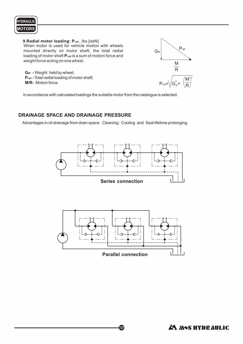
MOTORS
HYDRAULIC
9.Radial motor loading: P
P
,When motor is used for vehicle motion with wheels
mounted directly on motor shaft, the total radial
loading of motor shaft is a sum of motion force and
weight force acting on one wheel.
rad
rad
lbs [daN]
M
R
PradGW
P = G +rad
M
R2
W
2
G -W Weight held by wheel;
P -
M/R-
rad Total radial loading of motor shaft;
Motion force.
In accordance with calculated loadings the suitable motor from the catalogue is selected.
DRAINAGE SPACE AND DRAINAGE PRESSURE
Advantages in oil drainage from drain space: Cleaning; Cooling and Seal lifetime prolonging.
Parallel connection
Series connection
107

M+S Hydraulic warrants, that its products, supplied directly to original equipmentmanufacturer, authorized distributor or other customer, will be free of defects in material orworkmanship at the time of shipment from M+S Hydraulic and will conform to the productstechnical documentation (drawings and specifications) under sale agreement with Buyer.
This warranty will apply only to defects appearing within applicable Warranty period,mentioned below. If Buyer notifies M+S Hydraulic within the Warranty period about anysuch defects, M+S, at its sole option will replace or repair the defective products or theirparts found by M+S Hydraulic to be defective in material or workmanship.
THE FOREGOING LIMITED WARRANTY ISAVAILABLE ONLY IF “M+S HYDRAULIC”IS PROMPTLY NOTIFIED IN WRITTEN OF THE ALLEGED DEFECT AND DOES NOTCOVER FAILURE TO FUNCTION CAUSED BY DAMAGE TO THE PRODUCT,IMPROPER INSTALLATION, UNREASONABLE USE OR ABUSE OF THE PRODUCT,FAILURE TO PROVIDE OR USE OF IMPROPER MAINTENANCE OR USUAL,DEGRADATION OF THE PRODUCT DUE TO PHYSICAL ENVIRONMENTS OF ANUSUAL NATURE. THE FOREGOING REMEDIES ARE THE SOLE AND EXCLUSIVEREMEDIES AVAILABLE TO CUSTOMER. To facilitate the inspection, M+S Hydraulic mayrequire return of the product/part, which Buyer claims to be defective.
M+S Hydraulic shall not be liable for labor costs or any other expenses incurred duringthe disassembling or reinstalling of the product/part.
In case the claimed products are returned to M+S Hydraulic in bad condition: dirty,disassembled, with damaged or missing parts during transportation, the warranty will beconsidered as not applicable and the products will not be liable to repair.
The Warranty period is limited to 24 consecutive months (2 years) fromthe date of production of the product.
If the product is repaired in M+S Hydraulic during its warrantyperiod, the warranty period of the repaired item shall continue for the balance of originalWarranty period or for a period equal to 50% of the original new product Warranty period,whichever is later.
The Warranty period for Spare parts is 12 consecutive months (1 year)from the dispatch date of such parts from M+S Hydraulic.
LIMITATION OF LIABILITY M+S Hydraulic's liability for claim of any kind, for loss ordamage arising out of, connected with or resulting from an order, or from the performanceor branch thereof, or from the design, manufacture, sale delivery, operation or use of any ofits products shall be limited to, at M+S 's sole option, replacement, repair of any defectiveproduct or the issuance of a credit to Customer against any future purchases. Cashrefunds will not be made under any circumstances and Customer will not be entitled torecover any damages of any kind against M+S Hydraulic, including but not limited toincidental or consequential damages, whether direct or indirect, known or unknown,foreseen or unforeseen.
Warranty periods
New products:
Repaired products:
Spare parts:
WARRANTY

68, Kozloduy St., 6100 Kazanlak, BulgariaTel.: ++359 431 65167
++359 431 64271Fax: +359 431 64114
E-Mail: [email protected]: http://www.ms-hydraulic.com
Recommended


![MLHM MLHP MLHR MLHH...7 The function diagrams data is for average performance of randomly selected motors at back pressure 72.5÷145 PSI 5÷10 bar 150 SUS 32 mm²/s 122 F 50 C[ ] and](https://img.pdfslide.net/doc/110x75/5e6c3d76afd40c23af525af4/mlhm-mlhp-mlhr-7-the-function-diagrams-data-is-for-average-performance-of-randomly.jpg)