i
MODELLING OF LINEAR GENERATOR FOR
INTELLIGENT BUMPING SYSTEM
By
KOO SHUK YEE
DISSERTATION REPORT
Submitted to the Electrical & Electronics Engineering Programme
in Partial Fulfillment of the Requirements
for the Degree
Bachelor of Engineering (Hons)
(Electrical & Electronics Engineering)
Universiti Teknologi PETRONAS
Bandar Seri Iskandar
31750 Tronoh
Perak Darul Ridzuan
Copyright 2011
by
Koo Shuk Yee, 2011
brought to you by COREView metadata, citation and similar papers at core.ac.uk
provided by UTPedia
ii
CERTIFICATION OF APPROVAL
MODELLING OF LINEAR GENERATOR FOR
INTELLIGENT BUMPING SYSTEM
by
Koo Shuk Yee
Dissertation submitted to the
Electrical & Electronics Engineering Programme
Universiti Teknologi PETRONAS
in partial fulfilment of the requirement for the
Bachelor of Engineering (Hons)
(Electrical & Electronics Engineering)
Approved by,
__________________________
Dr. Taib Bin Ibrahim
Project Supervisor
UNIVERSITI TEKNOLOGI PETRONAS
TRONOH, PERAK
MAY 2011

iii
CERTIFICATION OF ORIGINALITY
This is to certify that I am responsible for the work submitted in this project,
that the original work is my own except as specified in the references and
acknowledgements, and that the original work contained herein have not been
undertaken or done by unspecified sources or persons.
__________________________
Koo Shuk Yee
iv
ABSTRACT
This report presents the designs of linear generators which can be
applied into the road bump of UTP. Universiti Teknologi PETRONAS consists
of more than 1000 cars and it should be able to apply a force on the linear
generator while car crossing the bump. The linear generator is able to produce
electricity when a force is applied to it. In the report, literature review of the
linear machine topology is included. Four types of linear machine are discussed
in the report and two designs of suitable linear generator are proposed. The
designs are set based on few criteria which are simplicity, performance and
suitability to be used in the road bump. The parameters of the proposed designs
are included and it is set according to the standard size of a road bump so that it
is able to be fitted perfectly into the road bump. Finite Element Analysis
method is applied to simulate and analyze the result by using ANSYS software.
The results of both designs are included whereby comparisons have been made
in terms of air gap flux density that is taken in air gap of the machine and also
the induced EMF. Besides, optimization work has been carried out in order to
obtain the maximum magnetic flux and also optimized design whereby
maximum EMF can be induced. Three areas have been optimized where
maximum magnetic flux can be obtained, balanced between electrical loading
and magnetic loading and also balanced between copper loss and iron loss. The
results of both designs about the magnetic flux in the stator and air gap flux are
discussed. Furthermore, a comparison on both designs is included as well. The
air gap flux induced in the linear generator is discussed and graphs are
included. In conclusion, a decision has been made to decide which design
should be chosen and applied in the road bump in order to increase the
performance of the road bump application to generate electricity.

v
ACKNOWLEDGEMENT
First and foremost, I would like to show my heartiest gratitude to my
Final Year Project supervisor, Dr. Taib Bin Ibrahim who has guided me
throughout the project by giving me suggestions and opinions until the
completion of the project. His professionalism and expertise has been helping
me to reach the current milestone of my project.
Besides, I would like to thank Dr. Nursyarizal Bin Mohd Nor and Dr
Mohd Shiraz Bin Aris who has guided me throughout the project by giving and
teaching me lots of knowledge in ANSYS software whereby I am able to use
the software to analyze my designs.
Last but not least, another heartfelt gratitude to my friends and family.
Without their support and consideration, I will not be able to complete the
project with this good result. THANK YOU.
vi
TABLE OF CONTENTS
CERTIFICATE OF APPROVAL………………………………………..…....i
CERTIFICATE OF ORIGINALITY………………...……………………….ii
ABSTRACT…………………..………………………………………..…........iii
ACKNOWLEDGEMENT…………………………………………..…...........iv
LIST OF FIGURES…….………………………………………………........viii
LIST OF TABLES……………………………………………………..…...….x
CHAPTER 1 INTRODUCTION ..................................................................... 1
1.1 Introduction ............................................................................ 1
1.2 Background of Study .............................................................. 1
1.3 Problem Statement .................................................................. 2
1.4 Objective and Scope of Study ................................................ 3
1.4.1 To fully utilize linear generator into the bumping
syste on the road of UTP ............................................... 3
1.4.2 To carry out literature review on linear machine
topology .......................................................................... 3
1.4.3 To propose new designs of linear generator to
improve the performance .............................................. 3
1.4.4 To analyze the suitable linear machine for bumping
system ............................................................................. 4
1.4.5 To optimize the design parameters ................................ 4
1.5 Conclusion .............................................................................. 4
CHAPTER 2 LITERATURE REVIEW ......................................................... 5
2.1 Introduction ............................................................................ 5
2.2 Basic Theory of Linear Generator .......................................... 5
2.2.1 Linear Induction Generator ........................................... 6
2.2.2 Linear DC Machine ....................................................... 7
2.2.3 Linear Synchronous Generator ...................................... 8
2.2.4 Linear Permanent Magnet Generator............................ 9
2.3 Previous Technology / Topology ......................................... 11
vii
2.4 Proposed Designs ................................................................. 12
2.4.1 Rectangular arrangement of permanent magnet ......... 12
2.4.2 Trapezoidal arrangement of permanent magnet .......... 14
2.5 Conclusion ............................................................................ 16
CHAPTER 3 METHODOLOGY .................................................................. 17
3.1 Introduction .......................................................................... 17
3.2 Procedure Identification ....................................................... 18
3.3 Design Parameters ................................................................ 19
3.3.1 Design with rectangular arrangement of permanent
magnet .......................................................................... 19
3.3.2 Design with trapezoidal arrangement of permanent
magnet .......................................................................... 21
3.4 Elements Determinations ...................................................... 22
3.4.1 Size of the road bump that determines the size of the
linear generator ........................................................... 23
3.4.2 Numbers of vehicles registered in UTP in year 2008
till 2010 ........................................................................ 23
3.4.3 Magnet ......................................................................... 23
3.4.4 Arrangement of permanent magnet.............................. 24
3.4.4.1 Trapezoidal arrangement of permanent
magnet……………………………………………....24
3.4.4.2 Rectangular arrangement of permanent
magnet…………………………………………..….. 25
3.5 Application Tool ................................................................... 26
3.6 Conclusion ............................................................................ 27
CHAPTER 4 RESULTS AND DISCUSSION .............................................. 28
4.1 Introduction .......................................................................... 28
4.2 Flux Distribution of Air- cored Magnetized Motor with
Rectangular Magnet .............................................................. 28
4.3 Flux Distribution of Air- cored Magnetized Motor with
Rectangular Magnet .............................................................. 30
4.4 Optimization – Both Designs of Linear Generator ............... 31
viii
4.4.1 Influence of Rm/ Re with respect to flux density ..… …31
4.4.1.1 Influence of Rm/ Re for rectangular
arrangement of permanent magnet…………….31
4.4.1.2 Influence of Rm/ Re for trapezoidal
arrangement of permanent magnet……….....….33
4.4.2 Influence of Tmr/ Tp with respect to flux density. …….35
4.4.2.1 Influence of Tmr/Tp for rectangular
arrangement of permanent magnet……..………..37
4.4.2.2 Influence of Tmr/Tp for trapezoidal
arrangement of permanent magnet……..………..37
4.4.3 Influence of Tw with respect to flux density …………...39
4.4.3.1 Influence of Tw for rectangular arrangement
of permanent magnet………...……….…………...39
4.4.3.2 Influence of Tw for trapezoidal arrangement
of permanent magnet… ......………………….…..41
4.5 Discussion ... ………………………………………………..43
4.5.1 Discussion on rectangular arrangement of
permanent magnet……………………...…………... ...... 43
4.5.2 Discussion on trapezoidal arrangement of
permanent magnet……………………………… ....... .46
4.6 Conclusion ............................................................................ 50
CHAPTER 5 CONCLUSION ........................................................................ 51
5.1 Conclusion ............................................................................ 51
5.2 Recommendation .................................................................. 52
5.2.1 New method to optimize the designs ............................ 52
5.2.2 Validate a prototype ..................................................... 52
GANTT CHART
ix
LIST OF FIGURES
Figure 1: Development of linear machine from rotary motor [1] ...................... 6
Figure 2: Rectangle arrangement of permanent magnet .................................. 13
Figure 3: 3D view of rectangular arrangement of permanent magnet linear
machine ............................................................................................ 13
Figure 4: Trapezoidal arrangement of permanent magnet ............................... 15
Figure 5: 3D view of trapezoidal arrangement of permanent magnet linear
machine ............................................................................................ 15
Figure 6: Project flow of designing linear generator ........................................ 18
Figure 7: Rectangular arrangement of quasi- Halbach permanent magnet ...... 19
Figure 8: Trapezoidal arrangement of quasi- Halbach permanent magnet ...... 21
Figure 9: Trapezoidal arrangement of quasi-Halbach PM in the centre .......... 24
Figure 10: Rectangular arrangement of quasi-Halbach PM ............................. 25
Figure 11: z = 0.0mm…………………………………………………. ......... 28
Figure 12: z = 20.0mm .................................................................................... 28
Figure 13: Air gap flux density reaches 1.0941T at z = 0.0mm ....................... 29
Figure 14: z = 0.0mm…………………………………………… ……………30
Figure 15: z = 20.0mm ..................................................................................... 30
Figure 16: Air gap flux density reaches 1.1314T at z = 0.0m .......................... 30
Figure 17: Ratio of Rm/ Re (rectangular design) with respect to flux density 32
Figure 18: Optimized ratio graph of rectangular design for Rm/ Re ............... 33
Figure 19: Ratio of Rm/ Re (trapezoidal design) with respect to flux density . 34
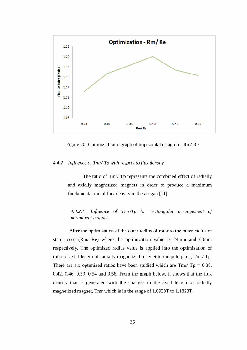
Figure 20: Optimized ratio graph of trapezoidal design for Rm/ Re ................ 35
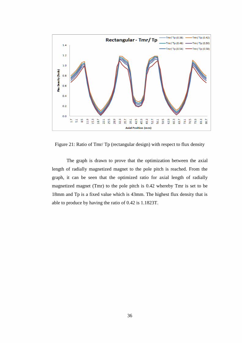
Figure 21: Ratio of Tmr/ Tp (rectangular design) with respect to flux density 36
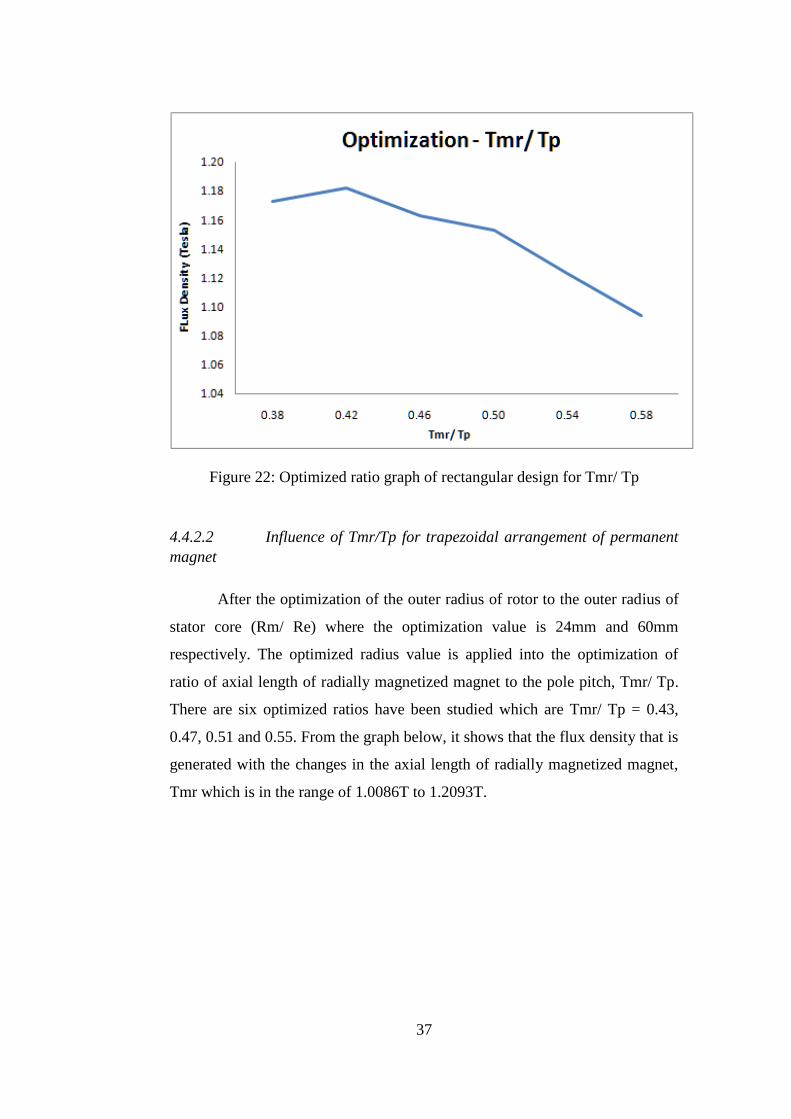
Figure 22: Optimized ratio graph of rectangular design for Tmr/ Tp .............. 37
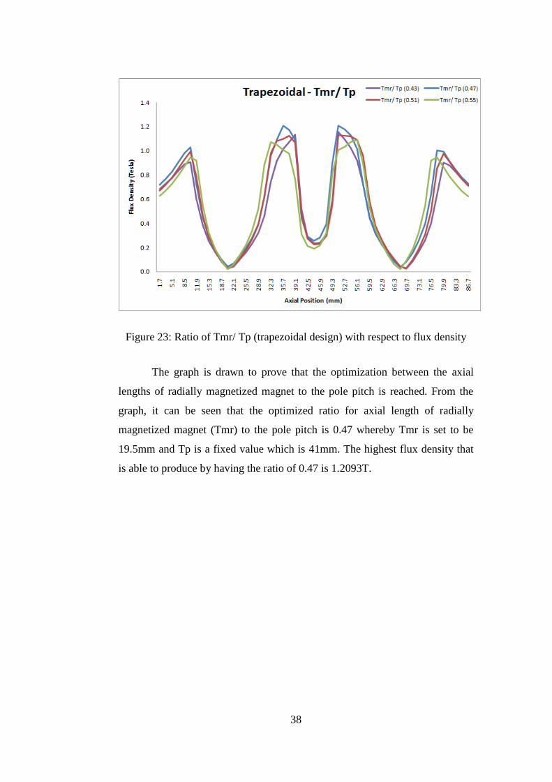
Figure 23: Ratio of Tmr/ Tp (trapezoidal design) with respect to flux density 38
Figure 24: Optimized ratio graph of trapezoidal design for Tmr/ Tp .............. 39
Figure 25: Size of Tw (rectangular design) with respect to flux density ......... 40
Figure 26: Optimized value graph of rectangular design for Tw ..................... 41
Figure 27: Size of Tw (trapezoidal design) with respect to flux density ......... 42
Figure 28: Optimized value graph of trapezoidal design for Tw ..................... 42

x
Figure 29: Difference between original parameters with optimum parameters 45
Figure 30: Difference between original parameters with optimum parameters 49
xi
LIST OF TABLES
Table 1: Initial design specification for linear generator with rectangular
arrangement of quasi- Halbach permanent magnet ............................ 20
Table 2: Initial design specification for linear generator with trapezoidal
arrangement of quasi- Halbach permanent magnet ............................ 22
Table 3: Size of road bump .............................................................................. 23
Table 4: Numbers of cars in UTP from year 2008 till 2010 ............................. 23
Table 5: Comparison of magnetic performance of Neodymium magnets
with other types of permanent magnets ............................................. 24
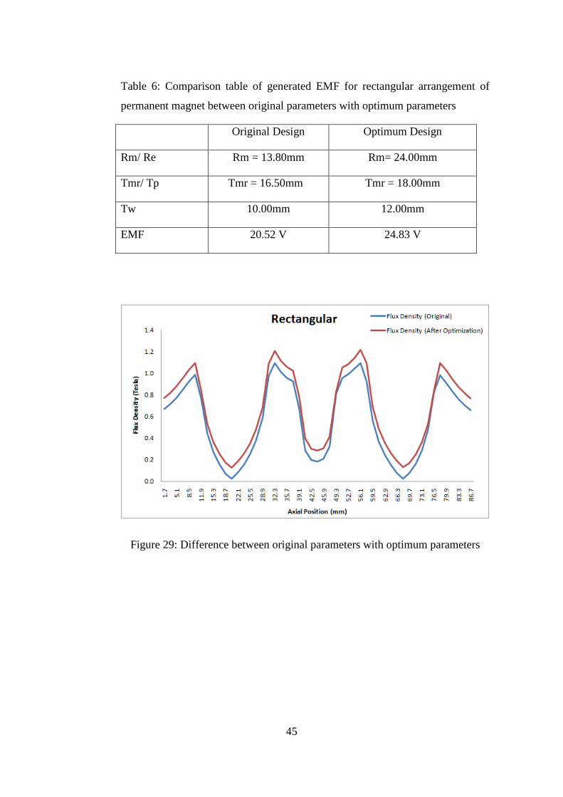
Table 6: Comparison table of generated EMF for rectangular arrangement
of permanent magnet between original parameters with
optimum parameters .......................................................................... 45
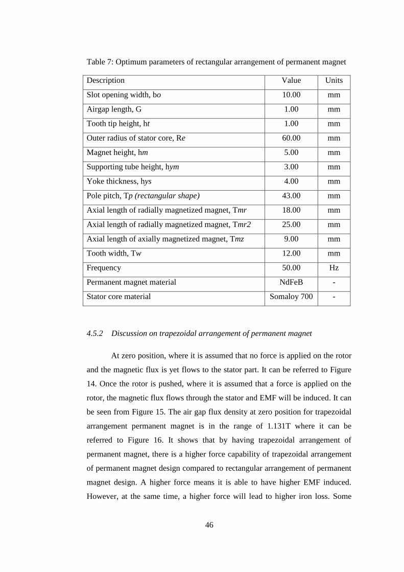
Table 7: Optimum parameters of rectangular arrangement of permanent
magnet ............................................................................................... 46
Table 8: Comparison table of generated EMF for trapezoidal arrangement
of permanent magnet between original parameters and
optimum parameters .......................................................................... 48
Table 9: Optimum parameters of trapezoidal arrangement of permanent
magnet ............................................................................................... 49
1
CHAPTER 1
INTRODUCTION
1.1 Introduction
This chapter involves the background study and main problem that
leads to the idea of designing and modeling of linear generators that is to be
applied into the road bump. The idea is to be focused on the area of Universiti
Teknologi PETRONAS whereby road bumps in UTP is the research and design
target.
1.2 Background of Study
Universiti Teknologi PETRONAS is a university where it contains of
more than 4000 students and 650 staffs in year 2011. The normal activities and
daily operations need a lot of electricity until UTP needs to pay at least RM 1.3
million for the electricity bill. The data is obtained from the Management
Department of UTP. To name a few, lecture hall needs electricity to turn on the
light, air-conditioner and projector for a normal lecture class, students stay in
hostel and electricity is needed to turn on the light and fan. Thus, the
consumption of electricity to maintain a daily operation of a university is huge.
A constant huge sum of supply of electricity is needed to provide to the UTP in
order for them to consume the electricity without any worries. The supply of
the electricity comes from three ways. One is by using non-renewable energy
like petroleum, coal and natural gases to generate electricity where it is
normally used in many countries includes Malaysia. Another way is generating
electricity by using renewable energy like solar, hydro and wind and of course,
lastly there should be a way for the user to generate electricity by using
2
generator and apply it into the facilities that is around us. For instances, user
can apply generator into the road bump and while car crosses the bump, the
force that is applied onto the generator will be able to generate electricity. The
rotating fan can be used as a generator to supply electricity to the other
electrical appliances while the fan is being turned on. For the current issue of
global warming, a better way to provide users the electricity is by using
renewable energy or using the facility around the users thus the users are no
longer needed to consume the electricity by using non- renewable energy and
in another hand, UTP is able to help the earth from going into deeper global
warming issue which it does bring a lot of troubles to the human.
1.3 Problem Statement
The global warming issue is a topic that everyone should take up the
responsibility to fix it as it brings a lot of disasters like flood, a sudden change
of climate and tsunami to the human. The problem happened is mainly due to
the excessive use of non- renewable energy to produce electricity and other
purposes. Thus, it is now the time to think of a better way likes using
renewable energy to generate electricity. The vehicles that cross the bump
along the roadside are able to produce a linear motion, while the car cross the
bump, the bump will go down as it will act as a spring where it is pressed and it
will move back to the original shape. The same concept is applied to the
bumping system where a linear generator will be put into the bump and while
the cars cross the bump, the motion of going down and up will act to the linear
generator and a certain amount of electricity will be produced. Moreover, there
are a lot of road bump in the compound of UTP that are not fully utilized. The
road bump in UTP can be used as the background to generate electricity by
using inserted a linear generator into the road bump.
By using linear generator under the road bumping system to generate
electricity is another good way to produce electricity by saving on the usage of
non- renewable energy. There are estimated 3700 vehicles include the cars and
motorcycles of the staffs, students and vendors in UTP in year 2010. The
crossing of the bump of all those cars is able to generate a huge sum amount of
3
electricity if a linear generator is applied into the bump. It is a way to generate
electricity by not using the non- renewable energy. In another word, it is a way
of harvesting the energy and produces it into a useful way.
1.4 Objective and Scope of Study
1.4.1 To fully utilize linear generator into the bumping system on the
road of UTP
It is be able to fully utilize the linear generator into the bumping system
on the road of UTP and so some force and energy that are produced by the cars
while crossing the bump can be changed into electrical energy and that
electricity can be used by UTP itself. From that point of view, this project helps
UTP on saving a lot of electricity and the usage of non- renewable energy to
generate electricity can be reduce.
1.4.2 To carry out literature review on linear machine topology
The concept of linear machine can be fully understood by studying on
literature review of linear machine topology. There are a few types of machine
available. Each has different characteristic and performance. A suitable type of
machine can be determined in order to apply into the new design machine.
1.4.3 To propose new designs of linear generator to improve the
performance
The concept of applying linear generator into the road bump will be
used thus the performance of the generator is importantly influencing the
electricity that can be generated. A few designs are designed and researched by
other scientists and researchers, the linear generator that is going to apply into
the road bump should have better design and performance in order to suit into
the road bump concept and be able to generate electricity at low speed. Hence,
a linear generator is studied and designed in order to come out with a linear
generator that is equivalently good at all specifications.
4
1.4.4 To analyze the suitable linear machine for bumping system
The simulation and analysis of the new design should be carried out in
order to make sure the new design meets the required performance and of
course, the new design should be able to fit into the road bump which it can
perform efficiently.
1.4.5 To optimize the design parameters
The new design should be verified and optimize in order to make sure
the design is working at its best performance. It can increase the credibility and
reliability of the design.
1.5 Conclusion
Due to the excessive usage of non- renewable energy that leads to
global warming issues arise, a green technology is to be used to generate
electricity by using road bumps with linear generator inserted under it. In UTP,
there are more than 20 road bumps and it should be fully utilized to generate
electricity. In order to make bring out this brilliant idea, a few methodologies
that need to be executed for instances, study on various topologies of linear
machines that is suitable to be applied into the road bump, to design and
improve from the initial design in order to generate higher electricity, to
optimize the designs in order to obtain the optimum number of flux and size of
linear machine.
5
CHAPTER 2
LITERATURE REVIEW
2.1 Introduction
This chapter involves the literature review on the various topologies of
the linear machine for instances linear synchronous machine, linear induction
machine, linear dc machine and linear permanent magnet machine. A suitable
linear machine will be chosen to be applied into the road bump. Two new
designs of chosen linear machine will be proposed in order to improve from its
initial performance.
2.2 Basic Theory of Linear Generator
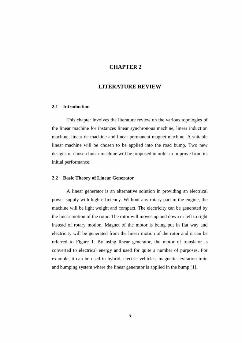
A linear generator is an alternative solution in providing an electrical
power supply with high efficiency. Without any rotary part in the engine, the
machine will be light weight and compact. The electricity can be generated by
the linear motion of the rotor. The rotor will moves up and down or left to right
instead of rotary motion. Magnet of the motor is being put in flat way and
electricity will be generated from the linear motion of the rotor and it can be
referred to Figure 1. By using linear generator, the motor of translator is
converted to electrical energy and used for quite a number of purposes. For
example, it can be used in hybrid, electric vehicles, magnetic levitation train
and bumping system where the linear generator is applied in the bump [1].
6
Figure 1: Development of linear machine from rotary motor [1]
2.3 Linear Machine Topologies
Various types of linear generators are available and each type of the
linear machines will have its own characteristic and suitability to be used in
order to generate electricity. Four types of linear machines will be discussed
and they are as following:
i. Linear Induction Generator
ii. Linear DC Machine
iii. Linear Synchronous Generator
iv. Linear Permanent Magnet Generator
2.3.1 Linear Induction Generator
A linear induction generator is basically an electric motor with its stator
unrolled and laid out in a line. Opposite of achieving torque by rotation, it
causes a linear force along the length of the stator. There are two design
categories of linear induction generator, low and high acceleration. The low
acceleration linear generators are of linear synchronous design. This means the
7
stator has a winding movement on one side of an air gap and a range of
alternate pole magnets on the other side. The energy is caused by a moving
electromagnetic field applied on conductors. The eddy currents of any
conductor appearing on the field will be induced. It is a synchronous machine.
The other design category is the high acceleration linear induction generator.
This means that the stator has an active three phase winding on one side of the
air gap and a passive conductor plate on the other side. It is hard to design and
will need a huge amount to manufacture it [2].
Advantage of using Linear Induction Generator [6]:
i. Apply in heavy industry for instance transportation and
conveyor system
ii. Size is huge
Disadvantage of using Linear Induction Generator [6]:
i. Motor has poor performance at low speed
ii. Normally used for three phase system
The application of linear induction machine is limited to heavy duty
performance machine and it is not recommended to be used under road bump
and generate electricity as this type of linear machine cannot provide a
performance at low speed.
2.3.2 Linear DC Machine
A DC motor is designed to run on DC electric power. By far, the most
common two types of DC motor are the brushed and brushless types which use
internal and external commutation respectively to create an oscillating AC
current from the DC source.
8
Advantage of using Linear DC Machine [6]:
i. DC linear motor is easy and accurate to control of force and
position
ii. Suitable to be used for long stroke applications
iii. Suitable to applied in robotics and positioning tables
Disadvantage of using Linear Induction Generator [6]:
i. Motor has poor performance at low speed
ii. Expensive to manufacture
iii. Suffer from brush wear
iv. High maintenance
v. Noisy during operation
For the application of low speed in road bump in order to generate
electricity, linear DC generator is not recommended to be used as it has poor
performance at low speed and it is expensive to manufacture and the
maintenance cost is proportionally higher.
2.3.3 Linear Synchronous Generator
It generates propulsive force by running current through a stator, which
creates an electro-magnetic field. This electro-magnetic field interacts with a
set of permanent magnets on a vehicle to create thrust. The permanent magnets
serve as the motor secondary, equivalent to a rotor in conventional motors
enabling linear motion. The vehicle is propelled by the moving electro-
magnetic field, travelling along as electric current is applied to the stator
beneath the vehicle. The vehicle’s movement is regulated by a sophisticated
control system incorporating state-of-the-art position sensing technology [7].
9
Advantages of using Linear Synchronous Machine [7]:
i. Increase reliability
ii. Improve performance on speed and efficiency
iii. Negotiate steep grades without depending on friction
iv. Eliminate the need to have propulsion power and control on the
vehicle
v. Ability to control multiple vehicles on complex trajectories
Disadvantages of using Linear Synchronous Machine [7]:
i. Poor performance at low speed
ii. Application is limited due to relative complexity of stator
winding
iii. Require power supply
For the application of using linear synchronous generator into the road
bump, it is not suitable to be used as the application is limited to the
complexity of the stator winding configuration and the need for a multi- phase
power supply makes the conventional topology of linear synchronous machine
un-suitable for low power reciprocating applications.
2.3.4 Linear Permanent Magnet Generator
Linear permanent magnet generator can be classified into three
categories which are moving- coil machine, moving- iron machine and
moving- magnet machine. They provide magnetic field for the machine coils.
The permanent magnet is used as the magnetic field source for the machine. It
gives a high flux density in the air gap compared to the other type. The designs
of the axial and radial permanent magnets had been used. In the axial
permanent magnet machine, a high cogging force is produced due to the
interaction between permanent magnet and stator teeth. Since it is a serious
problem, radial permanent magnet has been applied to reduce the cogging force
10
problem. As a result, a quasi Halbach permanent magnet is used [1]. The
efficiency and performance of the permanent magnet will be different if the
magnet is arranged in different way. According to the research, Neodymium
magnet is considered because it has higher remanence compare to other magnet
[3].
Disadvantages of moving coil [6]:
i. Difficulty in dissipating heat from coils
ii. Fragility of the connections and flying leads
iii. Limited access to moving coil
Disadvantages of moving iron [6]:
i. Heavy moving mass that can reduce the dynamic capability of
the motor
ii. A relatively low force capability due to low air- gap flux density
Advantages of moving magnet [6]:
i. Higher force capability
ii. Higher efficiency
A number of studies shown that linear permanent magnet machine is
able to perform well at low speed and it is very suitable to used for low power
reciprocating applications. Besides that, moving magnet linear machines can
offer higher efficiencies than moving coil linear machines [13]. Further, a
comparison between moving coil and moving magnet linear machine has
dedicated that the volume of magnet required for a moving coil is greater than
for a moving magnet linear machines of the same power. In addition, the
absence of flying leads to the armature makes moving magnet linear machines
11
more reliable and rugged, making them more suitable for higher duty operation
[9]. Thus, linear permanent magnet with category of moving magnet machine
is to be used for low power reciprocating application.
2.4 Previous Technology / Topology
Linear machine has been applied into a few areas. Piezoelectric is one
of the examples which it has the piezoelectric effect that it is understood as the
linear electromechanical interaction between the mechanical and the electrical
state in crystalline materials with no inversion symmetry [8].
Applications piezoelectric:
i. Electric cigarette lighter:
By pressing the button causes a spring-loaded hammer to hit a
piezoelectric crystal, producing a sufficiently high voltage
electric current that flows across a small spark gap, thus heating
and igniting the gas.
ii. A piezoelectric transformer:
An input voltage is applied across a short length of a bar of
piezoceramic material, creating an alternating stress in the bar
by the inverse piezoelectric effect and causing the whole bar to
vibrate.
Piezoelectric is not been used to for road bump application as it
generates low current compared to linear permanent magnet machine. Thus
linear permanent magnet machine is preferred in the application of road bump.
12
2.5 Proposed Designs
After the studied on the various types of linear machine, linear
permanent magnet machine is considered as the most suitable linear machine to
be applied into the road bump due to its characteristic and thus, further designs
will be proposed in order to improve its performance in terms of air gap flux
density.
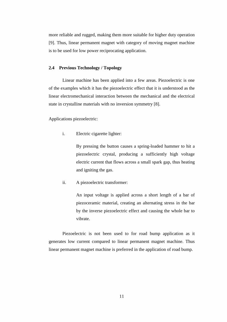
2.5.1 Rectangular arrangement of permanent magnet
There are a lot of choices to design for a good linear generator.
However, to make a perfect in efficiency, manufacturing cost and weight of the
linear generator, it can be said as very difficult to achieve. The research and
design that can be executed is only to optimize the existence design of linear
generator and make improvement in the configuration of the whole linear
generator. Thus, 2 designs and new configurations of quasi- Halbach
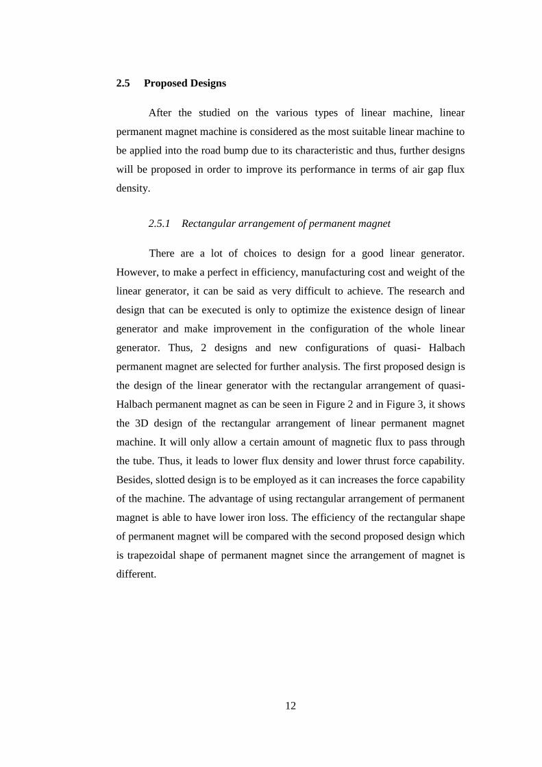
permanent magnet are selected for further analysis. The first proposed design is
the design of the linear generator with the rectangular arrangement of quasi-
Halbach permanent magnet as can be seen in Figure 2 and in Figure 3, it shows
the 3D design of the rectangular arrangement of linear permanent magnet
machine. It will only allow a certain amount of magnetic flux to pass through
the tube. Thus, it leads to lower flux density and lower thrust force capability.
Besides, slotted design is to be employed as it can increases the force capability
of the machine. The advantage of using rectangular arrangement of permanent
magnet is able to have lower iron loss. The efficiency of the rectangular shape
of permanent magnet will be compared with the second proposed design which
is trapezoidal shape of permanent magnet since the arrangement of magnet is
different.
13
Figure 2: Rectangle arrangement of permanent magnet
Figure 3: 3D view of rectangular arrangement of permanent magnet linear
machine
14
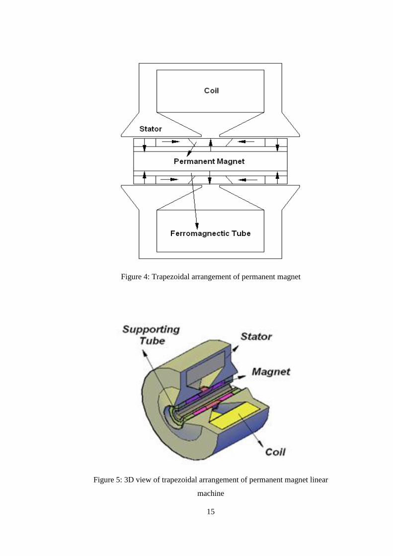
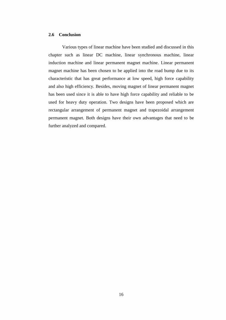
2.5.2 Trapezoidal arrangement of permanent magnet
Another proposed design is trapezoidal arrangement of permanent
magnet linear machine whereby the arrangement of trapezoidal magnet is
focused on the middle main magnet only since it is the focus to pass magnetic
flux through the coil. It is able to generate more magnetic flux. It can be
referred to Figure 4 where trapezoidal arrangement of permanent magnet can
be seen in the rotor part and Figure 5 shows the 3D view of trapezoidal
arrangement of linear permanent magnet machine. The number of magnetic
flux increases, thus, it leads to have better force capability of the linear
machine. Besides, this design is able to have higher voltage induced since it
has higher magnetic flux. However, the manufacturing cost of the permanent
magnet may be slightly higher than the rectangular arrangement permanent
magnet since the shape of permanent magnet needs to be custom made.
Besides, ferromagnetic tube will be used in the quasi- Halbach
magnetized shaft with rectangular and trapezoidal magnets since this results in
a stronger air-gap and therefore, a better force capability. Further, slotted
design is to be employed as it can increases the force capability of the machine.
15
Figure 4: Trapezoidal arrangement of permanent magnet
Figure 5: 3D view of trapezoidal arrangement of permanent magnet linear
machine
16
2.6 Conclusion
Various types of linear machine have been studied and discussed in this
chapter such as linear DC machine, linear synchronous machine, linear
induction machine and linear permanent magnet machine. Linear permanent
magnet machine has been chosen to be applied into the road bump due to its
characteristic that has great performance at low speed, high force capability
and also high efficiency. Besides, moving magnet of linear permanent magnet
has been used since it is able to have high force capability and reliable to be
used for heavy duty operation. Two designs have been proposed which are
rectangular arrangement of permanent magnet and trapezoidal arrangement
permanent magnet. Both designs have their own advantages that need to be
further analyzed and compared.
17
CHAPTER 3
METHODOLOGY
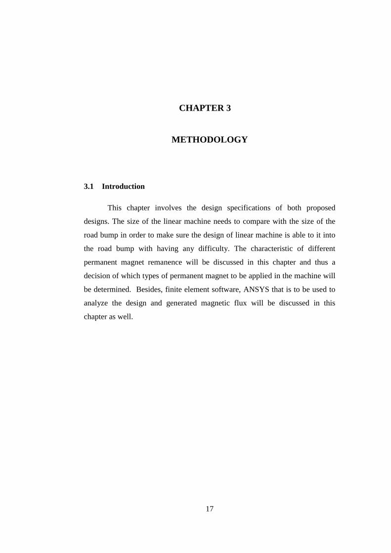
3.1 Introduction
This chapter involves the design specifications of both proposed
designs. The size of the linear machine needs to compare with the size of the
road bump in order to make sure the design of linear machine is able to it into
the road bump with having any difficulty. The characteristic of different
permanent magnet remanence will be discussed in this chapter and thus a
decision of which types of permanent magnet to be applied in the machine will
be determined. Besides, finite element software, ANSYS that is to be used to
analyze the design and generated magnetic flux will be discussed in this
chapter as well.
18
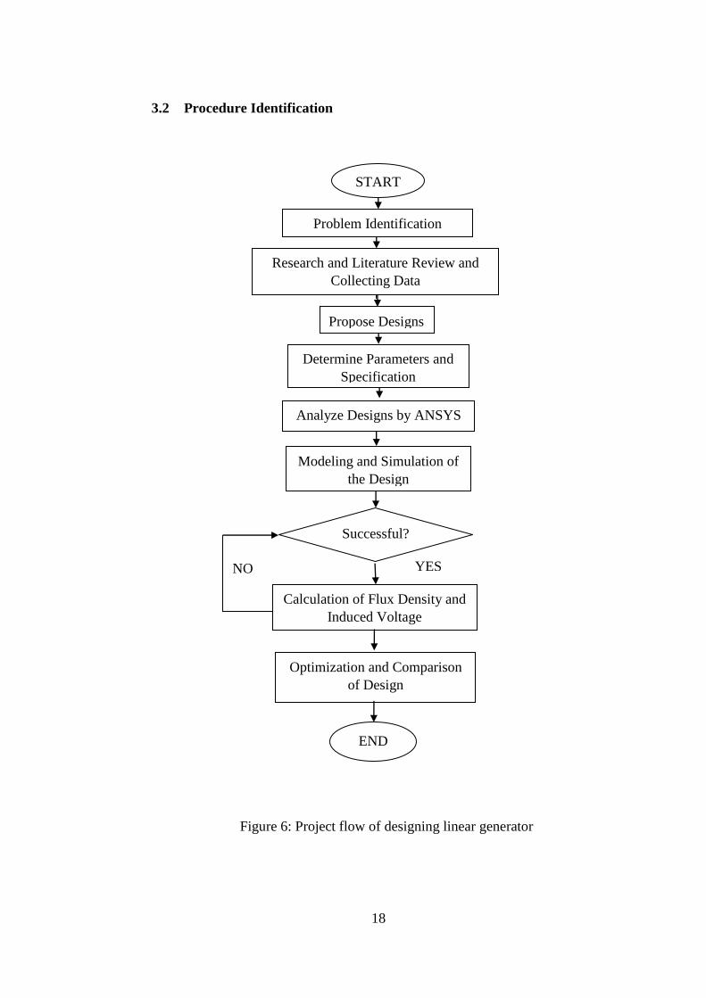
3.2 Procedure Identification
YES NO
Figure 6: Project flow of designing linear generator
Calculation of Flux Density and
Induced Voltage
Optimization and Comparison
of Design
END
START
Problem Identification
Research and Literature Review and
Collecting Data
Propose Designs
Determine Parameters and
Specification
Analyze Designs by ANSYS
Modeling and Simulation of
the Design
Successful?
19
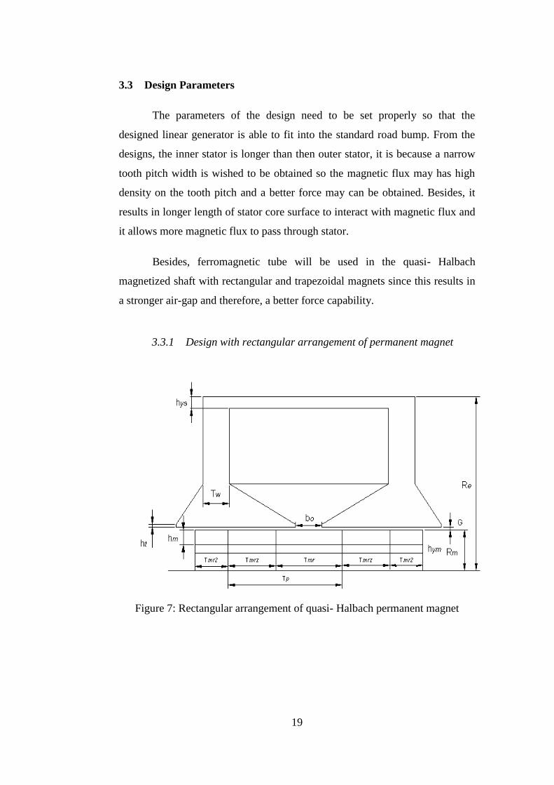
3.3 Design Parameters
The parameters of the design need to be set properly so that the
designed linear generator is able to fit into the standard road bump. From the
designs, the inner stator is longer than then outer stator, it is because a narrow
tooth pitch width is wished to be obtained so the magnetic flux may has high
density on the tooth pitch and a better force may can be obtained. Besides, it
results in longer length of stator core surface to interact with magnetic flux and
it allows more magnetic flux to pass through stator.
Besides, ferromagnetic tube will be used in the quasi- Halbach
magnetized shaft with rectangular and trapezoidal magnets since this results in
a stronger air-gap and therefore, a better force capability.
3.3.1 Design with rectangular arrangement of permanent magnet
Figure 7: Rectangular arrangement of quasi- Halbach permanent magnet
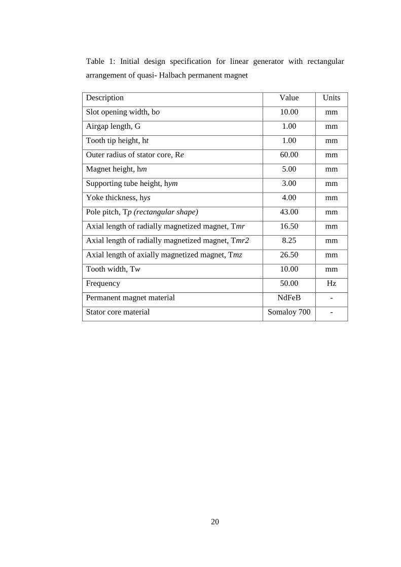
20
Table 1: Initial design specification for linear generator with rectangular
arrangement of quasi- Halbach permanent magnet
Description Value Units
Slot opening width, bo 10.00 mm
Airgap length, G 1.00 mm
Tooth tip height, ht 1.00 mm
Outer radius of stator core, Re 60.00 mm
Magnet height, hm 5.00 mm
Supporting tube height, hym 3.00 mm
Yoke thickness, hys 4.00 mm
Pole pitch, Tp (rectangular shape) 43.00 mm
Axial length of radially magnetized magnet, Tmr 16.50 mm
Axial length of radially magnetized magnet, Tmr2 8.25 mm
Axial length of axially magnetized magnet, Tmz 26.50 mm
Tooth width, Tw 10.00 mm
Frequency 50.00 Hz
Permanent magnet material NdFeB -
Stator core material Somaloy 700 -
21
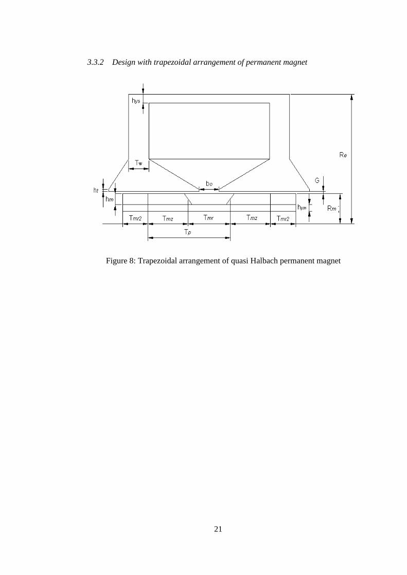
3.3.2 Design with trapezoidal arrangement of permanent magnet
Figure 8: Trapezoidal arrangement of quasi Halbach permanent magnet
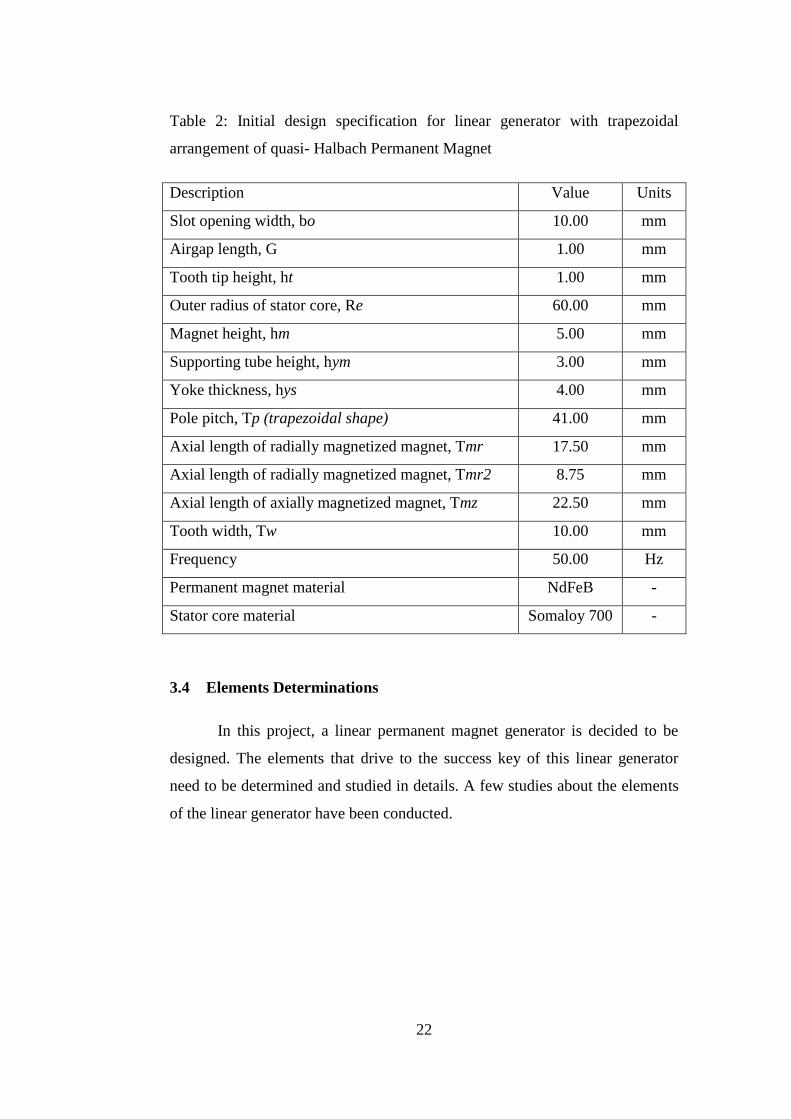
22
Table 2: Initial design specification for linear generator with trapezoidal
arrangement of quasi- Halbach Permanent Magnet
Description Value Units
Slot opening width, bo 10.00 mm
Airgap length, G 1.00 mm
Tooth tip height, ht 1.00 mm
Outer radius of stator core, Re 60.00 mm
Magnet height, hm 5.00 mm
Supporting tube height, hym 3.00 mm
Yoke thickness, hys 4.00 mm
Pole pitch, Tp (trapezoidal shape) 41.00 mm
Axial length of radially magnetized magnet, Tmr 17.50 mm
Axial length of radially magnetized magnet, Tmr2 8.75 mm
Axial length of axially magnetized magnet, Tmz 22.50 mm
Tooth width, Tw 10.00 mm
Frequency 50.00 Hz
Permanent magnet material NdFeB -
Stator core material Somaloy 700 -
3.4 Elements Determinations
In this project, a linear permanent magnet generator is decided to be
designed. The elements that drive to the success key of this linear generator
need to be determined and studied in details. A few studies about the elements
of the linear generator have been conducted.
23
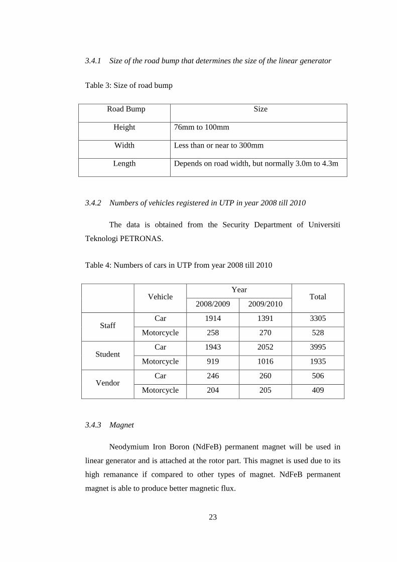
3.4.1 Size of the road bump that determines the size of the linear generator
Table 3: Size of road bump
Road Bump Size
Height 76mm to 100mm
Width Less than or near to 300mm
Length Depends on road width, but normally 3.0m to 4.3m
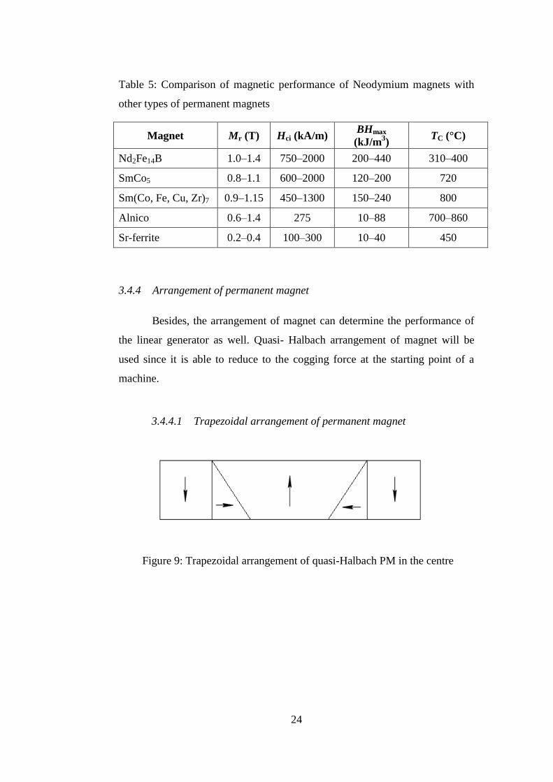
3.4.2 Numbers of vehicles registered in UTP in year 2008 till 2010
The data is obtained from the Security Department of Universiti
Teknologi PETRONAS.
Table 4: Numbers of cars in UTP from year 2008 till 2010
Vehicle Year
Total 2008/2009 2009/2010
Staff Car 1914 1391 3305
Motorcycle 258 270 528
Student Car 1943 2052 3995
Motorcycle 919 1016 1935
Vendor Car 246 260 506
Motorcycle 204 205 409
3.4.3 Magnet
Neodymium Iron Boron (NdFeB) permanent magnet will be used in
linear generator and is attached at the rotor part. This magnet is used due to its
high remanance if compared to other types of magnet. NdFeB permanent
magnet is able to produce better magnetic flux.
24
Table 5: Comparison of magnetic performance of Neodymium magnets with
other types of permanent magnets
Magnet Mr (T) Hci (kA/m) BHmax
(kJ/m3)
TC (°C)
Nd2Fe14B 1.0–1.4 750–2000 200–440 310–400
SmCo5 0.8–1.1 600–2000 120–200 720
Sm(Co, Fe, Cu, Zr)7 0.9–1.15 450–1300 150–240 800
Alnico 0.6–1.4 275 10–88 700–860
Sr-ferrite 0.2–0.4 100–300 10–40 450
3.4.4 Arrangement of permanent magnet
Besides, the arrangement of magnet can determine the performance of
the linear generator as well. Quasi- Halbach arrangement of magnet will be
used since it is able to reduce to the cogging force at the starting point of a
machine.
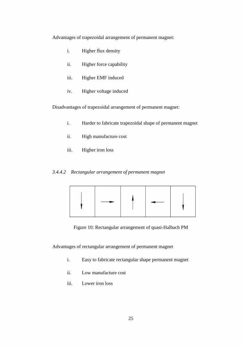
3.4.4.1 Trapezoidal arrangement of permanent magnet
Figure 9: Trapezoidal arrangement of quasi-Halbach PM in the centre
25
Advantages of trapezoidal arrangement of permanent magnet:
i. Higher flux density
ii. Higher force capability
iii. Higher EMF induced
iv. Higher voltage induced
Disadvantages of trapezoidal arrangement of permanent magnet:
i. Harder to fabricate trapezoidal shape of permanent magnet
ii. High manufacture cost
iii. Higher iron loss
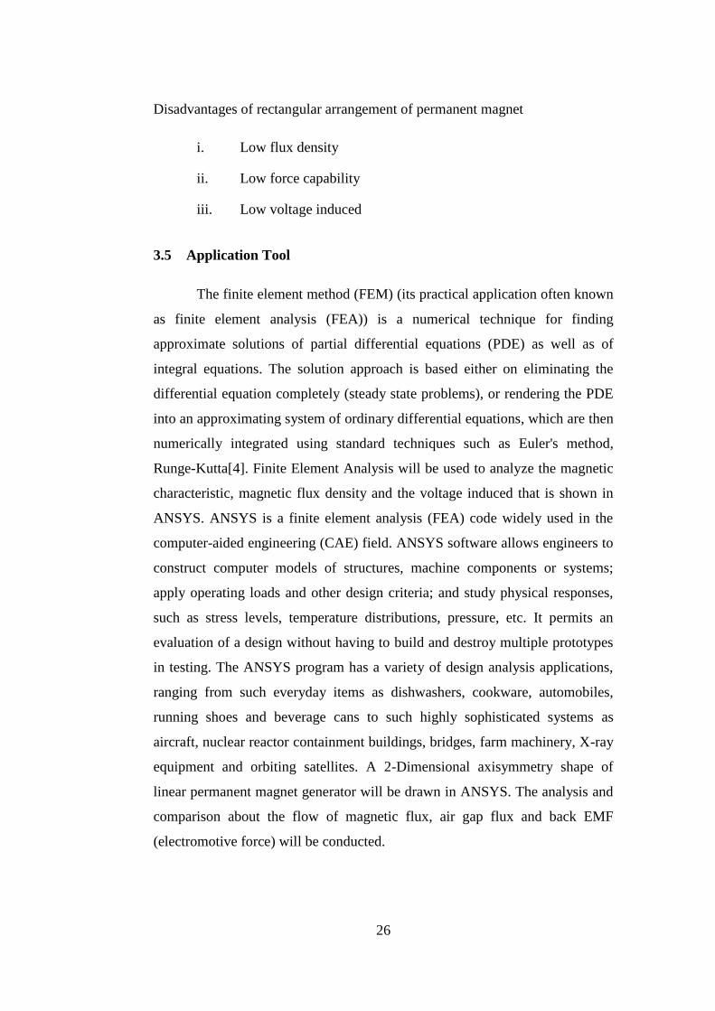
3.4.4.2 Rectangular arrangement of permanent magnet
Figure 10: Rectangular arrangement of quasi-Halbach PM
Advantages of rectangular arrangement of permanent magnet
i. Easy to fabricate rectangular shape permanent magnet
ii. Low manufacture cost
iii. Lower iron loss
26
Disadvantages of rectangular arrangement of permanent magnet
i. Low flux density
ii. Low force capability
iii. Low voltage induced
3.5 Application Tool
The finite element method (FEM) (its practical application often known
as finite element analysis (FEA)) is a numerical technique for finding
approximate solutions of partial differential equations (PDE) as well as of
integral equations. The solution approach is based either on eliminating the
differential equation completely (steady state problems), or rendering the PDE
into an approximating system of ordinary differential equations, which are then
numerically integrated using standard techniques such as Euler's method,
Runge-Kutta[4]. Finite Element Analysis will be used to analyze the magnetic
characteristic, magnetic flux density and the voltage induced that is shown in
ANSYS. ANSYS is a finite element analysis (FEA) code widely used in the
computer-aided engineering (CAE) field. ANSYS software allows engineers to
construct computer models of structures, machine components or systems;
apply operating loads and other design criteria; and study physical responses,
such as stress levels, temperature distributions, pressure, etc. It permits an
evaluation of a design without having to build and destroy multiple prototypes
in testing. The ANSYS program has a variety of design analysis applications,
ranging from such everyday items as dishwashers, cookware, automobiles,
running shoes and beverage cans to such highly sophisticated systems as
aircraft, nuclear reactor containment buildings, bridges, farm machinery, X-ray
equipment and orbiting satellites. A 2-Dimensional axisymmetry shape of
linear permanent magnet generator will be drawn in ANSYS. The analysis and
comparison about the flow of magnetic flux, air gap flux and back EMF
(electromotive force) will be conducted.
27
3.6 Conclusion
The initial specifications of the both designs have been discussed. The
characteristic of the permanent magnet have been determined whereby
Neodymium Iron Boron (NdFeB) will be used as the permanent magnet in the
design as it has highest remanence compared to the other of magnet and it is
able to have higher magnetic flux. The advantages and disadvantages of the
arrangement of rectangular and trapezoidal shape of permanent magnet have
been discussed. It shows that trapezoidal shape of permanent magnet is able to
have higher force capability, higher efficiency, higher flux density and higher
induced EMF. For rectangular shape of permanent magnet, it is easy to
manufacture and thus it reduces the manufacturing cost. Finite element
software, ANSYS has been used to analyze the design. It is able to determine
the magnetic flux and air gap flux density in the design.
28
CHAPTER 4
RESULTS AND DISCUSSION
4.1 Introduction
This chapter illustrates the results and discussion on linear generators
which are proposed in Chapter 3 whereby the results are concentrated in air
gap flux density and induced Electromotive force (EMF). Besides, the
optimization of the linear generator is discussed.
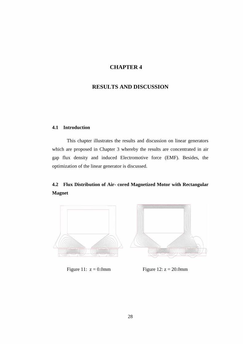
4.2 Flux Distribution of Air- cored Magnetized Motor with Rectangular
Magnet
Figure 11: z = 0.0mm Figure 12: z = 20.0mm
29
Figure 11 and 12 show air gap flux distributions corresponding to two
armature positions which are zero displacement and the maximum stroke
position. As will be seen, leakage flux in the inner bore of the air- cored quasi-
Halbach magnetized armature with the rectangular magnets is relatively small,
which justifies the use of a non- magnetic support tube [9].
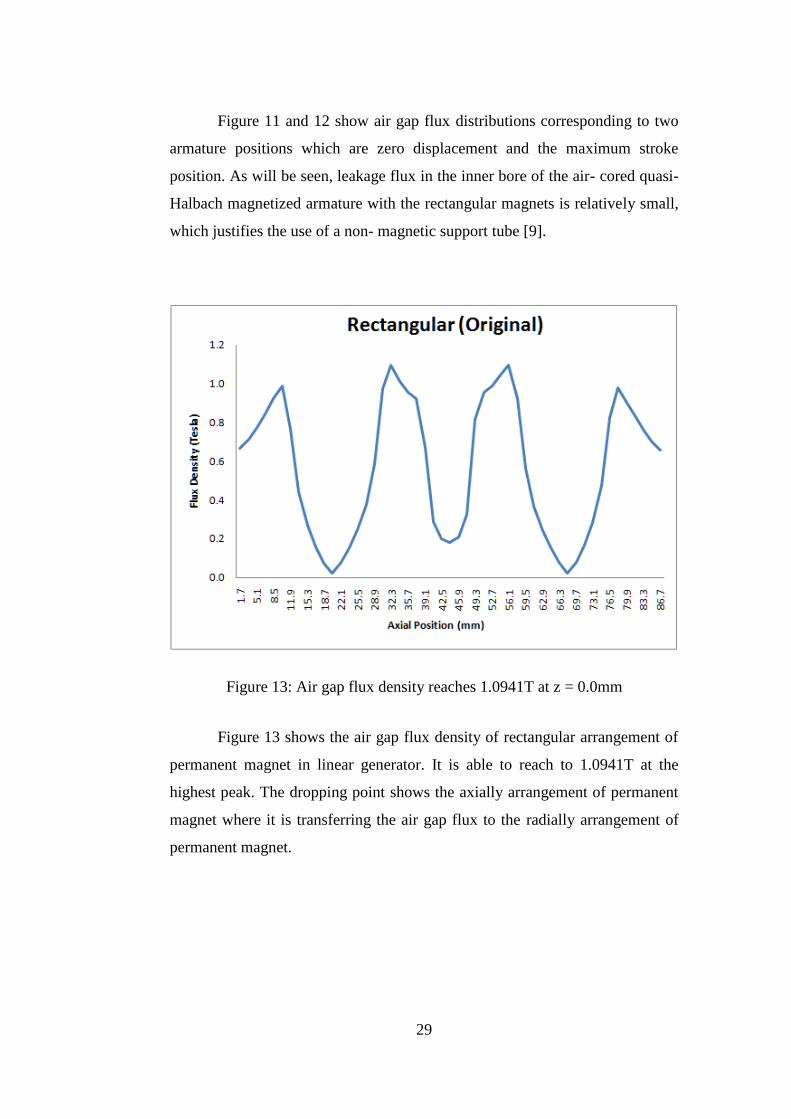
Figure 13: Air gap flux density reaches 1.0941T at z = 0.0mm
Figure 13 shows the air gap flux density of rectangular arrangement of
permanent magnet in linear generator. It is able to reach to 1.0941T at the
highest peak. The dropping point shows the axially arrangement of permanent
magnet where it is transferring the air gap flux to the radially arrangement of
permanent magnet.
30
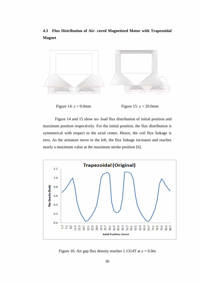
4.3 Flux Distribution of Air- cored Magnetized Motor with Trapezoidal
Magnet
Figure 14: z = 0.0mm Figure 15: z = 20.0mm
Figure 14 and 15 show no- load flux distribution of initial position and
maximum position respectively. For the initial position, the flux distribution is
symmetrical with respect to the axial centre. Hence, the coil flux linkage is
zero. As the armature move to the left, the flux linkage increases and reaches
nearly a maximum value at the maximum stroke position [6].
Figure 16: Air gap flux density reaches 1.1314T at z = 0.0m
31
Figure 16 shows the air gap flux density of rectangular arrangement of
permanent magnet in linear generator. It is able to reach to 1.1314T at the
highest peak. The dropping point shows the axially arrangement of permanent
magnet where it is transferring the air gap flux to the radially arrangement of
permanent magnet.
4.4 Optimization – Both Designs of Linear Generator
Optimization work will be carried out to three main areas:
i. The ratio of outer radius of rotor to outer radius of stator core,
Rm/ Re
ii. The ratio of axial length of radially magnetized magnet to pole
pitch, Tmr/ Tp
iii. Tooth width, Tw
4.4.1 Influence of Rm/ Re with respect to flux density
The ratio of Rm/ Re represents the optimal balance between electrical
loading and magnetic loading in order to achieve maximum motor efficiency
[10]. In this study, the air gap flux density is optimized with respect to this
ratio.
4.4.1.1 Influence of Rm/ Re for rectangular arrangement of
permanent magnet
There are six optimized ratios have been studied which are Rm/ Re =
0.23, 0.30, 0.35, 0.40, 0.45 and 0.50. From the graph below, it shows that the
flux density that is generated with the changes in the outer radius of rotor, Rm
which is in the range of 1.0901T to 1.1471T.
32
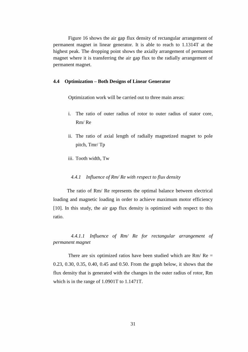
Figure 17: Ratio of Rm/ Re (rectangular design) with respect to flux density
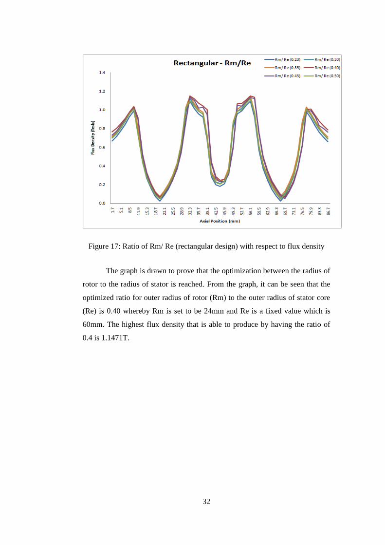
The graph is drawn to prove that the optimization between the radius of
rotor to the radius of stator is reached. From the graph, it can be seen that the
optimized ratio for outer radius of rotor (Rm) to the outer radius of stator core
(Re) is 0.40 whereby Rm is set to be 24mm and Re is a fixed value which is
60mm. The highest flux density that is able to produce by having the ratio of
0.4 is 1.1471T.
33
Figure 18: Optimized ratio graph of rectangular design for Rm/ Re
4.4.1.2 Influence of Rm/ Re for trapezoidal arrangement of permanent
magnet
There are six optimized ratios have been studied which are Rm/ Re =
0.23, 0.30, 0.35, 0.40, 0.45, 0.50. From the graph below, it shows that the flux
density that is generated with the changes in the outer radius of rotor, Rm
which is in the range of 1.1314T to 1.200T.
34
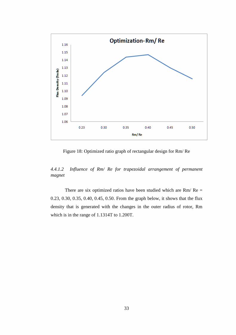
Figure 19: Ratio of Rm/ Re (trapezoidal design) with respect to flux density
The graph is drawn to prove that the optimization between the radius of
rotor to the radius of stator is reached. From the graph, it can be seen that the
optimized ratio for outer radius of rotor (Rm) to the outer radius of stator core
(Re) is 0.40 whereby Rm is set to be 24mm and Re is a fixed value which is
60mm. The highest flux density that is able to produce by having the ratio of
0.4 is 1.200T.
35
Figure 20: Optimized ratio graph of trapezoidal design for Rm/ Re
4.4.2 Influence of Tmr/ Tp with respect to flux density
The ratio of Tmr/ Tp represents the combined effect of radially
and axially magnetized magnets in order to produce a maximum
fundamental radial flux density in the air gap [11].
4.4.2.1 Influence of Tmr/Tp for rectangular arrangement of
permanent magnet
After the optimization of the outer radius of rotor to the outer radius of
stator core (Rm/ Re) where the optimization value is 24mm and 60mm
respectively. The optimized radius value is applied into the optimization of
ratio of axial length of radially magnetized magnet to the pole pitch, Tmr/ Tp.
There are six optimized ratios have been studied which are Tmr/ Tp = 0.38,
0.42, 0.46, 0.50, 0.54 and 0.58. From the graph below, it shows that the flux
density that is generated with the changes in the axial length of radially
magnetized magnet, Tmr which is in the range of 1.0938T to 1.1823T.
36
Figure 21: Ratio of Tmr/ Tp (rectangular design) with respect to flux density
The graph is drawn to prove that the optimization between the axial
length of radially magnetized magnet to the pole pitch is reached. From the
graph, it can be seen that the optimized ratio for axial length of radially
magnetized magnet (Tmr) to the pole pitch is 0.42 whereby Tmr is set to be
18mm and Tp is a fixed value which is 43mm. The highest flux density that is
able to produce by having the ratio of 0.42 is 1.1823T.
37
Figure 22: Optimized ratio graph of rectangular design for Tmr/ Tp
4.4.2.2 Influence of Tmr/Tp for trapezoidal arrangement of permanent
magnet
After the optimization of the outer radius of rotor to the outer radius of
stator core (Rm/ Re) where the optimization value is 24mm and 60mm
respectively. The optimized radius value is applied into the optimization of
ratio of axial length of radially magnetized magnet to the pole pitch, Tmr/ Tp.
There are six optimized ratios have been studied which are Tmr/ Tp = 0.43,
0.47, 0.51 and 0.55. From the graph below, it shows that the flux density that is
generated with the changes in the axial length of radially magnetized magnet,
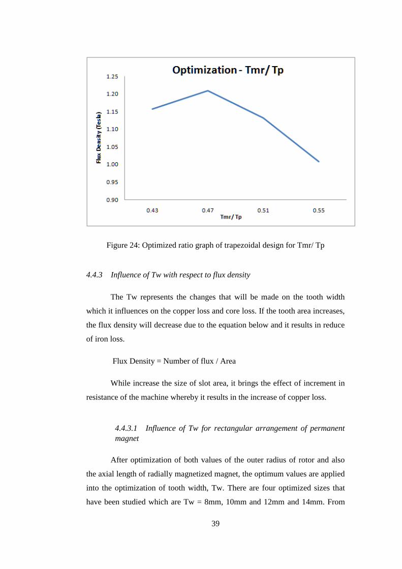
Tmr which is in the range of 1.0086T to 1.2093T.
38
Figure 23: Ratio of Tmr/ Tp (trapezoidal design) with respect to flux density
The graph is drawn to prove that the optimization between the axial
lengths of radially magnetized magnet to the pole pitch is reached. From the
graph, it can be seen that the optimized ratio for axial length of radially
magnetized magnet (Tmr) to the pole pitch is 0.47 whereby Tmr is set to be
19.5mm and Tp is a fixed value which is 41mm. The highest flux density that
is able to produce by having the ratio of 0.47 is 1.2093T.
39
Figure 24: Optimized ratio graph of trapezoidal design for Tmr/ Tp
4.4.3 Influence of Tw with respect to flux density
The Tw represents the changes that will be made on the tooth width
which it influences on the copper loss and core loss. If the tooth area increases,
the flux density will decrease due to the equation below and it results in reduce
of iron loss.
Flux Density = Number of flux / Area
While increase the size of slot area, it brings the effect of increment in
resistance of the machine whereby it results in the increase of copper loss.
4.4.3.1 Influence of Tw for rectangular arrangement of permanent
magnet
After optimization of both values of the outer radius of rotor and also
the axial length of radially magnetized magnet, the optimum values are applied
into the optimization of tooth width, Tw. There are four optimized sizes that
have been studied which are Tw = 8mm, 10mm and 12mm and 14mm. From
40
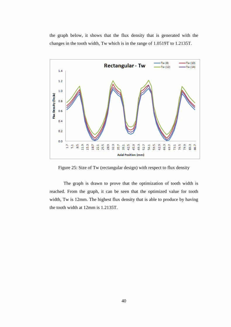
the graph below, it shows that the flux density that is generated with the
changes in the tooth width, Tw which is in the range of 1.0519T to 1.2135T.
Figure 25: Size of Tw (rectangular design) with respect to flux density
The graph is drawn to prove that the optimization of tooth width is
reached. From the graph, it can be seen that the optimized value for tooth
width, Tw is 12mm. The highest flux density that is able to produce by having
the tooth width at 12mm is 1.2135T.
41
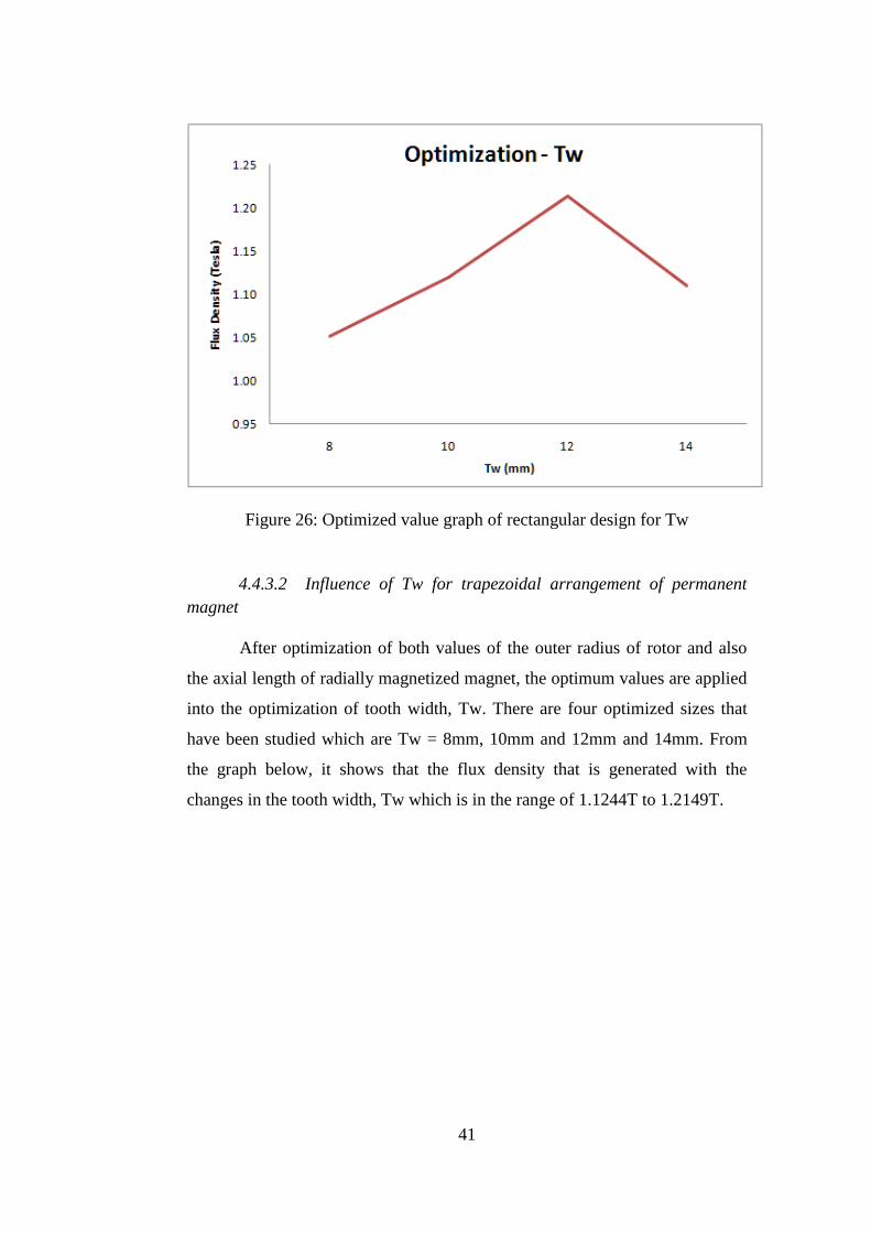
Figure 26: Optimized value graph of rectangular design for Tw
4.4.3.2 Influence of Tw for trapezoidal arrangement of permanent
magnet
After optimization of both values of the outer radius of rotor and also
the axial length of radially magnetized magnet, the optimum values are applied
into the optimization of tooth width, Tw. There are four optimized sizes that
have been studied which are Tw = 8mm, 10mm and 12mm and 14mm. From
the graph below, it shows that the flux density that is generated with the
changes in the tooth width, Tw which is in the range of 1.1244T to 1.2149T.
42
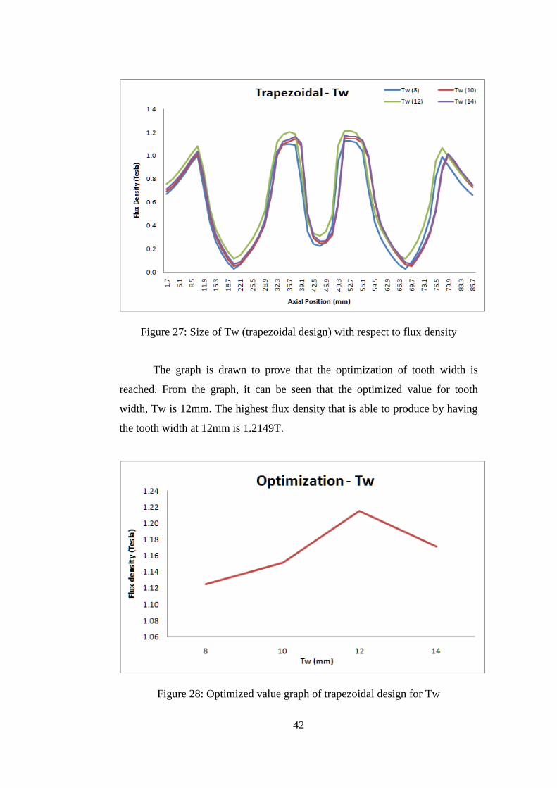
Figure 27: Size of Tw (trapezoidal design) with respect to flux density
The graph is drawn to prove that the optimization of tooth width is
reached. From the graph, it can be seen that the optimized value for tooth
width, Tw is 12mm. The highest flux density that is able to produce by having
the tooth width at 12mm is 1.2149T.
Figure 28: Optimized value graph of trapezoidal design for Tw
43
4.5 Discussion
The new design of linear generator should have a result where it can
reach a good performance when it is applied into the road bump and it can be
fitted perfectly into the road bump as well. In the meantime, it is able to generate
electricity when car crosses on the road bump. Though there are pros and cons of
the design, a balance point of the design should be made. It means, in terms of
performance, the best linear generator should be chosen, however, the
manufacture cost needs to be considered as well. Thus, an optimization task and
re- justification work is carried out.
4.5.1 Discussion on rectangular arrangement of permanent magnet
At zero position, where it is assumed that no force is applied on the rotor
and the magnetic flux is yet flows to the stator part. It can be referred to Figure
11. Once the rotor is pushed, where it is assumed that a force is applied on the
rotor, the magnetic flux flows through the stator and EMF will be induced. It can
be seen from Figure 12. The air gap flux density at zero position for rectangular
arrangement permanent magnet is in the range of 1.094T where it can be
referred to Figure 13. It has lower flux density compared to trapezoidal
arrangement of permanent magnet design. Thus, it has lower force capability and
it cannot generate high voltage. However, lower force does have its advantage.
The design with lower force capability means it has lower iron loss. Some
assumptions have been made to estimate the induced EMF (E) that will be
generated in rectangular shape of permanent magnet design by using the
following formula [12]:
E = 4.44 f BAN
Where,
f = frequency, 50 Hz
B = flux density generated
44
A = area of magnet (5.0mm x 16.5mm)
N = number of turns of coil
Thus,
E = 4.44 (50) (1.094) (82.5 x 10^-6) (1024)
= 20.52 V
There are three areas where changes have been done on the rectangular
arrangement of magnet design. The optimization and modification on the tooth
width (Tw), outer radius of rotor (Rm) and axial length of radially magnetized
magnet (Tmr) on rectangular design are carried out. The result of the induced
EMF has a significant increase. By applying the same formula, the induced EMF
can be compared.
E = 4.44 f BAN
Where,
f = frequency, 50 Hz
B = flux density generated
A = area of magnet (5.0mm x 18.0mm)
N = number of turns of coil
Thus,
E = 4.44 (50) (1.2135) (0.9 x 10^-4) (1024)
= 24.83 V
45
Table 6: Comparison table of generated EMF for rectangular arrangement of
permanent magnet between original parameters with optimum parameters
Original Design Optimum Design
Rm/ Re Rm = 13.80mm Rm= 24.00mm
Tmr/ Tp Tmr = 16.50mm Tmr = 18.00mm
Tw 10.00mm 12.00mm
EMF 20.52 V 24.83 V
Figure 29: Difference between original parameters with optimum parameters
46
Table 7: Optimum parameters of rectangular arrangement of permanent magnet
Description Value Units
Slot opening width, bo 10.00 mm
Airgap length, G 1.00 mm
Tooth tip height, ht 1.00 mm
Outer radius of stator core, Re 60.00 mm
Magnet height, hm 5.00 mm
Supporting tube height, hym 3.00 mm
Yoke thickness, hys 4.00 mm
Pole pitch, Tp (rectangular shape) 43.00 mm
Axial length of radially magnetized magnet, Tmr 18.00 mm
Axial length of radially magnetized magnet, Tmr2 25.00 mm
Axial length of axially magnetized magnet, Tmz 9.00 mm
Tooth width, Tw 12.00 mm
Frequency 50.00 Hz
Permanent magnet material NdFeB -
Stator core material Somaloy 700 -
4.5.2 Discussion on trapezoidal arrangement of permanent magnet
At zero position, where it is assumed that no force is applied on the rotor
and the magnetic flux is yet flows to the stator part. It can be referred to Figure
14. Once the rotor is pushed, where it is assumed that a force is applied on the
rotor, the magnetic flux flows through the stator and EMF will be induced. It can
be seen from Figure 15. The air gap flux density at zero position for trapezoidal
arrangement permanent magnet is in the range of 1.131T where it can be
referred to Figure 16. It shows that by having trapezoidal arrangement of
permanent magnet, there is a higher force capability of trapezoidal arrangement
of permanent magnet design compared to rectangular arrangement of permanent
magnet design. A higher force means it is able to have higher EMF induced.
However, at the same time, a higher force will lead to higher iron loss. Some
47
assumptions have been made to estimate the induced EMF (E) that will be
generated in trapezoidal shape of permanent magnet design by using the
following formula [12]:
E = 4.44 f BAN
Where,
f = frequency, 50 Hz
B = flux density generated
A = area of magnet (0.5 x 25.0mm x 10.0mm)
N = number of turns of coil
Thus,
E = 4.44 (50) (1.131) (1.25 x 10^-4) (1024)
= 32.15 V
There are three areas where changes have been done on the trapezoidal
arrangement of magnet design. The optimization and modification on the tooth
width (Tw), outer radius of rotor (Rm) and axial length of radially magnetized
magnet (Tmr) on trapezoidal design are carried out. The result of the induced
EMF has a significant increase. By applying the same formula, the induced EMF
can be compared.
E = 4.44 f BAN
Where,
f = frequency, 50 Hz
48
B = flux density generated
A = area of magnet (0.5 x 25.0mm x 14.0mm)
N = number of turns of coil
Thus,
E = 4.44 (50) (1.2149) (1.75 x 10^-4) (1024)
= 48.33 V
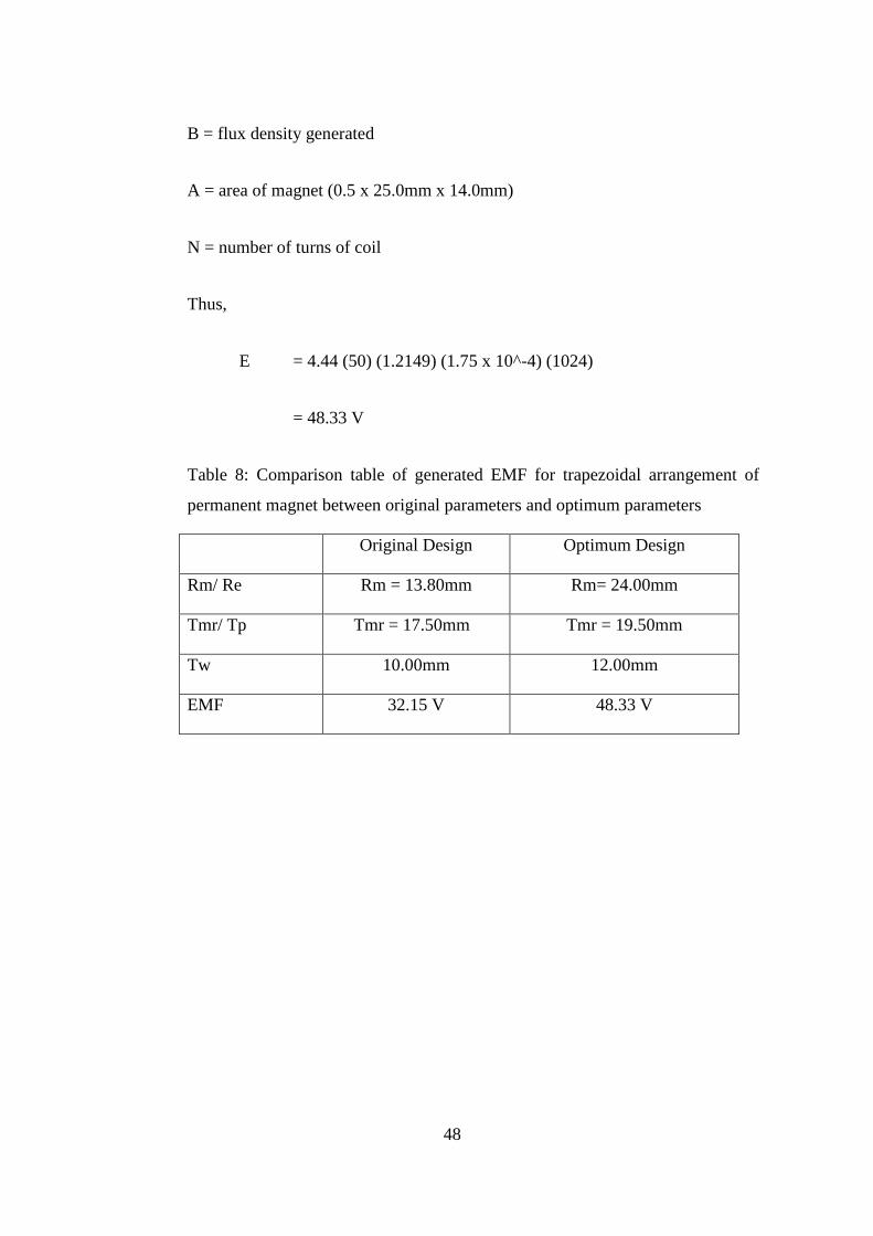
Table 8: Comparison table of generated EMF for trapezoidal arrangement of
permanent magnet between original parameters and optimum parameters
Original Design Optimum Design
Rm/ Re Rm = 13.80mm Rm= 24.00mm
Tmr/ Tp Tmr = 17.50mm Tmr = 19.50mm
Tw 10.00mm 12.00mm
EMF 32.15 V 48.33 V
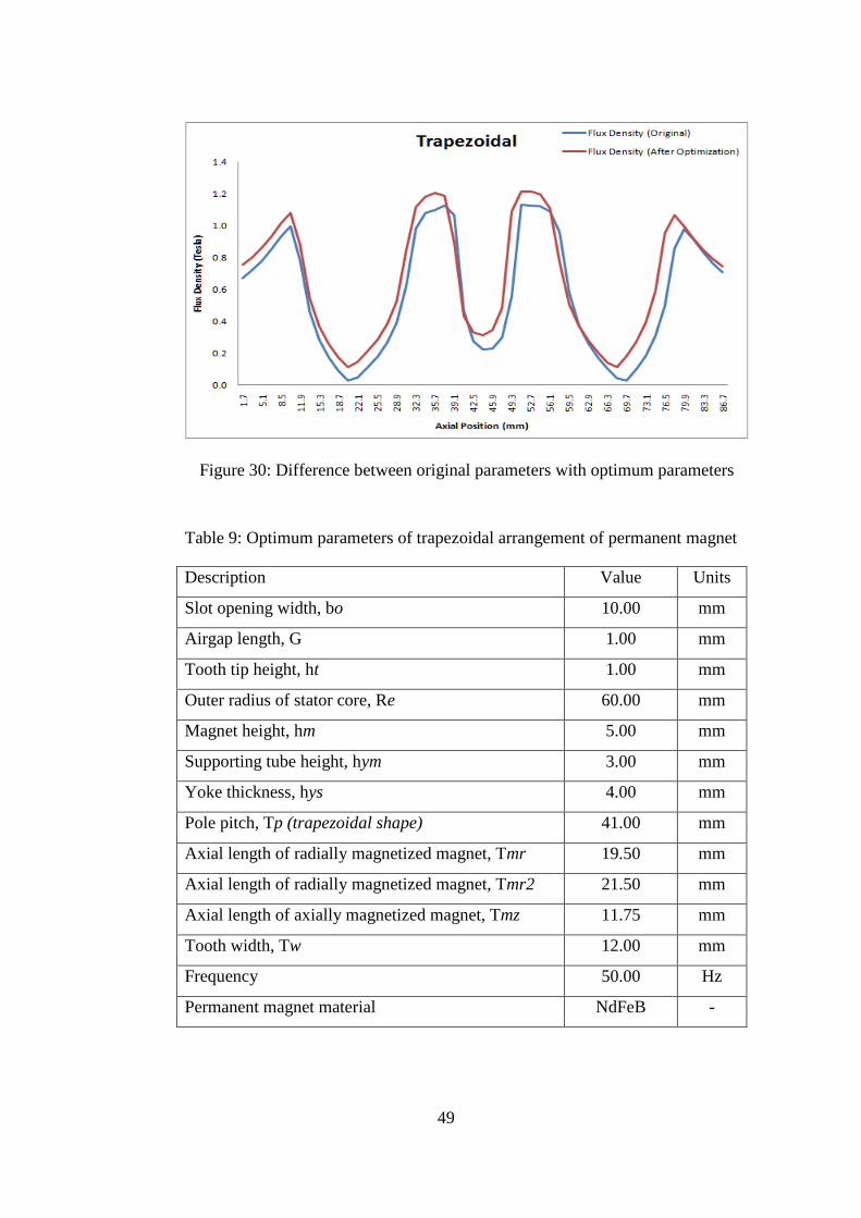
49
Figure 30: Difference between original parameters with optimum parameters
Table 9: Optimum parameters of trapezoidal arrangement of permanent magnet
Description Value Units
Slot opening width, bo 10.00 mm
Airgap length, G 1.00 mm
Tooth tip height, ht 1.00 mm
Outer radius of stator core, Re 60.00 mm
Magnet height, hm 5.00 mm
Supporting tube height, hym 3.00 mm
Yoke thickness, hys 4.00 mm
Pole pitch, Tp (trapezoidal shape) 41.00 mm
Axial length of radially magnetized magnet, Tmr 19.50 mm
Axial length of radially magnetized magnet, Tmr2 21.50 mm
Axial length of axially magnetized magnet, Tmz 11.75 mm
Tooth width, Tw 12.00 mm
Frequency 50.00 Hz
Permanent magnet material NdFeB -
50
4.6 Conclusion
The trapezoidal permanent magnet design is able to focus more flux in
the center and transfer it to the stator and thus it leads to higher flux density and
higher induced EMF obtained. Besides, the overall performance has increased
after the optimization work has been executed. For trapezoidal design of
permanent magnet, the overall performance has increased 50% in the induced
EMF meanwhile, for rectangular design of permanent magnet increases 21% in
the induced EMF.
51
CHAPTER 5
CONCLUSION
5.1 Conclusion
As a conclusion, the project has reached to a stage whereby it fits to the
level of obtaining the result between two designs for linear generator that is
suitable to be applied into the road bump.
A research and literature review has been done based on the various
linear machine topologies for instances, linear synchronous machine, linear dc
machine, linear induction and linear permanent magnet machine. Linear
permanent magnet machine has been chosen based on its good performance at
low speed, high efficiency and high reliability. Besides, moving magnet design
under the category of linear permanent magnet machine has been chosen since it
is suitable to be used for heavy duty operation.
Two new designs have been proposed in order to improve the original
design of linear permanent magnet machine. The major difference of both
designs is the rectangular shape of permanent magnet and trapezoidal shape of
permanent magnet. Rectangular shape of design is easy to be manufactured and
thus lower the manufacturing cost of the design. For trapezoidal shape of
permanent magnet, it is able to focus more of the flux in the center and transfer
them to the stator and thus higher flux density and induced EMF can be
obtained. However, the manufacturing cost for trapezoidal shape of permanent
magnet is comparably higher than rectangular shape design.
The designs have been analyzed by using finite element software,
ANSYS. The performance of the designs is determined by the air gap flux
density and applies in the formula to determine the induced EMF. The higher of
52
the air gap flux density, the higher of the induced EMF can be obtained. In order
to improve the designs, optimization work has been carried out. It improves the
machine efficiency and number of flux that flows through the stator.
From the result, it shows that trapezoidal shape of permanent magnet is
able to generate more air gap flux density and thus it leads to higher induced
EMF which is 48.33V. For the rectangular shape of permanent magnet, it is able
to improve the performance in terms of air gap flux density and induced EMF as
well which is 24.83V.
Thus, linear generator with trapezoidal shape of permanent magnet is the
most suitable design to be applied into the road bump in order to generate more
electricity based on the result that is obtained in Chapter 4.
5.2 Recommendation
5.2.1 New method to optimize the designs
Instead of focusing on the three main parts of optimization area which
are the ratio of outer radius of rotor the outer radius of stator, Rm/ Re, the ratio
of radially and axially of magnetized magnet, Tmr/ Tp and tooth width. There
are some areas that can be optimized as well for instances the height of the
permanent magnet, hm and the tooth tip height, ht.
5.2.2 Validate a prototype
A prototype can be produced in order to test and make sure it meets
with the simulation results. Validation of the prototype can be carried out. It can
be tested under the road bump and the electricity that is generated can be
compared with the simulation and calculated result.
53
REFERENCES
[1] Hew Wooi Ping and Hamzah Arof, Wijono, “Design of a Permanent
Magnet Linear Generator”, University of Malaya, IFOST 2006, Oct 18-
Oct 20, 2006
[2] http://www.powergeneratorinfo.com/honda-generators/linear-induction
generator.php
[3] Shunsuke Ohashi and Tatsuro Matsuzuka, “Basic Characteristics of the
Linear Synchronous Generator Using Mechanical Vibration”, Kansai
University, Suita, Osaka, IEEE Transactions on Magnetics, vol. 41, no.
10, October 2005
[4] http://en.wikipedia.org/wiki/Finite_element_method
[5] ANSYS Low- Frequency Electromagnetic Analysis Guide
[6] Taib Ibrahim, “Short- stroke, Single Phase Tubular Permanent Magnet
Motor for Refrigeration Applications”, University of Sheffied, January
2009
[7] http://www.magnemotion.com/technology/LSM/main.shtml
[8] http://en.wikipedia.org/wiki/Piezoelectricity
[9] T.Ibrahim, J.Wang, and D. Howe, “ Analysis and experimental
verification of a single phase, quasi- Halbach magnetized tubular
permanent magnet motor” IEEE International Magnetic Conference,
INTERMAG2008, Madrid, Spain, 4-8 May 2008
[10] J. Wang and D. Howe, “ Design optimization of radially magnetized iron
cored, tubular permanent magnet machines and drive systems,” IEEE
Transactions on Magnets, vol. 40, no. 5, pp.3262- 3277, September 2004.
[11] J. Wang and D. Howe, “ Tubular modular permanent magnet machines
equipped with quasi- Halbach magnetized magnet – Part 1: Magnetic
field distribution, EMF and thrust force,” IEEE Transactions on
Magnetics, vol 41, no. 9, pp.2470- 2478, September 2005
54
[12] Jaime Sarabia, “An Investigation into the Use of Linear Generators in
the Schneider Hydro- Power Generation System”, Massachusetts
Institute of Technology, June 1998
[13] T.Yamada, S. Koganezawa, K. Aruga, and Y. Mizoshita, “ A high
performance and low profile moving magnet actuator for disk drives,”
IEEE Transactions on Magnetics, vol. 30, no. 6, pp. 4227- 4229,
November 1994

55
APPENDICES
APPENDIX A
GANTT CHART
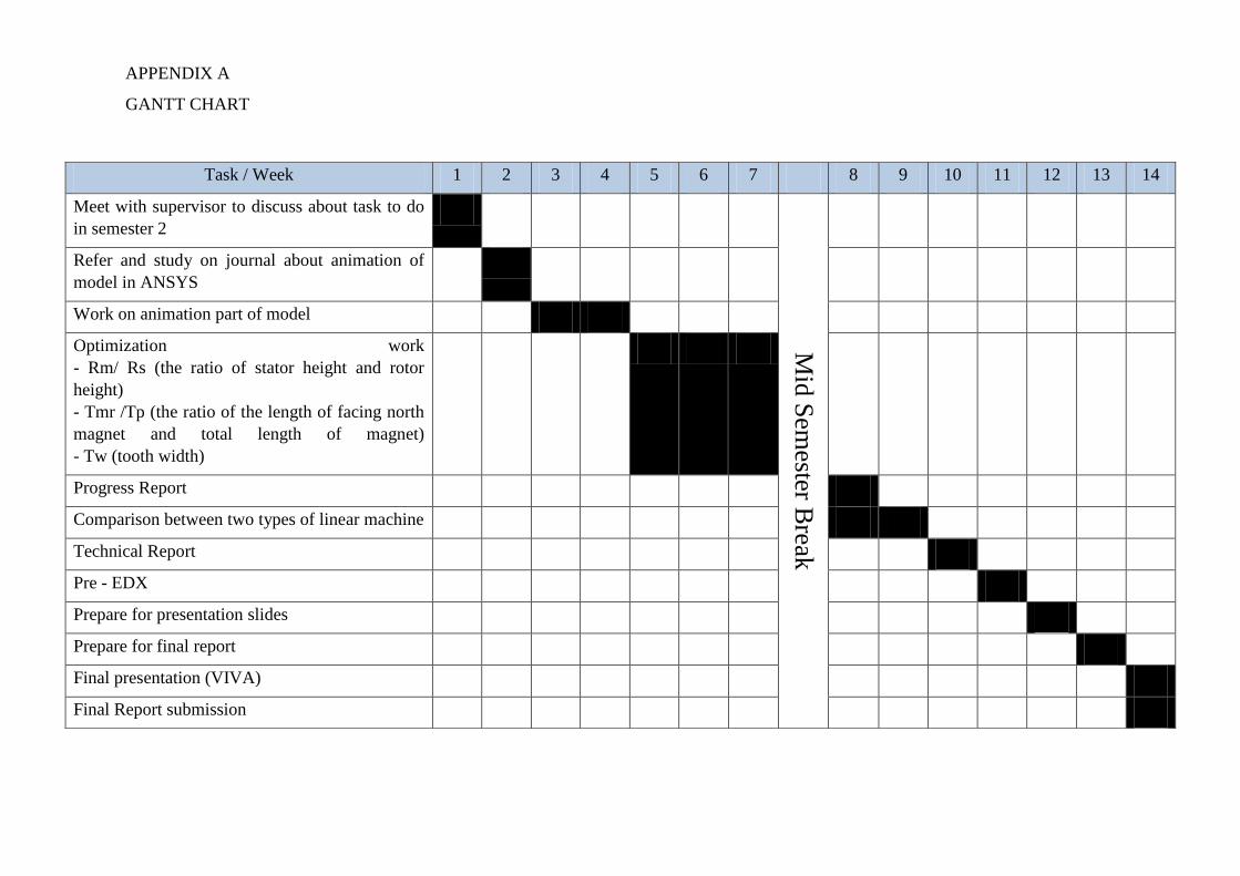
Task / Week 1 2 3 4 5 6 7 8 9 10 11 12 13 14
Meet with supervisor to discuss about task to do
in semester 2
Mid
Sem
ester Break
Refer and study on journal about animation of
model in ANSYS
Work on animation part of model
Optimization work
- Rm/ Rs (the ratio of stator height and rotor
height)
- Tmr /Tp (the ratio of the length of facing north
magnet and total length of magnet)
- Tw (tooth width)
Progress Report
Comparison between two types of linear machine
Technical Report
Pre - EDX
Prepare for presentation slides
Prepare for final report
Final presentation (VIVA)
Final Report submission
Recommended