MODERN TECHNOLOGY FOR EVERYONE
WEB BASED
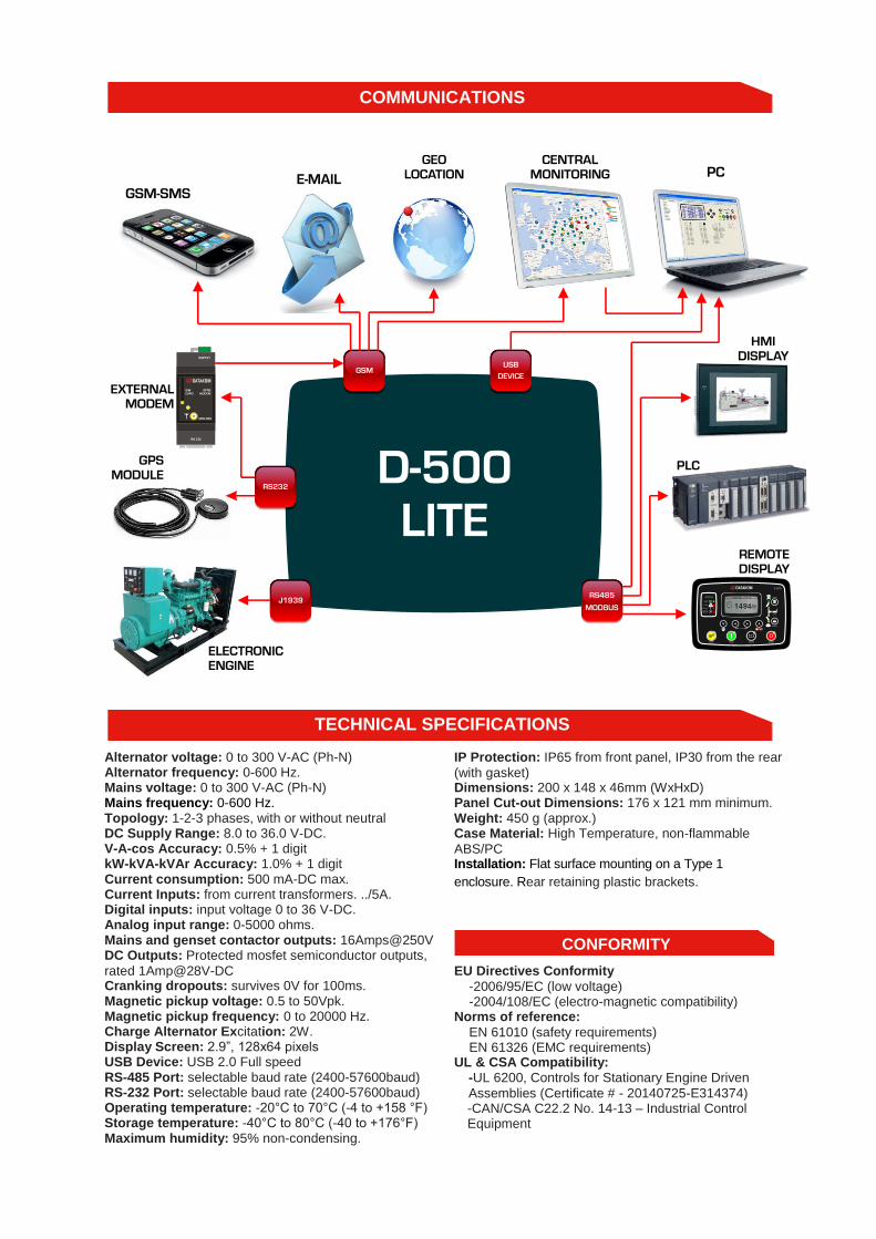
D-500LITE The D-500 is a cost effective genset controller ready for BMS integration and internet monitoring
• 4-band GPRS modem (optional) • USB Device • RS-485 (2400-57600baud) • RS-232 (2400-57600baud) • J1939-CANBUS • Geo-locating through GSM • GPS support (RS-232) • Internet Central Monitoring • SMS message sending • E-mail sending • Free PC software: Rainbow Plus • Modbus RTU
• AMF unit • ATS unit • Remote start controller • Manual start controller • Engine controller • Remote display panel • Harmonic analysis of V & I
• 3 ph 4 w, star & delta • 3 ph 3 w, 2 CTs • 2 ph 3 w • 1 phase 2 wires
• Diesel and gas genset support • 400Hz operation support • 400 event logs, full snapshot • All parameters front panel editable • 3 level configuration password • 128x64 graphical LCD display • Downloadable languages • Waveform display of V & I • Harmonic analysis of V & I • 16Amp MCB & GCB outputs • 8 configurable digital inputs • Inputs expandable to 40 • 6 configurable digital outputs • Outputs expandable to 38 • 3 configurable analog inputs • Both CANBUS-J1939 & MPU • 3 configurable service alarms • Multiple automatic exerciser • Weekly operation schedule • Dual mutual standby with equal aging of gensets • Manual “speed fine adjust” on selected ECUs • Automatic fuel pump control • Disable protections feature • Excess power protection • Reverse power protection • Overload IDMT protection • Load shedding, dummy load • Multiple load management • Current unbalance protection • Voltage unbalance protection
• Fuel filling & fuel theft alarms • Battery back-up real time clock • Idle speed control • Battery charge run enabled • Combat mode support • Multiple nominal conditions • Contactor & MCB drive • 4 quadrant genset power counters • Mains power counters • Fuel filling counter • Fuel consumption counter • Modem diagnostics display • Configurable through USB, RS-485 and GPRS • Free configuration program • Allows SMS controls • Ready for central monitoring • Mobile genset support • Automatic GSM geo-location • GPS connectivity (RS232) • Easy USB firmware upgrade • IP65 rating with standard gasket
• Mains & genset PN/PP voltages • Mains & genset frequency • Mains & genset phase currents • Mains & genset neutral currents • Mains & genset, phase & total, kW, kVA, kVAr, pf • Engine speed • Battery voltage
D 500
WARNING
SERVICEREQUEST
ALARM
PGM
AUTO STOPTEST RUN
MAINS
GENSET
LOAD
A
STATUS
FEATURES
COMMUNICATIONS
MEASUREMENTS
FUNCTIONALITIES
TOPOLOGIES
USB ho
Alternator voltage: 0 to 300 V-AC (Ph-N) Alternator frequency: 0-600 Hz. Mains voltage: 0 to 300 V-AC (Ph-N) Mains frequency: 0-600 Hz. Topology: 1-2-3 phases, with or without neutral DC Supply Range: 8.0 to 36.0 V-DC. V-A-cos Accuracy: 0.5% + 1 digit kW-kVA-kVAr Accuracy: 1.0% + 1 digit Current consumption: 500 mA-DC max. Current Inputs: from current transformers. ../5A. Digital inputs: input voltage 0 to 36 V-DC. Analog input range: 0-5000 ohms. Mains and genset contactor outputs: 16Amps@250V DC Outputs: Protected mosfet semiconductor outputs,
rated 1Amp@28V-DC Cranking dropouts: survives 0V for 100ms. Magnetic pickup voltage: 0.5 to 50Vpk. Magnetic pickup frequency: 0 to 20000 Hz. Charge Alternator Excitation: 2W. Display Screen: 2.9”, 128x64 pixels USB Device: USB 2.0 Full speed RS-485 Port: selectable baud rate (2400-57600baud) RS-232 Port: selectable baud rate (2400-57600baud) Operating temperature: -20°C to 70°C (-4 to +158 °F) Storage temperature: -40°C to 80°C (-40 to +176°F) Maximum humidity: 95% non-condensing.
IP Protection: IP65 from front panel, IP30 from the rear
(with gasket) Dimensions: 200 x 148 x 46mm (WxHxD) Panel Cut-out Dimensions: 176 x 121 mm minimum. Weight: 450 g (approx.) Case Material: High Temperature, non-flammable
ABS/PC Installation: Flat surface mounting on a Type 1
enclosure. Rear retaining plastic brackets.
EU Directives Conformity
-2006/95/EC (low voltage) -2004/108/EC (electro-magnetic compatibility) Norms of reference:
EN 61010 (safety requirements) EN 61326 (EMC requirements) UL & CSA Compatibility:
-UL 6200, Controls for Stationary Engine Driven
Assemblies (Certificate # - 20140725-E314374) -CAN/CSA C22.2 No. 14-13 – Industrial Control Equipment
COMMUNICATIONS
TECHNICAL SPECIFICATIONS
CONFORMITY
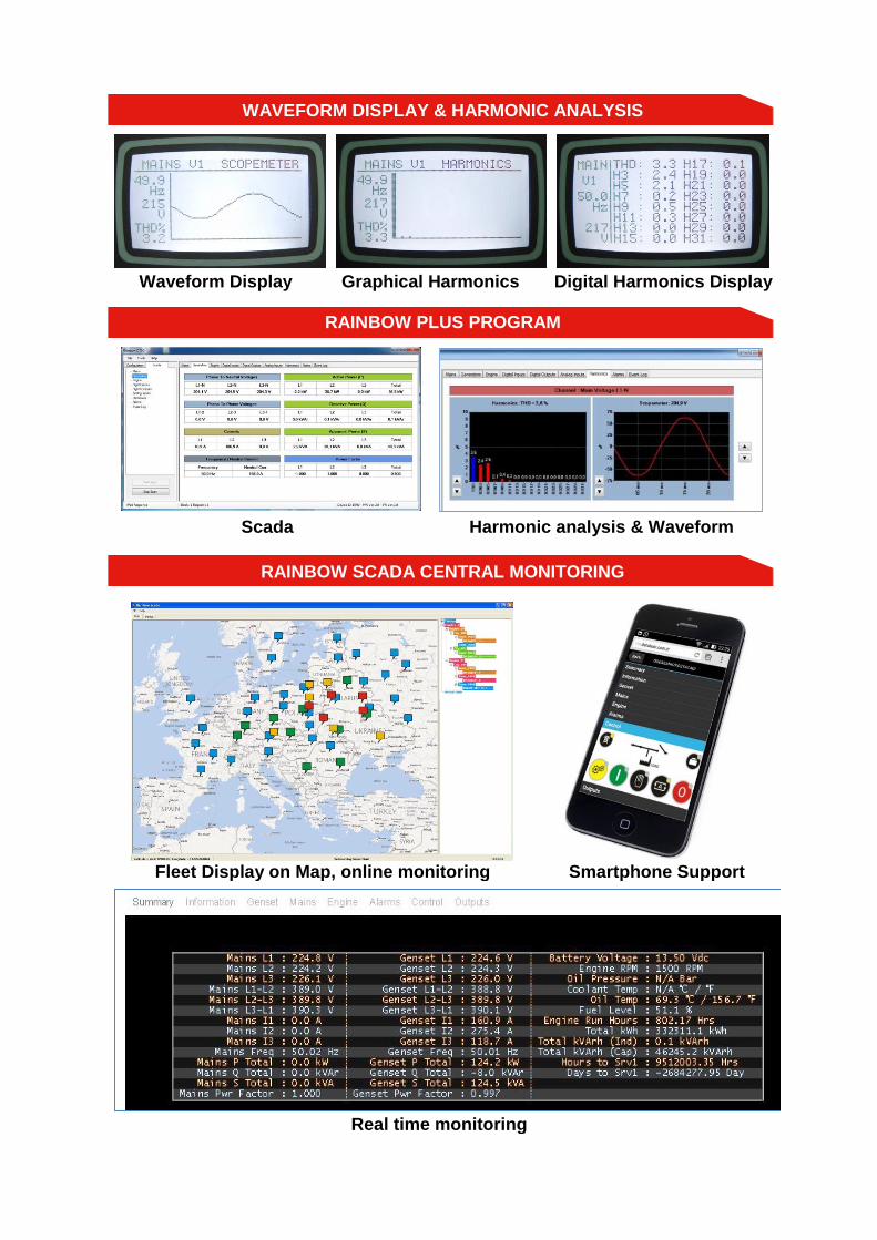
Waveform Display Graphical Harmonics Digital Harmonics Display o
O Scada Harmonic analysis & Waveform
Fleet Display on Map, online monitoring
Smartphone Support
Real time monitoring
RAINBOW PLUS PROGRAM
RAINBOW SCADA CENTRAL MONITORING
WAVEFORM DISPLAY & HARMONIC ANALYSIS
64
63
67
65
66
68
69
70
71
72
3+
3-
I I
MN
-N
MN
-L3
MN
-L2
MN
-L1
MN
-C
RS-232
51
52
53
54
55
56
57
58
62
61
60
59
21 3 4 5 6 7 8 9 10
11
12
13
14
15
16
17
18
19
20
21
22
23
24
25
26
G-N
G-L
3
G-L
2
G-L
1
G-C
I1
+
1-
2+
2-
I I I
BA
T +
BA
T -
OU
T 1
OU
T 2
OU
T 3
OU
T 4
CH
G
IN 1
IN 2
IN 3
IN 4
IN 5
IN 6
IN 7
IN 8
SG
ND
SN
D 1
SN
D 2
SN
D 3
PG
ND
48
5-B
48
5-A
MP
U+
MP
U-
/ P
GN
D
CA
NH
CA
NL
SIMCARD
GSMANTENNA USB-DEVICE
I/OEXTENSION
8 to 36Vdc, 500mA max
!300Vac, 0-600 Hz
0.2 to 6.0 Aac
MAINSL1
L2
L3
N
LOADL3 N
US
EMC
US
E
US
E
FU
SE
FU
SE
FU
SE
L1
L2
L3
N
ALTERNATORL1 L2
GC
BA
TT
ER
Y 1
2/2
4V
StarterMotor
Fuse Cra
nk
S
To BMS
*2
Ch
arg
e A
ltern
ato
rD
+ /
WL Lo
w O
il P
ressu
re
Hig
h T
em
p
Em
erg
ency S
top
Lo
w C
oola
nt
Level
Spa
re I
np
ut
1
Fo
rce O
FF
Mo
de
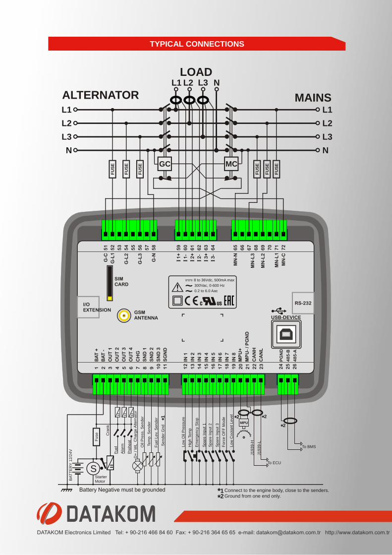
Connect to the engine body, close to the senders.
*2Ground from one end only.
Spa
re I
np
ut
2
Spa
re I
np
ut
3
Sen
der
Gn
d
*1
Te
mp. S
end
er
Oil
Pre
ss.
Se
nde
r
Fu
el Le
v. S
en
de
r
*1
J1
93
9-H
J1
93
9-L
*2
To ECU
MPU*2
F F F
Fuel
Ala
rm
Pre
hea
t
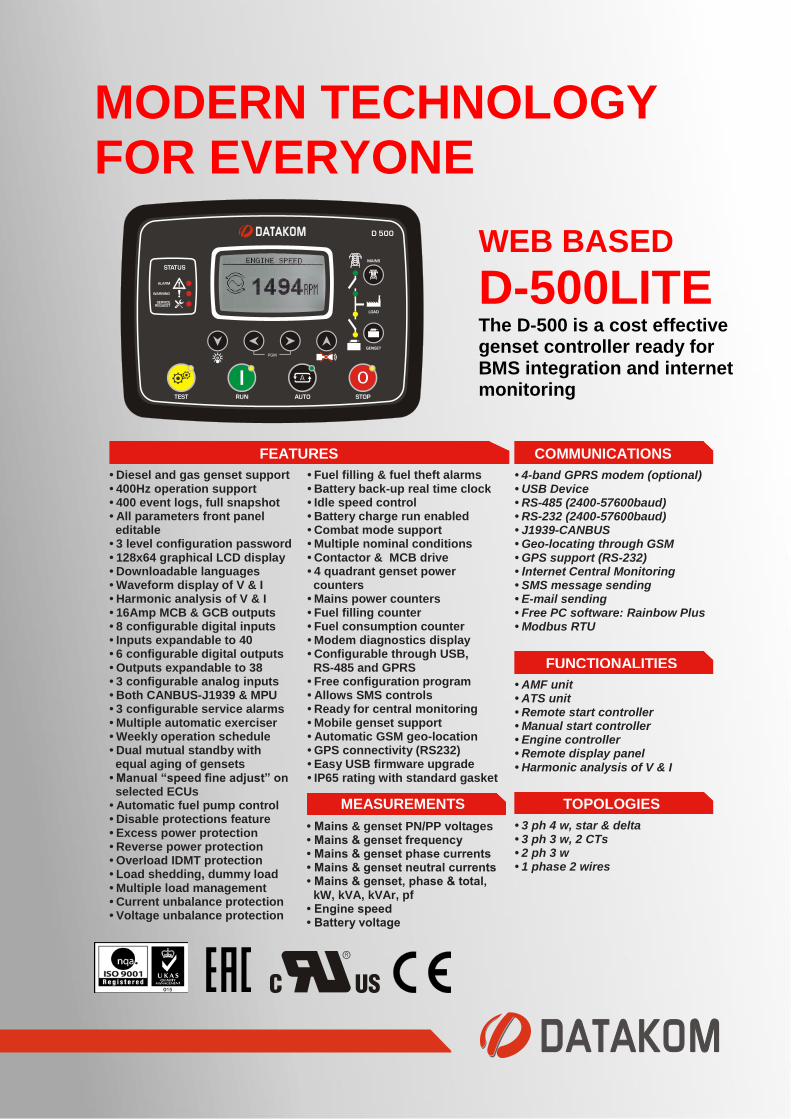
TYPICAL CONNECTIONS
Recommended