Morphing wing application on Hydra Technologies UASS4
Segui, M, SugarGabor, O, Koreanschi, A and Botez, RM
http://dx.doi.org/10.2316/P.2016.848048
Title Morphing wing application on Hydra Technologies UASS4
Authors Segui, M, SugarGabor, O, Koreanschi, A and Botez, RM
Type Conference or Workshop Item
URL This version is available at: http://usir.salford.ac.uk/43737/
Published Date 2017
USIR is a digital collection of the research output of the University of Salford. Where copyright permits, full text material held in the repository is made freely available online and can be read, downloaded and copied for noncommercial private study or research purposes. Please check the manuscript for any further copyright restrictions.
For more information, including our policy and submission procedure, pleasecontact the Repository Team at: [email protected].
MORPHING WING APPLICATION ON HYDRA TECHNOLOGIES UAS-S4
Marine Segui1, Oliviu Sugar Gabor2 Andreea Koreanschi
3 and Ruxandra Mihaela Botez4
ETS, Laboratory of Active Controls, Avionics and AeroServoElasticity LARCASE
1100 Notre Dame West, Montreal, Quebec, Canada, H3C-1K3
ABSTRACT
This paper presents the aerodynamic results of a
morphing wing study performed on the UAS S4 Éhecatl
from Hydra Technologies. Only the cruise phase of the
aircraft was considered (constant altitude and constant
speed). The difference, from an aerodynamic point of
view, between the morphing wing and the original wing
was emphasized by computing and comparing their
longitudinal aerodynamic coefficients (drag and lift). The
computation of the aerodynamic characteristics was done
using tornado with the Vortex Lattice Method.
KEY WORDS
Unmanned Aerial System, aerodynamic optimization,
Morphing Wing.
1. Introduction
The globalization has made that people travel increasingly
by air transportation. Meanwhile, some environmental
conferences are organized against the global warming to
regulate carbon dioxide (CO2) emissions as result of new
society consumption. In the aeronautic industry, a means
to reduce carbon dioxide emission have to be finding.
Since 1998, Air Force Research Laboratory (AFRL),
FlexSys Inc and NASA’s test team are working together
to reduce fuel cost. They suggest to modify flight control
surfaces on existing aircraft such as flaps in Adaptive
Compliant Trailing Edge (ACTE) project [1]. Based on
this idea, some principles were developed to improve
carbon dioxide emission, above all, a special material [2]
or a smart wing project [3, 4] nowadays called “morphing
wing”.
In this paper the morphing wing technology
consists in the change of the wing’s airfoil shape during
flight [5]. This concept, showed improved the
performances of the wing’s airfoil through optimization of
the original airfoil; the optimization was carried at
different velocities, angles of attack and Reynolds
numbers. The drag was reduced, while the lift was
increase or kept constant (depend on case) at all flight
phases [6-9].
The aerodynamic study here presented consists in
applying the morphing wing’s airfoil concept on a part of
span wing, and ensuring the improvement of the wing’s
aerodynamic performances.
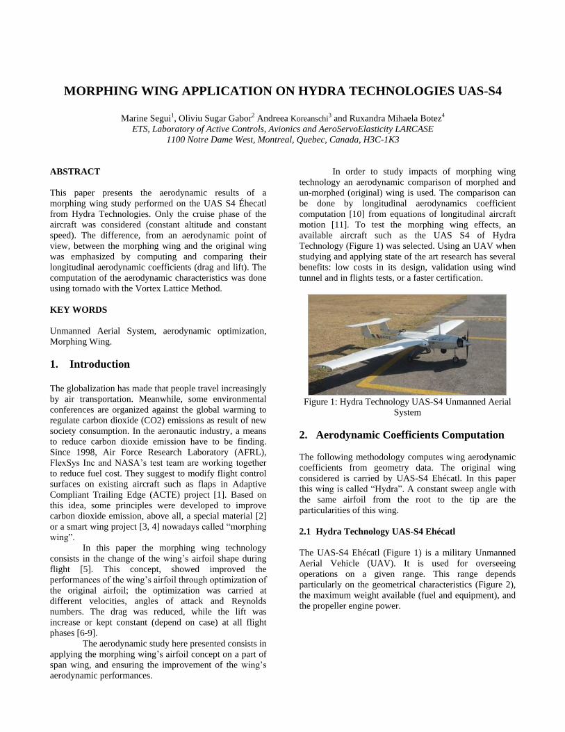
In order to study impacts of morphing wing
technology an aerodynamic comparison of morphed and
un-morphed (original) wing is used. The comparison can
be done by longitudinal aerodynamics coefficient
computation [10] from equations of longitudinal aircraft
motion [11]. To test the morphing wing effects, an
available aircraft such as the UAS S4 of Hydra
Technology (Figure 1) was selected. Using an UAV when
studying and applying state of the art research has several
benefits: low costs in its design, validation using wind
tunnel and in flights tests, or a faster certification.
Figure 1: Hydra Technology UAS-S4 Unmanned Aerial
System
2. Aerodynamic Coefficients Computation
The following methodology computes wing aerodynamic
coefficients from geometry data. The original wing
considered is carried by UAS-S4 Ehécatl. In this paper
this wing is called “Hydra”. A constant sweep angle with
the same airfoil from the root to the tip are the
particularities of this wing.
2.1 Hydra Technology UAS-S4 Ehécatl
The UAS-S4 Ehécatl (Figure 1) is a military Unmanned
Aerial Vehicle (UAV). It is used for overseeing
operations on a given range. This range depends
particularly on the geometrical characteristics (Figure 2),
the maximum weight available (fuel and equipment), and
the propeller engine power.
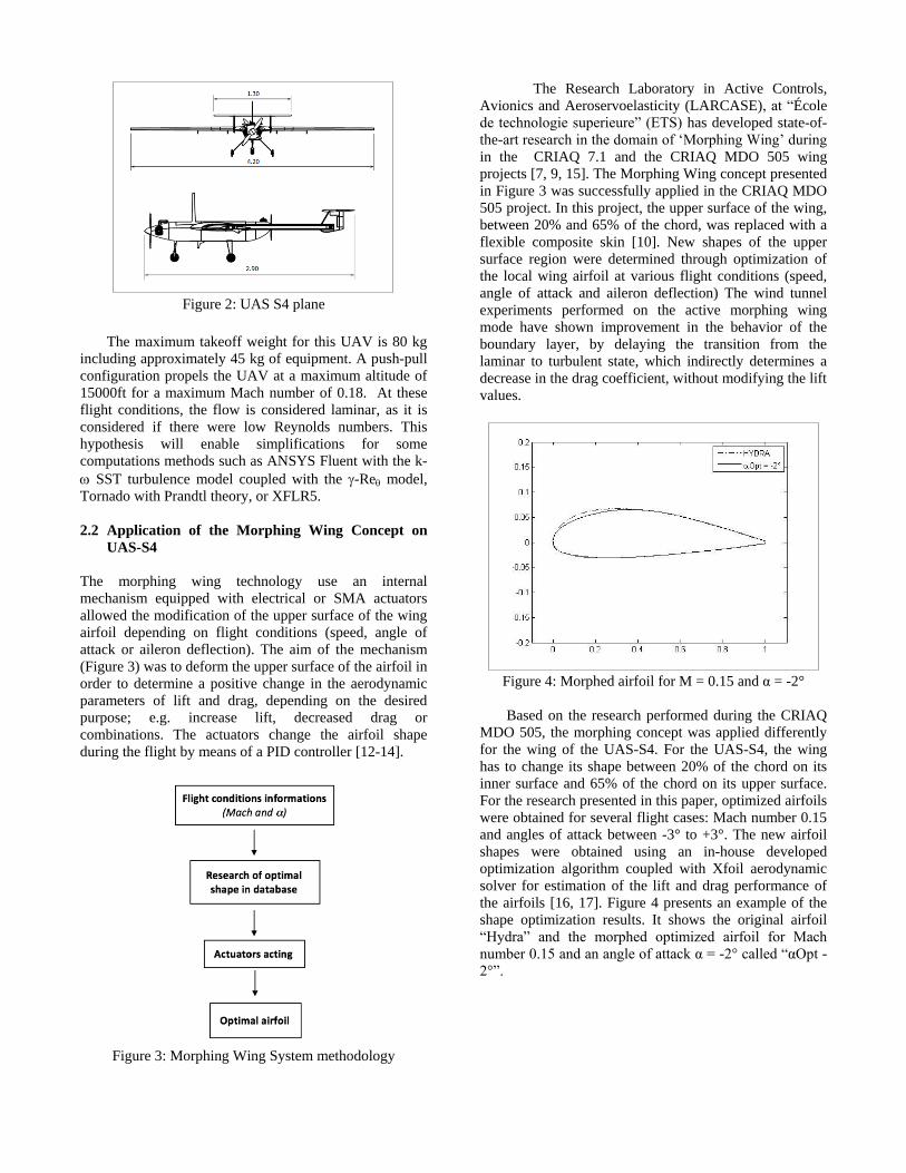
Figure 2: UAS S4 plane
The maximum takeoff weight for this UAV is 80 kg
including approximately 45 kg of equipment. A push-pull
configuration propels the UAV at a maximum altitude of
15000ft for a maximum Mach number of 0.18. At these
flight conditions, the flow is considered laminar, as it is
considered if there were low Reynolds numbers. This
hypothesis will enable simplifications for some
computations methods such as ANSYS Fluent with the k-
SST turbulence model coupled with the -Re model,
Tornado with Prandtl theory, or XFLR5.
2.2 Application of the Morphing Wing Concept on
UAS-S4
The morphing wing technology use an internal
mechanism equipped with electrical or SMA actuators
allowed the modification of the upper surface of the wing
airfoil depending on flight conditions (speed, angle of
attack or aileron deflection). The aim of the mechanism
(Figure 3) was to deform the upper surface of the airfoil in
order to determine a positive change in the aerodynamic
parameters of lift and drag, depending on the desired
purpose; e.g. increase lift, decreased drag or
combinations. The actuators change the airfoil shape
during the flight by means of a PID controller [12-14].
Figure 3: Morphing Wing System methodology
The Research Laboratory in Active Controls,
Avionics and Aeroservoelasticity (LARCASE), at “École
de technologie superieure” (ETS) has developed state-of-
the-art research in the domain of ‘Morphing Wing’ during
in the CRIAQ 7.1 and the CRIAQ MDO 505 wing
projects [7, 9, 15]. The Morphing Wing concept presented
in Figure 3 was successfully applied in the CRIAQ MDO
505 project. In this project, the upper surface of the wing,
between 20% and 65% of the chord, was replaced with a
flexible composite skin [10]. New shapes of the upper
surface region were determined through optimization of
the local wing airfoil at various flight conditions (speed,
angle of attack and aileron deflection) The wind tunnel
experiments performed on the active morphing wing
mode have shown improvement in the behavior of the
boundary layer, by delaying the transition from the
laminar to turbulent state, which indirectly determines a
decrease in the drag coefficient, without modifying the lift
values.
Figure 4: Morphed airfoil for M = 0.15 and α = -2°
Based on the research performed during the CRIAQ
MDO 505, the morphing concept was applied differently
for the wing of the UAS-S4. For the UAS-S4, the wing
has to change its shape between 20% of the chord on its
inner surface and 65% of the chord on its upper surface.
For the research presented in this paper, optimized airfoils
were obtained for several flight cases: Mach number 0.15
and angles of attack between -3° to +3°. The new airfoil
shapes were obtained using an in-house developed
optimization algorithm coupled with Xfoil aerodynamic
solver for estimation of the lift and drag performance of
the airfoils [16, 17]. Figure 4 presents an example of the
shape optimization results. It shows the original airfoil
“Hydra” and the morphed optimized airfoil for Mach
number 0.15 and an angle of attack α = -2° called “αOpt -
2°”.
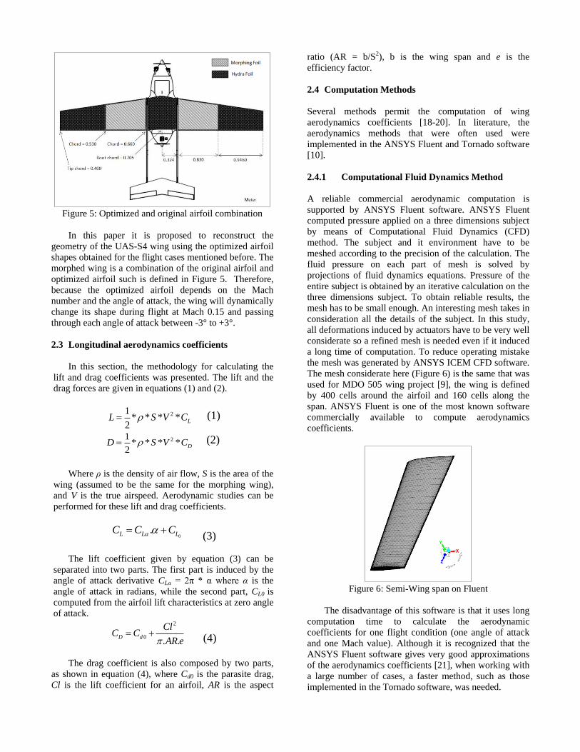
Figure 5: Optimized and original airfoil combination
In this paper it is proposed to reconstruct the
geometry of the UAS-S4 wing using the optimized airfoil
shapes obtained for the flight cases mentioned before. The
morphed wing is a combination of the original airfoil and
optimized airfoil such is defined in Figure 5. Therefore,
because the optimized airfoil depends on the Mach
number and the angle of attack, the wing will dynamically
change its shape during flight at Mach 0.15 and passing
through each angle of attack between -3° to +3°.
2.3 Longitudinal aerodynamics coefficients
In this section, the methodology for calculating the
lift and drag coefficients was presented. The lift and the
drag forces are given in equations (1) and (2).
21* * * *
2LL S V C (1)
21* * * *
2DD S V C
(2)
Where ρ is the density of air flow, S is the area of the
wing (assumed to be the same for the morphing wing),
and V is the true airspeed. Aerodynamic studies can be
performed for these lift and drag coefficients.
0.L L LC C C
(3)
The lift coefficient given by equation (3) can be
separated into two parts. The first part is induced by the
angle of attack derivative CLα = 2π * α where α is the
angle of attack in radians, while the second part, CL0 is
computed from the airfoil lift characteristics at zero angle
of attack. 2
0. .
D d
ClC C
AR e
(4)
The drag coefficient is also composed by two parts,
as shown in equation (4), where Cd0 is the parasite drag,
Cl is the lift coefficient for an airfoil, AR is the aspect
ratio (AR = b/S2), b is the wing span and e is the
efficiency factor.
2.4 Computation Methods
Several methods permit the computation of wing
aerodynamics coefficients [18-20]. In literature, the
aerodynamics methods that were often used were
implemented in the ANSYS Fluent and Tornado software
[10].
2.4.1 Computational Fluid Dynamics Method
A reliable commercial aerodynamic computation is
supported by ANSYS Fluent software. ANSYS Fluent
computed pressure applied on a three dimensions subject
by means of Computational Fluid Dynamics (CFD)
method. The subject and it environment have to be
meshed according to the precision of the calculation. The
fluid pressure on each part of mesh is solved by
projections of fluid dynamics equations. Pressure of the
entire subject is obtained by an iterative calculation on the
three dimensions subject. To obtain reliable results, the
mesh has to be small enough. An interesting mesh takes in
consideration all the details of the subject. In this study,
all deformations induced by actuators have to be very well
considerate so a refined mesh is needed even if it induced
a long time of computation. To reduce operating mistake
the mesh was generated by ANSYS ICEM CFD software.
The mesh considerate here (Figure 6) is the same that was
used for MDO 505 wing project [9], the wing is defined
by 400 cells around the airfoil and 160 cells along the
span. ANSYS Fluent is one of the most known software
commercially available to compute aerodynamics
coefficients.
Figure 6: Semi-Wing span on Fluent
The disadvantage of this software is that it uses long
computation time to calculate the aerodynamic
coefficients for one flight condition (one angle of attack
and one Mach value). Although it is recognized that the
ANSYS Fluent software gives very good approximations
of the aerodynamics coefficients [21], when working with
a large number of cases, a faster method, such as those
implemented in the Tornado software, was needed.
2.4.2 Vortex Lattice Method
The Vortex Lattice Method (VLM) is a method dedicated
to compute aerodynamic coefficients of wings. In 1966, in
the early years of these method, only thin wings were
considered in the VLM [22] but that hypothesis was
excessively large. Then in 1993, the VLM was improved
in order to consider more precisely the components of the
wing, with the nonlinear motions of flaps [23] for
example. Nowadays, small details of the wing geometry
need to be taken into account in order to improve the
quality of the computational results. The VLM method
that was used in this paper, was implemented in the
Tornado platform, run by Matlab software [24].
Therefore, the wing is entirely modelled according to the
three dimensions (3D) panels method, the geometry of the
wing considered by the method can be showing like
Figure 7 (two dimensions), and an airfoil is associated to
this wing, which represent the third dimension. If the
wing is not carried by the same airfoil from the root to the
tip (original airfoil such as Hydra), Tornado platform
allow to “cut” the two dimensions of the wing in the span
to create wing sections, called “semi-wing”. In this case, a
different airfoil can be assigned to each “semi-wing”,
actually, it’s the procedure when the morphing wing is
computed. For the UAS-S4, three symmetrical semi wing
were create following Figure 5, original airfoil is assigned
around the root and around the tip sections of the wing
and Optimized airfoil is assigned in the middle part.
The flow was considered to be described by the Mach
number (altitude and speed parameters).
Figure 7: Wing definition in the Tornado software
Although Tornado software is very interesting from the
point of view of the rapidity of the computation time
(around 10 seconds per airfoil for 13 angles of attack),
this method needed many approximations of the wing
modeling. To ensure Tornado software make reliable
approximations, a study was made to confirm this
method. In this respect, a comparison was made between
aerodynamic coefficients obtained by Tornado software
and ANSYS Fluent software (Figure 8 and Figure 9). The
wing considered carried by Hydra airfoil from the root to
the tip.
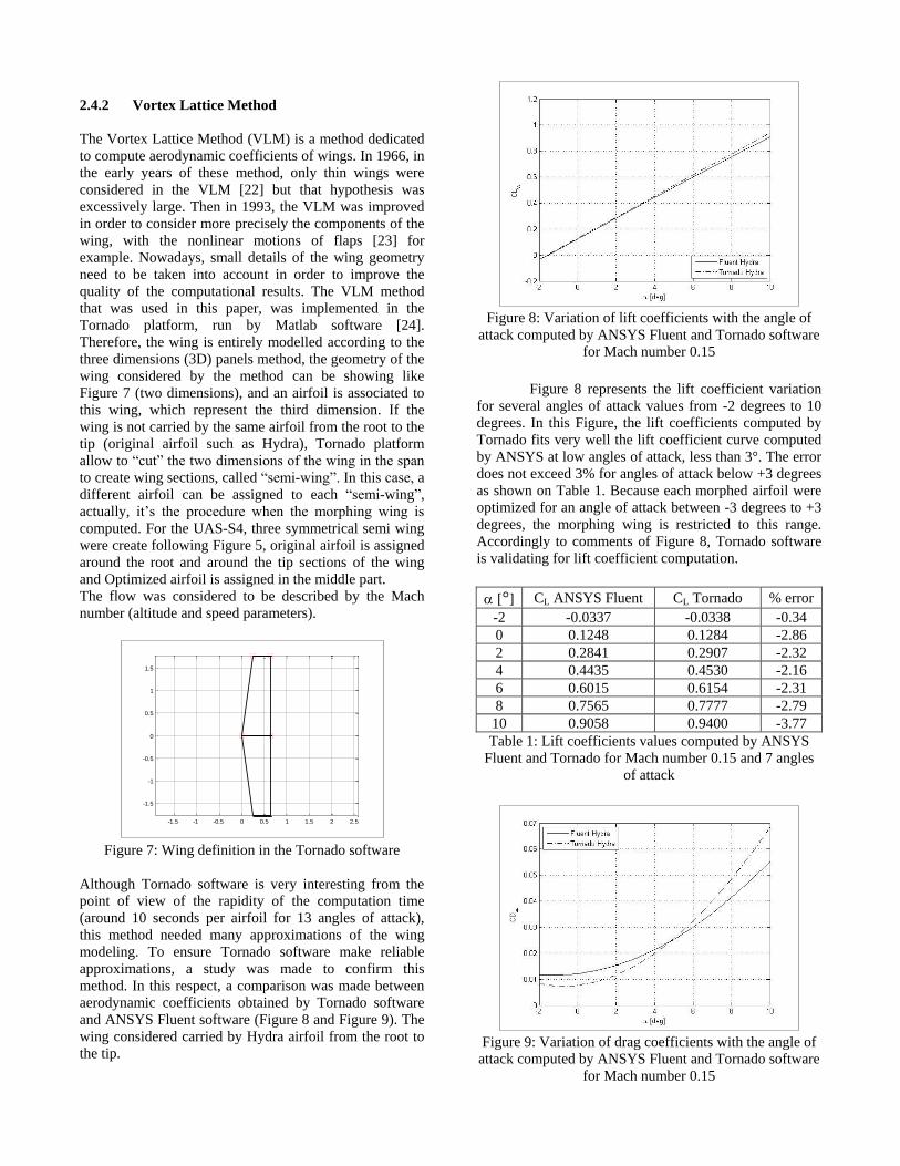
Figure 8: Variation of lift coefficients with the angle of
attack computed by ANSYS Fluent and Tornado software
for Mach number 0.15
Figure 8 represents the lift coefficient variation
for several angles of attack values from -2 degrees to 10
degrees. In this Figure, the lift coefficients computed by
Tornado fits very well the lift coefficient curve computed
by ANSYS at low angles of attack, less than 3°. The error
does not exceed 3% for angles of attack below +3 degrees
as shown on Table 1. Because each morphed airfoil were
optimized for an angle of attack between -3 degrees to +3
degrees, the morphing wing is restricted to this range.
Accordingly to comments of Figure 8, Tornado software
is validating for lift coefficient computation.
[°] CL ANSYS Fluent CL Tornado % error
-2 -0.0337 -0.0338 -0.34
0 0.1248 0.1284 -2.86
2 0.2841 0.2907 -2.32
4 0.4435 0.4530 -2.16
6 0.6015 0.6154 -2.31
8 0.7565 0.7777 -2.79
10 0.9058 0.9400 -3.77
Table 1: Lift coefficients values computed by ANSYS
Fluent and Tornado for Mach number 0.15 and 7 angles
of attack
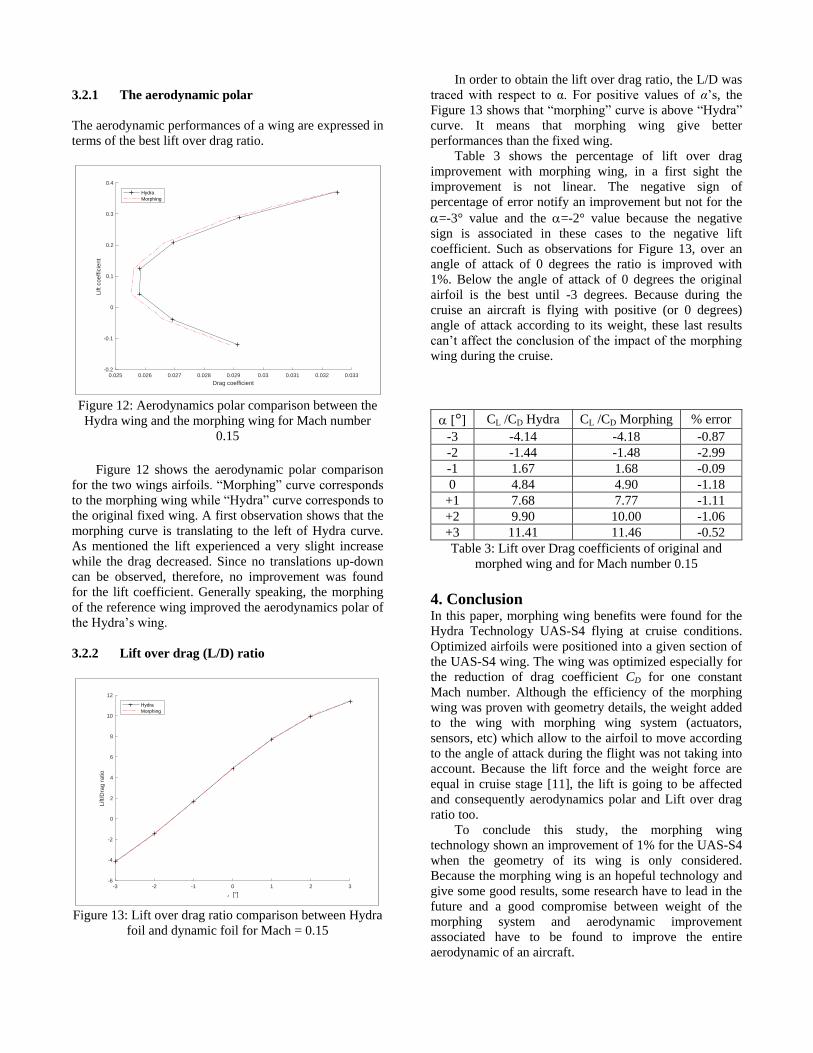
Figure 9: Variation of drag coefficients with the angle of
attack computed by ANSYS Fluent and Tornado software
for Mach number 0.15
-1.5 -1 -0.5 0 0.5 1 1.5 2 2.5
-1.5
-1
-0.5
0
0.5
1
1.5
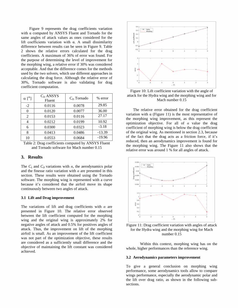
Figure 9 represents the drag coefficients variation
with α computed by ANSYS Fluent and Tornado for the
same angles of attack values as ones considered for the
lift coefficients variation with α. A small dissimilarity
difference between results can be seen in Figure 9. Table
2 shows the relative errors calculated for the drag
coefficients. A maximum of 36% of error was found. For
the purpose of determining the level of improvement for
the morphing wing, a relative error if 30% was considered
acceptable. And that the difference comes for the methods
used by the two solvers, which use different approaches in
calculating the drag force. Although the relative error of
30%, Tornado software is also validating for drag
coefficient computation.
[°] CD ANSYS
Fluent CD Tornado % error
-2 0.0116 0.0078 29.85
0 0.0120 0.0077 36.00
2 0.0153 0.0116 27.17
4 0.0212 0.0199 10.92
6 0.0300 0.0323 -3.18
8 0.0413 0.0486 -13.39
10 0.0553 0.0684 -19.96
Table 2: Drag coefficients computed by ANSYS Fluent
and Tornado software for Mach number 0.15
3. Results
The CL and CD variations with α, the aerodynamics polar
and the finesse ratio variation with α are presented in this
section. These results were obtained using the Tornado
software. The morphing wing is represented with a curve
because it’s considered that the airfoil move its shape
continuously between two angles of attack.
3.1 Lift and Drag improvement
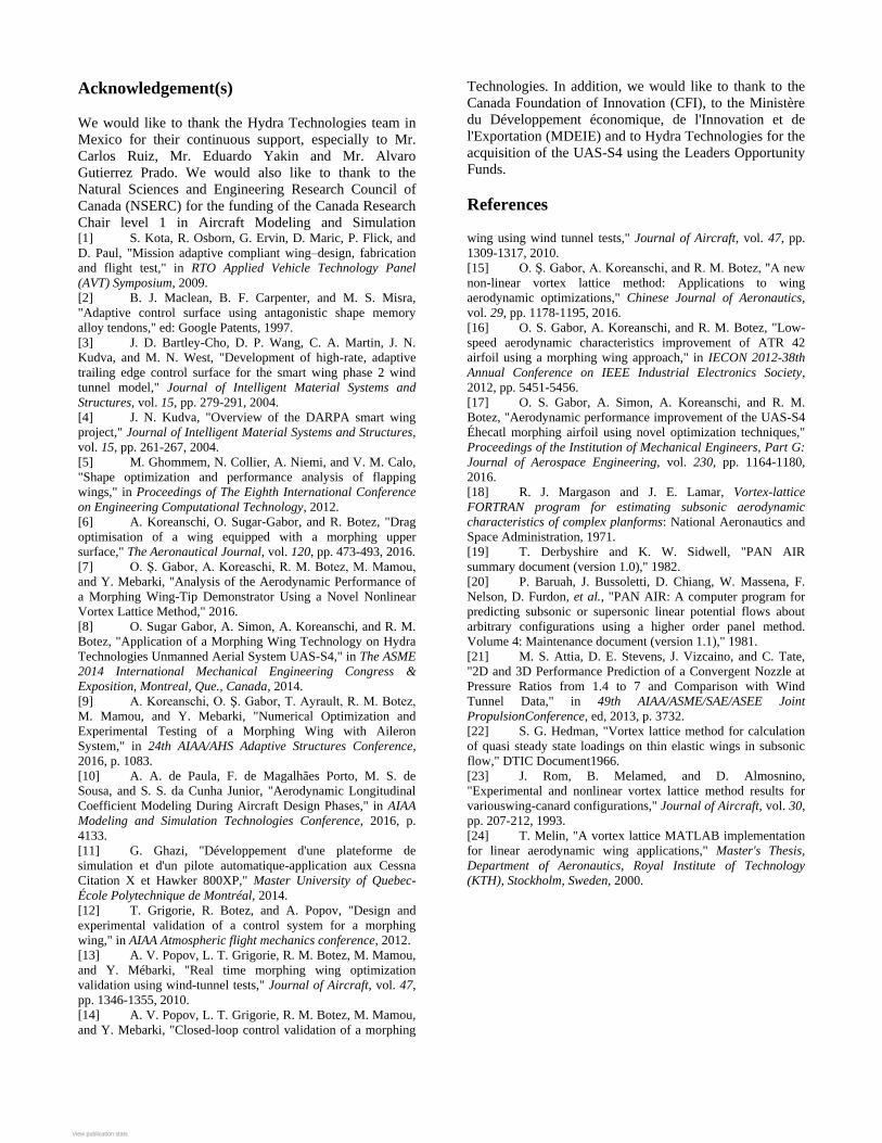
The variations of lift and drag coefficients with α are
presented in Figure 10. The relative error observed
between the lift coefficient computed for the morphing
wing and the original wing is approximately 2% for
negative angles of attack and 0.5% for positives angles of
attack. Thus, the improvement on lift of the morphing
airfoil is small. As an improvement of the lift coefficient
was not part of the optimization objective, these results
are considered as a sufficiently small difference and the
objective of maintaining the lift constant was considered
achieved.
Figure 10: Lift coefficient variation with the angle of
attack for the Hydra wing and the morphing wing and for
Mach number 0.15
The relative error obtained for the drag coefficient
variation with α (Figure 11) is the most representative of
the morphing wing improvement, as this represent the
optimization objective. For all of α value the drag
coefficient of morphing wing is below the drag coefficient
of the original wing. As mentioned in section 2.3, because
of the fact that the drag acts as a friction force, if it’s
reduced, then an aerodynamics improvement is found for
the morphing wing. The Figure 11 also shows that the
relative error was around 1 % for all angles of attack.
Figure 11: Drag coefficient variation with angles of attack
for the Hydra wing and the morphing wing for Mach
number 0.15
Within this context, morphing wing has on the
whole, higher performances than the reference wing.
3.2 Aerodynamics parameters improvement
To give a general conclusion on morphing wing
performance, some aerodynamics tools allow to compare
wings performance, especially the aerodynamic polar and
the lift over drag ratio, as shown in the following sub-
sections.
-3 -2 -1 0 1 2 3-0.2
-0.1
0
0.1
0.2
0.3
0.4
Lift co
effic
ien
t
Hydra
Morphing
-3 -2 -1 0 1 2 3
, [°]
-2
-1
0
1
2
err
or
-3 -2 -1 0 1 2 30.024
0.026
0.028
0.03
0.032
0.034
Dra
g c
oeff
icie
nt
Hydra
Morphing
-3 -2 -1 0 1 2 3
, [°]
0
0.2
0.4
0.6
0.8
1
1.2
err
or
3.2.1 The aerodynamic polar
The aerodynamic performances of a wing are expressed in
terms of the best lift over drag ratio.
Figure 12: Aerodynamics polar comparison between the
Hydra wing and the morphing wing for Mach number
0.15
Figure 12 shows the aerodynamic polar comparison
for the two wings airfoils. “Morphing” curve corresponds
to the morphing wing while “Hydra” curve corresponds to
the original fixed wing. A first observation shows that the
morphing curve is translating to the left of Hydra curve.
As mentioned the lift experienced a very slight increase
while the drag decreased. Since no translations up-down
can be observed, therefore, no improvement was found
for the lift coefficient. Generally speaking, the morphing
of the reference wing improved the aerodynamics polar of
the Hydra’s wing.
3.2.2 Lift over drag (L/D) ratio
Figure 13: Lift over drag ratio comparison between Hydra
foil and dynamic foil for Mach = 0.15
In order to obtain the lift over drag ratio, the L/D was
traced with respect to α. For positive values of α’s, the
Figure 13 shows that “morphing” curve is above “Hydra”
curve. It means that morphing wing give better
performances than the fixed wing.
Table 3 shows the percentage of lift over drag
improvement with morphing wing, in a first sight the
improvement is not linear. The negative sign of
percentage of error notify an improvement but not for the
=-3° value and the =-2° value because the negative
sign is associated in these cases to the negative lift
coefficient. Such as observations for Figure 13, over an
angle of attack of 0 degrees the ratio is improved with
1%. Below the angle of attack of 0 degrees the original
airfoil is the best until -3 degrees. Because during the
cruise an aircraft is flying with positive (or 0 degrees)
angle of attack according to its weight, these last results
can’t affect the conclusion of the impact of the morphing
wing during the cruise.
[°] CL /CD Hydra CL /CD Morphing % error
-3 -4.14 -4.18 -0.87
-2 -1.44 -1.48 -2.99
-1 1.67 1.68 -0.09
0 4.84 4.90 -1.18
+1 7.68 7.77 -1.11
+2 9.90 10.00 -1.06
+3 11.41 11.46 -0.52
Table 3: Lift over Drag coefficients of original and
morphed wing and for Mach number 0.15
4. Conclusion In this paper, morphing wing benefits were found for the
Hydra Technology UAS-S4 flying at cruise conditions.
Optimized airfoils were positioned into a given section of
the UAS-S4 wing. The wing was optimized especially for
the reduction of drag coefficient CD for one constant
Mach number. Although the efficiency of the morphing
wing was proven with geometry details, the weight added
to the wing with morphing wing system (actuators,
sensors, etc) which allow to the airfoil to move according
to the angle of attack during the flight was not taking into
account. Because the lift force and the weight force are
equal in cruise stage [11], the lift is going to be affected
and consequently aerodynamics polar and Lift over drag
ratio too.
To conclude this study, the morphing wing
technology shown an improvement of 1% for the UAS-S4
when the geometry of its wing is only considered.
Because the morphing wing is an hopeful technology and
give some good results, some research have to lead in the
future and a good compromise between weight of the
morphing system and aerodynamic improvement
associated have to be found to improve the entire
aerodynamic of an aircraft.
0.025 0.026 0.027 0.028 0.029 0.03 0.031 0.032 0.033
Drag coefficient
-0.2
-0.1
0
0.1
0.2
0.3
0.4
Lift coe
ffic
ien
t
Hydra
Morphing
-3 -2 -1 0 1 2 3
, [°]
-6
-4
-2
0
2
4
6
8
10
12
Lift/
Dra
g r
atio
Hydra
Morphing
Acknowledgement(s)
We would like to thank the Hydra Technologies team in
Mexico for their continuous support, especially to Mr.
Carlos Ruiz, Mr. Eduardo Yakin and Mr. Alvaro
Gutierrez Prado. We would also like to thank to the
Natural Sciences and Engineering Research Council of
Canada (NSERC) for the funding of the Canada Research
Chair level 1 in Aircraft Modeling and Simulation
Technologies. In addition, we would like to thank to the
Canada Foundation of Innovation (CFI), to the Ministère
du Développement économique, de l'Innovation et de
l'Exportation (MDEIE) and to Hydra Technologies for the
acquisition of the UAS-S4 using the Leaders Opportunity
Funds.
References
[1] S. Kota, R. Osborn, G. Ervin, D. Maric, P. Flick, and
D. Paul, "Mission adaptive compliant wing–design, fabrication
and flight test," in RTO Applied Vehicle Technology Panel
(AVT) Symposium, 2009.
[2] B. J. Maclean, B. F. Carpenter, and M. S. Misra,
"Adaptive control surface using antagonistic shape memory
alloy tendons," ed: Google Patents, 1997.
[3] J. D. Bartley-Cho, D. P. Wang, C. A. Martin, J. N.
Kudva, and M. N. West, "Development of high-rate, adaptive
trailing edge control surface for the smart wing phase 2 wind
tunnel model," Journal of Intelligent Material Systems and
Structures, vol. 15, pp. 279-291, 2004.
[4] J. N. Kudva, "Overview of the DARPA smart wing
project," Journal of Intelligent Material Systems and Structures,
vol. 15, pp. 261-267, 2004.
[5] M. Ghommem, N. Collier, A. Niemi, and V. M. Calo,
"Shape optimization and performance analysis of flapping
wings," in Proceedings of The Eighth International Conference
on Engineering Computational Technology, 2012.
[6] A. Koreanschi, O. Sugar-Gabor, and R. Botez, "Drag
optimisation of a wing equipped with a morphing upper
surface," The Aeronautical Journal, vol. 120, pp. 473-493, 2016.
[7] O. Ş. Gabor, A. Koreaschi, R. M. Botez, M. Mamou,
and Y. Mebarki, "Analysis of the Aerodynamic Performance of
a Morphing Wing-Tip Demonstrator Using a Novel Nonlinear
Vortex Lattice Method," 2016.
[8] O. Sugar Gabor, A. Simon, A. Koreanschi, and R. M.
Botez, "Application of a Morphing Wing Technology on Hydra
Technologies Unmanned Aerial System UAS-S4," in The ASME
2014 International Mechanical Engineering Congress &
Exposition, Montreal, Que., Canada, 2014.
[9] A. Koreanschi, O. Ş. Gabor, T. Ayrault, R. M. Botez,
M. Mamou, and Y. Mebarki, "Numerical Optimization and
Experimental Testing of a Morphing Wing with Aileron
System," in 24th AIAA/AHS Adaptive Structures Conference,
2016, p. 1083.
[10] A. A. de Paula, F. de Magalhães Porto, M. S. de
Sousa, and S. S. da Cunha Junior, "Aerodynamic Longitudinal
Coefficient Modeling During Aircraft Design Phases," in AIAA
Modeling and Simulation Technologies Conference, 2016, p.
4133.
[11] G. Ghazi, "Développement d'une plateforme de
simulation et d'un pilote automatique-application aux Cessna
Citation X et Hawker 800XP," Master University of Quebec-
École Polytechnique de Montréal, 2014.
[12] T. Grigorie, R. Botez, and A. Popov, "Design and
experimental validation of a control system for a morphing
wing," in AIAA Atmospheric flight mechanics conference, 2012.
[13] A. V. Popov, L. T. Grigorie, R. M. Botez, M. Mamou,
and Y. Mébarki, "Real time morphing wing optimization
validation using wind-tunnel tests," Journal of Aircraft, vol. 47,
pp. 1346-1355, 2010.
[14] A. V. Popov, L. T. Grigorie, R. M. Botez, M. Mamou,
and Y. Mebarki, "Closed-loop control validation of a morphing
wing using wind tunnel tests," Journal of Aircraft, vol. 47, pp.
1309-1317, 2010.
[15] O. Ş. Gabor, A. Koreanschi, and R. M. Botez, "A new
non-linear vortex lattice method: Applications to wing
aerodynamic optimizations," Chinese Journal of Aeronautics,
vol. 29, pp. 1178-1195, 2016.
[16] O. S. Gabor, A. Koreanschi, and R. M. Botez, "Low-
speed aerodynamic characteristics improvement of ATR 42
airfoil using a morphing wing approach," in IECON 2012-38th
Annual Conference on IEEE Industrial Electronics Society,
2012, pp. 5451-5456.
[17] O. S. Gabor, A. Simon, A. Koreanschi, and R. M.
Botez, "Aerodynamic performance improvement of the UAS-S4
Éhecatl morphing airfoil using novel optimization techniques,"
Proceedings of the Institution of Mechanical Engineers, Part G:
Journal of Aerospace Engineering, vol. 230, pp. 1164-1180,
2016.
[18] R. J. Margason and J. E. Lamar, Vortex-lattice
FORTRAN program for estimating subsonic aerodynamic
characteristics of complex planforms: National Aeronautics and
Space Administration, 1971.
[19] T. Derbyshire and K. W. Sidwell, "PAN AIR
summary document (version 1.0)," 1982.
[20] P. Baruah, J. Bussoletti, D. Chiang, W. Massena, F.
Nelson, D. Furdon, et al., "PAN AIR: A computer program for
predicting subsonic or supersonic linear potential flows about
arbitrary configurations using a higher order panel method.
Volume 4: Maintenance document (version 1.1)," 1981.
[21] M. S. Attia, D. E. Stevens, J. Vizcaino, and C. Tate,
"2D and 3D Performance Prediction of a Convergent Nozzle at
Pressure Ratios from 1.4 to 7 and Comparison with Wind
Tunnel Data," in 49th AIAA/ASME/SAE/ASEE Joint
PropulsionConference, ed, 2013, p. 3732.
[22] S. G. Hedman, "Vortex lattice method for calculation
of quasi steady state loadings on thin elastic wings in subsonic
flow," DTIC Document1966.
[23] J. Rom, B. Melamed, and D. Almosnino,
"Experimental and nonlinear vortex lattice method results for
variouswing-canard configurations," Journal of Aircraft, vol. 30,
pp. 207-212, 1993.
[24] T. Melin, "A vortex lattice MATLAB implementation
for linear aerodynamic wing applications," Master's Thesis,
Department of Aeronautics, Royal Institute of Technology
(KTH), Stockholm, Sweden, 2000.
View publication statsView publication stats
Recommended