MST Corporation White Paper
Study—Offset Analysis of Bauer High-Pressure Rotary Feeder Valve (HPRFV):
Rotor Offset v Bore Profile v Alternatives v CenterSeal™ ©
Page 1 of 13
1659 SW Baldwin Road Prineville, OR 97754
(541) 416-9000 www.mstcorp.com
1. WHY A ROTOR OFFSET WAS, OR IS, USED ON A BAUER HIGH-PRESSURE ROTARY FEEDER VALVE (HPRFV)?
2. WHAT IS THE TRUE REASON AN OFFSET ROTOR EVOLVED AS GENERAL PRACTICE
3. A HISTORICAL PERSPECTIVE
4. THE PHYSICS INVOLVED
5. BETTER ALTERNATIVES OR METHODS THAT CAN BE USED TO ENHANCE VALVE OPERATIONS BASED ON STUDY AND ANALYSIS OF THE HISTORY AND PHYSICS INVOLVED?
By MST Corporation
Table of Contents: Page
INTRODUCTION ........................................................................................................................................2
EXECUTIVE SUMMARY ............................................................................................................................2
STRAIN ENERGY ELASTICITY PHYSICS VERSUS DEFORMATION FOR A HPRFV .....................3
STRAIN ENERGY PHYSICS AS IT APPLIES TO A HPRFV .................................................................4
IS THE PREMISE FOR THE OFFSET CORRECT? ................................................................................5
SO WHY DOES A ROTOR-AXIS-OFFSET-DOWN SEEM TO WORK? ..............................................8
ATTACHMENTS ...................................................................................................................................... 11
MST Corporation White Paper
Study—Offset Analysis of Bauer High-Pressure Rotary Feeder Valve (HPRFV):
Rotor Offset v Bore Profile v Alternatives v CenterSeal™ ©
Page 2 of 13
Introduction
The purpose here is to provide knowledge to Bauer high-pressure rotary feeder valve owners about offset
specifications; related problems and solution options for technological and operational improvements.
The analysis reported here demonstrates to Bauer valve owner-users that there are other ways of looking at
the operational and mechanical issues. Users are given a perspective that leads to important improvements
and cost savings in maintenance, environmental control and energy consumption.
Executive Summary
Bauer documents allege elastic deflection
(bending) of the drive shaft is the reason for the
odd offset, sets. For example, on high-pressure
size 18, the nominal offset is, 0.028” for the rotor
and 0.020” for the inner bearing seal bore. Bauer
assert, based on pressure forces, that the shaft re-
centered due to bending.
Quotes from Bauer et al documents important
to this thesis:
(1) “The effects of the bending or deflection [emphasis mine] of the
rotor is further controlled by the adjustment of the relative position of
the offset of the rotor in relation to the body to provide minimum
running clearances under the influence of pressures with minimum
pressure loss.” From: (United States Patent; by H. S. Messing [of
M&D], 1960/1964)
(2) “Eccentric bearing sleeves installed at the factory provide radial
bearing offset to compensate for elastic deformation [emphasis
mine] at operation conditions.” From: (Bauer Maintenance Manual
451 (18); Important Notes Section; Paragraph 2)
(3) “eccentric inserts . . . accommodate various conditions of
differential pressure to which the rotor may be exposed. . . . where
different portions of its rotor are exposed to different temperatures
and pressures the rotor will inherently center in its housing
[emphasis mine].” From: (United States Patent; By James R
Starret; Bauer Bros Company; 1971/1973)
(4) “Another object of the invention is to provide simple but improved
means to pre-set a rotor unit and precondition the bearing support
therefore so that in use the rotor will center in its housing and
operate .relatively free of friction and imbalance [emphasis
mine].” From: (United States Patent; By James R Starret; Bauer
Bros Company; 1971/1973)
There is not enough pressure force in a vessel to
cause the amount of bending/deflection claimed.
See the attached FEA analysis. We tested the
bending theory based on two FEA analyses; two
different software programs, same results.
However, if one arbitrarily programs the shaft to
deflect that much, then the fits; the seal, the
centerline et al tend to line up. Reverse
engineering analyses points to several factors that
are behind the bending theory circulated by the
Bauer people.
Here, we offer information that will help the
Bauer user to have a better understanding of the
physics involved. This will help users‟ develop a
healthier understanding of the effects that cause
valve operational problems in general
Owners of Bauer style HPRFV‟s can benefit by
reassessing the soundness of having the rotor and
shaft in an axis-offset-down1 position. The
forensic data does not support using it.
1 The endbell registers, in the body, are on the same centerline as the body bore
axis/centerline.
Axis-offset-down defines the situation where one is directed to use eccentric sleeves around
the outer bearing races to cause the rotor to be positioned in the body bore with the rotor axis
different from the end bell registers; different from the body bore centerline.
WHITE PAPER - THE NATURE OF USING AN OFFSET ROTOR FOR A BAUER HIGH PRESSURE ROTARY VALVE—ANALYSIS OF THE
TOPICS; PROMOTE BETTER ALTERNATIVES
Page 3 of 13 © February 22, 2003 Issue 10-0207
By MST Corporation Page 3 of 13 Print Date: 3/2/2010
hprfv; bauer; offset; physics; strain energy
A faulty posture of speculation and conjecture
(belief) is the reason for the axis-offset-down rotor
status publicized for decades by Bauer. Heuristics
effectively demanded they (Bauer) devise a
rationale. The rationale‟s worth is seriously flawed
based on physics.
The heuristic justification Bauer derived and
publicized as fact is wrong. The theory behind
their belief was based on the idea that elastic
bending (force induced deflection) dominated the
subject matter.
The true problem was not deflection; it was shape
change from heat combined with the affects of
torsional friction versus available HP
(horsepower) at the valve drive stub connection.
The forensic evidence does support the use of a
slight change of the relationship of the rotor to the
surface profile of the body bore to aid the
operators on first startup of a new valve. This is
not the same thing as offsetting the drive shaft
relative to the head register fit.
The basis for HPRFV design and function hinges
on strain-energy physics as a property of metals
used.
In this paper, we will show that an axis-offset-
down rotor setting is not required when the
installation is correct and the HP is proper for the
application. Point of interest: it is better if the axis
offset is not used; instead profile the body bore
surface to accomplish the intended goal.
Presetting the rotor axis offset (axis-offset-down)
different from the primary bore axis is
counterproductive. It increases the wear-in cycle
time and it increases the time to form a quality
circumferential seal fit. That is, the seal fit, rotor
to body bore.
Removing the current rotor axis-offset-down, and
replacing it with a CAD (computer-aided design)
body bore surface profile—in the upper-body-
bore-quadrants—permits operating the rotor on
the correct natural centerline. This way, the right
relation to the stuffing box, bearing oil seal, and
etcetera, are protected.
Current Bauer specifications; for a typical high-
pressure application, calls for approximately
0.028” axis-offset-down of the rotor to bore center
and 0.020” offset for the bearing oil seal bore.
These fits belong on center. It lessens the wear-in
time, permits replaceable stainless steel stuffing
box conversions; SealRyt™ type packing systems,
and makes the startups and break-in period
friendlier; more operator friendly.
The valve does not know the difference if the rotor
axis is offset relative to the body-bore or if the
rotor and body axes are the same and the body-
bore is shaped so the rotor thinks it is offset for the
break-in cycle. The rotor does not know the
difference.
Placing a prescribed bore profile (CAD designed
shape) in the upper quadrant to help compensate
for the startup quirks does provide dimensional
tolerance for heat distortion effects.
An on-center shaft provides improvements in
sealing technologies; longer packing life,
simplifies maintenance and the lifecycle run-time
is improved.
Knowledge of how the valve truly works will
explain the ideas here and decrease typical startup
annoyances.
The object of CenterSeal™ technology is to
reconfigure the seal and packing relation so they
are true to the rotor-shaft axis; the natural
centerline of all components.
Keeping the natural centerline for both the rotor
and the rotor shaft allows for packing and stuffing
box upgrades. Example: upgrades like use of
enhanced packing systems. Oil seal reliability is
also improved.
Instead of a rotor axis-offset-down, the Bauer
valve works better when a specific surface profile
is placed into the upper quadrant of the body bore
itself.
Strain Energy Physics versus Deflection for a HPRFV
WHITE PAPER - THE NATURE OF USING AN OFFSET ROTOR FOR A BAUER HIGH PRESSURE ROTARY VALVE—ANALYSIS OF THE
TOPICS; PROMOTE BETTER ALTERNATIVES
Page 4 of 13 © February 22, 2003 Issue 10-0207
By MST Corporation Page 4 of 13 Print Date: 3/2/2010
hprfv; bauer; offset; physics; strain energy
Strain (in the context here) is defined as elastic
deflection (shape change) caused by the pressure
forces. Heat causes shape change, but this is a
metallurgical property which is treated differently.
Two primary dynamics contribute to shape-change
in a HPRFV. They are heat caused metal growth
and pressure forces; elastic deflection, called
strain.
The elastic deflection side of the problem is easy
to deal with based on strain energy physics. That
is, when the cross-sectional thickness of the valve
components involved is increased then the
distortion and deflections, due to pressure, is
controlled.
In the beginning, Bauer assumed the effects of
thermal shape change observed was a result of
pressure forces. They state that in their historical
writings. Using an offset rotor, they believed,
compensated for their alleged deflection theory.
Bauer‟s premise about this is documented in the
Bauer maintenance manuals, patents and other
internal papers. These references infer the
deflection was multi-faceted and included the
endbells—the reason for the bizarre jacking bolt
arrangement found on the endbells.
Strain Energy Physics as it Applies to a HPRFV
Using strain energy physics in design means one
spreads the load over enough cross section so the
deflection (from pressure) is under control and
elastic deformation becomes a non-issue in a
rotary valve.
Strain energy physics involves working with the
slope of the curve for metals within their elastic
range. In general, for a typical HPRFV, the goal is
to keep the unit stress on the metal to about 2000
psi maximum. There is a functional relationship
between psi and deflection (strain) amount. In this
case, the maximum psi value effectively sets a
design limit for deflection.
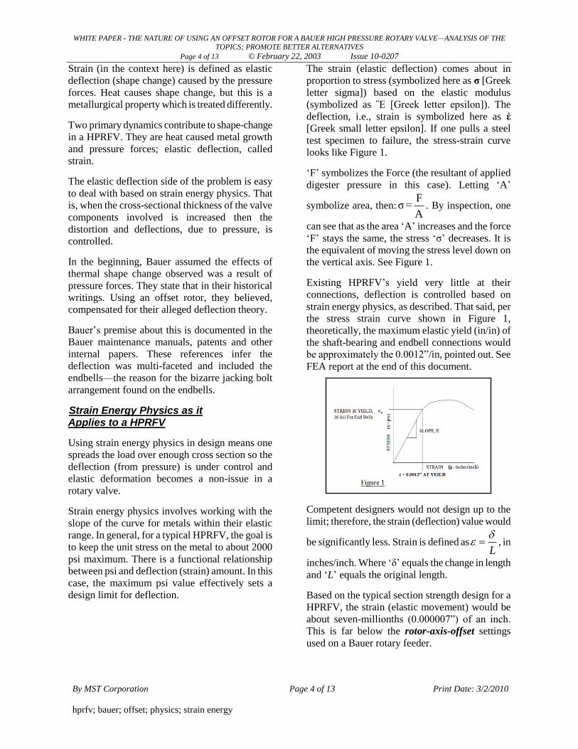
The strain (elastic deflection) comes about in
proportion to stress (symbolized here as σ [Greek
letter sigma]) based on the elastic modulus
(symbolized as Ἓ [Greek letter epsilon]). The
deflection, i.e., strain is symbolized here as ἐ
[Greek small letter epsilon]. If one pulls a steel
test specimen to failure, the stress-strain curve
looks like Figure 1.
„F‟ symbolizes the Force (the resultant of applied
digester pressure in this case). Letting „A‟
symbolize area, then:F
σ=A
. By inspection, one
can see that as the area „A‟ increases and the force
„F‟ stays the same, the stress „σ‟ decreases. It is
the equivalent of moving the stress level down on
the vertical axis. See Figure 1.
Existing HPRFV‟s yield very little at their
connections, deflection is controlled based on
strain energy physics, as described. That said, per
the stress strain curve shown in Figure 1,
theoretically, the maximum elastic yield (in/in) of
the shaft-bearing and endbell connections would
be approximately the 0.0012”/in, pointed out. See
FEA report at the end of this document.
Competent designers would not design up to the
limit; therefore, the strain (deflection) value would
be significantly less. Strain is defined asL
, in
inches/inch. Where „δ‟ equals the change in length
and „L‟ equals the original length.
Based on the typical section strength design for a
HPRFV, the strain (elastic movement) would be
about seven-millionths (0.000007”) of an inch.
This is far below the rotor-axis-offset settings
used on a Bauer rotary feeder.
WHITE PAPER - THE NATURE OF USING AN OFFSET ROTOR FOR A BAUER HIGH PRESSURE ROTARY VALVE—ANALYSIS OF THE
TOPICS; PROMOTE BETTER ALTERNATIVES
Page 5 of 13 © February 22, 2003 Issue 10-0207
By MST Corporation Page 5 of 13 Print Date: 3/2/2010
hprfv; bauer; offset; physics; strain energy
Most of the claims for deflection center on
bending of the shaft. Bending deflection is the
strain (deflection) affects of a moment due to an
applied load—pressure in this case.
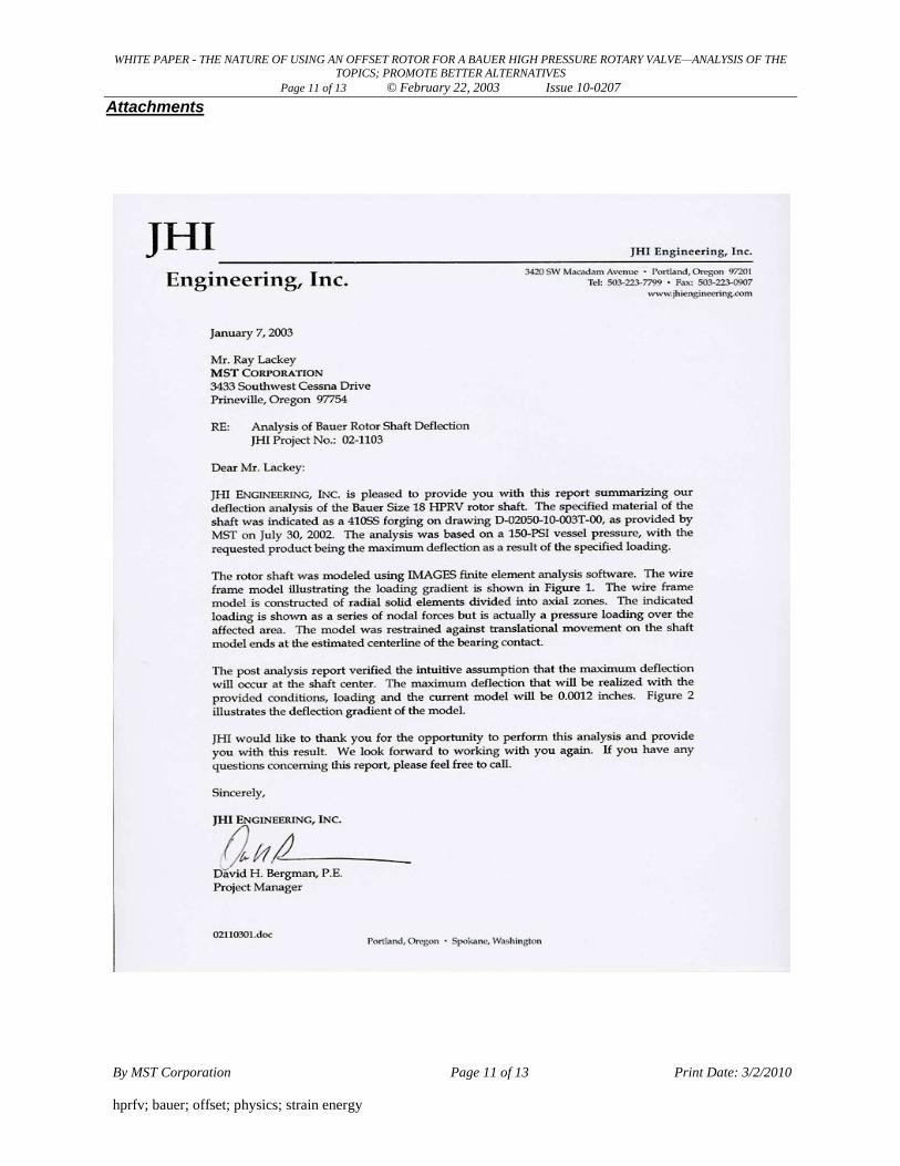
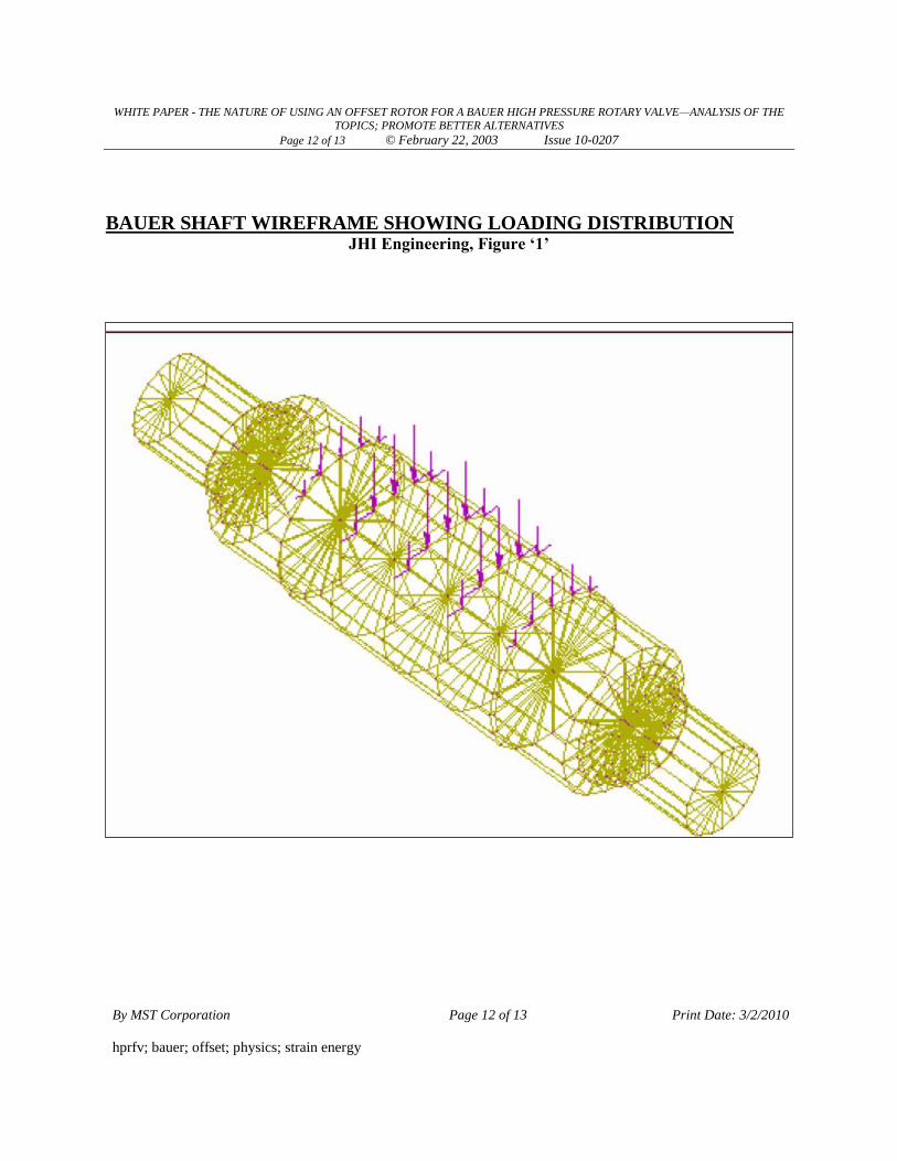
To factor that variable in we contracted with JHI
Engineering to perform a finite elemental analysis
(FEA) to find out the maximum deflection under
the condition of 150-psi digester pressure. Near
the maximum digester pressure one would
normally encounter.
The maximum deflection—in bending—came in
at about 0.0012”. See the JHI report below. This
figure is a maximum because we negated the
resistance effect of the rotor-shaft combination;
the resistance effect of the rotor touching the body
bore and the resistance effect of the packing,
etcetera.
Let us round the 0.028” number to 0.030”for
simplicity. Per the FEA work, the pressure-
induced strain (deflection) affect, combined,
would be less than two-thousands (0.002”) of an
inch. This begs the question, how did they (Bauer)
come up with the roughly thirty-thousand inch that
is common, and why?
The people that do the FEA work agree the basic
thesis in this document is valid and the reason for
the much larger offset Bauer promoted all these
years is not related to deflection as Bauer claimed.
The information here points to several
considerations Bauer overlooked or analyzed
incorrectly, as follows:
1. The original idea (Bauer‟s justification for the
offset) was based on flawed assumptions.
2. Bauer failed to take into account the profile of
the valve based on heat distribution (profile)
at hot thermal equilibrium—hot versus cold—
after a prolonged stable runtime.
3. Non-equilibrium thermal conditions, in terms
of time (transients), are not accounted for in
their theory.
4. HP coupled with torsional friction, resisting
rotation, is a (key) factor that should have
been considered, but was not.
5. Improper startup procedures, and their affects,
are not accounted for using their stated
conclusions.
Is The Premise For The Offset Bauer
(Institutionalized all These Years) Correct?
Elastic deflection does not explain the use of an
axis-offset-down rotor. Only thermal affects on
metals; startup and torsional friction issues, can
explain the run problems that caused them (Bauer)
to construe the need for their offset theory.
One can calculate the strain-equivalent „ε‟ for a
section of each metal type based on the
temperature profile. That value can be introduced
into the stress-strain curve to find its force
equivalent on the curve.
Comparison and analysis about true deflection
from a force versus shape change, due to heat,
helps in understanding the ideas presented here.
For example, it only takes a temperature
differential of about 185 °F to change 1-inch of
the body material an amount equal to the 0.0012”
mark on the curve in Figure 1.
A typical size 18 valve body-bore can vary about
10 times that amount based on a normal stable
thermal profile. It may vary far more when
startups are rushed, like operational upsets and
transient events that imitate conditions as on a
startup.
Another variable: the stainless steel rotor has a
higher coefficient of expansion rate and a higher
equilibrium temperature by comparison. The
stainless steel can vary radially about 54 times the
amount above.
The point is: the different metal properties are
reacting simultaneously to the heat variations. The
combinations are complex, however, the forces
producing deflection due to steam pressure, on the
metal cross sections involved, cannot account for
the offset figures.
WHITE PAPER - THE NATURE OF USING AN OFFSET ROTOR FOR A BAUER HIGH PRESSURE ROTARY VALVE—ANALYSIS OF THE
TOPICS; PROMOTE BETTER ALTERNATIVES
Page 6 of 13 © February 22, 2003 Issue 10-0207
By MST Corporation Page 6 of 13 Print Date: 3/2/2010
hprfv; bauer; offset; physics; strain energy
The original beliefs by the pioneers in this
technology lead to wrong thinking. Likely, they
based their theories on damage assessments and
sketchy field experiences that were not accurate.
Bauer references damage assessment factors in
their patent documents as grounds for “improving
[their] prior art.”
The offset engineering was reactionary
engineering based on operational problems in the
field. The real issue was—and is—how the
thermal profile versus dimensional relationship
variables (metallurgically speaking) affect how the
torsional friction and HP requirements factor into
the mix.
In real life, uniform heating of the rotor takes
place because it (the rotor) rotates over the heat
source. This is not the case for the housing.
The housing bolts to the heat source and therefore
is subject to a thermal profile (gradient) disparity,
bottom to top. During start-up and/or transient
conditions the thermal profile variations are
dynamic.
The housing bore will change from its (round)
close tolerance cold setting to a slight, complex,
egg-shape like form when heated. The rotor,
because of even rotational heating, will stay
round.
The included angle-rotor-to-housing relation will
change because the large end of the rotor grows
(from heat) a greater amount compared to the
small end.
The rotor carves out (wears-in) the bore to remove
the egg-shape and also wears-in to compensate for
the thermally induced different included angles;
rotor versus body-bore.
The included angle of the rotor taper versus body-
bore taper changes from heat and each change
differently with respect to each other because of
the metallurgy involved.
The body bore starts out life round at room
temperature; in the shop. The heat difference at
startup causes the body bore to take on an egg-
shape. As noted, the rotor stays round because it is
rotating over the heat source. Imagine what we
have just described:
We have described a condition whereby a new or
cold valve is trying to fit a round rotor into an egg-
shaped body bore; both conditions due to the
nature of the thermal effects on startup. It is the
round peg into a square hole allegory. In this case,
a round peg into an egg-shaped hole.
The offset was a tool (if you will) used to
compensate for that round peg into the egg-shaped
hole dilemma. In addition, this dilemma
effectively increased the power requirement as a
direct result of the high torsional friction load it
caused.
In sum, the offset was not needed because of
deflection, it was needed because the valves did
not have enough power to drive through the break-
in period. After about 8-hours of uninterrupted
operation the rotor and body become thermally
stabilized.2 Bauer does not deny the fact it takes
about 8-hours; they refer to it in their manuals, etc.
After stabilization has occurred, the body bore is
still egg-shaped because the body is static; not
rotating like the rotor; different temperature
bottom-to-top.
The offset rotor did not seal as well as one fully
worn to fit, but it got them by the fitful stalls
etcetera related to the torsional friction problem
for the duration of the time needed to wear into the
bore until it fit, creating an optimal seal, rotor to
body.
The full offset amount (nominally about 0.028” on
high pressure applications) requires the body-bore
to wear-in (become round at hot equilibrium
status) until the offset, in effect, disappears, or,
more correctly stated; until the egg shape
disappears at hot equilibrium operation.
Moving the rotor down 0.028” toward the bottom
doubles the clearance at the top,
2 0.028" 0.056"x , the true offset relative to the
body bore surface.
2 Thermally stabilized defines the status whereby the valve parts stay
at their normal temperature, and start-out shape (known as a hot
equilibrium state), for a prolonged period of time. Long enough to
reshape the body bore back to a round condition based on the rotor wearing to fit.
WHITE PAPER - THE NATURE OF USING AN OFFSET ROTOR FOR A BAUER HIGH PRESSURE ROTARY VALVE—ANALYSIS OF THE
TOPICS; PROMOTE BETTER ALTERNATIVES
Page 7 of 13 © February 22, 2003 Issue 10-0207
By MST Corporation Page 7 of 13 Print Date: 3/2/2010
hprfv; bauer; offset; physics; strain energy
The taper ratio is 6 to 1 per side. The design for
the valve calls for the ability of the rotor to move
toward the small end 1-inch during a valve
lifecycle.
By design, the Bauer valve unit has a theoretical
lifecycle equal to the 1-inch of axial travel. The
rotor will fit the body bore all around (at hot
equilibrium) when the axial travel reaches about 3/8”, i.e.,6 0.056" 0.360"x .
The effect is the bore—in operation—moves
(because of wear) to the same axis of the rotor.
This occurs over time, as the rotor is moved
(wears-in) axially toward the small end; known as
the break-in period.
The break-in period varies depending on the skill
of operators in combination with the usable
horsepower at the drive shaft. Overcoming
torsional friction variables during the shaping
(rounding) time period is functionally realted to
these two chief variables.
The valve is designed for a lifecycle defined as 1-
inch total axial travel, then by definition, after the
0.056” top gap disapears; because the rotor
effectively laps itself into the body bore until it fits
all around.
At the point the 0.056” top gap is gone; and
because the rotor is fixed in the bearing centers,
the rotor and its shaft centerline become the same
as the lapped in bore. This leaves about ¾” of
axial lifecycle left.
One could ask: if the rotor being offset is a
requirement why the discrepancy; most of the
designed lifecycle of the valve takes place after the
offset is gone?
Assuming one has enough HP to overcome the
torsional friction, then that last approximately ¾”
of movement takes place without the existence of
any offset (radial difference), top, sides, or
bottom.
It is very important to recognize the part HP plays
in the successful (trouble free) operation of a
Bauer valve.
Horsepower is what determines if the users can
maintain a close (minimal radial clearance) rotor
to body seal fit. One can see there is a functional
relationship between; (1) radial clearance, (2) HP
and (3) amperage. These three factors can be
varied to improve opetations.
The power available at the drive is a controlling
factor as to how friendly the valve will seem to the
operators throughout the valve lifecycle. Higher
HP always will help make operations seem
friendlier during startups and/or transients.
In a metallurgical sense, it takes about eight hours
for a HPRFV to reach true thermal equilibrium.
When the startup is pushed too quickly or there is
operational thermal upsets. The bottom to top
thermal gradient causes shape change.
The thermal bore distortion increases and there is
a greater torsional frictional resistance. That is, a
greater demand for power to compensate for the
increased frictional resistance. The valve tends to
stall or act erratically.
Operationally, a taper plug rotary valve is all
about power (usable HP) because the rotor-to-
body clearance control is functionally regulated by
monitoring—and maintaining—the amperage
(friction) range for the drive.
The amperage range (by Bauer‟s definition of how
to operate) tells the operators when the taper rotor
is seated, based on amperage, functionally related
to an acceptable level of friction versus the
functional relation to motor size
There has been a tendency—over the years—to
increase horsepower to compensate for amperage
kick-outs compared with the original lower
horsepower units. Nothing is more frustrating to
an operator than to be saddled with an
underpowered valve or a valve that looses too
much power through the drive train, etcetera.
The higher HP helps, as the rotor-to-body seat
tightens up over time. However, reserve power is
what eases the burden on the operators and
operations.
WHITE PAPER - THE NATURE OF USING AN OFFSET ROTOR FOR A BAUER HIGH PRESSURE ROTARY VALVE—ANALYSIS OF THE
TOPICS; PROMOTE BETTER ALTERNATIVES
Page 8 of 13 © February 22, 2003 Issue 10-0207
By MST Corporation Page 8 of 13 Print Date: 3/2/2010
hprfv; bauer; offset; physics; strain energy
The worn-in fit makes the better seal, but is more
sensitive to the increased friction loads related to
the thermal transients described. The transient
friction factors, in general, increases the HP
demand based on higher torsional friction.
The thermal issues outlined above (in combination
or individually) give rise (no pun intended) to
false speculations and analyses. The original
theory for the offset persists based on perpetuated
and mistaken conclusions first promulgated in the
1950‟s.
Using the knowledge condensed here, it is
possible to pre-shape the body bore to provide all
the benefits an offset may provide with the added
improvements available when all axial
relationships are coincident—the same.
Benefits like improved sealing and sealing
options. Longer life in the packing system; the
bearing seals and packing are truly on center;
simpler maintenance (no offset bearing sleeve
required) and etcetera.
So Why Does a Rotor &Shaft-Axis (Original Bauer)-Offset Seem to Work?
The exact events leading to the false conclusion
for the offset value are lost in the past. However,
based on forensic analysis and reverse engineering
work the following conclusions can be inferred:
The rotor is stainless steel and the body is
mild steel.
Originally they manufactured the rotor and the
body without an offset.
The coefficient of thermal expansion
between these two metals is a net difference
of:
63.5
[( )/ /deg
( )]
x Operating temp Roomtempin in F
x total inches
The greatest growth takes place with the
stainless steel.
The top side of the bore is less temperature
than the bottom side. Hence an inherent egg
shaped bore surface on a new or cold valve.
The real time reaction to too much friction
(high amp loads) is not quick enough because
it is fundamentally manually controlled and
the information feedback for the operators‟
places the operator at a disadvantage.
The rotor back-off (after touching) specification
for startup (see Bauer startup procedure) of the
valve is 3 to 4 seconds on the limit torque based
on amperage feedback (the touchdown indication).
This translates to about 0.003” axial movement;
about 5-ten thousands (0.0005”) increased radial
clearance. Note: based on the limits of amperage
(HP) the correct running clearance, by definition,
becomes the ongoing seated rotor control
reference.
Based on the differential growth of the body
versus the rotor and the uneven profile, bottom to
top of the body, these factors can lead to rubbing
contact severe enough to cause stalling problems.
Depending on the rate of heat-up (thermal shape
change) the interference at the top (rotor versus
body-bore) may range from a theoretical minimum
of 0.012” to a maximum of about 0.060” for the
high pressure units on new valve startups.
The actual values depend on warm-up rates and/or
rates of change initiated by transient events.
Originally, they (Bauer) misinterpreted the
difference as “deflection” of the rotor due to
pressure. In the case of steam there is a functional
relation between pressure and temperature. As
such, there is a quasi metallurgical relationship;
temperature versus pressure.
Different temperatures at different pressures (the
functional relationship) better explains the
historical offset range of 0.012” to 0.040” (0.024”
to 0.080” at the top) based on pressure and valve
size for all sizes of valves, as noted in the Bauer
documentation—tables.
The rotor stays round because it rotates over the
heat source (like a Bar-B-Q spit); heats uniformly
and is equal to the vessel temperature.
WHITE PAPER - THE NATURE OF USING AN OFFSET ROTOR FOR A BAUER HIGH PRESSURE ROTARY VALVE—ANALYSIS OF THE
TOPICS; PROMOTE BETTER ALTERNATIVES
Page 9 of 13 © February 22, 2003 Issue 10-0207
By MST Corporation Page 9 of 13 Print Date: 3/2/2010
hprfv; bauer; offset; physics; strain energy
For the tapered rotor to seat, it is necessary to
wear-in the egg-shape body bore to fit the round
rotor and to rematch (wear-to-fit) the included
angle of both rotor and body-bore, over a steady
hot-equilibrium run-time period; the time is
functionally related to available power.
The perceived contact at the top of the bore—
because of thermal shape change—lead to the
view they (Bauer) needed to back off the rotor
axially. That is, move the rotor back, then down,3
which lead to the general rotor setting on a cold
valve assembly.
In the one sense they overlooked the thermal
dimensional changes described. However, in
another sense, by shifting the rotor to a rotor-axis-
offset-down—in a crude way—it dealt with the
thermal distortion problem—albeit a quasi do-it-
yourself (partial) solution.
At the same time they were closing the rotor to
body clearance on the pressure side of the rotor;
essentially, providing a quasi seal on the pressure
side long enough for the rotor to wear (round up)
the egg-shape bore profile.
Creating an axis-offset-down-rotor was an
indirect way to make operation friendlier,
specifically when the HP was inadequate for the
operational conditions. That is, when the valve
assembly distorts from uneven heating.
Some wear-in is always required, especially on
start-up and during the break-in period because of
heat distortions; noted. The Bauer offset is
effectively a crude built-in HP (amperage) control
mechanism when the body is moving around due
to uneven heating and initial wear-in is taking
place.
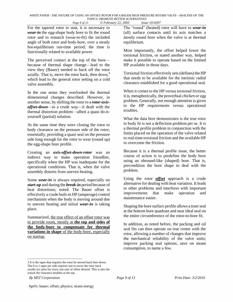
Summarized, the true effect of an offset rotor was
to provide room, mostly at the top and sides of
the body-bore to compensate for thermal
variations in shape of the body-bore, especially
on startup.
3 It is the taper that requires the rotor be moved back then down.
The 6 to 1 taper per side requires one to move the rotor back
axially six units for every one unit of offset desired. This is also the reason the clearance doubles at the top.
The “round” (heated) rotor will have to wear-in
(all) surface contacts until its axis matches a
mostly round bore when the valve is at thermal
equilibrium.
Most importantly, the offset helped lower the
torsional friction, or stated another way, helped
make it possible to operate based on the limited
HP available in those days.
Torsional friction effectively sets (defines) the HP
that needs to be available for the intrinsic radial
clearance established for a good operational seal.
When it comes to the HP versus torsional friction,
it is, metaphorically, the proverbial chicken or egg
problem. Generally, not enough attention is given
to the HP requirements versus operational
troubles.
What the data here demonstrates is the true rotor
to body fit is not a deflection problem per se. It is
a thermal profile problem in conjunction with the
limits placed on the operation of the valve related
to real-time torsional friction and the available HP
to overcome the friction.
Because it is a thermal profile issue, the better
course of action is to predefine the body bore
using an obround-like (shaped) bore. That is,
precondition the bore shape to deal with the
problem.
Using the rotor offset approach is a crude
alternative for dealing with heat variation. It leads
to other problems and interferes with important
improvements that make operation and
maintenance easier.
Shaping the bore surface profile allows a truer seal
at the bottom bore quadrant and near ideal seal on
the entire circumference of the rotor-to-bore fit.
In addition, as noted before, the packing and oil
seal fits can then operate on true center with the
rotor, allowing a number of changes that improve
the mechanical reliability of the valve units;
improve packing seal options; save on steam
consumption, to name a few.
WHITE PAPER - THE NATURE OF USING AN OFFSET ROTOR FOR A BAUER HIGH PRESSURE ROTARY VALVE—ANALYSIS OF THE
TOPICS; PROMOTE BETTER ALTERNATIVES
Page 10 of 13 © February 22, 2003 Issue 10-0207
By MST Corporation Page 10 of 13 Print Date: 3/2/2010
hprfv; bauer; offset; physics; strain energy
The goal here is to make known information that
will help Bauer valve users see ways for Bauer
valve improvements that will advance technology
in this field and promote the advantages of having
the seal area, packing area and rotor to body
coaxial relationship.
The Better Method(s)- Reassessment-Time Tested MST-Bauer CenterSeal™ Design & Related Improvements:
Summing up, a controlled bore surface profile
method, i.e., CenterSeal™ design—coupled
with reassessment of one‟s HP and drive
limitations, etcetera—directly deals with the true
issue outlined here.
That is, the historical offset rotor method was
based on a flawed theory and is cause for
numerous operational problems to this day.
Ray Lackey
Go to attachments:
WHITE PAPER - THE NATURE OF USING AN OFFSET ROTOR FOR A BAUER HIGH PRESSURE ROTARY VALVE—ANALYSIS OF THE
TOPICS; PROMOTE BETTER ALTERNATIVES
Page 11 of 13 © February 22, 2003 Issue 10-0207
By MST Corporation Page 11 of 13 Print Date: 3/2/2010
hprfv; bauer; offset; physics; strain energy
Attachments
WHITE PAPER - THE NATURE OF USING AN OFFSET ROTOR FOR A BAUER HIGH PRESSURE ROTARY VALVE—ANALYSIS OF THE
TOPICS; PROMOTE BETTER ALTERNATIVES
Page 12 of 13 © February 22, 2003 Issue 10-0207
By MST Corporation Page 12 of 13 Print Date: 3/2/2010
hprfv; bauer; offset; physics; strain energy
BAUER SHAFT WIREFRAME SHOWING LOADING DISTRIBUTION JHI Engineering, Figure ‘1’
WHITE PAPER - THE NATURE OF USING AN OFFSET ROTOR FOR A BAUER HIGH PRESSURE ROTARY VALVE—ANALYSIS OF THE
TOPICS; PROMOTE BETTER ALTERNATIVES
Page 13 of 13 © February 22, 2003 Issue 10-0207
By MST Corporation Page 13 of 13 Print Date: 3/2/2010
hprfv; bauer; offset; physics; strain energy
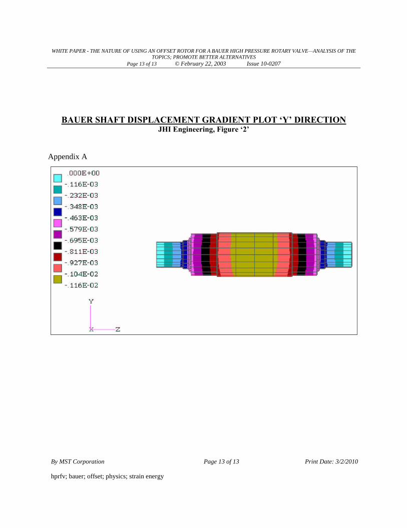
BAUER SHAFT DISPLACEMENT GRADIENT PLOT ‘Y’ DIRECTION JHI Engineering, Figure ‘2’
Appendix A
Recommended