Multi-blademonolithicEulerspringswithoptimisedstressdistribution
J.V.vanHeijningen1,†,J.Winterflood1andL.Ju11OzGrav-UWAnode,UniversityofWesternAustralia,35StirlingHwy,CrawleyWA6009,AustraliaE-mail:†[email protected]
Abstract.Eulerspringsareusedforverticalsuspensionandvibrationisolationastheyprovidealargestaticsupportingforcewithlowspring-rateanduseminimalspringmaterial.Todatemultiplesingle-width,vertically-stacked,rectangularbladesofuniformthicknesshavebeenusedinthepostbuckledstate,withhalfofthenumberbucklingineachofopposingdirections.Thisstructurerequiresclampingtheendsofthebladesgivingstick-slipproblems.Inthisstudyweinvestigatethebenefitsofformingmultiple,oppositelybucklingblades,side-by-sidefromasinglemonolithicsheetofspringmaterial.Weinvestigatehowtodistributethestressevenlyalongthelengthofthebladebycontouringitswidth,aswellasfindingtheoptimaljoiningcontourtodistributethestressevenlyaroundthetearingjointsbetweenoppositelybendingblades.
Keywords:Gravitationalwaves,Vibrationisolation,Eulersprings,Seismicnoise
Introduction Withthefirstdetectionofgravitationalwaves(GWs)[1],weasmankindhavemadeourmostprecisedistancemeasurementtodate.ThefirstcoincidencemeasurementofGWswithelectromagneticcounterparts,GW170817,fromabinaryneutronstarmerger[2,3]hasprovidedafirmbasisforthenewlyfoundedfieldofmulti-messengergravitationalwaveastronomy.
AllthesemonumentalmeasurementswouldnothavebeenpossiblewithoutdecouplingthetestmassesofthedetectorsfromtheEarth’sever-presentseismicmotion.VibrationisolationsystemsareusedinallGWdetectors.Isolatedobjectsapproximatethenotionofafreelyfalling(test)massintheaxisofinterestforGWdetection,i.e.thedirectioninlinewithmainlaserbeam.Howeverthemulti-kilometreextentofthelasercavitiesandfiniteradiusoftheearthmeansthatthegravitationalpullonthetestmassesateachendisnotperpendiculartothecavity,butactsonaslightangle(afractionofamrad)tothesensingaxis.Thisangle, together with construction tolerances (which couple vertical-to-horizontal motion) mean thatverticalvibrationisolationhasbeenalmostascriticalashorizontalisolationinallGWdetectionefforts.
Themeasurementsensitivityat thetestmassexceedsthatofanyavailablesensor,sothe laststagesofvibrationisolationnecessarilyconsistofpassivemechanicalspring-massstagescascadedoneaftertheothertoachievetherequiredisolation.Variousstylesofspring-massstructureshavebeendevelopedfortheGinginHighPowerOpticalTestFacility[4,5],operatedbytheUniversityofWesternAustralia(UWA),Advanced Virgo [6] and KAGRA [7]. Vertical vibration isolation is achieved in Advanced Virgo withhorizontal cantilever springswith somemagnetic non-linearity added to provide some anti-spring [8]aroundtheoperatingregiontolowertheresonancefrequency.InKAGRA,buildingontheexperienceofTAMA300[10],GeometricAnti-Spring(GAS)[9]structuresareused.Thesealsousecantileversprings,butsetatanangleupfromhorizontal,witheachcantilevercompressedlongitudinallyagainstapartnerwithmirrororradialsymmetry,toachievesomenon-linearsnap-througheffectwhichlowerstheresonancefrequencyaroundtheoperatingregion.
Bothoftheseapproacheshavealargeamountofverticalsuspensionenergy(mgdhofinitialdeflectionh)storedinthespringmaterialwhichnecessitatesalargespringmasscommensuratewiththeenergystored.The GAS structure even has a significant fraction of additional stored energy in the longitudinalcompressionwhichactsasananti-springtocancelmostofthenormalspringcoefficient.BycontrasttheUWAisolatorsemployEulersprings[11]whichstorenoenergyuntilloadedwithsufficientweighttocausethemtobuckle,afterwhichtheyfeaturelowstiffnessandrelativelyhighfrequencyinternalmodes(duetominimalmass)whenoperatinginthepostbuckledstate.Lowstiffnessisdesirableasitdeterminesthespring-massresonanceandthustheseismicfiltercut-offfrequency,whilehighfrequencyinternalmodesaredesirableasthesemodessetthefrequencyabovewhichtheseismicfilteringbecomesineffective.
Herewedescribeanoveldesignofthebuckledcolumn.Earlierwehaveshown[17]thatthesquarenessofthe knee in the force-displacement characteristic at the onset of buckling is extremely sensitive to thelaunchingangle.Theslightesttendencyforthecolumntobuckleoutononesideinpreferencetotheotherproducingaveryroundedkneewithconsequentdetrimentalhighresonance frequencywhenoperatednearthebucklingpoint.Wehavealsoshown[17]thatwhenthelaunchingangleateachendofthecolumnareequallybutoppositelyoffset—sothattheunbuckledbladestartsasagentle”S”shape,andthecolumn

hasnopreferreddirectioninwhichtobuckle—thenagainthekneebecomessquareandtheresonancefrequencylow.
This sensitivity to launching angle becomesparticularly problematicwhen the ends of the columnsorbladesareclamped.Thereasonbeing thatwithuniformthicknessblades, theregionsofhighest stress(necessarilyalargefractionofyield)occurrightwherethebladeslaunchfromtheclamps.Theslighteststick-slipmotionbetweenthehighlystressedbladesurfaceandtherelativelyunstressededgeoftheclampproducesanon-zero launchinganglewhichspoils thesquarenessof thebucklingknee.Manytimeswewouldfindthatthefirstbucklingcyclehadasquareforce-displacementcharacteristic,whilesubsequentcycleswerebadlyrounded.Sincethebladematerialwaswellbelowyield,weputthisdowntostick-slipmotionbetweenbladeandclampingjawsatthelaunchingpoint.
Theobvioussolutiontothisproblemistousemonolithicratherthanclampedboundariesattheendsoftheblades.Thebestdesignwouldseemtobeastepchangeinbladethicknessatthelaunchingpointsothatclampingwouldbedoneonathickpartwithlowlevelsofstressandnotendencytostick-slip.Producingastepchangeinthickness,whilepossible,presentsdifficultieswhenthebestspringmaterialcomesreadyinthinsheets,andthetolerancesrequiredformachiningthethicknessareverysmall.Forthisreasonwedecidedtotryslottingthefaceofauniformthicknessspringbladelengthwise—sothathalfofthebladematerialbowsoutinonedirectionwhiletheotherhalfbowsintheoppositedirection.Thehighstressesthenoccuratthe”tearing”jointswheresectionsofthebladearebendinginoppositedirections,andthebladecanbeclampedsomedistanceawayfromthesejoints,inanareawherethestressismuchreduced.
InadditiontomakingtheendboundariesoftheEulerspringsmonolithicbyslottingasinglespringsheettoallowparallelside-by-sidestripswithopposingbends,wealsodecidedtoevenoutthestressdistributionalongeachstripbycontouringthewidth(notthickness)ofeachstripalongitslengthandvaryingtheshapeofthetearingjointtoevenoutthestressdistributioninthatregion.
In section 1we present ourmethod to determine the optimal blade shape forwhichwe calculate thetheoreticalstiffness insection2.Subsequentfiniteelementanalysisonthe impactofcontouringonthenominalloadandbladestressisdescribedinsection3.Resultsofperformancemeasurementsofthedesignappliedtoaglassymetalsampleareshowninsection4.Weendwithconclusionsandfutureprospects.
1.DeterminingtheoptimalcontouredEulerspringblade WhenaconstantwidthEulerspring,clampedatbothends,islongitudinallycompresseduntilitbuckles,itwilltakeontheshapeofanelastica.Thisshape,however,hasanunevenstressdistributionwithmaximumstressattheendsandmidpoint[12].Inordertominimisethespringmassforagivenload,thethincolumnorbladeundergoingEulerbucklingshouldhaveuniformstressdistribution.Ifthethicknessofthebladematerialisconstant,thenthematerialwillbeevenlystressedwhenitisbenttoaconstantradius—formingsegmentsofcirculararcsasshownintheedgeviewofFig.1.
Inordertoobtainconstantradiusofbend,theareamomentofinertiashouldvaryindirectproportiontotheappliedmoment.Sincepointsofinflectionalongtheblademarkspotswithzeromoment,theline-of-actionoftheappliedforcemustbeastraightlinethroughthesepointsofinflectionandtheappliedmomentmustbeproportionaltothedistanceofthebladefromthisline.Sincethebladethicknessistobeconstant,themomentofinertiaisproportionaltothewidth,andsothewidthofthebladeshouldbemadedirectlyproportional to itsdisplacementwhenmaximallybuckled, from the line-of-action.Thisproportionalityappearsasthestraightlinesofabow-tieshapeintheendviewofFig.1wherethewidthofthematerialiszeroatthepointsofinflectionandmaximumatthepointsofmaximummoment.
Since the constant radius curvature of the thin springmakes it part of a cylinder, and the profile cutsrequiredareplaneswhichcutthiscylinder,itfollowsthattheresultingshapeswhichappearprojectedintheprofileviewmustbearcsofellipsesasshownintheprofileviewofFig.1.Whileanellipseistheshapeinprojection, thecurvedoesnotremainanellipseshapeonce thematerialhasbeen flattenedout. Ifacylinderiscutatsomeanglewithaplaneandthenunrolled,theshapeofthecutedgeisinsteadasinusoid.Inotherwords,theshapetobecutoutoftheflatmaterialaresegmentsofasinusoidcurve.
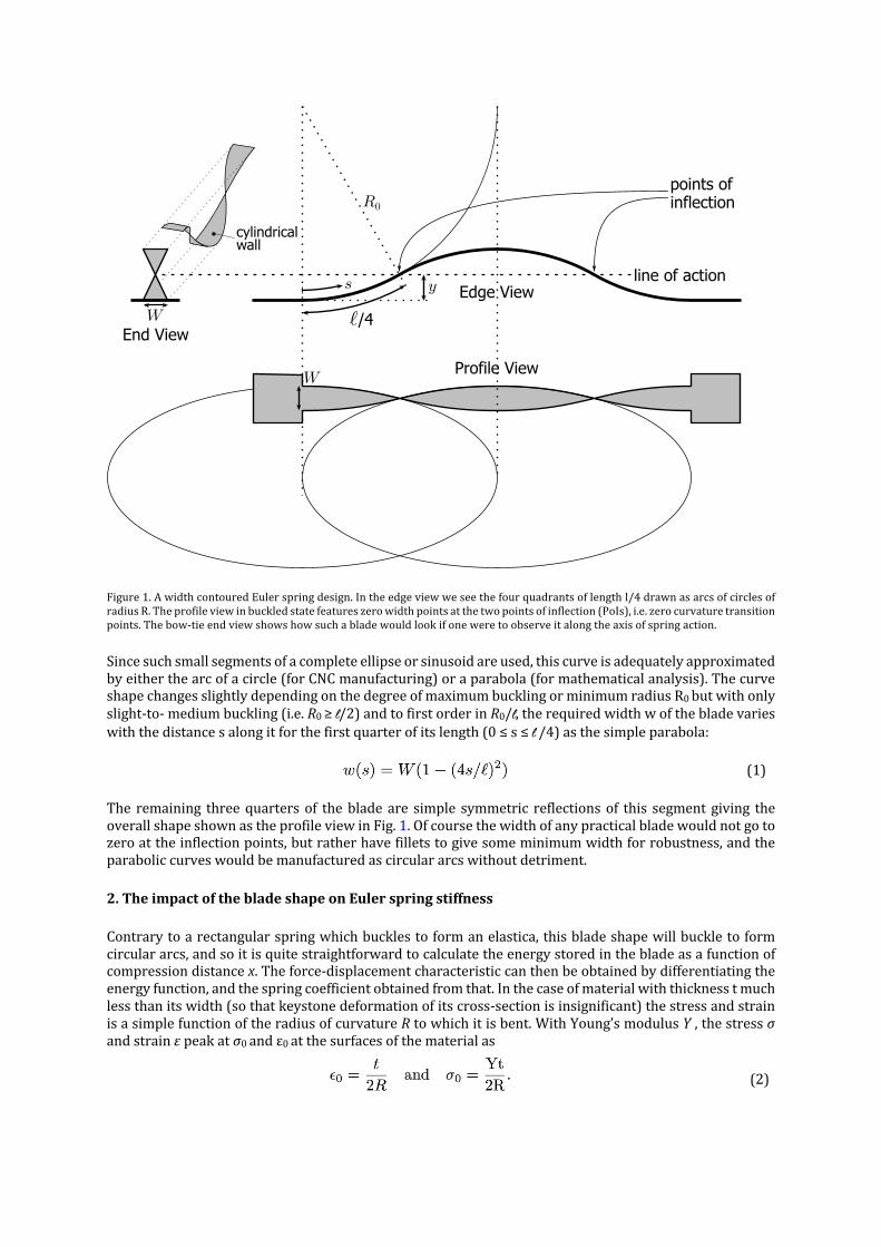
Figure1.AwidthcontouredEulerspringdesign.Intheedgeviewweseethefourquadrantsoflengthl/4drawnasarcsofcirclesofradiusR.Theprofileviewinbuckledstatefeatureszerowidthpointsatthetwopointsofinflection(PoIs),i.e.zerocurvaturetransitionpoints.Thebow-tieendviewshowshowsuchabladewouldlookifoneweretoobserveitalongtheaxisofspringaction.
Sincesuchsmallsegmentsofacompleteellipseorsinusoidareused,thiscurveisadequatelyapproximatedbyeitherthearcofacircle(forCNCmanufacturing)oraparabola(formathematicalanalysis).ThecurveshapechangesslightlydependingonthedegreeofmaximumbucklingorminimumradiusR0butwithonlyslight-to-mediumbuckling(i.e.R0≥l/2)andtofirstorderinR0/l,therequiredwidthwofthebladevarieswiththedistancesalongitforthefirstquarterofitslength(0≤s≤l/4)asthesimpleparabola:
(1)
The remaining threequartersof thebladeare simple symmetric reflectionsof this segment giving theoverallshapeshownastheprofileviewinFig.1.Ofcoursethewidthofanypracticalbladewouldnotgotozeroattheinflectionpoints,butratherhavefilletstogivesomeminimumwidthforrobustness,andtheparaboliccurveswouldbemanufacturedascirculararcswithoutdetriment.
2.TheimpactofthebladeshapeonEulerspringstiffness
Contrarytoarectangularspringwhichbucklestoformanelastica,thisbladeshapewillbuckletoformcirculararcs,andsoitisquitestraightforwardtocalculatetheenergystoredinthebladeasafunctionofcompressiondistancex.Theforce-displacementcharacteristiccanthenbeobtainedbydifferentiatingtheenergyfunction,andthespringcoefficientobtainedfromthat.Inthecaseofmaterialwiththicknesstmuchlessthanitswidth(sothatkeystonedeformationofitscross-sectionisinsignificant)thestressandstrainisasimplefunctionoftheradiusofcurvatureRtowhichitisbent.WithYoung’smodulusY,thestressσandstrainεpeakatσ0andε0atthesurfacesofthematerialas
(2)
Edge View
End View
Profile View
line of action
cylindricalwall
points ofinflection
/4
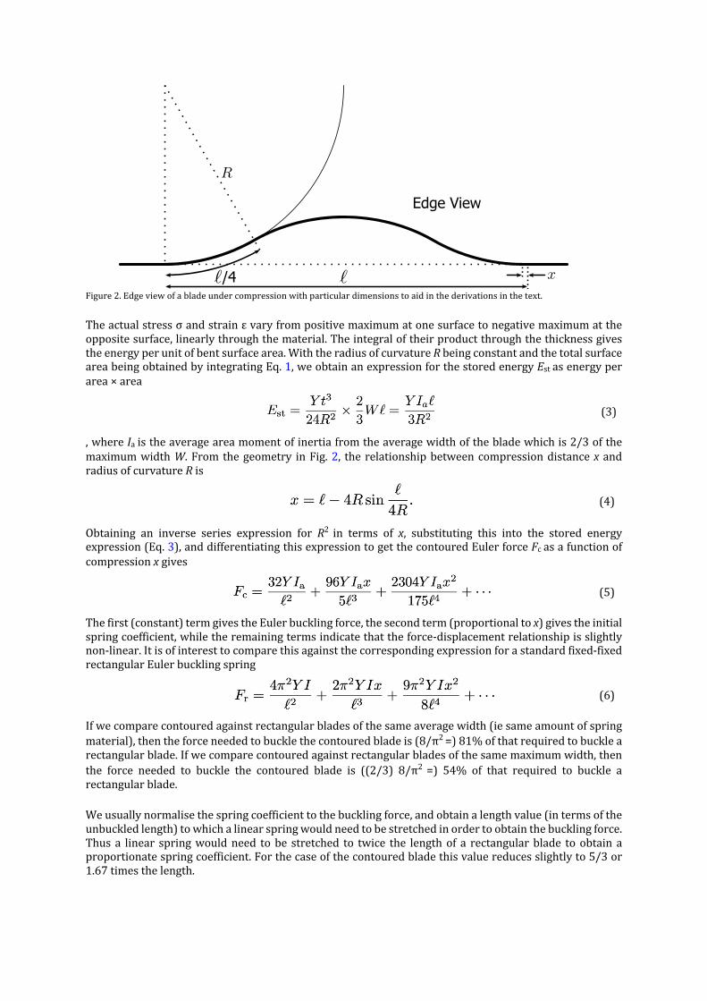
Figure2.Edgeviewofabladeundercompressionwithparticulardimensionstoaidinthederivationsinthetext.
Theactualstressσandstrainεvaryfrompositivemaximumatonesurfacetonegativemaximumattheoppositesurface,linearlythroughthematerial.Theintegraloftheirproductthroughthethicknessgivestheenergyperunitofbentsurfacearea.WiththeradiusofcurvatureRbeingconstantandthetotalsurfaceareabeingobtainedbyintegratingEq.1,weobtainanexpressionforthestoredenergyEstasenergyperarea×area
(3)
,whereIaistheaverageareamomentofinertiafromtheaveragewidthofthebladewhichis2/3ofthemaximumwidthW.Fromthegeometry inFig.2, therelationshipbetweencompressiondistancex andradiusofcurvatureRis
(4)
Obtaining an inverse series expression for R2 in terms of x, substituting this into the stored energyexpression(Eq.3),anddifferentiatingthisexpressiontogetthecontouredEulerforceFcasafunctionofcompressionxgives
(5)
Thefirst(constant)termgivestheEulerbucklingforce,thesecondterm(proportionaltox)givestheinitialspringcoefficient,whiletheremainingtermsindicatethattheforce-displacementrelationshipisslightlynon-linear.Itisofinteresttocomparethisagainstthecorrespondingexpressionforastandardfixed-fixedrectangularEulerbucklingspring
(6)
Ifwecomparecontouredagainstrectangularbladesofthesameaveragewidth(iesameamountofspringmaterial),thentheforceneededtobucklethecontouredbladeis(8/π2=)81%ofthatrequiredtobucklearectangularblade.Ifwecomparecontouredagainstrectangularbladesofthesamemaximumwidth,thenthe force needed to buckle the contoured blade is ((2/3) 8/π2 =) 54% of that required to buckle arectangularblade.
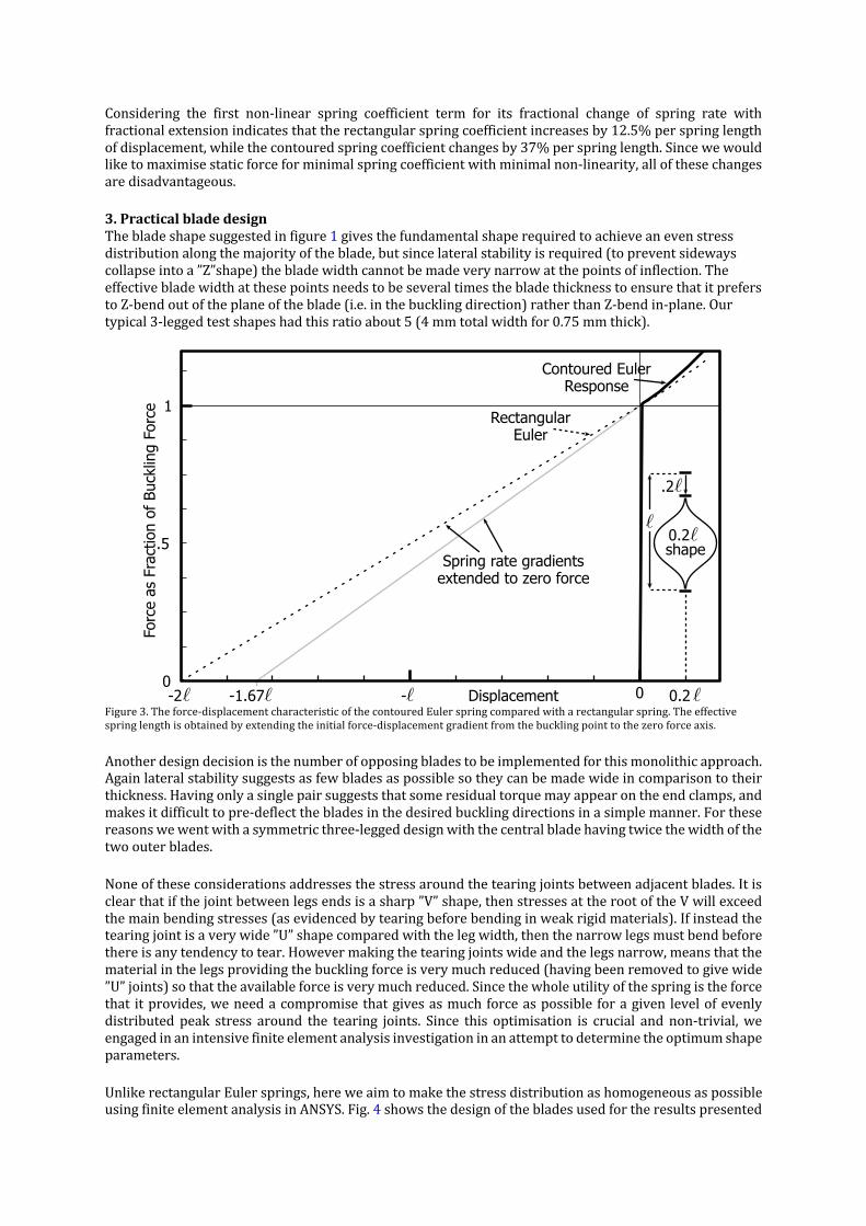
Weusuallynormalisethespringcoefficienttothebucklingforce,andobtainalengthvalue(intermsoftheunbuckledlength)towhichalinearspringwouldneedtobestretchedinordertoobtainthebucklingforce.Thusa linear springwouldneed tobe stretched to twice the lengthof a rectangularblade toobtainaproportionatespringcoefficient.Forthecaseofthecontouredbladethisvaluereducesslightlyto5/3or1.67timesthelength.
Edge View
/4
Considering the first non-linear spring coefficient term for its fractional change of spring rate withfractionalextensionindicatesthattherectangularspringcoefficientincreasesby12.5%perspringlengthofdisplacement,whilethecontouredspringcoefficientchangesby37%perspringlength.Sincewewouldliketomaximisestaticforceforminimalspringcoefficientwithminimalnon-linearity,allofthesechangesaredisadvantageous.
3.Practicalbladedesign Thebladeshapesuggestedinfigure1givesthefundamentalshaperequiredtoachieveanevenstressdistributionalongthemajorityoftheblade,butsincelateralstabilityisrequired(topreventsidewayscollapseintoa”Z”shape)thebladewidthcannotbemadeverynarrowatthepointsofinflection.TheeffectivebladewidthatthesepointsneedstobeseveraltimesthebladethicknesstoensurethatitpreferstoZ-bendoutoftheplaneoftheblade(i.e.inthebucklingdirection)ratherthanZ-bendin-plane.Ourtypical3-leggedtestshapeshadthisratioabout5(4mmtotalwidthfor0.75mmthick).
Figure3.Theforce-displacementcharacteristicofthecontouredEulerspringcomparedwitharectangularspring.Theeffectivespringlengthisobtainedbyextendingtheinitialforce-displacementgradientfromthebucklingpointtothezeroforceaxis.
Anotherdesigndecisionisthenumberofopposingbladestobeimplementedforthismonolithicapproach.Againlateralstabilitysuggestsasfewbladesaspossiblesotheycanbemadewideincomparisontotheirthickness.Havingonlyasinglepairsuggeststhatsomeresidualtorquemayappearontheendclamps,andmakesitdifficulttopre-deflectthebladesinthedesiredbucklingdirectionsinasimplemanner.Forthesereasonswewentwithasymmetricthree-leggeddesignwiththecentralbladehavingtwicethewidthofthetwoouterblades.
Noneoftheseconsiderationsaddressesthestressaroundthetearingjointsbetweenadjacentblades.Itisclearthatifthejointbetweenlegsendsisasharp”V”shape,thenstressesattherootoftheVwillexceedthemainbendingstresses(asevidencedbytearingbeforebendinginweakrigidmaterials).Ifinsteadthetearingjointisaverywide”U”shapecomparedwiththelegwidth,thenthenarrowlegsmustbendbeforethereisanytendencytotear.Howevermakingthetearingjointswideandthelegsnarrow,meansthatthematerialinthelegsprovidingthebucklingforceisverymuchreduced(havingbeenremovedtogivewide”U”joints)sothattheavailableforceisverymuchreduced.Sincethewholeutilityofthespringistheforcethat itprovides,weneedacompromisethatgivesasmuchforceaspossible foragiven levelofevenlydistributed peak stress around the tearing joints. Since this optimisation is crucial and non-trivial,weengagedinanintensivefiniteelementanalysisinvestigationinanattempttodeterminetheoptimumshapeparameters.
UnlikerectangularEulersprings,hereweaimtomakethestressdistributionashomogeneousaspossibleusingfiniteelementanalysisinANSYS.Fig.4showsthedesignofthebladesusedfortheresultspresented
-2 --1.67
Forc
e as
Fra
ctio
n of
Buc
klin
g Fo
rce 1
.5
Displacement 0 0.2
Contoured EulerResponse
RectangularEuler
Spring rate gradientsextended to zero force
.2
shape0.2
0

intherestofthispaper.TheshapeoftheEulerspringasshowninthefigurewereoptimisedforamaximumFload2/σmax.Theaboveexpressionaims tooptimise thedesire for ahighnominal load supportedby thebuckledbladewhilekeepingthemaximumstressaslowaspossible.Alowmaximumstressresultsfromahighlyhomogeneousstressdistribution.Themaximumstress in thesedesignswill alwaysoccurat thesharpbendsbetweentheindividualbladeclosetotheclampingsurfacesofthesprings(seeexamplereddotinFig.4(a)).Inthatoptimisationexpression,wecanchosetogiveweighttoeitherthenominalloadorthehomogeneousstressby,forinstance,raisingFloadtoacertainpowern.
(a) (b) Figure4.Panel(a)showsathreeleggedbladeprofileoptimisedbyANSYSforF2/σmax,i.e.maximumloadsquaredhomogeneousstressdistributionloadbydemandinglowmaximumstress.Maximumstressoccursinthefourpointsbetweentheindividualspringblades ofwhich the reddot is one example. Thedimensionsweredictatedby sample size of LM105 alloyblades acquired fromLiquidmetalinMarch2019.Panel(b)showsaneditedphotographofthisdesignwiththenumbersbeingthereforourbookkeepingofversionandnumberofthesampleblade.Researcherfingerprintsareclearlyvisible.
ThenumericalvaluenofthepowerinFn/σmaxwasdeterminedbyFiniteElementAnalysis(FEA)inANSYS.OptimisationoftheparametersshowninFig.5isdonebytheFEAsoftwaremaximisingtheratioFn/σmaxineachelementofthesimulatedbuckledspring.Aspringishere3EulerbladeshapesasinFig.1attachedattheirrespectiveends.Wenotonlyoptimisethewidth-to-lengthratioofeachsingleblade,butalsothespline function that determined the shape of the cut between blades. Roughly speaking, the formeroptimisesthenominal load,whilethelatteraffectsthemaximumstress.Asharperbendwillproduceahigherstressandwillspoilstresshomogeneity.
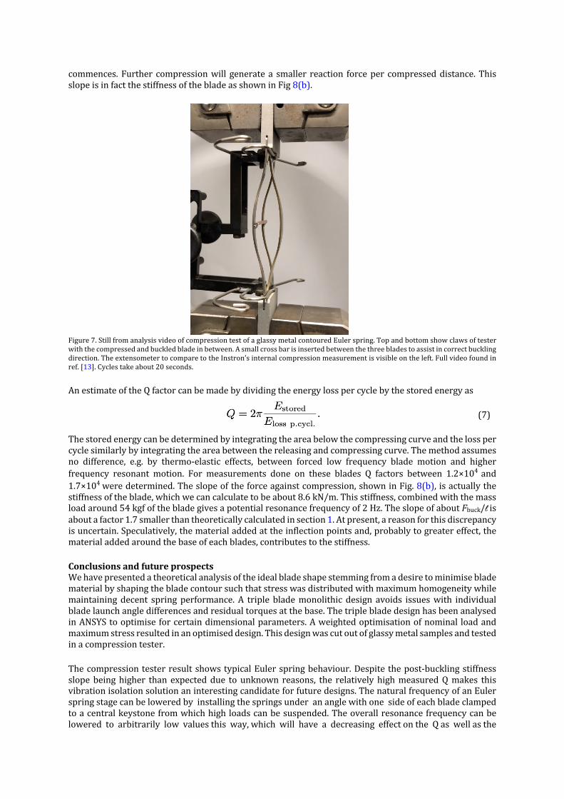
DifferentvaluesfornwereusedintheFEAassisteddesignoptimisation,namely0.5<n<4instepsof0.25.ResultsofthisanalysisareshowninFig.6.Obviously,ndeterminestheweightthebladedesignerassignstothenominalloadorlowpeak(vonMises)stressinthebladeforahighorlowvalueofn,respectively.Asdiscussed above, increasingV1will increase thenominal blade load.Thiswill however reduceV2andincreasestressinthatarea,wherethetwoadjacentbladesbuckleoutofplaneinoppositedirection.
Fig.6(a)showshowthenominalloadincreaseswhenincreasingthepowernintheoptimisationprocess.ThemaximumstressalsoincreasesshowninFig.6(b)asthesinglebladeprofilewidthincreasesandthesplinecurve(nearthereddotinFig.4(a))issharperresultinginthestressdistributiontobecomelessandlesshomogeneous.Athirdorderpolynomialfitwasperformedtocapturetheoveralltrendineachplot.Fig.6(c)showsthemaximumloadvsmaximumstress,usingthe3rdorderpolynomialfitsofFig.6(a)andFig.6(b)(solidredlines).Thereddotshowsthevaluesforn=2wherewedecidedbyeyetheoptimalvalueforn is, as further increasingnwouldonlymarginally increase loadatanever increasingpriceon themaximumstress.
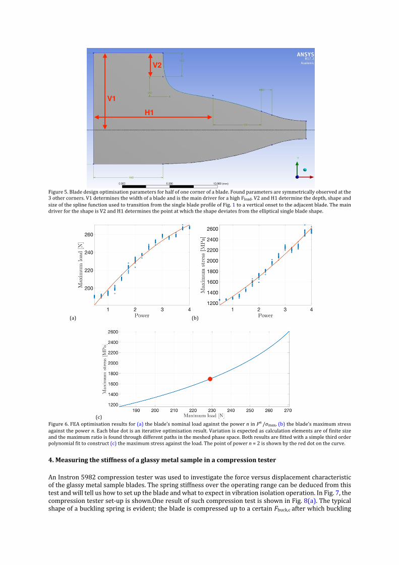
Figure5.Bladedesignoptimisationparametersforhalfofonecornerofablade.Foundparametersaresymmetricallyobservedatthe3othercorners.V1determinesthewidthofabladeandisthemaindriverforahighFload.V2andH1determinethedepth,shapeandsizeofthesplinefunctionusedtotransitionfromthesinglebladeprofileofFig.1toaverticalonsettotheadjacentblade.ThemaindriverfortheshapeisV2andH1determinesthepointatwhichtheshapedeviatesfromtheellipticalsinglebladeshape.
(a) (b)
(c) Figure6.FEAoptimisationresultsfor(a)theblade’snominalloadagainstthepowerninFn/σmax,(b)theblade’smaximumstressagainstthepowern.Eachbluedotisaniterativeoptimisationresult.Variationisexpectedascalculationelementsareoffinitesizeandthemaximumratioisfoundthroughdifferentpathsinthemeshedphasespace.Bothresultsarefittedwithasimplethirdorderpolynomialfittoconstruct(c)themaximumstressagainsttheload.Thepointofpowern=2isshownbythereddotonthecurve.
4.Measuringthestiffnessofaglassymetalsampleinacompressiontester
AnInstron5982compressiontesterwasusedtoinvestigatetheforceversusdisplacementcharacteristicoftheglassymetalsampleblades.Thespringstiffnessovertheoperatingrangecanbededucedfromthistestandwilltellushowtosetupthebladeandwhattoexpectinvibrationisolationoperation.InFig.7,thecompressiontesterset-upisshown.OneresultofsuchcompressiontestisshowninFig.8(a).Thetypicalshapeofabucklingspringisevident;thebladeiscompresseduptoacertainFbuck,cafterwhichbuckling
commences.Further compressionwill generatea smaller reaction forceper compresseddistance.ThisslopeisinfactthestiffnessofthebladeasshowninFig8(b).
Figure7.StillfromanalysisvideoofcompressiontestofaglassymetalcontouredEulerspring.Topandbottomshowclawsoftesterwiththecompressedandbuckledbladeinbetween.Asmallcrossbarisinsertedbetweenthethreebladestoassistincorrectbucklingdirection.TheextensometertocomparetotheInstron’sinternalcompressionmeasurementisvisibleontheleft.Fullvideofoundinref.[13].Cyclestakeabout20seconds.
AnestimateoftheQfactorcanbemadebydividingtheenergylosspercyclebythestoredenergyas
(7)
Thestoredenergycanbedeterminedbyintegratingtheareabelowthecompressingcurveandthelosspercyclesimilarlybyintegratingtheareabetweenthereleasingandcompressingcurve.Themethodassumesno difference, e.g. by thermo-elastic effects, between forced low frequency blade motion and higherfrequency resonant motion. For measurements done on these blades Q factors between 1.2×10⁴ and1.7×104weredetermined.Theslopeoftheforceagainstcompression,showninFig.8(b),isactuallythestiffnessoftheblade,whichwecancalculatetobeabout8.6kN/m.Thisstiffness,combinedwiththemassloadaround54kgfofthebladegivesapotentialresonancefrequencyof2Hz.TheslopeofaboutFbuck/lisaboutafactor1.7smallerthantheoreticallycalculatedinsection1.Atpresent,areasonforthisdiscrepancyisuncertain.Speculatively,thematerialaddedattheinflectionpointsand,probablytogreatereffect,thematerialaddedaroundthebaseofeachblades,contributestothestiffness.
Conclusionsandfutureprospects Wehavepresentedatheoreticalanalysisoftheidealbladeshapestemmingfromadesiretominimisebladematerialbyshapingthebladecontoursuchthatstresswasdistributedwithmaximumhomogeneitywhilemaintainingdecent springperformance.A triple blademonolithic design avoids issueswith individualbladelaunchangledifferencesandresidualtorquesatthebase.ThetriplebladedesignhasbeenanalysedinANSYStooptimiseforcertaindimensionalparameters.Aweightedoptimisationofnominal loadandmaximumstressresultedinanoptimiseddesign.Thisdesignwascutoutofglassymetalsamplesandtestedinacompressiontester.
ThecompressiontesterresultshowstypicalEulerspringbehaviour.Despitethepost-bucklingstiffnessslopebeinghigher than expecteddue tounknown reasons, the relativelyhighmeasuredQmakes thisvibrationisolationsolutionaninterestingcandidateforfuturedesigns.ThenaturalfrequencyofanEulerspringstagecanbeloweredbyinstallingthespringsunderananglewithonesideofeachbladeclampedtoacentralkeystonefromwhichhighloadscanbesuspended.Theoverallresonancefrequencycanbeloweredtoarbitrarilylowvaluesthisway,whichwillhaveadecreasingeffectontheQaswellasthe

(a) (b)
Figure8.Compressiontestresultofthefirst,fourthandninthcycleofa10-cycle-longmeasurementonaglassymetalmonolithiccontouredEulerspring.Panel(a)showsthetypicalbucklingcurve.Thenon-smoothrisetowardsthesmoothbucklingcurvecouldbesettingoftheextensometerlegsuponcompressionorrealhystericbehaviorofthematerialuponcompression.Panel(b)zoomsinonthespringbehavioroftheblade.Theslopeofthebuckledbladethatrepresentsthestiffnessofthespringisillunderstood-itsmagnitudeisaboutFbuck/l.
dynamicrangeofthesystem.AthreeEulerspringinatriangularformationisproposed.Atrialwithjusttwospringsis firstpursued[14].Thesecompact,highquality, futuresystemscanbeusedforvibrationisolation systems of future GW detectors, such as Einstein Telescope [15] or Cosmic Explorer [16].Additionally,springsinsuchconfigurationcanalsobeusedinproofmasssuspensionsforlowfrequency,highquality,verticalinertialsensors.
Acknowledgements Thisworkwas fundedby theAustralianResearchCouncil (ARC)CentreofExcellence forGravitationalWave Discovery OzGrav under grant CE170100004. We would like to thank Andrew Sunderland,Alessandro Bertolini, David Blair, Bram Slagmolen and Joshua McCann for useful discussions andcomments.Additionally,wewould like toacknowledgecontributions fromstudentsLindsayWoodandWenjingZhengearlyon.TheauthorsalsowishtothanktheworkshoptechniciansKenFieldandSteveKey.
References[1]B.P.Abbottetal.,”ObservationofGravitationalWavesfromaBinaryBlackHoleMerger”,Phys.Rev.Lett.,vol.116,pp.061102(2016) [2]B.P.Abbottetal.,”GW170817:ObservationofGravitationalWavesfromaBinaryNeutronStarInspiral”,Phys.Rev.Lett.,vol.119,pp.161101(2017) [3]B.P.Abbottetal.,”Multi-messengerObservationsofaBinaryNeutronStarMerger”,ApJL,484(2),L12(2017) [4]J.C.Dumasetal.,“Testingofamulti-stagelow-frequencyisolatorusingEulerspringandself-dampedpendulums”,Class.Quant.Grav.,21(5),pp.S965–S971(2004) [5]E.Chinetal.,“AIGOHighPerformanceCompactVibrationIsolationSystem”,JournalofPhysics:ConferenceSeries,32,pp.111–116(2006) [6]F.Acerneseetal.,”AdvancedVirgo:asecond-generationinterferometricgravitationalwavedetector”,Class.Quant.Grav.32(2),pp024001(2014) [7]T.Akutsuetal.,”ConstructionofKAGRA:anUndergroundGravitationalWaveObservatory”,ProgressofTheoreticalandExperimentalPhysics,Volume2018,Issue1,013F01(2018) [8]M.Beccariaetal.,”ExtendingtheVIRGOgravitationalwavedetectionbanddowntoafewHz:metalbladespringsandmagneticantisprings”,Nuc.Instrum.andMeth.A,Vol.394,pp.397–408(1997) [9]G.Cellaetal.,”Monolithicgeometricanti-springblades”,Nucl.Instr.andMethodsinPhys.A540(2),pp.502-519(2005) [10]S.Markaetal.,“AnatomyofTAMASASseismicattenuationsystem,”Class.Quant.Grav.,vol.19,pp.1605–1614(2002) [11]J.Winterfloodetal.,“UsingEulerbucklingspringsforvibrationisolation”,Class.Quant.Gravity19(7),pp.1639–1645(2002) [12]J.Winterfloodetal.,”HighperformancevibrationisolationusingspringsinEulercolumnbucklingmode”,Phys.Lett.A,Vol.300(2–3),pp.122-130(2002) [13]EulerspringsatUWA,YouTube(2019)[14]J.J.McCannetal.”Suspensionsand(rotational)accelerometersatOzGrav’sUWAnode”,DCCnumberG1901603,LVKAutumnmeeting(2019)[15]M.Abernathyetal.,”EinsteingravitationalwaveTelescopeconceptualdesignstudy”,Tech.Rep.ET-0106C-10,http://www.et-gw.eu/index.php/etdsdocument(2011)[16]B.P.Abbotetal.,”ExploringtheSensitivityofNextGenerationGravitationalWaveDetectors”,Class.Quant.Grav.34,pp.044001(2017)[17]J.Winterflood,T.A.BarberandD.G.Blair,”MathematicalAnalysisofanEulerSpringVibrationIsolator”,Phys.Lett.A300,Iss.2–3(2002)
Recommended