karneluik.com // Networking // Multicasting in IOS, IOS XE, IOS XR for IPv4 and IPv6
Copyright ©2016 Anton Karneliuk. All rights reserved 1
Multicasting in IOS, IOS XE, IOS XR for IPv4 and IPv6
Disclaimer. I don’t pretend to cover everything about the protocols or mechanisms that we
have in multicasting. I just explain what we use nowadays, why we use it, how it works and how to
configure it.
Introduction
I’ve started to write this article with the idea to show which bugs I’ve found while studying
multicast topics at IOS XR (particularly IOS XRv). But during the process of writing, it turned into a
short overview of multicasting at different Cisco platforms. About three months ago I successfully
passed CCIE RS lab exam and finally became CCIE Routing and Switching #49412. From my
perspective a person can either develop further or degrade. It’s impossible to stay forever with the
same knowledge at the same place. Ok, maybe it’s possible, but for sure it makes no sense. That’s
why I’ve decided to extend my knowledge of IOS and IOS XE to IOS XR. Previously I have had some
experience with this platform, but never in the multicast field. Also I think that it can be a good
starting point for the future, if I decide to get CCIE Service Providers. So, let’s go.
The multicasting technology isn’t something in our days. I could even say more, there is a lot
of multicast traffic in your network right now, of which you might be not aware. Many network
protocols use multicast transport for their operations. For example, there are OSPF, ISIS, EIGRP, SPT,
LDP and many others. Multicasting has been already on the market for a long time. However the
importance of the technology becomes more and more important every day, as the interactive
application with its big amount of voice and video tends to dominate in the Internet and local
networks. The basic idea is pretty straightforward:
If there are many clients that want to receive the same content simultaneously, there is no
necessity to establish a dedicated session with each one and unicast content to each one. The server
sends just one multicast stream in the network instead, and the network itself will replicate and
deliver the traffic to the necessary destinations.
The overall architecture of multicasting can be split into three main points:
1) How to deliver multicast traffic in a local segment of the network (basically in the VLAN).
2) How to deliver multicast traffic through the routed network but in the border of the single
Autonomous system.
3) How to deliver multicast traffic on the Internet’s scale between different autonomous
systems.
In this article I’ll focus on the first two points. Though I don’t like theory very much and
would eager to jump directly to the configuration and validation section, I have to provide a short
overview in order for you to have an overall understanding of multicasting, which is useful for further
configuring and troubleshooting.
Layer 2 multicast destination addresses
In the local segment the transmission of the traffic is done based on the Layer 2 header.
Nowadays Ethernet (IEEE 802.3 set of standards) is the only technology that is used in the wired part
of LAN. In the wireless part of LAN (WLAN) we use IEEE 802.11 set of standards. They have a little bit
different framing due to some nature of wireless operation: less reliability and half-duplex traffic
pattern in the one RF channel. But both Ethernet and WLAN standards use the same form of physical
karneluik.com // Networking // Multicasting in IOS, IOS XE, IOS XR for IPv4 and IPv6
Copyright ©2016 Anton Karneliuk. All rights reserved 2
layer addressing – MAC address. It consists of 48 bits that are split into two parts. The first 24 bits
represent the vendor of the equipment and are managed by IEEE registration authority. The second
24 bits are generated by vendor and are assigned to the certain device (NIC – network interface
card). Coupling together these two parts we get a global unique MAC address. Or at least it must be
so, as almost all the operation systems allow you to manually configure the MAC address instead of
the one that’s burned in the hardware. Let’s have a deeper look at the format of MAC address.
Usually it’s represented as a hexadecimal number 32-10-B3-E9-A9-D2.
Let’s translate it in the binary form, as we need it for understanding how multicast MAC
address is identified:
00110010-00010000-10110011-11101001-10101001-11010010
The second least significant bit in the first octet, which is the green one at my picture, is U/L
bit, which shows whether this MAC is configured locally (value “1”) or unique in the world (value
“0”).
We are mostly interested in the least significant bit in the first octet, which is red on my
picture. It’s I/G bit, where “I” stands for individual MAC and has a value of “0”, and “G” stands for
group MAC address and has a value of “1”, which is used for broadcast and multicast. Here we come
to the first important point about addressing in multicasting. Multicast MAC address always has that
bit set to “1”. Actually, the most popular multicast MAC addresses that we can see have the following
first 24 bits : 01-00-5E or 01-80-C2. Now we are going to explain the Layer 3 (IP) addressing and
multicasting and then come back to MAC addresses to show how they are mapped.
Layer 3 multicast destination addresses in IPv4
In IPv4 world the multicast IP addresses are represented by class D IP networks that are
covered by 224.0.0.0/8 range. We can consider each IP address from this range as a TV or radio
channel. It means that everyone who is listening to this IP will receive the same content. As it usually
happens with IP addressing, there are some IP subranges that have specific meaning and shouldn’t
be used for user traffic, and others that should:
IP Range Task
224.0.0.0/24 it’s used for network protocol to communicate in
a local segment; it isn’t routed
224.0.1.0/24 it’s used for network protocol to communicate in
the internetwork, so it’s routed
232.0.0.0/8 it’s used for source specific multicast (will be
described later)
239.0.0.0/8 it’s used for user application in enterprise
borders.
All the ranges are defined in RFC 5771, so you could look there for the more detailed
information [a]. In our article I’ll refer mainly to the last range, meaning to 239.0.0.0/8.
Coupling together Layer 2 and Layer 3 destination addresses
Now we know how multicast IPv4 addresses look like and what should be set in MAC
address. Let’s couple them together. The rule for mapping IPv4 multicast address to MAC multicast
address is the following:
karneluik.com // Networking // Multicasting in IOS, IOS XE, IOS XR for IPv4 and IPv6
Copyright ©2016 Anton Karneliuk. All rights reserved 3
Take the 23 least significant bits in IPv4 multicast address and map them to the least
significant 23 bits in MAC address. The 24-th least significant bit will be always “0”. Then append the
resulting number by 01-00-5E in hexadecimal.
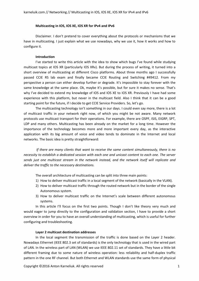
Here is just a short example for you to understand it better. We send multicast data stream
to the group 239.123.123.123. Let’s convert IP to binary view:
11101111.01111011.01111011.01111011
Looks good, now let’s take the least significant 23 bits that shown at my picture as red and
finalize mapping to MAC Address according to the rule above:
0 + 1111011.01111011.01111011 -> 7B-7B-7B
At the end we just attach “01-00-5E” before our number and get the L2 multicast address 01-
00-5E-7B-7B-7B. To this MAC address will be the traffic sent if we send packets to 239.123.123.123. If
we look a bit deeper, we could see that there is a potential oversubscription (32:1) when we map
IPv4 to MAC. Actually IPs 239.123.123.123, 224.123.123.123 and even 239.251.123.123 are mapped
to the only one MAC 01-00-5E-7B-7B-7B. So it’s stated not to be a problem as a probability of such
overlapping is quite low. Though if it happens, the traffic will be taken to the processing but then it’ll
be dropped. The CPU/Memory capacity is considered to be very high comparing to the probable
amount of traffic.
IPv4 multicast packet
Layer 3 multicast addresses in IPv6 and its mapping
Now let’s look into the IPv6 world and how these IP addresses are mapped to MAC
addresses. Actually it's also easy, and from my understanding easier than in IPv4, though it isn’t so
popular and well described. IPv6 address itself is much longer than IPv4 (128 bits against 32 bits).
And the probability of oversubscription is also much higher. That’s why we copy THE 32 least
significant bits in IPv6 multicast address to MAC address. We can state the rule as:
Take the 32 least significant bits in IPv6 multicast address and copy them to multicast MAC
address. Then append them by 33-33 in hexadecimal.
In general IPv6 multicast addresses are in the range of ff::/8. There are also some specific
subranges as in IPv4, and you can find some references at the end of the article [b]. For user’s
application we usually use IPv6 addresses, which start with ff05::/16 or ff08::/16.
karneluik.com // Networking // Multicasting in IOS, IOS XE, IOS XR for IPv4 and IPv6
Copyright ©2016 Anton Karneliuk. All rights reserved 4
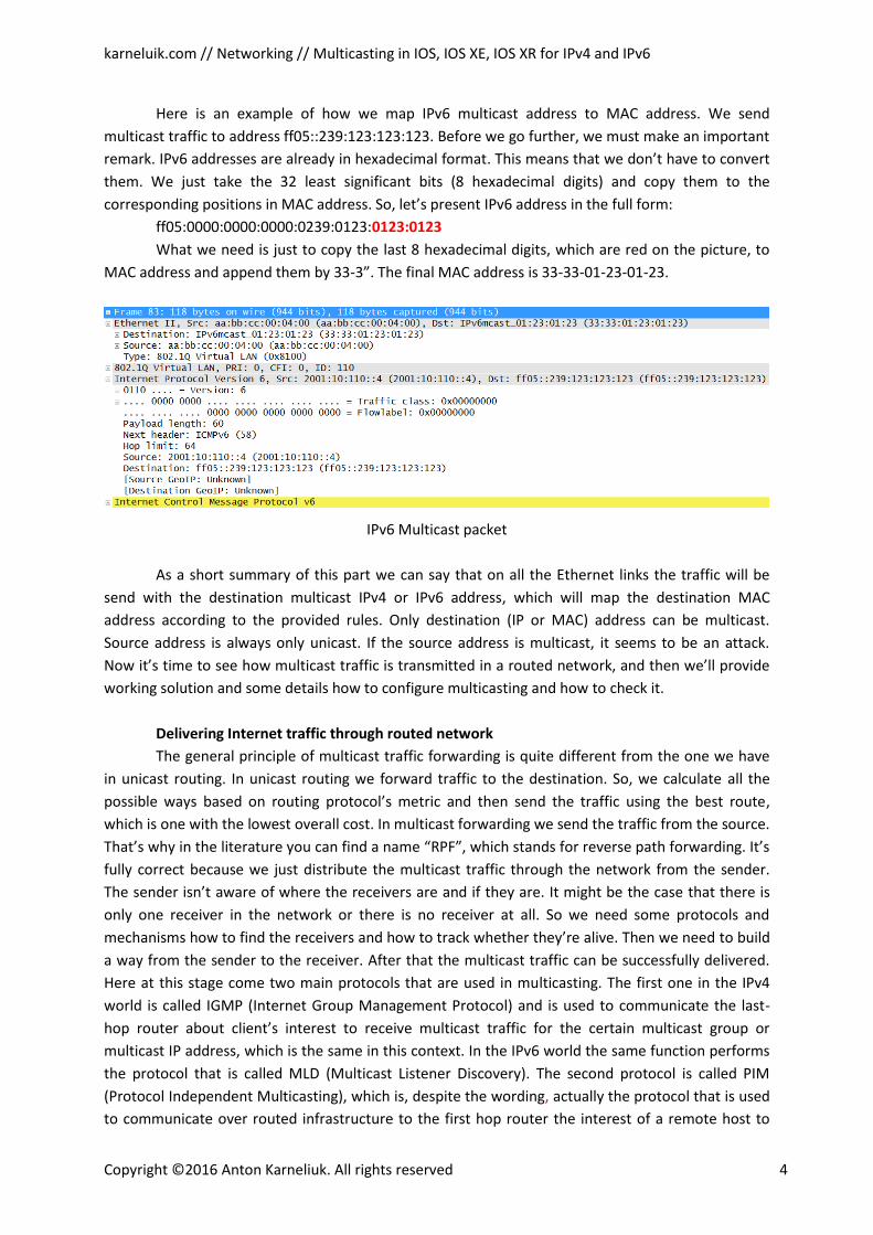
Here is an example of how we map IPv6 multicast address to MAC address. We send
multicast traffic to address ff05::239:123:123:123. Before we go further, we must make an important
remark. IPv6 addresses are already in hexadecimal format. This means that we don’t have to convert
them. We just take the 32 least significant bits (8 hexadecimal digits) and copy them to the
corresponding positions in MAC address. So, let’s present IPv6 address in the full form:
ff05:0000:0000:0000:0239:0123:0123:0123
What we need is just to copy the last 8 hexadecimal digits, which are red on the picture, to
MAC address and append them by 33-3”. The final MAC address is 33-33-01-23-01-23.
IPv6 Multicast packet
As a short summary of this part we can say that on all the Ethernet links the traffic will be
send with the destination multicast IPv4 or IPv6 address, which will map the destination MAC
address according to the provided rules. Only destination (IP or MAC) address can be multicast.
Source address is always only unicast. If the source address is multicast, it seems to be an attack.
Now it’s time to see how multicast traffic is transmitted in a routed network, and then we’ll provide
working solution and some details how to configure multicasting and how to check it.
Delivering Internet traffic through routed network
The general principle of multicast traffic forwarding is quite different from the one we have
in unicast routing. In unicast routing we forward traffic to the destination. So, we calculate all the
possible ways based on routing protocol’s metric and then send the traffic using the best route,
which is one with the lowest overall cost. In multicast forwarding we send the traffic from the source.
That’s why in the literature you can find a name “RPF”, which stands for reverse path forwarding. It’s
fully correct because we just distribute the multicast traffic through the network from the sender.
The sender isn’t aware of where the receivers are and if they are. It might be the case that there is
only one receiver in the network or there is no receiver at all. So we need some protocols and
mechanisms how to find the receivers and how to track whether they’re alive. Then we need to build
a way from the sender to the receiver. After that the multicast traffic can be successfully delivered.
Here at this stage come two main protocols that are used in multicasting. The first one in the IPv4
world is called IGMP (Internet Group Management Protocol) and is used to communicate the last-
hop router about client’s interest to receive multicast traffic for the certain multicast group or
multicast IP address, which is the same in this context. In the IPv6 world the same function performs
the protocol that is called MLD (Multicast Listener Discovery). The second protocol is called PIM
(Protocol Independent Multicasting), which is, despite the wording, actually the protocol that is used
to communicate over routed infrastructure to the first hop router the interest of a remote host to

karneluik.com // Networking // Multicasting in IOS, IOS XE, IOS XR for IPv4 and IPv6
Copyright ©2016 Anton Karneliuk. All rights reserved 5
receive the traffic. This protocol exists both in IPv4 and IPv6 world. Here is the sample picture where
the areas of usage of IGMP and PIM are shown.
The areas of multicast protocols usage
Now we’ll explain a bit how both these protocols together help you to deliver multicast
content from the sender to the receivers.
IGMP and MLD – “last-mile” solution
As we already told, IGMP is used to communicate the client’s interest from the receiver to
the last hop router, which is R3 referring to our topology. There are two options to realize it. The first
one is by sending the regular queries (IGMP Query) by R3 on the LAN segment to the multicast IP
address 224.0.0.1, which represents all the hosts on the local segment. If the receiver wants to get
some traffic, it will answer to multicast IP 224.0.0.2, which represent all multicast-capable routers on
a local segment. In the answer the receiver will include the multicast IP, for example
239.123.123.123, for which it wants to receive traffic. Such answer is called IGMP Report,
contemporary to IGMP Query sent by R3. Remember that we have mentioned the whole
224.0.0.0/24 range as the one that is used for network control and that isn’t routed. Actually this
mechanism is also used for tracking whether there is any host that wants to receive. If nobody
answers, then the router will stop multicasting on that segment.
The second option of how the receiver can indicate its interest is the explicit request. If you
launch any application for receiving multicast traffic and choose the actual channel represented by
multicast IP, your PC (the Receiver in the our topology) will immediately send IGMP Report to R3. The
same mechanism is also used to show the R3 that you are not interested anymore in receiving
multicast traffic. After that R3 will check whether there is anyone else on the local segment who
wants to receive the traffic. For that R3 sends the group-specific query to the multicast IP address of
the group that is 239.123.123.123 in our case. If no one answers, R3 will stop forwarding multicast on
a local subnet.
We have described here overall operation of IGMPv2. But “v2” means that it must be other
versions of this protocol. Well, we don’t describe the operation of IGMPv1 as it’s quite old and can be
karneluik.com // Networking // Multicasting in IOS, IOS XE, IOS XR for IPv4 and IPv6
Copyright ©2016 Anton Karneliuk. All rights reserved 6
considered as obsolete. On the other hand, the most actual version of IGMP is the 3rd. It differs
from the IGMPv2 in that it supports the option to include the IP addresses of the source from which
the client wants to receive the multicast traffic. Such option is critical both for source-specific
multicast (SSM) and for security. SSM will be explained further. Now we’ll explain a bit the security
issue. In IGMPv2 there is no option to control which is the source of the traffic. Such situation
provides the possibility to make a DoS or DDoS attack on the receiver, during which the client won’t
receive the legitimate traffic. Moreover the source provides a kind of filtering to limit the possibility
of attack. Also IGMPv3 supports explicit hosts tracking to improve the quality of delivering the
multicast traffic on the end segment. Destination IP address for IGMPv3 queries is the same as for
IGMPv2 224.0.0.1, but the IP for IGMPv3 Reports is 224.0.0.22. [c] The latest versions have the
compatibility with the lower ones.
By default in Cisco IOS and IOS XE IGMPv2 is used and in Cisco IOS XR the default version is
IGMPv3. But you change it in both.
Now let’s see how the same task is resolved in the IPv6 world, where we use MLD instead of
IGMP. There are two versions of this protocol. MLDv1 is based on IGMPv2. Actually it’s stated in the
RFC itself [d]. For us it means that the functionality and the logic behind it is the same as it’s in
IGMPv2. The General query is sent to multicast destination IP ff02::1. In IPv6 the range ff02::/16 is
used for the same purposes as the range 224.0.0.0/8 in IPv4, so to say, for local network control. But
contemporary to IGMPv2, MLD Reports are sent to group-specific address as well as a group-specific
Queries. To communicate that the host doesn’t want to receive multicast IPv6 traffic, the MLD Done
message is used, which is sent to multicast address of all multicast-capable routers ff02::2. The
protocol timers are a bit different, but we think it is neither useful nor interesting to provide here all
this stuff. You can always refer to Cisco official command reference guide to the latest information.
[e] MLDv2 is an IPv6 version of IGMPv3, meaning that is necessary for SSM, explicit host tracking and
improvement of security. Destination IP address for Report messages is ff02::16. Others are the
same.
There is one option that is used to improve multicast efficiency in local segment that is called
IGMP snooping. The idea behind this feature is to track on the switch the ports that are interested in
a certain multicast traffic and then to send L2 multicast only to that ports. This is done by analyzing
IGMP Reports from the clients and binding destination multicast MAC address to the ports that have
received the corresponding IGMP Report.
Well, we already know how the remote host can say to its router that he wants to receive
multicast. Now it’s time to see how this info is distributed over routed infrastructure and how the
multicast data is transmitted from the sender to the receiver.
PIM – “core” solution
The name PIM may look quite strange at a first glance. Really, we say that it’s protocol, it
uses PIM Hello messages to establish the adjacency with other PIM-speaking neighbors like OSPF or
EIGRP does, though the wording says us “protocol independent multicast”. Well, such name PIM has
due to its neutrality to unicast routing protocol or IGP. It means that PIM doesn’t care which IGP you
use in your network. It can be OSPF, ISIS, EIGRP and so on. And even static routes can be used. PIM
uses its own set of messages, but it uses underlying IGP to find the best way to the sender from the
receiver. This point is crucial. We’ve already said that multicast forwarding is RPF, meaning that it’s
karneluik.com // Networking // Multicasting in IOS, IOS XE, IOS XR for IPv4 and IPv6
Copyright ©2016 Anton Karneliuk. All rights reserved 7
done from the sender rather than to the destination. But to be efficient, RPF must have some
mechanisms of loop prevention. Such mechanism is called RPF-check and works as follows:
The router replicates multicast traffic out its interfaces only if it receives the multicast traffic
on the interfaces which is also used to get to the sender. It means, that in unicasting routing table we
must have a route to the sender that point out that interface. If multicast traffic is received at another
interface, it’ll be dropped.
Looking in our topology, we can say that such interface at R3 will be in the direction of R1.
Also the same interface is used to signal to upstream router that we have clients who are interested
in receiving multicast traffic for the certain multicast group (IP address). When the clients don’t want
to receive the multicast traffic anymore, this mechanism will also be used to stop receiving multicast
traffic from upstream router. At the end of the day we’ll have a tree starting from the sender and
ending at the receivers. Such Tree is called SPT (shortest path tree), because it uses the shortest path
from each receiver to the sender. SPT is usually presented with a pair (S,G), where “S” stands for
unicast IP address of the sender and “G” is the destination multicast address of the group. There is
also another tree that is called rendezvous point three (RPT) or shared tree and is represented with a
pair (*,G), where “*” means any source. The RPT will be explained in the next section. It’s very rough
overview of PIM, but the core functionality and tasks are clear.
Historically there were two main versions, or more correctly to say modes, of PIM: dense
mode (PIM-DM) and sparse mode (PIM-SM). In PIM-DM it’s considered that there are a lot of
receivers in the network. That’s why the multicast traffic is distributed to all the routers in the
network and then they prune themselves if they don’t have any interested receivers. Academically
speaking we build SPT from the beginning and then cut it down.
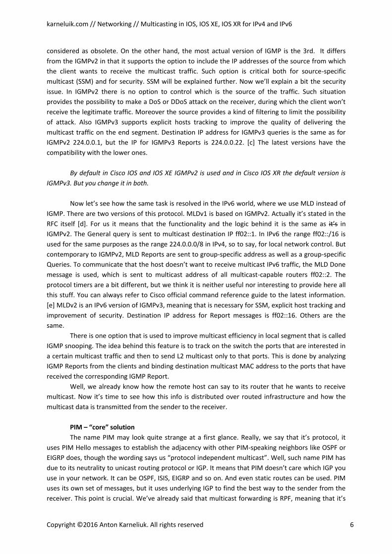
PIM-DM traffic flow
So, let’s take a look on what’s going on here:
1) At the first step the IGMP Report is received by R3 from the Receiver. This report contains
information that the client wants to receive multicast stream for the group
239.123.123.123. In PIM-DM we don’t send any PIM messages further as we don’t know
where the sender is.
2) At the second step the sender starts to send multicast traffic which is then distributed
throughout the network, so it reaches the receiver as well. At the end of this step the
multicast data from R2 to R3 doesn’t pass the RPF check at R3 as the unicast route at R3
to the sender is through R1.
karneluik.com // Networking // Multicasting in IOS, IOS XE, IOS XR for IPv4 and IPv6
Copyright ©2016 Anton Karneliuk. All rights reserved 8
3) At the third step R3 tells R2 to stop sending the traffic using PIM Prune message due to
RPF check failure. As R2 doesn’t have any clients, it also sends PIM Prune message to R1.
Such approach is considered being inefficient, and now PIM-DM isn’t used anymore. To stress
this fact we say that there is no PIM-DM for IPv6 at Cisco devices at all, and at Cisco IOS XR you even
don’t have possibility to configure PIM-DM for IPv4.
What is widely used nowadays and what is recommended to use is PIM-SM. In PIM-SM it’s
considered that there are few receivers in the network, so we don’t have to spam the traffic through
the whole network. The core concept of the PIM-SP consists of the introducing the RP (rendezvous
point), which is simply a router, where the traffic from the sender and the interest from clients are
met. In this case two separate RPF checks are made. From the receivers the RPF-check is made to the
IP address of the RP what is usually a loopback of the router, and from the RP the RPF-check is made
to the IP address of the sender. Then there are two possible way, what can happen.
It may look strange for you, but I’ll start with the second option, because it’s easier to explain
it. This option is called PIM-bidir or bidirectional PIM. In this case we configure a certain range, for
example 239.255.0.0/16, that is used only for bidirectional multicast traffic forwarding. For
bidirectional PIM no SPT can be build and all the traffic will always flow through RP. Such approach is
useful in many-to-many applications. For example, they are multipoint videoconferencing or stock
exchange ticketing applications.
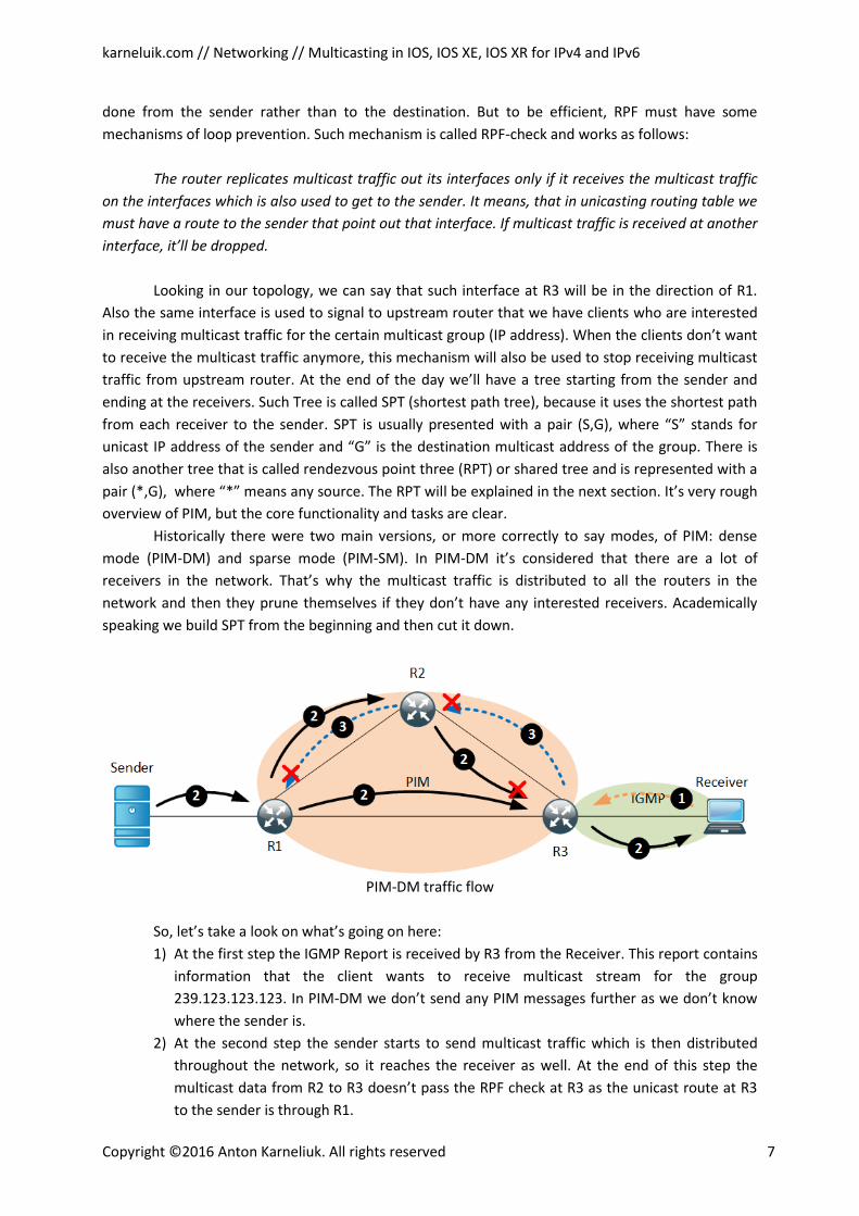
PIM-bidir traffic flow
The operation of the PIM-bidir can be explained as follows:
1) The certain range of multicast IP addresses is configured at the RP and then is sent
through the network. For example, it’s 239.255.0.0/18. All routers have a group (*,
239.255.0.0/18) that points to the IP address of the RP.
2) Then client reports that it wants to receive traffic for a certain group, for example it’s
239.255.123.123.
3) R3 sends PIM Join message to R2 for group (*, 239.255.123.123). A separate (*, G) RPT is
built only for this destination multicast IP address and only from R2 to R3.
4) The sender starts to multicast data. In the part of the network between ingress router and
RP the traffic is sent to the RP according the RPT for the group (*, 239.255.0.0/18). From
the RP the traffic is sent down to the receiver using RPF for the group (*,
239.255.123.123).
karneluik.com // Networking // Multicasting in IOS, IOS XE, IOS XR for IPv4 and IPv6
Copyright ©2016 Anton Karneliuk. All rights reserved 9
In PIM-bidir scenario the placement of the RP is very important as we should consider all
possible traffic flows and should avoid not optimal one.
Now let’s go back to the first option which is the classical PIM-SM approach, using which the
RPT will be switched to the SPT if there is any traffic sender. It means that if there is any receiver and
no senders only RPT from clients to RP will be built. It’s very important point, because the ingress
router where the sender is attached might be not on the path. It means that this ingress router will
be unaware of the presence of multicast group. Or there can be another situation when we have a
sender and no receivers. To solve such problems in PIM-SM the incoming multicast traffic at the
beginning is tunneled in PIM Registration messages from the ingress router to the RP. If there is no
receiver, the RP will answer with PIM Register-Stop message to ingress router to stop sending traffic
for some time. If there is a client for the multicast stream, meaning that RP has already entry for the
group (*, G), the traffic will be forwarded to the client according to the RPT, and the RP itself will
build the SPT (S,G) to the sender. When the clients receive first actual multicast data, the last hop
router initiates a building of the SPT (S,G) to the unicast IP address of the sender. It can be situations
that the RP is not on the actual path between the sender and the receivers. It’s actually normal for
classical PIM-SM mode as the RP is only a registration point which is used for setup of the multicast
streaming. During multicast streaming the RP keeps track of the actual status of the group (S,G) to
allow new clients to be quickly added to that stream and to receive multicast content.
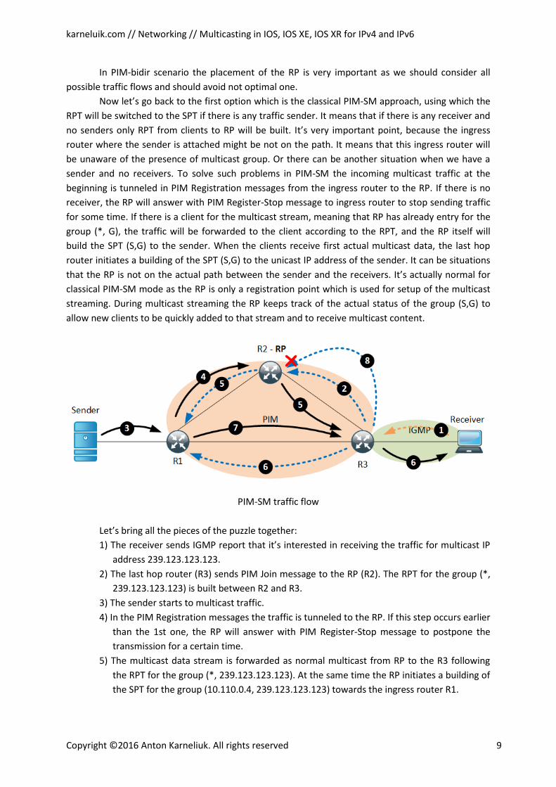
PIM-SM traffic flow
Let’s bring all the pieces of the puzzle together:
1) The receiver sends IGMP report that it’s interested in receiving the traffic for multicast IP
address 239.123.123.123.
2) The last hop router (R3) sends PIM Join message to the RP (R2). The RPT for the group (*,
239.123.123.123) is built between R2 and R3.
3) The sender starts to multicast traffic.
4) In the PIM Registration messages the traffic is tunneled to the RP. If this step occurs earlier
than the 1st one, the RP will answer with PIM Register-Stop message to postpone the
transmission for a certain time.
5) The multicast data stream is forwarded as normal multicast from RP to the R3 following
the RPT for the group (*, 239.123.123.123). At the same time the RP initiates a building of
the SPT for the group (10.110.0.4, 239.123.123.123) towards the ingress router R1.
karneluik.com // Networking // Multicasting in IOS, IOS XE, IOS XR for IPv4 and IPv6
Copyright ©2016 Anton Karneliuk. All rights reserved 10
6) At this step also two simultaneous actions take place. The multicast data is sent to the
receiver and the last hop router build the SPT for the group (10.110.0.4, 239.123.123.123)
to R1.
7) The multicast data is streamed from R1 to R3 alongside the built SPT.
8) R3 sends to R2 the message that it doesn’t want to receive the multicast traffic from R2 as
it receives it through R1.
If we think about the algorithm above, we can see that despite some administrative
overhead the PIM-SM helps save a bandwidth in the network and reduce the amount of unnecessary
multicast traffic. Completely the same processes as described here for IPv4 for PIM-SM and PIM-bidir
exist in IPv6 world. We just replace IGMP with MLD, because PIM for IPv6 is also used.
Options for rendezvous point (RP)
Now let’s talk a little bit about the RP itself. Actually there are some options how it can be
configured and communicated through the network. Some options are specific for IPv4 or IPv6, so
we’ll point out such difference. But what is common for all options is that you should configure the
loopback interface of the router as the IP address for RP. It guarantees the availability of this address
regardless of any failures on the physical interfaces of the RP.
The first one is called Static RP. It’s the easiest and the most unreliable way how to configure
RP. You just tell all you routers in the network that the RP has a certain IP address, and all multicast
traffic will be forward accordingly. But if the RP is down, you have to reconfigure all the routers, just
as you do this with static routes for example. This option can be used both for IPv4 and for IPv6.
The second option is called BSR or Boot Strap Router. We have two main components in BSR
installation. The first one is the BSR itself which is actually a mapping agent for the RPs (we can have
many RPs here). It collects information about a candidate RPs and sends it throughout the network
using PIM and its multicast IP address 224.0.0.13 for IPv4 and ff02::13 for IPv6. You can configure
many routers as the BSR but only one will be used in the certain moment of time. So, you have a
possibility to implement a kind of redundancy. The wording “candidate RP” means that it isn’t
necessary that the router well be the active RP. As with the BSR there might be many routers
configured as the RP. There are some hashing algorithms on a backstage which regulate whether the
router is or isn’t the RP for a whole multicast range or for the certain group. This hash function
provides the opportunity to share the multicasting load as well. In the certain moment of time there
is only one RP for the certain group, but different groups can be mapped to the different RPs. Each
candidate RP sends its presence and configuration to the unicast IP address of the BSR. Then the BSR
distributes this information throughout the network. The BSR can be configured both for IPv4 and for
IPv6. It’s the most recommended way of multicast configuration, because it’s a standard, meaning
that you can use it in multivendor environment.
The third option is Auto-RP. It’s the Cisco-proprietary feature that exists only in IPv4 world. It
was invented before the BSR algorithm that’s why it was the first solution for redundancy. The ideas
are the same as in the BSR solution. You configure one or some routers as mapping agents and one
or some routers as candidate RPs. The main difference between this option and the BSR is that the
BSR sends info to the network about all available RPs and their configuration. In Auto-RP the
mapping agent chooses the best RP itself and then announces its unicast IP address to the rest of the
network. All the candidate RPs send their info to the group with the multicast IP address 239.0.1.39,
which is listened to by all mapping agents. Then the elected mapping agent multicasts this info to the
IP address 239.0.1.40, which is used by default by all Cisco multicast-aware routers.
karneluik.com // Networking // Multicasting in IOS, IOS XE, IOS XR for IPv4 and IPv6
Copyright ©2016 Anton Karneliuk. All rights reserved 11
The forth option is called Embedded RP. This is quite specific case from my perspective,
because it demands a special IP addressing scheme. Actually the Embedded RP can be configured
only in IPv6 environment. The idea here is that the IP address of multicast group contains the
information about the RP’s unicast prefix. That’s why when someone joins the group, the RPT will be
built directly to the RP. You can refer to RFC for more details [f]
The fifth option is called Anycast RP. It’s the most complicated but the most resilient way to
configure multicasting. It isn’t a single protocol, but it’s a mix of any from the first three options
(static RP, BSR or Auto-RP) plus MSDP (Multicast source discovery protocol). The idea here is that we
configure the same IP address for the RP on all the routers. This IP is distributed via static RP, BSR or
Auto-RP throughout the network. Then MSDP spans all these routers using another loopback IPs.
When the receivers informs it last hop router that it wants to receive traffic for a certain multicast
group, this request is routed using IGP to the closest RP. Then the sender starts to send multicast
stream, and the registration process is done also with the closest RP (router that has the IP of the
RP). In order to connect multicast source and destination the MSDP is used. It sends information
about registered (S,G) to all the peers. Then the normal SPT is built using described in PIM-SM part
algorithm.
It doesn’t matter how you configure the RP in your network, but for PIM-SM it must be
configured.
PIM-SSM – when we want to receive information only from certain senders
There is also one additional type of PIM which we’ve already mentioned. It’s called PIM-SSM
or source specific multicasting. By default the range 232.0.0.0/8 is used for IPv4 PIM-SSM and
ff30::/12 for IPv6 PIM-SSM, but this can be reconfigured. As well we should use IGMPv3 or MLDv2 as
only they have a possibility to include the unicast IP address of the source of multicast stream in
Report messages, because this unicast source is crucial for PIM-SSM. Actually the basic idea in PIM-
SSM is to build the SPT (S, G) from the receiver directly to the sender. The tree is always built
according the RPF-checks, meaning that it has a shortest path from IGP view as well. That’s why we
don’t need any RP in PIM-SSM.
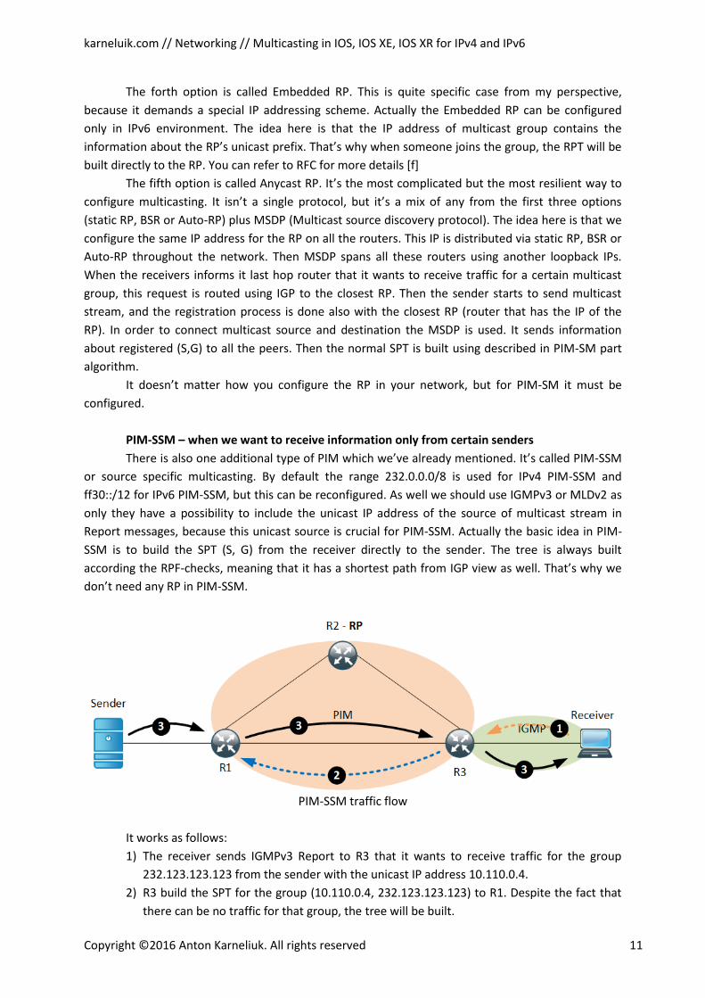
PIM-SSM traffic flow
It works as follows:
1) The receiver sends IGMPv3 Report to R3 that it wants to receive traffic for the group
232.123.123.123 from the sender with the unicast IP address 10.110.0.4.
2) R3 build the SPT for the group (10.110.0.4, 232.123.123.123) to R1. Despite the fact that
there can be no traffic for that group, the tree will be built.
karneluik.com // Networking // Multicasting in IOS, IOS XE, IOS XR for IPv4 and IPv6
Copyright ©2016 Anton Karneliuk. All rights reserved 12
3) When the sender starts to multicast data stream for the group 232.123.123.123, the data
will be forwarder along the built SPT to R3 and then to receiver.
Okay… We have explained a main theory that we need know when we speak about
multicasting. But it isn’t all, of course. Many things were just mentioned or explained in brief words
just to provide you the understanding about its operation. Something we haven’t said, because we
don’t want you to run away in a fear due to overwhelming amount of theory and details. From my
understanding the best book that you should read about multicast is Routing TCP/IP volume 2, if you
want to dig into the details like timers and message format deeper[g]. Though it’s quite old, it has
very good examples and traces. Now we jump into configuration phase. And here some surprises for
you will be, especially at Cisco IOS XR. Despite the big volume of the theory the configuration of
multicasting and multicast routing on all Cisco devices is quite quick and easy in general.
Configuration of multicast routing
If i describe all the possible configuration of multicast, it’ll take tons of pages. I don’t want it,
because you’ll be bored. I will just provide the configuration and explanation of the most important
and/or recent multicast technologies. Due to this aim I will describe the configuration of PIM-SM,
PIM-SSM and PIM-bidir both for IPv4 and IPv6 at Cisco IOS, IOS XE and IOS XR platform. The MSDP is
also very important, but I won’t describe it in this article. It will be described in the separate one, if I
write it :-) The most basic configuration of multicast routing on IOS takes 2 commands at all the
routers in the network and 4 commands at the router which performs the function of RP. Let’s
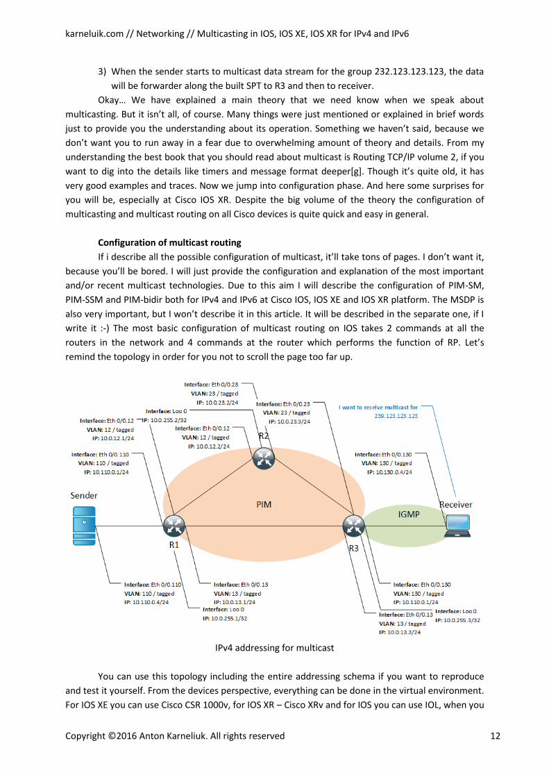
remind the topology in order for you not to scroll the page too far up.
IPv4 addressing for multicast
You can use this topology including the entire addressing schema if you want to reproduce
and test it yourself. From the devices perspective, everything can be done in the virtual environment.
For IOS XE you can use Cisco CSR 1000v, for IOS XR – Cisco XRv and for IOS you can use IOL, when you
karneluik.com // Networking // Multicasting in IOS, IOS XE, IOS XR for IPv4 and IPv6
Copyright ©2016 Anton Karneliuk. All rights reserved 13
find the necessary image. The first two products can be downloaded from the official Cisco website.
Actually you need 4 instances of the equipment, as we’ll configure the sender and the receiver on the
same router just in different VRFs. Such configuration we do due to minimization of using resources.
All the configuration is done using the laptop with Core i7-4810MQ CPU @ 2,80 GHz and 8GB RAM. If
you have enough capacity, you can configure everything as separate routers. In terms of RAM usage
we have the following parameters:
1) Each Cisco XRv demands at least 2 GB per instance, but actually uses lower depending on
configured features/timers. At the official Cisco website it’s stated that you have to have
at least 3 GB [h]
2) Each Cisco CSR 1000v demands at least 2,5 GB per instance and it usually uses all the
provided memory. At the Cisco website it’s stated that you need have at least 2,5 Gb RAM
for IOS XE 3.12 and 4 Gb for IOS XE 3.14 [i, j]
3) For IOL images the demands are usually low, and as I heard and you can run up to 20
routing instance at just one VM with 5 Gb of RAM. Though you can experience some
delays in routers’ response.
As you can see, the necessary RAM is lower in reality than in the official documentation. I’ve
written this article with the numbers that I provide. But it can occur that some other feature won’t
work due to insufficient amount of memory. If you face some problems with your virtual lab, first of
all you should allocate more RAM and then check. May be it’ll help you. If not, then you should look
for a solution in the Internet.
Case #1 – configuration of PIM-SM for IPv4 at Cisco IOS / IOS XE
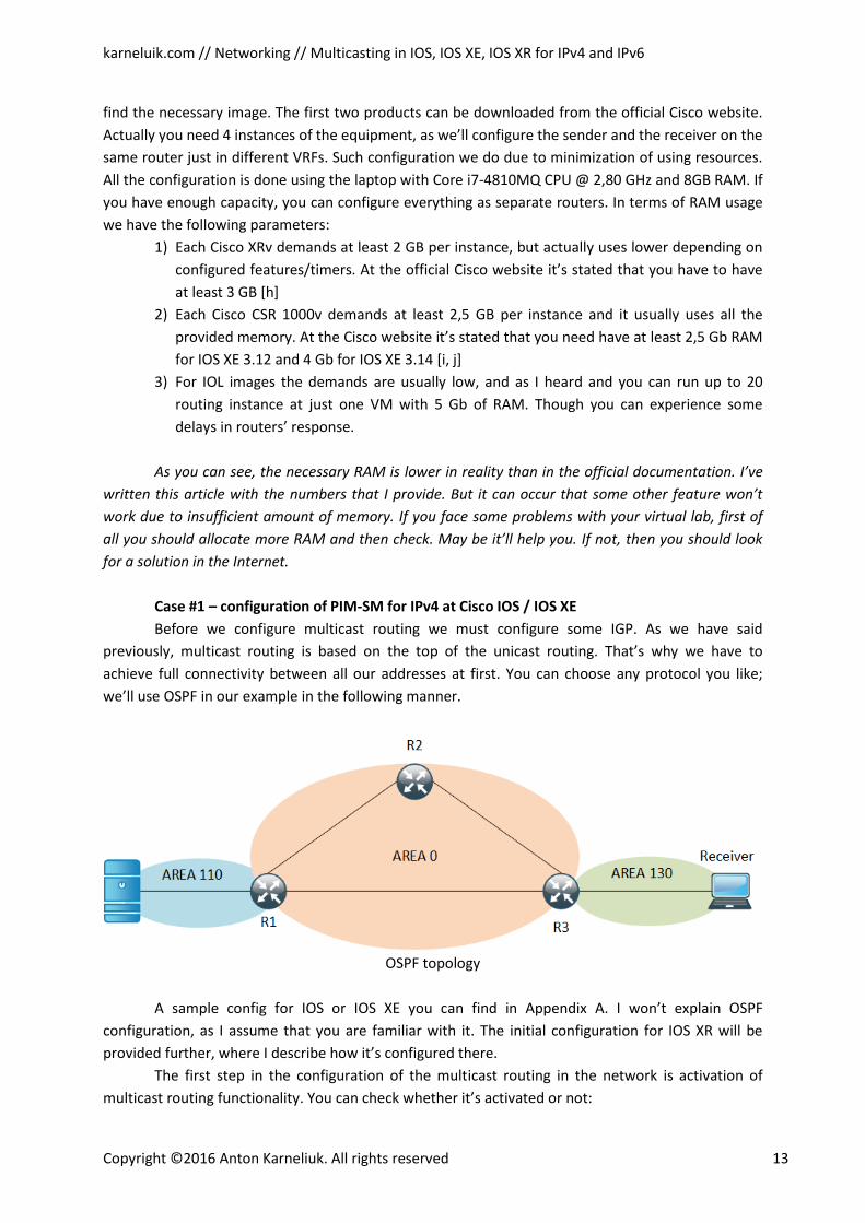
Before we configure multicast routing we must configure some IGP. As we have said
previously, multicast routing is based on the top of the unicast routing. That’s why we have to
achieve full connectivity between all our addresses at first. You can choose any protocol you like;
we’ll use OSPF in our example in the following manner.
OSPF topology
A sample config for IOS or IOS XE you can find in Appendix A. I won’t explain OSPF
configuration, as I assume that you are familiar with it. The initial configuration for IOS XR will be
provided further, where I describe how it’s configured there.
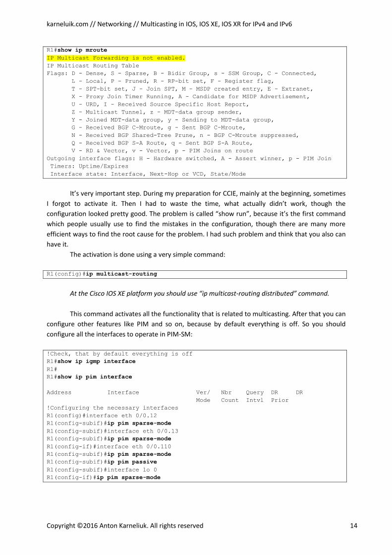
The first step in the configuration of the multicast routing in the network is activation of
multicast routing functionality. You can check whether it’s activated or not:
karneluik.com // Networking // Multicasting in IOS, IOS XE, IOS XR for IPv4 and IPv6
Copyright ©2016 Anton Karneliuk. All rights reserved 14
R1#show ip mroute IP Multicast Forwarding is not enabled. IP Multicast Routing Table
Flags: D - Dense, S - Sparse, B - Bidir Group, s - SSM Group, C - Connected,
L - Local, P - Pruned, R - RP-bit set, F - Register flag,
T - SPT-bit set, J - Join SPT, M - MSDP created entry, E - Extranet,
X - Proxy Join Timer Running, A - Candidate for MSDP Advertisement,
U - URD, I - Received Source Specific Host Report,
Z - Multicast Tunnel, z - MDT-data group sender,
Y - Joined MDT-data group, y - Sending to MDT-data group,
G - Received BGP C-Mroute, g - Sent BGP C-Mroute,
N - Received BGP Shared-Tree Prune, n - BGP C-Mroute suppressed,
Q - Received BGP S-A Route, q - Sent BGP S-A Route,
V - RD & Vector, v - Vector, p - PIM Joins on route
Outgoing interface flags: H - Hardware switched, A - Assert winner, p - PIM Join
Timers: Uptime/Expires
Interface state: Interface, Next-Hop or VCD, State/Mode
It’s very important step. During my preparation for CCIE, mainly at the beginning, sometimes
I forgot to activate it. Then I had to waste the time, what actually didn’t work, though the
configuration looked pretty good. The problem is called “show run”, because it’s the first command
which people usually use to find the mistakes in the configuration, though there are many more
efficient ways to find the root cause for the problem. I had such problem and think that you also can
have it.
The activation is done using a very simple command:
R1(config)#ip multicast-routing
At the Cisco IOS XE platform you should use “ip multicast-routing distributed” command.
This command activates all the functionality that is related to multicasting. After that you can
configure other features like PIM and so on, because by default everything is off. So you should
configure all the interfaces to operate in PIM-SM:
!Check, that by default everything is off
R1#show ip igmp interface R1#
R1#show ip pim interface
Address Interface Ver/ Nbr Query DR DR
Mode Count Intvl Prior
!Configuring the necessary interfaces
R1(config)#interface eth 0/0.12
R1(config-subif)#ip pim sparse-mode R1(config-subif)#interface eth 0/0.13
R1(config-subif)#ip pim sparse-mode R1(config-if)#interface eth 0/0.110
R1(config-subif)#ip pim sparse-mode R1(config-subif)#ip pim passive R1(config-subif)#interface lo 0
R1(config-if)#ip pim sparse-mode
karneluik.com // Networking // Multicasting in IOS, IOS XE, IOS XR for IPv4 and IPv6
Copyright ©2016 Anton Karneliuk. All rights reserved 15
At the interface level you choose into which mode the PIM should operate. There are some
other options, but this is the best one. During the configuration of the router you will see the
following messages:
000042: *Oct 21 09:07:02.875: %PIM-5-DRCHG: DR change from neighbor 0.0.0.0 to
10.0.12.1 on interface Ethernet0/0.12
At the first configured device the designated router (DR) will be always set to itself. For the
others, there will be the election of the DR. The DR is the router who is responsible for registering the
sender/receivers with the RP. Here are some remarks about the configuration:
1) PIM must be configured on the interface facing to the receivers and senders. It might be
not secure to send PIM messages to the hosts, so you can configure this port as passive
for PIM. Think about it like passive interface in OSPF or EIGRP. But you also must
remember that this feature works only if you have just one router facing the clients. If
there are two routers for redundancy, you mustn’t configure this feature as the routers
should speak to each other at the LAN segment as well. Configuring this feature in the
redundancy scenario will break PIM operation.
2) PIM must be configured at the loopback interface at the Rendezvous Point (RP). In other
cases it isn’t necessary, though it doesn’t break anything. So you can configure it
everywhere.
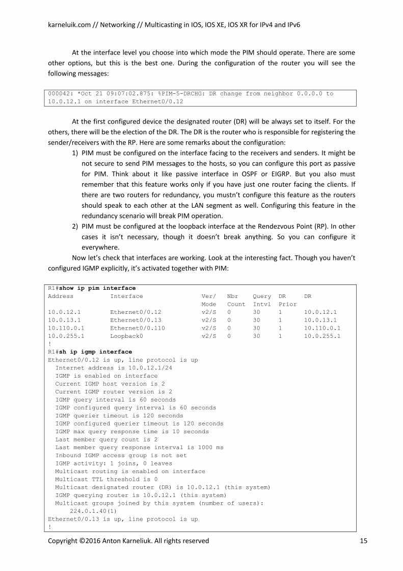
Now let’s check that interfaces are working. Look at the interesting fact. Though you haven’t
configured IGMP explicitly, it’s activated together with PIM:
R1#show ip pim interface
Address Interface Ver/ Nbr Query DR DR
Mode Count Intvl Prior
10.0.12.1 Ethernet0/0.12 v2/S 0 30 1 10.0.12.1
10.0.13.1 Ethernet0/0.13 v2/S 0 30 1 10.0.13.1
10.110.0.1 Ethernet0/0.110 v2/S 0 30 1 10.110.0.1
10.0.255.1 Loopback0 v2/S 0 30 1 10.0.255.1
!
R1#sh ip igmp interface
Ethernet0/0.12 is up, line protocol is up
Internet address is 10.0.12.1/24
IGMP is enabled on interface
Current IGMP host version is 2
Current IGMP router version is 2
IGMP query interval is 60 seconds
IGMP configured query interval is 60 seconds
IGMP querier timeout is 120 seconds
IGMP configured querier timeout is 120 seconds
IGMP max query response time is 10 seconds
Last member query count is 2
Last member query response interval is 1000 ms
Inbound IGMP access group is not set
IGMP activity: 1 joins, 0 leaves
Multicast routing is enabled on interface
Multicast TTL threshold is 0
Multicast designated router (DR) is 10.0.12.1 (this system)
IGMP querying router is 10.0.12.1 (this system)
Multicast groups joined by this system (number of users):
224.0.1.40(1)
Ethernet0/0.13 is up, line protocol is up
!
karneluik.com // Networking // Multicasting in IOS, IOS XE, IOS XR for IPv4 and IPv6
Copyright ©2016 Anton Karneliuk. All rights reserved 16
Output is omitted
!
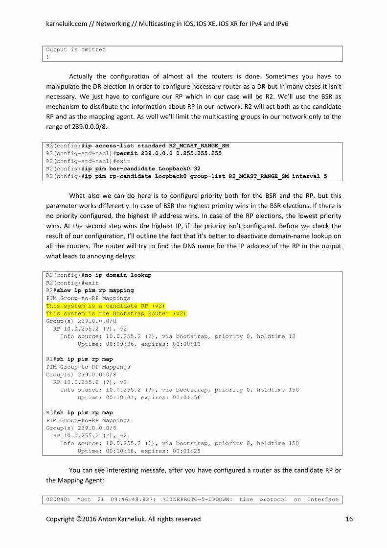
Actually the configuration of almost all the routers is done. Sometimes you have to
manipulate the DR election in order to configure necessary router as a DR but in many cases it isn’t
necessary. We just have to configure our RP which in our case will be R2. We’ll use the BSR as
mechanism to distribute the information about RP in our network. R2 will act both as the candidate
RP and as the mapping agent. As well we’ll limit the multicasting groups in our network only to the
range of 239.0.0.0/8.
R2(config)#ip access-list standard R2_MCAST_RANGE_SM R2(config-std-nacl)#permit 239.0.0.0 0.255.255.255 R2(config-std-nacl)#exit
R2(config)#ip pim bsr-candidate Loopback0 32 R2(config)#ip pim rp-candidate Loopback0 group-list R2_MCAST_RANGE_SM interval 5
What also we can do here is to configure priority both for the BSR and the RP, but this
parameter works differently. In case of BSR the highest priority wins in the BSR elections. If there is
no priority configured, the highest IP address wins. In case of the RP elections, the lowest priority
wins. At the second step wins the highest IP, if the priority isn’t configured. Before we check the
result of our configuration, I’ll outline the fact that it’s better to deactivate domain-name lookup on
all the routers. The router will try to find the DNS name for the IP address of the RP in the output
what leads to annoying delays:
R2(config)#no ip domain lookup R2(config)#exit
R2#show ip pim rp mapping PIM Group-to-RP Mappings
This system is a candidate RP (v2)
This system is the Bootstrap Router (v2) Group(s) 239.0.0.0/8
RP 10.0.255.2 (?), v2
Info source: 10.0.255.2 (?), via bootstrap, priority 0, holdtime 12
Uptime: 00:09:36, expires: 00:00:10
R1#sh ip pim rp map PIM Group-to-RP Mappings
Group(s) 239.0.0.0/8
RP 10.0.255.2 (?), v2
Info source: 10.0.255.2 (?), via bootstrap, priority 0, holdtime 150
Uptime: 00:10:31, expires: 00:01:56
R3#sh ip pim rp map PIM Group-to-RP Mappings
Group(s) 239.0.0.0/8
RP 10.0.255.2 (?), v2
Info source: 10.0.255.2 (?), via bootstrap, priority 0, holdtime 150
Uptime: 00:10:58, expires: 00:01:29
You can see interesting messafe, after you have configured a router as the candidate RP or
the Mapping Agent:
000040: *Oct 21 09:46:48.827: %LINEPROTO-5-UPDOWN: Line protocol on Interface
karneluik.com // Networking // Multicasting in IOS, IOS XE, IOS XR for IPv4 and IPv6
Copyright ©2016 Anton Karneliuk. All rights reserved 17
Tunnel0, changed state to up
000041: *Oct 21 09:46:48.828: %LINEPROTO-5-UPDOWN: Line protocol on Interface
Tunnel1, changed state to up
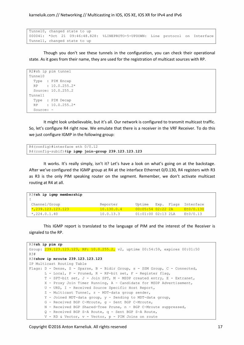
Though you don’t see these tunnels in the configuration, you can check their operational
state. As it goes from their name, they are used for the registration of multicast sources with RP.
R2#sh ip pim tunnel
Tunnel0
Type : PIM Encap
RP : 10.0.255.2*
Source: 10.0.255.2
Tunnel1
Type : PIM Decap
RP : 10.0.255.2*
Source: -
It might look unbelievable, but it’s all. Our network is configured to transmit multicast traffic.
So, let’s configure R4 right now. We emulate that there is a receiver in the VRF Receiver. To do this
we just configure IGMP in the following group:
R4(config)#interface eth 0/0.12
R4(config-subif)#ip igmp join-group 239.123.123.123
It works. It’s really simply, isn’t it? Let’s have a look on what’s going on at the backstage.
After we’ve configured the IGMP group at R4 at the interface Ethernet 0/0.130, R4 registers with R3
as R3 is the only PIM speaking router on the segment. Remember, we don’t activate multicast
routing at R4 at all.
R3#sh ip igmp membership !
Channel/Group Reporter Uptime Exp. Flags Interface
*,239.123.123.123 10.130.0.4 00:05:54 02:22 2A Et0/0.130 *,224.0.1.40 10.0.13.3 01:01:00 02:13 2LA Et0/0.13
This IGMP report is translated to the language of PIM and the interest of the Receiver is
signaled to the RP.
R3#sh ip pim rp Group: 239.123.123.123, RP: 10.0.255.2, v2, uptime 00:54:59, expires 00:01:50 R3#
R3#show ip mroute 239.123.123.123 IP Multicast Routing Table
Flags: D - Dense, S - Sparse, B - Bidir Group, s - SSM Group, C - Connected,
L - Local, P - Pruned, R - RP-bit set, F - Register flag,
T - SPT-bit set, J - Join SPT, M - MSDP created entry, E - Extranet,
X - Proxy Join Timer Running, A - Candidate for MSDP Advertisement,
U - URD, I - Received Source Specific Host Report,
Z - Multicast Tunnel, z - MDT-data group sender,
Y - Joined MDT-data group, y - Sending to MDT-data group,
G - Received BGP C-Mroute, g - Sent BGP C-Mroute,
N - Received BGP Shared-Tree Prune, n - BGP C-Mroute suppressed,
Q - Received BGP S-A Route, q - Sent BGP S-A Route,
V - RD & Vector, v - Vector, p - PIM Joins on route
karneluik.com // Networking // Multicasting in IOS, IOS XE, IOS XR for IPv4 and IPv6
Copyright ©2016 Anton Karneliuk. All rights reserved 18
Outgoing interface flags: H - Hardware switched, A - Assert winner, p - PIM Join
Timers: Uptime/Expires
Interface state: Interface, Next-Hop or VCD, State/Mode
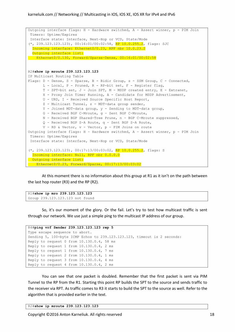
(*, 239.123.123.123), 00:16:01/00:02:58, RP 10.0.255.2, flags: SJC Incoming interface: Ethernet0/0.23, RPF nbr 10.0.23.2 Outgoing interface list: Ethernet0/0.130, Forward/Sparse-Dense, 00:16:01/00:02:58
R2#show ip mroute 239.123.123.123 IP Multicast Routing Table
Flags: D - Dense, S - Sparse, B - Bidir Group, s - SSM Group, C - Connected,
L - Local, P - Pruned, R - RP-bit set, F - Register flag,
T - SPT-bit set, J - Join SPT, M - MSDP created entry, E - Extranet,
X - Proxy Join Timer Running, A - Candidate for MSDP Advertisement,
U - URD, I - Received Source Specific Host Report,
Z - Multicast Tunnel, z - MDT-data group sender,
Y - Joined MDT-data group, y - Sending to MDT-data group,
G - Received BGP C-Mroute, g - Sent BGP C-Mroute,
N - Received BGP Shared-Tree Prune, n - BGP C-Mroute suppressed,
Q - Received BGP S-A Route, q - Sent BGP S-A Route,
V - RD & Vector, v - Vector, p - PIM Joins on route
Outgoing interface flags: H - Hardware switched, A - Assert winner, p - PIM Join
Timers: Uptime/Expires
Interface state: Interface, Next-Hop or VCD, State/Mode
(*, 239.123.123.123), 00:17:13/00:03:02, RP 10.0.255.2, flags: S Incoming interface: Null, RPF nbr 0.0.0.0 Outgoing interface list:
Ethernet0/0.23, Forward/Sparse, 00:17:13/00:03:02
At this moment there is no information about this group at R1 as it isn’t on the path between
the last hop router (R3) and the RP (R2).
R1#show ip mro 239.123.123.123 Group 239.123.123.123 not found
So, it’s our moment of the glory. Or the fail. Let’s try to test how multicast traffic is sent
through our network. We use just a simple ping to the multicast IP address of our group.
R4#ping vrf Sender 239.123.123.123 rep 5 Type escape sequence to abort.
Sending 5, 100-byte ICMP Echos to 239.123.123.123, timeout is 2 seconds:
Reply to request 0 from 10.130.0.4, 58 ms
Reply to request 1 from 10.130.0.4, 2 ms
Reply to request 1 from 10.130.0.4, 7 ms
Reply to request 2 from 10.130.0.4, 1 ms
Reply to request 3 from 10.130.0.4, 4 ms
Reply to request 4 from 10.130.0.4, 2 ms
You can see that one packet is doubled. Remember that the first packet is sent via PIM
Tunnel to the RP from the R1. Starting this point RP builds the SPT to the source and sends traffic to
the receiver via RPT. As traffic comes to R3 it starts to build the SPT to the source as well. Refer to the
algorithm that is provided earlier in the text.
R2#show ip mroute 239.123.123.123
karneluik.com // Networking // Multicasting in IOS, IOS XE, IOS XR for IPv4 and IPv6
Copyright ©2016 Anton Karneliuk. All rights reserved 19
IP Multicast Routing Table
Flags: D - Dense, S - Sparse, B - Bidir Group, s - SSM Group, C - Connected,
L - Local, P - Pruned, R - RP-bit set, F - Register flag,
T - SPT-bit set, J - Join SPT, M - MSDP created entry, E - Extranet,
X - Proxy Join Timer Running, A - Candidate for MSDP Advertisement,
U - URD, I - Received Source Specific Host Report,
Z - Multicast Tunnel, z - MDT-data group sender,
Y - Joined MDT-data group, y - Sending to MDT-data group,
G - Received BGP C-Mroute, g - Sent BGP C-Mroute,
N - Received BGP Shared-Tree Prune, n - BGP C-Mroute suppressed,
Q - Received BGP S-A Route, q - Sent BGP S-A Route,
V - RD & Vector, v - Vector, p - PIM Joins on route
Outgoing interface flags: H - Hardware switched, A - Assert winner, p - PIM Join
Timers: Uptime/Expires
Interface state: Interface, Next-Hop or VCD, State/Mode
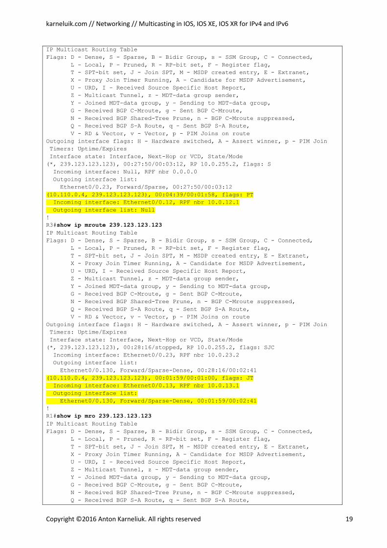
(*, 239.123.123.123), 00:27:50/00:03:12, RP 10.0.255.2, flags: S
Incoming interface: Null, RPF nbr 0.0.0.0
Outgoing interface list:
Ethernet0/0.23, Forward/Sparse, 00:27:50/00:03:12
(10.110.0.4, 239.123.123.123), 00:04:39/00:01:58, flags: PT
Incoming interface: Ethernet0/0.12, RPF nbr 10.0.12.1
Outgoing interface list: Null !
R3#show ip mroute 239.123.123.123 IP Multicast Routing Table
Flags: D - Dense, S - Sparse, B - Bidir Group, s - SSM Group, C - Connected,
L - Local, P - Pruned, R - RP-bit set, F - Register flag,
T - SPT-bit set, J - Join SPT, M - MSDP created entry, E - Extranet,
X - Proxy Join Timer Running, A - Candidate for MSDP Advertisement,
U - URD, I - Received Source Specific Host Report,
Z - Multicast Tunnel, z - MDT-data group sender,
Y - Joined MDT-data group, y - Sending to MDT-data group,
G - Received BGP C-Mroute, g - Sent BGP C-Mroute,
N - Received BGP Shared-Tree Prune, n - BGP C-Mroute suppressed,
Q - Received BGP S-A Route, q - Sent BGP S-A Route,
V - RD & Vector, v - Vector, p - PIM Joins on route
Outgoing interface flags: H - Hardware switched, A - Assert winner, p - PIM Join
Timers: Uptime/Expires
Interface state: Interface, Next-Hop or VCD, State/Mode
(*, 239.123.123.123), 00:28:16/stopped, RP 10.0.255.2, flags: SJC
Incoming interface: Ethernet0/0.23, RPF nbr 10.0.23.2
Outgoing interface list:
Ethernet0/0.130, Forward/Sparse-Dense, 00:28:16/00:02:41
(10.110.0.4, 239.123.123.123), 00:01:59/00:01:00, flags: JT
Incoming interface: Ethernet0/0.13, RPF nbr 10.0.13.1
Outgoing interface list:
Ethernet0/0.130, Forward/Sparse-Dense, 00:01:59/00:02:41 !
R1#show ip mro 239.123.123.123 IP Multicast Routing Table
Flags: D - Dense, S - Sparse, B - Bidir Group, s - SSM Group, C - Connected,
L - Local, P - Pruned, R - RP-bit set, F - Register flag,
T - SPT-bit set, J - Join SPT, M - MSDP created entry, E - Extranet,
X - Proxy Join Timer Running, A - Candidate for MSDP Advertisement,
U - URD, I - Received Source Specific Host Report,
Z - Multicast Tunnel, z - MDT-data group sender,
Y - Joined MDT-data group, y - Sending to MDT-data group,
G - Received BGP C-Mroute, g - Sent BGP C-Mroute,
N - Received BGP Shared-Tree Prune, n - BGP C-Mroute suppressed,
Q - Received BGP S-A Route, q - Sent BGP S-A Route,
karneluik.com // Networking // Multicasting in IOS, IOS XE, IOS XR for IPv4 and IPv6
Copyright ©2016 Anton Karneliuk. All rights reserved 20
V - RD & Vector, v - Vector, p - PIM Joins on route
Outgoing interface flags: H - Hardware switched, A - Assert winner, p - PIM Join
Timers: Uptime/Expires
Interface state: Interface, Next-Hop or VCD, State/Mode
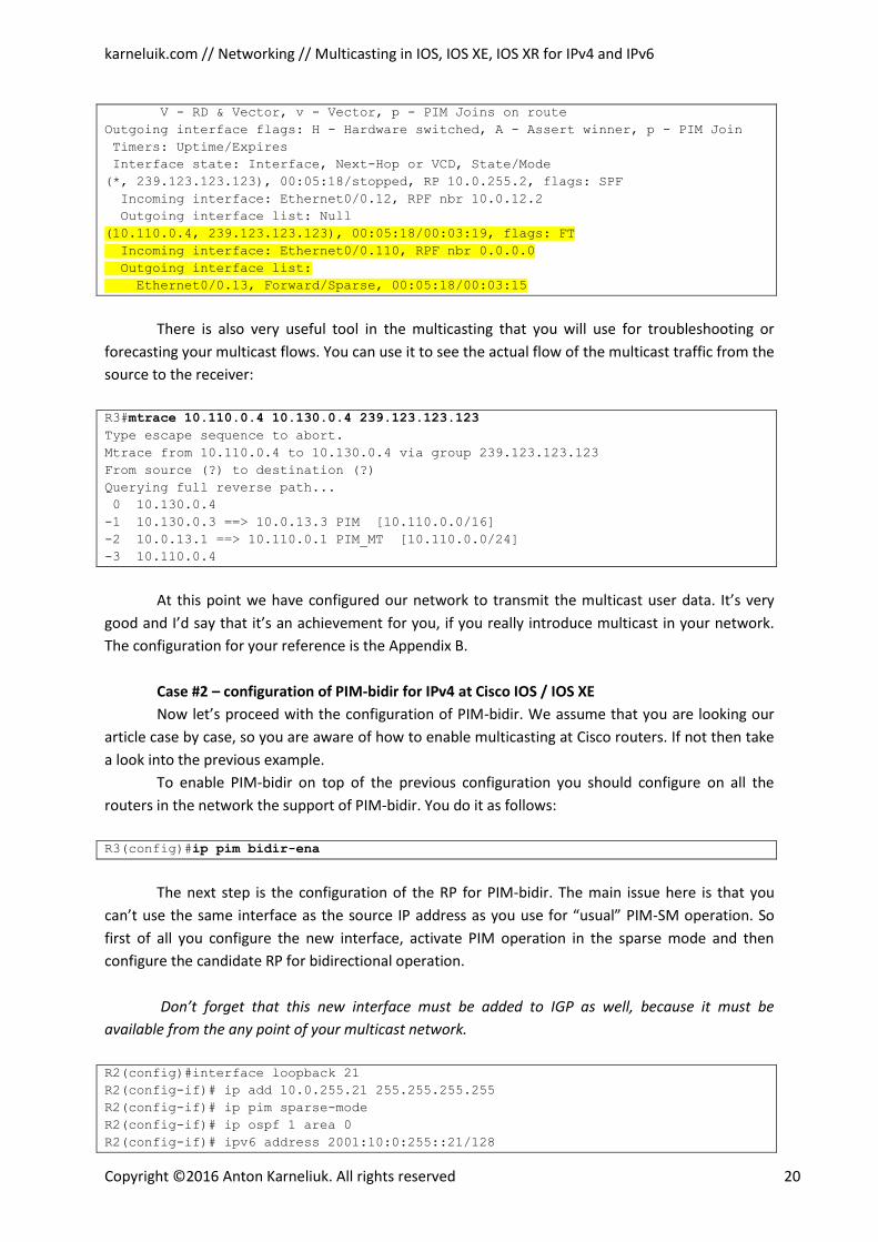
(*, 239.123.123.123), 00:05:18/stopped, RP 10.0.255.2, flags: SPF
Incoming interface: Ethernet0/0.12, RPF nbr 10.0.12.2
Outgoing interface list: Null
(10.110.0.4, 239.123.123.123), 00:05:18/00:03:19, flags: FT
Incoming interface: Ethernet0/0.110, RPF nbr 0.0.0.0
Outgoing interface list:
Ethernet0/0.13, Forward/Sparse, 00:05:18/00:03:15
There is also very useful tool in the multicasting that you will use for troubleshooting or
forecasting your multicast flows. You can use it to see the actual flow of the multicast traffic from the
source to the receiver:
R3#mtrace 10.110.0.4 10.130.0.4 239.123.123.123 Type escape sequence to abort.
Mtrace from 10.110.0.4 to 10.130.0.4 via group 239.123.123.123
From source (?) to destination (?)
Querying full reverse path...
0 10.130.0.4
-1 10.130.0.3 ==> 10.0.13.3 PIM [10.110.0.0/16]
-2 10.0.13.1 ==> 10.110.0.1 PIM_MT [10.110.0.0/24]
-3 10.110.0.4
At this point we have configured our network to transmit the multicast user data. It’s very
good and I’d say that it’s an achievement for you, if you really introduce multicast in your network.
The configuration for your reference is the Appendix B.
Case #2 – configuration of PIM-bidir for IPv4 at Cisco IOS / IOS XE
Now let’s proceed with the configuration of PIM-bidir. We assume that you are looking our
article case by case, so you are aware of how to enable multicasting at Cisco routers. If not then take
a look into the previous example.
To enable PIM-bidir on top of the previous configuration you should configure on all the
routers in the network the support of PIM-bidir. You do it as follows:
R3(config)#ip pim bidir-ena
The next step is the configuration of the RP for PIM-bidir. The main issue here is that you
can’t use the same interface as the source IP address as you use for “usual” PIM-SM operation. So
first of all you configure the new interface, activate PIM operation in the sparse mode and then
configure the candidate RP for bidirectional operation.
Don’t forget that this new interface must be added to IGP as well, because it must be
available from the any point of your multicast network.
R2(config)#interface loopback 21
R2(config-if)# ip add 10.0.255.21 255.255.255.255
R2(config-if)# ip pim sparse-mode
R2(config-if)# ip ospf 1 area 0
R2(config-if)# ipv6 address 2001:10:0:255::21/128
karneluik.com // Networking // Multicasting in IOS, IOS XE, IOS XR for IPv4 and IPv6
Copyright ©2016 Anton Karneliuk. All rights reserved 21
R2(config-if)# ospfv3 1 ipv6 area 0
R2(config-if)#!
R2(config-if)#ip access-list stan R2_MCAST_RANGE_BIDIR
R2(config-std-nacl)# permit 238.0.0.0 0.255.255.255
R2(config-std-nacl)#!
R2(config-std-nacl)#ip pim rp-candidate loo21 group R2_MCAST_RANGE_BIDIR int 5
bidir
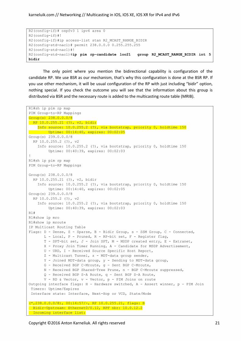
The only point where you mention the bidirectional capability is configuration of the
candidate RP. We use BSR as our mechanism, that’s why this configuration is done at the BSR RP. If
you use other mechanism, it will be usual configuration of the RP with just including “bidir” option,
nothing special. If you check the outcome you will see that the information about this group is
distributed via BSR and the necessary route is added to the multicasting route table (MRIB).
R1#sh ip pim rp map
PIM Group-to-RP Mappings
Group(s) 238.0.0.0/8
RP 10.0.255.21 (?), v2, bidir Info source: 10.0.255.2 (?), via bootstrap, priority 0, holdtime 150 Uptime: 00:14:40, expires: 00:02:05 Group(s) 239.0.0.0/8
RP 10.0.255.2 (?), v2
Info source: 10.0.255.2 (?), via bootstrap, priority 0, holdtime 150
Uptime: 00:40:39, expires: 00:02:03
!
R1#sh ip pim rp map
PIM Group-to-RP Mappings
Group(s) 238.0.0.0/8
RP 10.0.255.21 (?), v2, bidir
Info source: 10.0.255.2 (?), via bootstrap, priority 0, holdtime 150
Uptime: 00:14:40, expires: 00:02:05
Group(s) 239.0.0.0/8
RP 10.0.255.2 (?), v2
Info source: 10.0.255.2 (?), via bootstrap, priority 0, holdtime 150
Uptime: 00:40:39, expires: 00:02:03
R1#
R1#show ip mro
R1#show ip mroute
IP Multicast Routing Table
Flags: D - Dense, S - Sparse, B - Bidir Group, s - SSM Group, C - Connected,
L - Local, P - Pruned, R - RP-bit set, F - Register flag,
T - SPT-bit set, J - Join SPT, M - MSDP created entry, E - Extranet,
X - Proxy Join Timer Running, A - Candidate for MSDP Advertisement,
U - URD, I - Received Source Specific Host Report,
Z - Multicast Tunnel, z - MDT-data group sender,
Y - Joined MDT-data group, y - Sending to MDT-data group,
G - Received BGP C-Mroute, g - Sent BGP C-Mroute,
N - Received BGP Shared-Tree Prune, n - BGP C-Mroute suppressed,
Q - Received BGP S-A Route, q - Sent BGP S-A Route,
V - RD & Vector, v - Vector, p - PIM Joins on route
Outgoing interface flags: H - Hardware switched, A - Assert winner, p - PIM Join
Timers: Uptime/Expires
Interface state: Interface, Next-Hop or VCD, State/Mode
(*,238.0.0.0/8), 00:14:57/-, RP 10.0.255.21, flags: B
Bidir-Upstream: Ethernet0/0.12, RPF nbr: 10.0.12.2
Incoming interface list:
karneluik.com // Networking // Multicasting in IOS, IOS XE, IOS XR for IPv4 and IPv6
Copyright ©2016 Anton Karneliuk. All rights reserved 22
Loopback0, Accepting/Sparse
Ethernet0/0.110, Accepting/Sparse-Dense
Ethernet0/0.12, Accepting/Sparse
(*, 224.0.1.40), 00:41:58/00:02:05, RP 0.0.0.0, flags: DCL
Incoming interface: Null, RPF nbr 0.0.0.0
Outgoing interface list:
Loopback0, Forward/Sparse, 00:41:57/00:02:05
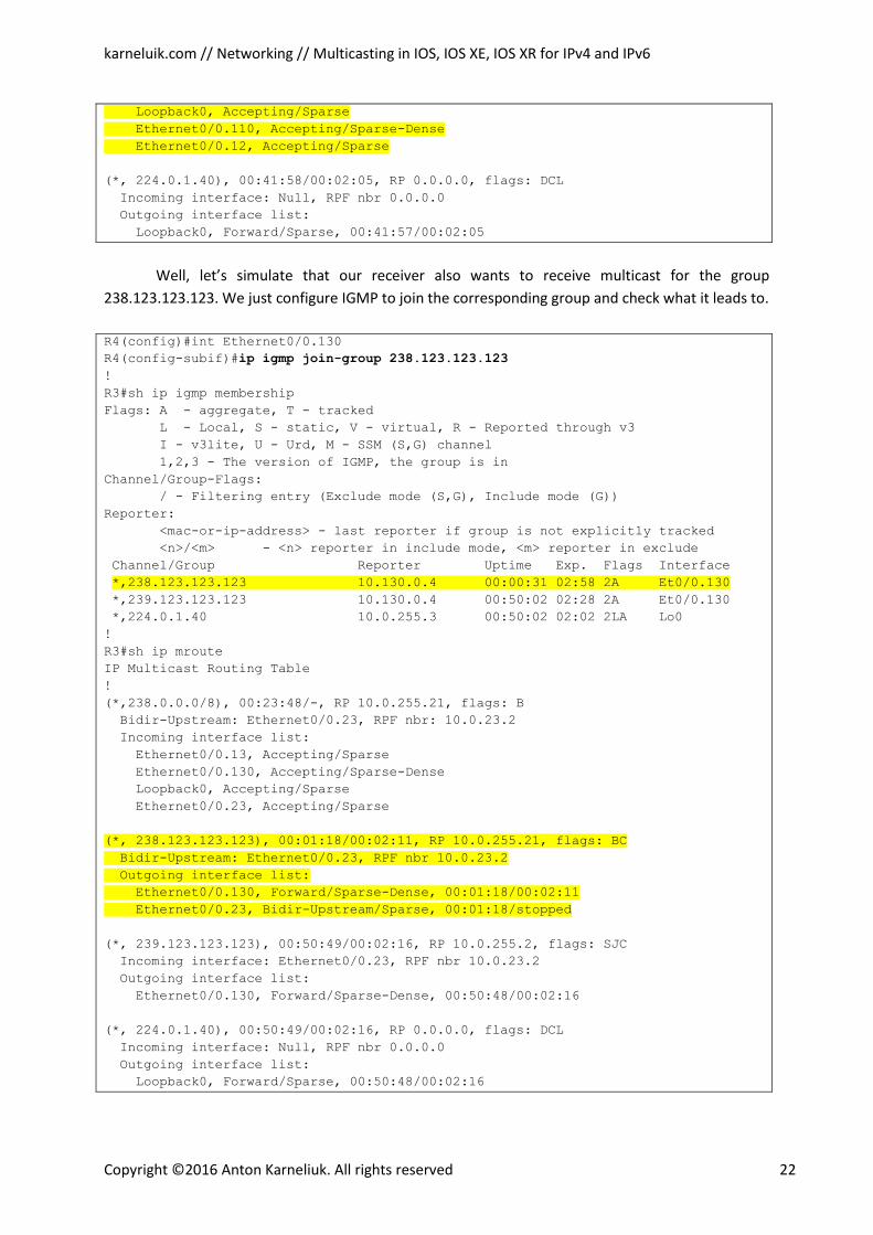
Well, let’s simulate that our receiver also wants to receive multicast for the group
238.123.123.123. We just configure IGMP to join the corresponding group and check what it leads to.
R4(config)#int Ethernet0/0.130
R4(config-subif)#ip igmp join-group 238.123.123.123 !
R3#sh ip igmp membership
Flags: A - aggregate, T - tracked
L - Local, S - static, V - virtual, R - Reported through v3
I - v3lite, U - Urd, M - SSM (S,G) channel
1,2,3 - The version of IGMP, the group is in
Channel/Group-Flags:
/ - Filtering entry (Exclude mode (S,G), Include mode (G))
Reporter:
<mac-or-ip-address> - last reporter if group is not explicitly tracked
<n>/<m> - <n> reporter in include mode, <m> reporter in exclude
Channel/Group Reporter Uptime Exp. Flags Interface
*,238.123.123.123 10.130.0.4 00:00:31 02:58 2A Et0/0.130 *,239.123.123.123 10.130.0.4 00:50:02 02:28 2A Et0/0.130
*,224.0.1.40 10.0.255.3 00:50:02 02:02 2LA Lo0
!
R3#sh ip mroute
IP Multicast Routing Table
!
(*,238.0.0.0/8), 00:23:48/-, RP 10.0.255.21, flags: B
Bidir-Upstream: Ethernet0/0.23, RPF nbr: 10.0.23.2
Incoming interface list:
Ethernet0/0.13, Accepting/Sparse
Ethernet0/0.130, Accepting/Sparse-Dense
Loopback0, Accepting/Sparse
Ethernet0/0.23, Accepting/Sparse
(*, 238.123.123.123), 00:01:18/00:02:11, RP 10.0.255.21, flags: BC
Bidir-Upstream: Ethernet0/0.23, RPF nbr 10.0.23.2
Outgoing interface list:
Ethernet0/0.130, Forward/Sparse-Dense, 00:01:18/00:02:11
Ethernet0/0.23, Bidir-Upstream/Sparse, 00:01:18/stopped
(*, 239.123.123.123), 00:50:49/00:02:16, RP 10.0.255.2, flags: SJC
Incoming interface: Ethernet0/0.23, RPF nbr 10.0.23.2
Outgoing interface list:
Ethernet0/0.130, Forward/Sparse-Dense, 00:50:48/00:02:16
(*, 224.0.1.40), 00:50:49/00:02:16, RP 0.0.0.0, flags: DCL
Incoming interface: Null, RPF nbr 0.0.0.0
Outgoing interface list:
Loopback0, Forward/Sparse, 00:50:48/00:02:16
karneluik.com // Networking // Multicasting in IOS, IOS XE, IOS XR for IPv4 and IPv6
Copyright ©2016 Anton Karneliuk. All rights reserved 23
You see, that you have both 238.0.0.0/8 and 239.123.123.123 groups in the MRIB on R3, and
the same picture you’ll see at the R2. (Refer to the algorithm above for the details). Just send a
multicast ping from Receiver to sender and check how the PIM-bidir works.
R4%Sender#ping 238.123.123.123 rep 5 Type escape sequence to abort.
Sending 5, 100-byte ICMP Echos to 238.123.123.123, timeout is 2 seconds:
Reply to request 0 from 10.130.0.4, 1 ms
Reply to request 1 from 10.130.0.4, 1 ms
Reply to request 2 from 10.130.0.4, 1 ms
Reply to request 3 from 10.130.0.4, 1 ms
Reply to request 4 from 10.130.0.4, 3 ms
R1#sh ip mroute IP Multicast Routing Table
!
(*,238.0.0.0/8), 00:30:18/-, RP 10.0.255.21, flags: B
Bidir-Upstream: Ethernet0/0.12, RPF nbr: 10.0.12.2
Incoming interface list:
Loopback0, Accepting/Sparse
Ethernet0/0.110, Accepting/Sparse-Dense
Ethernet0/0.12, Accepting/Sparse
(*, 224.0.1.40), 00:57:19/00:02:47, RP 0.0.0.0, flags: DCL
Incoming interface: Null, RPF nbr 0.0.0.0
Outgoing interface list:
Loopback0, Forward/Sparse, 00:57:18/00:02:47
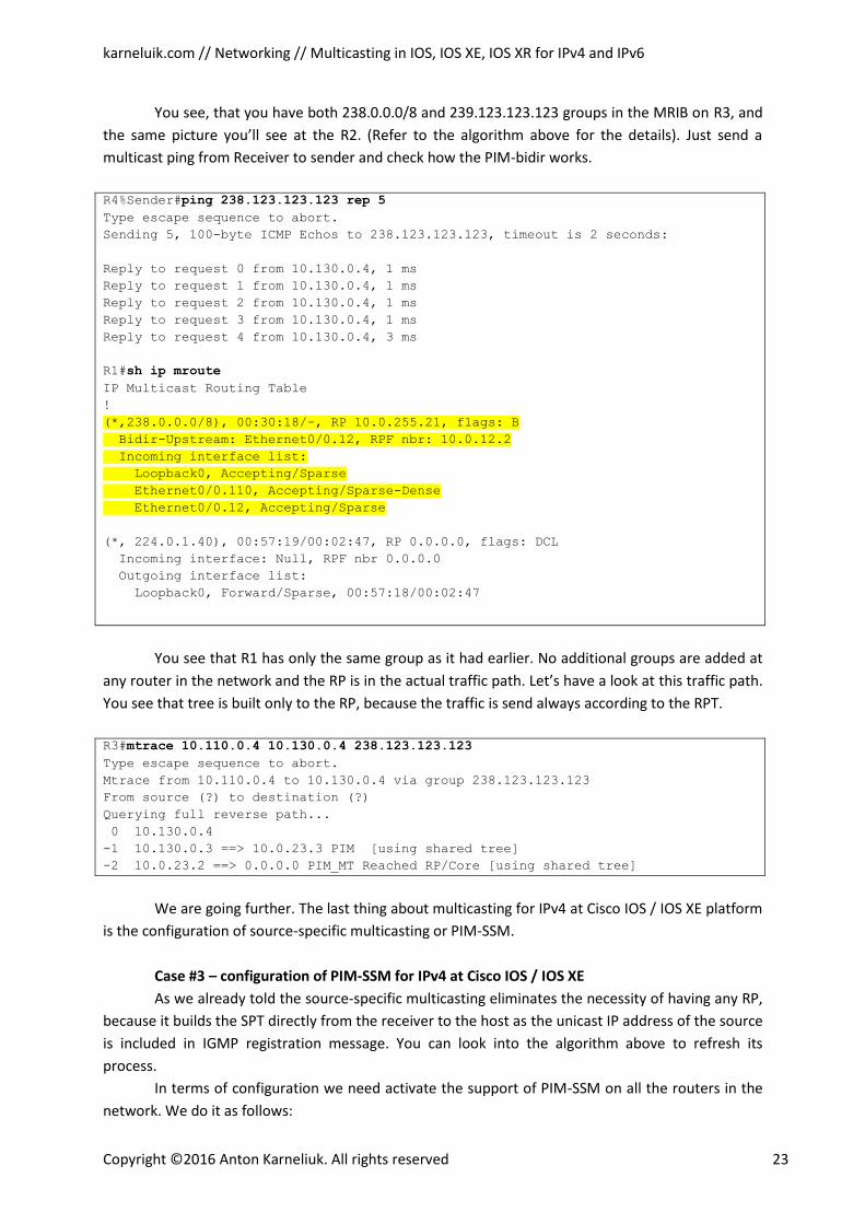
You see that R1 has only the same group as it had earlier. No additional groups are added at
any router in the network and the RP is in the actual traffic path. Let’s have a look at this traffic path.
You see that tree is built only to the RP, because the traffic is send always according to the RPT.
R3#mtrace 10.110.0.4 10.130.0.4 238.123.123.123 Type escape sequence to abort.
Mtrace from 10.110.0.4 to 10.130.0.4 via group 238.123.123.123
From source (?) to destination (?)
Querying full reverse path...
0 10.130.0.4
-1 10.130.0.3 ==> 10.0.23.3 PIM [using shared tree]
-2 10.0.23.2 ==> 0.0.0.0 PIM_MT Reached RP/Core [using shared tree]
We are going further. The last thing about multicasting for IPv4 at Cisco IOS / IOS XE platform
is the configuration of source-specific multicasting or PIM-SSM.
Case #3 – configuration of PIM-SSM for IPv4 at Cisco IOS / IOS XE
As we already told the source-specific multicasting eliminates the necessity of having any RP,
because it builds the SPT directly from the receiver to the host as the unicast IP address of the source
is included in IGMP registration message. You can look into the algorithm above to refresh its
process.
In terms of configuration we need activate the support of PIM-SSM on all the routers in the
network. We do it as follows:
karneluik.com // Networking // Multicasting in IOS, IOS XE, IOS XR for IPv4 and IPv6
Copyright ©2016 Anton Karneliuk. All rights reserved 24
R3(config)#ip pim ssm default
The keyword “default” means that the default range for SSM will be used which is
232.0.0.0/8. If you want to use another group to SSM, you should use keyword “range” and configure
the access-list that allows the necessary multicast IP address range.
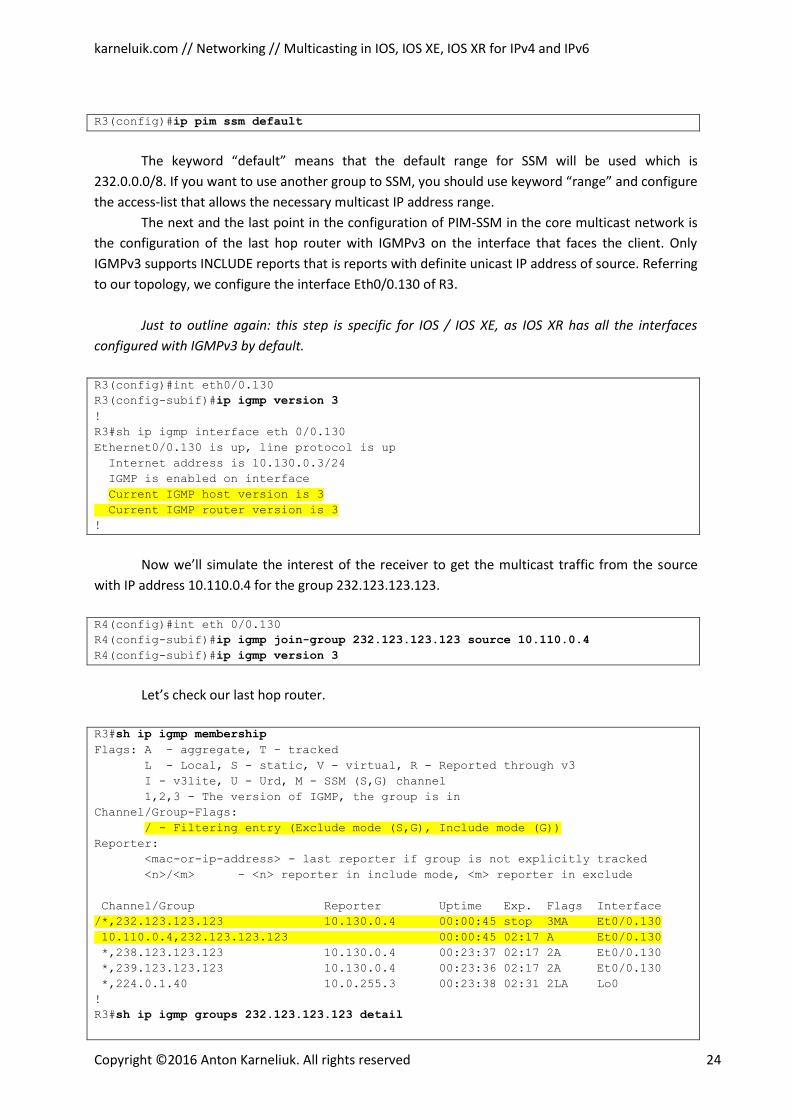
The next and the last point in the configuration of PIM-SSM in the core multicast network is
the configuration of the last hop router with IGMPv3 on the interface that faces the client. Only
IGMPv3 supports INCLUDE reports that is reports with definite unicast IP address of source. Referring
to our topology, we configure the interface Eth0/0.130 of R3.
Just to outline again: this step is specific for IOS / IOS XE, as IOS XR has all the interfaces
configured with IGMPv3 by default.
R3(config)#int eth0/0.130
R3(config-subif)#ip igmp version 3 !
R3#sh ip igmp interface eth 0/0.130
Ethernet0/0.130 is up, line protocol is up
Internet address is 10.130.0.3/24
IGMP is enabled on interface
Current IGMP host version is 3 Current IGMP router version is 3 !
Now we’ll simulate the interest of the receiver to get the multicast traffic from the source
with IP address 10.110.0.4 for the group 232.123.123.123.
R4(config)#int eth 0/0.130
R4(config-subif)#ip igmp join-group 232.123.123.123 source 10.110.0.4 R4(config-subif)#ip igmp version 3
Let’s check our last hop router.
R3#sh ip igmp membership Flags: A - aggregate, T - tracked
L - Local, S - static, V - virtual, R - Reported through v3
I - v3lite, U - Urd, M - SSM (S,G) channel
1,2,3 - The version of IGMP, the group is in
Channel/Group-Flags:
/ - Filtering entry (Exclude mode (S,G), Include mode (G)) Reporter:
<mac-or-ip-address> - last reporter if group is not explicitly tracked
<n>/<m> - <n> reporter in include mode, <m> reporter in exclude
Channel/Group Reporter Uptime Exp. Flags Interface
/*,232.123.123.123 10.130.0.4 00:00:45 stop 3MA Et0/0.130
10.110.0.4,232.123.123.123 00:00:45 02:17 A Et0/0.130 *,238.123.123.123 10.130.0.4 00:23:37 02:17 2A Et0/0.130
*,239.123.123.123 10.130.0.4 00:23:36 02:17 2A Et0/0.130
*,224.0.1.40 10.0.255.3 00:23:38 02:31 2LA Lo0
!
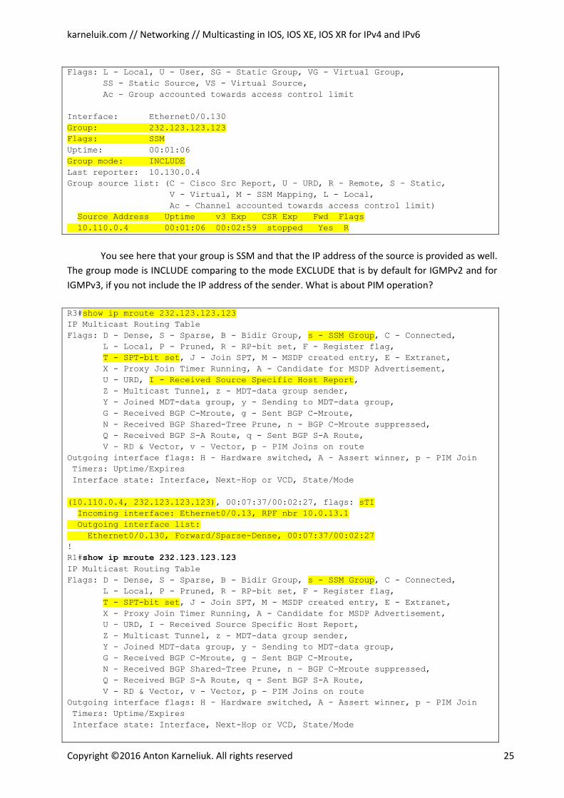
R3#sh ip igmp groups 232.123.123.123 detail
karneluik.com // Networking // Multicasting in IOS, IOS XE, IOS XR for IPv4 and IPv6
Copyright ©2016 Anton Karneliuk. All rights reserved 25
Flags: L - Local, U - User, SG - Static Group, VG - Virtual Group,
SS - Static Source, VS - Virtual Source,
Ac - Group accounted towards access control limit
Interface: Ethernet0/0.130
Group: 232.123.123.123
Flags: SSM Uptime: 00:01:06
Group mode: INCLUDE Last reporter: 10.130.0.4
Group source list: (C - Cisco Src Report, U - URD, R - Remote, S - Static,
V - Virtual, M - SSM Mapping, L - Local,
Ac - Channel accounted towards access control limit)
Source Address Uptime v3 Exp CSR Exp Fwd Flags 10.110.0.4 00:01:06 00:02:59 stopped Yes R
You see here that your group is SSM and that the IP address of the source is provided as well.
The group mode is INCLUDE comparing to the mode EXCLUDE that is by default for IGMPv2 and for
IGMPv3, if you not include the IP address of the sender. What is about PIM operation?
R3#show ip mroute 232.123.123.123 IP Multicast Routing Table
Flags: D - Dense, S - Sparse, B - Bidir Group, s - SSM Group, C - Connected, L - Local, P - Pruned, R - RP-bit set, F - Register flag,
T - SPT-bit set, J - Join SPT, M - MSDP created entry, E - Extranet, X - Proxy Join Timer Running, A - Candidate for MSDP Advertisement,
U - URD, I - Received Source Specific Host Report, Z - Multicast Tunnel, z - MDT-data group sender,
Y - Joined MDT-data group, y - Sending to MDT-data group,
G - Received BGP C-Mroute, g - Sent BGP C-Mroute,
N - Received BGP Shared-Tree Prune, n - BGP C-Mroute suppressed,
Q - Received BGP S-A Route, q - Sent BGP S-A Route,
V - RD & Vector, v - Vector, p - PIM Joins on route
Outgoing interface flags: H - Hardware switched, A - Assert winner, p - PIM Join
Timers: Uptime/Expires
Interface state: Interface, Next-Hop or VCD, State/Mode
(10.110.0.4, 232.123.123.123), 00:07:37/00:02:27, flags: sTI Incoming interface: Ethernet0/0.13, RPF nbr 10.0.13.1 Outgoing interface list:
Ethernet0/0.130, Forward/Sparse-Dense, 00:07:37/00:02:27 !
R1#show ip mroute 232.123.123.123 IP Multicast Routing Table
Flags: D - Dense, S - Sparse, B - Bidir Group, s - SSM Group, C - Connected, L - Local, P - Pruned, R - RP-bit set, F - Register flag,
T - SPT-bit set, J - Join SPT, M - MSDP created entry, E - Extranet, X - Proxy Join Timer Running, A - Candidate for MSDP Advertisement,
U - URD, I - Received Source Specific Host Report,
Z - Multicast Tunnel, z - MDT-data group sender,
Y - Joined MDT-data group, y - Sending to MDT-data group,
G - Received BGP C-Mroute, g - Sent BGP C-Mroute,
N - Received BGP Shared-Tree Prune, n - BGP C-Mroute suppressed,
Q - Received BGP S-A Route, q - Sent BGP S-A Route,
V - RD & Vector, v - Vector, p - PIM Joins on route
Outgoing interface flags: H - Hardware switched, A - Assert winner, p - PIM Join
Timers: Uptime/Expires
Interface state: Interface, Next-Hop or VCD, State/Mode
karneluik.com // Networking // Multicasting in IOS, IOS XE, IOS XR for IPv4 and IPv6
Copyright ©2016 Anton Karneliuk. All rights reserved 26
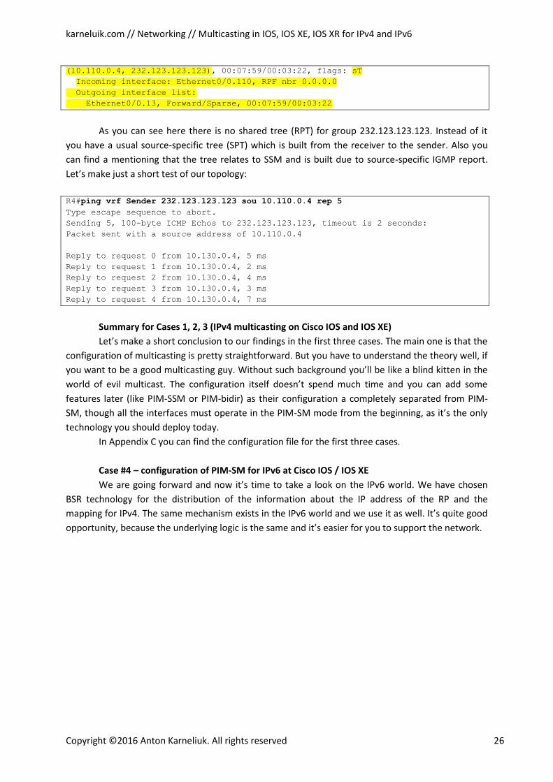
(10.110.0.4, 232.123.123.123), 00:07:59/00:03:22, flags: sT Incoming interface: Ethernet0/0.110, RPF nbr 0.0.0.0 Outgoing interface list:
Ethernet0/0.13, Forward/Sparse, 00:07:59/00:03:22
As you can see here there is no shared tree (RPT) for group 232.123.123.123. Instead of it
you have a usual source-specific tree (SPT) which is built from the receiver to the sender. Also you
can find a mentioning that the tree relates to SSM and is built due to source-specific IGMP report.
Let’s make just a short test of our topology:
R4#ping vrf Sender 232.123.123.123 sou 10.110.0.4 rep 5 Type escape sequence to abort.
Sending 5, 100-byte ICMP Echos to 232.123.123.123, timeout is 2 seconds:
Packet sent with a source address of 10.110.0.4
Reply to request 0 from 10.130.0.4, 5 ms
Reply to request 1 from 10.130.0.4, 2 ms
Reply to request 2 from 10.130.0.4, 4 ms
Reply to request 3 from 10.130.0.4, 3 ms
Reply to request 4 from 10.130.0.4, 7 ms
Summary for Cases 1, 2, 3 (IPv4 multicasting on Cisco IOS and IOS XE)
Let’s make a short conclusion to our findings in the first three cases. The main one is that the
configuration of multicasting is pretty straightforward. But you have to understand the theory well, if
you want to be a good multicasting guy. Without such background you’ll be like a blind kitten in the
world of evil multicast. The configuration itself doesn’t spend much time and you can add some
features later (like PIM-SSM or PIM-bidir) as their configuration a completely separated from PIM-
SM, though all the interfaces must operate in the PIM-SM mode from the beginning, as it’s the only
technology you should deploy today.
In Appendix C you can find the configuration file for the first three cases.
Case #4 – configuration of PIM-SM for IPv6 at Cisco IOS / IOS XE
We are going forward and now it’s time to take a look on the IPv6 world. We have chosen
BSR technology for the distribution of the information about the IP address of the RP and the
mapping for IPv4. The same mechanism exists in the IPv6 world and we use it as well. It’s quite good
opportunity, because the underlying logic is the same and it’s easier for you to support the network.
karneluik.com // Networking // Multicasting in IOS, IOS XE, IOS XR for IPv4 and IPv6
Copyright ©2016 Anton Karneliuk. All rights reserved 27
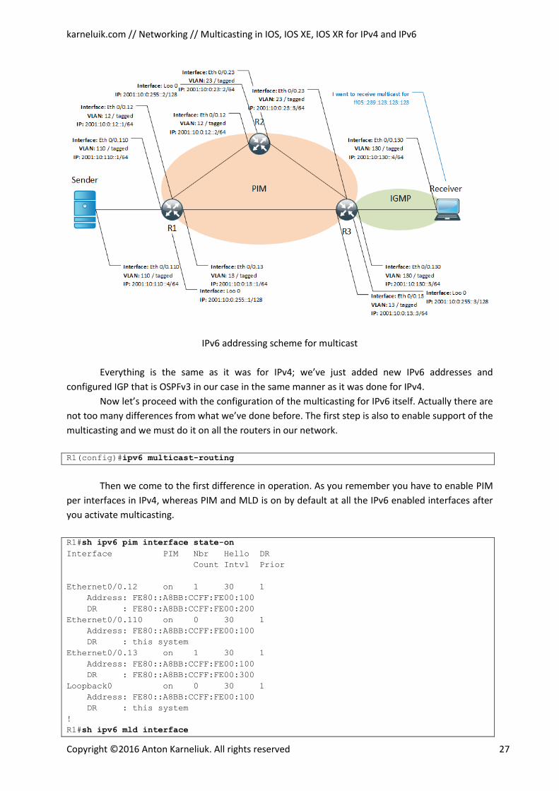
IPv6 addressing scheme for multicast
Everything is the same as it was for IPv4; we’ve just added new IPv6 addresses and
configured IGP that is OSPFv3 in our case in the same manner as it was done for IPv4.
Now let’s proceed with the configuration of the multicasting for IPv6 itself. Actually there are
not too many differences from what we’ve done before. The first step is also to enable support of the
multicasting and we must do it on all the routers in our network.
R1(config)#ipv6 multicast-routing
Then we come to the first difference in operation. As you remember you have to enable PIM
per interfaces in IPv4, whereas PIM and MLD is on by default at all the IPv6 enabled interfaces after
you activate multicasting.
R1#sh ipv6 pim interface state-on Interface PIM Nbr Hello DR
Count Intvl Prior
Ethernet0/0.12 on 1 30 1
Address: FE80::A8BB:CCFF:FE00:100
DR : FE80::A8BB:CCFF:FE00:200
Ethernet0/0.110 on 0 30 1
Address: FE80::A8BB:CCFF:FE00:100
DR : this system
Ethernet0/0.13 on 1 30 1
Address: FE80::A8BB:CCFF:FE00:100
DR : FE80::A8BB:CCFF:FE00:300
Loopback0 on 0 30 1
Address: FE80::A8BB:CCFF:FE00:100
DR : this system
!
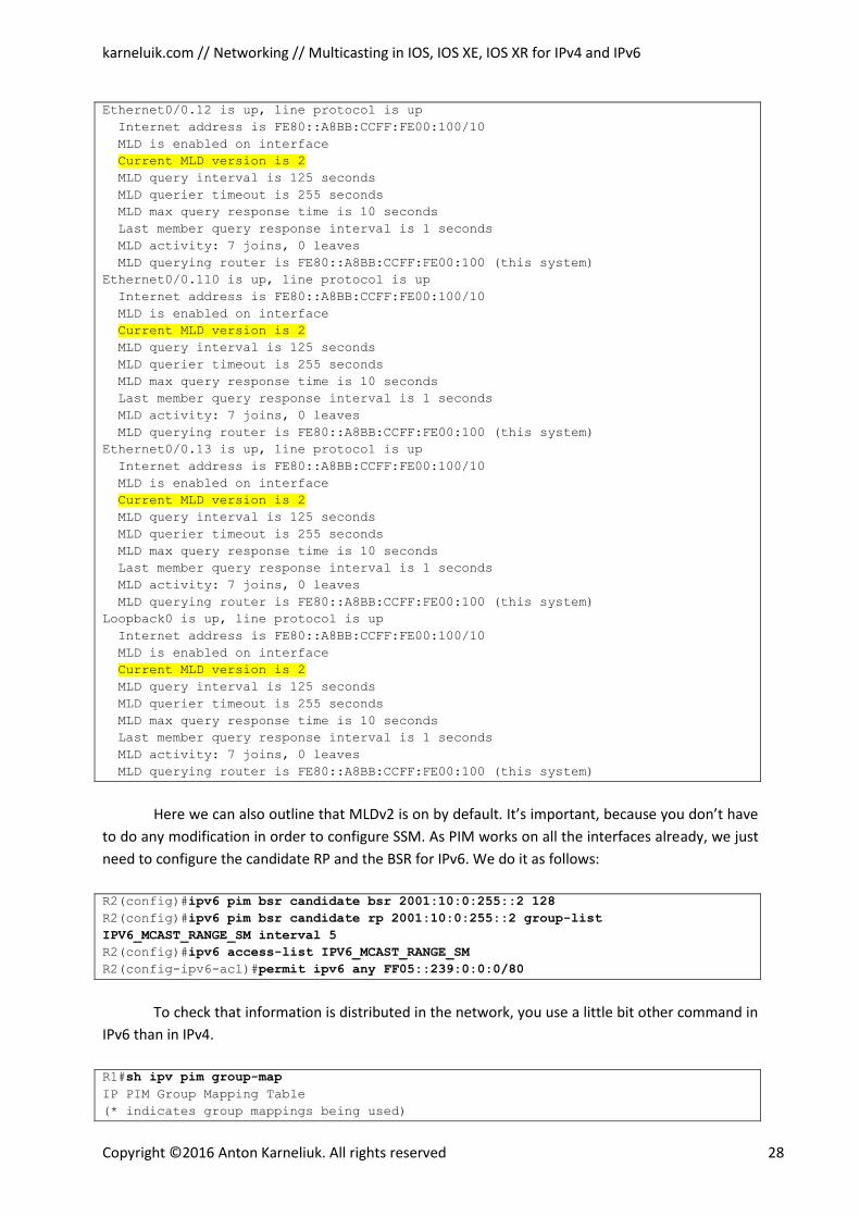
R1#sh ipv6 mld interface
karneluik.com // Networking // Multicasting in IOS, IOS XE, IOS XR for IPv4 and IPv6
Copyright ©2016 Anton Karneliuk. All rights reserved 28
Ethernet0/0.12 is up, line protocol is up
Internet address is FE80::A8BB:CCFF:FE00:100/10
MLD is enabled on interface
Current MLD version is 2 MLD query interval is 125 seconds
MLD querier timeout is 255 seconds
MLD max query response time is 10 seconds
Last member query response interval is 1 seconds
MLD activity: 7 joins, 0 leaves
MLD querying router is FE80::A8BB:CCFF:FE00:100 (this system)
Ethernet0/0.110 is up, line protocol is up
Internet address is FE80::A8BB:CCFF:FE00:100/10
MLD is enabled on interface
Current MLD version is 2 MLD query interval is 125 seconds
MLD querier timeout is 255 seconds
MLD max query response time is 10 seconds
Last member query response interval is 1 seconds
MLD activity: 7 joins, 0 leaves
MLD querying router is FE80::A8BB:CCFF:FE00:100 (this system)
Ethernet0/0.13 is up, line protocol is up
Internet address is FE80::A8BB:CCFF:FE00:100/10
MLD is enabled on interface
Current MLD version is 2 MLD query interval is 125 seconds
MLD querier timeout is 255 seconds
MLD max query response time is 10 seconds
Last member query response interval is 1 seconds
MLD activity: 7 joins, 0 leaves
MLD querying router is FE80::A8BB:CCFF:FE00:100 (this system)
Loopback0 is up, line protocol is up
Internet address is FE80::A8BB:CCFF:FE00:100/10
MLD is enabled on interface
Current MLD version is 2 MLD query interval is 125 seconds
MLD querier timeout is 255 seconds
MLD max query response time is 10 seconds
Last member query response interval is 1 seconds
MLD activity: 7 joins, 0 leaves
MLD querying router is FE80::A8BB:CCFF:FE00:100 (this system)
Here we can also outline that MLDv2 is on by default. It’s important, because you don’t have
to do any modification in order to configure SSM. As PIM works on all the interfaces already, we just
need to configure the candidate RP and the BSR for IPv6. We do it as follows:
R2(config)#ipv6 pim bsr candidate bsr 2001:10:0:255::2 128 R2(config)#ipv6 pim bsr candidate rp 2001:10:0:255::2 group-list
IPV6_MCAST_RANGE_SM interval 5 R2(config)#ipv6 access-list IPV6_MCAST_RANGE_SM R2(config-ipv6-acl)#permit ipv6 any FF05::239:0:0:0/80
To check that information is distributed in the network, you use a little bit other command in
IPv6 than in IPv4.
R1#sh ipv pim group-map IP PIM Group Mapping Table
(* indicates group mappings being used)
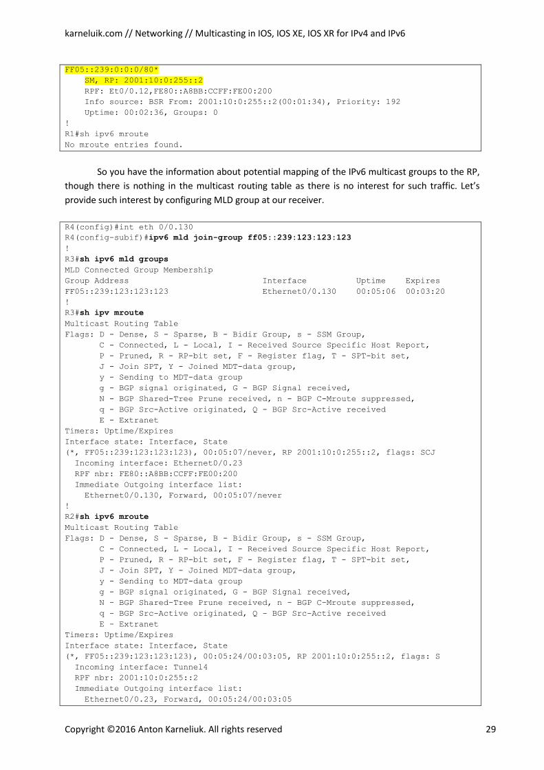
karneluik.com // Networking // Multicasting in IOS, IOS XE, IOS XR for IPv4 and IPv6
Copyright ©2016 Anton Karneliuk. All rights reserved 29
FF05::239:0:0:0/80* SM, RP: 2001:10:0:255::2 RPF: Et0/0.12,FE80::A8BB:CCFF:FE00:200
Info source: BSR From: 2001:10:0:255::2(00:01:34), Priority: 192
Uptime: 00:02:36, Groups: 0
!
R1#sh ipv6 mroute
No mroute entries found.
So you have the information about potential mapping of the IPv6 multicast groups to the RP,
though there is nothing in the multicast routing table as there is no interest for such traffic. Let’s
provide such interest by configuring MLD group at our receiver.
R4(config)#int eth 0/0.130
R4(config-subif)#ipv6 mld join-group ff05::239:123:123:123 !
R3#sh ipv6 mld groups MLD Connected Group Membership
Group Address Interface Uptime Expires
FF05::239:123:123:123 Ethernet0/0.130 00:05:06 00:03:20
!
R3#sh ipv mroute Multicast Routing Table
Flags: D - Dense, S - Sparse, B - Bidir Group, s - SSM Group,
C - Connected, L - Local, I - Received Source Specific Host Report,
P - Pruned, R - RP-bit set, F - Register flag, T - SPT-bit set,
J - Join SPT, Y - Joined MDT-data group,
y - Sending to MDT-data group
g - BGP signal originated, G - BGP Signal received,
N - BGP Shared-Tree Prune received, n - BGP C-Mroute suppressed,
q - BGP Src-Active originated, Q - BGP Src-Active received
E - Extranet
Timers: Uptime/Expires
Interface state: Interface, State
(*, FF05::239:123:123:123), 00:05:07/never, RP 2001:10:0:255::2, flags: SCJ
Incoming interface: Ethernet0/0.23
RPF nbr: FE80::A8BB:CCFF:FE00:200
Immediate Outgoing interface list:
Ethernet0/0.130, Forward, 00:05:07/never
!
R2#sh ipv6 mroute Multicast Routing Table
Flags: D - Dense, S - Sparse, B - Bidir Group, s - SSM Group,
C - Connected, L - Local, I - Received Source Specific Host Report,
P - Pruned, R - RP-bit set, F - Register flag, T - SPT-bit set,
J - Join SPT, Y - Joined MDT-data group,
y - Sending to MDT-data group
g - BGP signal originated, G - BGP Signal received,
N - BGP Shared-Tree Prune received, n - BGP C-Mroute suppressed,
q - BGP Src-Active originated, Q - BGP Src-Active received
E - Extranet
Timers: Uptime/Expires
Interface state: Interface, State
(*, FF05::239:123:123:123), 00:05:24/00:03:05, RP 2001:10:0:255::2, flags: S
Incoming interface: Tunnel4
RPF nbr: 2001:10:0:255::2
Immediate Outgoing interface list:
Ethernet0/0.23, Forward, 00:05:24/00:03:05
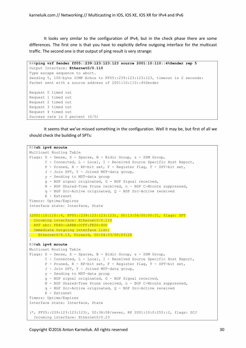
karneluik.com // Networking // Multicasting in IOS, IOS XE, IOS XR for IPv4 and IPv6
Copyright ©2016 Anton Karneliuk. All rights reserved 30
It looks very similar to the configuration of IPv4, but in the check phase there are some
differences. The first one is that you have to explicitly define outgoing interface for the multicast
traffic. The second one is that output of ping result is very strange:
R4#ping vrf Sender ff05::239:123:123:123 source 2001:10:110::4%Sender rep 5 Output Interface: Ethernet0/0.110
Type escape sequence to abort. Sending 5, 100-byte ICMP Echos to FF05::239:123:123:123, timeout is 2 seconds:
Packet sent with a source address of 2001:10:110::4%Sender
Request 0 timed out
Request 1 timed out
Request 2 timed out
Request 3 timed out
Request 4 timed out
Success rate is 0 percent (0/5)
It seems that we’ve missed something in the configuration. Well it may be, but first of all we
should check the building of SPTs:
R1#sh ipv6 mroute Multicast Routing Table
Flags: D - Dense, S - Sparse, B - Bidir Group, s - SSM Group,
C - Connected, L - Local, I - Received Source Specific Host Report,
P - Pruned, R - RP-bit set, F - Register flag, T - SPT-bit set,
J - Join SPT, Y - Joined MDT-data group,
y - Sending to MDT-data group
g - BGP signal originated, G - BGP Signal received,
N - BGP Shared-Tree Prune received, n - BGP C-Mroute suppressed,
q - BGP Src-Active originated, Q - BGP Src-Active received
E - Extranet
Timers: Uptime/Expires
Interface state: Interface, State
(2001:10:110::4, FF05::239:123:123:123), 00:13:56/00:00:31, flags: SFT
Incoming interface: Ethernet0/0.110
RPF nbr: FE80::A8BB:CCFF:FE00:400
Immediate Outgoing interface list:
Ethernet0/0.13, Forward, 00:04:03/00:03:26 !
R3#sh ipv6 mroute Multicast Routing Table
Flags: D - Dense, S - Sparse, B - Bidir Group, s - SSM Group,
C - Connected, L - Local, I - Received Source Specific Host Report,
P - Pruned, R - RP-bit set, F - Register flag, T - SPT-bit set,
J - Join SPT, Y - Joined MDT-data group,
y - Sending to MDT-data group
g - BGP signal originated, G - BGP Signal received,
N - BGP Shared-Tree Prune received, n - BGP C-Mroute suppressed,
q - BGP Src-Active originated, Q - BGP Src-Active received
E - Extranet
Timers: Uptime/Expires
Interface state: Interface, State
(*, FF05::239:123:123:123), 00:38:08/never, RP 2001:10:0:255::2, flags: SCJ
Incoming interface: Ethernet0/0.23
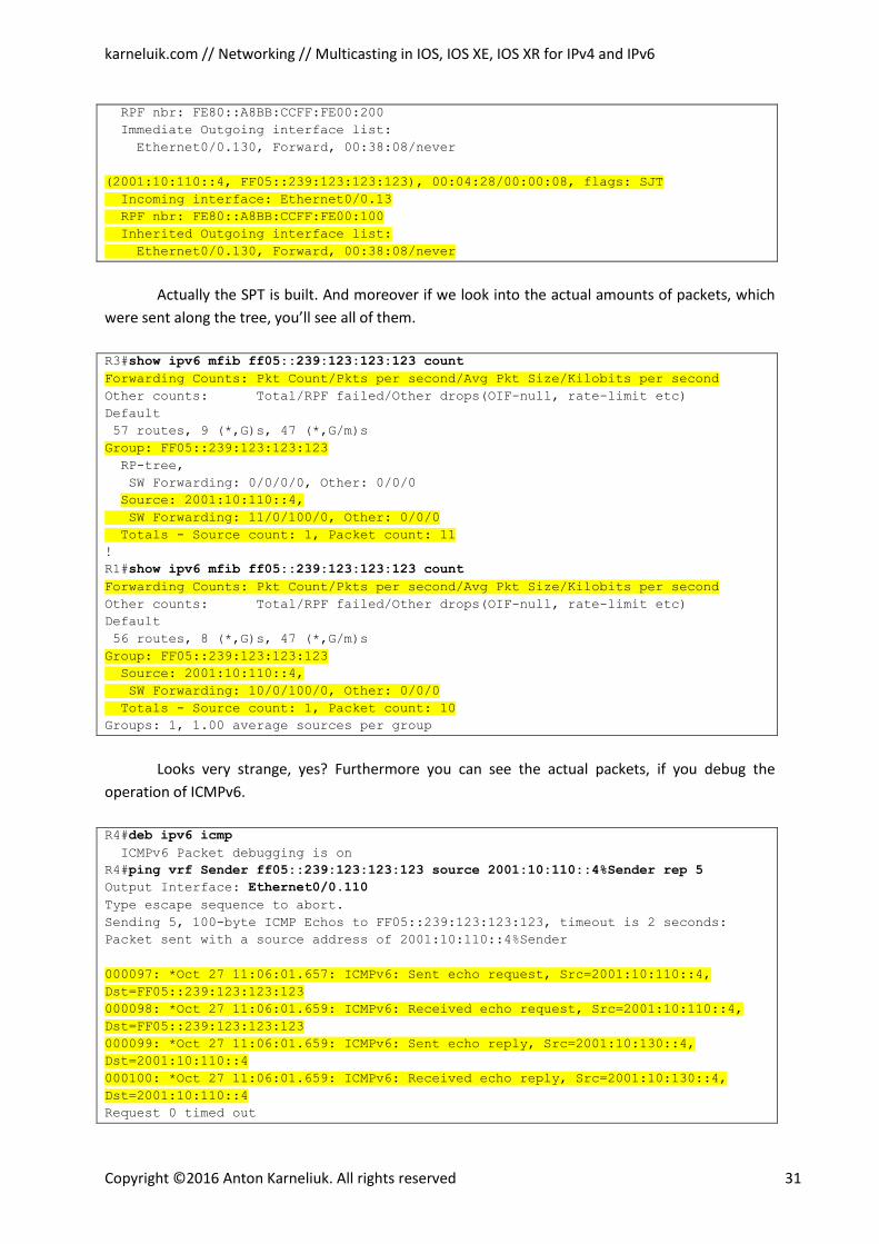
karneluik.com // Networking // Multicasting in IOS, IOS XE, IOS XR for IPv4 and IPv6
Copyright ©2016 Anton Karneliuk. All rights reserved 31
RPF nbr: FE80::A8BB:CCFF:FE00:200
Immediate Outgoing interface list:
Ethernet0/0.130, Forward, 00:38:08/never
(2001:10:110::4, FF05::239:123:123:123), 00:04:28/00:00:08, flags: SJT
Incoming interface: Ethernet0/0.13
RPF nbr: FE80::A8BB:CCFF:FE00:100
Inherited Outgoing interface list:
Ethernet0/0.130, Forward, 00:38:08/never
Actually the SPT is built. And moreover if we look into the actual amounts of packets, which
were sent along the tree, you’ll see all of them.
R3#show ipv6 mfib ff05::239:123:123:123 count Forwarding Counts: Pkt Count/Pkts per second/Avg Pkt Size/Kilobits per second Other counts: Total/RPF failed/Other drops(OIF-null, rate-limit etc)
Default
57 routes, 9 (*,G)s, 47 (*,G/m)s
Group: FF05::239:123:123:123 RP-tree,
SW Forwarding: 0/0/0/0, Other: 0/0/0
Source: 2001:10:110::4, SW Forwarding: 11/0/100/0, Other: 0/0/0
Totals - Source count: 1, Packet count: 11 !
R1#show ipv6 mfib ff05::239:123:123:123 count Forwarding Counts: Pkt Count/Pkts per second/Avg Pkt Size/Kilobits per second Other counts: Total/RPF failed/Other drops(OIF-null, rate-limit etc)
Default
56 routes, 8 (*,G)s, 47 (*,G/m)s
Group: FF05::239:123:123:123
Source: 2001:10:110::4,
SW Forwarding: 10/0/100/0, Other: 0/0/0
Totals - Source count: 1, Packet count: 10 Groups: 1, 1.00 average sources per group
Looks very strange, yes? Furthermore you can see the actual packets, if you debug the
operation of ICMPv6.
R4#deb ipv6 icmp ICMPv6 Packet debugging is on
R4#ping vrf Sender ff05::239:123:123:123 source 2001:10:110::4%Sender rep 5 Output Interface: Ethernet0/0.110
Type escape sequence to abort. Sending 5, 100-byte ICMP Echos to FF05::239:123:123:123, timeout is 2 seconds:
Packet sent with a source address of 2001:10:110::4%Sender
000097: *Oct 27 11:06:01.657: ICMPv6: Sent echo request, Src=2001:10:110::4,
Dst=FF05::239:123:123:123
000098: *Oct 27 11:06:01.659: ICMPv6: Received echo request, Src=2001:10:110::4,
Dst=FF05::239:123:123:123
000099: *Oct 27 11:06:01.659: ICMPv6: Sent echo reply, Src=2001:10:130::4,
Dst=2001:10:110::4
000100: *Oct 27 11:06:01.659: ICMPv6: Received echo reply, Src=2001:10:130::4,
Dst=2001:10:110::4 Request 0 timed out
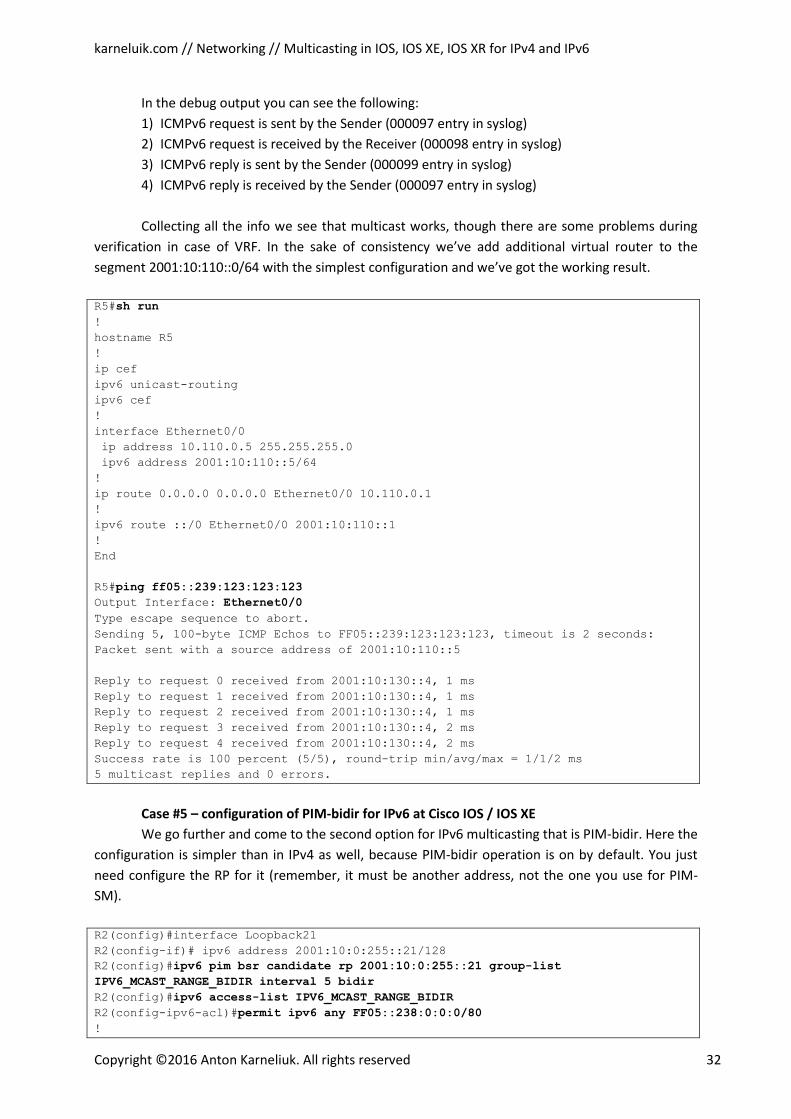
karneluik.com // Networking // Multicasting in IOS, IOS XE, IOS XR for IPv4 and IPv6
Copyright ©2016 Anton Karneliuk. All rights reserved 32
In the debug output you can see the following:
1) ICMPv6 request is sent by the Sender (000097 entry in syslog)
2) ICMPv6 request is received by the Receiver (000098 entry in syslog)
3) ICMPv6 reply is sent by the Sender (000099 entry in syslog)
4) ICMPv6 reply is received by the Sender (000097 entry in syslog)
Collecting all the info we see that multicast works, though there are some problems during
verification in case of VRF. In the sake of consistency we’ve add additional virtual router to the
segment 2001:10:110::0/64 with the simplest configuration and we’ve got the working result.
R5#sh run !
hostname R5
!
ip cef
ipv6 unicast-routing
ipv6 cef
!
interface Ethernet0/0
ip address 10.110.0.5 255.255.255.0
ipv6 address 2001:10:110::5/64
!
ip route 0.0.0.0 0.0.0.0 Ethernet0/0 10.110.0.1
!
ipv6 route ::/0 Ethernet0/0 2001:10:110::1
!
End
R5#ping ff05::239:123:123:123 Output Interface: Ethernet0/0 Type escape sequence to abort.
Sending 5, 100-byte ICMP Echos to FF05::239:123:123:123, timeout is 2 seconds:
Packet sent with a source address of 2001:10:110::5
Reply to request 0 received from 2001:10:130::4, 1 ms
Reply to request 1 received from 2001:10:130::4, 1 ms
Reply to request 2 received from 2001:10:130::4, 1 ms
Reply to request 3 received from 2001:10:130::4, 2 ms
Reply to request 4 received from 2001:10:130::4, 2 ms
Success rate is 100 percent (5/5), round-trip min/avg/max = 1/1/2 ms
5 multicast replies and 0 errors.
Case #5 – configuration of PIM-bidir for IPv6 at Cisco IOS / IOS XE
We go further and come to the second option for IPv6 multicasting that is PIM-bidir. Here the
configuration is simpler than in IPv4 as well, because PIM-bidir operation is on by default. You just
need configure the RP for it (remember, it must be another address, not the one you use for PIM-
SM).
R2(config)#interface Loopback21
R2(config-if)# ipv6 address 2001:10:0:255::21/128
R2(config)#ipv6 pim bsr candidate rp 2001:10:0:255::21 group-list
IPV6_MCAST_RANGE_BIDIR interval 5 bidir R2(config)#ipv6 access-list IPV6_MCAST_RANGE_BIDIR R2(config-ipv6-acl)#permit ipv6 any FF05::238:0:0:0/80 !
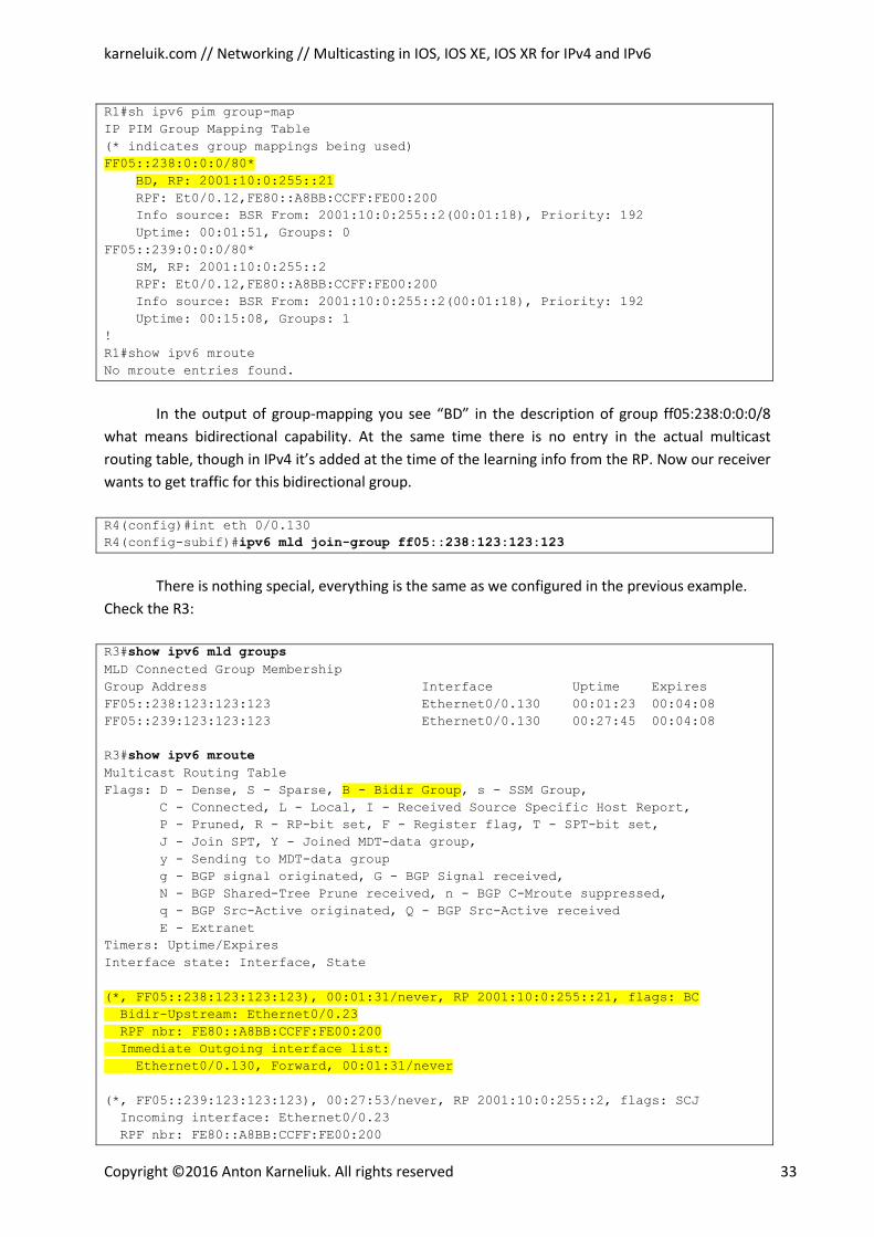
karneluik.com // Networking // Multicasting in IOS, IOS XE, IOS XR for IPv4 and IPv6
Copyright ©2016 Anton Karneliuk. All rights reserved 33
R1#sh ipv6 pim group-map
IP PIM Group Mapping Table
(* indicates group mappings being used)
FF05::238:0:0:0/80* BD, RP: 2001:10:0:255::21 RPF: Et0/0.12,FE80::A8BB:CCFF:FE00:200
Info source: BSR From: 2001:10:0:255::2(00:01:18), Priority: 192
Uptime: 00:01:51, Groups: 0
FF05::239:0:0:0/80*
SM, RP: 2001:10:0:255::2
RPF: Et0/0.12,FE80::A8BB:CCFF:FE00:200
Info source: BSR From: 2001:10:0:255::2(00:01:18), Priority: 192
Uptime: 00:15:08, Groups: 1
!
R1#show ipv6 mroute
No mroute entries found.
In the output of group-mapping you see “BD” in the description of group ff05:238:0:0:0/8
what means bidirectional capability. At the same time there is no entry in the actual multicast
routing table, though in IPv4 it’s added at the time of the learning info from the RP. Now our receiver
wants to get traffic for this bidirectional group.
R4(config)#int eth 0/0.130
R4(config-subif)#ipv6 mld join-group ff05::238:123:123:123
There is nothing special, everything is the same as we configured in the previous example.
Check the R3:
R3#show ipv6 mld groups MLD Connected Group Membership
Group Address Interface Uptime Expires
FF05::238:123:123:123 Ethernet0/0.130 00:01:23 00:04:08
FF05::239:123:123:123 Ethernet0/0.130 00:27:45 00:04:08
R3#show ipv6 mroute Multicast Routing Table
Flags: D - Dense, S - Sparse, B - Bidir Group, s - SSM Group, C - Connected, L - Local, I - Received Source Specific Host Report,
P - Pruned, R - RP-bit set, F - Register flag, T - SPT-bit set,
J - Join SPT, Y - Joined MDT-data group,
y - Sending to MDT-data group
g - BGP signal originated, G - BGP Signal received,
N - BGP Shared-Tree Prune received, n - BGP C-Mroute suppressed,
q - BGP Src-Active originated, Q - BGP Src-Active received
E - Extranet
Timers: Uptime/Expires
Interface state: Interface, State
(*, FF05::238:123:123:123), 00:01:31/never, RP 2001:10:0:255::21, flags: BC
Bidir-Upstream: Ethernet0/0.23
RPF nbr: FE80::A8BB:CCFF:FE00:200
Immediate Outgoing interface list:
Ethernet0/0.130, Forward, 00:01:31/never
(*, FF05::239:123:123:123), 00:27:53/never, RP 2001:10:0:255::2, flags: SCJ
Incoming interface: Ethernet0/0.23
RPF nbr: FE80::A8BB:CCFF:FE00:200
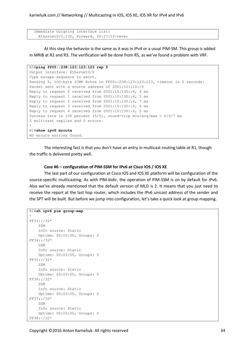
karneluik.com // Networking // Multicasting in IOS, IOS XE, IOS XR for IPv4 and IPv6
Copyright ©2016 Anton Karneliuk. All rights reserved 34
Immediate Outgoing interface list:
Ethernet0/0.130, Forward, 00:27:53/never
At this step the behavior is the same as it was in IPv4 or a usual PIM-SM. This group is added
in MRIB at R2 and R3. The verification will be done from R5, as we’ve found a problem with VRF.
R5#ping ff05::238:123:123:123 rep 5 Output Interface: Ethernet0/0
Type escape sequence to abort.
Sending 5, 100-byte ICMP Echos to FF05::238:123:123:123, timeout is 2 seconds:
Packet sent with a source address of 2001:10:110::5
Reply to request 0 received from 2001:10:130::4, 6 ms
Reply to request 1 received from 2001:10:130::4, 2 ms
Reply to request 2 received from 2001:10:130::4, 7 ms
Reply to request 3 received from 2001:10:130::4, 6 ms
Reply to request 4 received from 2001:10:130::4, 2 ms
Success rate is 100 percent (5/5), round-trip min/avg/max = 2/4/7 ms
5 multicast replies and 0 errors.
!
R1#show ipv6 mroute No mroute entries found.
The interesting fact is that you don’t have an entry in multicast routing table at R1, though
the traffic is delivered pretty well.
Case #6 – configuration of PIM-SSM for IPv6 at Cisco IOS / IOS XE
The last part of our configuration at Cisco IOS and IOS XE platform will be configuration of the
source-specific multicasting. As with PIM-bidir, the operation of PIM-SSM is on by default for IPv6.
Also we’ve already mentioned that the default version of MLD is 2. It means that you just need to
receive the report at the last hop router, which includes the IPv6 unicast address of the sender and
the SPT will be built. But before we jump into configuration, let’s take a quick look at group mapping.
R1#sh ipv6 pim group-map !
FF33::/32*
SSM
Info source: Static
Uptime: 00:03:00, Groups: 0
FF34::/32*
SSM
Info source: Static
Uptime: 00:03:00, Groups: 0
FF35::/32*
SSM
Info source: Static
Uptime: 00:03:00, Groups: 0
FF36::/32*
SSM
Info source: Static
Uptime: 00:03:00, Groups: 0
FF37::/32*
SSM
Info source: Static
Uptime: 00:03:00, Groups: 0
FF38::/32*
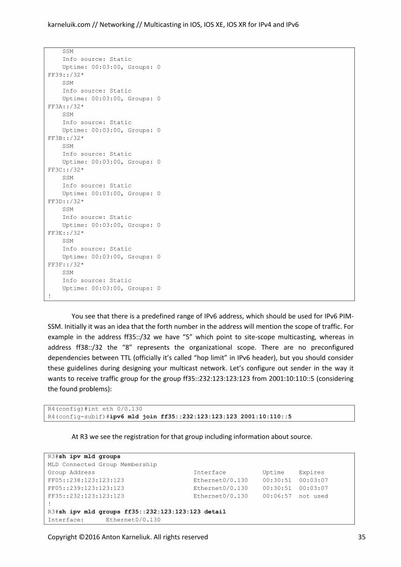
karneluik.com // Networking // Multicasting in IOS, IOS XE, IOS XR for IPv4 and IPv6
Copyright ©2016 Anton Karneliuk. All rights reserved 35
SSM
Info source: Static
Uptime: 00:03:00, Groups: 0
FF39::/32*
SSM
Info source: Static
Uptime: 00:03:00, Groups: 0
FF3A::/32*
SSM
Info source: Static
Uptime: 00:03:00, Groups: 0
FF3B::/32*
SSM
Info source: Static
Uptime: 00:03:00, Groups: 0
FF3C::/32*
SSM
Info source: Static
Uptime: 00:03:00, Groups: 0
FF3D::/32*
SSM
Info source: Static
Uptime: 00:03:00, Groups: 0
FF3E::/32*
SSM
Info source: Static
Uptime: 00:03:00, Groups: 0
FF3F::/32*
SSM
Info source: Static
Uptime: 00:03:00, Groups: 0
!
You see that there is a predefined range of IPv6 address, which should be used for IPv6 PIM-
SSM. Initially it was an idea that the forth number in the address will mention the scope of traffic. For
example in the address ff35::/32 we have “5” which point to site-scope multicasting, whereas in
address ff38::/32 the “8” represents the organizational scope. There are no preconfigured
dependencies between TTL (officially it’s called “hop limit” in IPv6 header), but you should consider
these guidelines during designing your multicast network. Let’s configure out sender in the way it
wants to receive traffic group for the group ff35::232:123:123:123 from 2001:10:110::5 (considering
the found problems):
R4(config)#int eth 0/0.130
R4(config-subif)#ipv6 mld join ff35::232:123:123:123 2001:10:110::5
At R3 we see the registration for that group including information about source.
R3#sh ipv mld groups MLD Connected Group Membership
Group Address Interface Uptime Expires
FF05::238:123:123:123 Ethernet0/0.130 00:30:51 00:03:07
FF05::239:123:123:123 Ethernet0/0.130 00:30:51 00:03:07
FF35::232:123:123:123 Ethernet0/0.130 00:06:57 not used
!
R3#sh ipv mld groups ff35::232:123:123:123 detail Interface: Ethernet0/0.130
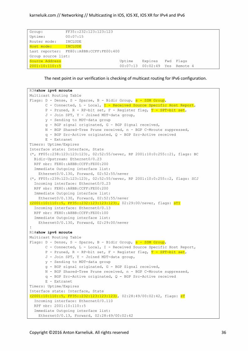
karneluik.com // Networking // Multicasting in IOS, IOS XE, IOS XR for IPv4 and IPv6
Copyright ©2016 Anton Karneliuk. All rights reserved 36
Group: FF35::232:123:123:123
Uptime: 00:07:15
Router mode: INCLUDE
Host mode: INCLUDE Last reporter: FE80::A8BB:CCFF:FE00:400
Group source list:
Source Address Uptime Expires Fwd Flags 2001:10:110::5 00:07:13 00:02:49 Yes Remote 4
The next point in our verification is checking of multicast routing for IPv6 configuration.
R3#show ipv6 mroute Multicast Routing Table
Flags: D - Dense, S - Sparse, B - Bidir Group, s - SSM Group, C - Connected, L - Local, I - Received Source Specific Host Report, P - Pruned, R - RP-bit set, F - Register flag, T - SPT-bit set, J - Join SPT, Y - Joined MDT-data group,
y - Sending to MDT-data group
g - BGP signal originated, G - BGP Signal received,
N - BGP Shared-Tree Prune received, n - BGP C-Mroute suppressed,
q - BGP Src-Active originated, Q - BGP Src-Active received
E - Extranet
Timers: Uptime/Expires
Interface state: Interface, State
(*, FF05::238:123:123:123), 02:52:55/never, RP 2001:10:0:255::21, flags: BC
Bidir-Upstream: Ethernet0/0.23
RPF nbr: FE80::A8BB:CCFF:FE00:200
Immediate Outgoing interface list:
Ethernet0/0.130, Forward, 02:52:55/never
(*, FF05::239:123:123:123), 02:52:55/never, RP 2001:10:0:255::2, flags: SCJ
Incoming interface: Ethernet0/0.23
RPF nbr: FE80::A8BB:CCFF:FE00:200
Immediate Outgoing interface list:
Ethernet0/0.130, Forward, 02:52:55/never
(2001:10:110::5, FF35::232:123:123:123), 02:29:00/never, flags: sTI Incoming interface: Ethernet0/0.13
RPF nbr: FE80::A8BB:CCFF:FE00:100
Immediate Outgoing interface list:
Ethernet0/0.130, Forward, 02:29:00/never
!
R1#show ipv6 mroute Multicast Routing Table
Flags: D - Dense, S - Sparse, B - Bidir Group, s - SSM Group, C - Connected, L - Local, I - Received Source Specific Host Report,
P - Pruned, R - RP-bit set, F - Register flag, T - SPT-bit set, J - Join SPT, Y - Joined MDT-data group,
y - Sending to MDT-data group
g - BGP signal originated, G - BGP Signal received,
N - BGP Shared-Tree Prune received, n - BGP C-Mroute suppressed,
q - BGP Src-Active originated, Q - BGP Src-Active received
E - Extranet
Timers: Uptime/Expires
Interface state: Interface, State
(2001:10:110::5, FF35::232:123:123:123), 02:28:49/00:02:42, flags: sT Incoming interface: Ethernet0/0.110
RPF nbr: 2001:10:110::5
Immediate Outgoing interface list:
Ethernet0/0.13, Forward, 02:28:49/00:02:42
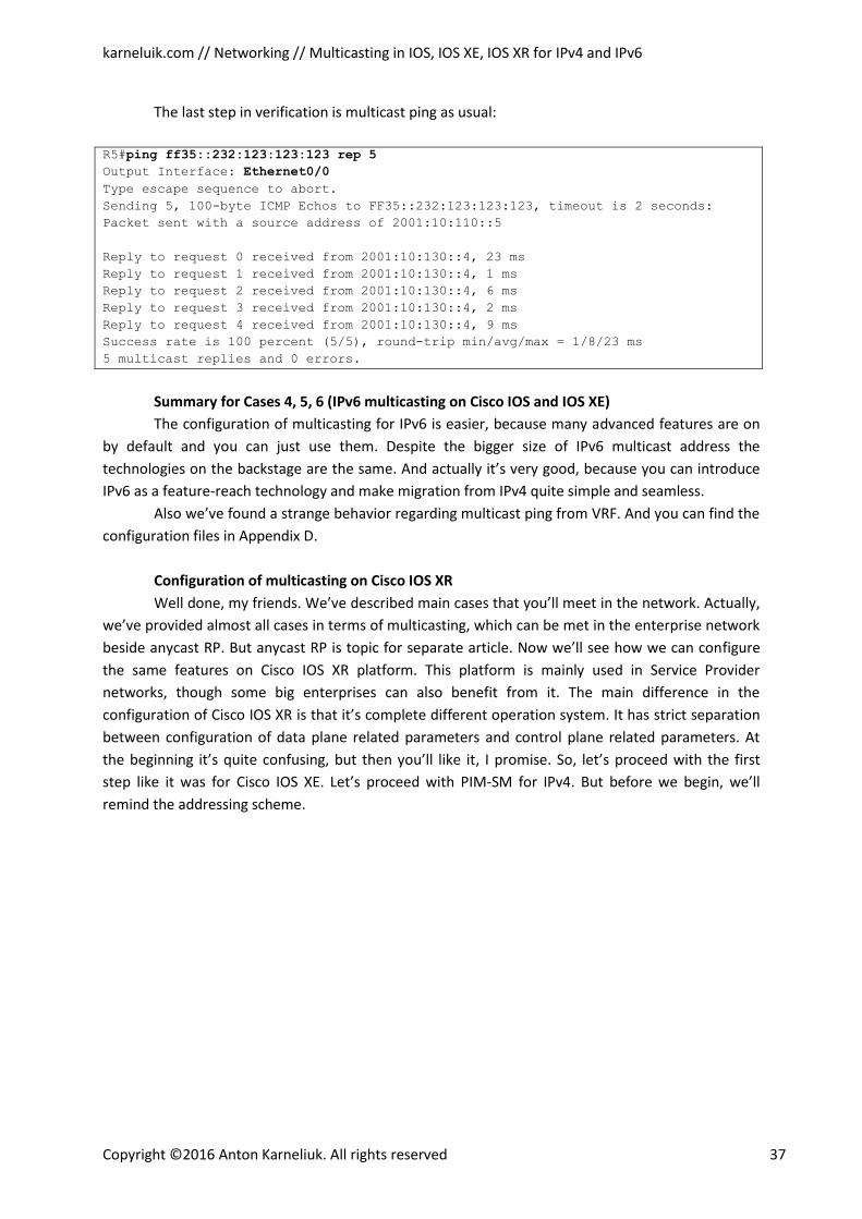
karneluik.com // Networking // Multicasting in IOS, IOS XE, IOS XR for IPv4 and IPv6
Copyright ©2016 Anton Karneliuk. All rights reserved 37
The last step in verification is multicast ping as usual:
R5#ping ff35::232:123:123:123 rep 5 Output Interface: Ethernet0/0 Type escape sequence to abort.
Sending 5, 100-byte ICMP Echos to FF35::232:123:123:123, timeout is 2 seconds:
Packet sent with a source address of 2001:10:110::5
Reply to request 0 received from 2001:10:130::4, 23 ms
Reply to request 1 received from 2001:10:130::4, 1 ms
Reply to request 2 received from 2001:10:130::4, 6 ms
Reply to request 3 received from 2001:10:130::4, 2 ms
Reply to request 4 received from 2001:10:130::4, 9 ms
Success rate is 100 percent (5/5), round-trip min/avg/max = 1/8/23 ms
5 multicast replies and 0 errors.
Summary for Cases 4, 5, 6 (IPv6 multicasting on Cisco IOS and IOS XE)
The configuration of multicasting for IPv6 is easier, because many advanced features are on
by default and you can just use them. Despite the bigger size of IPv6 multicast address the
technologies on the backstage are the same. And actually it’s very good, because you can introduce
IPv6 as a feature-reach technology and make migration from IPv4 quite simple and seamless.
Also we’ve found a strange behavior regarding multicast ping from VRF. And you can find the
configuration files in Appendix D.
Configuration of multicasting on Cisco IOS XR
Well done, my friends. We’ve described main cases that you’ll meet in the network. Actually,
we’ve provided almost all cases in terms of multicasting, which can be met in the enterprise network
beside anycast RP. But anycast RP is topic for separate article. Now we’ll see how we can configure
the same features on Cisco IOS XR platform. This platform is mainly used in Service Provider
networks, though some big enterprises can also benefit from it. The main difference in the
configuration of Cisco IOS XR is that it’s complete different operation system. It has strict separation
between configuration of data plane related parameters and control plane related parameters. At
the beginning it’s quite confusing, but then you’ll like it, I promise. So, let’s proceed with the first
step like it was for Cisco IOS XE. Let’s proceed with PIM-SM for IPv4. But before we begin, we’ll
remind the addressing scheme.
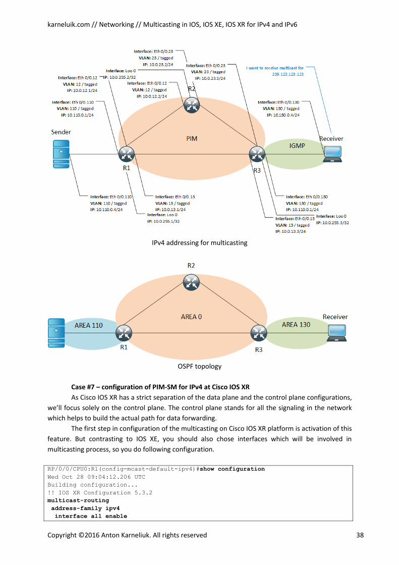
karneluik.com // Networking // Multicasting in IOS, IOS XE, IOS XR for IPv4 and IPv6
Copyright ©2016 Anton Karneliuk. All rights reserved 38
IPv4 addressing for multicasting
OSPF topology
Case #7 – configuration of PIM-SM for IPv4 at Cisco IOS XR
As Cisco IOS XR has a strict separation of the data plane and the control plane configurations,
we’ll focus solely on the control plane. The control plane stands for all the signaling in the network
which helps to build the actual path for data forwarding.
The first step in configuration of the multicasting on Cisco IOS XR platform is activation of this
feature. But contrasting to IOS XE, you should also chose interfaces which will be involved in
multicasting process, so you do following configuration.
RP/0/0/CPU0:R1(config-mcast-default-ipv4)#show configuration
Wed Oct 28 09:04:12.206 UTC
Building configuration...
!! IOS XR Configuration 5.3.2
multicast-routing
address-family ipv4
interface all enable
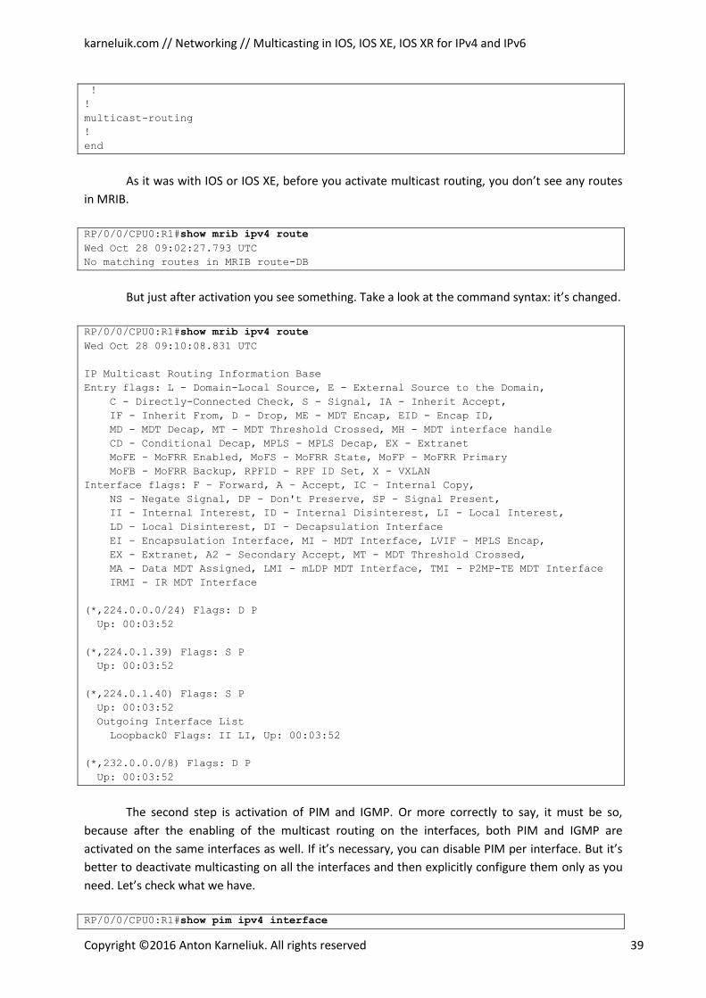
karneluik.com // Networking // Multicasting in IOS, IOS XE, IOS XR for IPv4 and IPv6
Copyright ©2016 Anton Karneliuk. All rights reserved 39
!
!
multicast-routing
!
end
As it was with IOS or IOS XE, before you activate multicast routing, you don’t see any routes
in MRIB.
RP/0/0/CPU0:R1#show mrib ipv4 route
Wed Oct 28 09:02:27.793 UTC
No matching routes in MRIB route-DB
But just after activation you see something. Take a look at the command syntax: it’s changed.
RP/0/0/CPU0:R1#show mrib ipv4 route
Wed Oct 28 09:10:08.831 UTC
IP Multicast Routing Information Base
Entry flags: L - Domain-Local Source, E - External Source to the Domain,
C - Directly-Connected Check, S - Signal, IA - Inherit Accept,
IF - Inherit From, D - Drop, ME - MDT Encap, EID - Encap ID,
MD - MDT Decap, MT - MDT Threshold Crossed, MH - MDT interface handle
CD - Conditional Decap, MPLS - MPLS Decap, EX - Extranet
MoFE - MoFRR Enabled, MoFS - MoFRR State, MoFP - MoFRR Primary
MoFB - MoFRR Backup, RPFID - RPF ID Set, X - VXLAN
Interface flags: F - Forward, A - Accept, IC - Internal Copy,
NS - Negate Signal, DP - Don't Preserve, SP - Signal Present,
II - Internal Interest, ID - Internal Disinterest, LI - Local Interest,
LD - Local Disinterest, DI - Decapsulation Interface
EI - Encapsulation Interface, MI - MDT Interface, LVIF - MPLS Encap,
EX - Extranet, A2 - Secondary Accept, MT - MDT Threshold Crossed,
MA - Data MDT Assigned, LMI - mLDP MDT Interface, TMI - P2MP-TE MDT Interface
IRMI - IR MDT Interface
(*,224.0.0.0/24) Flags: D P
Up: 00:03:52
(*,224.0.1.39) Flags: S P
Up: 00:03:52
(*,224.0.1.40) Flags: S P
Up: 00:03:52
Outgoing Interface List
Loopback0 Flags: II LI, Up: 00:03:52
(*,232.0.0.0/8) Flags: D P
Up: 00:03:52
The second step is activation of PIM and IGMP. Or more correctly to say, it must be so,
because after the enabling of the multicast routing on the interfaces, both PIM and IGMP are
activated on the same interfaces as well. If it’s necessary, you can disable PIM per interface. But it’s
better to deactivate multicasting on all the interfaces and then explicitly configure them only as you
need. Let’s check what we have.
RP/0/0/CPU0:R1#show pim ipv4 interface
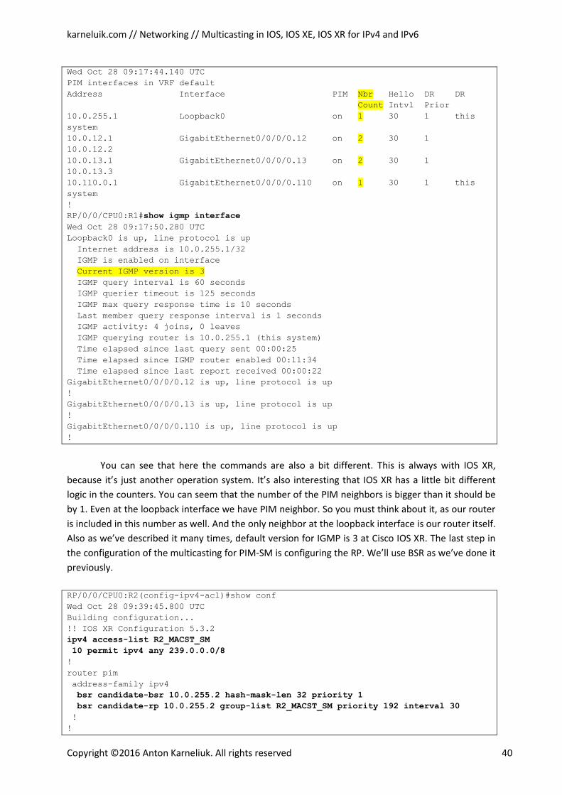
karneluik.com // Networking // Multicasting in IOS, IOS XE, IOS XR for IPv4 and IPv6
Copyright ©2016 Anton Karneliuk. All rights reserved 40
Wed Oct 28 09:17:44.140 UTC
PIM interfaces in VRF default
Address Interface PIM Nbr Hello DR DR
Count Intvl Prior
10.0.255.1 Loopback0 on 1 30 1 this
system
10.0.12.1 GigabitEthernet0/0/0/0.12 on 2 30 1
10.0.12.2
10.0.13.1 GigabitEthernet0/0/0/0.13 on 2 30 1
10.0.13.3
10.110.0.1 GigabitEthernet0/0/0/0.110 on 1 30 1 this
system
!
RP/0/0/CPU0:R1#show igmp interface
Wed Oct 28 09:17:50.280 UTC
Loopback0 is up, line protocol is up
Internet address is 10.0.255.1/32
IGMP is enabled on interface
Current IGMP version is 3
IGMP query interval is 60 seconds
IGMP querier timeout is 125 seconds
IGMP max query response time is 10 seconds
Last member query response interval is 1 seconds
IGMP activity: 4 joins, 0 leaves
IGMP querying router is 10.0.255.1 (this system)
Time elapsed since last query sent 00:00:25
Time elapsed since IGMP router enabled 00:11:34
Time elapsed since last report received 00:00:22
GigabitEthernet0/0/0/0.12 is up, line protocol is up
!
GigabitEthernet0/0/0/0.13 is up, line protocol is up
!
GigabitEthernet0/0/0/0.110 is up, line protocol is up
!
You can see that here the commands are also a bit different. This is always with IOS XR,
because it’s just another operation system. It’s also interesting that IOS XR has a little bit different
logic in the counters. You can seem that the number of the PIM neighbors is bigger than it should be
by 1. Even at the loopback interface we have PIM neighbor. So you must think about it, as our router
is included in this number as well. And the only neighbor at the loopback interface is our router itself.
Also as we’ve described it many times, default version for IGMP is 3 at Cisco IOS XR. The last step in
the configuration of the multicasting for PIM-SM is configuring the RP. We’ll use BSR as we’ve done it
previously.
RP/0/0/CPU0:R2(config-ipv4-acl)#show conf
Wed Oct 28 09:39:45.800 UTC
Building configuration...
!! IOS XR Configuration 5.3.2
ipv4 access-list R2_MACST_SM
10 permit ipv4 any 239.0.0.0/8
!
router pim
address-family ipv4
bsr candidate-bsr 10.0.255.2 hash-mask-len 32 priority 1
bsr candidate-rp 10.0.255.2 group-list R2_MACST_SM priority 192 interval 30
!
!
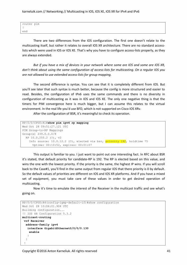
karneluik.com // Networking // Multicasting in IOS, IOS XE, IOS XR for IPv4 and IPv6
Copyright ©2016 Anton Karneliuk. All rights reserved 41
router pim
!
end
There are two differences from the IOS configuration. The first one doesn’t relate to the
multicasting itself, but rather it relates to overall IOS XR architecture. There are no standard access-
lists which were used in IOS or IOS XE. That’s why you have to configure access-lists properly, as they
are always extended.
But if you have a mix of devices in your network where some are IOS and some are IOS XR,
don’t think about using the same configuration of access-lists for multicasting. On a regular IOS you
are not allowed to use extended access-lists for group mapping.
The second difference is syntax. You can see that it is completely different from IOS. But
you’ll see later that such syntax is much better, because the config is more structured and easier to
read. Besides, the configuration of IPv6 uses the same commands and there is no diversity in
configuration of multicasting as it was in IOS and IOS XE. The only one negative thing is that the
timers for PIM convergence here is much bigger, but I can assume this relates to the virtual
environment. In the real life you’d use BFD, which is not supported on Cisco IOS XRv.
After the configuration of BSR, it’s meaningful to check its operation.
RP/0/0/CPU0:R1#show pim ipv4 rp mapping
Wed Oct 28 09:51:27.121 UTC
PIM Group-to-RP Mappings
Group(s) 239.0.0.0/8
RP 10.0.255.2 (?), v2
Info source: 10.0.12.2 (?), elected via bsr, priority 192, holdtime 75
Uptime: 00:10:52, expires: 00:01:07
This output is familiar to you. I just want to point out one interesting fact. In RFC about BSR
it’s stated, that default priority for candidate-RP is 192. The RP is elected based on this value, and
wins the one with the lowest priority. If the priority is the same, the highest IP wins. If you will scroll
back to the Case#1, you’ll find in the same output from regular IOS that there priority is 0 by default.
So the default values of priorities are different on IOS and IOS XR platforms. And if you have a mixed
set of equipment, you must take care of these values in order to get desired operation of
multicasting.
Now it’s time to emulate the interest of the Receiver in the multicast traffic and see what’s
going on.
RP/0/0/CPU0:R4(config-igmp-default-if)#show configuration
Wed Oct 28 10:06:01.904 UTC
Building configuration...
!! IOS XR Configuration 5.3.2
multicast-routing
vrf Receiver
address-family ipv4
interface GigabitEthernet0/0/0/0.130
enable
!
!
!
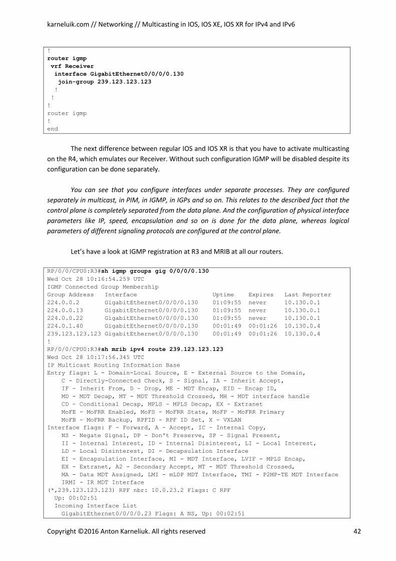
karneluik.com // Networking // Multicasting in IOS, IOS XE, IOS XR for IPv4 and IPv6
Copyright ©2016 Anton Karneliuk. All rights reserved 42
!
router igmp
vrf Receiver
interface GigabitEthernet0/0/0/0.130
join-group 239.123.123.123
!
!
!
router igmp
!
end
The next difference between regular IOS and IOS XR is that you have to activate multicasting
on the R4, which emulates our Receiver. Without such configuration IGMP will be disabled despite its
configuration can be done separately.
You can see that you configure interfaces under separate processes. They are configured
separately in multicast, in PIM, in IGMP, in IGPs and so on. This relates to the described fact that the
control plane is completely separated from the data plane. And the configuration of physical interface
parameters like IP, speed, encapsulation and so on is done for the data plane, whereas logical
parameters of different signaling protocols are configured at the control plane.
Let’s have a look at IGMP registration at R3 and MRIB at all our routers.
RP/0/0/CPU0:R3#sh igmp groups gig 0/0/0/0.130
Wed Oct 28 10:16:54.259 UTC
IGMP Connected Group Membership
Group Address Interface Uptime Expires Last Reporter
224.0.0.2 GigabitEthernet0/0/0/0.130 01:09:55 never 10.130.0.1
224.0.0.13 GigabitEthernet0/0/0/0.130 01:09:55 never 10.130.0.1
224.0.0.22 GigabitEthernet0/0/0/0.130 01:09:55 never 10.130.0.1
224.0.1.40 GigabitEthernet0/0/0/0.130 00:01:49 00:01:26 10.130.0.4
239.123.123.123 GigabitEthernet0/0/0/0.130 00:01:49 00:01:26 10.130.0.4
!
RP/0/0/CPU0:R3#sh mrib ipv4 route 239.123.123.123
Wed Oct 28 10:17:56.345 UTC
IP Multicast Routing Information Base
Entry flags: L - Domain-Local Source, E - External Source to the Domain,
C - Directly-Connected Check, S - Signal, IA - Inherit Accept,
IF - Inherit From, D - Drop, ME - MDT Encap, EID - Encap ID,
MD - MDT Decap, MT - MDT Threshold Crossed, MH - MDT interface handle
CD - Conditional Decap, MPLS - MPLS Decap, EX - Extranet
MoFE - MoFRR Enabled, MoFS - MoFRR State, MoFP - MoFRR Primary
MoFB - MoFRR Backup, RPFID - RPF ID Set, X - VXLAN
Interface flags: F - Forward, A - Accept, IC - Internal Copy,
NS - Negate Signal, DP - Don't Preserve, SP - Signal Present,
II - Internal Interest, ID - Internal Disinterest, LI - Local Interest,
LD - Local Disinterest, DI - Decapsulation Interface
EI - Encapsulation Interface, MI - MDT Interface, LVIF - MPLS Encap,
EX - Extranet, A2 - Secondary Accept, MT - MDT Threshold Crossed,
MA - Data MDT Assigned, LMI - mLDP MDT Interface, TMI - P2MP-TE MDT Interface
IRMI - IR MDT Interface
(*,239.123.123.123) RPF nbr: 10.0.23.2 Flags: C RPF
Up: 00:02:51
Incoming Interface List
GigabitEthernet0/0/0/0.23 Flags: A NS, Up: 00:02:51
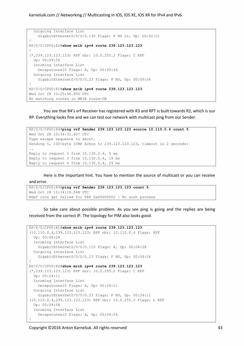
karneluik.com // Networking // Multicasting in IOS, IOS XE, IOS XR for IPv4 and IPv6
Copyright ©2016 Anton Karneliuk. All rights reserved 43
Outgoing Interface List
GigabitEthernet0/0/0/0.130 Flags: F NS LI, Up: 00:02:51
!
RP/0/0/CPU0:R2#show mrib ipv4 route 239.123.123.123
!
(*,239.123.123.123) RPF nbr: 10.0.255.2 Flags: C RPF
Up: 00:09:56
Incoming Interface List
Decapstunnel0 Flags: A, Up: 00:09:56
Outgoing Interface List
GigabitEthernet0/0/0/0.23 Flags: F NS, Up: 00:09:56
!
RP/0/0/CPU0:R1#show mrib ipv4 route 239.123.123.123
Wed Oct 28 10:25:46.930 UTC
No matching routes in MRIB route-DB
You see that R4’s vrf Receiver has registered with R3 and RPT is built towards R2, which is our
RP. Everything looks fine and we can test our network with multicast ping from our Sender.
RP/0/0/CPU0:R4#ping vrf Sender 239.123.123.123 source 10.110.0.4 count 5
Wed Oct 28 10:34:32.407 UTC
Type escape sequence to abort.
Sending 5, 100-byte ICMP Echos to 239.123.123.123, timeout is 2 seconds:
..
Reply to request 2 from 10.130.0.4, 9 ms
Reply to request 3 from 10.130.0.4, 19 ms
Reply to request 4 from 10.130.0.4, 29 ms
Here is the important hint. You have to mention the source of multicast or you can receive
and error. RP/0/0/CPU0:R4#ping vrf Sender 239.123.123.123 count 5
Wed Oct 28 10:34:16.548 UTC
Mdef cons get failed for VRF 0x60000002 - No such process
So take care about possible problem. As you see ping is going and the replies are being
received from the correct IP. The topology for PIM also looks good.
RP/0/0/CPU0:R1#show mrib ipv4 route 239.123.123.123
(10.110.0.4,239.123.123.123) RPF nbr: 10.110.0.4 Flags: RPF
Up: 00:04:28
Incoming Interface List
GigabitEthernet0/0/0/0.110 Flags: A, Up: 00:04:28
Outgoing Interface List
GigabitEthernet0/0/0/0.13 Flags: F NS, Up: 00:04:24
!
RP/0/0/CPU0:R2#show mrib ipv4 route 239.123.123.123
(*,239.123.123.123) RPF nbr: 10.0.255.2 Flags: C RPF
Up: 00:24:11
Incoming Interface List
Decapstunnel0 Flags: A, Up: 00:24:11
Outgoing Interface List
GigabitEthernet0/0/0/0.23 Flags: F NS, Up: 00:24:11
(10.110.0.4,239.123.123.123) RPF nbr: 10.0.255.2 Flags: L RPF
Up: 00:04:58
Incoming Interface List
Decapstunnel0 Flags: A, Up: 00:04:54
!
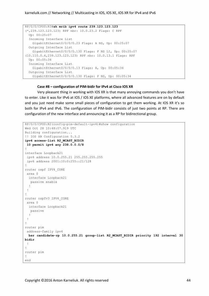
karneluik.com // Networking // Multicasting in IOS, IOS XE, IOS XR for IPv4 and IPv6
Copyright ©2016 Anton Karneliuk. All rights reserved 44
RP/0/0/CPU0:R3#sh mrib ipv4 route 239.123.123.123
(*,239.123.123.123) RPF nbr: 10.0.23.2 Flags: C RPF
Up: 00:25:07
Incoming Interface List
GigabitEthernet0/0/0/0.23 Flags: A NS, Up: 00:25:07
Outgoing Interface List
GigabitEthernet0/0/0/0.130 Flags: F NS LI, Up: 00:25:07
(10.110.0.4,239.123.123.123) RPF nbr: 10.0.13.1 Flags: RPF
Up: 00:05:34
Incoming Interface List
GigabitEthernet0/0/0/0.13 Flags: A, Up: 00:05:34
Outgoing Interface List
GigabitEthernet0/0/0/0.130 Flags: F NS, Up: 00:05:34
Case #8 – configuration of PIM-bidir for IPv4 at Cisco IOS XR
Very pleasant thing in working with IOS XR is that many annoying commands you don’t have
to enter. Like it was for IPv6 at IOS / IOS XE platforms, where all advanced features are on by default
and you just need make some small pieces of configuration to get them working. At IOS XR it’s so
both for IPv4 and IPv6. The configuration of PIM-bidir consists of just two points at RP. There are
configuration of the new interface and announcing it as a RP for bidirectional group.
RP/0/0/CPU0:R2(config-pim-default-ipv4)#show configuration
Wed Oct 28 10:48:07.919 UTC
Building configuration...
!! IOS XR Configuration 5.3.2
ipv4 access-list R2_MCAST_BIDIR
10 permit ipv4 any 238.0.0.0/8
!
interface Loopback21
ipv4 address 10.0.255.21 255.255.255.255
ipv6 address 2001:10:0:255::21/128
!
router ospf IPV4_CORE
area 0
interface Loopback21
passive enable
!
!
!
router ospfv3 IPV6_CORE
area 0
interface Loopback21
passive
!
!
!
router pim
address-family ipv4
bsr candidate-rp 10.0.255.21 group-list R2_MCAST_BIDIR priority 192 interval 30
bidir
!
!
router pim
!
end
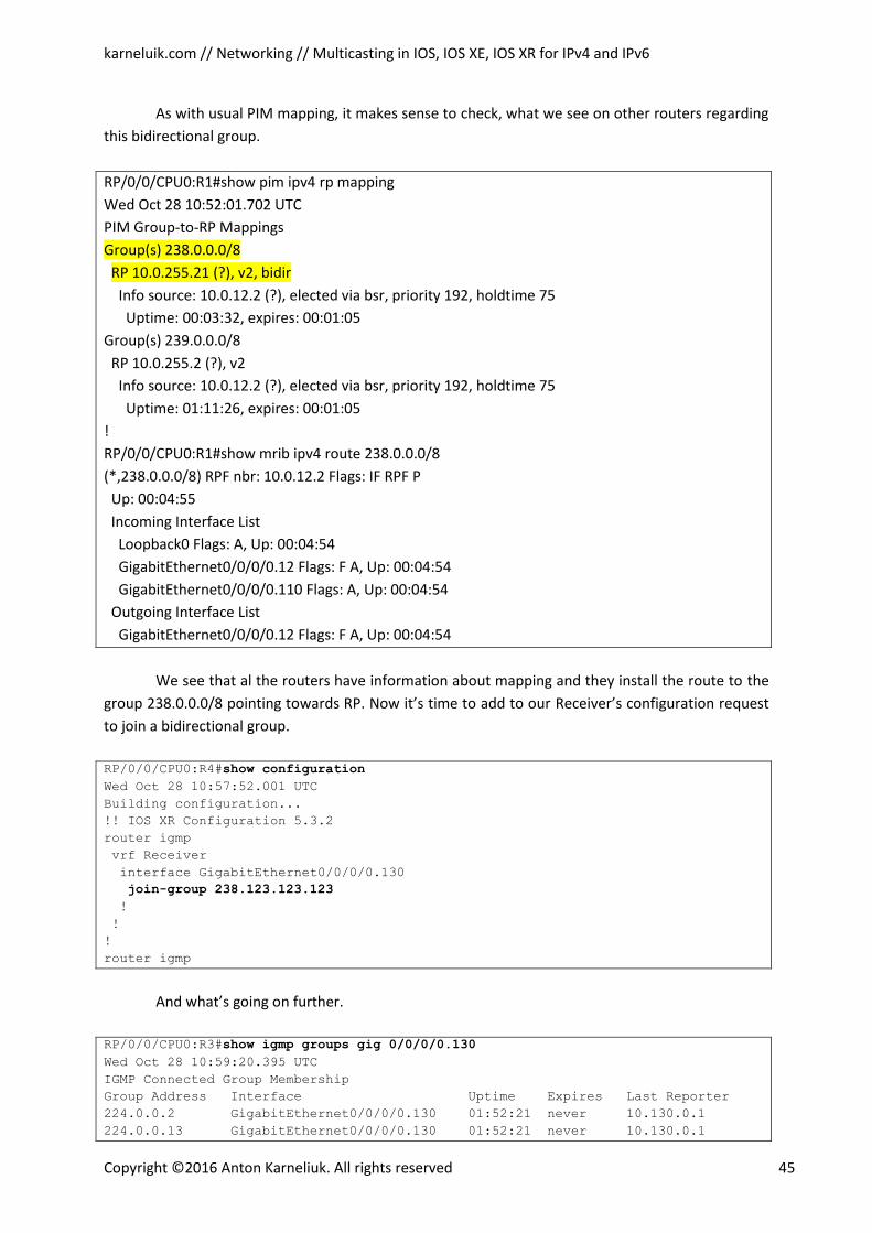
karneluik.com // Networking // Multicasting in IOS, IOS XE, IOS XR for IPv4 and IPv6
Copyright ©2016 Anton Karneliuk. All rights reserved 45
As with usual PIM mapping, it makes sense to check, what we see on other routers regarding
this bidirectional group.
RP/0/0/CPU0:R1#show pim ipv4 rp mapping
Wed Oct 28 10:52:01.702 UTC
PIM Group-to-RP Mappings
Group(s) 238.0.0.0/8
RP 10.0.255.21 (?), v2, bidir
Info source: 10.0.12.2 (?), elected via bsr, priority 192, holdtime 75
Uptime: 00:03:32, expires: 00:01:05
Group(s) 239.0.0.0/8
RP 10.0.255.2 (?), v2
Info source: 10.0.12.2 (?), elected via bsr, priority 192, holdtime 75
Uptime: 01:11:26, expires: 00:01:05
!
RP/0/0/CPU0:R1#show mrib ipv4 route 238.0.0.0/8
(*,238.0.0.0/8) RPF nbr: 10.0.12.2 Flags: IF RPF P
Up: 00:04:55
Incoming Interface List
Loopback0 Flags: A, Up: 00:04:54
GigabitEthernet0/0/0/0.12 Flags: F A, Up: 00:04:54
GigabitEthernet0/0/0/0.110 Flags: A, Up: 00:04:54
Outgoing Interface List
GigabitEthernet0/0/0/0.12 Flags: F A, Up: 00:04:54
We see that al the routers have information about mapping and they install the route to the
group 238.0.0.0/8 pointing towards RP. Now it’s time to add to our Receiver’s configuration request
to join a bidirectional group.
RP/0/0/CPU0:R4#show configuration
Wed Oct 28 10:57:52.001 UTC
Building configuration...
!! IOS XR Configuration 5.3.2
router igmp
vrf Receiver
interface GigabitEthernet0/0/0/0.130
join-group 238.123.123.123
!
!
!
router igmp
And what’s going on further.
RP/0/0/CPU0:R3#show igmp groups gig 0/0/0/0.130
Wed Oct 28 10:59:20.395 UTC
IGMP Connected Group Membership
Group Address Interface Uptime Expires Last Reporter
224.0.0.2 GigabitEthernet0/0/0/0.130 01:52:21 never 10.130.0.1
224.0.0.13 GigabitEthernet0/0/0/0.130 01:52:21 never 10.130.0.1
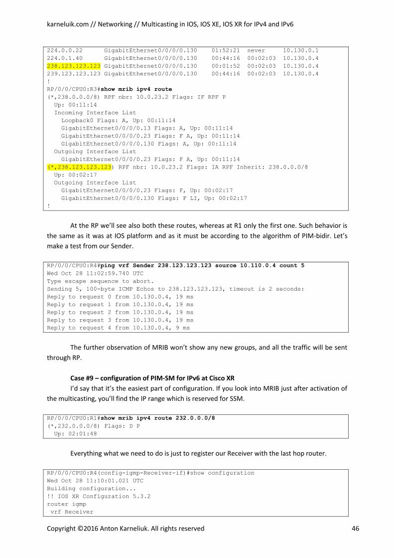
karneluik.com // Networking // Multicasting in IOS, IOS XE, IOS XR for IPv4 and IPv6
Copyright ©2016 Anton Karneliuk. All rights reserved 46
224.0.0.22 GigabitEthernet0/0/0/0.130 01:52:21 never 10.130.0.1
224.0.1.40 GigabitEthernet0/0/0/0.130 00:44:16 00:02:03 10.130.0.4
238.123.123.123 GigabitEthernet0/0/0/0.130 00:01:52 00:02:03 10.130.0.4
239.123.123.123 GigabitEthernet0/0/0/0.130 00:44:16 00:02:03 10.130.0.4
!
RP/0/0/CPU0:R3#show mrib ipv4 route
(*,238.0.0.0/8) RPF nbr: 10.0.23.2 Flags: IF RPF P
Up: 00:11:14
Incoming Interface List
Loopback0 Flags: A, Up: 00:11:14
GigabitEthernet0/0/0/0.13 Flags: A, Up: 00:11:14
GigabitEthernet0/0/0/0.23 Flags: F A, Up: 00:11:14
GigabitEthernet0/0/0/0.130 Flags: A, Up: 00:11:14
Outgoing Interface List
GigabitEthernet0/0/0/0.23 Flags: F A, Up: 00:11:14
(*,238.123.123.123) RPF nbr: 10.0.23.2 Flags: IA RPF Inherit: 238.0.0.0/8
Up: 00:02:17
Outgoing Interface List
GigabitEthernet0/0/0/0.23 Flags: F, Up: 00:02:17
GigabitEthernet0/0/0/0.130 Flags: F LI, Up: 00:02:17
!
At the RP we’ll see also both these routes, whereas at R1 only the first one. Such behavior is
the same as it was at IOS platform and as it must be according to the algorithm of PIM-bidir. Let’s
make a test from our Sender.
RP/0/0/CPU0:R4#ping vrf Sender 238.123.123.123 source 10.110.0.4 count 5
Wed Oct 28 11:02:59.740 UTC
Type escape sequence to abort.
Sending 5, 100-byte ICMP Echos to 238.123.123.123, timeout is 2 seconds:
Reply to request 0 from 10.130.0.4, 19 ms
Reply to request 1 from 10.130.0.4, 19 ms
Reply to request 2 from 10.130.0.4, 19 ms
Reply to request 3 from 10.130.0.4, 19 ms
Reply to request 4 from 10.130.0.4, 9 ms
The further observation of MRIB won’t show any new groups, and all the traffic will be sent
through RP.
Case #9 – configuration of PIM-SM for IPv6 at Cisco XR
I’d say that it’s the easiest part of configuration. If you look into MRIB just after activation of
the multicasting, you’ll find the IP range which is reserved for SSM.
RP/0/0/CPU0:R1#show mrib ipv4 route 232.0.0.0/8
(*,232.0.0.0/8) Flags: D P
Up: 02:01:48
Everything what we need to do is just to register our Receiver with the last hop router.
RP/0/0/CPU0:R4(config-igmp-Receiver-if)#show configuration
Wed Oct 28 11:10:01.021 UTC
Building configuration...
!! IOS XR Configuration 5.3.2
router igmp
vrf Receiver
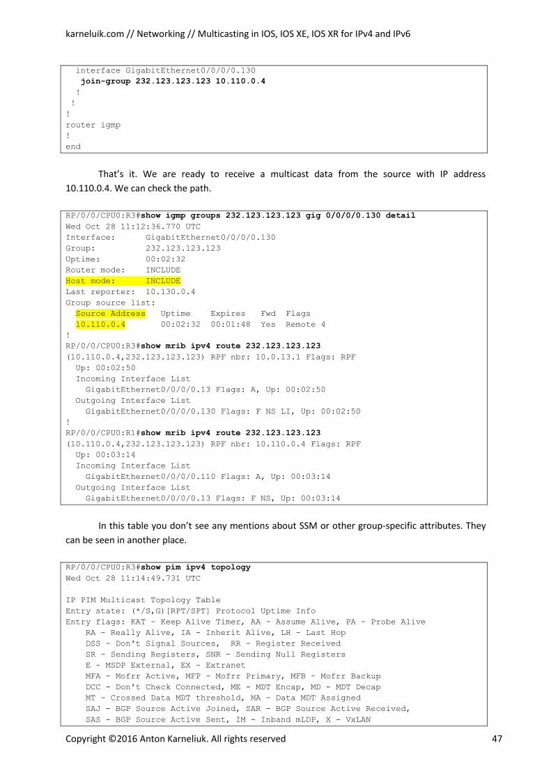
karneluik.com // Networking // Multicasting in IOS, IOS XE, IOS XR for IPv4 and IPv6
Copyright ©2016 Anton Karneliuk. All rights reserved 47
interface GigabitEthernet0/0/0/0.130
join-group 232.123.123.123 10.110.0.4
!
!
!
router igmp
!
end
That’s it. We are ready to receive a multicast data from the source with IP address
10.110.0.4. We can check the path.
RP/0/0/CPU0:R3#show igmp groups 232.123.123.123 gig 0/0/0/0.130 detail
Wed Oct 28 11:12:36.770 UTC
Interface: GigabitEthernet0/0/0/0.130
Group: 232.123.123.123
Uptime: 00:02:32
Router mode: INCLUDE
Host mode: INCLUDE
Last reporter: 10.130.0.4
Group source list:
Source Address Uptime Expires Fwd Flags
10.110.0.4 00:02:32 00:01:48 Yes Remote 4
!
RP/0/0/CPU0:R3#show mrib ipv4 route 232.123.123.123
(10.110.0.4,232.123.123.123) RPF nbr: 10.0.13.1 Flags: RPF
Up: 00:02:50
Incoming Interface List
GigabitEthernet0/0/0/0.13 Flags: A, Up: 00:02:50
Outgoing Interface List
GigabitEthernet0/0/0/0.130 Flags: F NS LI, Up: 00:02:50
!
RP/0/0/CPU0:R1#show mrib ipv4 route 232.123.123.123
(10.110.0.4,232.123.123.123) RPF nbr: 10.110.0.4 Flags: RPF
Up: 00:03:14
Incoming Interface List
GigabitEthernet0/0/0/0.110 Flags: A, Up: 00:03:14
Outgoing Interface List
GigabitEthernet0/0/0/0.13 Flags: F NS, Up: 00:03:14
In this table you don’t see any mentions about SSM or other group-specific attributes. They
can be seen in another place.
RP/0/0/CPU0:R3#show pim ipv4 topology
Wed Oct 28 11:14:49.731 UTC
IP PIM Multicast Topology Table
Entry state: (*/S,G)[RPT/SPT] Protocol Uptime Info
Entry flags: KAT - Keep Alive Timer, AA - Assume Alive, PA - Probe Alive
RA - Really Alive, IA - Inherit Alive, LH - Last Hop
DSS - Don't Signal Sources, RR - Register Received
SR - Sending Registers, SNR - Sending Null Registers
E - MSDP External, EX - Extranet
MFA - Mofrr Active, MFP - Mofrr Primary, MFB - Mofrr Backup
DCC - Don't Check Connected, ME - MDT Encap, MD - MDT Decap
MT - Crossed Data MDT threshold, MA - Data MDT Assigned
SAJ - BGP Source Active Joined, SAR - BGP Source Active Received,
SAS - BGP Source Active Sent, IM - Inband mLDP, X - VxLAN
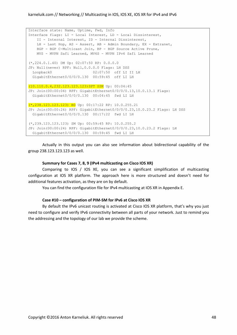
karneluik.com // Networking // Multicasting in IOS, IOS XE, IOS XR for IPv4 and IPv6
Copyright ©2016 Anton Karneliuk. All rights reserved 48
Interface state: Name, Uptime, Fwd, Info
Interface flags: LI - Local Interest, LD - Local Dissinterest,
II - Internal Interest, ID - Internal Dissinterest,
LH - Last Hop, AS - Assert, AB - Admin Boundary, EX - Extranet,
BGP - BGP C-Multicast Join, BP - BGP Source Active Prune,
MVS - MVPN Safi Learned, MV6S - MVPN IPv6 Safi Learned
(*,224.0.1.40) DM Up: 02:07:50 RP: 0.0.0.0
JP: Null(never) RPF: Null,0.0.0.0 Flags: LH DSS
Loopback0 02:07:50 off LI II LH
GigabitEthernet0/0/0/0.130 00:59:45 off LI LH
(10.110.0.4,232.123.123.123)SPT SSM Up: 00:04:45
JP: Join(00:00:04) RPF: GigabitEthernet0/0/0/0.13,10.0.13.1 Flags:
GigabitEthernet0/0/0/0.130 00:04:45 fwd LI LH
(*,238.123.123.123) BD Up: 00:17:22 RP: 10.0.255.21
JP: Join(00:00:24) RPF: GigabitEthernet0/0/0/0.23,10.0.23.2 Flags: LH DSS
GigabitEthernet0/0/0/0.130 00:17:22 fwd LI LH
(*,239.123.123.123) SM Up: 00:59:45 RP: 10.0.255.2
JP: Join(00:00:24) RPF: GigabitEthernet0/0/0/0.23,10.0.23.2 Flags: LH
GigabitEthernet0/0/0/0.130 00:59:45 fwd LI LH
Actually in this output you can also see information about bidirectional capability of the
group 238.123.123.123 as well.
Summary for Cases 7, 8, 9 (IPv4 multicasting on Cisco IOS XR)
Comparing to IOS / IOS XE, you can see a significant simplification of multicasting
configuration at IOS XR platform. The approach here is more structured and doesn’t need for
additional features activation, as they are on by default.
You can find the configuration file for IPv4 multicasting at IOS XR in Appendix E.
Case #10 – configuration of PIM-SM for IPv6 at Cisco IOS XR
By default the IPv6 unicast routing is activated at Cisco IOS XR platform, that’s why you just
need to configure and verify IPv6 connectivity between all parts of your network. Just to remind you
the addressing and the topology of our lab we provide the scheme.
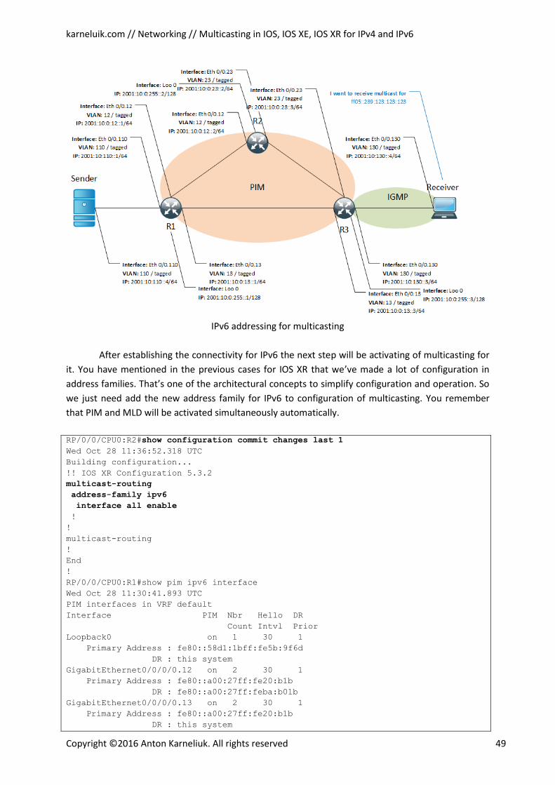
karneluik.com // Networking // Multicasting in IOS, IOS XE, IOS XR for IPv4 and IPv6
Copyright ©2016 Anton Karneliuk. All rights reserved 49
IPv6 addressing for multicasting
After establishing the connectivity for IPv6 the next step will be activating of multicasting for
it. You have mentioned in the previous cases for IOS XR that we’ve made a lot of configuration in
address families. That’s one of the architectural concepts to simplify configuration and operation. So
we just need add the new address family for IPv6 to configuration of multicasting. You remember
that PIM and MLD will be activated simultaneously automatically.
RP/0/0/CPU0:R2#show configuration commit changes last 1
Wed Oct 28 11:36:52.318 UTC
Building configuration...
!! IOS XR Configuration 5.3.2
multicast-routing
address-family ipv6
interface all enable
!
!
multicast-routing
!
End
!
RP/0/0/CPU0:R1#show pim ipv6 interface
Wed Oct 28 11:30:41.893 UTC
PIM interfaces in VRF default
Interface PIM Nbr Hello DR
Count Intvl Prior
Loopback0 on 1 30 1
Primary Address : fe80::58d1:1bff:fe5b:9f6d
DR : this system
GigabitEthernet0/0/0/0.12 on 2 30 1
Primary Address : fe80::a00:27ff:fe20:b1b
DR : fe80::a00:27ff:feba:b01b
GigabitEthernet0/0/0/0.13 on 2 30 1
Primary Address : fe80::a00:27ff:fe20:b1b
DR : this system
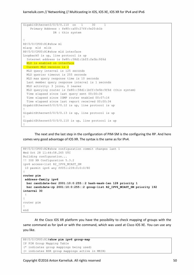
karneluik.com // Networking // Multicasting in IOS, IOS XE, IOS XR for IPv4 and IPv6
Copyright ©2016 Anton Karneliuk. All rights reserved 50
GigabitEthernet0/0/0/0.110 on 1 30 1
Primary Address : fe80::a00:27ff:fe20:b1b
DR : this system
!
RP/0/0/CPU0:R1#show ml
mlacp mld mlib
RP/0/0/CPU0:R1#show mld interface
Loopback0 is up, line protocol is up
Internet address is fe80::58d1:1bff:fe5b:9f6d
MLD is enabled on interface
Current MLD version is 2
MLD query interval is 125 seconds
MLD querier timeout is 255 seconds
MLD max query response time is 10 seconds
Last member query response interval is 1 seconds
MLD activity: 3 joins, 0 leaves
MLD querying router is fe80::58d1:1bff:fe5b:9f6d (this system)
Time elapsed since last query sent 00:00:36
Time elapsed since IGMP router enabled 00:07:16
Time elapsed since last report received 00:00:34
GigabitEthernet0/0/0/0.12 is up, line protocol is up
!
GigabitEthernet0/0/0/0.13 is up, line protocol is up
!
GigabitEthernet0/0/0/0.110 is up, line protocol is up
!
The next and the last step in the configuration of PIM-SM is the configuring the RP. And here
comes very good advantage of IOS XR. The syntax is the same as for IPv4.
RP/0/0/CPU0:R2#show configuration commit changes last 1
Wed Oct 28 11:44:58.265 UTC
Building configuration...
!! IOS XR Configuration 5.3.2
ipv6 access-list R2_IPV6_MCAST_SM
10 permit ipv6 any ff05::239:0:0:0/80
!
router pim
address-family ipv6
bsr candidate-bsr 2001:10:0:255::2 hash-mask-len 128 priority 1
bsr candidate-rp 2001:10:0:255::2 group-list R2_IPV6_MCAST_SM priority 192
interval 30
!
!
router pim
!
end
At the Cisco IOS XR platform you have the possibility to check mapping of groups with the
same command as for ipv4 or with the command, which was used at Cisco IOS XE. You can use any
you like.
RP/0/0/CPU0:R1#show pim ipv6 group-map
IP PIM Group Mapping Table
(* indicates group mappings being used)
(+ indicates BSR group mappings active in MRIB)
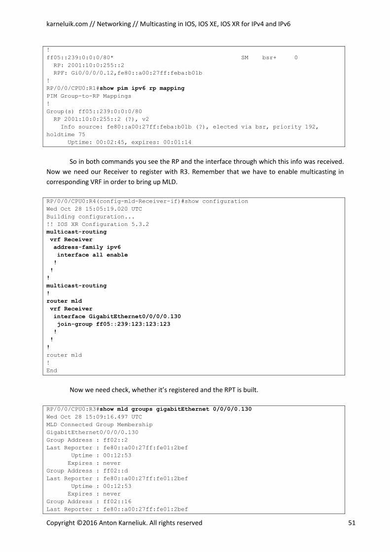
karneluik.com // Networking // Multicasting in IOS, IOS XE, IOS XR for IPv4 and IPv6
Copyright ©2016 Anton Karneliuk. All rights reserved 51
!
ff05::239:0:0:0/80* SM bsr+ 0
RP: 2001:10:0:255::2
RPF: Gi0/0/0/0.12,fe80::a00:27ff:feba:b01b
!
RP/0/0/CPU0:R1#show pim ipv6 rp mapping
PIM Group-to-RP Mappings
!
Group(s) ff05::239:0:0:0/80
RP 2001:10:0:255::2 (?), v2
Info source: fe80::a00:27ff:feba:b01b (?), elected via bsr, priority 192,
holdtime 75
Uptime: 00:02:45, expires: 00:01:14
So in both commands you see the RP and the interface through which this info was received.
Now we need our Receiver to register with R3. Remember that we have to enable multicasting in
corresponding VRF in order to bring up MLD.
RP/0/0/CPU0:R4(config-mld-Receiver-if)#show configuration
Wed Oct 28 15:05:19.020 UTC
Building configuration...
!! IOS XR Configuration 5.3.2
multicast-routing
vrf Receiver
address-family ipv6
interface all enable
!
!
!
multicast-routing
!
router mld
vrf Receiver
interface GigabitEthernet0/0/0/0.130
join-group ff05::239:123:123:123
!
!
!
router mld
!
End
Now we need check, whether it’s registered and the RPT is built.
RP/0/0/CPU0:R3#show mld groups gigabitEthernet 0/0/0/0.130
Wed Oct 28 15:09:16.497 UTC
MLD Connected Group Membership
GigabitEthernet0/0/0/0.130
Group Address : ff02::2
Last Reporter : fe80::a00:27ff:fe01:2bef
Uptime : 00:12:53
Expires : never
Group Address : ff02::d
Last Reporter : fe80::a00:27ff:fe01:2bef
Uptime : 00:12:53
Expires : never
Group Address : ff02::16
Last Reporter : fe80::a00:27ff:fe01:2bef
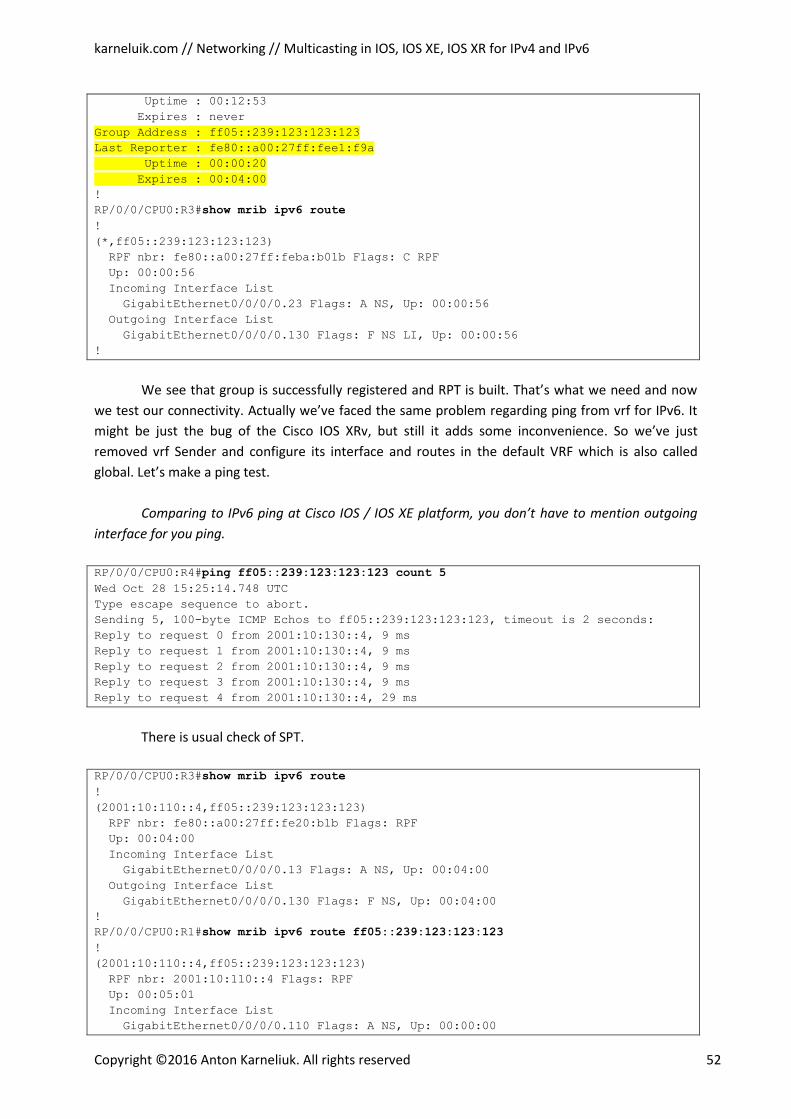
karneluik.com // Networking // Multicasting in IOS, IOS XE, IOS XR for IPv4 and IPv6
Copyright ©2016 Anton Karneliuk. All rights reserved 52
Uptime : 00:12:53
Expires : never
Group Address : ff05::239:123:123:123
Last Reporter : fe80::a00:27ff:fee1:f9a
Uptime : 00:00:20
Expires : 00:04:00
!
RP/0/0/CPU0:R3#show mrib ipv6 route
!
(*,ff05::239:123:123:123)
RPF nbr: fe80::a00:27ff:feba:b01b Flags: C RPF
Up: 00:00:56
Incoming Interface List
GigabitEthernet0/0/0/0.23 Flags: A NS, Up: 00:00:56
Outgoing Interface List
GigabitEthernet0/0/0/0.130 Flags: F NS LI, Up: 00:00:56
!
We see that group is successfully registered and RPT is built. That’s what we need and now
we test our connectivity. Actually we’ve faced the same problem regarding ping from vrf for IPv6. It
might be just the bug of the Cisco IOS XRv, but still it adds some inconvenience. So we’ve just
removed vrf Sender and configure its interface and routes in the default VRF which is also called
global. Let’s make a ping test.
Comparing to IPv6 ping at Cisco IOS / IOS XE platform, you don’t have to mention outgoing
interface for you ping.
RP/0/0/CPU0:R4#ping ff05::239:123:123:123 count 5
Wed Oct 28 15:25:14.748 UTC
Type escape sequence to abort.
Sending 5, 100-byte ICMP Echos to ff05::239:123:123:123, timeout is 2 seconds:
Reply to request 0 from 2001:10:130::4, 9 ms
Reply to request 1 from 2001:10:130::4, 9 ms
Reply to request 2 from 2001:10:130::4, 9 ms
Reply to request 3 from 2001:10:130::4, 9 ms
Reply to request 4 from 2001:10:130::4, 29 ms
There is usual check of SPT.
RP/0/0/CPU0:R3#show mrib ipv6 route
!
(2001:10:110::4,ff05::239:123:123:123)
RPF nbr: fe80::a00:27ff:fe20:b1b Flags: RPF
Up: 00:04:00
Incoming Interface List
GigabitEthernet0/0/0/0.13 Flags: A NS, Up: 00:04:00
Outgoing Interface List
GigabitEthernet0/0/0/0.130 Flags: F NS, Up: 00:04:00
!
RP/0/0/CPU0:R1#show mrib ipv6 route ff05::239:123:123:123
!
(2001:10:110::4,ff05::239:123:123:123)
RPF nbr: 2001:10:110::4 Flags: RPF
Up: 00:05:01
Incoming Interface List
GigabitEthernet0/0/0/0.110 Flags: A NS, Up: 00:00:00
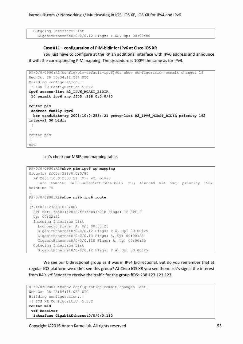
karneluik.com // Networking // Multicasting in IOS, IOS XE, IOS XR for IPv4 and IPv6
Copyright ©2016 Anton Karneliuk. All rights reserved 53
Outgoing Interface List
GigabitEthernet0/0/0/0.12 Flags: F NS, Up: 00:00:00
Case #11 – configuration of PIM-bidir for IPv6 at Cisco IOS XR
You just have to configure at the RP an additional interface with IPv6 address and announce
it with the corresponding PIM mapping. The procedure is 100% the same as for IPv4.
RP/0/0/CPU0:R2(config-pim-default-ipv6)#do show configuration commit changes l$
Wed Oct 28 15:34:12.564 UTC
Building configuration...
!! IOS XR Configuration 5.3.2
ipv6 access-list R2_IPV6_MCAST_BIDIR
10 permit ipv6 any ff05::238:0:0:0/80
!
router pim
address-family ipv6
bsr candidate-rp 2001:10:0:255::21 group-list R2_IPV6_MCAST_BIDIR priority 192
interval 30 bidir
!
!
router pim
!
end
Let’s check our MRIB and mapping table.
RP/0/0/CPU0:R1#show pim ipv6 rp mapping
Group(s) ff05::238:0:0:0/80
RP 2001:10:0:255::21 (?), v2, bidir
Info source: fe80::a00:27ff:feba:b01b (?), elected via bsr, priority 192,
holdtime 75
!
RP/0/0/CPU0:R1#show mrib ipv6 route
!
(*,ff05::238:0:0:0/80)
RPF nbr: fe80::a00:27ff:feba:b01b Flags: IF RPF P
Up: 00:32:31
Incoming Interface List
Loopback0 Flags: A, Up: 00:00:25
GigabitEthernet0/0/0/0.12 Flags: F A, Up: 00:00:25
GigabitEthernet0/0/0/0.13 Flags: A, Up: 00:00:25
GigabitEthernet0/0/0/0.110 Flags: A, Up: 00:00:25
Outgoing Interface List
GigabitEthernet0/0/0/0.12 Flags: F A, Up: 00:00:25
We see our bidirectional group as it was in IPv4 bidirectional. But do you remember that at
regular IOS platform we didn’t see this group? At Cisco IOS XR you see them. Let’s signal the interest
from R4’s vrf Sender to receive the traffic for the group ff05::238:123:123:123.
RP/0/0/CPU0:R4#show configuration commit changes last 1
Wed Oct 28 15:56:18.050 UTC
Building configuration...
!! IOS XR Configuration 5.3.2
router mld
vrf Receiver
interface GigabitEthernet0/0/0/0.130
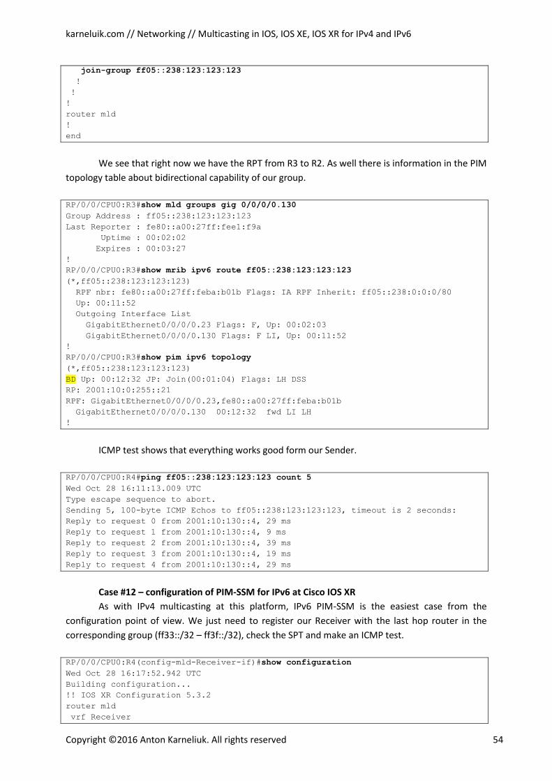
karneluik.com // Networking // Multicasting in IOS, IOS XE, IOS XR for IPv4 and IPv6
Copyright ©2016 Anton Karneliuk. All rights reserved 54
join-group ff05::238:123:123:123
!
!
!
router mld
!
end
We see that right now we have the RPT from R3 to R2. As well there is information in the PIM
topology table about bidirectional capability of our group.
RP/0/0/CPU0:R3#show mld groups gig 0/0/0/0.130
Group Address : ff05::238:123:123:123
Last Reporter : fe80::a00:27ff:fee1:f9a
Uptime : 00:02:02
Expires : 00:03:27
!
RP/0/0/CPU0:R3#show mrib ipv6 route ff05::238:123:123:123
(*,ff05::238:123:123:123)
RPF nbr: fe80::a00:27ff:feba:b01b Flags: IA RPF Inherit: ff05::238:0:0:0/80
Up: 00:11:52
Outgoing Interface List
GigabitEthernet0/0/0/0.23 Flags: F, Up: 00:02:03
GigabitEthernet0/0/0/0.130 Flags: F LI, Up: 00:11:52
!
RP/0/0/CPU0:R3#show pim ipv6 topology
(*,ff05::238:123:123:123)
BD Up: 00:12:32 JP: Join(00:01:04) Flags: LH DSS
RP: 2001:10:0:255::21
RPF: GigabitEthernet0/0/0/0.23,fe80::a00:27ff:feba:b01b
GigabitEthernet0/0/0/0.130 00:12:32 fwd LI LH
!
ICMP test shows that everything works good form our Sender.
RP/0/0/CPU0:R4#ping ff05::238:123:123:123 count 5
Wed Oct 28 16:11:13.009 UTC
Type escape sequence to abort.
Sending 5, 100-byte ICMP Echos to ff05::238:123:123:123, timeout is 2 seconds:
Reply to request 0 from 2001:10:130::4, 29 ms
Reply to request 1 from 2001:10:130::4, 9 ms
Reply to request 2 from 2001:10:130::4, 39 ms
Reply to request 3 from 2001:10:130::4, 19 ms
Reply to request 4 from 2001:10:130::4, 29 ms
Case #12 – configuration of PIM-SSM for IPv6 at Cisco IOS XR
As with IPv4 multicasting at this platform, IPv6 PIM-SSM is the easiest case from the
configuration point of view. We just need to register our Receiver with the last hop router in the
corresponding group (ff33::/32 – ff3f::/32), check the SPT and make an ICMP test.
RP/0/0/CPU0:R4(config-mld-Receiver-if)#show configuration
Wed Oct 28 16:17:52.942 UTC
Building configuration...
!! IOS XR Configuration 5.3.2
router mld
vrf Receiver
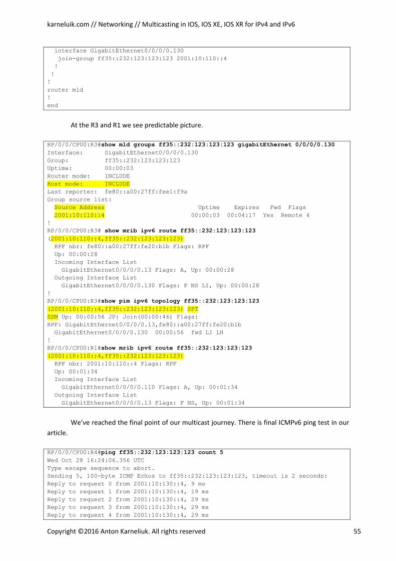
karneluik.com // Networking // Multicasting in IOS, IOS XE, IOS XR for IPv4 and IPv6
Copyright ©2016 Anton Karneliuk. All rights reserved 55
interface GigabitEthernet0/0/0/0.130
join-group ff35::232:123:123:123 2001:10:110::4
!
!
!
router mld
!
end
At the R3 and R1 we see predictable picture.
RP/0/0/CPU0:R3#show mld groups ff35::232:123:123:123 gigabitEthernet 0/0/0/0.130
Interface: GigabitEthernet0/0/0/0.130
Group: ff35::232:123:123:123
Uptime: 00:00:03
Router mode: INCLUDE
Host mode: INCLUDE
Last reporter: fe80::a00:27ff:fee1:f9a
Group source list:
Source Address Uptime Expires Fwd Flags
2001:10:110::4 00:00:03 00:04:17 Yes Remote 4
!
RP/0/0/CPU0:R3# show mrib ipv6 route ff35::232:123:123:123
(2001:10:110::4,ff35::232:123:123:123)
RPF nbr: fe80::a00:27ff:fe20:b1b Flags: RPF
Up: 00:00:28
Incoming Interface List
GigabitEthernet0/0/0/0.13 Flags: A, Up: 00:00:28
Outgoing Interface List
GigabitEthernet0/0/0/0.130 Flags: F NS LI, Up: 00:00:28
!
RP/0/0/CPU0:R3#show pim ipv6 topology ff35::232:123:123:123
(2001:10:110::4,ff35::232:123:123:123) SPT
SSM Up: 00:00:56 JP: Join(00:00:46) Flags:
RPF: GigabitEthernet0/0/0/0.13,fe80::a00:27ff:fe20:b1b
GigabitEthernet0/0/0/0.130 00:00:56 fwd LI LH
!
RP/0/0/CPU0:R1#show mrib ipv6 route ff35::232:123:123:123
(2001:10:110::4,ff35::232:123:123:123)
RPF nbr: 2001:10:110::4 Flags: RPF
Up: 00:01:34
Incoming Interface List
GigabitEthernet0/0/0/0.110 Flags: A, Up: 00:01:34
Outgoing Interface List
GigabitEthernet0/0/0/0.13 Flags: F NS, Up: 00:01:34
We’ve reached the final point of our multicast journey. There is final ICMPv6 ping test in our
article.
RP/0/0/CPU0:R4#ping ff35::232:123:123:123 count 5
Wed Oct 28 16:24:06.356 UTC
Type escape sequence to abort.
Sending 5, 100-byte ICMP Echos to ff35::232:123:123:123, timeout is 2 seconds:
Reply to request 0 from 2001:10:130::4, 9 ms
Reply to request 1 from 2001:10:130::4, 19 ms
Reply to request 2 from 2001:10:130::4, 29 ms
Reply to request 3 from 2001:10:130::4, 29 ms
Reply to request 4 from 2001:10:130::4, 29 ms
karneluik.com // Networking // Multicasting in IOS, IOS XE, IOS XR for IPv4 and IPv6
Copyright ©2016 Anton Karneliuk. All rights reserved 56
Hurray! Everything works well in our network. You can look into configuration for IOS XR that
covers both IPv4 and IPv6 multicasting at the Appendix F.
Summary
In this article we’ve described the operation of multicasting. Starting with the theory and
ending with configuration and verification we’ve covered almost all the cases which you can meet.
We’ve described the BSR as a main mechanism for distribution information about the RP and its
mapping due to its vendor neutrality. It’s a standard, that’s why you can implement this solution in
multivendor network. As well we provide the same level in-depth overview of IPv6 multicasting as
nowadays we are in the process of the shift to this technology. We can outline different approach for
configuration that Cisco IOS XR platform has. It’s easier to configure multicasting both for IPv4 and
IPv6 there due to same commands and common framework. On the other hand we can see many
differences between configurations of multicasting at Cisco IOS / IOS XE platform. It seems that such
differences have historical roots and shows the development of regular IOS in progress as IPv4 was
introduced much earlier than IPv6.
Multicasting is very important and interesting technology which penetration in data
transmission will grow with development of IoT and collaborative technologies. I hope that now you
understand it better. Thanks for your time and I’ll be appreciate to hear feedback from you.
Anton Karneliuk
CCIE RS #49412, MSc.
@AntonKarneliuk

karneluik.com // Networking // Multicasting in IOS, IOS XE, IOS XR for IPv4 and IPv6
Copyright ©2016 Anton Karneliuk. All rights reserved 57
References:
[a] RFC 5771: IANA Guidelines for IPv4 Multicast Address Assignments.
https://tools.ietf.org/html/rfc5771
[b] RFC 4291: IP Version 6 Addressing Architecture. https://tools.ietf.org/html/rfc4291
[c] RFC 3376: Internet Group Management Protocol, Version 3.
https://tools.ietf.org/html/rfc3376
[d] RFC 2710: Multicast Listener Discovery (MLD) for IPv6. https://tools.ietf.org/html/rfc2710
[e] Cisco Command Reference Guide:
[e.1] For IOS: http://www.cisco.com/c/en/us/support/ios-nx-os-software/ios-15-5m-
t/products-command-reference-list.html
[e.2] For IOS XE: http://www.cisco.com/c/en/us/support/ios-nx-os-software/ios-xe-3-
15s/model.html#CommandReferences
[e.3] For IOS XR: http://www.cisco.com/c/en/us/support/ios-nx-os-software/ios-xr-
software/products-command-reference-list.html
[f] RFC xxx: Embedded RP for IPv6
[g] Routing TCP/IP, Volume II (CCIE Professional Development) by Jeff Doyle CCIE #1919,
Jennifer DeHaven Carroll CCIE #1402, ISBN : 1-57870-089-2
[h]
http://www.cisco.com/en/US/docs/ios_xr_sw/ios_xrv/install_config/b_xrvr_432_chapter_010.html
[i] http://www.cisco.com/c/en/us/products/collateral/routers/cloud-services-router-1000v-
series/datasheet-c78-732157.html
[j] http://www.cisco.com/c/en/us/products/collateral/routers/cloud-services-router-1000v-
series/datasheet-c78-733443.html
Recommended