NEP Therm Heater Installation instructions
NEP_Therm-120221.doc 1
READ AND SAVE THESE INSTALLATION INSTRUCTIONS
Technical data Model C Open Coil Elements
Maximum Inlet air temperature 95˚F (35˚C) Maximum outlet air temperature 200˚F (93˚C)
Minimum distance from obstacle or obstruction in duct 36’’ (915mm) upstream and downstream of electric heater
Inlet bushing 2 knock out 7/8’’ (22.2mm) or 1 ⅜’’ (34.9mm)
Control signal Modulating See Electric diagram
Air flow direction Horizontal or Vertical Voltage
See the name plate Current
Power Control voltage
Minimum air velocity Ensure minimum air flow – as marked on name plate. Insufficient airflow will lead to opening of automatic thermal cut-out. This may damage heating elements and controls.
! Caution, for safety reason, modification or alteration to internal electric connection or component of theNEP Them is strictly forbidden. Any non-authorized modification will void the warranty.
Dimensions
B
A W
C D
1"(25.4 mm)2"
(51 mm)
2"(51 mm) 1"
(25.4 mm)
Dimension Inches Metric (mm)
A 4.09 103.9
B 5" ø 8.78 223.1 6" ø 8" ø 10.78 273.9
C 7.22 183.5 D 9.08 230.8
W 5" ø 6.12 155.5 6" ø 7.12 180.9 8" ø 9.12 231.7
Nomenclature: D F Z00RC
0 : No screen on left side of the heater1 : Screen on left side of the heater0 : No screen on right side of the heater1 : Screen on right side of the heater
16
10: 1 Kw15: 1.5 Kw
-
8: Ø 8'’ collar
0
40 : 4 Kw50: 5 Kw
20: 2 Kw30: 3 Kw
-
T: Toggle switch
A: 120 VacB: 208 VacC: 240 Vac
R : Room thermostat (STS3-13)D : Internal set point with duct sensor (STC8-13)S : Remote set point (ITO3) with duct sensor (STC8-13)N : Controls by others
T RA
05: 0.5 Kw
6: Ø 6'’ collar5: Ø 5'’ collar
Features: Zero clearance construction Horizontal or Vertical airflow, any direction accepted Fully proportional electric heater. Neptronic HEC patented universal controller. 4 different thermostats configuration options available.
NEP Therm Heater Installation instructions
2
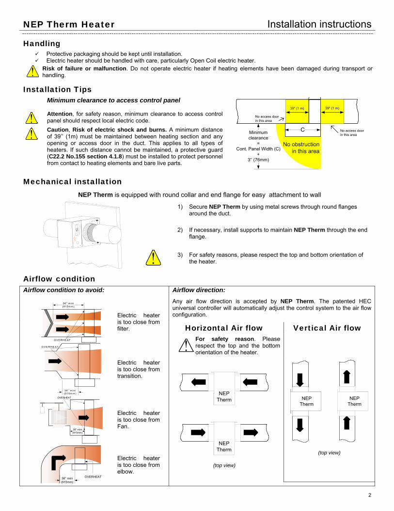
Handling Protective packaging should be kept until installation. Electric heater should be handled with care, particularly Open Coil electric heater.
! Risk of failure or malfunction. Do not operate electric heater if heating elements have been damaged during transport or handling.
Installation Tips Minimum clearance to access control panel
Minimumclearance
=Cont. Panel Width (C)
+3'’ (76mm)
No obstructionin this area
C
39" (1 m) 39" (1 m)
No access door in this area
No access door in this area
! Attention, for safety reason, minimum clearance to access control panel should respect local electric code.
!
Caution, Risk of electric shock and burns. A minimum distance of 39’’ (1m) must be maintained between heating section and any opening or access door in the duct. This applies to all types of heaters. If such distance cannot be maintained, a protective guard (C22.2 No.155 section 4.1.8) must be installed to protect personnel from contact to heating elements and bare live parts.
Mechanical installation NEP Therm is equipped with round collar and end flange for easy attachment to wall
1) Secure NEP Therm by using metal screws through round flanges around the duct.
2) If necessary, install supports to maintain NEP Therm through the end flange.
! 3) For safety reasons, please respect the top and bottom orientation of the heater.
Airflow condition Airflow condition to avoid:
36'’ m ini(915m m )
OVERHEAT
Electric heater is too close from filter.
3 6 '’ m in i(9 1 5 m m )
O V E R H E A T
Electric heater is too close from transition.
36'’ mini(915mm)
OVERHEAT
Electric heater is too close from Fan.
36'’ mini(915mm)
OVERHEAT
Electric heater is too close from elbow.
Airflow direction: Any air flow direction is accepted by NEP Therm. The patented HEC universal controller will automatically adjust the control system to the air flow configuration.
Horizontal Air flow Vertical Air flow
!For safety reason. Please respect the top and the bottom orientation of the heater.
NEPTherm
NEPTherm
(top view)
NEPTherm
NEPTherm
(top view)
NEP Therm Heater Installation instructions
3
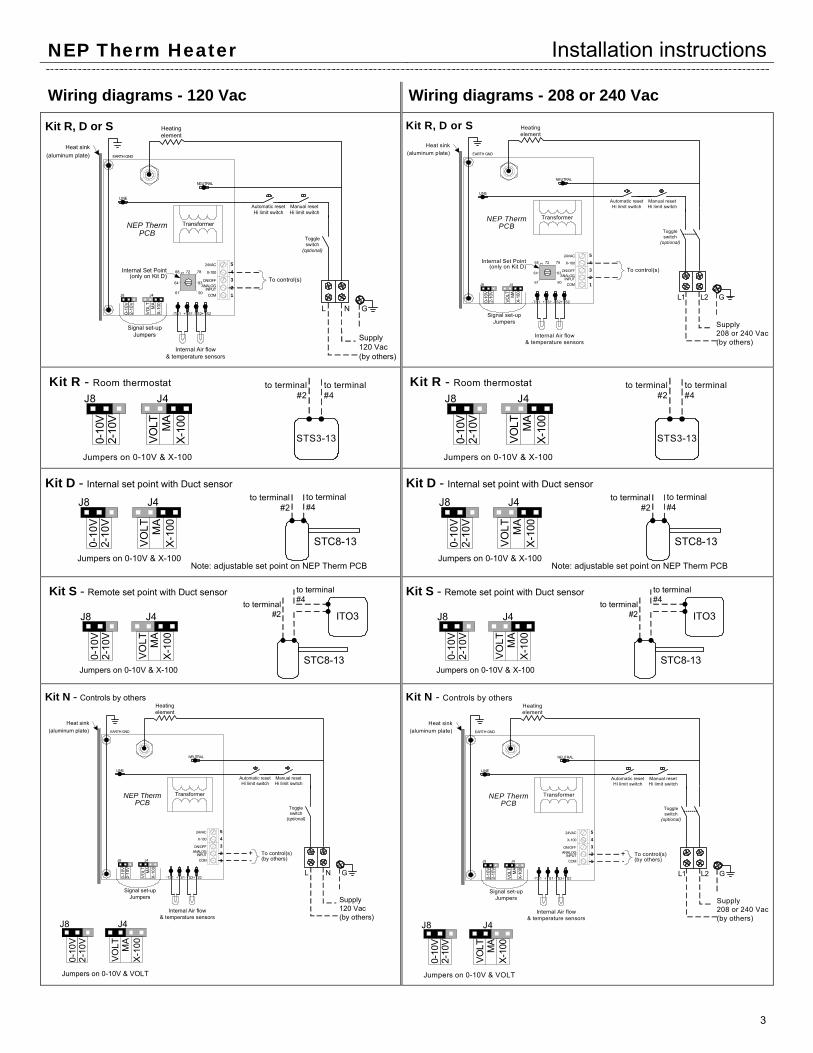
Wiring diagrams - 120 Vac Wiring diagrams - 208 or 240 Vac
Kit R, D or SHeat sink
(aluminum plate)
Transformer
-TS1 +TS2-TS2+TS1
COM
NEUTRAL
EARTH GND
LINE
Manual resetHi limit switch
Toggleswitch
(optional)
Automatic resetHi limit switch
L N
Internal Air flow& temperature sensors
G
Supply120 Vac(by others)
Signal set-upJumpers
NEP ThermPCB
Internal Set Point(only on Kit D)
61
83
68 72 78
90
64
P1
Heatingelement
J8 J4
X-1
00MA
VO
LT
0-10
V2-
10V
54321
ANALOGINPUT
ON/OFF
X-100
24VAC
To control(s)
Kit R, D or SHeat sink
(aluminum plate)
Transformer
-TS1 +TS2-TS2+TS1
COM
NEUTRAL
EARTH GND
LINE
Manual resetHi limit switch
Toggleswitch
(optional)
Automatic resetHi limit switch
L1 L2
Internal Air flow& temperature sensors
G
Supply208 or 240 Vac(by others)
Signal set-upJumpers
NEP ThermPCB
Internal Set Point(only on Kit D)
61
83
68 72 78
90
64
P1
Heatingelement
J8 J4
X-10
0M
AVO
LT
0-10
V2-
10V
54321
ANALOGINPUT
ON/OFF
X-100
24VAC
To control(s)
STS3-13
Jumpers on 0-10V & X-100
to terminal#2
to terminal#4
Kit R - Room thermostat
J8 J4
X-10
0M
AVO
LT
0-10
V2-
10V
STS3-13
Jumpers on 0-10V & X-100
to terminal#2
to terminal#4
Kit R - Room thermostat
J8 J4
X-10
0M
AVO
LT
0-10
V2-
10V
STC8-13Jumpers on 0-10V & X-100
to terminal #2
to terminal #4
Kit D - Internal set point with Duct sensor
Note: adjustable set point on NEP Therm PCB
J8 J4
X-10
0M
AVO
LT
0-10
V2-
10V
STC8-13Jumpers on 0-10V & X-100
to terminal #2
to terminal #4
Kit D - Internal set point with Duct sensor
Note: adjustable set point on NEP Therm PCB
J8 J4
X-10
0M
AVO
LT
0-10
V2-
10V
ITO3
STC8-13Jumpers on 0-10V & X-100
to terminal #2
to terminal #4
Kit S - Remote set point with Duct sensor
J8 J4
X-1
00MA
VO
LT
0-10
V2-
10V
ITO3
STC8-13Jumpers on 0-10V & X-100
to terminal #2
to terminal #4
Kit S - Remote set point with Duct sensor
J8 J4
X-1
00MA
VO
LT
0-10
V2-
10V
Kit N - Controls by others
Jumpers on 0-10V & VOLT
Heat sink(aluminum plate)
Transformer
-TS1 +TS2-TS2+TS1
COM
NEUTRAL
EARTH GND
LINE
Manual resetHi limit switch
Toggleswitch
(optional)
Automatic resetHi limit switch
L N
Internal Air flow& temperature sensors
G
Supply120 Vac(by others)
Signal set-upJumpers
NEP ThermPCB
Heatingelement
54321
ANALOGINPUT
ON/OFF
X-100
24VAC
J8
0-10
V2-
10V
J4
X-1
00MA
VOLT
To control(s)(by others)J8
0-10
V2-
10V
J4
X-1
00MA
VOLT
+-
Kit N - Controls by others
Jumpers on 0-10V & VOLT
Heat sink(aluminum plate)
Transformer
-TS1 +TS2-TS2+TS1
COM
NEUTRAL
EARTH GND
LINE
Manual resetHi limit switch
Toggleswitch
(optional)
Automatic resetHi limit switch
L1 L2
Internal Air flow& temperature sensors
G
Supply208 or 240 Vac(by others)
Signal set-upJumpers
NEP ThermPCB
Heatingelement
54321
ANALOGINPUT
ON/OFF
X-100
24VAC
J8
0-10
V2-
10V
J4
X-10
0M
AVO
LT
To control(s)(by others)J8
0-10
V2-
10V
J4
X-10
0M
AVO
LT
+-
NEP Therm Heater Installation instructions
4
Controls signal & Wirings See enclosed Wiring diagrams
Electric Installation See enclosed Wiring diagrams
DANGER: Risk of electric shock. Disconnect all supplies before working on any circuit. CAUTION: Risk of malfunction. Use only copper wires suitable for 105˚C (221˚F). CAUTION: Electric installation should conform to local electrical code. CAUTION: If a disconnect switch and/or fuses have not been supplied on control panel of electric heater, disconnect
switch and/or fuses should be installed on supply. CAUTION: Gauge of electric supply wires should be of appropriate section, function of line current, as per local
electrical code. See the name plate for information on voltage and current.
Connect all wires to appropriate terminals as per electrical diagram affixed inside the control panel door. Correct connection tightening should be verified before start up, and after short period of operation (typically after 2 weeks).
Operation condition Air Flow :
Air flow should not be lower than the minimum air flow indicated on name plate. Air flow going through the electric heater should be free of combustible particle, flammable vapour or gas. Open Coil: Air flow going through the electric heater should be free of dust.
Zero clearance construction:
NEP Therm are designed and approved for zero clearance to combustible material. Insulation material may be installed directly onto electric heater surfaces or onto air duct. However control panel should be accessible for maintenance.
!
Risk of failure or malfunction. Do not cover aluminium side plate of heater with insulation material.
Maintenance NEP Therm does not require specific maintenance; however we recommend a yearly inspection.
1) Visual inspection
Risk of electric shock. Disconnect all supplies before any visual inspection.
Verify good condition of heating element. Open Coil: Verify carefully that there is no dust accumulation. Verify any indication of overheating condition as well as any trace of oxidation.
2) Electrical inspection
Risk of electric shock. Disconnect all supplies before any electrical inspection.
Verify correct of electrical connection tightening. Verify the good condition of fuses (if any). Verify resistance of each circuit against ground. Verify correct operation of contactor(s).
If necessary, electrical component should be replaced only with identical origin component.
Technical support For any question or specific request please consult our web site:
www.neptronic.com Or call:
1 800 361-2308. Ask for the electric heater department.
or (514) 333-1433 Fax : (514) 333-3163
Recommended