Service Source
K
Network Server 500 and700 Series
Network Server 500/132, Network Server 700/150,and Network Server 700/200

Service Source
K
Basics
Network Server 500 and700 Series

Basics Overview - 1
Overview
The Network Server 500 Series and Network Server 700 Series are a family of high-performance servers based on the PowerPC 604 or 604e Reduced Instruction Set Computer (RISC) microprocessor. Designed around an innovative architecture, the servers provide high performance and scalability for medium to large workgroups running AIX-based applications.

Basics Overview - 2
Network Server 500 Series Features
Features of the Network Server 500 Series include the following:• 132-MHz PowerPC 604 microprocessor• 32K on-chip cache• 512K Level 2 cache• 32 MB main DRAM memory, expandable to 512 MB• Six PCI expansion slots• Seven drive bays for internal, redundant drives that are
hot-swappable with RAID• Total disk capacity with RAID: 368 GB• Built-in Ethernet interface using the Apple Ethernet
Cable System (AAUI)• One SCSI-1 channel with external port• Two Fast/Wide SCSI-2 channels for internal devices

Basics Overview - 3
• Built-in 1024 x 768, 800 x 600, 640 x 480 video support for 14-inch, 15-inch, 17-inch, and 20-inch multi-sync monitors
• CD, floppy bays (DAT is optional)• An LCD display that monitors server activity and can be
used for diagnostic tests
Network Server 700 Series Features
Features of the Network Server 700 Series include the following:• 150-MHz PowerPC 604 microprocessor (Network
Server 700/150) or 200-MHz PowerPC 604e microprocessor (Network Server 700/200) or two 200-MHz PowerPC 604e microprocessors (Network Server 700/200SMP)
• 32K on-chip cache (Network Server 700/150) or 64K on-chip cache (Network Server 700/200)

Basics Overview - 4
• 1 MB Level 2 cache• 48 MB main DRAM memory, expandable to 512 MB• Six PCI expansion slots• Seven drive bays in the front for internal, redundant
drives that are hot-swappable with RAID• Two drive bays in the rear for internal fixed drives• Total disk capacity with RAID: 368 GB• Built-in Ethernet interface using the Apple Ethernet
Cable System (AAUI)• One SCSI-1 channel with external port• Two Fast/Wide SCSI-2 channels for internal devices• Redundant, hot-swappable power supplies• Built-in 1024 x 768, 800 x 600, 640 x 480 video
support for 14-inch, 15-inch, 17-inch, and 20-inch multi-sync monitors
• CD, floppy bays (DAT or 8 mm tape drive is optional)• An LCD display that monitors server activity and can be
used for diagnostic tests

Basics Configurations - 5
Configurations
At product introduction, the following was the standard configuration for the Network Server 500/132:• 132-MHz PowerPC 604 processor card• 512 KB Level 2 cache• 32 MB parity DRAM minimum• 2 GB Fast/Wide hard drive• DAT2 tape drive• AppleCD 600i CD-ROM drive• Floppy disk drive• AppleTalk administration utilities• 325 watt power supply
At product introduction, the standard configuration for the Network Server 700/150 was• 150-MHz PowerPC 604 processor card• 1 MB Level 2 cache

Basics Configurations - 6
• 48 MB parity DRAM minimum• 4 GB Fast/Wide hard drive• DAT2 tape drive• AppleCD 600i CD-ROM drive• Floppy disk drive• AppleTalk administration utilities• 425 watt power supply
At product introduction, the standard configuration for the Network Server 700/200 was• 200-MHz PowerPC 604e processor card• 1 MB Level 2 cache• 48 MB parity DRAM minimum• Two 4 GB Fast/Wide hard drives• AppleCD 1200i CD-ROM drive• Floppy disk drive• AppleTalk administration utilities• 425 watt power supply

Basics Configurations - 7
Note:
AIX software does not come preinstalled in standard configurations of the Network Server 500 and 700 Series. The AIX software must be purchased separately.

Basics Options and Upgrades - 8
Options and Upgrades
Apple offers the following options and upgrades to enhance the operation and performance of the Network Server 500 and 700 Series.
• Processor Upgrade
Card with One 200-MHz 604e PowerPC ProcessorM5177Z/A
• Main Memory
16 MB Parity Memory Kit M4017Z/A32 MB Parity Memory Kit M4018Z/A64 MB Parity Memory Kit M4019Z/A

Basics Options and Upgrades - 9
• Hard Drives
2 GB Fast/Wide SCSI Hard Drive w/ Tray M4022Z/A4 GB Fast/Wide SCSI Hard Drive w/ Tray M4023Z/A9 GB Fast/Wide SCSI Hard Drive w/ Tray M5178Z/A
• Rear Hard Drives and Bracket
2 GB Fast/Wide SCSI Hard Drive & Bracket M4818Z/ATwo 4 GB Fast/Wide SCSI Hard Drives & Bracket M4819Z/A
• CD-ROM and Tape Drives
4-X CD-ROM Drive w/ Tray M4024Z/ADAT-2 SCSI Tape Drive w/ Tray M4025Z/A8 mm Tape Drive (20/40 GB) w/ Tray M4026Z/A

Basics Options and Upgrades - 10
• Storage Bay Accessories
SCSI Drive Adapter Kit (68 and 50-Pin) M4028Z/ASCSI Front Drive Bezel Kit M4029Z/A
• Redundant Power Supply (NS 700 Series Only)
425 W Hot-swappable Power Supply M4035Z/A
• PCI Expansion Cards
PCI RAID Disk Array Card M4030Z/ARAID External SCSI Cable (68-Pin to 68-Pin) M4031Z/APCI Fast Ethernet Card (100Base-TX) M3906Z/APCI Ethernet Card (10Base2/10Base-T/AAUI) M4709Z/A
• 19-inch Rack Mount Accessory Kit M4036Z/A

Basics Options and Upgrades - 11
• AIX Accessory Kit
AIX Accessory Kit, Version 4.1.4 M4525Z/AAIX Accessory Kit, Version 4.1.4.1 M4525Z/BAIX Accessory Kit, Version 4.1.5 M4525Z/CAIX Update Kit, Version 4.1.4 to Version 4.1.4.1 M5494Z/AAIX Upgrade Kit, Unlimited User M4891Z/A
Note:
Third-party manufacturers also offer a wide variety of products that can be installed to enhance the server.
Basics Service Strategy - 12
Service Strategy
Service the Network Server 500 and 700 Series through module exchange and parts replacement. Customers can request on-site service from an Apple Authorized Service Provider Plus (AASP+) or carry-in service from an AASP, or they can choose service from the Apple Assurance program.
Ordering
Apple service providers planning to support the Network Server 500 and 700 Series may purchase Service modules and parts to develop servicing capability. To order parts, use the AppleOrder system or refer to the “Service Price Pages.”
Large businesses, universities, and K-12 accounts must
Basics Service Strategy - 13
provide a purchase order on all transactions, including orders placed through the AppleOrder system. Service providers not enrolled in AppleOrder may fax their orders to Service Provider Support (512-908-8125) or mail them to
Apple Computer, Inc.Service Provider SupportMS 212-SPSAustin, TX 78714-9125
If you have further questions, please call Service Provider Support at 800-919-2775 and select option #1.

Basics Service Strategy - 14
Warranty and AppleCare
Both the Network Server 500 Series and Network Server 700 Series are covered under the Apple One-Year Limited Warranty. The AppleCare
Service Plan is also available for these systems. For part number and pricing information, refer to the AppleCare CPU “Service Price Pages.” Service providers are reimbursed for warranty and AppleCare repairs made to these systems.
Diagnostics
Use the Network Server Diagnostic Utility on the Service Source companion disc (or on its own floppy disk) to test the new servers. Refer to the Troubleshooting chapter for more information on the Network Server Diagnostic Utility.
Basics Safety Issues - 15
Safety Issues
See Bulletins/Safety for general safety information.
Skills and Tools
Knowledge of the AIX operating system and RAID technology is helpful. Familiarity with the Network Server Diagnostics Utility is a plus.
No additional tools are required for the Network Server 500 and 700 Series above and beyond what the service technician already has.

Basics Compatibility Issues - 16
Compatibility Issues
The following are compatibility issues associated with upgrading memory or installing PCI expansion cards for video, graphics applications, and networking and communications:• The Network Server uses 72-bit-wide, 168-pin parity
DRAM Dual Inline Memory Modules (DIMMs), which should be installed in matched pairs (for example, two 8 MB DIMMs). Your server’s DIMMs are fast-paged mode, parity DRAM, with an access time of 60-nanoseconds or faster. Nonparity DIMMs with 70-nanosecond or faster access time DRAM will work; however, if there is any nonparity DRAM installed, all server parity checking is disabled.

Basics Compatibility Issues - 17
• Some DIMMs and all Single Inline Memory Modules (SIMMs) from older Macintosh computers are not compatible. For more detailed information, see “Appendix B: DRAM Configurations” of “Setting up the Network Server.”
• The Network Server uses cards designed according to the Peripheral Component Interconnect (PCI) standard. Your server cannot accommodate NuBus cards, which were designed for older Macintosh computers.
• The combined power consumption of PCI expansion cards must not exceed the limits specified for the Network Server 500 and 700 Series.
• The Network Servers support only multisynchronous displays.
• The 8 mm tape drive can read from but not write to standard metal particle tapes. The tape heads must be cleaned after reading from a standard metal particle tape before an AME tape can be used.

Basics Setup and Operation - 18
Setup and Operation
Refer to “Chapter 5: Starting Up Your Server” of “Setting up the Network Server” and “Chapter 3: System Startup, Logging In, Shutting Down, and Rebooting” of “Using AIX, AppleTalk Services and Macintosh OS Utilities on the Network Server” for information on how to • Install AIX on the server• Start up, log in, shut down, and restart the server• Use AIX Windows and the Common Desktop Environment• Use InfoExplorer• Use system administration tools• Set up AppleTalk and AppleTalk Services• Use Disk Management Utility• Access the server remotely with CommandShell
Note:
You can find these manuals on the Service Source Companion CD.

Basics Setup and Operation - 19
Turning the Server On
To turn on the server you must perform the following steps:• Turn on the monitor.• Turn on all the external devices.• Turn the key in the rear drawer lock to the locked
position.• Turn the front lock key to the unlocked or locked position.• Turn the server on by pressing the Power On button
(next to the floppy drive).
The server will run the power-on self test and then clear the LCD display and display the ROM version and power supply status. During the startup process, messages will appear on the third line of the LCD display. Under normal circumstances, these messages will clear quickly, but if there is a startup problem, one of the messages may be displayed continuously.
Basics Setup and Operation - 20
Shutting Down the Server
Note:
You must have root privileges to shut down the server.
To shut down the server always use the Shutdown command as it is the safest and most thorough way to halt the server. Log in to the server as root and enter
shutdown -F
You can notify the users that the system is about to stop operations, terminate all existing processes, and unmount all filesystems by using the appropriate options provided in the Shutdown command. By default, the system waits one minute before stopping the user processes and the init process.

Basics Setup and Operation - 21
Restarting the Server
You must have root privileges to restart the server. Use the command
shutdown -r
instead of the Reboot command when the system is running and other users are logged in.

Basics Front View - 22
Front View
The following figure illustrates the front view of the Network Server 500 and 700 Series. Note that the monitor and keyboard must be purchased separately.

Basics Front View - 23
Figure: Network Server 500 and 700 Series Front View
Interrupt button
Front key switchlocks sliding securitydoor and base cover
Reset button
LCD displays systemdiagnostics and
status messages
Floppy disk drive
CD-ROM drive
Power button
Front internaldrive bays
Release buttons toremove base cover
Speaker
Optional tapedrive
Sliding securitydoor
Power suppliesNS500 Series includes asingle power supplyNS700 Series offers anoptional secondpower supply
Basics Back View - 24
Back View
The Network Server 500 Series and Network Server 700 Series offer the following external ports: SCSI, AAUI Ethernet, serial printer, serial modem, Apple Desktop Bus (ADB), sound input, and sound output.
The figures on the next pages illustrate the rear panel of the Network Server 500 and 700 Series.

Basics Back View - 25
Figure: Network Server 500 and 700 Series Back View
Optional rear bracket-mounted drives
(NS700 Series only)
Replaceable, hot-swappable fans
Power cordprotector
PCI cardconnection ports
Thumbscrews
Thumbscrews
Security lock
Hot-swappablefans
Rear drawer lock

Basics Back View - 26
Figure: Network Server 500 and 700 Series Ports
Sound output port
Serial connection ports
Sound input port
Monitor portVGA HD-IS videoconnects your monitor toyour server
Ethernet port
Status light
SCSI port
ADB port

Basics Logic Board - 27
Logic Board
The following figure illustrates the connectors, battery holder, cache and DRAM DIMM sockets, PCI slots, processor card slot, Cuda reset button, and the power on/off button on the Network Server 500 and 700 Series logic board.

Basics Logic Board - 28
Figure: Network Server 500 and 700 Series Logic Board Connectors
ROM SIMM
Cache DIMM
DRAM DIMM Slots
BatteryHolder
Audio OutputMicrophoneADBSerial Ports
VideoAAUI Ethernet
External SCSI-1Power on & Activity LED
FanKey
PCI Slots
Control BusSCSI Bus 0
SCSI Bus 1
Power Supply
Processor Card Slot
Cuda Reset Button
ROM SIMM
Cache DIMM
DRAM DIMM Slots
BatteryHolder
Audio OutputMicrophoneADBSerial Ports
VideoAAUI Ethernet
External SCSI-1Power on & Activity LED
FanKey
PCI Slots
Control BusSCSI Bus 0
SCSI Bus 1
Power Supply
Processor Card Slot
Cuda Reset Button

Basics Overview of Core Technologies - 29
Overview of Core Technologies
This section provides information on core technologies built into the Network Server 500 and 700 Series.
PowerPC 604 and 604e Microprocessor
The Network Server 500 Series and Network Server 700 Series are powered by a PowerPC 604 or 604e microprocessor. An implementation of the PowerPC family of RISC microprocessors, the PowerPC 604 or 604e uses RISC technology to deliver high performance at the lowest possible cost. Features include the following:• Full RISC processing architecture• 64-bit external data bus and a 32-bit address bus

Basics Overview of Core Technologies - 30
• Five execution units that can operate in parallel (one load-store unit, three integer units, and one three-stage floating-point unit)
• Separate built-in caches for data and instructions, 16K each for the 604 and 32K each for the 604e
• Advanced branching techniques for improved throughput• Advanced 3.3-volt CMOS process technology (fully
compatible with TTL)• Bus multiplier up to 3:1 for the 604 and up to 5:1 for
the 604e
The PowerPC 604 and 604e microprocessor is installed by way of a processor card that plugs into the logic board, allowing for maximum flexibility for future upgrades. The Network Server 500 Series uses the 132-MHz version of the PowerPC 604 microprocessor and the Network Server 700 Series uses the 150 MHz or 200 MHz version.

Basics Overview of Core Technologies - 31
Memory Configurations
The Network Server 500 Series and Network Server 700 Series provide parity memory protection by using DRAM Dual Inline Memory Modules (DIMMs) with parity instead of DRAM Single Inline Memory Modules (SIMMs).
The server logic board has eight DRAM DIMM slots (each with a 64-bit wide data bus) that allow a maximum of 512 MB of main memory.
Although single DIMMs may be added, to take advantage of memory interleaving, the DIMMs should be installed in matched pairs (for example, two 16 MB DIMMs).
Memory interleaving allows the computer to read or write to its memory while other memory reads or writes are occurring, thus providing maximum performance.

Basics Overview of Core Technologies - 32
Important:
The parity DIMMs should be 72-bit-wide 168-pin fast-paged mode, 60-nanosecond (ns) RAM access time or faster. DRAM must support byte writes. SIMMs and some DIMMs from older Macintosh computers will not work in the Network Server. The parity DIMMS should be installed in matched pairs (for example, two 16 MB DIMMs, one in slot 1A, the other in slot 1B). Nonparity DRAM with 70-nanosecond DRAM access time or faster will work, however if there is any nonparity DRAM installed, all server parity checking is disabled.
Important:
The SIMMs used in previous Macintosh models are NOT compatible with the Network Server 500 and 700 Series.

Basics Overview of Core Technologies - 33
Figure: Network Server 500 and 700 Series Memory Locations
DRAMDIMM Slots
1A1B2A2B3A3B4A4B

Basics Overview of Core Technologies - 34
Ethernet Support
The Network Server 500 Series and Network Server 700 Series come with a built-in Ethernet port (AAUI) for connecting to a high-speed Ethernet network. The AAUI connector supports the Apple Ethernet Network Cable System (which supports thicknet, thinnet, or 10BaseT cable systems). To connect the server to an Ethernet network, you must have one of the following Ethernet Media adapters (depending on the type of network cabling used):• Apple Ethernet Thin Coax Transceiver• Apple Ethernet Twisted-Pair Transceiver• Apple Ethernet AUI Adapter
With the appropriate communications card and software, the server also can be connected to other network types.

Basics Overview of Core Technologies - 35
Peripheral Component Interconnect (PCI)
PCI (Peripheral Component Interconnect) is a high- performance architectural standard designed to eliminate bottlenecks between a computer’s processor and its high bandwidth peripherals (such as video graphics and network components). The PCI Local Bus is a high-performance, 32-bit or 64-bit bus with multiplexed address and data lines. It is intended for use as an interconnect mechanism between highly integrated peripheral controller components, peripheral add-in boards, and the processor/memory systems.
The Network Server 500 Series and Network Server 700 Series provide six 64-bit, universal (5 volt + 3.3 volt) PCI expansion slots that are compliant with PCI 2.0 specifications.

Basics Overview of Core Technologies - 36
The expansion slots can be used to install cards for video and graphics applications and for networking and communications purposes.
The Cuda Chip
The Cuda is a microcontroller chip. Its function is to• Turn on and off system power• Manage system resets from various commands• Maintain PRAM• Manage the ADB• Manage the real-time clock
Many system problems can be resolved by resetting the Cuda chip (see the Troubleshooting chapter for examples). Press the Cuda reset button on the logic board to reset the Cuda chip. (See the Logic Board Diagram earlier in this chapter to locate the Cuda reset button.)

Basics Overview of Core Technologies - 37
If you continue to experience system problems after resetting the Cuda chip, refer to the following section “Resetting the Logic Board.”
Resetting the Logic Board
Resetting the logic board can resolve many system problems (refer to the Troubleshooting chapter in this manual for examples).
Whenever you have a unit that fails to power up, you should follow this procedure before replacing any modules:
1 Unplug the computer.
2 Slide the rear drawer out. (Refer to the Take Apart chapter for more instructions.)

Basics Overview of Core Technologies - 38
3 Using a small, flat-blade screwdriver, pry open the latch at the end of the battery holder, and lift off the battery holder cover.
4 Remove the battery from its holder.
5 Make sure that the unit is not connected to any external devices such as SCSI or serial port devices.
6 Wait at least 10 minutes before replacing the battery. Be sure the battery is installed in the correct positive/negative (+/-) direction.
7 Reassemble the computer and test the unit.
Note:
This procedure resets the computer’s parameter RAM (PRAM). Be sure to check the computer’s time/date and other system parameter settings afterwards.

Basics Overview of New Technologies - 39
Overview of New Technologies
This section discusses new technologies being introduced with the Network Server 500 and 700 Series.
AIX
The Network Server 500 Series and Network Server 700 Series are designed to run IBM AIX. The Network Servers are shipped with the following software:• AIX version 4.1.4 or 4.1.4.1 operating system• AppleTalk and AppleTalk administration utilities.
AppleTalk allows remotely connected Macintosh computers to access the AIX server without using TCP/IP or other networking protocols.

Basics Overview of New Technologies - 40
• Two symbiotic applications, Discus and CommandShell, created by Apple Computer, Inc., and engineered for use with AIX on the Network Server 500 and 700 Series. CommandShell is a terminal emulator that runs multiple windows on a system, while Discus is a disk-management system that allows users to manage all aspects of disk storage. Discus provides a graphical user interface and offers various views of disk-storage structure, as well as management commands.
Note:
Applications that use a Macintosh interface for handling UNIX tasks are called “symbiotic applications.”

Basics Overview of New Technologies - 41
SCSI IDs and Drive Termination
The Network Server 500 Series and Network Server 700 Series each include three separate SCSI buses: two internal SCSI buses and one external bus. The buses accommodate four, five, and seven SCSI devices, respectively. Thus, a total of 16 SCSI devices can be connected to the server without adding PCI cards. The internal buses handle the built-in startup hard drive, CD-ROM drive, tape drive, and up to four additional SCSI drives on the Network Server 500 Series and six on the Network Server 700 Series. The external bus accommodates up to seven external SCSI devices in a chain (such as hard drives, CD-ROM drives, scanners, printers, and tape-backup drives).

Basics Overview of New Technologies - 42
To make installing SCSI devices as straightforward as possible, and to reduce the potential for SCSI bus problems, the internal SCSI cable has built-in termination. Before installing a SCSI device, make sure that SCSI termination is disabled on the device. To disable the SCSI termination, refer to the installation manual of that device.
Note:
The Fast/Wide SCSI-2 channels support only internal drives used in the Network Server 500 and 700 Series.
Note:
The server automatically assigns SCSI ID numbers to internal drives as shown in the diagram on the next page.

Basics Overview of New Technologies - 43
Figure: Network Server 500 and 700 Series SCSI IDs
0
1
2
3
4
5
6
Bus 1Rear internal bracket-mounted hard drives.Available on Network Server 700 Series only
0
1
Bus 0
Bus 1
Server automaticallyassigns these
SCSI IDs

Basics Overview of New Technologies - 44
Fast/Wide SCSI
Designed to be I/O intensive, the Network Server 500 Series and Network Server 700 Series achieve enhanced data throughput by providing two Fast/Wide SCSI-2 channels that support internal devices. The internal SCSI buses on the Network Servers support transfer rates up to 40 MB/sec.
Note:
The Fast/Wide SCSI-2 channels support only internal drives used in the Network Server 500 and 700 Series.

Basics Overview of New Technologies - 45
Network Server PCI RAID Card
The Network Server 500 Series and Network Server 700 Series offer six PCI expansion slots each, but due to a limitation in the PCI Redundant Array of Independent Disks (RAID) implementation, only four Network Server PCI RAID cards can be installed in a single Network Server 500 or 700 Series computer.
The first or a single PCI RAID card is designed to be connected to the server’s two internal SCSI-2 buses. In that case, the two SCSI-2 controller chips on the logic board are disabled and all internal SCSI devices (for example, hard drives, CD-ROM, DAT tapes, and so on) are controlled by the controller on the PCI RAID card.
Any other RAID card(s) in the system will provide external Fast/Wide SCSI-2 connectors for connection of external SCSI disk arrays.

Basics Overview of New Technologies - 46
Hot-Swappable Drives
The Network Server 500 and Network Server 700 contain a flexible SCSI backplane that allows the physical hot-swapping and hot-removal of SCSI wide and narrow devices. This ability to gracefully handle the logical addition and removal of drives is operating-system dependent. The optional Network Server PCI RAID Card allows the AIX operating system to be buffered from the logical consequences of drive addition and removal when setup in a RAID configuration. Hence, hot plug and removal is only recommended for RAID configurations.
Note:
An optional PCI RAID card must be installed to ensure that data will not be lost when drives are hot-swapped.
Basics Overview of New Technologies - 47
Hot-Swappable, Redundant Power Supplies
The Network Server 700 Series has two bays for two power supplies. Although the server is shipped with only one power supply installed in the left bay, when a second power supply is installed in the other bay (right), the server power supplies become hot-swappable. When one of the installed power supplies fails, its LED will turn off. The failed power supply can then be replaced without shutting down the server. (A message will display on the LCD indicating that it is safe to shutdown the server.)
Note:
Hot-swappable, redundant power supplies are not available for the Network Server 500 Series.

Basics Overview of New Technologies - 48
Display and Diagnostics
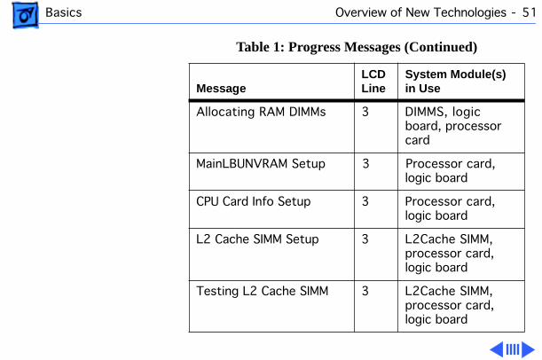
On startup, the server executes the power-on self test, and then displays the ROM version and copyright information on the LCD. It then starts a series of tests, during which the ROM version and the parity DRAM size remain on the display.
During the test phase of the startup process, the server displays startup progress messages on the LCD display. Table 1 lists the progress messages along with the system module(s) in use.

Basics Overview of New Technologies - 49
Table 1: Progress Messages
MessageLCD Line
System Module(s) in Use
DRAM test #1 Begins 3 DIMMs, logic board
ROM SIMM Test Begins 3 ROM SIMM, logic board, processor card
DRAM test #2 Begins 3 DIMMS, logic board, processor card
LONG DRAM test Begins 3 DIMMS, logic board, processor card

Basics Overview of New Technologies - 50
Turning on Caches 3 Cache DIMM, processor card, logic board
Jumping to RAM Prog 3 DIMMS, logic board
Testing Parity DIMMs 3 DIMMs, logic board
MainLBU Enet Setup 3 Logic board
Sounding Boot Beep 3 Logic board
Sizing RAM DIMMs 3 DIMMs
ROM SIMM Data Access 3 ROM SIMM
Table 1: Progress Messages (Continued)
MessageLCD Line
System Module(s) in Use
Basics Overview of New Technologies - 51
Allocating RAM DIMMs 3 DIMMS, logic board, processor card
MainLBUNVRAM Setup 3 Processor card, logic board
CPU Card Info Setup 3 Processor card, logic board
L2 Cache SIMM Setup 3 L2Cache SIMM, processor card, logic board
Testing L2 Cache SIMM 3 L2Cache SIMM, processor card, logic board
Table 1: Progress Messages (Continued)
MessageLCD Line
System Module(s) in Use

Basics Overview of New Technologies - 52
If the server stops (“freezes” or “hangs”) with one of the progress messages displayed, the information indicated may be used to identify the module(s) in use. The module(s) might have failed, be incorrectly installed, or be incompatible.
RAM/ROM/NVRAM: PASSED
3
Table 1: Progress Messages (Continued)
MessageLCD Line
System Module(s) in Use

Basics Overview of New Technologies - 53
After all the tests are complete, the LCD will display something similar to this:
ROM ver.1.1.20.1
0048 MB Parity DRAM
150 MHz 604, 50 MHz Bus
1024 KB Level 2 Cache
If the server is unable to load the operating system from a CD or hard drive, a problem may have been found during startup. Problem messages displayed by the server are listed in Table 2.
Note: The module(s) identified in the problem message might have failed, be incorrectly installed, or be incompatible.

Basics Overview of New Technologies - 54
Table 2: Problem Messages
MessageLCD Line Module(s)
L2 Cache SIMM Failed 1
ROM SIMM Failed 1
MainLBUNVRAM Failed 1 Located on logic board.
RAM DIMM 1A failed at Address xxxxxxxx
1 RAM DIMMS identified as 1A-4A and 1B-4B. Addresses are in hexadecimal.

Basics Overview of New Technologies - 55
MainLBUVideo ID Bad 1 Video subsystem is located on logic board.
MainLBU825#1 Failed 1 SCSI controller #1 is located on logic board.
MainLBU825#2 Failed 1 SCSI controller #2 is located on logic board.
Drive Fan Failed! 1 Fan on right when facing rear of server unit.
Table 2: Problem Messages (Continued)
MessageLCD Line Module(s)

Basics Overview of New Technologies - 56
Processor Fan Failed 1 Fan on left when facing server unit.
Temperature Too Hot! 1 Internal cabinet is unsafe. Shut down system immediately.
Temperature Warning! 1 Internal cabinet temperature is becoming unsafe.
Left Power Fail! 1 Power supply on left when facing front of server unit.
Table 2: Problem Messages (Continued)
MessageLCD Line Module(s)

Basics Overview of New Technologies - 57
Right Power Fail! 1 Power supply on right when facing front of server unit (Network Server 700 Series only).
Left Power Hot! 1 Power supply on left when facing front of server unit.
Right Power Hot! 1 Power supply on right when facing front of server unit (Network Server 700 Series only).
CudaNotResponding!!! 1 Logic board.
Table 2: Problem Messages (Continued)
MessageLCD Line Module(s)

Basics Overview of New Technologies - 58
During long memory test, the server provides additional information by placing consecutive dashes on line 4 of the LCD display. Should the system freeze during the long memory test, use the dash count to identify the DIMM last tested. Table 3 lists the dash count and the DIMM slot tested.
ParityAddrAtAddrFail 1 Logic board.
Table 2: Problem Messages (Continued)
MessageLCD Line Module(s)

Basics Overview of New Technologies - 59
Table 3: DIMM Slot Testing
Number of Dashes Displayed DIMM Slot
1 Main board logic unit DRAM (reserved for future use)
2 Main board logic unit DRAM (reserved for future use)
3 1A
4 1B
5 1A
6 1B
7 2A

Basics Overview of New Technologies - 60
8 2B
9 2A
10 2B
11 3A
12 3B
13 3A
14 3B
15 4A
16 4B
Table 3: DIMM Slot Testing (Continued)
Number of Dashes Displayed DIMM Slot

Basics Overview of New Technologies - 61
17 4A
18 4B
Table 3: DIMM Slot Testing (Continued)
Number of Dashes Displayed DIMM Slot

Basics Configuring the SCSI ID Cable - 62
Configuring the SCSI ID Cable
When you install a drive in a drive carrier, the way you connect the SCSI ID cable to the drive depends on which type of drive you’re installing. This section describes how to connect the SCSI ID cable for the 2 gigabyte (GB) and 4 GB IBM and Seagate hard drives, which are provided by Apple for the Network Server 500 and 700 Series. If you install a Quantum drive or other drive with an active high LED signal, you need to rewire the SCSI cable as described later in this section.
The figure on this page shows the location of the SCSI ID cable.
SCSI Cable Connector to Hard Drive
SCSI Connector on Hard Drive

Basics Configuring the SCSI ID Cable - 63
Connecting IBM and Seagate Drives (2, 4, and 9 GB)
The IBM and Seagate drives (2, 4, and 9 GB) use a Type 1 cable. This cable connects to the drive board at the back of the drive tray and to the SCSI connector on the hard drive. The Type 1 SCSI cable includes a six-pin connector and a four-pin connector. Check which kind of drive you have, then connect the cable to the drive according to the figure on this page.
Configuring SCSI ID Cable
Wire
Open Connector
Seagate 2 GB model #ST32550W drive and Seagate 4 GB model #ST15150W drive
IBM 2 GB model #DFHS-S2W, IBM 4 GB model #DFHS-S4W,Seagate 9 GB model #ST19171, and Quantum or other drives with active high LED signal
Rotate connectorto change connectorconfiguration
End view of connector

Basics Configuring the SCSI ID Cable - 64
Rewiring Quantum Drives and Drives with Active High LEDs
To install a Quantum drive or other drive with an active high LED, you must remove the wire that connects to pin 3 on the drive tray connector, then insert the wire at pin 1. After you rewire the SCSI ID cable, connect the cable to the drive.
1 2 3 4 5 6 1 2 3456

Basics SCSI ID Cable Connector Matrix - 65
SCSI ID Cable Connector Matrix
The SCSI ID Cable Matrix on this page shows the different kinds of SCSI ID connectors used in the Network Server 500 and 700 Series. You must use the correct “type” cable with each drive listed.
SCSI Drive Cables Connectors Drives
Type 1
Type 2
Type 3
Type 4
1.2 GB Hard Drive
2, 4, and 9 GBHard Drives
and8mm Tape Drive
DAT Drive
CD-ROM Drives

Basics Keylock Positions - 66
Keylock Positions
The figure on this page shows the three different keylock positions (service, unlocked, and locked) used in the Network Server 500 and 700 Series. It also indicates the modules that may be accessed from each position.
Left Position:Service
Upright Position:Unlocked
Right Position:Locked
A c c e s s A v a i l a b l e :
• Front Door• Base Door• Rear Drawer• Power Supply• Front Bezel Assembly• Top Shelf• Bottom Shelf
• Front Door• Base Door• Power Supply• Top Shelf• Bottom Shelf
• Drive Trays ( If the front door is positioned properly)

Service Source
K
Specifications
Network Server 500 and700 Series

Specifications Processor - 1
Processor
CPU
Network Server 500/132
PowerPC 604 RISC microprocessor running at 132 MHz Built-in FPU32 KB of on-chip cacheRequires AIX version 4.1.4 or higher
Network Server 700/150
PowerPC 604 RISC microprocessor running at 150 MHz Built-in FPU32 KB of on-chip cacheRequires AIX version 4.1.4 or higher
Network Server 700/200
PowerPC 604e RISC microprocessor running at 200 MHz Built-in FPU64 KB of on-chip cacheRequires AIX version 4.1.4.1 or higher recommended

Specifications Memory - 2
Memory
DRAM
Uses 168-pin, 72-bit, 60 ns (parity) or 70ns (non-parity) DRAM DIMMs
Network Server 500/132
32 MB standard expandable to 512 MB
Network Server 700 Series
48 MB standard expandable to 512 MB
ROM
4 MB ROM
Clock/Calendar
CMOS custom circuitry with long-life lithium battery

Specifications Memory - 3
Memory
Cache
Network Server 500/132
512 KB of Level 2 cache
Network Server 700 Series
1 MB of Level 2 cache

Specifications I/O Interfaces - 4
I/O Interfaces
SCSI
Two Fast/Wide SCSI-2 channels (which support internal devices) and one SCSI-1 channel (which supports external devices).
Network Server 500/132
A total of 14 SCSI devices (seven internal and seven external) can be connected to the server without adding additional PCI cards.
Network Server 700 Series
A total of 16 SCSI devices (nine internal and seven external) can be connected to the server without adding additional PCI cards.
Serial
Two RS-232/RS-422 serial ports compatible with LocalTalk and GeoPort cables; mini DIN-8 connectors
ADB
One Apple Desktop Bus port for a keyboard, mouse, or a three-button mouse.

Specifications I/O Interfaces - 5
I/O Interfaces
Ethernet
Built-in Ethernet (AAUI port)
Video
SuperVGA (SVGA) port requires an HDI-15 cable.
PCI
Six PCI expansion slots, compatible with all PCI 2.0 specifications-compliant cards (not NuBus-compatible)

Specifications Sound and Video - 6
Sound and Video
Sound
16-bit stereo sound input and output ports.
Video
Built-in 1024 x 768, 800 x 600, 640 x 480 video support for 14-inch, 15-inch, 17-inch, and 20-inch monitors.
The following table shows the image size for monitors connected to the monitor port, along with the number of colors or grays supported:

Specifications Sound and Video - 7
Video
Hz ResolutionColors or Grays
60 640 x 480 256
70 640 x 480 256
72 640 x 480 256
60 800 x 600 256
72 800 x 600 256
75 800 x 600 256
60 1024 x 768 256
72 1024 x 768 256
75 1024 x 768 256

Specifications I/O Devices - 8
I/O Devices
Keyboard
Supports Apple ADB keyboards (AIX requires an extended keyboard for installation)
Mouse
Supports all models of the Apple ADB

Specifications Disk Storage - 9
Disk Storage
Hard Drive
1.2, 2, 4, or 9 GB Fast/Wide SCSI internal hard drives
Floppy Drive
One Apple SuperDrive 1.4 MB floppy drive
CD-ROM Drive
Network Server 500/700 Series
One internal AppleCD 600i 4X-speed CD-ROM drive
Network Server 700 Series
One internal AppleCD 1200i 8X-speed CD-ROM drive
DDS-2 DAT Drive
Optional 3.5-inch DDS-2 DAT drive

Specifications Disk Storage - 10
8 mm Tape Drive
Optional 8 mm tape drive
Data capacity
22 meter tape: 5 GB compressed, 2.5 GB uncompressed170 meter tape: 40 GB compressed, 20 GB uncompressed
Maximum data trasfer rate
6 MB/sec compressed, 3 MB/sec uncompressed
Tape compatibility
Advanced metal evaporated (AME) tapesNote: The 8 mm tape drive can read from but not write to standard
metal particle tapes. The tape heads must be cleaned after reading from a standard metal particle tape before an AME tape can be used.

Specifications Electrical - 11
Electrical
Line Voltage
100–240 V AC, RMS single phase (automatically configured)
Frequency
50–60 Hz, single phase
Maximum Power
AC Power: 708W maximum (not including monitor)
Power Supply
Network Server 500/132
Single, 325 W
Network Server 700 Series
One or two 425 W, hot-swappable, supply(ies)

Specifications Electrical - 12
*+3.3 and +5.5 power outputs are traded off; total power for both not to exceed 180 watts for the LE, 260 watts for the HE
Current TypeNetwork Server 500 Series
Network Server 700 Series
+3.3 V* 25.0 A 50.0 A
+5 V* 28.0 A 44.0 A
+12 V 2.0 A
+12 V (normal) 11.0 A 13.0 A
+12 V (start up) 18.0 A (12 seconds maximum)
–12 V 100 mA 100 mA

Specifications Electrical - 13
Power Requirements
Apple Desktop Bus
Maximum power draw for all ADB devices: 500 milliampere (mA)Apple mouse draws up to 10 mAKeyboard draws 25–80 mA (varies with keyboard model used)
Note:
It is recommended that you connect no more than three ADB devices to the Network Server.
Expansion Cards and Devices
If you add a PCI expansion card, or an internal SCSI device to your server, make sure the component doesn’t exceed its maximum power allowance from the different voltage sources. Note that no single PCI card should exceed the 25 watt limit of the PCI Revision 2.1 specification. Follow the guidelines outlined in the following table:

Specifications Electrical - 14
For SCSI devices, the average (thermal) power consumption per
Network Server Model Voltage Current Total Power
Network Server 500/132
+3.3 V 10.0 A Not to exceed 50.0 +5 V10.0 A watts in any combination
+5 V 10.0 A
+12 V 2.0 A
Network Server 700 Series
+3.3 V 18.0 A Not to exceed 90.0 watts in any combination
+5 V 18.0 A
+12 V 2.0 A
Specifications Electrical - 15
drive bay is1.1 amps at +5 volts and 1.3 amps at +12 volts. Apple recommends that drives be configured for spin-up on command.

Specifications Physical - 16
Physical
Dimensions
Height:
24.5 inchWidth: 16.5 inchDepth: 18 inch
Weight
84–92 lb. (exact weight varies depending on number and type of internal SCSI devices installed)
Specifications Environmental - 17
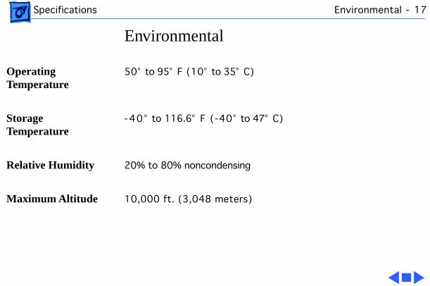
Environmental
Operating Temperature
50° to 95° F (10° to 35° C)
Storage Temperature
-40° to 116.6° F (-40° to 47° C)
Relative Humidity
20% to 80% noncondensing
Maximum Altitude
10,000 ft. (3,048 meters)

Service Source
K
Troubleshooting
Network Server 500 and700 Series
Troubleshooting General - 1
General
The Symptom Charts included in this chapter will help you diagnose specific symptoms related to your product. Because cures are listed on the charts in the order of most likely solution, try the first cure first. Verify whether or not the product continues to exhibit the symptom. If the symptom persists, try the next cure. (Note: If you have replaced a module, reinstall the original module before you proceed to the next cure.)
If you are not sure what the problem is, or if the Symptom Charts do not resolve the problem, refer to the Flowchart for the product family.
For additional assistance, contact Apple Technical Support.
Troubleshooting Cleaning Procedure for Card Connectors - 2
Cleaning Procedure for Card Connectors
A small number of cards for the Network Server may contain residue on the gold edge connector pins, which may cause a variety of intermittent symptoms.
To correct the problem, inspect the connector pins with a magnifying glass. If you find residue, use a pencil eraser to gently clean the pins.

Troubleshooting Symptom Charts/Power - 3
Symptom Charts
Power
System does not power up, screen is blank, fan is not running, power LED is not lit
1 Verify that system is properly connected to a power source:• Check for the presence of power cable.• If the server is plugged into a power strip, verify that the
power strip is turned on.• Check power cable connection. It should be firmly
connected to the server and the power source.• Plug the monitor directly into wall socket and then verify
that the monitor has power.2 Verify that key in rear drawer is in horizontal (locked)
position.3 Verify that power supply is installed and properly seated.4 Verify that power LED is on.5 Verify that rear drawer is properly installed.6 Verify that toggle bolts on rear of logic board are fully

Troubleshooting Symptom Charts/Power - 4
tightened.7 Check to see if server frame is bent slightly, preventing
micro switch in rear of server from making contact. (Note: When facing rear of network server, micro switch is located near lower left edge of logic board face plate.There is a plastic protrusion that inserts into a slot in the chassis. The micro switch is visible through the grill.)
8 Verify that metal ground strip is properly installed on logic board.
9 Reseat processor card.10 Reseat other PCI cards.11 Reseat cache DIMM.12 Verify that all DRAM DIMMs are properly installed. Remove
all DRAM DIMMs and replace them one at a time to test. Replace any bad DIMMs.
13 Plug in keyboard and press power-on switch on keyboard. If system does not power on, replace power supply. If system does power on, try turning off system from front panel

Troubleshooting Symptom Charts/Power - 5
switch. If machine does not power down, replace NMI reset switch cable.
14 Reset Cuda chip. (Refer to “The Cuda Chip” in Basics chapter for instructions.)
15 Reseat logic board and make sure logic board interconnect is making fully connection.
16 Reset logic board. (Refer to “Resetting the Logic Board” in Basics chapter for instructions.)
17 Replace power cord.18 Replace rear micro switch.19 Replace power supply.20 Replace on/off switch.21 Replace front keyswitch.22 Replace powerplane interconnect board.23 Replace logic board. Retain customer’s DIMMs.

Troubleshooting Symptom Charts/Startup - 6
Startup
Cannot boot system from hard drive
1 Verify system software is installed on the hard drive. If not, refer to “Using AIX, AppleTalk Services, and Mac OS Utilities on the Network Server” for information about installing and using the operating system.
2 Verify that the server successfully booted from this hard drive before. If not, refer to “Using AIX, AppleTalk Services, and Mac OS Utilities on the Network Server” for information about installing and using the operating system.
3 Using Open Firmware, verify system startup path is configured for the correct hard drive.
4 If a problem message is displayed on the LCD during the startup process, refer to “LCD Panel and Diagnostics” in Basics chapter to determine the problem component.

Troubleshooting Symptom Charts/Startup - 7
5 If a three-digit error code is displayed on the LCD, refer to “Chapter 10: Troubleshooting” of “Using AIX, AppleTalk Services, and Mac OS Utilities on the Network Server” for information on error codes and recommended action.
6 Run Network Server Diagnostic Utility and follow the instructions provided with the utility to verify core system operations.
7 If the internal rear hard drive is the boot drive (Network Server 700 Series only), verify that the hard drives are properly connected and terminated. If the server does not boot,• Replace the rear drives SCSI cable• Replace the rear drives SCSI ID Cable• Replace the rear drives power cable• Replace the power backplane-to-SCSI backplane cable• Replace SCSI backplane• Replace power backplane• Replace hard drive

Troubleshooting Symptom Charts/Startup - 8
8 If the boot drive is in the front drive bay, move the hard drive to another front drive bay slot and try starting up the server.
Note:
You may have to reconfigure the system startup path using Open Firmware. If the server does not boot,• Replace the 68-pin SCSI hard drive cable• Replace SCSI ID cable• Replace hard drive power cable• Replace SCSI backplane• Replace hard drive
9 Replace logic board. Retain customer’s DIMMs.10 Replace processor card.
Long DRAM test never completes
Verify that each DRAM DIMM is properly seated.
Troubleshooting Symptom Charts/Startup - 9
System will not boot and a memory failure is indicated on lines 1 and 2 of the LCD with ECCBEBAD as the failed address
Verify DIMM specifications. ECC memory DIMMs with non-quad CAS logic are not supported.
Server does not beep at startup or when “beep” command is issued in AIX
Disable ROM checksum in Power-On-Self-Test (POST).
Note:
For details, see Technical Information Library, article number 19814, “Network Server 500 or 700 No Sound at Startup or in AIX.”

Troubleshooting Symptom Charts/System - 10
System
Clicking, chirping, or thumping
Note:
Noises may not necessarily require a replacement of component. For example, a noisy fan may be more annoying than a cause of concern.
1 Verify that fan unit(s) is not loose. Replace if necessary. Fan unit(s) is hot-swappable and can be replaced without shutting down server.
2 Verify that power supply is properly seated. Replace if necessary. Network Server 700 Series power supply is hot-swappable and may be replaced without shutting down server.
3 Verify that all front drive trays are completely inserted.4 Check hard drive(s). Replace if necessary.5 Check DAT drive. Replace if necessary.6 Check floppy drive. Replace if necessary.7 Replace logic board. Retain customer’s DIMMs.8 Replace processor card.

Troubleshooting Symptom Charts/System - 11
System shuts down intermittently
1 Verify that power cord is firmly plugged in.2 Verify that fans are working. Replace if necessary.3 Verify that all front drive trays are completely inserted.
Improper installation may disrupt air flow.4 Verify that air vents are clear. Thermal-protection circuit
may shut down system. After 30 – 40 minutes, system should be OK.
5 Run Network Server Diagnostic Utility and follow the instructions provided with the utility to verify core system operations.
6 Check battery.7 Reset Cuda chip. (Refer to “The Cuda Chip” in Basics chapter
for instructions.)8 Reset logic board. (Refer to “Resetting the Logic Board” in
Basics chapter for instructions.)9 Replace power cord.10 Replace power supply.11 Replace powerplane interconnect board.

Troubleshooting Symptom Charts/System - 12
12 Replace logic board. Retain customer’s DIMMs.13 Replace processor card.
System intermittently crashes or hangs
1 Verify that power cord is firmly connected.2 Verify that power supply is properly seated.3 Verify that rear drawer is properly seated.4 Verify that all front drive trays are properly seated.5 Verify system software is version 4.1.4 or later. (Refer to
“Using AIX, AppleTalk Services, and Mac OS Utilities on the Network Server” for information on installing and using the operating system).
6 Run Network Server Diagnostic Utility and follow the instructions provided with the utility to verify core system operations.
7 Verify that system is using fast-paged mode, 60ns or faster RAM access time DIMMs.
8 Reseat processor card.9 Reseat cache DIMM.

Troubleshooting Symptom Charts/System - 13
10 Remove all DRAM DIMMs and replace them one at a time to test. Replace any bad DIMMs.
11 Remove all PCI cards and test unit. If problem does not occur with cards removed, replace them one at a time to determine which card is causing the problem. Replace problem card with known-good card.
12 Replace logic board. Retain customer’s DIMMs.13 Replace processor card.
System is inactive 1 Verify that power LED is on.2 Check for three-digit error code on LCD panel. If display is
not blank, refer to “Chapter 10: Troubleshooting” in “Using AIX, AppleTalk Services, and Mac OS Utilities on the Network Server” for possible error codes and recommended actions.
3 Verify that all cables are properly connected and secure.4 Adjust brightness on monitor.5 Use Control-D or Control-C to cancel any stalled processes.

Troubleshooting Symptom Charts/System - 14
6 Verify that key in rear drawer is in horizontal (locked) position.
7 Restart system.8 Run Network Server Diagnostic Utility and follow the
instructions provided with the utility to verify core system operations.
Three-digit error code is displayed on LCD panel during startup process
For possible error codes and recommended actions, refer to “Chapter 10: Troubleshooting” of “Using AIX, AppleTalk Services, and Mac OS Utilities on the Network Server.”

Troubleshooting Symptom Charts/Video - 15
Video
Screen is black, drive operates, and fan is running
1 Verify that the monitor is a SVGA or Multiple Scan model.2 If the system is using a video extender cable, verify that it is
rated for use with Multiple Scan monitors. 3 Adjust brightness on monitor.4 Verify that monitor cable is firmly attached to both the
monitor and server.5 Verify that the system is configured to connect to a serial
terminal. (For information on how to connect the Network Server to a serial terminal refer to “Connecting a serial terminal” in Chapter 3 of “Setting Up the Network Server.”)
6 Run Network Server Diagnostic Utility and follow the instructions provided with the utility to verify core system operations.
7 Reset Cuda chip. (Refer to “The Cuda Chip” in Basics chapter for instructions.)

Troubleshooting Symptom Charts/Video - 16
8 Reset logic board. (Refer to “Resetting the Logic Board” in Basics chapter for instructions.)
9 Test with known-good monitor. Replace monitor if necessary. Refer to appropriate monitor manual to troubleshoot defective monitor.
10 Replace monitor cable.11 Replace logic board. Retain customer’s DIMMs.12 Replace processor card.
Screen lights up, but nothing is displayed on screen
1 Verify that the monitor is a SVGA or Multiple Scan model.2 If the system is using a video extender cable, verify that it is
rated for use with Multiple Scan monitors. 3 Reset Cuda chip. (Refer to “The Cuda Chip” in Basics chapter
for instructions.)4 Reset logic board. (Refer to “Resetting the Logic Board” in
Basics chapter for instructions.)

Troubleshooting Symptom Charts/Video - 17
5 Test with known-good monitor. Replace monitor if necessary. Refer to appropriate monitor manual to troubleshoot defective monitor.
6 Run Network Server Diagnostic Utility and follow the instructions provided with the utility to verify core system operations.
7 Replace monitor cable.8 Replace logic board. Retain customer’s DIMMs.9 Replace processor card.
Screen has white area with blotches of color
1 Move unit to another location.2 Degauss display with manual degaussing coil. (Degaussing
coil can be purchased at most major electronic parts stores.)
Size of text/graphics differs at top, bottom, or sides of screen
1 Replace monitor cable.2 Replace monitor.

Troubleshooting Symptom Charts/Video - 18
Out of focus 1 Perform focus adjustment.2 Replace monitor.
Black screen spots Replace monitor.
Screen jitters or flashes
1 Verify that the monitor is a SVGA or Multiple Scan model.2 If the system is using a video extender cable, verify that it is
rated for use with Multiple Scan monitors. 3 Verify that monitor cable is firmly attached to both monitor
and server.4 Check for external interference.5 Replace monitor.
Objects on screen appear too large or distorted
Adjust display resolution. (Refer to “Chapter 10: Troubleshooting” in “Using AIX, AppleTalk Services, and Mac OS Utilities on the Network Server.”)

Troubleshooting Symptom Charts/SCSI Devices General - 19
SCSI Devices General
Server does not recognize SCSI device(s)
Note:
When troubleshooting SCSI devices, use this procedure to display information regarding which SCSI devices are currently recognized by the server.
Note:
You may either use the Network Server Diagnostic Utility or Open Firmware to determine which SCSI devices are installed.
1 Turn the front key to the upright (unlocked) position.2 Turn on the server. If the server is already powered on,
press the reset button. If AIX is running, shut down the system by executing the shutdown -r command.
3 While the system is resetting (or starting up), hold down the Command-Option-OF keys until the 0> prompt appears.
4 To use Network Server Diagnostic Utility insert the utility disk into the floppy drive and enter the command
boot fd:diags
. Follow the instructions provided with the utility for verifying SCSI devices are installed.
Troubleshooting Symptom Charts/SCSI Devices General - 20
5 To use Open Firmware enter the login command at the 0> prompt and then enter password at the OF Password prompt. Enter the appropriate probe-scsi command. For example, •
probe-scsi0
to display the devices on the built-in external SCSI bus
•
probe-scsi1
to display devices on the first internal SCSI bus
•
probe-scsi2
to display devices on the second internal SCSI bus
6 System displays the SCSI ID, logical unit, device type, manufacturer, model, and firmware version of SCSI devices it recognizes on the SCSI bus.
7 If you do not see SCSI ID of problem device, check device for proper SCSI termination, SCSI ID, and cable connection. (Refer to “Setting Up Your Server and Connecting External Devices” chapter in “Setting Up the Network Server” for more information.)

Troubleshooting Symptom Charts/Hard Drive - 21
Hard Drive
Single internal hard drive in front drive bay doesn’t operate; drive doesn’t spin
1 Verify that hard drive tray is completely inserted in the front drive bay.
2 Verify that server is recognizing the drive on SCSI bus. (Refer to the section “SCSI Devices General” previously in this chapter.)
3 Verify that installed SCSI devices and PCI cards are not exceeding maximum power allowance. This may affect operation of installed devices.
4 Run Network Server Diagnostic Utility and follow the instructions provided with the utility to verify core system operations.
5 Move the hard drive to another front drive bay slot.6 Verify that hard drive SCSI cable, SCSI ID cable, LED cable,
and power cable are properly connected.7 Replace hard drive power cable.8 Replace hard drive SCSI cable.

Troubleshooting Symptom Charts/Hard Drive - 22
9 Replace hard drive SCSI ID cable.10 Replace hard drive. (Refer to “Setting Up the Network
Server” for information on installing disk drives.)11 Replace SCSI backplane interconnect board.
Single internal hard drive in the rear drive bracket doesn’t operate; drive doesn’t spin
Note:
This procedure applies only to Network Server 700 Series.
1 Verify that server is recognizing the internal rear hard drive on SCSI bus. (Refer to the section “SCSI Devices General” previously in this chapter.)
2 Verify that installed SCSI devices and PCI cards are not exceeding maximum power allowance. This may affect operation of installed devices.
3 Run Network Server Diagnostic Utility and follow the instructions provided with the utility to verify core system operations.

Troubleshooting Symptom Charts/Hard Drive - 23
4 Verify that internal rear hard drive SCSI cable, SCSI ID cable, and power cable are properly connected.
5 Verify that the last bracket-mounted drive on the SCSI cable has termination enabled.
6 If the rear drive bracket contains just one hard drive, verify that it is connected to the last connector on the SCSI cable.
7 If the rear drive bracket contains two hard drives, verify that the SCSI ID cable and the last connector on the SCSI cable are both connected to the bottom hard drive.
8 Verify that power backplane-to-SCSI backplane cable is properly connected.
9 Verify that 10-inch and 20-inch mezzanine-to-SCSI backplane cables are properly connected.
10 Replace rear drive power cable.11 Replace rear drive SCSI cable.12 Replace rear drive SCSI ID cable.13 Replace 10-inch and 20-inch mezzanine-to-SCSI backplane
cables.

Troubleshooting Symptom Charts/Hard Drive - 24
14 Replace SCSI backplane interconnect board.15 Replace hard drive. (Refer to “Setting Up the Network
Server” for information on installing disk drives.)
No internal hard drive in front drive bay operates
1 Verify that all hard drive trays are completely inserted in their respective front drive bay.
2 Verify that server is recognizing the hard drives in the front drive bays on SCSI bus. (Refer to the “SCSI Devices General” previously in this chapter.)
3 Verify that installed SCSI devices and PCI cards are not exceeding maximum power allowance. This may affect operation of installed devices.
4 Run Network Server Diagnostic Utility and follow the instructions provided with the utility to verify core system operations.
5 Verify that power backplane-to-SCSI backplane cable is properly connected.

Troubleshooting Symptom Charts/Hard Drive - 25
6 Verify that 10-inch and 20-inch mezzanine-to-SCSI backplane cables are properly connected.
7 Replace 10-inch and 20-inch mezzanine-to-SCSI backplane cables.
8 Replace power backplane-to-SCSI backplane power cable.9 Replace SCSI backplane interconnect board.10 Replace powerplane interconnect board.11 Replace logic board. Retain customer’s DIMMs.12 Replace processor card.
No internal hard drives in the rear drive bracket operate
Note:
This procedure applies only to Network Server 700 Series.
1 Verify that internal hard drives in the rear drive bracket do not have duplicate SCSI device addresses.
2 Verify that server is recognizing the internal rear hard drives on SCSI bus. (Refer to the “SCSI Devices General” previously in this chapter.)

Troubleshooting Symptom Charts/Hard Drive - 26
3 Verify that installed SCSI devices and PCI cards are not exceeding maximum power allowance. This may affect operation of installed devices.
4 Run Network Server Diagnostic Utility and follow the instructions provided with the utility to verify core system operations.
5 Verify that rear drives SCSI cable, SCSI ID cable, and power cable are properly connected.
6 Verify that the last bracket-mounted drive on the SCSI cable has termination enabled.
7 Verify that the SCSI ID cable and the last connector on the SCSI cable are both connected to the bottom hard drive.
8 Verify that power backplane-to-SCSI backplane cable is properly connected.
9 Verify that 10-inch and 20-inch mezzanine-to-SCSI backplane cables are properly connected.
10 Replace rear drives SCSI cable.11 Replace rear drives SCSI ID cable.

Troubleshooting Symptom Charts/Hard Drive - 27
12 Replace rear drives power cable.13 Replace 10-inch and 20-inch mezzanine-to-SCSI backplane
cables.14 Replace SCSI backplane interconnect board.15 Replace power backplane-to-SCSI backplane power cable.16 Replace powerplane interconnect board.17 Replace logic board. Retain customer’s DIMMs.18 Replace processor card.

Troubleshooting Symptom Charts/Floppy Drive - 28
Floppy Drive
Internal floppy drive does not operate
1 Use a known-good floppy disk.2 Verify that mezzanine-to-floppy drive cable is properly
connected.3 Verify that rear drawer is properly installed.4 Replace floppy drive.5 Replace mezzanine-to-floppy drive cable.6 Replace mezzanine interconnect board.7 Replace logic board. Retain customer’s DIMMs.
Does not eject disk 1 To eject a previously inserted disk, insert an opened paper clip into hole beneath floppy drive.
2 Reseat floppy drive bezel and floppy drive so that bezel slot aligns correctly with floppy drive.
3 Verify that rear drawer is properly installed.4 Replace floppy drive.5 Replace mezzanine-to-floppy drive cable.

Troubleshooting Symptom Charts/Floppy Drive - 29
6 Replace mezzanine interconnect board.7 Replace logic board. Retain customer’s DIMMs.
Troubleshooting Symptom Charts/CD-ROM Drive - 30
CD-ROM Drive
CD-ROM drive does not work
1 Use a known-good compact disc.2 Reseat CD-ROM drive.3 Move CD-ROM drive to another front drive bay slot.4 Verify that server is recognizing CD-ROM drive on SCSI bus.
(Refer to “SCSI Devices General” in this chapter.)5 Verify that installed SCSI devices and PCI cards are not
exceeding maximum power allowance. This may effect operation of installed devices.
6 Run Network Server Diagnostic Utility and follow the instructions provided with the utility to verify core system operations.
7 Verify that CD-ROM drive SCSI cable, SCSI ID cable, and power cable are properly connected.
8 Replace CD-ROM drive.9 Replace SCSI backplane board.10 Replace logic board. Retain customer’s DIMMs.

Troubleshooting Symptom Charts/CD-ROM Drive - 31
Volume control does not operate correctly
1 Reseat CD-ROM drive.2 Move CD-ROM drive to another front drive bay slot.3 Verify that CD-ROM drive SCSI cable, SCSI ID cable, and
power cable are properly connected.4 Replace CD-ROM drive.5 Replace SCSI backplane board.6 Replace logic board. Retain customer’s DIMMs.

Troubleshooting Symptom Charts/DAT Drive - 32
DAT Drive
DAT drive does not work
1 Verify that DAT tape conforms to DDS-2 standards.2 Use a known-good tape.3 Move the DAT drive to another front drive bay slot.4 Verify that server is recognizing DAT drive on SCSI bus.
(Refer to “SCSI Devices General” in this chapter.)5 Verify that installed SCSI devices and PCI cards are not
exceeding maximum power allowance. This may affect operation of installed devices.
6 Run Network Server Diagnostic Utility and follow the instructions provided with the utility to verify core system operations.
7 Verify that DAT drive SCSI cable, SCSI ID cable, and power cable are properly connected.
8 Replace DAT drive.9 Replace SCSI backplane board.10 Replace logic board. Retain customer’s DIMMs.

Troubleshooting Symptom Charts/DAT Drive - 33
Self-test fails and right light flashes amber
Clean tape drive head. (Refer to “Cleaning the Tape Drive Heads” in “Setting Up the Network Server.”)
Amber light flashes when tape is loaded in tape drive
Copy data to new tape and discard old tape, as it is worn out.
Self-test fails and right light is solid amber
1 Move DAT drive to another front drive bay slot.2 Replace DAT drive.3 Replace SCSI backplane board.4 Replace logic board. Retain customer’s DIMMs.

Troubleshooting Symptom Charts/Peripherals - 34
Peripherals
Cursor does not move 1 Check mouse connection.2 Inspect inside of mouse for buildup of dirt or other
contaminants. Clean mouse if necessary.3 If mouse was connected to keyboard, connect mouse to
computer ADB port instead. If mouse works, replace keyboard.
4 Replace ADB cable.5 If mouse does not work in any ADB port on computer, replace
mouse.6 Replace logic board. Retain customer’s DIMMs.7 Replace processor card.
Troubleshooting Symptom Charts/Peripherals - 35
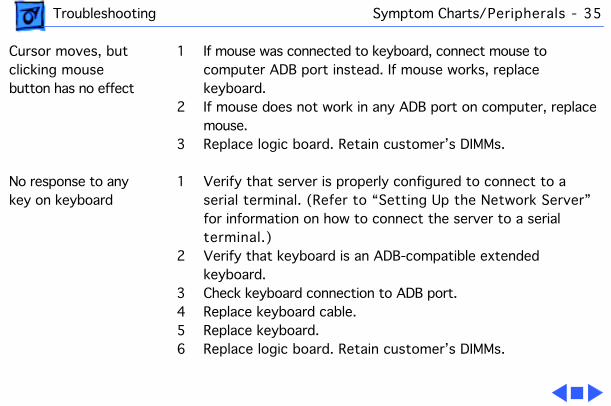
Cursor moves, but clicking mouse button has no effect
1 If mouse was connected to keyboard, connect mouse to computer ADB port instead. If mouse works, replace keyboard.
2 If mouse does not work in any ADB port on computer, replace mouse.
3 Replace logic board. Retain customer’s DIMMs.
No response to any key on keyboard
1 Verify that server is properly configured to connect to a serial terminal. (Refer to “Setting Up the Network Server” for information on how to connect the server to a serial terminal.)
2 Verify that keyboard is an ADB-compatible extended keyboard.
3 Check keyboard connection to ADB port.4 Replace keyboard cable.5 Replace keyboard.6 Replace logic board. Retain customer’s DIMMs.

Service Source
K
Take Apart
Network Server 500 and700 Series

Take Apart Base Door - 1
Base Door
No preliminary steps are required before you begin this procedure.
Note:
Turn the front lock key to the upright (unlocked) or left (service) position otherwise the lock shaft may be damaged.

Take Apart Base Door - 2
1 Press the two buttons, located on the left and right inside edge of the base door.

Take Apart Base Door - 3
2 Pull the base door out.

Take Apart Fan Assembly - 4
Fan Assembly
No preliminary steps are required before you begin this procedure.

Take Apart Fan Assembly - 5
Note:
Because the fan assembly is hot-swappable, you do not need to shut down the server before replacing the fan assembly. (A message will display on the LCD panel indicating that it is safe to replace the assembly.)
1 With the back of the computer facing you, place your fingers on the notch located on the fan assembly.
2 Press the fan assembly down and away from the unit.

Take Apart Fan Assembly - 6
Replacement Note:
With the fan assembly at a right angle to the unit, install the fan assembly by first inserting the tab, and then pushing the assembly up and into its enclosure. Make sure that the bottom contacts of the fan are inserted correctly.

Take Apart Rear Drawer - 7
Rear Drawer
The rear drawer consists of the following parts:• Fan assembly• Rear I/O panel• Rear keyswitch cable• Logic board w/cards• Logic board carrier• Processor card guides
Before you begin, disconnect the power cord.
Caution:
Always support the rear drawer when removing it or it may fall off the unit.

Take Apart Rear Drawer - 8
Caution:
Review the ESD precautions in Bulletins/Safety.
1 With the back of the computer facing you, turn the key in the rear drawer lock to the upright (unlocked) position.

Take Apart Rear Drawer - 9
2 Loosen the four thumb screws.
Caution:
The following procedure releases the drawer from its drawer slides. Be sure to support the drawer at all times so that it does not fall off the unit.

Take Apart Rear Drawer - 10
3 Slide the drawer out a few inches. With the right hand holding the drawer by the top handle, use the left hand to release the bottom black latch and move the drawer slide 1 inch to the left. Repeat for the top latch and slide.

Take Apart Rear Drawer - 11
4 Detach the rear drawer from the drawer slides and remove it from the unit.
Note:
Always place the rear drawer on an antistatic mat.
Replacement Caution:
In the following procedure, be sure to support the drawer at all times so that it does not fall off the unit.

Take Apart Rear Drawer - 12
Replacement Note:
With your right hand holding the drawer by the top handle, use your left hand to align the bottom drawer slide between the drawer’s mounting rail and the plastic guide. Make sure the hook at the far left end of the drawer slide engages with the notch in the mounting rail. Then move the slide all the way to the right until you hear a click and the black latch locks into place.
Take Apart Rear Drawer - 13
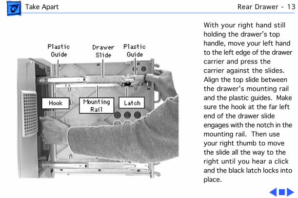
With your right hand still holding the drawer’s top handle, move your left hand to the left edge of the drawer carrier and press the carrier against the slides. Align the top slide between the drawer’s mounting rail and the plastic guides. Make sure the hook at the far left end of the drawer slide engages with the notch in the mounting rail. Then use your right thumb to move the slide all the way to the right until you hear a click and the black latch locks into place.
Take Apart Rear Keyswitch Cable - 14
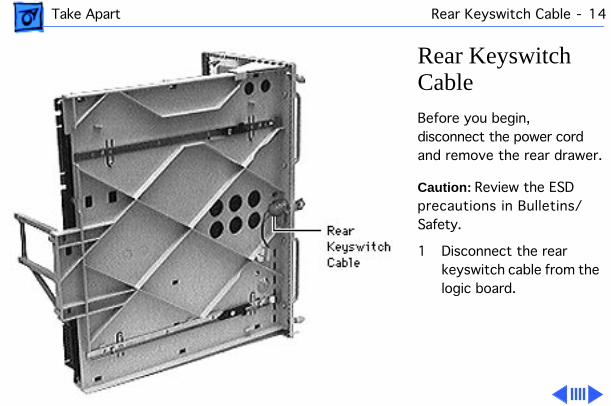
Rear Keyswitch Cable
Before you begin, disconnect the power cord and remove the rear drawer.
Caution:
Review the ESD precautions in Bulletins/Safety.
1 Disconnect the rear keyswitch cable from the logic board.

Take Apart Rear Keyswitch Cable - 15
2 Using pliers, pull out the metal key tab.

Take Apart Rear Keyswitch Cable - 16
3 Unscrew the rear keyswitch cable from the rear I/O panel by turning the nut counterclockwise.

Take Apart Rear I/O Panel - 17
Rear I/O Panel
Before you begin, disconnect the power cord and remove the following:• Rear drawer• Fan assembly• Rear keyswitch cable
Caution:
Review the ESD precautions in Bulletins/Safety.

Take Apart Rear I/O Panel - 18
Remove the four screws that attach the logic board carrier and the rear drawer handles with the rear I/O panel.
Replacement Note:
When replacing the rear I/O panel, you may need to remove the fan cage. Simply push the cage out from the rear I/O panel.

Take Apart Rear Panel - 19
Rear Panel
Before you begin, disconnect the power cord and slide the rear drawer open.
Caution:
Review the ESD precautions in Bulletins/Safety.
1 Loosen the thumb screw.

Take Apart Rear Panel - 20
2 Remove the fan-to-SCSI-backplane cable.
Replacement Note:
Make sure to reconnect the fan-to-SCSI backplane cable to the corret connector on the backplane. The rear drives’ power connector is similar, and if the fan-to-SCSI backplane cable is incor-rectly connected to it, the server will not power on.

Take Apart Top Cover - 21
Top Cover
Before you begin, do the following:• Disconnect the power cord • Slide the rear drawer
open• Remove the rear panel
Caution:
Review the ESD precautions in Bulletins/Safety.

Take Apart Top Cover - 22
1 Remove the two screws from the rear edge of the top cover.
2 Pull the top cover up and away from the main unit.

Take Apart Left Side Panel - 23
Left Side Panel
Before you begin, do the following:• Disconnect the power cord • Slide the rear drawer
open• Remove the rear panel
Caution:
Review the ESD precautions in Bulletins/Safety.

Take Apart Left Side Panel - 24
1 Remove the two screws from the rear edge of the left side panel.
2 Slide the left side panel out.
Replacement Note:
The left side panel can be installed only on the left side of the server.
Replacement Note:
First latch the left side panel on the top and then on the bottom.

Take Apart Right Side Panel - 25
Right Side Panel
Before you begin, disconnect the power cord slide the rear drawer open and remove the rear panel.
Caution:
Review the ESD precautions in Bulletins/Safety.

Take Apart Right Side Panel - 26
1 Remove the two screws from the rear edge of right side panel.
2 Slide the right side panel out.
Replacement Note:
The right side panel can be installed only on the right side of the server.
Replacement Note:
First latch the right side panel on the top and then on the bottom.

Take Apart Drawer Slides - 27
Drawer Slides
Before you begin, disconnect the power cord and remove the following:• Rear drawer• Left side panel

Take Apart Drawer Slides - 28
1 Pull the slides all the way to the rear.

Take Apart Drawer Slides - 29
2 Remove the two screws on each slide and remove the slides.

Take Apart Left Duct - 30
Left Duct
Before you begin, disconnect the power cord and remove the following:• Rear drawer• Left side panel

Take Apart Left Duct - 31
Remove the left duct mounting screw and remove the left duct.

Take Apart AC Interlock Receptacle Ground Cable - 32
AC Interlock Receptacle Ground Cable
Before you begin, disconnect the power cord and remove the following:• Rear drawer• Rear panel• Top cover• Left side panel• Left duct

Take Apart AC Interlock Receptacle Ground Cable - 33
Caution:
Review the ESD precautions in Bulletins/Safety.
1 Remove the nut holding the AC interlock receptacle ground cable.
2 Unscrew the AC interlock receptacle ground cable.

Take Apart Power Supply (NS 500 Series) - 34
Power Supply (NS 500 Series)
Before you begin, disconnect the power cord and remove the following:• Base door• Rear drawer• Rear panel• Top cover• Left side panel• Right side panel• Left duct• AC interlock receptacle
ground cable

Take Apart Power Supply (NS 500 Series) - 35
Caution:
Review the ESD precautions in Bulletins/Safety.
1 Disconnect the Power backplane-to-SCSI backplane cable from the power backplane by depressing the security tabs on the connector.
Take Apart Power Supply (NS 500 Series) - 36
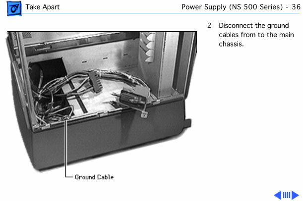
2 Disconnect the ground cables from to the main chassis.

Take Apart Power Supply (NS 500 Series) - 37
3 Disconnect the power supply-to-logic board cable from the power supply.
4 Remove the screw and slide the power supply out of the main unit.

Take Apart Power Supply (NS 700 Series) - 38
Power Supply (NS 700 Series)
Before you begin, turn the front lock key to the upright (unlocked) or left (service) position and remove the base door.
Caution:
Review the ESD precautions in Bulletins/Safety.

Take Apart Power Supply (NS 700 Series) - 39
Note:
Because the power supply is hot-swappable, you do not need to shut down the server before replacing the power supply provided that there are two power supplies installed. (A message will display on the LCD panel indicating that it is safe to replace the power supply.)
Grasp the power supply handle and pull the power supply out of the unit.

Take Apart Power Supply (NS 700 Series) - 40
Replacement Note:
The server includes two bays for two power supplies. Although the server is shipped with only one power supply installed in the left bay, the power supply can be installed in either bay. Always slide the power supply all the way down into the bay, and push the power supply with enough force so that you hear it snap into place.

Take Apart Rear Hard Drives Bracket (NS 700 Series) - 41
Rear Hard Drives Bracket (NS 700 Series)
Before you begin, disconnect the power cord and remove the following:• Rear drawer• Rear panel
Caution:
Review the ESD precautions in Bulletins/Safety.

Take Apart Rear Hard Drives Bracket (NS 700 Series) - 42
1 Disconnect the following:• Rear hard drives
power cable• SCSI cable• SCSI ID cable

Take Apart Rear Hard Drives Bracket (NS 700 Series) - 43
2 Remove the screw that attaches the rear hard drives bracket to the server enclosure and slide the rear hard drives bracket out.

Take Apart Processor Card - 44
Processor Card
Before you begin, disconnect the power cord.
Caution:
Review the ESD precautions in Bulletins/Safety.
Caution:
Hold the processor card by the edges. Never hold the card by the heat sink.
Caution:
Be sure to support the rear drawer with one hand while the other hand pulls the processor card out or puts it back in.

Take Apart Processor Card - 45
1 With the back of the computer facing you, turn the key in the rear drawer lock to the upright (unlocked) position.
2 Loosen the four thumb screws and slide the rear drawer out.
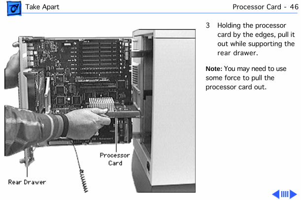
Take Apart Processor Card - 46
3 Holding the processor card by the edges, pull it out while supporting the rear drawer.
Note:
You may need to use some force to pull the processor card out.

Take Apart Processor Card - 47
Replacement Note:
When installing the processor card, position the bottom edges of the card in the processor card guides, and slide the card in until it touches the connector. Then press in on the card so that it is seated firmly into the connector. Do not force the card or you may damage it. Be sure that the card is completely seated, or else the server will not start up.

Take Apart DRAM DIMMs - 48
DRAM DIMMsBefore you begin, disconnect the power cord.
Caution: Review the ESD precautions in Bulletins/Safety.

Take Apart DRAM DIMMs - 49
Caution: Be sure to support the rear drawer with one hand while the other hand pulls the DIMM out or puts it back in.
1 With the back of the computer facing you, turn the key in the rear drawer lock to the upright (unlocked) position.
2 Loosen the four thumb screws and slide the rear drawer out.

Take Apart DRAM DIMMs - 50
3 Push the ejector tab (next to the DIMM socket) outward and down, and pull out the DIMM.
Note: Your Network Server may have two ejector tabs adjacent to each DIMM socket.

Take Apart DRAM DIMMs - 51
Replacement Note: Be sure the ejector tab next to the DIMM socket is in the down position. Align the DIMM so that the connector is in line with the socket, and then slide the DIMM down. Do not force the DIMM, or you may damage it. If you encounter resistance, first be sure you have the DIMM lined up properly, and then try again.

Take Apart Cache DIMM - 52
Cache DIMMBefore you begin, disconnect the power cord.
Caution: Review the ESD precautions in Bulletins/Safety.

Take Apart Cache DIMM - 53
Caution: Be sure to support the rear drawer with one hand while the other hand pulls the cache DIMM out or puts it back in.
1 With the back of the computer facing you, turn the key in the rear drawer lock to the upright (unlocked) position.
2 Loosen the four thumb screws and slide the rear drawer out.
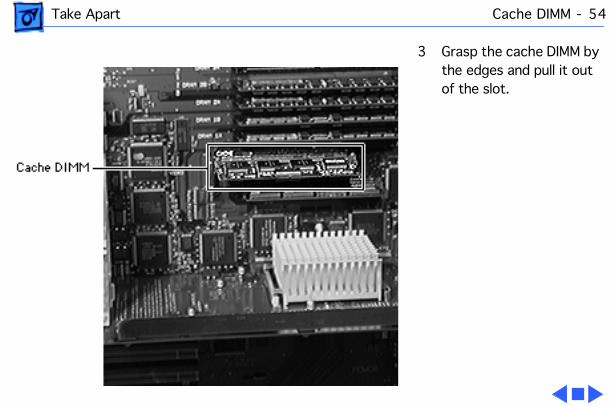
Take Apart Cache DIMM - 54
3 Grasp the cache DIMM by the edges and pull it out of the slot.

Take Apart Logic Board - 55
Logic BoardBefore you begin, disconnect the power cord and remove the following:• Rear drawer• Fan assembly• Processor card
Caution: Review the ESD precautions in Bulletins/Safety.

Take Apart Logic Board - 56
1 Remove the two screws holding the processor card guides.
2 Remove the two processor card guides.
3 Remove the three screws on the logic board.

Take Apart Logic Board - 57
4 Disconnect the fan cable and the rear keyswitch cable (located between the fan cage and the PCI expansion slots).
Note: If you are returning the logic board, be sure to remove the processor card, processor card guides, cache DIMM, DRAM DIMMS, and all other PCI cards except for the ROM SIMM.

Take Apart Logic Board - 58
5 Lift the tabs on the logic board carrier, slide the logic board to the left, and lift the board up and out of the logic board carrier.

Take Apart Mezzanine Interconnect Board - 59
Mezzanine Interconnect BoardBefore you begin, disconnect the power cord, slide the rear drawer out and remove the following:• Rear panel• Top cover
Caution: Review the ESD precautions in Bulletins/Safety.

Take Apart Mezzanine Interconnect Board - 60
1 Disconnect the following from the mezzanine interconnect board:• Mezzanine-to-floppy
drive cable• The 10-inch and 20-
inch mezzanine-to-SCSI backplane SCSI cables
• NMI reset switch cable

Take Apart Mezzanine Interconnect Board - 61
2 Remove the mezzanine interconnect board by pulling it up and away from the standoffs holding it.
3 Rotate the mezzanine interconnect board and disconnect the mezzanine-to-front panel cable.

Take Apart Mezzanine-to-Front Panel Cable - 62
Mezzanine-to-Front Panel CableBefore you begin slide the rear drawer out and remove the following:• Rear panel• Top cover• LCD, speaker, keylock
cable
Caution: Review the ESD precautions in Bulletins/Safety.

Take Apart Mezzanine-to-Front Panel Cable - 63
Remove the two screws that attach the mezzanine-to-front panel cable to the server chassis.

Take Apart Mezzanine-to-SCSI Backplane Cables - 64
Mezzanine-to-SCSI Backplane CablesBefore you begin disconnect the power cord and slide the rear drawer out and remove the following:• Rear panel• Top cover
Caution: Review the ESD precautions in Bulletins/Safety.

Take Apart Mezzanine-to-SCSI Backplane Cables - 65
Disconnect the 10-inch and 20-inch 68-pin mezzanine-to-SCSI backplane cables from the mezzanine interconnect board and from the SCSI backplane board.

Take Apart NMI / Reset Power Interconnect Board - 66
NMI / Reset Power Interconnect Board
Before you begin, disconnect the power cord and slide the rear drawer out and remove the following:• Rear panel• Top cover
Caution:
Review the ESD precautions in Bulletins/Safety.
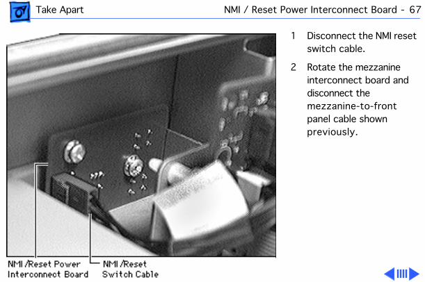
Take Apart NMI / Reset Power Interconnect Board - 67
1 Disconnect the NMI reset switch cable.
2 Rotate the mezzanine interconnect board and disconnect the mezzanine-to-front panel cable shown previously.

Take Apart NMI / Reset Power Interconnect Board - 68
3 Pull the mezzanine interconnect board up to move it out of the way.
4 Remove the two screws holding the NMI/reset power interconnect board and remove the board.

Take Apart Powerplane Interconnect Board (NS 700 Series) - 69
Powerplane Interconnect Board (NS 700 Series)
Before you begin, disconnect the power cord and remove the following:• Rear drawer• Rear panel• Top cover• Left side panel• Left duct• Base door• Power supply

Take Apart Powerplane Interconnect Board (NS 700 Series) - 70
• AC interlock receptacle ground cable
Caution:
Review the ESD precautions in Bulletins/Safety.
Note:
Depress the security tabs on the Power backplane-to-logic board cable connector.
1 Disconnect the power backplane-to-logic board cable from the powerplane interconnect board.

Take Apart Powerplane Interconnect Board (NS 700 Series) - 71
2
Note:
Depress the security tabs on the Power backplane-to-SCSI backplane cable connector.
Disconnect the power backplane-to-SCSI backplane cable from the powerplane interconnect board.

Take Apart Powerplane Interconnect Board (NS 700 Series) - 72
3 Disconnect the ground cables from the main chassis by removing the nut.

Take Apart Powerplane Interconnect Board (NS 700 Series) - 73
4 Lift up and slide the powerplane interconnect board out of the main unit.
Replacement Note:
When replacing the powerplane interconnect board, slide the board into the guides and then drop it down.
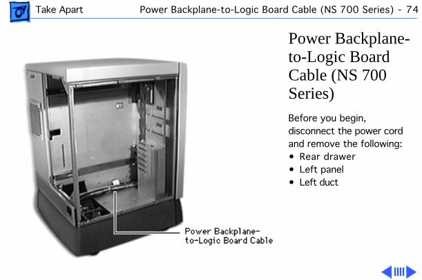
Take Apart Power Backplane-to-Logic Board Cable (NS 700 Series) - 74
Power Backplane-to-Logic Board Cable (NS 700 Series)
Before you begin, disconnect the power cord and remove the following:• Rear drawer• Left panel• Left duct

Take Apart Power Backplane-to-Logic Board Cable (NS 700 Series) - 75
1 Disconnect the power backplane-to-logic board cable from the powerplane interconnect board.

Take Apart Power Backplane-to-Logic Board Cable (NS 700 Series) - 76
2 Detach the power backplane-to-logic board cable from the main chassis by removing the screw.
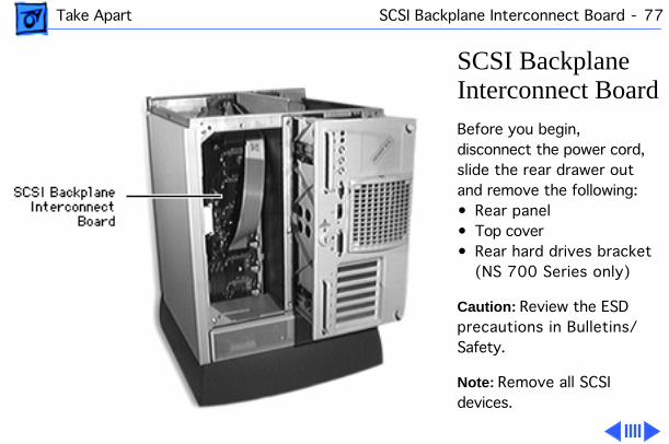
Take Apart SCSI Backplane Interconnect Board - 77
SCSI Backplane Interconnect Board
Before you begin, disconnect the power cord, slide the rear drawer out and remove the following:• Rear panel• Top cover• Rear hard drives bracket
(NS 700 Series only)
Caution:
Review the ESD precautions in Bulletins/Safety.
Note:
Remove all SCSI devices.

Take Apart SCSI Backplane Interconnect Board - 78
1 Disconnect the following from the SCSI backplane interconnect board:• Power backplane-to-
SCSI backplane power cable
• 10-inch and 20-inch 68-pin mezzanine to-SCSI backplane cables
• Rear hard drives SCSI cable (if installed)
• Rear hard drives SCSI ID cable (if installed)
• Rear hard drive power cable (if installed)

Take Apart SCSI Backplane Interconnect Board - 79
2 Remove the two screws located on the SCSI backplane interconnect board.
3 Remove the SCSI backplane interconnect board by sliding it out from the latches towards you.

Take Apart Power Backplane-to-SCSI Backplane Cable - 80
Power Backplane-to-SCSI Backplane Cable
Before you begin, disconnect the power cord, slide the rear drawer out and remove the following:• Rear panel• Top cover• Right side panel
Caution:
Review the ESD precautions in Bulletins/Safety.

Take Apart Power Backplane-to-SCSI Backplane Cable - 81
Remove the power backplane-to-SCSI backplane cable.

Take Apart Battery - 82
Battery
Before you begin, disconnect the power cord.
Caution:
Review the ESD precautions in Bulletins/Safety.

Take Apart Battery - 83
1 With the back of the server facing you, turn the key in the rear drawer lock to the upright (unlocked) position.
2 Loosen the four thumb screws on the rear drawer and slide the rear drawer out.
Note:
Do not detach the rear drawer from the drawer slides.

Take Apart Battery - 84
3 Using a small screwdriver, lift off the battery cover.
4 Carefully remove the battery from its holder.

Take Apart Front Bezel Assembly - 85
Front Bezel Assembly
Before you begin, disconnect the power cord and slide the rear drawer out and remove the following:• Rear panel• Top cover• Base door
Note:
Turn the front lock key to the left (service) position.

Take Apart Front Bezel Assembly - 86
Caution:
Review the ESD precautions in Bulletins/Safety.
1 Slide the front door to the fully open position.

Take Apart Front Bezel Assembly - 87
2 Using a screwdriver or your hands, push in the two snaps at the bottom of the front bezel and pull out to unlatch it.
Note:
This procedure frees the lower side of the front bezel.

Take Apart Front Bezel Assembly - 88
Caution:
Be careful when pulling the front bezel out, as excessive force may damage the bezel.
3 Using a screwdriver, push in the three snaps on the top of the front bezel.

Take Apart Front Bezel Assembly - 89
4 Carefully pull the bezel out and away from the unit.

Take Apart Front Bezel Assembly - 90
5 Disconnect the LCD/ speaker/keylock cable.
6 If you are replacing the front bezel, remove the following from the front panel:•LCD/speaker/keylock
cable• LCD display• Torsion spring• Lock link and lock
shaft
Note:
Be careful when removing the LCD/speaker/ keylock cable because it is very fragile.

Take Apart Front Door - 91
Front Door
Before you begin, disconnect the power cord and remove the following:• Rear panel• Top cover• Base door• Front bezel assembly
Note:
Turn the front lock key to the upright (unlocked) or left (service) position.

Take Apart Front Door - 92
Slide the front door all the way to the right and remove it.

Take Apart Top Shelf - 93
Top Shelf
Before you begin, disconnect the power cord, slide the rear drawer out and remove the following:• Rear panel• Top cover• Base door• Front bezel assembly• Front door
Note:
Turn the front lock key to the upright (unlocked) or left (service) position.
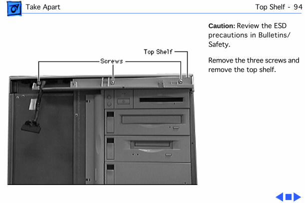
Take Apart Top Shelf - 94
Caution:
Review the ESD precautions in Bulletins/Safety.
Remove the three screws and remove the top shelf.

Take Apart Bottom Shelf - 95
Bottom Shelf
Before you begin, disconnect the power cord, slide the rear drawer out and remove the following:• Rear panel• Top cover• Base door• Front bezel assembly• Front door
Note:
Turn the front lock key to the upright (unlocked) or left (service) position.

Take Apart Bottom Shelf - 96
Caution:
Review the ESD precautions in Bulletins/Safety.
Remove the three screws and remove the bottom shelf.

Take Apart Chassis Shroud - 97
Chassis Shroud
Before you begin, disconnect the power cord and slide the rear drawer out and remove the following:• Rear panel• Top cover• Base door• Front bezel assembly• Front door• Top shelf
Note:
Turn the front lock key to the upright (unlocked) or left (service) position.

Take Apart Chassis Shroud - 98
Caution:
Review the ESD precautions in Bulletins/Safety.
Slide the chassis shroud all the way up and pull it out.

Take Apart Lock Link and Lock Shaft - 99
Lock Link and Lock Shaft
Before you begin, disconnect the power cord and slide the rear drawer out and remove the following:• Rear panel• Top cover• Base door• Front bezel assembly
Note:
Turn the front lock key to the upright (unlocked) position.

Take Apart Lock Link and Lock Shaft - 100
Caution:
Review the ESD precautions in Bulletins/Safety.
1 Remove the lock shaft.
2 Remove the lock link.

Take Apart LCD Display - 101
LCD Display
Before you begin, disconnect the power cord, slide the rear drawer out and remove the following:• Rear panel• Top cover• Base door• Front bezel assembly
Note:
Turn the front lock key to the upright (unlocked) or left (service) position.
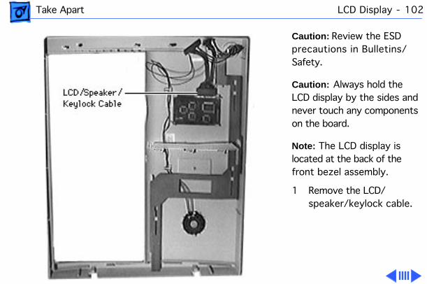
Take Apart LCD Display - 102
Caution:
Review the ESD precautions in Bulletins/Safety.
Caution:
Always hold the LCD display by the sides and never touch any components on the board.
Note:
The LCD display is located at the back of the front bezel assembly.
1 Remove the LCD/ speaker/keylock cable.

Take Apart LCD Display - 103
2 Push one of the two latches holding the LCD display and release the display.
Replacement Note:
When you replace the LCD display, be sure that the display is facing toward the front. Align the display board so that it is inside the two latches, and then slowly push it down until it snaps.

Take Apart LCD/Speaker/ Keylock Cable - 104
LCD/Speaker/ Keylock Cable
Before you begin, disconnect the power cord and slide the rear drawer out and remove the following:• Rear panel• Top cover• Base door• Front bezel assembly
Note:
Turn the front lock key to the upright (unlocked) or left (service) position.

Take Apart LCD/Speaker/ Keylock Cable - 105
Caution:
Review the ESD precautions in Bulletins/Safety.
Caution:
Do not exert force on the snaps as they may break.
1 Push the two snaps away from the speaker and slightly push the speaker up.
2 Disconnect the LCD/ speaker/keylock cable from the LCD display.

Take Apart LCD/Speaker/ Keylock Cable - 106
3 Using pliers remove the metal tab from the front lock.
4 Remove the front lock with the LCD/ speaker/keylock cable.
Replacement Note:
Make sure that the speaker gasket (located between the speaker and the front bezel assembly) is properly seated when you replace the LCD, speaker, keylock cable.

Take Apart Server Name Plate - 107
Server Name Plate
Before you begin, disconnect the power cord and slide the rear drawer out and remove the following:• Rear panel• Top cover• Base door• Front bezel assembly
Note:
Turn the front lock key to the upright (unlocked) or left (service) position.

Take Apart Server Name Plate - 108
Caution:
Review the ESD precautions in Bulletins/Safety.
Press together the two snaps and push the server name plate down and out of the front bezel assembly.

Take Apart CD-ROM Drive - 109
CD-ROM Drive
Before you begin, disconnect the power cord.
Caution:
Review the ESD precautions in Bulletins/Safety.

Take Apart CD-ROM Drive - 110
1 With the front lock key in the upright (unlocked) position, slide the front door to the fully open position.
2 Release the drive drawer clip and slide out the CD-ROM drive.
Note:
Perform the following steps only if you are replacing the SCSI device.

Take Apart CD-ROM Drive - 111
3 Push out the latches holding the narrow drive interconnect board and pull up the board.

Take Apart CD-ROM Drive - 112
4 Remove the following from the CD-ROM drive:• 50-pin SCSI cable• SCSI ID type 3 cable• Power cable

Take Apart CD-ROM Drive - 113
5 Push in the two latches located on the inside of the CD-ROM drive bezel and remove the bezel.

Take Apart CD-ROM Drive - 114
6 Remove the four CD-ROM drive mounting screws and remove the CD-ROM drive from the drive carrier.

Take Apart Floppy Drive - 115
Floppy DriveBefore you begin, disconnect the power cord and slide the rear drawer out and remove the following:• Rear panel• Top cover
Caution: Review the ESD precautions in Bulletins/Safety.

Take Apart Floppy Drive - 116
1 Remove the screw holding the floppy drive bracket.
2 Disconnect the mezzanine-to-floppy drive cable from the floppy drive.

Take Apart Floppy Drive - 117
3 Pull out the floppy drive and bracket.

Take Apart Floppy Drive - 118
4 Remove the four mounting screws and remove the floppy drive from its bracket.

Take Apart Floppy Drive Bezel - 119
Floppy Drive BezelBefore you begin, disconnect the power cord and slide the rear drawer out and remove the following:• Rear panel• Top cover• Right side panel
Caution: Review the ESD precautions in Bulletins/Safety.

Take Apart Floppy Drive Bezel - 120
1 With the front lock key in the upright (unlocked) position, slide the front door to the fully open position.
2 Using a screwdriver, push in the two latches, and pull out the bezel.

Take Apart Tape Drive - 121
Tape DriveBefore you begin, disconnect the power cord.
Caution: Review the ESD precautions in Bulletins/Safety.

Take Apart Tape Drive - 122
1 With the front lock key in the upright (unlocked) position, slide the front door to the fully open position.
2 Release the drive drawer clip and slide out the tape drive.
Note: Perform the following steps only if you are replacing the drive.

Take Apart Tape Drive - 123
3 Push out the latches holding the drive interconnect board and pull up the board.
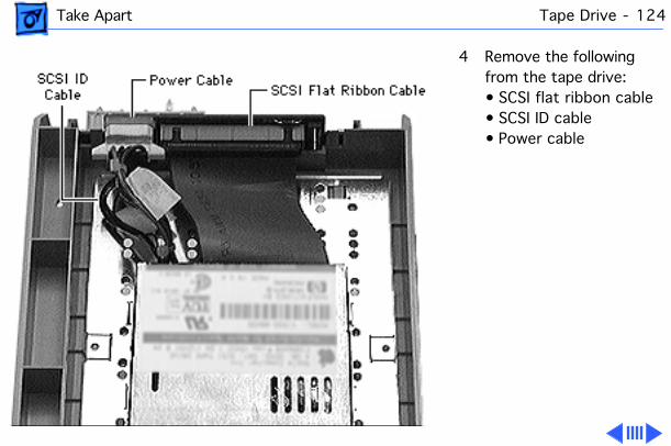
Take Apart Tape Drive - 124
4 Remove the following from the tape drive:• SCSI flat ribbon cable• SCSI ID cable• Power cable

Take Apart Tape Drive - 125
5 Release the two latches located on the inside of the tape drive bezel and remove the bezel.

Take Apart Tape Drive - 126
6 Remove the four drive mounting screws and remove the tape drive from the carrier.

Take Apart Tape Drive - 127
Note: Perform the following two steps only if you are replacing an 8 mm tape drive.
7 Using a T-6 torx driver, remove the two mounting screws and remove the top shield.
8 Replace the two torx screws in the drive.

Take Apart Tape Drive - 128
Note: New drive carriers come with a metal shield, which must be removed to accommodate an 8 mm tape drive.
Perform the following three steps only if you installing an 8 mm tape drive in a new carrier.
9 Using a flat-blade screwdriver, pry up the front corners of the drive carrier shield and release it from the carrier’s two small plastic pegs.

Take Apart Tape Drive - 129
10 Slide the shield forward slightly and disengage the shield’s four metal tabs from the carrier’s plastic tabs.
Note: You may have to use the screwdriver to guide the slots in the shield over the raised screw holes in the carrier.
11 Remove the shield from the carrier.

Take Apart Hard Drive - 130
Hard DriveBefore you begin, disconnect the power cord.
Caution: Review the ESD precautions in Bulletins/Safety.

Take Apart Hard Drive - 131
1 With the front lock key in the upright (unlocked) position, slide the front door to the fully open position.
2 Release the drive drawer clip and slide the hard drive out.
Note: Perform the following steps only if you are replacing the SCSI device.

Take Apart Hard Drive - 132
3 Push out the latches holding the wide drive interconnect board and pull up the board.

Take Apart Hard Drive - 133
4 Remove the following:• 50-pin or 68-pin
SCSI cable• SCSI ID type 1 or type
4 cable• Power cable• Hard drive LED cable

Take Apart Hard Drive - 134
5 Release the two latches located on the inside of the blank bezel and remove the bezel.

Take Apart Hard Drive - 135
6 Remove the four mounting screws and remove the hard drive from the drive carrier.

Take Apart Rail Guides - 136
Rail GuidesBefore you begin, disconnect the power cord.
Caution: Review the ESD precautions in Bulletins/Safety.

Take Apart Rail Guides - 137
1 With the front lock key in the upright (unlocked) position, slide the front door to the fully open position.
2 Remove the required device (CD-ROM drive, DAT tape drive, or hard drive) from the drive bay.
Note: You may need to remove an additional device below the rail guides to access the rail guides.

Take Apart Rail Guides - 138
3 Release the latch on the rail guide and pull out the guide.

Take Apart Wheels - 139
WheelsBefore you begin, disconnect the power cord.
Caution: Review the ESD precautions in Bulletins/Safety.
Caution: When removing the front wheels, be sure the brake lever is in the upright (unlocked) position.
1 Place the server on its back.

Take Apart Wheels - 140
2 Place your finger beneath the wheel and push it up so that the wheel pops out.

Take Apart Brake Lever - 141
Brake LeverBefore you begin, disconnect the power cord and remove the following:• Base door• Wheels (front only)
Caution: Review the ESD precautions in Bulletins/Safety.
1 Place the server on its side.

Take Apart Brake Lever - 142
2 Push the brake lever down and pull it out.

Service Source
K
Upgrades
Network Server 500 and700 Series

Upgrades Third-Party Drives in Front Drive Bays - 1
Third-Party Drives in Front Drive Bays
Note:
Internal SCSI drives from Apple come installed in the drive carrier; third-party drives must be installed in the carrier before you can use them in the server. This procedure explains how to install third-party drives in the front bays of the server .

Upgrades Third-Party Drives in Front Drive Bays - 2
Before you begin, disconnect the power cord.
Caution:
Review the ESD precautions in Bulletins/Safety.
1 With the front lock key in the upright (unlocked) position, slide the front door to the fully open position.
2 Release the drive carrier clip and slide out the drive carrier.

Upgrades Third-Party Drives in Front Drive Bays - 3
Note:
Perform steps 3–6 only if there is an existing drive in the drive carrier.
3 Push out the latches holding the drive interconnect board and pull up the board.

Upgrades Third-Party Drives in Front Drive Bays - 4
4 Remove the following:• 50-pin or 68-pin
SCSI ribbon cable• SCSI ID cable• Power cable• LED cable

Upgrades Third-Party Drives in Front Drive Bays - 5
5 Release the two latches located on the inside of the blank bezel and remove the bezel.

Upgrades Third-Party Drives in Front Drive Bays - 6
6 Remove the four mounting screws and remove the drive from the drive carrier.

Upgrades Third-Party Drives in Front Drive Bays - 7
Note:
Perform steps 7–12 to install the new third-party drive.
7 Attach the following to the third-party drive and the drive intercon-nect board:• 50-pin or 68-pin
SCSI ribbon cable• SCSI ID cable• Power cable• LED cable

Upgrades Third-Party Drives in Front Drive Bays - 8
8 Insert the drive interconnect board into the drive carrier.

Upgrades Third-Party Drives in Front Drive Bays - 9
9 Install the bezel.
Note:
If you are installing a third-party drive that requires a specific bezel (such as a CD-ROM drive, which requires a special slot to accommodate the disc), make sure you install the correct bezel.

Upgrades Third-Party Drives in Front Drive Bays - 10
10 Attach the drive to the drive carrier with the four mounting screws.

Upgrades Third-Party Drives in Front Drive Bays - 11
11 With the drive carrier clip fully released (down), slide the drive carrier into the drive bay until the clip returns to its upright (locked) position.
12 Slide the front door closed, and turn the front lock key to the right (locked) position.

Upgrades Rear Drives (NS 700 Series) - 12
Rear Drives (NS 700 Series)
Note:
This procedure explains how to install drives in the rear drives bracket.
Before you begin, disconnect the power cord.
Caution:
Review the ESD precautions in Bulletins/Safety.

Upgrades Rear Drives (NS 700 Series) - 13
1 With the back of the computer facing you, turn the key in the rear drawer lock to the upright (unlocked) position.
2 Loosen the four thumb screws and slide the rear drawer out.

Upgrades Rear Drives (NS 700 Series) - 14
3 Loosen the thumb screw on the rear panel.

Upgrades Rear Drives (NS 700 Series) - 15
4 Disconnect the fan-to-SCSI-backplane cable and remove the rear panel.

Upgrades Rear Drives (NS 700 Series) - 16
5 Remove the two screws from the rear edge of right side panel.
6 Slide the right side panel off the unit.

Upgrades Rear Drives (NS 700 Series) - 17
7
Note:
If there is an existing drive in the rear drives bracket, remove the bracket.
Remove the screw that attaches the rear drives bracket to the unit and slide the bracket out of the unit.

Upgrades Rear Drives (NS 700 Series) - 18
8 Attach the drive to the drive bracket with the four mounting screws.
Note:
If you are installing two drives, attach the first drive inside the bracket and the second drive on top of the bracket.

Upgrades Rear Drives (NS 700 Series) - 19
Place the rear drives bracket in the server and attach it to the unit with the mounting screw.

Upgrades Rear Drives (NS 700 Series) - 20
9 Attach the following:• Rear drive power
cable• SCSI ribbon cable• SCSI ID cable
Note:
You must terminate the bottom drive in the bracket by attaching the SCSI ID cable and connecting the drive to the last con-nector on the ribbon cable. Or you can set termination by a jumper or switch on the drive. (Check the instructions that came with the drive.) If the bracket contains just one drive,

Upgrades Rear Drives (NS 700 Series) - 21
connect it to the last con-nector on the ribbon cable.
Note:
To set the SCSI ID on third-party drives, you may have to change jumpers. Do not use the SCSI ID cable for third-party drives. For more information, contact your vendor.
10 Replace the right side panel and rear panel.
11 Close the rear drawer, tighten the thumb screws, and turn the key to the right (locked) position.

Upgrades PCI Card - 22
PCI Card
Note:
This procedure explains how to install a PCI card. If you are installing a RAID or FDDI PCI card, see the topics “RAID PCI Card” or “FDDI PCI Card.”
Before you begin, disconnect the power cord.
Caution:
Review the ESD precautions in Bulletins/Safety.

Upgrades PCI Card - 23
1 With the back of the computer facing you, turn the key in the rear drawer lock to the upright (unlocked) position.
2 Loosen the four thumb screws and slide the rear drawer out.

Upgrades PCI Card - 24
3
Caution:
In this step, be careful not to bend the drawer slides.
Using a Phillips screwdriver, unscrew the PCI expansion card cover and remove it.

Upgrades PCI Card - 25
4
Caution:
While inserting the card, be sure to support the drawer with one hand.
Align the card with the expansion slot and press in firmly until the connector is seated.

Upgrades PCI Card - 26
5 Replace the screw that you removed from the expansion card cover.
6 Close the rear drawer, tighten the thumb screws, and turn the key to the right (locked) position.

Upgrades RAID PCI Card - 27
RAID PCI Card
Note:
This procedure explains how to install a RAID PCI card. The card may be installed in the first PCI slot for internal RAID suport and in any PCI slot for external RAID support. Up to four RAID cards may be installed in one unit.
Note:
The card includes a separate battery and SIMM.
Before you begin, discon-nect the power cord and remove the rear drawer and

Upgrades RAID PCI Card - 28
processor card.
Caution:
Review the ESD precautions in Bulletins/Safety.
1
Note:
In this step, be careful not to bend the drawer slides.
Using a Phillips screwdriver, unscrew the PCI expansion card cover and remove it.

Upgrades RAID PCI Card - 29
Note:
As shipped from the factory, the RAID PCI card is fully prepared to use with Network Server internal hard drives. The card is also prepared to work with external arrays only. You may, however, need to adjust termination if you are using the card with both external arrays and internal drives.
The card layout and location of cable connectors and jumpers is shown at left.

Upgrades RAID PCI Card - 30
2 To set termination correctly for mixed internal/external arrays, remove the jumper that corresponds to each channel that has an external array connected to it. If both Channel 0 and Channel 1 are connected to external arrays, remove both jumpers. (Tip: To avoid losing the removed jumper, leave it attached to one pin.)
Note:
You may also need to add a terminator to the

Upgrades RAID PCI Card - 31
last device on each channel.
3
Caution:
While inserting the card, be sure to support the drawer with one hand.
Align the card with the expansion slot and press in firmly until the connector is seated.
Note:
The external connector on the card may interfere with the PCI I/O panel, so you may have to apply some force on the panel while inserting the card.

Upgrades RAID PCI Card - 32
4 Connect the control (AEMI) cable and the two SCSI cables to the logic board.

Upgrades RAID PCI Card - 33
5 Attach the RAID card to the unit using the screw you removed from the expansion card cover.

Upgrades RAID PCI Card - 34
Note:
If you are replacing an existing RAID card, you must remove the SIMM on the original card and trans-fer it to the replacement card.
6 Using a Phillips screw-driver, remove the battery mounting screw.
7 Disconnect the battery from the RAID card and remove the battery.

Upgrades RAID PCI Card - 35
8 Release the two small metal latches on either side of the RAID SIMM.
9 Pull the SIMM up and out of the connector.
10 Install the SIMM on the replacement RAID card.
11 Reinstall the battery on the original RAID card and return it to Apple.

Upgrades Processor Card Upgrade - 36
Processor Card Upgrade
Note:
This procedure explains how to install a processor card upgrade. Perform steps 1–3 if a processor card is already installed in the server.
Before you begin, disconnect the power cord.
Caution:
Review the ESD precautions in Bulletins/Safety.

Upgrades Processor Card Upgrade - 37
1 With the back of the computer facing you, turn the key in the rear drawer lock to the upright (unlocked) position.
2 Loosen the four thumb screws and slide the rear drawer out.

Upgrades Processor Card Upgrade - 38
Caution:
Hold the processor card by the edges, never by the heat sink.
Caution:
Be sure to support the rear drawer with one hand while the other hand pulls the processor card out or puts it back in.
3 Holding the processor card by the edges, pull it out of the logic board connector.

Upgrades Processor Card Upgrade - 39
4 To install the upgraded processor card, position the bottom edges of the card in the processor card guides, and slide the card in until it touches the connector. Then press in on the card so that it is seated firmly.
Caution:
Do not force the card or you may damage it.
5 Close the rear drawer, tighten the thumb screws, and turn the key to the right (locked) position.

Service Source
K
Exploded View
Network Server 500 and700 Series

Exploded View 1
Exploded View
LogicBoard
661-1125
ProcessorCard
661-1126
PowerSupply
661-1131
Floppy Disk Drive661-0121
Top Cover922-2108
Right SidePanel
922-2110
FrontBezel
922-2111
Front Door922-2112
LockLink
922-2117
Lock Shaft922-2116
Wheel922-2121
BrakeLever
922-2122
Left Duct922-2124
Fan Cage922-2127
Logic Bd.Carrier
922-2129
LogicModuleHandle
922-2130
Rear KeySwitch Cable
922-2089
GuideRail
922-2132
DrawerSlide
922-2133
Rear HDBracket922-2137
Floppy DriveBracket922-2138
LCDDisplay922-2077
PowerplaneInterconnect Bd.
922-2078
Lower Rear Plate922-2125
SCSI Bd.922-2080
NMI/Reset-Power Bd.922-2081
Logic Bd.-Power BP Cable
922-2090
A/C InterlockCable
922-2088
FanAssy922-2142
Rear Panel922-2131
Rear DrivesSCSI Cable922-2106
Rear DrivesSCSI ID Cable
922-2107
Rear DrivesPower Cable
922-2105
PowerBP-SCSI-BPCable922-2091
I/O RearPanel
922-2126
ProcessorCard Guides
922-2128
PCI Exp.Cover
922-1628
Fan- L Bd.Cable922-2092
Mez-Floppy Drive Cable922-2094
10"SCSI Cable
922-2095
20"SCSI Cable
922-2096
InterconnectMez Bd.922-2079
NMI ResetSwitchCable922-2086
Fan-SCSIBP Cable922-2093
Floppy DriveBezel922-2143
Top Shelf922-2113
LCD,Speaker,KeylockCable922-2087
Bottom Shelf922-2114
ChassisShroud
922-2115
MainChassis922-2123
Base Door
922-2119
Left Side Panel922-2109

Exploded View 2
InterconnectDrive Bd.922-2082
DAT Tape Drive661-0039
68-PinSCSI Cable
922-2100
DAT DriveBezel
922-2148
CD-ROMDrive Bezel
922-2147
Blank Bezel922-2145
SCSI DevicePower Cable922-2097
50-PinSCSI Cable
922-2101
SCSI DevicePowerCable
922-2097
CD-ROMDrive661-1167
Hard Drive661-0958Wide
Inter:Drive Bd.922-2083
68-PinSCSI Cable922-2100
Hard Drive/LED Cable922-2098
Drive Carrier922-2144
SCSIDevicePowerCable
922-2097
SCSIID Type 2
Cable922-2103
SCSIID Type 3
Cable922-2104
SCSIID Type 1 or 4
Cable922-2102
Recommended

![MULTILAYER CERAMIC CHIP CAPACITORS€¦ · Type: C1005 [0402 inch], C1608 [0603 inch], C2012 [0805 inch], C3216 [1206 inch], C3225 [1210 inch], C4520 [1808 inch], C4532 [1812 inch],](https://img.pdfslide.net/doc/110x75/5f2a18c3f073e37da14b10b6/multilayer-ceramic-chip-capacitors-type-c1005-0402-inch-c1608-0603-inch-c2012.jpg)


![MLCC Commercial grade C series · Type: C0402 [01005 inch], C0603 [0201 inch], C1005 [0402 inch], C1608 [0603 inch], C2012 [0805 inch], C3216 [1206 inch], C3225 [1210 inch], C4532](https://img.pdfslide.net/doc/110x75/5f2a1b6cea53687ca900e2cc/mlcc-commercial-grade-c-series-type-c0402-01005-inch-c0603-0201-inch-c1005.jpg)