7/12/2013
Addendum #3 – New Anderson County Hospital
NEW ANDERSON COUNTY HOSPITAL
ADDENDUM #3
Bids Due: Tuesday, July 16, 2013, 2:00 P.M. CDST
Turner Construction Company 2345 Grand Boulevard, Suite 1000 Kansas City, MO 64108 Telephone: (816) 283-0555 Fax: (816) 283-0558
THIS ADDENDUM IS ISSUED AS PART OF THE CONTRACT DOCUMENTS FOR THIS PROJECT AND AMENDS ONLY THOSE ITEMS SPECIFICALLY DEFINED HEREIN.
In preparing bids, the Bidders shall take into consideration the following items. Information shown herein supersedes requirements issued under previous date. BIDDERS QUESTIONS
1. Design Development Pre-Bid RFI’s – Response
2. Parking Lot Light Pole Layout
3. Supplemental Drawing – HSS Columns and Associated Footings
4. Supplemental Drawing – Colored Concrete
END OF ADDENDUM #3 SUMMARY

Addendum #3 July 12, 2013
1 of 6
New Anderson County Hospital Design Development Pre-Bid RFI’s
Demolition
1. Will it be suitable to backfill basement with removed concrete slabs from building as long as
compaction is met in the top profile per the asphalt paving details or does the whole basement need
to be backfilled with suitable soil? – Assume backfill with concrete/asphalt is not acceptable at this
time. Voluntary alternates for this option will be considered.
Structural Steel
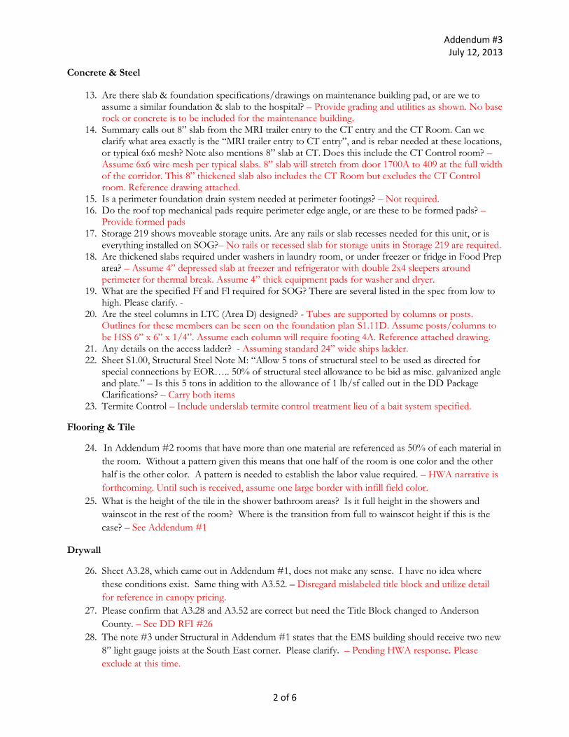
2. How are the HSS tubes supported over the doorways in the long term care wings per typical detail
11/S3.03? – Tubes are supported by columns or posts. Outlines for these members can be seen on
the foundation plan S1.11D. Assume posts/columns to be HSS 6” x 6” x 1/4”.
3. Is tube steel required over door 3100? – Not required.
Site Utilities / Site Work
4. Is relocation of the fiber optic line to be included inside the GMP, or is this being done directly with the Hospital? – Assume this work is NOT included within the GMP.
5. Need a clear site demo plan for utilities showing existing feeds to hospital/EMS building. Will new configuration (water, gas, fiber optic) be able to happen prior to construction and keep everything live? – There is conflicting information between C4.00 and C6.00. Please provide clarification of conflicting site utility information between the two documents. – Assume new utilities are installed per C4.00. As a reference, existing utilities are shown on C6.00.
6. Where does City of Garnett utility work stop/start? Need a clear point of demarcation for each utility. – All new utilities to be performed by site utilities subcontractor.
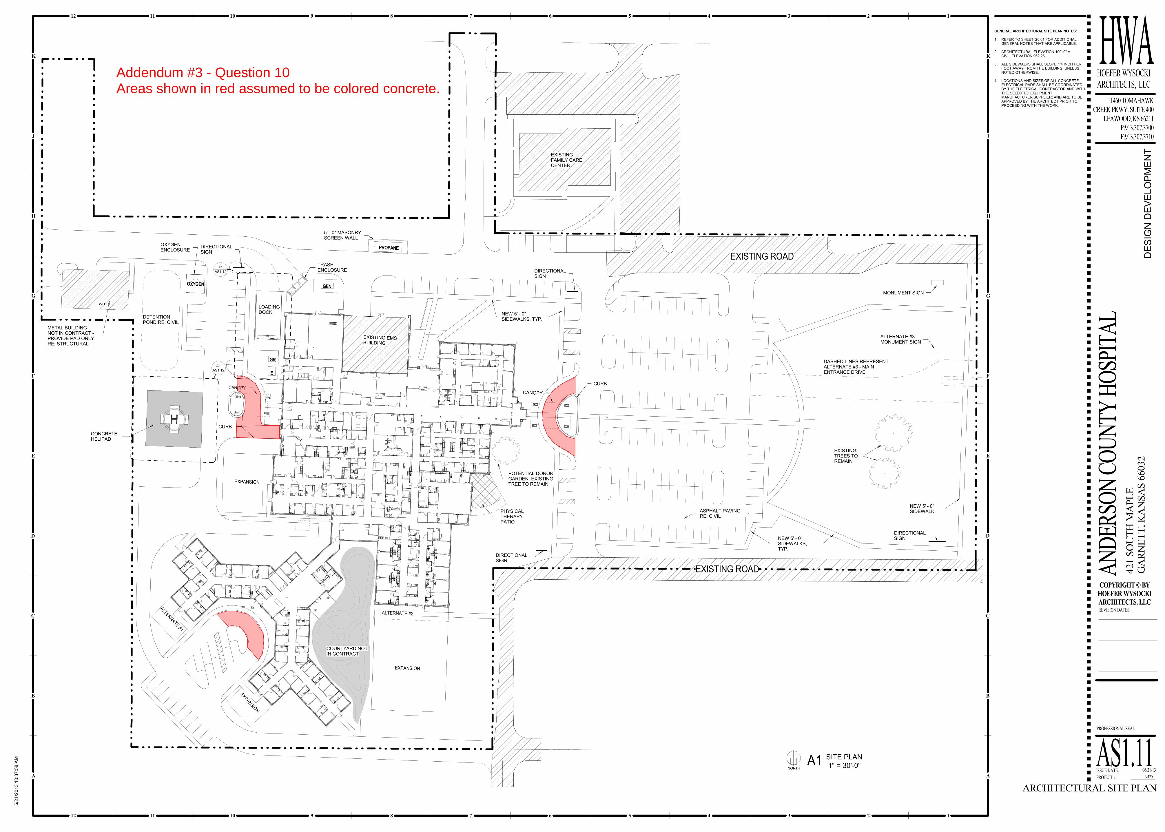
7. AS1.11 shows direction signs. Are concrete pads needed at these locations? – Yes, Assume 2’ x 6’ x 1’
8. Need site electrical package? Do we need to assume an amount of light poles? Per previous notes this quantity was around 18-19 poles. - Light poles addressed on 7/10. Just sign clarification.
9. Are directional signs illuminated, or just sign boards? – The (2) monument signs on Hwy 59 (Maple Street) are to be illuminated. All others are not lit.
10. Are any patios required to be stamped, colored or stained? Assuming regular exterior gray concrete with CJ patterns shown. – No stamped or stained concrete. Colored concrete to be provided per drawing attached.
11. Sheets C10.00 and C11.00 in addendum one indicate the use of KCMMB4K for the concrete paving/sidewalks. As you know KCMMB4K is widely used in the KC Metro area but will be an issue in Garnett, KS. The costs associated with shipping the special aggregates down there and having separate bins will drive the costs way high. We are not sure the ready mix company in Garnett is a KCMMB4K member. Is there an alternate site concrete mix utilizing standard locally available aggregates that would be acceptable? – Assume concrete mix will be amended to allow for local aggregate materials in lieu of KC Metro aggregate
12. No gates shown on the trash enclosure. Is this correct? - Assume trash enclosure does not have gates as show per contract documents
Addendum #3 July 12, 2013
2 of 6
Concrete & Steel
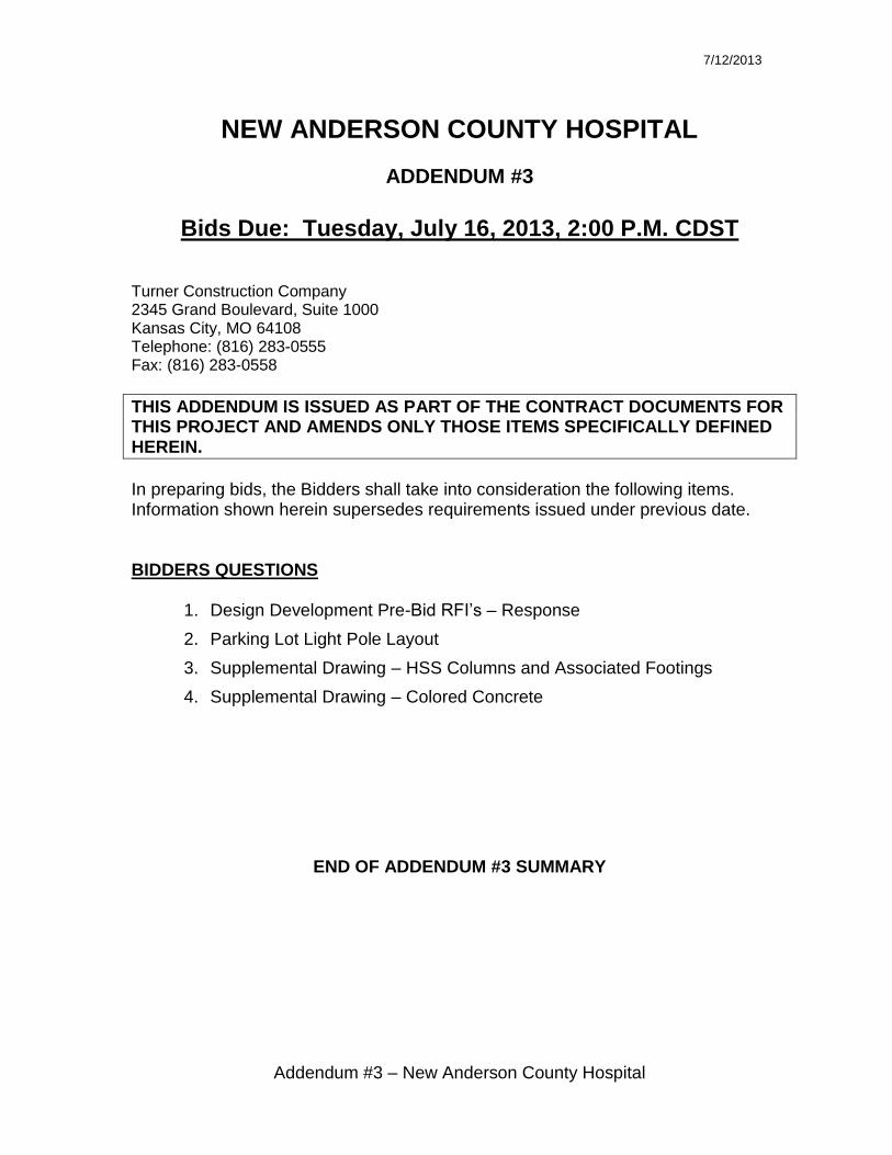
13. Are there slab & foundation specifications/drawings on maintenance building pad, or are we to assume a similar foundation & slab to the hospital? – Provide grading and utilities as shown. No base rock or concrete is to be included for the maintenance building.
14. Summary calls out 8” slab from the MRI trailer entry to the CT entry and the CT Room. Can we clarify what area exactly is the “MRI trailer entry to CT entry”, and is rebar needed at these locations, or typical 6x6 mesh? Note also mentions 8” slab at CT. Does this include the CT Control room? –Assume 6x6 wire mesh per typical slabs. 8” slab will stretch from door 1700A to 409 at the full width of the corridor. This 8” thickened slab also includes the CT Room but excludes the CT Control room. Reference drawing attached.
15. Is a perimeter foundation drain system needed at perimeter footings? – Not required. 16. Do the roof top mechanical pads require perimeter edge angle, or are these to be formed pads? –
Provide formed pads 17. Storage 219 shows moveable storage units. Are any rails or slab recesses needed for this unit, or is
everything installed on SOG?– No rails or recessed slab for storage units in Storage 219 are required. 18. Are thickened slabs required under washers in laundry room, or under freezer or fridge in Food Prep
area? – Assume 4” depressed slab at freezer and refrigerator with double 2x4 sleepers around perimeter for thermal break. Assume 4” thick equipment pads for washer and dryer.
19. What are the specified Ff and Fl required for SOG? There are several listed in the spec from low to high. Please clarify. -
20. Are the steel columns in LTC (Area D) designed? - Tubes are supported by columns or posts. Outlines for these members can be seen on the foundation plan S1.11D. Assume posts/columns to be HSS 6” x 6” x 1/4”. Assume each column will require footing 4A. Reference attached drawing.
21. Any details on the access ladder? - Assuming standard 24” wide ships ladder. 22. Sheet S1.00, Structural Steel Note M: “Allow 5 tons of structural steel to be used as directed for
special connections by EOR….. 50% of structural steel allowance to be bid as misc. galvanized angle and plate.” – Is this 5 tons in addition to the allowance of 1 lb/sf called out in the DD Package Clarifications? – Carry both items
23. Termite Control – Include underslab termite control treatment lieu of a bait system specified.
Flooring & Tile
24. In Addendum #2 rooms that have more than one material are referenced as 50% of each material in
the room. Without a pattern given this means that one half of the room is one color and the other
half is the other color. A pattern is needed to establish the labor value required. – HWA narrative is
forthcoming. Until such is received, assume one large border with infill field color.
25. What is the height of the tile in the shower bathroom areas? Is it full height in the showers and
wainscot in the rest of the room? Where is the transition from full to wainscot height if this is the
case? – See Addendum #1
Drywall
26. Sheet A3.28, which came out in Addendum #1, does not make any sense. I have no idea where
these conditions exist. Same thing with A3.52. – Disregard mislabeled title block and utilize detail
for reference in canopy pricing.
27. Please confirm that A3.28 and A3.52 are correct but need the Title Block changed to Anderson
County. – See DD RFI #26
28. The note #3 under Structural in Addendum #1 states that the EMS building should receive two new
8” light gauge joists at the South East corner. Please clarify. – Pending HWA response. Please
exclude at this time.

Addendum #3 July 12, 2013
3 of 6
29. On RCP, there is a note that states, “All wall cabinets at nurse stations have fascia/soffit that extends
past ceiling.” Is this soffit part of the millwork package? - Yes, we assume this to be part of the
millwork package
30. Are all exterior perimeter soffits and canopies to be EIFS? – Provide under canopy system per note
on A6.11A. Exterior soffits to be “Texture Coat (Stoquik-Gold Soffit System or equivalent) over
gypsum soffit sheathing.
Electrical
31. Will there be another addendum before the bid date that will have a panel schedule and information
on the transformers and generators? - No
32. Many of the wire codes and labels do not match up with the numbers on the key the one line
diagrams. – Contractor to utilize best judgment and experience to provide a complete system. Please
provide assumptions and clarifications.
33. In the technology section about the nurse calls there are two items not listed on the legend, both are
boxed in letters, EQ & PS. – Low voltage to be excluded from the electrical package.
34. The security sheets have 6 items not identified, which are PL, SP, DB, ML, EAC, and SAP. –
Security is included in the Low Voltage package. Exclude from electrical package.
35. There are 7 fixtures which are not identified, these are... on E2.11a- wall light on the north side of
room 202 (Assume SW2), on E2.11B- Wall light on north side of room 202 (Assume SW2), on
E2.11C- the 2x4 in room 606 (Assume TA4), and on E2.11D the 2 wall lights south of the 2100
lobby (Assume SW2) and the 2 2x4 fixtures in room 910 (Assume TD2).
36. There as plan notes [1].[2], [4] that are not explained on the Electrical one line drawings. Can you
tell us what these stand for, or where these notes are explained? – Contractor to utilize best
judgment and experience to provide a complete system. Please provide assumptions and
clarifications.
37. Each Elec one line plan sheet includes a small listing of Transparent Ready Web Enable Devices, but
the listing doesn't give us any text inside the symbols to allow us to determine what is desired on the
drawing. Can we get this provided with the proper symbols? – Contractor to utilize best judgment
and experience to provide a complete system. Please provide assumptions and clarifications.
Mechanical/Plumbing
38. Are we to include in our proposal HVAC requirements for medical equipment? I’ve been scanning
the medical equipment volumes 1&2 for possible items. Haven’t seen any items yet, but it is 1200
pages of stuff. – Yes, include MEP associated with medical equipment per equipment schedule and
SOW.
39. MRI utility requirement. - Assume chiller is by MRI Vendor. Per spec section 011000 - 01.T – Power
pole, sanitary, and water are to be provided for MRI truck parking area. In addition, please provide
data connection at this location. Assumed electrical connection to be (480 – 3-Phase, 200amp).
Provide all water and sanitary sizing assumptions and clarifications.
40. Is a Quench Vent required for the MRI? - Not Required
41. What is required for the Sterilizer steam? domestic water? (Provide electrical, water, and condensate
for sterilizers)

Addendum #3 July 12, 2013
4 of 6
42. Misc refrigeration piping for other equipment – No additional information is available at this time.
Please provide per equipment requirements. If additional information becomes available Turner will
provide to bidders.
43. Provide utility requirements for the mobile MRI – See DD RFI #39 Response
44. SOW #21 – refrigerant monitor (I don’t think this will be required due to air cooled chillers) –
Confirmed, not required.
45. Hoods Provided “Furnish & Install” by Kitchen Equipment Contractor – Duct work connecting to
hoods to be by Mechanical Subcontractor and Fire Suppression (Provided by Fire Suppression
Contractor). Ansul system to be provided by Kitchen Equipment contractor.
46. Does the mechanical need to provided and install refrigeration piping and insulation for freezers /
refrigerator? – Yes
47. Would a Test and Balance firm that is certified by AABC be acceptable? The specifications call for
NEBB certified but do not mention AABC certification. – Assume AABC certification will be
acceptable. Engineer to confirm.
48. Addendum 1, MEP portion, Item 2 makes reference to a hot water unit heater schedule to be shown
on sheet M5.11 The revised sheet M5.11 issued in the addendum does not include a unit heater
schedule. Will that schedule be issued in a future addendum? – No, the unit heater schedule will not
be provided at this time. Assume (1) unit heater per exterior vestibule.
Glass & Glazing
49. Door #103, 104, 105,106, & 315A are indicated on the door schedule to be wood doors in hollow
metal frames. However, the elevations of these doors appear to show them as aluminum sliding
doors. Their hardware set also indicates they are to be automatic sliding doors. Can you please clarify
the material type and specification section(s) that corresponds with these doors? – Assume wood
sliding barn doors with large patterned frit glass lights
50. The Door Schedule calls for Door # 115, 706, 621, 3100, 3000, 2800, 2700, 2000A, & 2000B to be
wood doors. The hardware sets for these doors indicates that they are to be aluminum doors. Please
verify which is correct. Assume these are aluminum doors per the elevation views.
51. The west wall of Waiting #1004 is indicated to have “patterned glass”. However, the elevation of
this area is unclear as to the size of glass that is to be provided. Also, what type of framing is the
glass to go into? Is the “patterned glass” to be assumed to be Glass Type #12 in Section 088000? –
Assume aluminum frame with patterned glass type 12. Scale size per elevation view and provide in
assumptions and clarifications.
52. Door #1300A is shown on the floor plan on Sheet #A1.11B but is not included in the Door
Schedule. Please indicate the door material, frame material, and hardware set that is to be provided at
this opening. – Assume the same as 1500A.
53. There is not a hardware set scheduled for Door #2500. Please clarify what hardware is to be
provided at this door. – Exclude this door. Door to become operable partition per HWA.
54. The Door Schedule indicates that door # 1600, 1600A, 1700B, & 1800 are to be aluminum doors
with aluminum frames. However, based on the application of these doors and the corresponding
hardware sets, I believe the intent maybe for them to be wood or hollow metal doors. Please verify.-
Assume doors to be fire rated wood with hollow metal frames. Vision light to be standard small light
size (approx 6” x 2’-6”).
55. Sheet A1.11C appears to indicate a glazed opening on the north & east walls of Nurse
Station/Supervisor #514. What frame material and glass type is to be provided here? – Provide

Addendum #3 July 12, 2013
5 of 6
aluminum frame and assume glass type 4. Size to be scaled per drawings. Provide assumptions and
clarifications.
56. Paragraph 2.5.A.1 of Section 084113 calls for the aluminum storefront doors to be 1 ¾” thick with
0.125” wall thickness (standard door), 2” thick with 0.188” wall thickness (heavy wall door), and to
be of thermal construction (2” thick with 0.125” wall thickness). Please clarify which of these door
types are to be provided. – All exterior doors to be of Thermal construction. Please provide sizing
per industry best practices and list assumptions and clarifications for interior doors.
57. Item 6.e of the Design Development Package Clarifications calls for switchable privacy glass to be
used at the windows from the surgery scrub sink areas into the operating rooms. The width of this
glass can be derived from the floor plans but there is no elevation within the drawings to determine
the height. Please advise. What type of frame material is to be provided at these openings? The Glass
Type Schedule on Sheet A5.12 indicates that the switchable privacy glass is specified in Section
088870. However, this section was not included in the project manual. Can you please provide it? –
Assume 3’ window height. Specification will not be provided, please utilize industry standard and
best practices to provide assumption and clarification.
58. Item 6.j of the Design Development Package Clarifications states that a “custom ceramic frit glass”
is to be provided at the indicated locations. Which glass type does this correspond with? Is it type
#12? - Yes, assume type 12 is frit glass. This glass type is to be provide at locations per DD RFI
#49. Patterned frit glass is also to be provided on West and North (both sides of fireplace) elevations
of waiting 1004.
59. The drawings do not appear to indicate any locations where the material in Section 081216 is to be
provided. Has the material in this section been eliminated from the project? – Locate at switchable
privacy glass, nurses station, and waiting 1004.
60. Section 088000 and the Glass Type Schedule on Sheet A5.12 both indicate glass types #1 through
14. However, the drawings do not indicate where these glass types are to be provided. Please clarify.-
No clarification will be provided at this time other than those provided in other DD RFI’s. Please
utilize industry standard and best practices for locations of glass types and provide assumptions.
(1,2,3 & 14 to be utilized in exterior storefront systems) (Types 4-13 to be interior) (Fire rated to be
included in all fire rated partitions) (Leaded to be radiology areas)
61. The Door Schedule calls for Door #215 and 1700A to be wood doors but their hardware sets
indicate aluminum doors. Please confirm which is correct. – Assume to be HM with HM frames.
Hardware sets to be adjusted accordingly.
62. Paragraph 1.4.F of Section 084113 requires windborne-debris-impact-resistance performance for the
aluminum storefront systems. Is this truly a requirement of this project? – Yes
Fire Protection
63. The specifications refer to pre-action systems but the locations are not spelled out or shown on the
drawings. – Assume pre-action system in Room 301 – Information Systems and 908 – Data Room.
64. The MEP write up refers to (2) Fire Department Connections (FDC), although the Site Utilities
seems to only refer to one underground entrance. Why would we have 2 FDC’s on 1 entrance?
Although the facility is large enough to require multiple systems, 1 FDC can and should be used for
both. Is there more than one underground entrance to the building? – FDC’s are required at both
entrances (main entrance – long term care and main entrance – hospital) per AHJ.

Addendum #3 July 12, 2013
6 of 6
64.1 Do you know if the fire protection will have a specification for material types? Can you tell us the
scope for the EMS building to remain? – Please review specification 210000. No additional
information to be provided.
Roofing/Sheet Metal
65. Sheet metal coping is addressed in two different spec sections. Section 076200, Sheet Metal Flashing and Trim, at 2.7.B asks for Sheet Metal coping to be fabricated from .050” aluminum with a Smacna detail and FM 1-49 as the reference guide.
Section 077100, Roof Specialties, at 2.5.A, sections 1 through 5, asks for a manufactured sheet metal coping system from extruded aluminum .080” thick “or as required to meet performance requirements” and uses a SPRI ES-1 performance standard. The manufactured coping system is the higher priced of these two systems.
The drawings do not show a manufactured coping cap, they show what appears to be a shop-fabricated coping cap.
Do I have a choice of which spec section to follow?
Is it acceptable to install shop-fabricated coping cap, with the performance standards indicated, per Section 076200? – Specification 076200 can be utilized throughout.

3.6 4 4.3
Y1
R
XA
XB
UU
XC
X1
X2
X3
X4
W18X35
T 114' - 10"
W18X35
T 114' - 10"
B
B
B
B
B
B
B
B
B
BB
B
B
B
B
B
BB
BB
B
B
B
B
B
B
B
B
BB
B
B
B B B B
B
B
B
B
A
A
A
A
A
A
A
A
A
A
A
A
A
A
A
AA
AA
AA
A
A
A
A
A
A
A
A
A
A
A
A
A
A
A
A
A
A
A
A
A
A A
A A
A
A
A
A
800S
162-
54
STUD
S @
16"o
.c.
1200S162-97
1200
S162-
97
1200S
162-9
7
(2)
(2)
(2)
800S162-54 STU
DS @
16"o.c.
800S162-54 STU
DS @
16"o.c.
800S162-54 STU
DS @
16"o.c.
800S
162-5
4 S
TU
DS
@ 1
6"o
.c.
800S
162-5
4 S
TU
DS
@ 1
6"o
.c.
1200S
162-9
7(2
)
800S162-54
STUDS @
16"o.c.
800S
162-
54
STU
DS @
16"
o.c.
800S
162-
54 S
TUDS @
16"
o.c.
800S
162-
54 S
TUDS @
16"
o.c.
1200S162-97
1200S162-97
1200S
162-9
7
(2) (2)
(2)
(2)
(2)(2)
800S162-54
STU
DS @
16"o.c.
800S162-54 STU
DS @
16"o.c.
800S162-54 STU
DS @
16"o.c.
(2)
800S162-54
STUDS @
16"o.c.
800S
162-
54
STU
DS @
16"
o.c.
(2)
(2)
(2)
800S162-54 STUDS @ 16"o.c.
800S162-54 STUDS @ 16"o.c.
800S162-54 STUDS @ 16"o.c.
800S
162-5
4 S
TU
DS
@ 1
6"o
.c.
800S
162-
54 S
TUD
S @ 1
6"o.
c.
800S
162-
54 S
TUDS @
16"
o.c.
800S
162-
54
STUDS @
16"o
.c.
1200S162-97
1200S162-97
1200S
162-9
7
1200S162-97
1200
S162-
97
1200S
162-9
7
HSS10X6X1/4 C
ONT.
HSS10X6X1/4 C
ONT.
HS
S10X6X
1/4
CO
NT.
1000
S200-
54 S
TUDS @
16"
o.c.
9
S3.03
10
S3.03
TYP.
10A
S3.03
TYP. @WINDOW
8
S3.04
12
S3.03
11
S3.03 7
S3.04
TYP.
7A
S3.04
TYP. @DOOR
9
S3.04
10
S3.04
11
S3.04
12
S3.04
13
S3.04
14
S3.04
15
S3.04
1
S3.05
2
S3.05
3
S3.05
4
S3.05
10
S3.03
10A
S3.03
TYP.
TYP. @WINDOW
10
S3.03
10
S3.0310A
S3.03
TYP. @WINDOW
10
S3.03
TYP.
10
S3.03
TYP.
10A
S3.03
TYP. @WINDOW
10
S3.03
TYP.
10A
S3.03
TYP. @WINDOW
10
S3.03
10
S3.03TYP.
10A
S3.03TYP. @WINDOW
7
S3.04
10
S3.03
TYP.
10A
S3.03
TYP. @WINDOW
10
S3.03
TYP.
12
S3.03
11
S3.03
12
S3.03
10
S3.03
TYP.
10A
S3.03
TYP. @WINDOW
10
S3.03
TYP.
12
S3.03
11
S3.03
12
S3.03
10
S3.03
TYP.
10A
S3.03TYP. @WINDOW
10
S3.03
7
S3.047
S3.04
7
S3.04
S2.00
L
RD-2
S1.12D
2
XB.8
XE
X3.9
X3.2
X3.3
X3.4
HSS6X6X
1/4
B 109' - 4"
HSS
12X6X
1/4
B 109
' - 4
"
HSS6X6X
1/4
B 109' - 4"
600S
162-
54 S
TUD
S @ 1
6"o.
c.
HSS
10X6X
1/4
HSS10
X6X1/
4
HSS18
X6X5/
16
T 114
' - 0
"
HSS10
X6X1/
4
T 112
' - 4
"
HSS8X6X
1/4
B 112' - 1 1/2"
HSS8X
6X1/
4
T 113
' - 8
1/2
"
HSS8X
6X1/
4
HSS
10X6X
1/4
T 112
' - 4
"
HSS8X6X
1/4
T 112' - 4"
HSS10X6X
1/4
T 112' - 4"
HSS
10X6X
1/4
T 113
' - 1
0 1/
2"H
SS10
X6X1/
4
T 113
' - 1
0 1/
2"
XD
HSS18
X6X1/
4
B 108
' - 1
0"
A
LEGENDCD-1
RD-1
RD-2
5" NW COMPOSITE SLAB:3.5" CONCRETE ATOP 1.5",22ga COMPOSITE DECK(REINF. SLAB W/ 6x6-6/6 WWF)
1.5", 22ga WIDE RIB ROOF DECK(GALV.) W/ FASTENER/WELDPATTERN TO DEVELOP 300 plfDIAPHRAGM SHEAR
1.5", 24ga WIDE RIB ROOF DECK(GALV.) W/ #12 TEK SCREWS @12"oc @ SUPPORTS
UU
XC
X1X2
9
S3.04
10
S3.04
11
S3.04
13
S3.04
4
S3.05
XB.8
X3.3
HSS10X6X1/4
T 115' - 6"
HS
S10X
6X
1/4
T 1
15' -
6"
HSS10X6X1/4
T 115' - 6"
HS
S10X
6X
1/4
T 1
15' -
6"
PRE-ENGINEER MTLTRUSSES @ 24"o.c.
PR
E-E
NG
INE
ER
MT
LT
RU
SS
ES
@ 2
4"o
.c.
PRE-ENGINEER MTLTRUSSES @ 24"o.c.
PRE-ENGINEER MTLTRUSSES @ 24"o.c.
PRE-ENGINEER MTLTRUSSES @ 24"o.c.
PRE-ENGINEER MTLTRUSSES @ 24"o.c.
ISSUE DATE:
PROJECT #.
PROFESSIONAL SEAL
HWAHOEFER WYSOCKI
ARCHITECTS, LLC
COPYRIGHT © BY
HOEFER WYSOCKI
ARCHITECTS, LLC
K
J
H
G
F
E
D
C
B
A
12 11 10 9 8 7 6 5 4 3 2 1
12 11 10 9 8 7 6 5 4 3 2 1
K
J
H
G
F
E
D
C
B
A
11460 TOMAHAWK
CREEK PKWY. SUITE 400
LEAWOOD, KS 66211
P:913.307.3700
F:913.307.3710
REVISION DATES:
6/2
1/2
013 9
:48:3
5 A
M
ROOF FRAMING
- AREA D
AN
DER
SON
CO
UN
TY H
OSP
ITA
L
06/21/13
94251
421 S
OU
TH
MA
PL
E
GA
RN
ET
T, K
AN
SA
S 6
6032
DE
SIG
N D
EV
ELO
PM
EN
T
S1.12D 1/8" = 1'-0"1 ROOF FRAMING PLAN - AREA D 1/4" = 1'-0"2 HIGH ROOF FRAMING PLAN
Addendum #3 Question 2 & 20Highlighted HSS columns assumed to be 6x6x1/4", assume Type 4A SpreadFootings at each location unless noted otherwise.
36" DECI DUAOUS TREE
48" HACKBER RY
48" HACKB ERRY
WH
GENERAL ARCHITECTURAL SITE PLAN NOTES:
1. REFER TO SHEET G0.01 FOR ADDITIONAL
GENERAL NOTES THAT ARE APPLICABLE.
2. ARCHITECTURAL ELEVATION 100'!0" =
CIVIL ELEVATION 962.25'.
3. ALL SIDEWALKS SHALL SLOPE 1/4 INCH PER
FOOT AWAY FROM THE BUILDING, UNLESS
NOTED OTHERWISE.
4. LOCATIONS AND SIZES OF ALL CONCRETE
ELECTRICAL PADS SHALL BE COORDINATED
BY THE ELECTRICAL CONTRACTOR AND WITH
THE SELECTED EQUIPMENT
MANUFACTURER/SUPPLIER; AND ARE TO BE
APPROVED BY THE ARCHITECT PRIOR TO
PROCEEDING WITH THE WORK.
GEN
PROPANE
E
EXPANSIO
N
EXISTING ROAD
EXISTING ROAD
EXISTING EMSBUILDING
AS1.12
A1
AS1.12
F1
CANOPY
OXYGEN
ALTERNATE #1
ALTERNATE #2
EXPANSION
EXPANSION
GR
CANOPY
EXISTING
FAMILY CARE
CENTER
5' ! 0" MASONRY
SCREEN WALL
TRASH
ENCLOSURE
LOADING
DOCKDETENTION
POND RE: CIVIL
OXYGEN
ENCLOSURE
METAL BUILDING
NOT IN CONTRACT !
PROVIDE PAD ONLY
RE: STRUCTURAL
CONCRETE
HELIPAD
NEW 5' ! 0"
SIDEWALKS, TYP.
NEW 5' ! 0"
SIDEWALKS,
TYP.
ASPHALT PAVING
RE: CIVIL
MONUMENT SIGN
NEW 5' ! 0"
SIDEWALK
DASHED LINES REPRESENT
ALTERNATE #3 ! MAIN
ENTRANCE DRIVE
ALTERNATE #3
MONUMENT SIGN
DIRECTIONAL
SIGN
DIRECTIONAL
SIGN
DIRECTIONAL
SIGN
COURTYARD NOT
IN CONTRACT
PHYSICAL
THERAPY
PATIO
POTENTIAL DONOR
GARDEN. EXISTING
TREE TO REMAIN
EXISTING
TREES TO
REMAIN
CURB
CURB
DIRECTIONAL
SIGN
ISSUE DATE:
PROJECT #.
PROFESSIONAL SEAL
HWAHOEFER WYSOCKI
ARCHITECTS, LLC
COPYRIGHT © BY
HOEFER WYSOCKI
ARCHITECTS, LLC
K
J
H
G
F
E
D
C
B
A
12 11 10 9 8 7 6 5 4 3 2 1
12 11 10 9 8 7 6 5 4 3 2 1
K
J
H
G
F
E
D
C
B
A
11460 TOMAHAWK
CREEK PKWY. SUITE 400
LEAWOOD, KS 66211
P:913.307.3700
F:913.307.3710
REVISION DATES:
6/2
1/2
013 1
0:3
7:5
8 A
M
ARCHITECTURAL SITE PLAN
AN
DER
SON
CO
UN
TY H
OSP
ITA
L
06/21/13
94251
421 S
OU
TH
MA
PL
E
GA
RN
ET
T, K
AN
SA
S 6
6032
DE
SIG
N D
EV
ELO
PM
EN
T
AS1.11 1" = 30'!0"A1 SITE PLAN
NORTH
Addendum #3 Question 10Areas shown in red assumed to be colored concrete.

1 2 2.9 3 3.5 3.6 4 4.3 5
6 6.4
7
9 10 11 12 1313.2 14
Y1
U
T
S
R
Q
P
N
M
L
XA
XB
UU
XC
X1
X2
X3
X4
HSS5X5X
1/4
HSS5X
5X5/16
HSS5X5X
1/4
HSS5X5X
1/4
HSS5X5X
1/4
HSS5X5X
1/4
HSS5X5X
1/4
HSS5X5X
1/4
HSS5X5X
1/4
HSS5X5X
1/4
HSS5X5X
1/4
HSS5X5X
1/4
HSS5X5X
1/4
HSS5X5X
1/4
HSS5X5X
3/8
HSS5X
5X5/16
HSS5X5X
1/4
HSS5X5X
1/4
HSS5X5X
1/4
HSS5X5X
1/4
HSS5X5X
1/4
HSS5X5X
1/4
HSS5X5X
1/4
HSS5X5X
1/4
HSS5X5X
1/4
HSS5X5X
1/4
HSS5X5X
1/4
HSS5X5X
1/4
HSS5X5X
1/4
HSS5X5X
1/4
HSS5X5X
1/4
HSS5X5X
1/4
HSS5X5X
1/4
HSS5X5X
1/4
HSS5X
5X5/16
HSS5X
5X5/16
HSS5X5X
1/4
HSS5X5X
1/4
HSS5X5X
1/4
HSS5X5X
1/4
HSS5X5X
1/4
HSS5X5X
1/4
HSS5X5X
1/4
HSS5X
5X5/16
HSS5X5X
1/4
6.5
15
S3.00
18
S3.00
6
S3.01
TYP.
15
S3.00
TYP.
6
S3.01
6
S3.01
TYP.10
S3.00
TYP.
10
S3.00
17
S3.00
11
S3.00
11
S3.00
9
S3.00
9
S3.00
S3.00
13SIM.
9
S3.00
9
S3.00
14
S3.00
10
S3.00
TYP.
TYP.
TYP.
S3.00
13SIM.
9
S3.00
TYP.
15
S3.00
S3.00
16SIM.
S3.00
12SIM.
11
S3.00
S3.00
13SIM.
9
S3.00TYP.
10
S3.00TYP.
9
S3.00
TYP.
9
S3.00TYP.
17
S3.00
14
S3.00
9
S3.00
TYP.
S3.00
13SIM.
9
S3.00TYP.
17
S3.00
17
S3.00
9
S3.00TYP.
S3.00
13SIM.
10
S3.00
TYP.
8
S3.00TYP.
**
SHEARWALL
*
*
SHEARW
ALL
*
SHEARW
ALL
*
*
*
SH
EA
RW
ALL
*
SHEARW
ALL
***
SH
EA
RW
ALL
6
6
4A 4A
6
6
6
6
4A
6
4A
6
6
6
6
6
4A
4A
4A
4A
6
6
6
4A
6
6
6
4A
6
6
6
6
6
6
4A
6
6
4A
4A
4A
4A
4A
4A
4A
4A
S2.00F
S2.00G
S2.00
H
HSS5X5X
1/4
6
S2.00
J
4" CONCRETE SLAB
ATOP VAPOR BARRIER PER GENERAL NOTES
ATOP 6" GRANULAR CAPILLARY BREAK ATOP
18" LOW VOLUME CHANGE MATERIAL
REINF. SLAB W/ 6x6-6/6 WWF
T/SLAB EL. = 100'-0"
4" CONCRETE SLAB
ATOP VAPOR BARRIER PER GENERAL NOTES
ATOP 6" GRANULAR CAPILLARY BREAK ATOP
18" LOW VOLUME CHANGE MATERIAL
REINF. SLAB W/ 6x6-6/6 WWF
T/SLAB EL. = 100'-0"
XB.8
XE
X3.9
X3.2X3.3
X3.4
4A
4A
4A
4A
4A
4A
4A
4A
4A
4A
XD
ISSUE DATE:
PROJECT #.
PROFESSIONAL SEAL
HWAHOEFER WYSOCKI
ARCHITECTS, LLC
COPYRIGHT © BY
HOEFER WYSOCKI
ARCHITECTS, LLC
K
J
H
G
F
E
D
C
B
A
12 11 10 9 8 7 6 5 4 3 2 1
12 11 10 9 8 7 6 5 4 3 2 1
K
J
H
G
F
E
D
C
B
A
11460 TOMAHAWK
CREEK PKWY. SUITE 400
LEAWOOD, KS 66211
P:913.307.3700
F:913.307.3710
REVISION DATES:
6/2
1/2
013 9
:47:5
9 A
M
FOUNDATION -
AREA C
AN
DER
SON
CO
UN
TY H
OSP
ITA
L
06/21/13
94251
421 S
OU
TH
MA
PL
E
GA
RN
ET
T, K
AN
SA
S 6
6032
DE
SIG
N D
EV
ELO
PM
EN
T
S1.11C 1/8" = 1'-0"1 FOUNDATION PLAN - AREA C Addendum #3 Question 14Area shown to be 8" thick concrete SOG,regular 6x6 Mesh reinforcement.
Recommended