Non-Destructive Evaluation of Polyimide Pipelines Used For
Cryogenic Applications
G Madheswaran1, S Ratheesh
2, Elizabeth John
3
Propellant Engineering Division, Vikram Sarabhai Space Centre,
Thiruvananthapuram – 695022, India
[email protected] / [email protected]
Abstract
Film based conventional X-ray radiography is indispensable for the inspection of launch
vehicle components, particularly composite products like polyimide pipelines to ensure their quality and reliability. The defect detection in film radiography is influenced by many factors
out of which the resolution of the recording medium plays an important role. Defect detection
by X-ray radiography becomes important where no other methodology can be used to assess the
criticality of defects. It is very difficult to assess the nature and severity of defects in cryogenic
sub-systems like polyimide pipelines which are mission critical. Polyimide-Fluoropolymer film is a composite material composed of polyimide with 25 micron thickness and single side
coating of 12.5 micron thick FEP. Polyimide film can be used satisfactorily both at high (up to
473 K) and cryogenic (20 K) temperatures. Polyimide-Fluoropolymer film is wound layer by
layer over the sand mandrel with metallic adapters at both ends and cured to get the pipeline.
De-laminations between the layers, de-bond between the pipeline and metallic adapters, profile variations of the inner wall of pipeline, wrinkles etc are the generally observed defects in these
pipelines. De-laminations with a gap of 0.1 mm can be detected accurately using conventional
radiography. Radiographic inspection facilitates to determine at any location along the pipeline,
the pipe thickness which varies from 1.0 mm to 2.5 mm and the inner diameter, which varies
from 30 mm to 130 mm. Maximum length of the pipeline is 1100 mm. Radiographic inspection of pipelines with different profiles (61 Profiles) is being evaluated and used in all fluid /
propellant lines of Cryogenic Upper Stage. This paper deals with the details of NDT plans at
different levels, criticality of the evaluation and details of study at various stages, like before
and after acceptance test, with and without insulation and for pipelines subjected to deflection
test.
Keywords: composites, polyimide pipeline, conventional radiography, de-laminations, wrinkles,
1.0 Introduction
In today’s world, composite products have become a part of everyday life, finding wide range of applications in automotive and aerospace industry. For launch vehicle applications,
composite materials gain specific advantages over metallic materials mainly due to the greater
specific strength, higher modulus and better thermal properties of these materials. A large
number of critical satellite components like antenna reflectors, solar panel substrates as well as
launch vehicle components like rocket motor cases, pressurant tanks, heat shield, load bearing structures etc. are generally made of composites. Reduction in vehicle mass will increase the
pay-load capability of the vehicle. Composite materials are even found to be advantageous for
cryogenic conditions. A typical example is Polyimide pipeline, identified for use in the
National Seminar & Exhibition on Non-Destructive Evaluation, NDE 2014, Pune, December 4-6, 2014 (NDE-India 2014)
Vol.20 No.6 (June 2015) - The e-Journal of Nondestructive Testing - ISSN 1435-4934www.ndt.net/?id=17863
Cryogenic Upper Stage (CUS) of Launch Vehicles. Polyimide pipeline is a very critical product recently developed for use in the fluid lines of CUS for managing the fuel/propellant in the
stage.
Composite products for use in the launch vehicles call for very high standards of
reliability and confidence level for their acceptance. NDT plays a very crucial role in assessing
the quality of these products because of the very nature of product and also considering the functional criticality of these products in the launch vehicles. The detection of defects in
composite product is very difficult because of the inhomogeneous, anisotropic and layered
nature of the material. Moreover, the defects are often of multiple geometries. Hence, composite
materials in general are to be treated as a different media compared to metals for selection of the
appropriate NDT evaluation method. This often calls for either new technique or modification of the available conventional NDT methods to have faster as well as easier methods suitable for
interpretation and capable of ensuring absence of defects in the products.
Film based conventional radiography is the most reliable non-destructive evaluation
technique used to evaluate the soundness of non metallic materials used in the launch vehicle
systems like propellants, composites, ceramics, rubber products as well as polymeric material. The same was followed for defect detection in polyimide pipelines for cryogenic applications.
The defect detection in polyimide pipelines using the radiography technique is influenced by
many factors of which resolution of the recording medium plays a major role. Methodologies
based on advanced digital radiography are not able to serve the purpose of assessing the nature
and severity of defects in polyimide pipelines.
2.0 Polyimide pipelines
Polyimide pipeline is a novel composite product recently developed for use in the cryo
stage of launch vehicles. The material, polyimide used for making the pipelines is a very
versatile and high strength polymer. The pipelines are employed as fluid lines of the cryogenic stage of rocket engines and are used to carry Liquid Oxygen and Liquid Hydrogen. Advantages
of Polyimide pipelines are their compatibility to cryogenic as well as high temperature
conditions, low specific gravity, low stiffness, capability to withstand thermal shocks and
inherent flexibility. Because of their low stiffness and inherent flexibility to absorb differential
contraction these pipelines acts as thermal compensators in the stage without the need for bellows. The pipelines function as a very critical element of the Pneumo Hydraulic Feed System
(PHFS) and has several important stage functions which include tank chilling, propellant filling
and draining, thermal conditioning and propellant level correction during ground preparation
phase and propellant feed to the thrust chamber and tank.
These pipelines come in different sizes and profiles and are provided with metallic adapters at both the ends. The total requirements of these pipelines for a cryogenic stage are
about 27 numbers and there are about 26 different profiles. The latest version of the C-25
cryogenic stage has 35 pipelines with 35 different profiles. These profiles include pipelines with
straight, single bend and double bends. Diameters of the pipelines vary from 30 mm to 80 mm
and thickness varies from 1.0 mm - 2.0 mm. For C-25 stage, the diameter varies from 50 mm to 130 mm and thickness varies from 1.0 mm - 2.5 mm. Maximum length of the pipeline is about
1100 mm. Since these pipelines carry fuel/propellant in the engine, they are crucial components
for the stage.
2.1 Construction
These pipelines are realized using multilayer winding of narrow strips of polyimide film,
coated with a fluoro polymer and this acts as a single composite material on curing. The
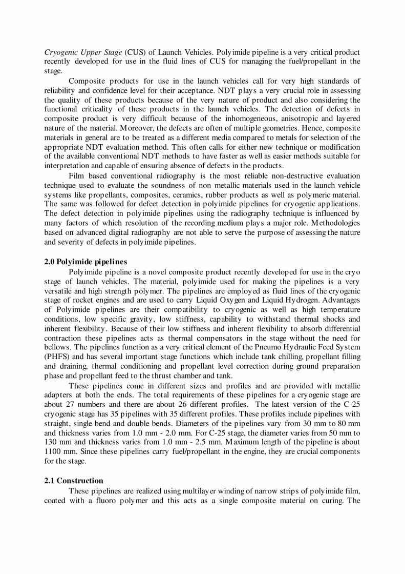
Polyimide-Fluoropolymer film used for realizing the pipeline has polyimide material thickness of 25 micron and has a 12.5 micron coating of FEP flouro polymer. An important advantage of
the film is its heat sealing ability when heated to the melting point of FEP, ie ~ 270°C, which
ensures sealing of multilayer shell of pipeline and it is non-toxic. The pipelines made of this
film are resistant to virtually all gases and liquid hydrogen, oxygen and hydrocarbon fuel like
kerosene.
FEP coated Polyimide films are available in different types such as single side coated
and double side coated. Typical examples of the above material being used in the pipelines are
shown in fig 1.
Fig 1. Single sided & double sided FEP coating on Polyimide
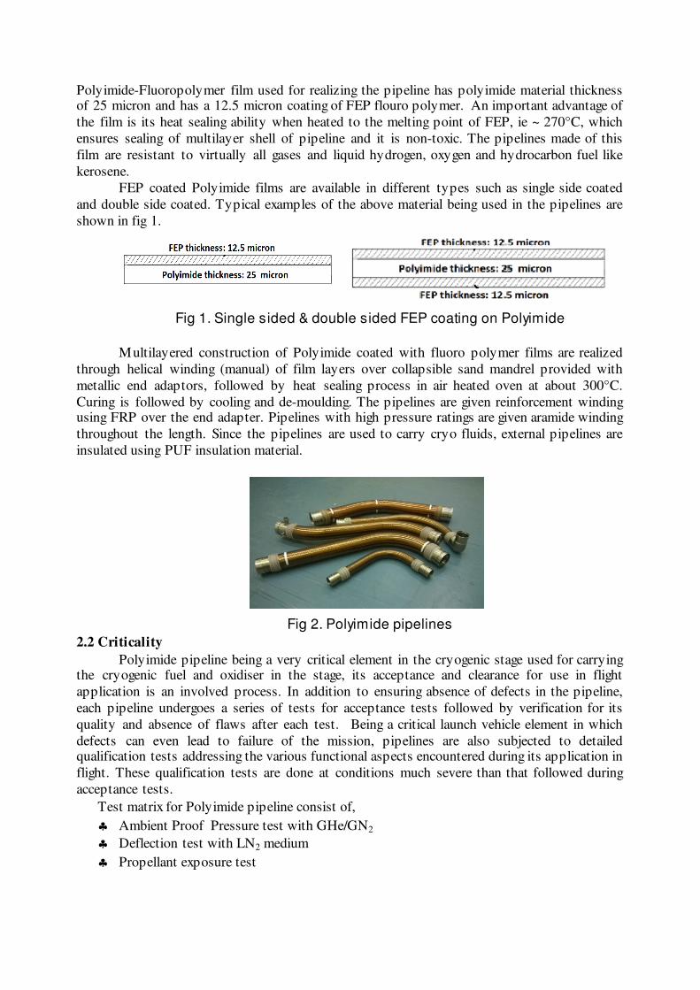
Multilayered construction of Polyimide coated with fluoro polymer films are realized
through helical winding (manual) of film layers over collapsible sand mandrel provided with
metallic end adaptors, followed by heat sealing process in air heated oven at about 300°C.
Curing is followed by cooling and de-moulding. The pipelines are given reinforcement winding using FRP over the end adapter. Pipelines with high pressure ratings are given aramide winding
throughout the length. Since the pipelines are used to carry cryo fluids, external pipelines are
insulated using PUF insulation material.
Fig 2. Polyimide pipelines
2.2 Criticality
Polyimide pipeline being a very critical element in the cryogenic stage used for carrying the cryogenic fuel and oxidiser in the stage, its acceptance and clearance for use in flight
application is an involved process. In addition to ensuring absence of defects in the pipeline,
each pipeline undergoes a series of tests for acceptance tests followed by verification for its
quality and absence of flaws after each test. Being a critical launch vehicle element in which
defects can even lead to failure of the mission, pipelines are also subjected to detailed qualification tests addressing the various functional aspects encountered during its application in
flight. These qualification tests are done at conditions much severe than that followed during
acceptance tests.
Test matrix for Polyimide pipeline consist of,
♣ Ambient Proof Pressure test with GHe/GN2
♣ Deflection test with LN2 medium
♣ Propellant exposure test
♣ Flow test
* Each test will be followed by helium leak check
Non-destructive evaluation, once identified as a method for identifying manufacturing
defects of pipeline is employed after every critical stage of acceptance test and qualification test to rule out appearance of new defects as well as growth of existing defects. Hence it is
important that the technique adopted should be capable of identifying any small deviation in the
physical condition from its initial condition at any location of the pipeline. This becomes
important in the case of profile changes, bends, regions near end adaptors and the criticality
varies from pipe to pipe depending on the test condition.
3.0 NDT Techniques to Assess Polyimide Pipelines
From the above discussion, it is clear that normal NDT techniques developed for metallic products are not suitable for the polyimide pipelines. Based on detailed studies carried
out using different types of polyimide pipelines with different thickness and profiles and during
different stages, suitable NDT techniques as well as procedures were standardized and are being
used for flaw detection in the pipelines and the assessment of its health.
3.1 Visual Inspection
Visual inspection is the very first method of non-destructive testing employed by man
and even today it remains foremost among all the other NDT techniques developed so far, to
detect and evaluate defects in the surface of the products. Visual inspection of both OD and ID
of the pipeline throughout the length gives lot of information useful for interpretation of NDT
observations also.
3.2 Ultrasonic Testing
Like some of the advanced composites, polyimide pipelines are also of low density and
do not lend themselves to nondestructive evaluation with conventional high frequency
ultrasonic inspection methods. Ultrasonic technique is being used as an NDT technique for the
first level evaluation of the polyimide pipelines. The test is being carried out either with a single transducer in pulse-echo mode or with two transducers in through-transmission mode to detect
the defects in the polyimide region of the pipeline. However ultra sonic testing though used is
having several limitations in evaluation of this component.
1. Multilayer de-laminations in the pipelines cannot be detected by this method.
2. Tapered region of the pipeline cannot be inspected.
3. At end adaptor regions (with reinforcement) there are difficulties during the
inspection by through ultrasonic transmission.
4. Aramide wound pipelines (for high pressure applications) cannot be inspected.
5. PUF insulated pipelines (all qualification pipelines) cannot be inspected by
ultrasonic testing.
3.3 Radiographic Testing
Though several advanced techniques are currently available in the NDE field,
conventional radiography technique is the best suited for assess the defects in these pipelines
due to the complexity of the product as explained earlier. The ultrasonic testing method cannot
address the critical requirements due to the above mentioned limitations. Hence film based conventional radiography is the best suited method to assess the soundness of the polyimide
pipelines satisfactorily after every stage.
4.0 Radiographic Inspection
Radiography was introduced basically to inspect the pipelines thickness and to detect
defects like de-laminations between the film layers, de-bond between the polyimide region and
metallic adapters, wrinkles in the adapters end region, cracks and inside details like peel off,
projections, cavities etc at critical regions. Radiographic inspection facilitates determination of
the pipeline thickness at any location along the pipeline which varies from 1.0 mm to 2.5 mm and inner diameter which varies from 30 mm to 130 mm.
4.1 Stages of Radiographic Inspection
Normally all the flight pipelines are subjected to radiography in detail twice: Before
acceptance test and after acceptance test,
But all the pipelines undergoing qualification are radio graphed several times:
♣ Before acceptance,
♣ After acceptance test,
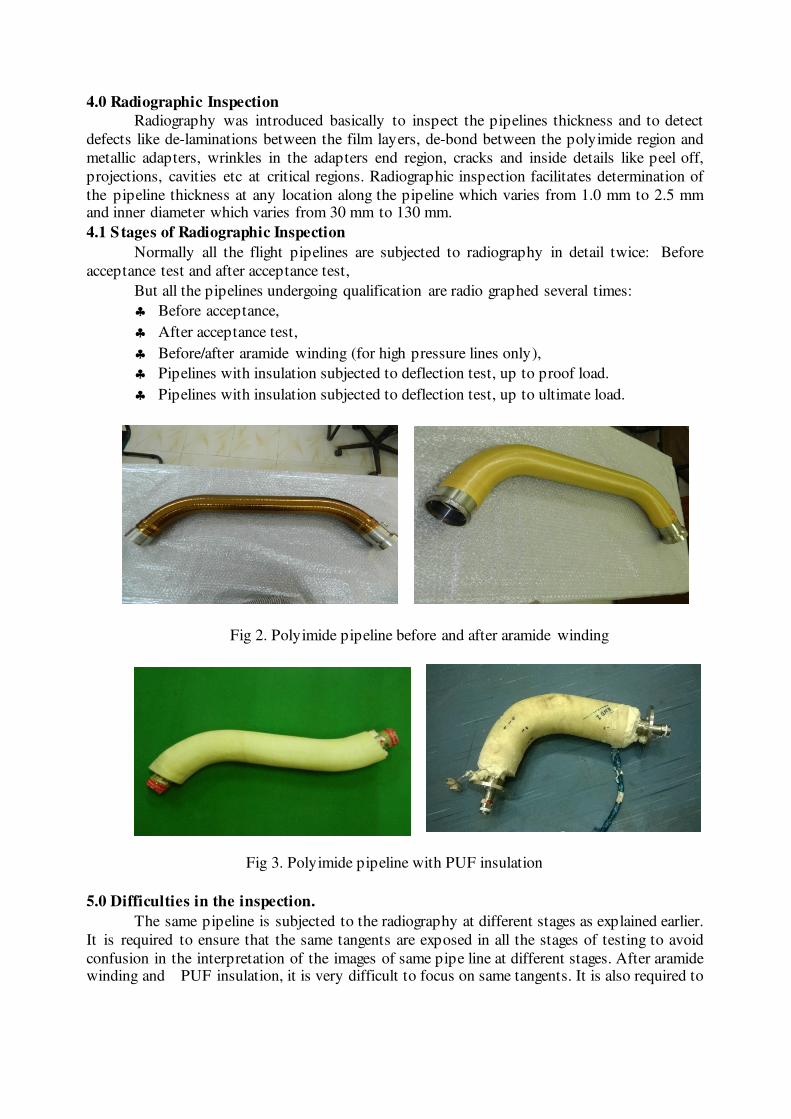
♣ Before/after aramide winding (for high pressure lines only),
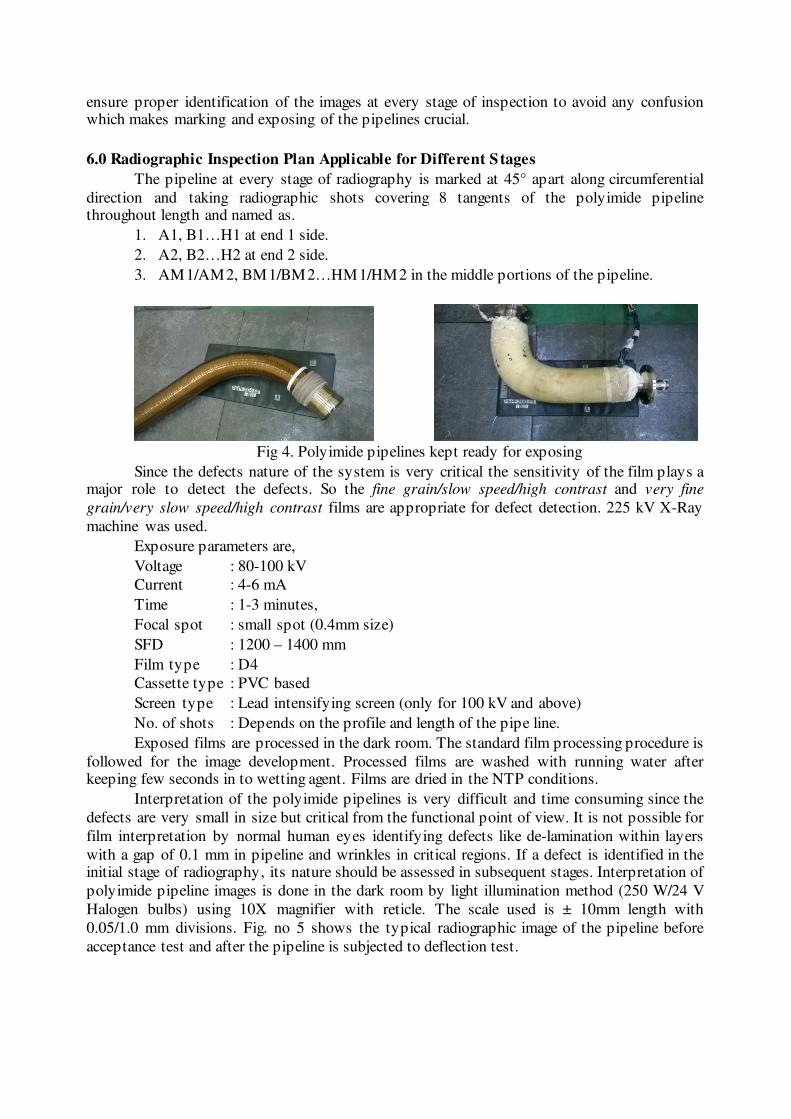
♣ Pipelines with insulation subjected to deflection test, up to proof load.
♣ Pipelines with insulation subjected to deflection test, up to ultimate load.
Fig 2. Polyimide pipeline before and after aramide winding
Fig 3. Polyimide pipeline with PUF insulation
5.0 Difficulties in the inspection.
The same pipeline is subjected to the radiography at different stages as explained earlier.
It is required to ensure that the same tangents are exposed in all the stages of testing to avoid
confusion in the interpretation of the images of same pipe line at different stages. After aramide winding and PUF insulation, it is very difficult to focus on same tangents. It is also required to
ensure proper identification of the images at every stage of inspection to avoid any confusion which makes marking and exposing of the pipelines crucial.
6.0 Radiographic Inspection Plan Applicable for Different Stages
The pipeline at every stage of radiography is marked at 45° apart along circumferential
direction and taking radiographic shots covering 8 tangents of the polyimide pipeline throughout length and named as.
1. A1, B1…H1 at end 1 side.
2. A2, B2…H2 at end 2 side.
3. AM1/AM2, BM1/BM2…HM1/HM2 in the middle portions of the pipeline.
Fig 4. Polyimide pipelines kept ready for exposing
Since the defects nature of the system is very critical the sensitivity of the film plays a major role to detect the defects. So the fine grain/slow speed/high contrast and very fine
grain/very slow speed/high contrast films are appropriate for defect detection. 225 kV X-Ray
machine was used.
Exposure parameters are,
Voltage : 80-100 kV
Current : 4-6 mA
Time : 1-3 minutes,
Focal spot : small spot (0.4mm size)
SFD : 1200 – 1400 mm
Film type : D4
Cassette type : PVC based
Screen type : Lead intensifying screen (only for 100 kV and above)
No. of shots : Depends on the profile and length of the pipe line.
Exposed films are processed in the dark room. The standard film processing procedure is
followed for the image development. Processed films are washed with running water after keeping few seconds in to wetting agent. Films are dried in the NTP conditions.
Interpretation of the polyimide pipelines is very difficult and time consuming since the
defects are very small in size but critical from the functional point of view. It is not possible for
film interpretation by normal human eyes identifying defects like de-lamination within layers
with a gap of 0.1 mm in pipeline and wrinkles in critical regions. If a defect is identified in the initial stage of radiography, its nature should be assessed in subsequent stages. Interpretation of
polyimide pipeline images is done in the dark room by light illumination method (250 W/24 V
Halogen bulbs) using 10X magnifier with reticle. The scale used is ± 10mm length with
0.05/1.0 mm divisions. Fig. no 5 shows the typical radiographic image of the pipeline before
acceptance test and after the pipeline is subjected to deflection test.
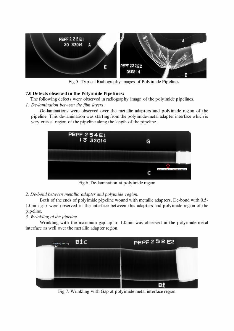
Fig 5. Typical Radiography images of Polyimide Pipelines
7.0 Defects observed in the Polyimide Pipelines:
The following defects were observed in radiography image of the polyimide pipelines,
1. De-lamination between the film layers.
De-laminations were observed over the metallic adapters and polyimide region of the
pipeline. This de-lamination was starting from the polyimide-metal adapter interface which is
very critical region of the pipeline along the length of the pipeline.
Fig 6. De-lamination at polyimide region
2. De-bond between metallic adapter and polyimide region.
Both of the ends of polyimide pipeline wound with metallic adapters. De-bond with 0.5-
1.0mm gap were observed in the interface between this adapters and polyimide region of the
pipeline.
3. Wrinkling of the pipeline
Wrinkling with the maximum gap up to 1.0mm was observed in the polyimide-metal
interface as well over the metallic adapter region.
Fig 7. Wrinkling with Gap at polyimide metal interface region

4. Nature of the inner side of the pipeline. Peel off of the inner most layers of the pipeline, projection and depression on the inner
side of the pipelines and undulation in the inner side of the pipeline were observed.
8.0 Other Possible Defects in the Polyimide Pipelines:
1. Crack in the polyimide region.
Crack across the thickness of the pipeline may occur at polyimide-metal interface of the
pipeline.
2. Inclusions in the polyimide regions.
High density material like cured resin particles and foreign particles may be present in
the polyimide region of the pipeline
9.0 Typical radiographic observations of the polyimide pipeline
Radiographic observations of a polyimide pipeline at end 1 is given below,
Line/
Tangent
Size Distance
from ID
Distance from the
Polyimide end 1
Length of
the de-lamination
over the adaptor
Remarks
Length Max. Gap
A 15 0.1 0.3-1.5 13 15 M 4 layers --
B 6 max. 0.5 X 2.0 0.1-2.0 22 6 M 3 layers at tapered region
D 5 max. 0.1 0.3-1.0 13 5 M 3 layers --
24 0.1 0.8 37 -- -- polyimide region
F 5 max. 1.0 X 2.0 0.8-1.5 25 5 M 2 layers at corner no 2
1. De-bond of 3 mm L X 0.5 mm W is observed in the tangent A & H at 24 mm away from the polyimide
end.
2. Profile variation of 15 mm length is observed close to inside end of the metallic adapter end 1.
(Wall thickness of pipeline varies from 2.5 to 3.5 mm)
3. Wrinkling of polyimide tape with minor de-laminations (≤1mm L X 0.1mm Gap) in multiple layers
observed close to inside end of the metallic adaptor in the tangents A, G & H of end 1 and all the tangents of end 2 (except E).
Max. Size: 13 mm observed at tangent G of end 1.
Max. Size: 6 mm observed at tangents B & C of end 2.
4. Wall thickness varies from 2.8 to 4.2 mm at bend location.
All dimensions are in mm
10.0 Conclusion
The defect detection using the film radiography in the polyimide region and metallic adapters region was successfully implemented for the acceptance and clearance of polyimide
pipeline, the new composite product developed for flight application in the cryogenic stage.
This has enabled the project to induct the indigenously realized pipeline in the cryo stage of our
launch vehicles. NDT inspection and film interpretation was satisfactorily carried out during all
stages of pipeline from realization to qualification till the end use in flight. Total 61 different pipeline profiles were radiographed and qualified for use.
******************************
Recommended
![CRYO-COOLING: why and how? · 2019. 12. 2. · Radiation damage. –Optimising cryoprotection. ... polyimide film. MiTeGen [Thorne et al (2003), JAPC 36, 1455.] Rayon loops Hampton](https://img.pdfslide.net/doc/110x75/60e12d61fc199e647913a87e/cryo-cooling-why-and-how-2019-12-2-radiation-damage-aoptimising-cryoprotection.jpg)