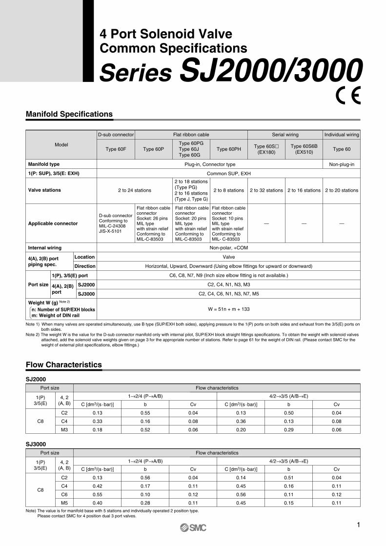
Manifold Specifications
4 Port Solenoid Valve Common Specifications
Note 1) When many valves are operated simultaneously, use B type (SUP/EXH both sides), applying pressure to the 1(P) ports on both sides and exhaust from the 3/5(E) ports on both sides.
Note 2) The weight W is the value for the D-sub connector manifold only with internal pilot, SUP/EXH block straight fittings specifications. To obtain the weight with solenoid valves attached, add the solenoid valve weights given on page 3 for the appropriate number of stations. Refer to page 61 for the weight of DIN rail. (Please contact SMC for the weight of external pilot specifications, elbow fittings.)
Flow Characteristics
SJ2000Flow characteristicsPort size
4/2→3/5 (A/B→E)1→2/4 (P→A/B)
C [dm3/(s·bar)]
0.13
0.33
0.18
b
0.55
0.16
0.52
Cv
0.04
0.08
0.06
C [dm3/(s·bar)]
0.13
0.36
0.20
b
0.50
0.13
0.29
Cv
0.04
0.08
0.06
C8
C2
C4
M3
1(P) 3/5(E)
4, 2 (A, B)
SJ3000Flow characteristicsPort size
4/2→3/5 (A/B→E)1→2/4 (P→A/B)
C [dm3/(s·bar)]
0.13
0.42
0.55
0.40
b
0.56
0.17
0.10
0.28
Cv
0.04
0.11
0.12
0.11
C [dm3/(s·bar)]
0.14
0.45
0.56
0.45
b
0.51
0.16
0.11
0.15
Cv
0.04
0.11
0.12
0.11
C8
C2
C4
C6
M5
1(P) 3/5(E)
4, 2 (A, B)
Note) The value is for manifold base with 5 stations and individually operated 2 position type.Please contact SMC for 4 position dual 3 port valves.
Series SJ2000/3000
Model
D-sub connector
Common SUP, EXH
Plug-in, Connector type Non-plug-in
Non-polar, +COM
Valve
Horizontal, Upward, Downward (Using elbow fittings for upward or downward)
C6, C8, N7, N9 (Inch size elbow fitting is not available.)
C2, C4, N1, N3, M3
C2, C4, C6, N1, N3, N7, M5
W = 51n + m + 133
2 to 24 stations
D-sub connector Conforming to MIL-C-24308 JIS-X-5101
Flat ribbon cable connector Socket: 26 pins MIL type with strain relief Conforming to MIL-C-83503
Flat ribbon cable connector Socket: 20 pins MIL type with strain relief Conforming to MIL-C-83503
Flat ribbon cable connector Socket: 10 pins MIL type with strain relief Conforming to MIL- C-83503
— — —
2 to 18 stations (Type PG) 2 to 16 stations (Type J, Type G)
2 to 8 stations 2 to 32 stations 2 to 16 stations 2 to 20 stations
Type 60PType 60FType 60PG Type 60J Type 60G
Type 60PH Type 60Sl(EX180)
Type 60S6B (EX510)
Type 60
Flat ribbon cable Serial wiring Individual wiring
Applicable connector
Valve stations
Internal wiring
Port size
Weight W (g) Note 2)
4(A), 2(B) port piping spec.
Location
Direction
SJ2000
SJ3000
1(P), 3/5(E) port
4(A), 2(B) port
Manifold type
1(P: SUP), 3/5(E: EXH)
n: Number of SUP/EXH blocks m: Weight of DIN rail
1
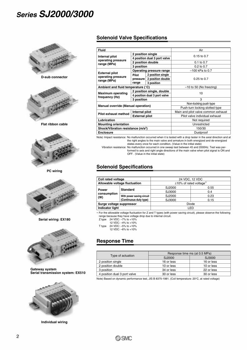
Solenoid Valve Specifications
Note)Impact resistance: No malfunction occurred when it is tested with a drop tester in the axial direction and at the right angles to the main valve and armature in both energized and de-energized states every once for each condition. (Value in the initial state)
Vibration resistance: No malfunction occurred in one sweep test between 45 and 2000Hz. Test was per-formed to axis and right angle directions of the main valve when pilot signal is ON and OFF. (Value in the initial state)
Fluid
Ambient and fluid temperature (°C)
Maximum operating frequency (Hz)
Manual override (Manual operation)
Pilot exhaust method Lubrication Mounting orientation Shock/Vibration resistance (m/s2)Enclosure
Internal pilot operating pressure range (MPa)
External pilot operating pressure range (MPa)
Air
0.15 to 0.7
0.1 to 0.7 0.2 to 0.7
–100 kPa to 0.7
0.25 to 0.7
–10 to 50 (No freezing)
10
3Non-locking push type
Push-turn locking slotted type Main and pilot valve common exhaust
Pilot valve individual exhaust Not required Unrestricted
150/30 Dustproof
2 position single 4 position dual 3 port valve 2 position double 3 position Operating pressure range
2 position single 2 position double 3 position
2 position single, double 4 position dual 3 port valve 3 position
Internal pilot External pilot
D-sub connector
Flat ribbon cable
PC wiring
Serial wiring: EX180
Gateway system Serial transmission system: EX510
Individual wiring
Note) Based on dynamic performance test, JIS B 8375-1981. (Coil temperature: 20°C, at rated voltage)
Response Time
Type of actuationResponse time ms (at 0.5 MPa)
SJ2000 SJ30002 position single 2 position double 3 position 4 position dual 3 port valve
16 or less 10 or less 34 or less 30 or less
16 or less 10 or less 22 or less 30 or less
Coil rated voltage Allowable voltage fluctuation
Power consumption (W)
Surge voltage suppressor Indicator light
Standard
With power saving circuit (Continuous duty type)
24 VDC, 12 VDC ±10% of rated voltage∗
SJ2000 SJ3000 SJ2000 SJ3000
Diode LED
0.55 0.4 0.23 0.15
Solenoid Specifications
Pilot pressure range
∗ For the allowable voltage fluctuation for Z and T types (with power saving circuit), please observe the following range because they have voltage drop due to internal circuit.Z type 24 VDC: –7% to +10%
12 VDC: –4% to +10%T type 24 VDC: –5% to +10%
12 VDC: –6% to +10%
2
Series SJ2000/3000
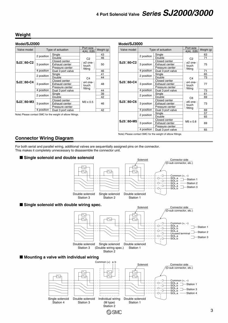
Connector Wiring Diagram
For both serial and parallel wiring, additional valves are sequentially assigned pins on the connector. This makes it completely unnecessary to disassemble the connector unit.
M Mounting a valve with individual wiring
M Single solenoid with double wiring spec.
M Single solenoid and double solenoid
Individual wiring (M type) Station 2
Single solenoid Station 4
Double solenoid Station 3
Double solenoid Station 1
SOL.aSOL.bSOL.aSOL.bSOL.a
Station 3Station 4
Station 1
baCommon (+)Connector side
(D-sub connector, etc.)Solenoid
Common (+, –)
Double solenoid Station 3
Single solenoid (Double wiring spec.)
Station 2
Double solenoid Station 1
SOL.bSOL.a
SOL.aUnused terminal
SOL.aSOL.b
Station 3
Station 2
Station 1Common (+, –)
Connector side (D-sub connector, etc.)
Solenoid
Double solenoid Station 3
Single solenoid Station 2
Double solenoid Station 1
Station 3Station 2Station 1
Connector side (D-sub connector, etc.)
Solenoid
SOL.bSOL.aSOL.aSOL.bSOL.aCommon (+, –)
Weight
Note) Please contact SMC for the weight of elbow fittings.
Single Double Closed center Exhaust center Pressure center Dual 3 port valve Single Double Closed center Exhaust center Pressure center Dual 3 port valve Single Double Closed center Exhaust center Pressure center Dual 3 port valve Single Double Closed center Exhaust center Pressure center Dual 3 port valve
2 position
3 position 4 position
2 position
3 position 4 position
2 position
3 position 4 position
2 position
3 position 4 position
63 71 75
716573
77
73 61 69
73 6957 65 69
65
SJ3l60-C2
SJ3l60-C4
SJ3l60-C6
SJ3l60-M5
Port size 4(A), 2(B)Type of actuationValve model Weight (g)
M5 x 0.8
Model/SJ3000
Note) Please contact SMC for the weight of elbow fittings.
Single Double Closed center Exhaust center Pressure center Dual 3 port valve Single Double Closed center Exhaust center Pressure center Dual 3 port valve Single Double Closed center Exhaust center Pressure center Dual 3 port valve
43 46 50
464144
48
44 39 42
46 42
2 position
3 position 4 position
2 position
3 position 4 position
2 position
3 position 4 position
SJ2l60-C2
SJ2l60-C4
SJ2l60-M3
Port size 4(A), 2(B)Type of actuationValve model Weight (g)
C2
C4
C6
ø2 one- touch fitting
ø4 one- touch fitting
ø6 one- touch fitting
C2
C4
ø2 one- touch fitting
ø4 one- touch fitting
M3 x 0.5
Model/SJ2000
3
4 Port Solenoid Valve Series SJ2000/3000
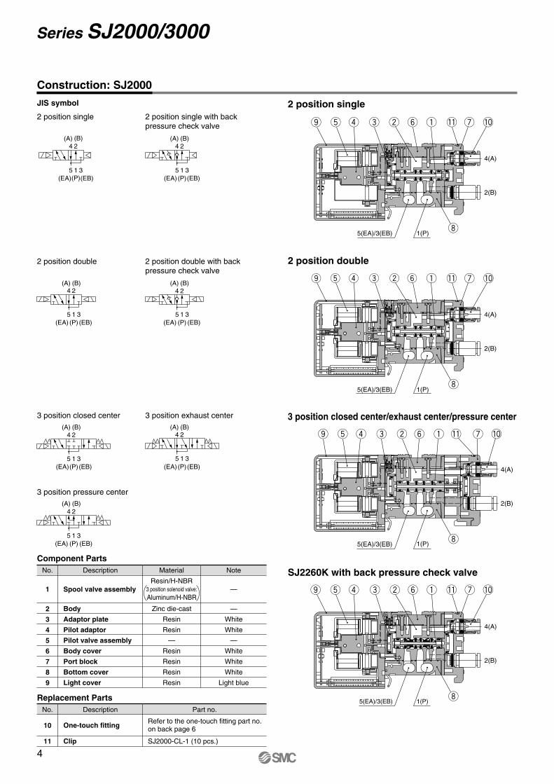
Construction: SJ2000
JIS symbol
2 position single 2 position single with back pressure check valve
2 position double with back pressure check valve
2 position single
2 position double 2 position double
3 position closed center 3 position closed center/exhaust center/pressure center
SJ2260K with back pressure check valve
10
11
DescriptionNo. Part no.
Replacement Parts
One-touch fitting
Clip
Refer to the one-touch fitting part no. on back page 6
2
3
4
5
6
7
8
9
DescriptionNo. Material Note
Component Parts
Body
Adaptor plate
Pilot adaptor
Pilot valve assembly
Body cover
Port block
Bottom cover
Light cover
Zinc die-cast
Resin
Resin
—
Resin
Resin
Resin
Resin
—
White
White
—
White
White
White
Light blue
1 Spool valve assemblyResin/H-NBR
—
SJ2000-CL-1 (10 pcs.)
35 1(EB)(P)(EA)
24(A) (B)
5(EA)/3(EB) 1(P)
5(EA)/3(EB) 1(P)
5(EA)/3(EB) 1(P)
5(EA)/3(EB) 1(P)
o t r e w y
i
o
i
i
t r e w y q !1 u !0
q !1 u !0
!0u
i
!1qywerto
!0u!1qywerto
35 1(EB)(P)(EA)
24(B)(A)
35 1
24
(EB)(P)(EA)
(B)(A)
35 1(EB)(P)(EA)
35 1(EB)(P)(EA)
24(B)(A)
24(B)(A)
3 position pressure center
35 1(EB)(P)(EA)
4(A)
2(B)
3 position exhaust center
35 1(P)(EA)
24(B)(A)
(EB)
3 position solenoid valve: Aluminum/H-NBR
4(A)
2(B)
4(A)
2(B)
4(A)
2(B)
4(A)
2(B)
4
Series SJ2000/3000
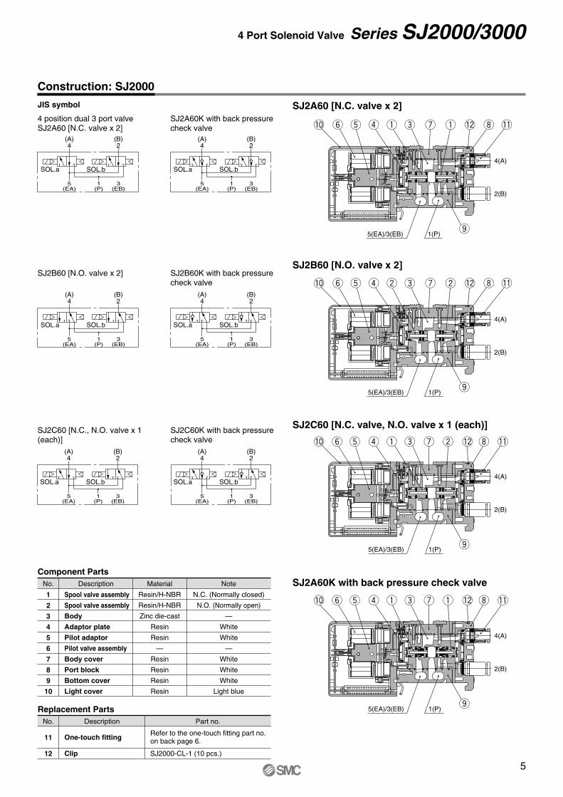
SJ2A60 [N.C. valve x 2]
SJ2B60 [N.O. valve x 2] SJ2B60K with back pressure check valve
SJ2B60 [N.O. valve x 2]
SJ2C60 [N.C., N.O. valve x 1 (each)]
SJ2C60K with back pressure check valve
SJ2C60 [N.C. valve, N.O. valve x 1 (each)]
SJ2A60K with back pressure check valve
4 position dual 3 port valve SJ2A60 [N.C. valve x 2]
JIS symbol
SJ2A60K with back pressure check valve
11
12
DescriptionNo. Part no.
Replacement Parts
One-touch fitting
Clip
Refer to the one-touch fitting part no. on back page 6.
1
2
3
4
5
6
7
8
9
10
DescriptionNo. Material Note
Component Parts
Spool valve assembly
Spool valve assembly
Body
Adaptor plate
Pilot adaptor
Pilot valve assembly
Body cover
Port block
Bottom cover
Light cover
Resin/H-NBR
Resin/H-NBR
Zinc die-cast
Resin
Resin
—
Resin
Resin
Resin
Resin
N.C. (Normally closed)
N.O. (Normally open)
—
White
White
—
White
White
White
Light blue
SJ2000-CL-1 (10 pcs.)
!0 y t r q e u q !2 i !1
!0 y t r w e u w !2 i !1
!0 y t r q e u w !2 i !1
o
o
5(EA)/3(EB) 1(P)
5(EA)/3(EB) 1(P)
o5(EA)/3(EB) 1(P)
!0 y t r q e u q !2 i !1
5(EA)/3(EB) 1(P)o
(A) 4
5(EA)
1(P)
3(EB)
(B) 2
SOL.a SOL.b
(A) 4
5(EA)
1(P)
3(EB)
(B) 2
SOL.a SOL.b
SOL.b
(A) 4
5(EA)
1(P)
3(EB)
(B) 2
SOL.a SOL.b
(A) 4
5(EA)
1(P)
3(EB)
(B) 2
SOL.a
(A) 4
5(EA)
1(P)
3(EB)
(B) 2
SOL.a SOL.b
(A) 4
5(EA)
1(P)
3(EB)
(B) 2
SOL.a SOL.b
4(A)
2(B)
4(A)
2(B)
4(A)
2(B)
4(A)
2(B)
Construction: SJ2000
5
4 Port Solenoid Valve Series SJ2000/3000
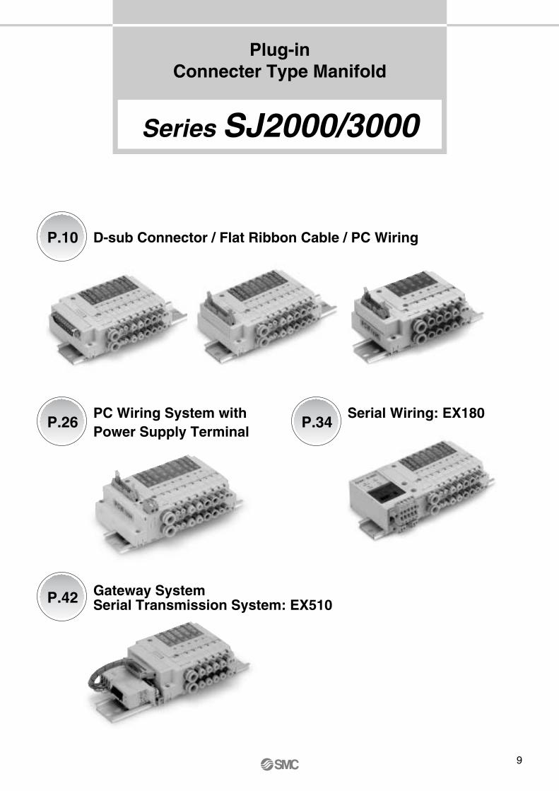
Plug-in Connecter Type Manifold
D-sub Connector / Flat Ribbon Cable / PC WiringP.10
P.26
P.42
PC Wiring System with Power Supply Terminal
P.34Serial Wiring: EX180
Gateway System Serial Transmission System: EX510
Series SJ2000/3000
9
J: PC wiring (20 pins)Note
Up to 16 solenoids possible.
2 stations
16 stations
Symbol Stations02
16
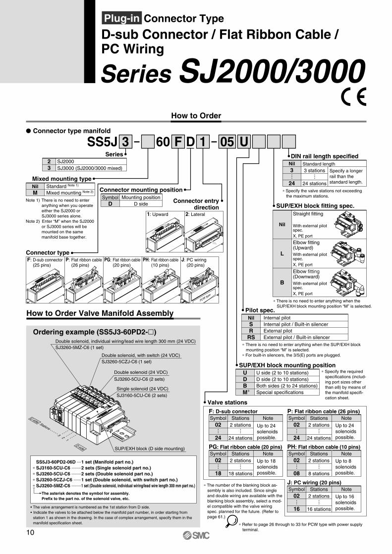
Symbol D
Mounting position D side
Connector mounting position
Connector entry direction
1: Upward 2: Lateral
60 DF 1 U
Series SJ2000/3000
SUP/EXH block fitting spec.
Nil
Straight fitting
L
Elbow fitting (Upward)
B
Elbow fitting (Downward)
Internal pilot Internal pilot / Built-in silencer External pilot External pilot / Built-in silencer
Pilot spec.Nil SR
RS
How to Order
SS5J 3P Connector type manifold
SeriesSJ2000SJ3000 (SJ2000/3000 mixed)
23
05
Mixed mounting typeNil M
Note 1) There is no need to enter anything when you operate either the SJ2000 or SJ3000 series alone.
Note 2) Enter “M” when the SJ2000 or SJ3000 series will be mounted on the same manifold base together.
Standard Note 1)
Mixed mounting Note 2)
With external pilot spec. X, PE port
With external pilot spec. X, PE port
With external pilot spec. X, PE port
F: D-sub connector
Valve stations
Note
Up to 24 solenoids possible.
2 stations
24 stations
Symbol Stations02
24
PG: Flat ribbon cable (20 pins)Note
Up to 18 solenoids possible.
2 stations
18 stations
Symbol Stations02
18
P: Flat ribbon cable (26 pins)Note
Up to 24 solenoids possible.
2 stations
24 stations
Symbol Stations02
24
PH: Flat ribbon cable (10 pins)Note
Up to 8 solenoids possible.
2 stations
8 stations
Symbol Stations02
08
∗ The number of the blanking block as-sembly is also included. Since single and double wiring are available with the blanking block assembly, select a mod-el compatible with the valve wiring spec. planned for the future. (Refer to page 61.)
∗ Specify the required specifications (includ-ing port sizes other than ø8) by means of the manifold specifi-cation sheet.
SUP/EXH block mounting positionUDBM∗
U side (2 to 10 stations) D side (2 to 10 stations) Both sides (2 to 24 stations) Special specifications
How to Order Valve Manifold Assembly
• The valve arrangement is numbered as the 1st station from D side.• Indicate the valves to be attached below the manifold part number, in order starting from
station 1 as shown in the drawing. In the case of complex arrangement, specify them in themanifold specification sheet.
The asterisk denotes the symbol for assembly. Prefix to the part no. of the solenoid valve, etc.
Ordering example (SS5J3-60PD2-l)
SS5J3-60PD2-06D 1 set (Manifold part no.) ∗ SJ3160-5CU-C6 2 sets (Single solenoid part no.) ∗ SJ3260-5CU-C6 2 sets (Double solenoid part no.) ∗ SJ3260-5CZJ-C6 1 set (Double solenoid, with switch part no.) ∗ SJ3260-5MZ-C6 1 set (Double solenoid, individual wiring/lead wire length 300 mm part no.)
D side
U side
13
2
Stations
SJ3260-5MZ-C6 (1 set)
SJ3260-5CZJ-C6 (1 set)Double solenoid, with switch (24 VDC)
Double solenoid, individual wiring/lead wire length 300 mm (24 VDC)
SJ3260-5CU-C6 (2 sets)
Double solenoid (24 VDC)
SJ3160-5CU-C6 (2 sets)Single solenoid (24 VDC)
SUP/EXH block (D side mounting)
D-sub Connector / Flat Ribbon Cable / PC Wiring
Plug-in Connector Type
F: D-sub connector (25 pins)
P: Flat ribbon cable (26 pins)
PG: Flat ribbon cable (20 pins)
PH: Flat ribbon cable (10 pins)
J: PC wiring (20 pins)
Connector type
PCW type
DIN rail length specified
Specify a longer rail than the standard length.
Standard length3 stations
24 stations
Nil3
24∗ Specify the valve stations not exceeding
the maximum stations.
∗ Refer to page 26 through to 33 for PCW type with power supply terminal.
∗ There is no need to enter anything when the SUP/EXH block mounting position “M” is selected.
∗ There is no need to enter anything when the SUP/EXH block mounting position “M” is selected.
∗ For built-in silencers, the 3/5(E) ports are plugged.
10

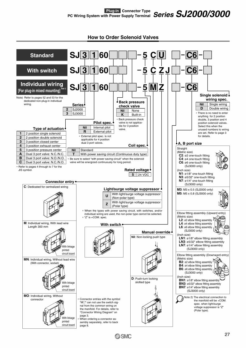
How to Order Solenoid Valves
SJ 3 1 U60 C6
SJ 3
Note) Refer to pages 52 and 53 for the dedicated non-plug-in individual wiring.
SJ 3 1 Z60 C6
1
5
5 M
5
C
C Z J60 C6
SeriesSJ2000 SJ3000
23
Internal pilot External pilot
Pilot spec.Nil R
∗ External pilot spec. is not applicable for 4 position dual 3 port valves.
None Built-in
Back pressure check valveNil K
∗ Back pressure check valve is not applica-ble for 3 position valve.
2 position single solenoid 2 position double solenoid 3 position closed center 3 position exhaust center 3 position pressure center Dual 3 port valve: N.C./N.C. Dual 3 port valve: N.O./N.O. Dual 3 port valve: N.C./N.O.
Type of actuation12345ABC
∗ Refer to pages 4 through to 7 for the JIS symbol.
Rated voltage24 VDC 12 VDC
56
Note 2) The electrical connection to the manifold will be +COM. spec. when light/surge voltage suppressor is “Z” (Polar type).
A, B port sizeStraight (Metric size) C2: ø2 one-touch fitting C4: ø4 one-touch fitting C6: ø6 one-touch fitting
(SJ3000 only) (Inch size) N1: ø1/8" one-touch fitting N3: ø5/32" one-touch fitting N7: ø1/4" one-touch fitting
(SJ3000 only)
M3: M3 x 0.5 (SJ2000 only) M5: M5 x 0.8 (SJ3000 only)
Elbow fitting assembly (Upward entry) (Metric size) L2: ø2 elbow fitting assembly L4: ø4 elbow fitting assembly
L6: ø6 elbow fitting assembly (SJ3000 only)
(Inch size) LN1: ø1/8" elbow fitting assembly LN3: ø5/32" elbow fitting assembly LN7: ø1/4" elbow fitting assembly
(SJ3000 only)
Elbow fitting assembly (Downward entry) (Metric size) B2: ø2 elbow fitting assembly B4: ø4 elbow fitting assembly B6: ø6 elbow fitting assembly
(SJ3000 only) (Inch size) BN1: ø1/8" elbow fitting assembly BN3: ø5/32" elbow fitting assembly BN7: ø1/4" elbow fitting assembly
(SJ3000 only)
Single wiring Double wiring
Single solenoid wiring spec.
Nil D
∗ There is no need to enter anything for 2 position double, 3 position and 4 position solenoid valves.Select this when the unused numbers to wiring are set. Refer to page 3 for details.
Manual overrideNil: Non-locking push type
D: Push-turn locking slotted type
With switch
∗ Connector entries with the symbol “Mm” can not use the switch sig-nal from the common wiring on the manifold. For details, refer to “Connector Wiring Diagram” on page 3.
∗ When ordering a connector as-sembly separately, refer to back page 8.
Connector entryC: Dedicated for centralized wiring
M: Individual wiring, With lead wire Length 300 mm
MN: Individual wiring, Without lead wire (With connector, socket)
MO: Individual wiring, Without connector
With linkage printed circuit board
With linkage printed circuit board
With linkage printed circuit board
Individual wiring [For plug-in mixed mounting]
Note 1)
With light/surge voltage suppressor (Non-polar type)
With light/surge voltage suppressor (Polar type)
Light/surge voltage suppressor
U
Z
∗ When the types with power saving circuit, with switches, and individual wiring are used, the non-polar type cannot be selected.
∗ “Z” is +COM. spec.
Standard With power saving circuit (Continuous duty type)
Coil spec.Nil T
∗ Be sure to select “with power saving circuit” when the solenoid valve will be energized continuously for long period.
With switch
Standard
11
Series SJ2000/3000D-sub Connector / Flat Ribbon Cable / PC WiringPlug-in Connector Type
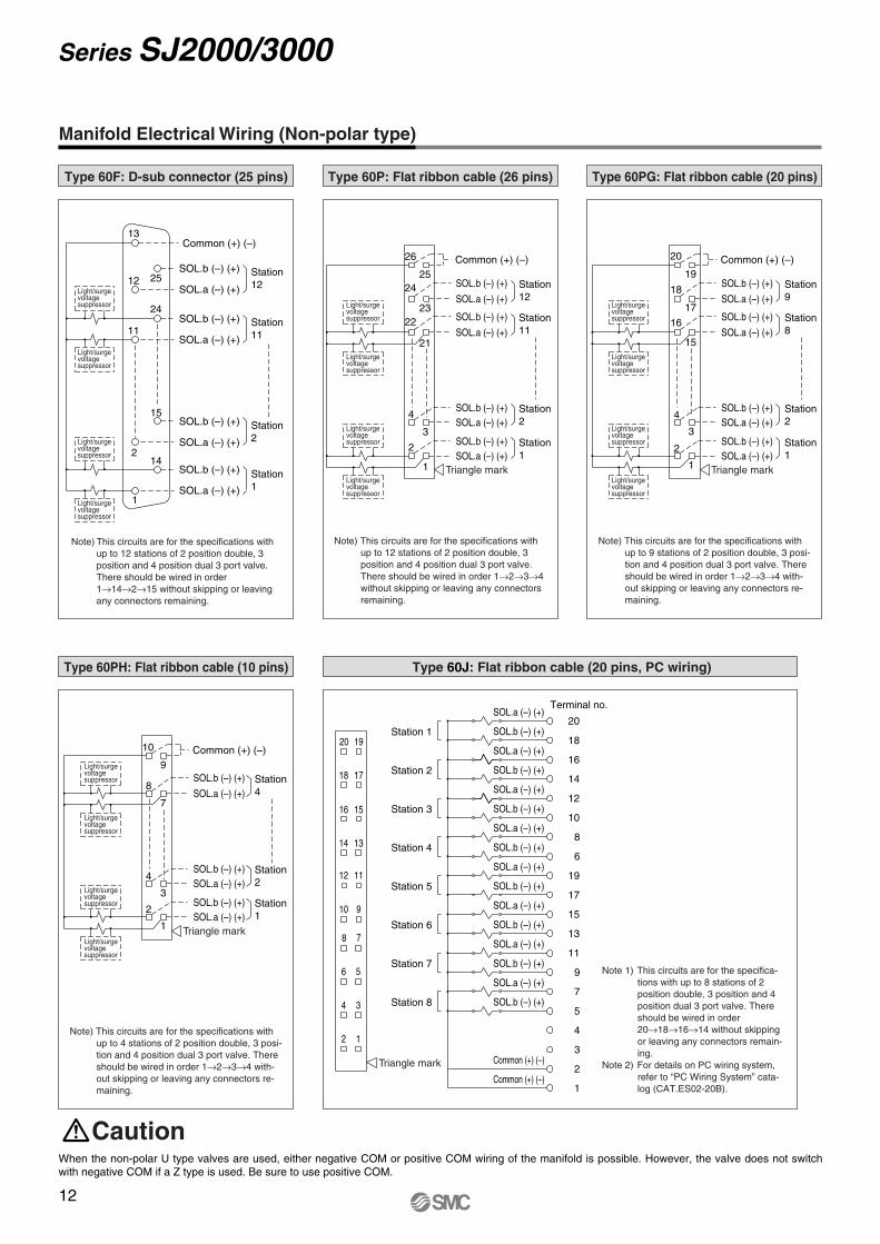
Manifold Electrical Wiring (Non-polar type)
Type 60F: D-sub connector (25 pins)
Note) This circuits are for the specifications with up to 12 stations of 2 position double, 3 position and 4 position dual 3 port valve. There should be wired in order 1→14→2→15 without skipping or leaving any connectors remaining.
Type 60P: Flat ribbon cable (26 pins)
Note) This circuits are for the specifications with up to 12 stations of 2 position double, 3 position and 4 position dual 3 port valve. There should be wired in order 1→2→3→4without skipping or leaving any connectors remaining.
Type 60PG: Flat ribbon cable (20 pins)
Note) This circuits are for the specifications with up to 9 stations of 2 position double, 3 posi-tion and 4 position dual 3 port valve. There should be wired in order 1→2→3→4 with-out skipping or leaving any connectors re-maining.
Type 60PH: Flat ribbon cable (10 pins)
Note) This circuits are for the specifications with up to 4 stations of 2 position double, 3 posi-tion and 4 position dual 3 port valve. There should be wired in order 1→2→3→4 with-out skipping or leaving any connectors re-maining.
Triangle mark
Triangle mark
Station 12
SOL.b (–) (+)
SOL.a (–) (+)
Station 11
SOL.b (–) (+)
SOL.a (–) (+)
Station 2
Station 1
15
2
SOL.b (–) (+)
SOL.a (–) (+)
Light/surge voltage suppressor
Light/surge voltage suppressor
Light/surge voltage suppressor
Light/surge voltage suppressor
Light/surge voltage suppressor
Light/surge voltage suppressor
Light/surge voltage suppressor
Light/surge voltage suppressor
Light/surge voltage suppressor
Light/surge voltage suppressor
Light/surge voltage suppressor
Light/surge voltage suppressor
Light/surge voltage suppressor
Light/surge voltage suppressor
Light/surge voltage suppressor
Light/surge voltage suppressor
SOL.b (–) (+)
11
12
13
25
24
SOL.a (–) (+)
Common (+) (–)
14
1
8
7
Station 4
3
Station 2
Station 1
SOL.b (–) (+)
SOL.a (–) (+)
SOL.b (–) (+)SOL.a (–) (+)
SOL.a (–) (+)SOL.b (–) (+)
Common (+) (–)10
9
4
2
1
Type 60J: Flat ribbon cable (20 pins, PC wiring)
Station 9
SOL.b (–) (+)
SOL.a (–) (+)
3
15
Station 8
Station 2
Station 1
SOL.b (–) (+)
SOL.a (–) (+)
SOL.b (–) (+)SOL.a (–) (+)
SOL.b (–) (+)SOL.a (–) (+)
Common (+) (–)20
19
18
17
16
4
2
1
Station 12
SOL.b (–) (+)
SOL.a (–) (+)
3
21
Station 11
Station 2
Station 1
SOL.b (–) (+)
SOL.a (–) (+)
SOL.b (–) (+)SOL.a (–) (+)
SOL.b (–) (+)SOL.a (–) (+)
Common (+) (–)26
2524
2322
4
2
1 Triangle mark
When the non-polar U type valves are used, either negative COM or positive COM wiring of the manifold is possible. However, the valve does not switch with negative COM if a Z type is used. Be sure to use positive COM.
Caution
Note 1) This circuits are for the specifica-tions with up to 8 stations of 2 position double, 3 position and 4 position dual 3 port valve. There should be wired in order 20→18→16→14 without skipping or leaving any connectors remain-ing.
Note 2) For details on PC wiring system, refer to “PC Wiring System” cata-log (CAT.ES02-20B).
SOL.b (–) (+)
SOL.a (–) (+)
SOL.b (–) (+)
SOL.a (–) (+)
SOL.b (–) (+)
SOL.a (–) (+)
SOL.b (–) (+)
SOL.a (–) (+)
SOL.b (–) (+)
SOL.a (–) (+)
SOL.b (–) (+)
SOL.a (–) (+)
SOL.b (–) (+)
SOL.a (–) (+)
Station 7
Station 6
Station 5
Station 4
Station 3
1112
910
78
1314
56
3
15
20 19
18 17
16
4
2 1
Triangle mark
Common (+) (–)
Common (+) (–)
SOL.b (–) (+)
SOL.a (–) (+)
Station 1
Station 2
Terminal no.
Station 8
1
2
3
4
5
7
9
11
13
15
17
19
6
8
10
12
14
16
18
20
12
Series SJ2000/3000
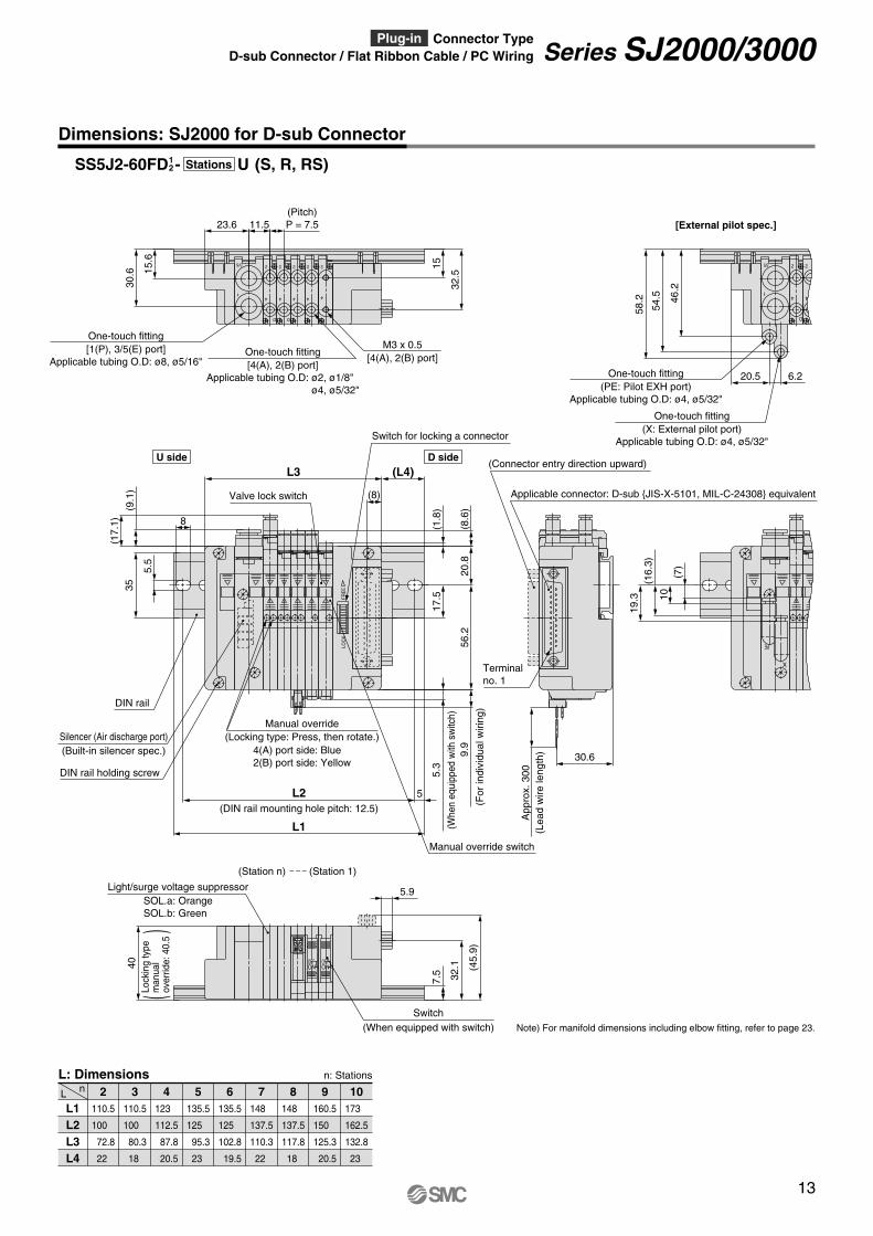
Dimensions: SJ2000 for D-sub Connector
L1 L2 L3 L4
2nL
L: Dimensions n: Stations
110.5
100
72.8
22
110.5
100
80.3
18
123
112.5
87.8
20.5
135.5
125
95.3
23
135.5
125
102.8
19.5
148
137.5
110.3
22
148
137.5
117.8
18
160.5
150
125.3
20.5
173
162.5
132.8
23
3 4 5 6 7 8 9 10
Note) For manifold dimensions including elbow fitting, refer to page 23.
5.5
DIN rail
3/5
1
PE
X
BA
D
2
4
FRE
ELO
CK
58.2
54.5 46
.2
19.3
(16.
3)
10(7
)
9.9
30.6
App
rox.
300
5.3
(17.
1)
(9.1
)
(8.6
)
(1.8
)
6.220.5
8
5
L1
L2
(L4)56
.2
17.5
20.8
35
L3
(8)
(For
indi
vidu
alw
iring
)(Connector entry direction upward)
(Whe
neq
uipp
edw
ithsw
itch)
2
4
One-touch fitting (PE: Pilot EXH port)
Applicable tubing O.D: ø4, ø5/32"
One-touch fitting (X: External pilot port)
Applicable tubing O.D: ø4, ø5/32"
[External pilot spec.]
(Built-in silencer spec.)Silencer (Air discharge port)
4(A) port side: Blue 2(B) port side: Yellow
Manual override (Locking type: Press, then rotate.)
Switch for locking a connector
Terminal no. 1
DIN rail holding screw
(DIN rail mounting hole pitch: 12.5)
2
4
D
2
4
D
2
4 4
22
4
3/5
1
(Pitch) P = 7.511.5
32.5
1515.6
23.6
30.6
One-touch fitting [4(A), 2(B) port]
Applicable tubing O.D: ø2, ø1/8" ø4, ø5/32"
M3 x 0.5 [4(A), 2(B) port]
One-touch fitting [1(P), 3/5(E) port]
Applicable tubing O.D: ø8, ø5/16"
OFFON
OFFON
5.9
40 (45.
9)
32.1
7.5
(When equipped with switch)Switch
SOL.a: Orange SOL.b: Green
Light/surge voltage suppressor
Applicable connector: D-sub JIS-X-5101, MIL-C-24308 equivalent
(Lea
dw
irele
ngth
)
U side D side
(Station n) (Station 1)
Valve lock switch
Manual override switch
SS5J2-60FD - U (S, R, RS)12 Stations
()
Lock
ing
type
man
ual
over
ride:
40.5
13
Series SJ2000/3000D-sub Connector / Flat Ribbon Cable / PC Wiring Plug-in Connector Type
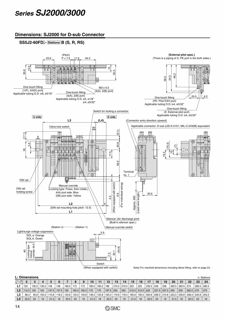
Dimensions: SJ2000 for D-sub Connector
L1 L2 L3 L4
2nL
L: Dimensions n: Stations
123
112.5
88.3
20.5
135.5
125
95.8
23
135.5
125
103.3
19
148
137.5
110.8
21.5
148
137.5
118.3
18
160.5
150
125.8
20.5
173
162.5
133.3
23
173
162.5
140.8
19
185.5
175
148.3
21.5
185.5
175
155.8
18
198
187.5
163.3
20.5
210.5
200
170.8
23
210.5
200
178.3
19
223
212.5
185.8
21.5
223
212.5
193.3
18
235.5
225
200.8
20.5
248
237.5
208.3
23
248
237.5
215.8
19
260.5
250
223.3
21.5
260.5
250
230.8
18
273
262.5
238.3
20.5
285.5
275
245.8
23
285.5
275
253.3
19
3 4 5 6 7 8 9 10 11 12 13 14 15 16 17 18 19 20 21 22 23 24
Note) For manifold dimensions including elbow fitting, refer to page 23.
2
4
D
2
4
D
2
4 4
22
4
3/5
1
3/5
1
11.5
32.5
1515.6
34.323.6
30.6
(Pitch) P = 7.5
One-touch fitting [4(A), 2(B) port]
Applicable tubing O.D: ø2, ø1/8" ø4, ø5/32"
M3 x 0.5 [4(A), 2(B) port]
One-touch fitting [1(P), 3/5(E) port]
Applicable tubing O.D: ø8, ø5/16"
[External pilot spec.] (There is a piping of X, PE port in the both sides.)
(Whe
neq
uipp
edw
ithsw
itch)
(For
indi
vidu
alw
iring
)
PE
X
3/5
1
BA
OFFON
OFFON
D
2
4
FRE
ELO
CK
54.5 46
.2
58.2
19.3
(16.
3)10
(7)
30.6
App
rox.
300
5.3
(17.
1) (9.1
)
6.220.5
5
L1
L2
(L4)
8
35
5.5
L3
(8)
5.9
40 (45.
9)
32.1
7.5
20.8
56.2
17.5
One-touch fitting (PE: Pilot EXH port)
Applicable tubing O.D: ø4, ø5/32"
One-touch fitting (X: External pilot port)
Applicable tubing O.D: ø4, ø5/32"
(Connector entry direction upward)
Applicable connector: D-sub JIS-X-5101, MIL-C-24308 equivalent
(When equipped with switch)Switch
2
4
Terminal no. 1
(Built-in silencer spec.)Silencer (Air discharge port)
DIN rail holding screw
DIN rail
SOL.a: Orange SOL.b: Green
Light/surge voltage suppressor
(DIN rail mounting hole pitch: 12.5)
(Lea
dw
irele
ngth
)
9.9
(Station n) (Station 1)
Switch for locking a connector
Valve lock switch
Manual override switch
U side D side
SS5J2-60FD - B (S, R, RS)12 Stations
4(A) port side: Blue 2(B) port side: Yellow
Manual override (Locking type: Press, then rotate.)
()
Lock
ing
type
man
ual
over
ride:
40.5
14
Series SJ2000/3000
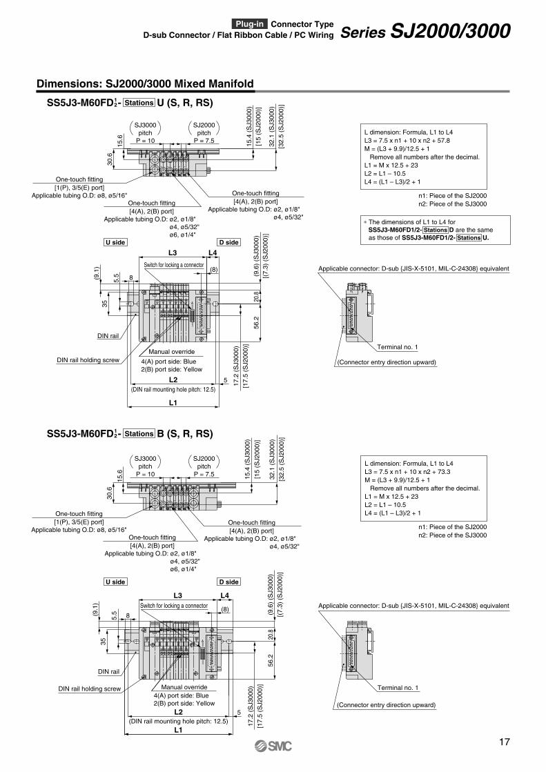
Dimensions: SJ2000/3000 Mixed Manifold
n1: Piece of the SJ2000 n2: Piece of the SJ3000
L dimension: Formula, L1 to L4 L3 = 7.5 x n1 + 10 x n2 + 57.8 M = (L3 + 9.9)/12.5 + 1 Remove all numbers after the decimal. L1 = M x 12.5 + 23 L2 = L1 – 10.5 L4 = (L1 – L3)/2 + 1
n1: Piece of the SJ2000 n2: Piece of the SJ3000
L dimension: Formula, L1 to L4 L3 = 7.5 x n1 + 10 x n2 + 73.3 M = (L3 + 9.9)/12.5 + 1 Remove all numbers after the decimal. L1 = M x 12.5 + 23 L2 = L1 – 10.5 L4 = (L1 – L3)/2 + 1
[32.
5(S
J200
0)]
One-touch fitting [4(A), 2(B) port]
Applicable tubing O.D: ø2, ø1/8" ø4, ø5/32"
4(A) port side: Blue 2(B) port side: Yellow
Manual override
5.5
3/5
1
2
4
D
2
4
D D
2
4
D
2
4
D
2
4
3/5
1
FRE
ELO
CK
2
4
D
2
4
D D
2
4
D
2
4
D
2
4
3/5
1
FRE
ELO
CK
8(9.1
)35
(9.6
)(S
J300
0)
17.2
(SJ3
000)
56.2
20.8
32.1
(SJ3
000)
15.4
(SJ3
000)
(9.1
)
(9.6
)(S
J300
0)
17.2
(SJ3
000)
8
56.2
20.8
35
32.1
(SJ3
000)
15.4
(SJ3
000)
(8)
5L2
L1
L4L3
5L2
L1
L4L3
15.6
30.6
(8)
15.6
30.6
[17.
5(S
J200
0)]
[(7.
3)(S
J200
0)]
[32.
5(S
J200
0)]
[15
(SJ2
000)
]
[17.
5(S
J200
0)]
[(7.
3)(S
J200
0)]
[15
(SJ2
000)
]
One-touch fitting [4(A), 2(B) port]
Applicable tubing O.D: ø2, ø1/8" ø4, ø5/32"
One-touch fitting [4(A), 2(B) port]
Applicable tubing O.D: ø2, ø1/8" ø4, ø5/32" ø6, ø1/4"
(Connector entry direction upward)
Terminal no. 1
One-touch fitting [1(P), 3/5(E) port]
Applicable tubing O.D: ø8, ø5/16"
DIN rail holding screw
DIN rail
(DIN rail mounting hole pitch: 12.5)
Switch for locking a connector
One-touch fitting [1(P), 3/5(E) port]
Applicable tubing O.D: ø8, ø5/16"
DIN rail holding screw
DIN rail
(DIN rail mounting hole pitch: 12.5)
One-touch fitting [4(A), 2(B) port]
Applicable tubing O.D: ø2, ø1/8" ø4, ø5/32" ø6, ø1/4"
SJ3000 pitch
P = 10
SJ2000 pitch
P = 7.5
SJ3000 pitch
P = 10
SJ2000 pitch
P = 7.5
4(A) port side: Blue 2(B) port side: Yellow
Manual override
(Connector entry direction upward)
Terminal no. 1
Applicable connector: D-sub JIS-X-5101, MIL-C-24308 equivalent
Applicable connector: D-sub JIS-X-5101, MIL-C-24308 equivalent
5.5
Switch for locking a connector
SS5J3-M60FD - U (S, R, RS)12 Stations
SS5J3-M60FD - B (S, R, RS)12 Stations
U side D side
U side D side
∗ The dimensions of L1 to L4 for SS5J3-M60FD1/2- Stations D are the same as those of SS5J3-M60FD1/2- Stations U.
17
Series SJ2000/3000D-sub Connector / Flat Ribbon Cable / PC Wiring Plug-in Connector Type
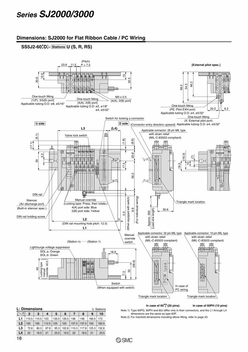
Dimensions: SJ2000 for Flat Ribbon Cable / PC Wiring
L1 L2 L3 L4
2nL
L: Dimensions n: Stations
110.5
100
72.8
22
110.5
100
80.3
18.5
123
112.5
87.8
21
135.5
125
95.3
23.5
135.5
125
102.8
19.5
148
137.5
110.3
22
148
137.5
117.8
18.5
160.5
150
125.3
21
173
162.5
132.8
23.5
3 4 5 6 7 8 9 10
2
4
D
2
4
D
2
4 4
22
4
3/5
1
(Pitch) P = 7.511.5
32.5
1515.6
23.6
30.6
One-touch fitting [4(A), 2(B) port]
Applicable tubing O.D: ø2, ø1/8" ø4, ø5/32"
M3 x 0.5 [4(A), 2(B) port]
One-touch fitting [1(P), 3/5(E) port]
Applicable tubing O.D: ø8, ø5/16"
Triangle mark location Triangle mark location
In case of 60PH (10 pins)In case of 60 (20 pins)
Applicable connector: 20 pin MIL type with strain relief (MIL-C-83503 compliant)
Applicable connector: 10 pin MIL type with strain relief (MIL-C-83503 compliant)
PE
X
3/5
1
BA
OFFON
OFFON
D
2
4
LOC
K
54.5
58.2 46
.2
19.3
(16.
3)
10
(7)
30.6
App
rox.
3009.
9
5.3
(17.
1)
(9.1
)
(8.6
)
(1.8
)
32
(8)
6.220.5
8
35
5.5
56.2
5
L1
L2
(L4)17
.5
18.9
(58.
9)20
.8L3
40
7.5
One-touch fitting (PE: Pilot EXH port)
Applicable tubing O.D: ø4, ø5/32"One-touch fitting
(X: External pilot port) Applicable tubing O.D: ø4, ø5/32"(Connector entry direction upward)
(Whe
neq
uipp
edw
ithsw
itch)
(When equipped with switch)Switch
(For
indi
vidu
alw
iring
)
2
4
[External pilot spec.]
(Built-in silencer spec.)
Silencer (Air discharge port)
Triangle mark location
DIN rail holding screw
DIN rail
SOL.a: Orange SOL.b: Green
Light/surge voltage suppressor
(DIN rail mounting hole pitch: 12.5)
Applicable connector: 26 pin MIL type with strain relief (MIL-C-83503 compliant)
(Lea
dw
irele
ngth
)
FRE
E
Switch for locking a connector
Valve lock switch
Manual override switch
PG J
Note 1) Type 60PG, 60PH and 60J differ only in their connectors, and the L1 through L4 dimensions are the same as type 60P.
Note 2) For manifold dimensions including elbow fitting, refer to page 23.
In case of PC wiring
(Station n) (Station 1)
U side D side
SS5J2-60 D - U (S, R, RS)12
PJ Stations
4(A) port side: Blue 2(B) port side: Yellow
Manual override (Locking type: Press, then rotate.)
()
Lock
ing
type
man
ual
over
ride:
40.5
18
Series SJ2000/3000
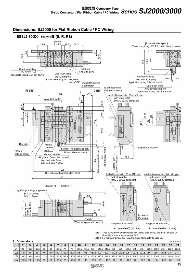
Dimensions: SJ2000 for Flat Ribbon Cable / PC Wiring
L1 L2 L3 L4
2nL
L: Dimensions n: Stations
123
112.5
88.3
20.5
135.5
125
95.8
23
135.5
125
103.3
19.5
148
137.5
110.8
22
148
137.5
118.3
18
160.5
150
125.8
20.5
173
162.5
133.3
23
173
162.5
140.8
19.5
185.5
175
148.3
22
185.5
175
155.8
18
198
187.5
163.3
20.5
210.5
200
170.8
23
210.5
200
178.3
19.5
223
212.5
185.8
22
223
212.5
193.3
18
235.5
225
200.8
20.5
248
237.5
208.3
23
248
237.5
215.8
19.5
260.5
250
223.3
22
260.5
250
230.8
18
273
262.5
238.3
20.5
285.5
275
245.8
23
285.5
275
253.3
19.5
3 4 5 6 7 8 9 10 11 12 13 14 15 16 17 18 19 20 21 22 23 24
Applicable connector: 20 pin MIL type with strain relief (MIL-C-83503 compliant)
Applicable connector: 10 pin MIL type with strain relief (MIL-C-83503 compliant)
Triangle mark locationTriangle mark location
2
4
D
2
4
D
2
4 4
22
4
3/5
1
3/5
1
(Pitch) P = 7.5 11.5
32.5
1515.6
34.323.6
30.6
One-touch fitting [4(A), 2(B) port]
Applicable tubing O.D: ø2, ø1/8" ø4, ø5/32"
M3 x 0.5 [4(A), 2(B) port]
One-touch fitting [1(P), 3/5(E) port]
Applicable tubing O.D: ø8, ø5/16"
PE
X
3/5
1
BA
OFFON
OFFON
D
2
4
FRE
ELO
CK
58.2 46
.2
54.5
19.3
(16.
3)10
(7)
30.6
App
rox.
3009.
9
5.3
(9.1
)
(17.
1)
32(8)
6.220.5
5
8
L1
L2
(L4)L3
35
5.5
(18.9)
(58.
9)
40
7.5
20.8
56.2
17.5
One-touch fitting (PE: Pilot EXH port)
Applicable tubing O.D: ø4, ø5/32"
One-touch fitting (X: External pilot port)
Applicable tubing O.D: ø4, ø5/32"
(Lea
dw
irele
ngth
)
(Connector entry direction upward)
(For
indi
vidu
alw
iring
)
(When equipped with switch)Switch
2
4
[External pilot spec.] (There is a piping of X, PE port in the both sides.)
Triangle mark location
DIN rail holding screw
DIN rail
SOL.a: Orange SOL.b: Green
Light/surge voltage suppressor
(DIN rail mounting hole pitch: 12.5)
(Built-in silencer spec.)
Silencer (Air discharge port)
Applicable connector: 26 pin MIL type with strain relief (MIL-C-83503 compliant)
(Whe
neq
uipp
edw
ithsw
itch)
Switch for locking a connector
Valve lock switch
Manual override switch
Note 1) Type 60PG, 60PH and 60J differ only in their connectors, and the L1 through L4 dimensions are the same as type 60P.
Note 2) For manifold dimensions including elbow fitting, refer to page 23.
SS5J2-60 D - B (S, R, RS)12
PJ Stations
(Station n) (Station 1)
U side D side
4(A) port side: Blue 2(B) port side: Yellow
Manual override (Locking type: Press, then rotate.)
In case of 60PH (10 pins)In case of 60 (20 pins)PG J
()
Lock
ing
type
man
ual
over
ride:
40.5
In case of PC wiring
19
Series SJ2000/3000D-sub Connector / Flat Ribbon Cable / PC Wiring Plug-in Connector Type
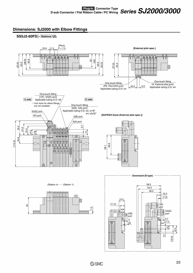
Dimensions: SJ2000 with Elbow Fittings
22 2223/5
(53.
5)
50.5(3
6)33
50.9 35
.9
(53.
9) (38.
9)
P = 7.511.523.6(Pitch)
FRE
ELO
CK
14
5.7
22.5
14.2
(112
.2) 20
.835
.2
27.6
11.6
2(B) port
4(A) port
One-touch fitting [1(P), 3/5(E) port]
Applicable tubing O.D: ø8
One-touch fitting [2(B), 4(A) port]
Applicable tubing O.D: ø2, ø1/8" ø4, ø5/32"
∗ Inch sizes for elbow fittings are not available.
3/5(E) port
1(P) port
40
7.5
58.1 48
.8
[SUP/EXH block (External pilot spec.)]
22 2223/5
55.3
(57.
6)
6.220.5One-touch fitting
(PE: Pilot EXH port) Applicable tubing O.D: ø4
One-touch fitting (X: External pilot port)
Applicable tubing O.D: ø4
[External pilot spec.]
(16.
3)
19.3
(7)
10
58.2
54.546.2
14.5
(11.5)
(6)
3 4.7
10.3
(7.3)
(7.7)
1(P) 1(P)portport
4(A) 4(A)portport
1(P) port
3/5(E) port
4(A) port
2(B) port
[Valve] [SUP/EXH block (External pilot spec.)]
Downward (B type)
(Station n) (Station 1)
U side D side
SS5J2-60FD - U12
LBStations
23
Series SJ2000/3000D-sub Connector / Flat Ribbon Cable / PC Wiring Plug-in Connector Type
• The valve arrangement is numbered as the 1st station from D side.• Indicate the valves to be attached below the manifold part number, in order starting from
station 1 as shown in the drawing. In the case of complex arrangement, specify them in themanifold specification sheet.
The asterisk denotes the symbol for assembly. Prefix to the part no. of the solenoid valve, etc.
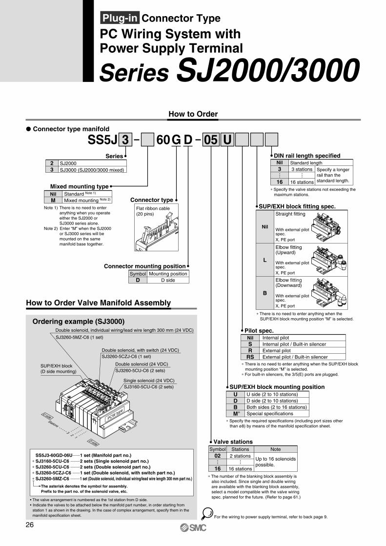
SS5J3-60GD-06U 1 set (Manifold part no.) ∗ SJ3160-5CU-C6 2 sets (Single solenoid part no.) ∗ SJ3260-5CU-C6 2 sets (Double solenoid part no.) ∗ SJ3260-5CZJ-C6 1 set (Double solenoid, with switch part no.) ∗ SJ3260-5MZ-C6 1 set (Double solenoid, individual wiring/lead wire length 300 mm part no.)
Symbol D
Mounting position D side
Connector mounting position
60 DG U
How to Order
SS5J 3P Connector type manifold
SeriesSJ2000SJ3000 (SJ2000/3000 mixed)
23
05
Mixed mounting typeNil M
Note 1) There is no need to enter anything when you operate either the SJ2000 or SJ3000 series alone.
Note 2) Enter “M” when the SJ2000 or SJ3000 series will be mounted on the same manifold base together.
Standard Note 1)
Mixed mounting Note 2)
Valve stations
∗ The number of the blanking block assembly is also included. Since single and double wiring are available with the blanking block assembly, select a model compatible with the valve wiring spec. planned for the future. (Refer to page 61.)
∗ Specify the required specifications (including port sizes other than ø8) by means of the manifold specification sheet.
SUP/EXH block mounting positionUDBM∗
U side (2 to 10 stations) D side (2 to 10 stations) Both sides (2 to 16 stations) Special specifications
How to Order Valve Manifold Assembly
Ordering example (SJ3000)
13
2
For the wiring to power supply terminal, refer to back page 9.
Flat ribbon cable (20 pins)
Connector type
Note
Up to 16 solenoids possible.
2 stations
16 stations
Symbol Stations02
16
PCWtype
SJ3260-5MZ-C6 (1 set)
Double solenoid, individual wiring/lead wire length 300 mm (24 VDC)
SJ3260-5CZJ-C6 (1 set)Double solenoid, with switch (24 VDC)
SJ3260-5CU-C6 (2 sets)Double solenoid (24 VDC)
SJ3160-5CU-C6 (2 sets)Single solenoid (24 VDC)
SUP/EXH block (D side mounting)
DIN rail length specified
∗ Specify the valve stations not exceeding the maximum stations.
SUP/EXH block fitting spec.
Nil
Straight fitting
L
Elbow fitting (Upward)
B
Elbow fitting (Downward)
With external pilot spec. X, PE port
With external pilot spec. X, PE port
With external pilot spec. X, PE port
PCWtype
PCWtype
PCWtype
Internal pilot Internal pilot / Built-in silencer External pilot External pilot / Built-in silencer
Pilot spec.Nil SR
RS
Stations
D side
U side
Specify a longer rail than the standard length.
Standard length3 stations
16 stations
Nil3
16
∗ There is no need to enter anything when the SUP/EXH block mounting position “M” is selected.
∗ There is no need to enter anything when the SUP/EXH block mounting position “M” is selected.
∗ For built-in silencers, the 3/5(E) ports are plugged.
Series SJ2000/3000
26
PC Wiring System with Power Supply Terminal
Plug-in Connector Type
How to Order Solenoid Valves
SJ 3 1 U60 C6
SJ 3
Note) Refer to pages 52 and 53 for the dedicated non-plug-in individual wiring.
SJ 3 1 Z60 C6
1
5
5 M
5
C
C Z J60 C6
SeriesSJ2000 SJ3000
23
Internal pilot External pilot
Pilot spec.Nil R
∗ External pilot spec. is not applicable for 4 position dual 3 port valves.
None Built-in
Back pressure check valveNil K
∗ Back pressure check valve is not applica-ble for 3 position valve.
2 position single solenoid 2 position double solenoid 3 position closed center 3 position exhaust center 3 position pressure center Dual 3 port valve: N.C./N.C. Dual 3 port valve: N.O./N.O. Dual 3 port valve: N.C./N.O.
Type of actuation12345ABC
∗ Refer to pages 4 through to 7 for the JIS symbol. Rated voltage
24 VDC5
Note 2) The electrical connection to the manifold will be +COM. spec. when light/surge voltage suppressor is “Z” (Polar type).
A, B port sizeStraight (Metric size) C2: ø2 one-touch fitting C4: ø4 one-touch fitting C6: ø6 one-touch fitting
(SJ3000 only) (Inch size) N1: ø1/8" one-touch fitting N3: ø5/32" one-touch fitting N7: ø1/4" one-touch fitting
(SJ3000 only)
M3: M3 x 0.5 (SJ2000 only) M5: M5 x 0.8 (SJ3000 only)
Elbow fitting assembly (Upward entry) (Metric size) L2: ø2 elbow fitting assembly L4: ø4 elbow fitting assembly
L6: ø6 elbow fitting assembly (SJ3000 only)
(Inch size) LN1: ø1/8" elbow fitting assembly LN3: ø5/32" elbow fitting assembly LN7: ø1/4" elbow fitting assembly
(SJ3000 only)
Elbow fitting assembly (Downward entry) (Metric size) B2: ø2 elbow fitting assembly B4: ø4 elbow fitting assembly B6: ø6 elbow fitting assembly
(SJ3000 only) (Inch size) BN1: ø1/8" elbow fitting assembly BN3: ø5/32" elbow fitting assembly BN7: ø1/4" elbow fitting assembly
(SJ3000 only)
Single wiring Double wiring
Single solenoid wiring spec.
Nil D
∗ There is no need to enter anything for 2 position double, 3 position and 4 position solenoid valves.Select this when the unused numbers to wiring are set. Refer to page 3 for details.
Manual overrideNil: Non-locking push type
D: Push-turn locking slotted type
With switch
Connector entryC: Dedicated for centralized wiring
M: Individual wiring, With lead wire Length 300 mm
MN: Individual wiring, Without lead wire (With connector, socket)
MO: Individual wiring, Without connector
With linkage printed circuit board
With linkage printed circuit board
With linkage printed circuit board
Light/surge voltage suppressor
Coil spec.
Individual wiring [For plug-in mixed mounting]
Note 1)
With light/surge voltage suppressor (Non-polar type)
With light/surge voltage suppressor (Polar type)
U
Z
∗ When the types with power saving circuit, with switches, and/or individual wiring are used, the non-polar type cannot be selected.
∗ “Z” is +COM. spec.
With switch
Standard
Standard With power saving circuit (Continuous duty type)
Nil T
∗ Be sure to select “with power saving circuit” when the solenoid valve will be energized continuously for long period.
∗ Connector entries with the symbol “Mm” can not use the switch sig-nal from the common wiring on the manifold. For details, refer to “Connector Wiring Diagram” on page 3.
∗ When ordering a connector as-sembly separately, refer to back page 8.
27
Series SJ2000/3000PC Wiring System with Power Supply TerminalPlug-in Connector Type
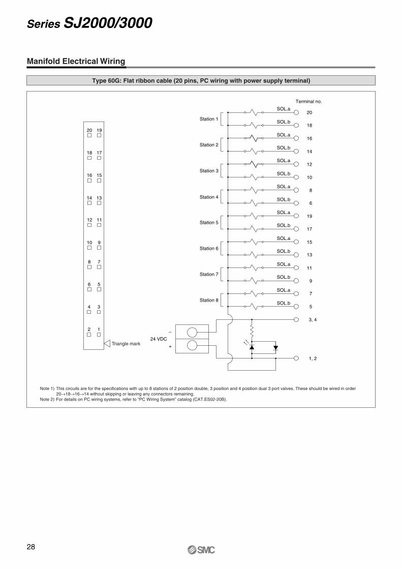
Manifold Electrical Wiring
Type 60G: Flat ribbon cable (20 pins, PC wiring with power supply terminal)
Triangle mark
20 19
18 17
16 15
14 13
12 11
10 9
8 7
6 5
4 3
2 1
24 VDC
+
–
Station 1
Station 2
Station 3
Station 4
Station 5
Station 6
Station 7
Station 8
Terminal no.
20
18
16
14
12
10
8
6
19
17
15
13
11
9
7
5
3, 4
1, 2
SOL.a
SOL.b
SOL.a
SOL.b
SOL.a
SOL.b
SOL.a
SOL.b
SOL.a
SOL.b
SOL.a
SOL.b
SOL.a
SOL.b
SOL.a
SOL.b
Note 1) This circuits are for the specifications with up to 8 stations of 2 position double, 3 position and 4 position dual 3 port valves. These should be wired in order 20→18→16→14 without skipping or leaving any connectors remaining.
Note 2) For details on PC wiring systems, refer to “PC Wiring System” catalog (CAT.ES02-20B).
28
Series SJ2000/3000
1
3/5
4
2 2
44
2
D
4
2
D
4
2
One-touch fitting [1(P), 3/5(E) port]
Applicable tubing O.D: ø8, ø5/16"
M3 x 0.5 [4(A), 2(B) port]
One-touch fitting [4(A), 2(B) port]
Applicable tubing O.D: ø2, ø1/8" ø4, ø5/32"
(Pitch) P = 7.5
30.6
23.6
15.6 15
32.5
11.5
X
PE
(7)
10
(16.
3)
19.3
4
2
D
1
3/5
One-touch fitting (X: External pilot port)
Applicable tubing O.D: ø4, ø5/32"
One-touch fitting (PE: Pilot EXH port)
Applicable tubing O.D: ø4, ø5/32"
4
2
20.5 6.2
46.2
54.5
58.2
Triangle mark location
PC
Wty
pe
(Lea
dw
irele
ngth
)A
ppro
x.30
0 30.6
+ -
24VDC+COM
A B
DIN rail
DIN rail holding screw
Silencer (Air discharge port)
(Built-in silencer spec.)
(Whe
neq
uipp
edw
ithsw
itch)
(For
indi
vidu
alw
iring
)
Valve lock switch
Manual override switch
Applicable connector: 20 pin MIL type with strain relief (MIL-C-83503 compliant)
35
20.8
17.5
56.2
(1.8
)
(8.6
)(9.1
)
(17.
1)
L3
23.6
30.3
(L4)
8
5.5
L2 (DIN rail mounting hole pitch: 12.5)
L1
5
5.3
9.9
Power supply terminal
(Station n) (Station 1)
ONOFF
ONOFF
Switch(When equipped with switch)
7.540
59.7
Light/surge voltage suppressor
U side D side
SOL.a: Orange SOL.b: Green
4(A) port side: Blue 2(B) port side: Yellow
Manual override (Locking type: Press, then rotate.)
()
Lock
ing
type
man
ual
over
ride:
40.5
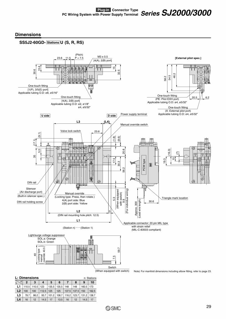
Dimensions
L1 L2 L3 L4
2nL
L: Dimensions n: Stations
110.5
100
78.7
16
110.5
100
86.2
12
123
112.5
93.7
14.5
135.5
125
101.2
17
135.5
125
108.7
13.5
148
137.5
116.2
16
148
137.5
123.7
12
160.5
150
131.2
14.5
173
162.5
138.7
17
3 4 5 6 7 8 9 10
SS5J2-60GD- U (S, R, RS)Stations
[External pilot spec.]
Note) For manifold dimensions including elbow fitting, refer to page 23.
29
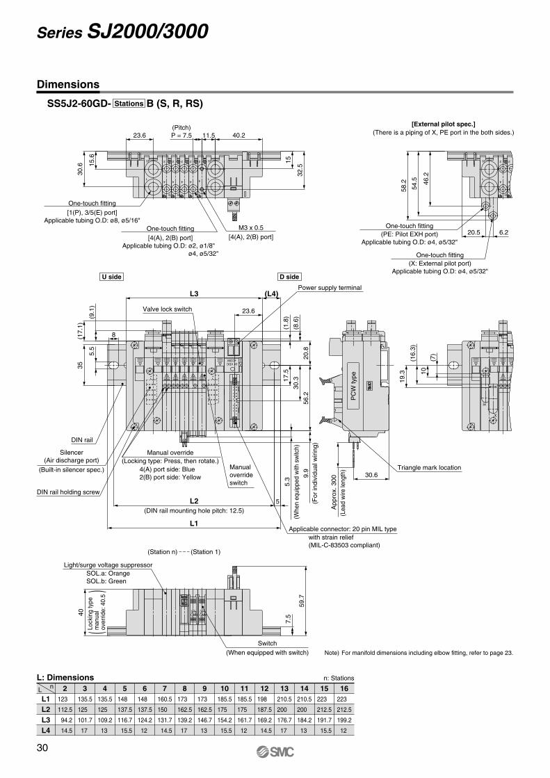
Series SJ2000/3000PC Wiring System with Power Supply Terminal Plug-in Connector Type
ONOFF
ONOFF
Light/surge voltage suppressor
Switch (When equipped with switch)
7.540
59.7
1
3/5
4
2 2
44
2
D
4
2
D
4
2
1
3/5
One-touch fitting [1(P), 3/5(E) port]
Applicable tubing O.D: ø8, ø5/16"M3 x 0.5
[4(A), 2(B) port]One-touch fitting [4(A), 2(B) port]
Applicable tubing O.D: ø2, ø1/8" ø4, ø5/32"
(Pitch) P = 7.5
30.6
23.6
15.6
15
32.5
40.211.5
A B
+ -
24VDC+COM
DIN rail
DIN rail holding screw
Silencer (Air discharge port)
(Built-in silencer spec.)
(Whe
neq
uipp
edw
ithsw
itch)
(For
indi
vidu
alw
iring
)Valve lock switch
Manual override switch
Applicable connector: 20 pin MIL type with strain relief (MIL-C-83503 compliant)
35
20.8
17.5
56.2
(1.8
)
(8.6
)(9.1
)
(17.
1)
L3
23.6
30.3
Power supply terminal
5.5
5.3 9.
9
(L4)
L2 (DIN rail mounting hole pitch: 12.5)
L1
5
8
4
2
D
1
3/5
One-touch fitting (X: External pilot port)
Applicable tubing O.D: ø4, ø5/32"
One-touch fitting (PE: Pilot EXH port)
Applicable tubing O.D: ø4, ø5/32"
4
2
20.5 6.2
46.2
54.5
58.2
X
PE
(7)
10
(16.
3)
19.3
PC
Wty
pe
(Lea
dw
irele
ngth
) Triangle mark location
App
rox.
300 30.6
U side D side
(Station n) (Station 1)
SOL.a: Orange SOL.b: Green
4(A) port side: Blue 2(B) port side: Yellow
Manual override (Locking type: Press, then rotate.)
()
Lock
ing
type
man
ual
over
ride:
40.5
Dimensions
L1 L2 L3 L4
2nL
L: Dimensions n: Stations
123
112.5
94.2
14.5
135.5
125
101.7
17
135.5
125
109.2
13
148
137.5
116.7
15.5
148
137.5
124.2
12
160.5
150
131.7
14.5
173
162.5
139.2
17
173
162.5
146.7
13
185.5
175
154.2
15.5
185.5
175
161.7
12
198
187.5
169.2
14.5
210.5
200
176.7
17
210.5
200
184.2
13
223
212.5
191.7
15.5
223
212.5
199.2
12
3 4 5 6 7 8 9 10 11 12 13 14 15 16
SS5J2-60GD- B (S, R, RS)Stations
[External pilot spec.] (There is a piping of X, PE port in the both sides.)
Note) For manifold dimensions including elbow fitting, refer to page 23.
30
Series SJ2000/3000
• The valve arrangement is numbered as the 1st station from D side.• Indicate the valves to be attached below the manifold part number, in order starting from
station 1 as shown in the drawing. In the case of complex arrangement, specify them in themanifold specification sheet.
The asterisk denotes the symbol for assembly. Prefix to the part no. of the solenoid valve, etc.
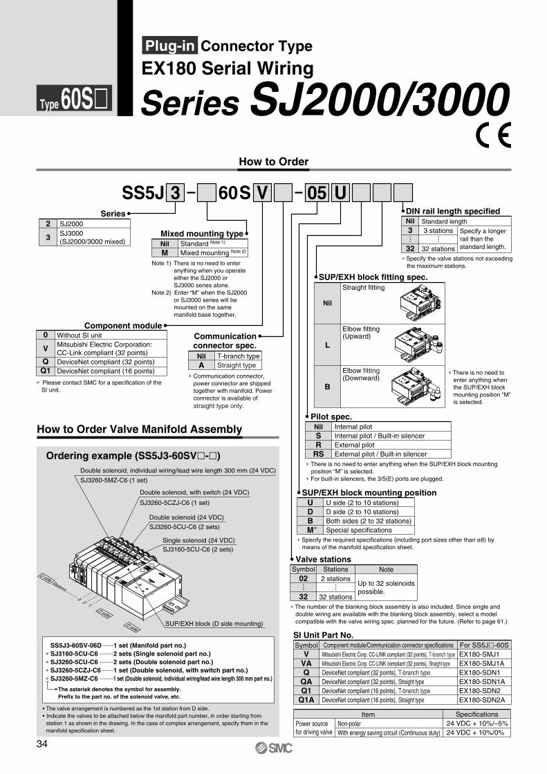
SS5J3-60SV-06D 1 set (Manifold part no.) ∗ SJ3160-5CU-C6 2 sets (Single solenoid part no.) ∗ SJ3260-5CU-C6 2 sets (Double solenoid part no.) ∗ SJ3260-5CZJ-C6 1 set (Double solenoid, with switch part no.) ∗ SJ3260-5MZ-C6 1 set (Double solenoid, individual wiring/lead wire length 300 mm part no.)
How to Order Valve Manifold Assembly
Ordering example (SS5J3-60SVl-l)
D side
V U
Communication connector spec.
Nil A
T-branch type Straight type
∗ Specify the required specifications (including port sizes other than ø8) by means of the manifold specification sheet.
SUP/EXH block mounting positionUDBM∗
U side (2 to 10 stations) D side (2 to 10 stations) Both sides (2 to 32 stations) Special specifications
SS5J 60S3Series
SJ2000SJ3000 (SJ2000/3000 mixed)
2
3
Component module
Mixed mounting typeNil M
Note 1) There is no need to enter anything when you operate either the SJ2000 or SJ3000 series alone.
Note 2) Enter “M” when the SJ2000 or SJ3000 series will be mounted on the same manifold base together.
Standard Note 1)
Mixed mounting Note 2)
Type 60Sl
∗ Communication connector, power connector are shipped together with manifold. Power connector is available of straight type only.
SI Unit Part No.Symbol
VVA Q
QA Q1
Q1A
For SS5Jl-60SEX180-SMJ1 EX180-SMJ1A EX180-SDN1 EX180-SDN1A EX180-SDN2 EX180-SDN2A
Component module/Communication connector specificationsMitsubishi Electric Corp. CC-LINK compliant (32 points), T-branch typeMitsubishi Electric Corp. CC-LINK compliant (32 points), Straight type DeviceNet compliant (32 points), T-branch type DeviceNet compliant (32 points), Straight typeDeviceNet compliant (16 points), T-branch type DeviceNet compliant (16 points), Straight type
∗ The number of the blanking block assembly is also included. Since single and double wiring are available with the blanking block assembly, select a model compatible with the valve wiring spec. planned for the future. (Refer to page 61.)
Valve stationsNote
Up to 32 solenoids possible.
2 stations
32 stations
Symbol Stations02
32
How to Order
05
ItemPower source for driving valve
Non-polar With energy saving circuit (Continuous duty)
Specifications24 VDC + 10%/–5% 24 VDC + 10%/0%
SUP/EXH block fitting spec.
Nil
Straight fitting
L
Elbow fitting (Upward)
B
Elbow fitting (Downward)
Pilot spec.Nil SR
RS
Internal pilot Internal pilot / Built-in silencer External pilot External pilot / Built-in silencer
SJ3260-5CU-C6 (2 sets)
SJ3260-5MZ-C6 (1 set)
Double solenoid, individual wiring/lead wire length 300 mm (24 VDC)
SJ3260-5CZJ-C6 (1 set)
Double solenoid, with switch (24 VDC)
Double solenoid (24 VDC)
Single solenoid (24 VDC)
SUP/EXH block (D side mounting)
SJ3160-5CU-C6 (2 sets)
13
2
Stations
DIN rail length specified
Specify a longer rail than the standard length.
Standard length3 stations
32 stations
Nil3
32
D side
U side
Series SJ2000/3000EX180 Serial WiringPlug-in Connector Type
0
V
QQ1
Without SI unit Mitsubishi Electric Corporation: CC-Link compliant (32 points) DeviceNet compliant (32 points) DeviceNet compliant (16 points)
∗ Please contact SMC for a specification of the SI unit.
∗ There is no need to enter anything when the SUP/EXH block mounting position “M” is selected.
∗ Specify the valve stations not exceeding the maximum stations.
∗ There is no need to enter anything when the SUP/EXH block mounting position “M” is selected.
∗ For built-in silencers, the 3/5(E) ports are plugged.
34
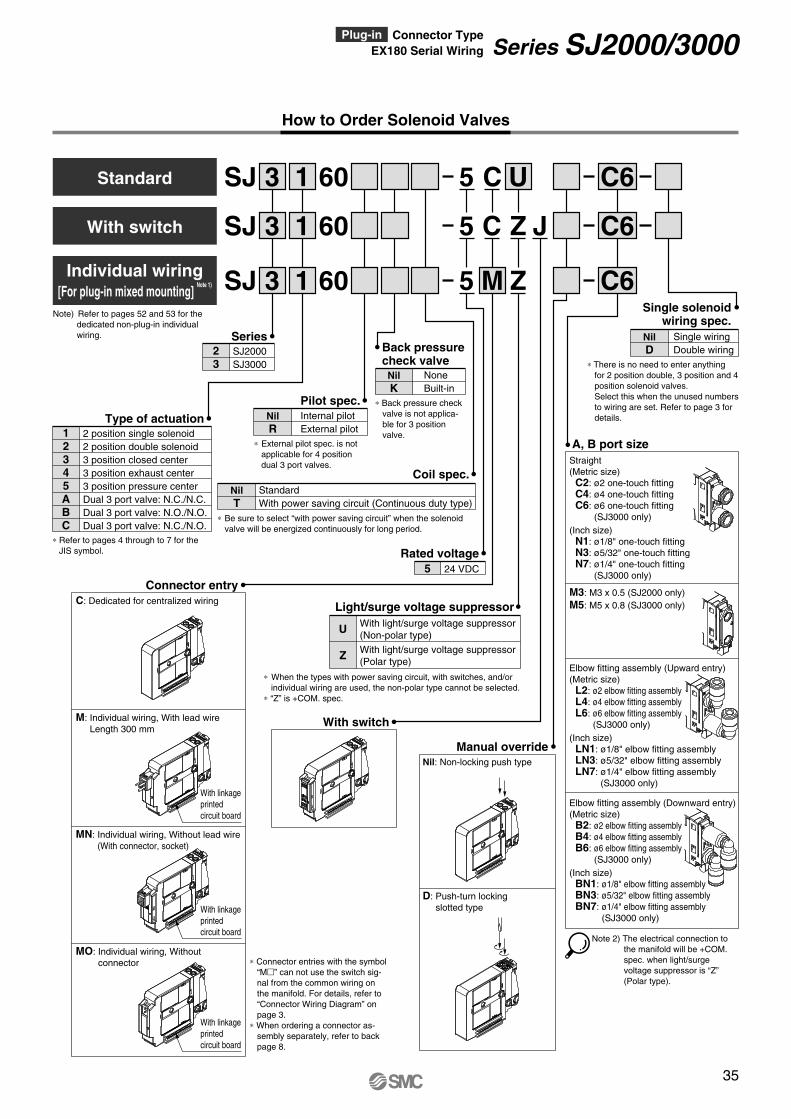
SJ 3 1 U60 C6
SJ 3
SJ 3 1 Z60 C6
1
5
5
5
C
M
C Z J60 C6
Internal pilot External pilot
Pilot spec.Nil R
∗ External pilot spec. is not applicable for 4 position dual 3 port valves.
None Built-in
Back pressure check valveNil K
∗ Back pressure check valve is not applica-ble for 3 position valve.2 position single solenoid
2 position double solenoid 3 position closed center 3 position exhaust center 3 position pressure center Dual 3 port valve: N.C./N.C. Dual 3 port valve: N.O./N.O. Dual 3 port valve: N.C./N.O.
Type of actuation12345ABC
∗ Refer to pages 4 through to 7 for the JIS symbol. Rated voltage
24 VDC5
Single wiring Double wiring
Single solenoid wiring spec.
Nil D
∗ There is no need to enter anything for 2 position double, 3 position and 4 position solenoid valves.Select this when the unused numbers to wiring are set. Refer to page 3 for details.
A, B port sizeStraight (Metric size) C2: ø2 one-touch fitting C4: ø4 one-touch fitting C6: ø6 one-touch fitting
(SJ3000 only) (Inch size) N1: ø1/8" one-touch fitting N3: ø5/32" one-touch fitting N7: ø1/4" one-touch fitting
(SJ3000 only)
M3: M3 x 0.5 (SJ2000 only) M5: M5 x 0.8 (SJ3000 only)
Elbow fitting assembly (Upward entry) (Metric size) L2: ø2 elbow fitting assembly L4: ø4 elbow fitting assembly
L6: ø6 elbow fitting assembly (SJ3000 only)
(Inch size) LN1: ø1/8" elbow fitting assembly LN3: ø5/32" elbow fitting assembly LN7: ø1/4" elbow fitting assembly
(SJ3000 only)
Elbow fitting assembly (Downward entry) (Metric size) B2: ø2 elbow fitting assembly B4: ø4 elbow fitting assembly B6: ø6 elbow fitting assembly
(SJ3000 only) (Inch size) BN1: ø1/8" elbow fitting assembly BN3: ø5/32" elbow fitting assembly BN7: ø1/4" elbow fitting assembly
(SJ3000 only)
SJ2000 SJ3000
23
Series
Manual overrideNil: Non-locking push type
D: Push-turn locking slotted type
With switch
Note 2) The electrical connection to the manifold will be +COM. spec. when light/surge voltage suppressor is “Z” (Polar type).
Connector entryC: Dedicated for centralized wiring
M: Individual wiring, With lead wire Length 300 mm
MN: Individual wiring, Without lead wire (With connector, socket)
MO: Individual wiring, Without connector
With linkage printed circuit board
With linkage printed circuit board
With linkage printed circuit board
With light/surge voltage suppressor (Non-polar type)
With light/surge voltage suppressor (Polar type)
Light/surge voltage suppressor
U
Z
∗ When the types with power saving circuit, with switches, and/or individual wiring are used, the non-polar type cannot be selected.
∗ “Z” is +COM. spec.
Coil spec.
Note) Refer to pages 52 and 53 for the dedicated non-plug-in individual wiring.
With switch
Individual wiring [For plug-in mixed mounting]
Note 1)
How to Order Solenoid Valves
Standard
∗ Connector entries with the symbol “Mm” can not use the switch sig-nal from the common wiring on the manifold. For details, refer to “Connector Wiring Diagram” on page 3.
∗ When ordering a connector as-sembly separately, refer to back page 8.
Standard With power saving circuit (Continuous duty type)
Nil T
∗ Be sure to select “with power saving circuit” when the solenoid valve will be energized continuously for long period.
35
Series SJ2000/3000EX180 Serial WiringPlug-in Connector Type

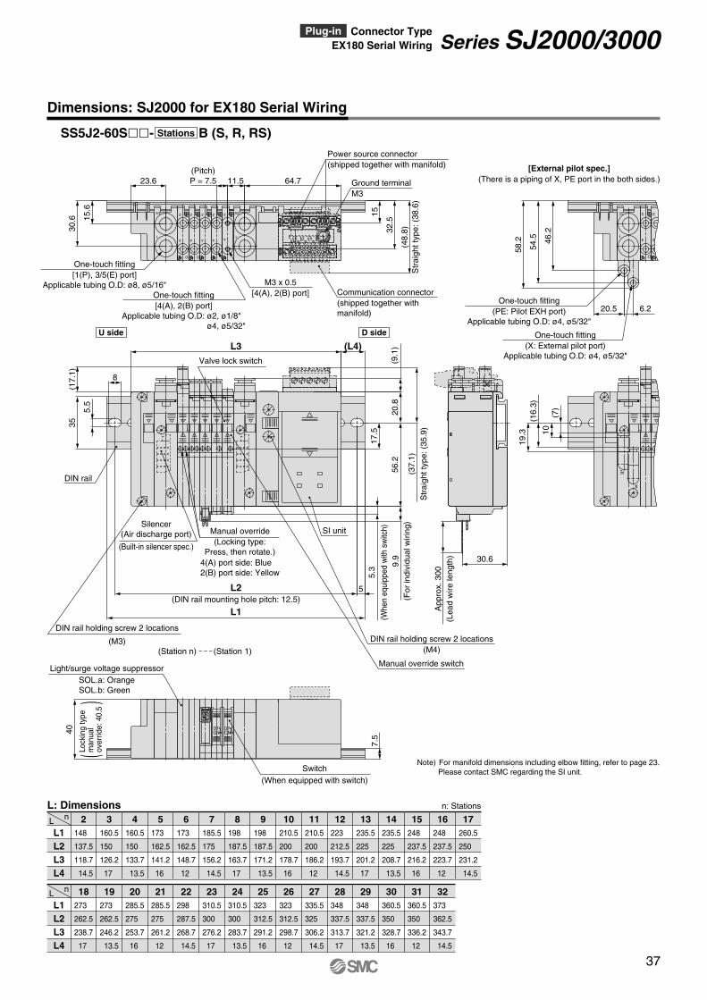
Dimensions: SJ2000 for EX180 Serial Wiring
L1 L2 L3 L4
2nL
L: Dimensions n: Stations
135.5
125
103.2
16
135.5
125
110.7
12.5
148
137.5
118.2
15
160.5
150
125.7
17.5
160.5
150
133.2
13.5
173
162.5
140.7
16
173
162.5
148.2
12.5
185.5
175
155.7
15
198
187.5
163.2
17.5
3 4 5 6 7 8 9 10
2
4
D
2
4
D
2
4 4
22
4
3/5
1
(48.
8)S
trai
ghtt
ype:
(38.
6)
32.5
15
11.5
15.6
23.6
30.6
Power source connector (shipped together with manifold)
Ground terminal M3
Communication connector (shipped together with manifold)
(Pitch) P = 7.5
One-touch fitting [4(A), 2(B) port]
Applicable tubing O.D: ø2, ø1/8" ø4, ø5/32"
M3 x 0.5 [4(A), 2(B) port]
One-touch fitting [1(P), 3/5(E) port]
Applicable tubing O.D: ø8, ø5/16"
Silencer (Air discharge port)
10
Str
aigh
ttyp
e:(3
5.9)
PE
X
3/5
1
BA
OFFON
OFFON
D
2
4
54.5
58.2 46
.2
19.3
(16.
3)
(7)
App
rox.
3009.
9 30.65.3
(17.
1)
(9.1
)
(8.6
)
(1.8
)
(37.
1)
6.220.5
8
(L4)
5
L1
L2
56.2
20.8
17.5
35
5.5
L3
40
7.5
One-touch fitting (PE: Pilot EXH port)
Applicable tubing O.D: ø4, ø5/32"
One-touch fitting (X: External pilot port)
Applicable tubing O.D: ø4, ø5/32"
(Whe
nequ
ipped
with
switc
h)
Switch (When equipped with switch)
(For
indi
vidu
alw
iring
)
(M4)
2
4
[External pilot spec.]
SI unit
DIN rail
SOL.a: Orange SOL.b: Green
Light/surge voltage suppressor
(DIN rail mounting hole pitch: 12.5)
(Lea
dw
irele
ngth
)
DIN rail holding screw 2 locations
(Built-in silencer spec.)
(M3)
DIN rail holding screw 2 locations
Valve lock switch
Manual override switch
SS5J2-60Sll- U (S, R, RS)Stations
U side D side
(Station n) (Station 1)
4(A) port side: Blue 2(B) port side: Yellow
Manual override (Locking type: Press, then rotate.)
()
Lock
ing
type
man
ual
over
ride:
40.5
Note) For manifold dimensions including elbow fitting, refer to page 23. Please contact SMC regarding the SI unit.
36
Series SJ2000/3000
Dimensions: SJ2000 for EX180 Serial Wiring
L1 L2 L3 L4
nL273
262.5
238.7
17
273
262.5
246.2
13.5
285.5
275
253.7
16
285.5
275
261.2
12
298
287.5
268.7
14.5
310.5
300
276.2
17
310.5
300
283.7
13.5
323
312.5
291.2
16
323
312.5
298.7
12
335.5
325
306.2
14.5
348
337.5
313.7
17
348
337.5
321.2
13.5
360.5
350
328.7
16
360.5
350
336.2
12
373
362.5
343.7
14.5
18 19 20 21 22 23 24 25 26 27 28 29 30 31 32
L1 L2 L3 L4
2nL
L: Dimensions n: Stations
148
137.5
118.7
14.5
160.5
150
126.2
17
160.5
150
133.7
13.5
173
162.5
141.2
16
173
162.5
148.7
12
185.5
175
156.2
14.5
198
187.5
163.7
17
198
187.5
171.2
13.5
210.5
200
178.7
16
210.5
200
186.2
12
223
212.5
193.7
14.5
235.5
225
201.2
17
235.5
225
208.7
13.5
248
237.5
216.2
16
248
237.5
223.7
12
260.5
250
231.2
14.5
3 4 5 6 7 8 9 10 11 12 13 14 15 16 17
2
4
D
2
4
D
2
4
3/5
14
22
4
3/5
1
(48.
8)S
trai
ghtt
ype:
(38.
6)
11.5 64.7
32.5
1515.6
23.6
30.6
Power source connector (shipped together with manifold)
Ground terminal M3
Communication connector (shipped together with manifold)
(Pitch) P = 7.5
One-touch fitting [4(A), 2(B) port]
Applicable tubing O.D: ø2, ø1/8" ø4, ø5/32"
M3 x 0.5 [4(A), 2(B) port]
One-touch fitting [1(P), 3/5(E) port]
Applicable tubing O.D: ø8, ø5/16"
DIN rail holding screw 2 locations
Silencer (Air discharge port) SI unit
PE
X
3/5
1
BA
OFFON
OFFON
D
2
4
54.5
58.2 46
.2
19.3
(16.
3)
10(7
)30.6
5.3
8
(17.
1)
(9.1
)
(37.
1)
6.220.5
(L4)L3
5
L1
L2
56.2
20.8
17.5
35
5.5
40
7.5
One-touch fitting (PE: Pilot EXH port)
Applicable tubing O.D: ø4, ø5/32"
(Whe
neq
uipp
edw
ithsw
itch)
(M4)DIN rail holding screw 2 locations
Str
aigh
ttyp
e:(3
5.9)
2
4
[External pilot spec.] (There is a piping of X, PE port in the both sides.)
(Built-in silencer spec.)
(M3)
Light/surge voltage suppressor
DIN rail
SOL.a: Orange SOL.b: Green
(DIN rail mounting hole pitch: 12.5)
One-touch fitting (X: External pilot port)
Applicable tubing O.D: ø4, ø5/32"
App
rox.
300
(Lea
dw
irele
ngth
)
9.9
(For
indi
vidu
alw
iring
)
Switch (When equipped with switch)
Valve lock switch
Manual override switch
SS5J2-60Sll- B (S, R, RS)Stations
U side D side
(Station n) (Station 1)
4(A) port side: Blue 2(B) port side: Yellow
Manual override (Locking type:
Press, then rotate.)
()
Lock
ing
type
man
ual
over
ride:
40.5
Note) For manifold dimensions including elbow fitting, refer to page 23. Please contact SMC regarding the SI unit.
37
Series SJ2000/3000EX180 Serial Wiring Plug-in Connector Type
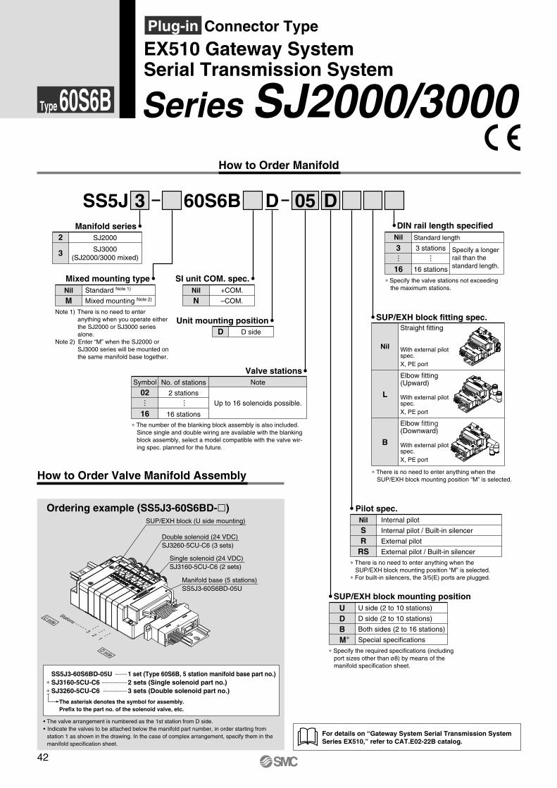
How to Order Manifold
Nil
N+COM.
–COM.
SI unit COM. spec.
2
3
SJ2000
SJ3000 (SJ2000/3000 mixed)
Manifold series
Unit mounting positionD D side
Nil
SR
RS
Pilot spec.Internal pilot
Internal pilot / Built-in silencer
External pilot
External pilot / Built-in silencer
Valve stations
∗ The number of the blanking block assembly is also included. Since single and double wiring are available with the blanking block assembly, select a model compatible with the valve wir-ing spec. planned for the future.
Symbol
02
16
No. of stations
2 stations
16 stations
Note
Up to 16 solenoids possible.
Mixed mounting typeNil
MStandard Note 1)
Mixed mounting Note 2)
Note 1) There is no need to enter anything when you operate either the SJ2000 or SJ3000 series alone.
Note 2) Enter “M” when the SJ2000 or SJ3000 series will be mounted on the same manifold base together.
SS5J 60S6B
How to Order Valve Manifold Assembly
3 D 05 D
Ordering example (SS5J3-60S6BD-l)
SUP/EXH block fitting spec.
Nil
Straight fitting
L
Elbow fitting (Upward)
B
Elbow fitting (Downward)
DIN rail length specified
Specify a longer rail than the standard length.
Standard length
3 stations
16 stations
Nil
3
16
With external pilot spec. X, PE port
With external pilot spec. X, PE port
With external pilot spec. X, PE port
∗ Specify the required specifications (including port sizes other than ø8) by means of the manifold specification sheet.
SUP/EXH block mounting positionUDBM∗
U side (2 to 10 stations)
D side (2 to 10 stations)
Both sides (2 to 16 stations)
Special specifications
∗ There is no need to enter anything when the SUP/EXH block mounting position “M” is selected.
∗ There is no need to enter anything when the SUP/EXH block mounting position “M” is selected.
∗ For built-in silencers, the 3/5(E) ports are plugged.Manifold base (5 stations) SS5J3-60S6BD-05U
Single solenoid (24 VDC) SJ3160-5CU-C6 (2 sets)
6
1514
7
01
COMPWB
Double solenoid (24 VDC) SJ3260-5CU-C6 (3 sets)
SUP/EXH block (U side mounting)
13
2
Type 60S6B
For details on “Gateway System Serial Transmission System Series EX510,” refer to CAT.E02-22B catalog.
∗ Specify the valve stations not exceeding the maximum stations.
Stations
D side
U side
Series SJ2000/3000EX510 Gateway System Serial Transmission System
Plug-in Connector Type
• The valve arrangement is numbered as the 1st station from D side.• Indicate the valves to be attached below the manifold part number, in order starting from
station 1 as shown in the drawing. In the case of complex arrangement, specify them in themanifold specification sheet.
The asterisk denotes the symbol for assembly. Prefix to the part no. of the solenoid valve, etc.
SS5J3-60S6BD-05U 1 set (Type 60S6B, 5 station manifold base part no.) ∗ SJ3160-5CU-C6 2 sets (Single solenoid part no.) ∗ SJ3260-5CU-C6 3 sets (Double solenoid part no.)
42

SJ 3 1 U60 C6
SJ 3
SJ 3 1 Z60 C6
1
5
5
5
C
M
C Z60 C6
SeriesSJ2000
SJ3000
23
Type of actuation2 position single solenoid
2 position double solenoid
3 position closed center
3 position exhaust center
3 position pressure center
Dual 3 port valve: N.C./N.C.
Dual 3 port valve: N.O./N.O.
Dual 3 port valve: N.C./N.O.
12345ABC
None
Built-in
Nil
K
Back pressure check valve
∗ Back pressure check valve is not applica-ble for 3 position valve.
24 VDC5Rated voltage
Note 2) The electrical connection to the manifold will be +COM. spec. when light/surge voltage suppressor is “Z” (Polar type).
Single wiring
Double wiring
Nil
D
Single solenoid wiring spec.
∗ There is no need to enter anything for 2 position double, 3 position and 4 position solenoid valves.Select this when the unused numbers to wiring are set. Refer to page 3 for details.
Manual overrideNil: Non-locking push type
D: Push-turn locking slotted type
A, B port sizeStraight (Metric size) C2: ø2 one-touch fitting C4: ø4 one-touch fitting C6: ø6 one-touch fitting
(SJ3000 only) (Inch size) N1: ø1/8" one-touch fitting N3: ø5/32" one-touch fitting N7: ø1/4" one-touch fitting
(SJ3000 only)
M3: M3 x 0.5 (SJ2000 only) M5: M5 x 0.8 (SJ3000 only)
Elbow fitting assembly (Upward entry) (Metric size) L2: ø2 elbow fitting assembly L4: ø4 elbow fitting assembly
L6: ø6 elbow fitting assembly (SJ3000 only)
(Inch size) LN1: ø1/8" elbow fitting assembly LN3: ø5/32" elbow fitting assembly LN7: ø1/4" elbow fitting assembly
(SJ3000 only)
Elbow fitting assembly (Downward entry) (Metric size) B2: ø2 elbow fitting assembly B4: ø4 elbow fitting assembly B6: ø6 elbow fitting assembly
(SJ3000 only) (Inch size) BN1: ø1/8" elbow fitting assembly BN3: ø5/32" elbow fitting assembly BN7: ø1/4" elbow fitting assembly
(SJ3000 only)
Pilot spec.
∗ External pilot spec. is not applicable for 4 position dual 3 port valves.
Internal pilot
External pilot
Nil
R
J
With switch
∗ Refer to pages 4 through to 7 for the JIS symbol.
Connector entryC: Dedicated for centralized wiring
M: Individual wiring, With lead wire Length 300 mm
MN: Individual wiring, Without lead wire
MO: Individual wiring, Without connector
With linkage printed circuit board
With linkage printed circuit board
With linkage printed circuit board
With light/surge voltage suppressor (Non-polar type)
With light/surge voltage suppressor (Polar type)
Light/surge voltage suppressor
U
Z
∗ When the types with power saving circuit, with switches, and individual wiring are used, the non-polar type cannot be selected.
∗ “Z” is +COM. spec. ∗ When –COM of SI unit common specifications is used, select the
non-polar type.
Coil spec.
How to Order Solenoid Valves
Note) Refer to pages 52 and 53 for the dedicated non-plug-in individual wiring.
With switch
Individual wiring [For plug-in mixed mounting]
Note 1)
Standard
Standard With power saving circuit (Continuous duty type)
Nil T
∗ Be sure to select “with power saving circuit” when the solenoid valve will be energized continuously for long period.
∗ Connector entries with the symbol “Mm” can not use the switch sig-nal from the common wiring on the manifold. For details, refer to “Connector Wiring Diagram” on page 3.
∗ When ordering a connector as-sembly separately, refer to back page 8.
43
Series SJ2000/3000EX510 Gateway System Serial Transmission SystemPlug-in Connector Type
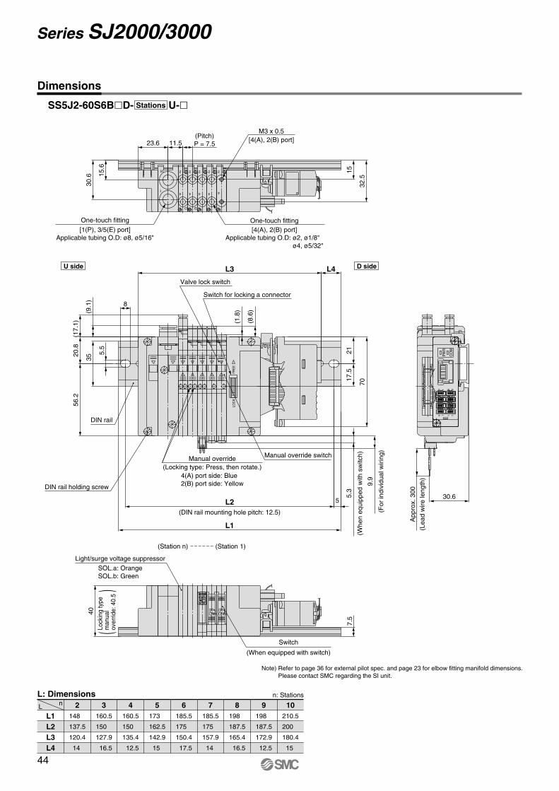
Dimensions
n: Stations
L nL: Dimensions
L1 L2 L3 L4
2148
137.5
120.4
14
3160.5
150
127.9
16.5
4160.5
150
135.4
12.5
5173
162.5
142.9
15
6185.5
175
150.4
17.5
7185.5
175
157.9
14
8198
187.5
165.4
16.5
9198
187.5
172.9
12.5
10210.5
200
180.4
15
BA
FRE
ELO
CK
8 90 1
151476
PWR
COM
2
4
D
2
4
D
2
4 4
22
4
3/5
1
OFFON
OFFON
(When equipped with switch)
Switch
30.6
App
rox.
300
9.9
5.3
17.5
L3
56.2
(8.6
)
(1.8
)
(17.
1)20
.8
(9.1
)
70
21
5
L4
7.5
L1
L2
8
35
5.5
11.5
32.5
1515.6
23.6
4030
.6
(Lea
dw
irele
ngth
)
(For
indi
vidu
alw
iring
)
Valve lock switch
Manual override switch
(Whe
neq
uipp
edw
ithsw
itch)
(Pitch) P = 7.5
Applicable tubing O.D: ø2, ø1/8" ø4, ø5/32"
One-touch fitting
[4(A), 2(B) port]M3 x 0.5
[1(P), 3/5(E) port] Applicable tubing O.D: ø8, ø5/16"
One-touch fitting
DIN rail holding screw
DIN rail
SOL.a: Orange SOL.b: Green
(DIN rail mounting hole pitch: 12.5)
[4(A), 2(B) port]
Light/surge voltage suppressor
Switch for locking a connector
SS5J2-60S6BlD- U-lStations
U side D side
(Station n) (Station 1)
4(A) port side: Blue 2(B) port side: Yellow
Manual override (Locking type: Press, then rotate.)
()
Lock
ing
type
man
ual
over
ride:
40.5
Note) Refer to page 36 for external pilot spec. and page 23 for elbow fitting manifold dimensions. Please contact SMC regarding the SI unit.
44
Series SJ2000/3000
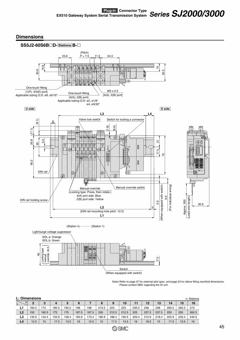
Dimensions
n: Stations
L nL: Dimensions
L1 L2 L3 L4
2160.5
150
135.9
12.5
3173
162.5
143.4
15
4185.5
175
150.9
17.5
5185.5
175
158.4
13.5
6198
187.5
165.9
16
7198
187.5
173.4
12.5
8210.5
200
180.9
15
9223
212.5
188.4
17.5
10223
212.5
195.9
13.5
11235.5
225
203.4
16
12248
237.5
210.9
18.5
13248
237.5
218.4
15
14260.5
250
225.9
17.5
15260.5
250
233.4
13.5
16273
262.5
240.9
16
SS5J2-60S6BlD- B-lStations
8 90 1
151476
PWR
COM
OFFON
OFFON
BA
FRE
ELO
CK
30.6
App
rox.
300
5.3
9.9
70
17.5
(8.6
)
(1.8
)
L3
56.2
(17.
1)20
.8
(9.1
)
21
5
L4
7.5
L1
L2
8
35
5.5
40
(Lea
dw
irele
ngth
)
(Whe
neq
uipp
edw
ithsw
itch)
(For
indi
vidu
alw
iring
)
(When equipped with switch)Switch
Valve lock switch
Manual override switch
DIN rail holding screw
DIN rail
SOL.a: Orange SOL.b: Green
Light/surge voltage suppressor
(DIN rail mounting hole pitch: 12.5)
11.5 34.3
32.5
1515.6
23.6
30.6
(Pitch) P = 7.5
[4(A), 2(B) port] Applicable tubing O.D: ø2, ø1/8"
ø4, ø5/32"
One-touch fitting
[4(A), 2(B) port]
M3 x 0.5[1(P), 3/5(E) port] Applicable tubing O.D: ø8, ø5/16"
One-touch fitting
3/5
1
2
4
D
2
4
D
2
4 4
22
4
3/5
1
Note) Refer to page 37 for external pilot spec. and page 23 for elbow fitting manifold dimensions. Please contact SMC regarding the SI unit.
Switch for locking a connector
U side D side
(Station n) (Station 1)
()
Lock
ing
type
man
ual
over
ride:
40.5
4(A) port side: Blue 2(B) port side: Yellow
Manual override (Locking type: Press, then rotate.)
45
Series SJ2000/3000EX510 Gateway System Serial Transmission System Plug-in Connector Type
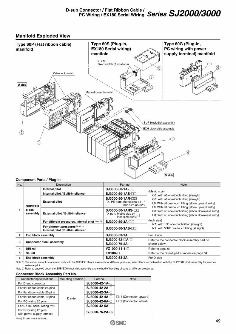
Type 60P (Flat ribbon cable) manifold
Manifold Exploded View
r
e
w
q
EXH block disk assembly
SUP block disk assembly
U side
D side
Manual override switch
Valve lock switch
t
e
SI unit Fixed switch (2 locations)
Type 60G (Plug-in, PC wiring with power supply terminal) manifold
ey
Type 60S (Plug-in, EX180 Serial wiring) manifold
Connector Block Assembly Part No.
For D-sub connector
For flat ribbon cable 26 pins
For flat ribbon cable 20 pins
For flat ribbon cable 10 pins
For PC wiring 20 pins
For EX180 serial wiring Note)
For PC wiring 20 pins with power supply terminal
D side
SJ3000-42-1A-lSJ3000-42-2A-lSJ3000-42-3A-lSJ3000-42-4A-lSJ3000-42-6A-lSJ3000-42-5A
SJ3000-76-2A-05
m: 1 (Connector upward)
m: 2 (Connector lateral)
NoteConnector specifications Mounting position Part no.
Component Parts / Plug-in
1
2
3
4
5
6
SUP/EXH block assembly
End block assembly
Connector block assembly
DIN rail
SI unit
End block assembly
Internal pilot
Internal pilot / Built-in silencer
External pilot
External pilot / Built-in silencer
For different pressures, internal pilot Note 1)
For different pressures Note 1) Internal pilot / Built-in silencer
SJ3000-50-1A-ll
SJ3000-50-1AS-llSJ3000-50-1AR-ll
X, PE port: Metric size ø4 Inch size ø5/32"
SJ3000-50-1ARS-llX port: Metric size ø4
Inch size ø5/32"
SJ3000-50-3A-ll
SJ3000-50-3AS-ll
SJ3000-53-1A SJ3000-42-lA-lSJ3000-76-2A-lVZ1000-11-1-lEX180-ll
SJ3000-53-2A
(Metric size) C6: With ø6 one-touch fitting (straight) C8: With ø8 one-touch fitting (straight) L6: With ø6 one-touch fitting (elbow upward entry) L8: With ø8 one-touch fitting (elbow upward entry) B6: With ø6 one-touch fitting (elbow downward entry) B8: With ø8 one-touch fitting (elbow downward entry)
(Inch size) N7: With 1/4" one-touch fitting (straight) N9: With 5/16" one-touch fitting (straight)
For U side
Refer to page 61.
Refer to the SI unit part numbers on page 34.
For D side
Refer to the connector block assembly part no. shown below.
NotePart no.DescriptionNo.
Note) SI unit is not included.
Note 1) The valves cannot be operated only with the SUP/EXH block assembly for different pressure, select them in combination with the SUP/EXH block assembly for internal/external pilot.
Note 2) Refer to page 60 about the SUP/EXH block disk assembly and method of handling of parts at different pressures.
49
Series SJ2000/3000D-sub Connector / Flat Ribbon Cable / PC Wiring / EX180 Serial Wiring
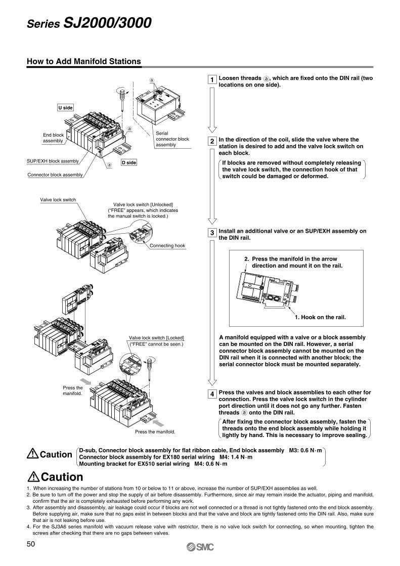
How to Add Manifold Stations
Press the valves and block assemblies to each other for connection. Press the valve lock switch in the cylinder port direction until it does not go any further. Fasten threads onto the DIN rail.
4
Loosen threads , which are fixed onto the DIN rail (two locations on one side).
1
In the direction of the coil, slide the valve where the station is desired to add and the valve lock switch on each block.
If blocks are removed without completely releasing the valve lock switch, the connection hook of that switch could be damaged or deformed.
2
Install an additional valve or an SUP/EXH assembly on the DIN rail.
A manifold equipped with a valve or a block assembly can be mounted on the DIN rail. However, a serial connector block assembly cannot be mounted on the DIN rail when it is connected with another block; the serial connector block must be mounted separately.
3
(“FREE” cannot be seen.)Valve lock switch [Locked]
Press the manifold.
Press the manifold.
Connector block assembly
End block assembly
SUP/EXH block assembly
Connecting hook
Valve lock switch [Unlocked]Valve lock switch
(“FREE” appears, which indicates the manual switch is locked.)
1. Hook on the rail.
Serial connector block assembly
1. When increasing the number of stations from 10 or below to 11 or above, increase the number of SUP/EXH assemblies as well. 2. Be sure to turn off the power and stop the supply of air before disassembly. Furthermore, since air may remain inside the actuator, piping and manifold,
confirm that the air is completely exhausted before performing any work. 3. After assembly and disassembly, air leakage could occur if blocks are not well connected or a thread is not tightly fastened onto the end block assembly.
Before supplying air, make sure that no gaps exist in between blocks and that the valve and block are tightly fastened onto the DIN rail. Also, make sure that air is not leaking before use.
4. For the SJ3A6 series manifold with vacuum release valve with restrictor, there is no valve lock switch for connecting, so when mounting, tighten the screws after checking that there are no gaps between valves.
Caution
CautionD-sub, Connector block assembly for flat ribbon cable, End block assembly M3: 0.6 N·m Connector block assembly for EX180 serial wiring M4: 1.4 N·m Mounting bracket for EX510 serial wiring M4: 0.6 N·m
U side
D side
After fixing the connector block assembly, fasten the threads onto the end block assembly while holding it lightly by hand. This is necessary to improve sealing.
2. Press the manifold in the arrow direction and mount it on the rail.
50
Series SJ2000/3000
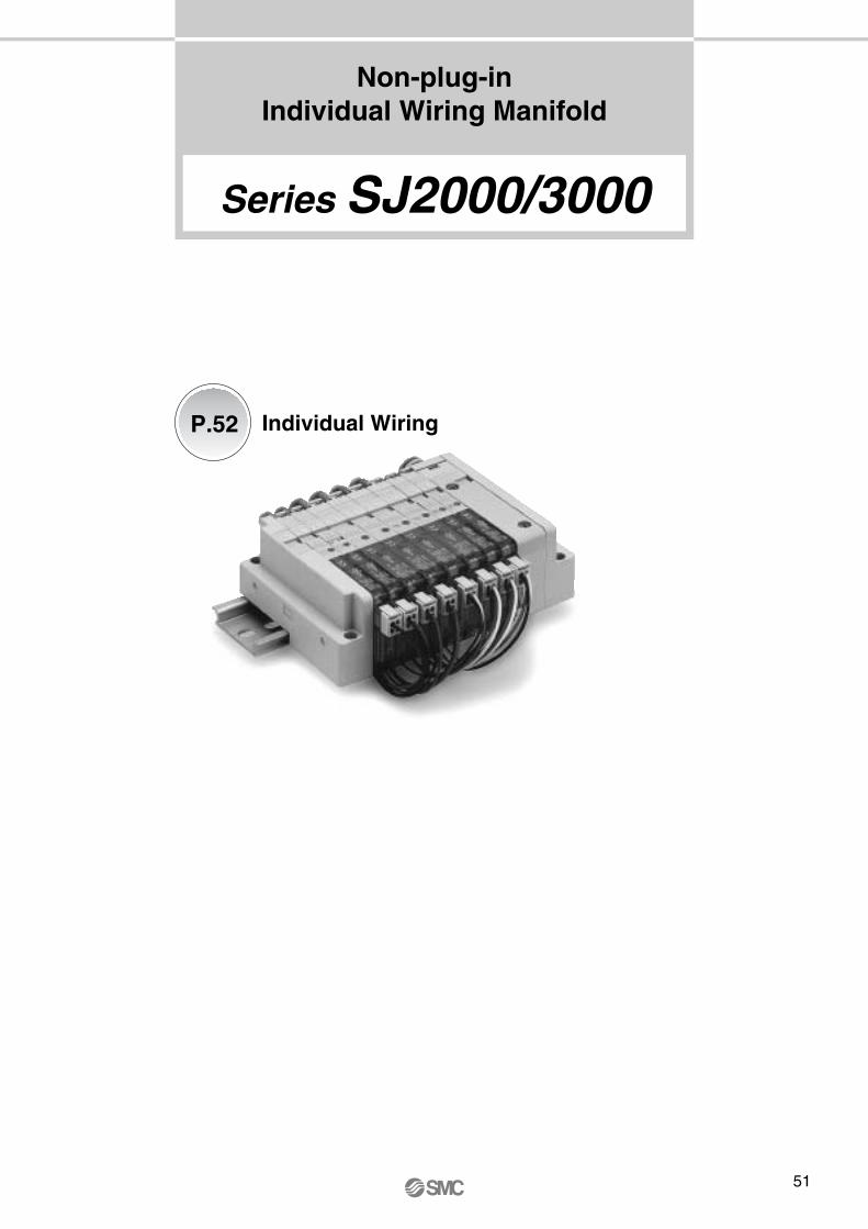
Non-plug-in Individual Wiring Manifold
Individual WiringP.52
Series SJ2000/3000
51
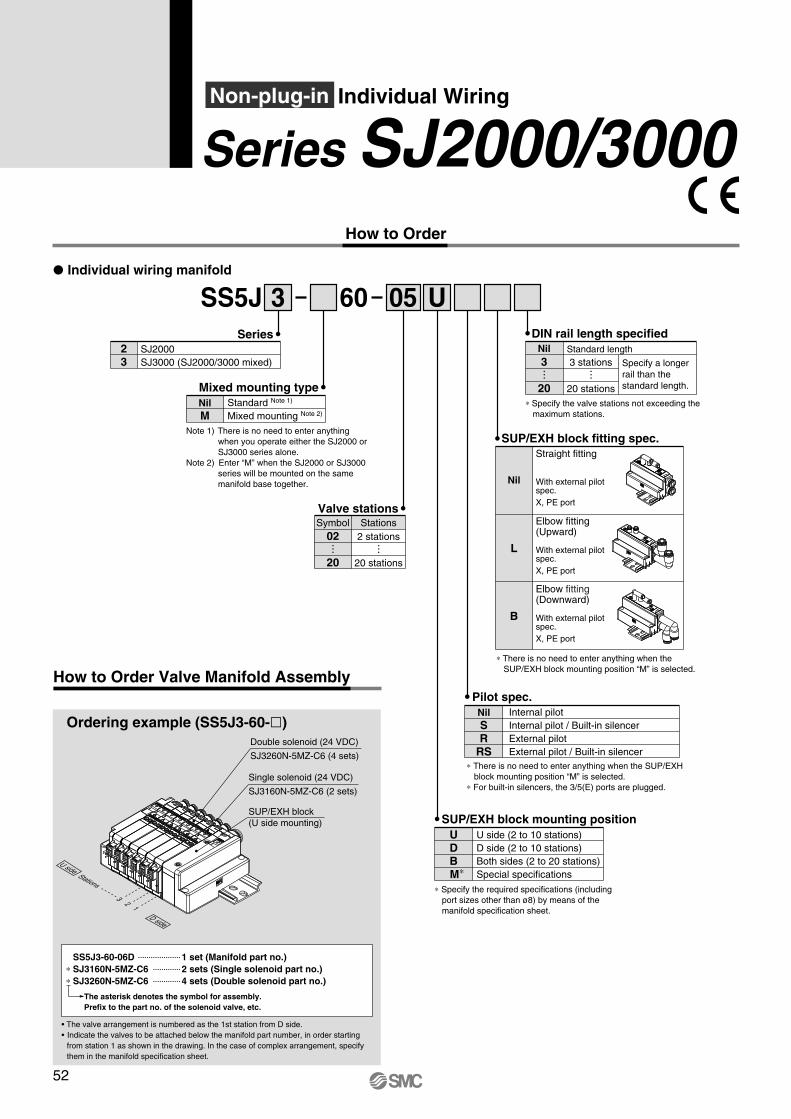
How to Order Valve Manifold Assembly
Ordering example (SS5J3-60-l)
60 U
Series SJ2000/3000How to Order
SS5J 3P Individual wiring manifold
SeriesSJ2000 SJ3000 (SJ2000/3000 mixed)
23
05
Mixed mounting typeNil M
Note 1) There is no need to enter anything when you operate either the SJ2000 or SJ3000 series alone.
Note 2) Enter “M” when the SJ2000 or SJ3000 series will be mounted on the same manifold base together.
Standard Note 1)
Mixed mounting Note 2)
Valve stations
2 stations
20 stations
Symbol Stations02
20
∗ Specify the required specifications (including port sizes other than ø8) by means of the manifold specification sheet.
SUP/EXH block mounting positionUDBM∗
U side (2 to 10 stations) D side (2 to 10 stations) Both sides (2 to 20 stations) Special specifications
Internal pilot Internal pilot / Built-in silencer External pilot External pilot / Built-in silencer
Pilot spec.Nil SR
RS
SUP/EXH block fitting spec.
Nil
Straight fitting
L
Elbow fitting (Upward)
B
Elbow fitting (Downward)
With external pilot spec. X, PE port
With external pilot spec. X, PE port
With external pilot spec. X, PE port
Double solenoid (24 VDC)
SJ3260N-5MZ-C6 (4 sets)
Single solenoid (24 VDC)
SJ3160N-5MZ-C6 (2 sets)
SUP/EXH block (U side mounting)
13
2
∗ There is no need to enter anything when the SUP/EXH block mounting position “M” is selected.
DIN rail length specified
Specify a longer rail than the standard length.
Standard length3 stations
20 stations
Nil3
20∗ Specify the valve stations not exceeding the
maximum stations.
Stations
U side
D side
Non-plug-in Individual Wiring
∗ There is no need to enter anything when the SUP/EXH block mounting position “M” is selected.
∗ For built-in silencers, the 3/5(E) ports are plugged.
• The valve arrangement is numbered as the 1st station from D side.• Indicate the valves to be attached below the manifold part number, in order starting
from station 1 as shown in the drawing. In the case of complex arrangement, specify them in the manifold specification sheet.
The asterisk denotes the symbol for assembly. Prefix to the part no. of the solenoid valve, etc.
SS5J3-60-06D 1 set (Manifold part no.) ∗ SJ3160N-5MZ-C6 2 sets (Single solenoid part no.) ∗ SJ3260N-5MZ-C6 4 sets (Double solenoid part no.)
52
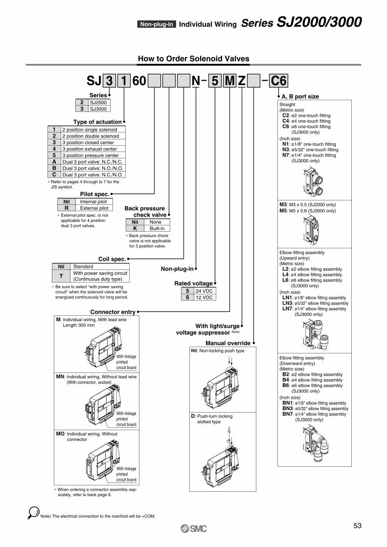
SeriesSJ2000 SJ3000
23
Internal pilot External pilot
Pilot spec.Nil R
∗ External pilot spec. is not applicable for 4 position dual 3 port valves.
None Built-in
Back pressure check valve
Nil K
∗ Back pressure check valve is not applicable for 3 position valve.
Rated voltage24 VDC 12 VDC
56
Note) The electrical connection to the manifold will be +COM.
SJ 60 N3 1 5 M Z C6
2 position single solenoid 2 position double solenoid 3 position closed center 3 position exhaust center 3 position pressure center Dual 3 port valve: N.C./N.C. Dual 3 port valve: N.O./N.O. Dual 3 port valve: N.C./N.O.
Type of actuation12345ABC
∗ Refer to pages 4 through to 7 for the JIS symbol.
With light/surge voltage suppressor Note)
Non-plug-in
A, B port sizeStraight (Metric size) C2: ø2 one-touch fitting C4: ø4 one-touch fitting C6: ø6 one-touch fitting
(SJ3000 only) (Inch size) N1: ø1/8" one-touch fitting N3: ø5/32" one-touch fitting N7: ø1/4" one-touch fitting
(SJ3000 only)
M3: M3 x 0.5 (SJ2000 only) M5: M5 x 0.8 (SJ3000 only)
Elbow fitting assembly (Upward entry) (Metric size) L2: ø2 elbow fitting assembly L4: ø4 elbow fitting assembly L6: ø6 elbow fitting assembly
(SJ3000 only) (Inch size) LN1: ø1/8" elbow fitting assembly LN3: ø5/32" elbow fitting assembly LN7: ø1/4" elbow fitting assembly
(SJ3000 only)
Elbow fitting assembly (Downward entry) (Metric size) B2: ø2 elbow fitting assembly B4: ø4 elbow fitting assembly B6: ø6 elbow fitting assembly
(SJ3000 only) (Inch size) BN1: ø1/8" elbow fitting assembly BN3: ø5/32" elbow fitting assembly BN7: ø1/4" elbow fitting assembly
(SJ3000 only)
Manual overrideNil: Non-locking push type
D: Push-turn locking slotted type
∗ When ordering a connector assembly sep-arately, refer to back page 8.
Connector entryM: Individual wiring, With lead wire
Length 300 mm
MN: Individual wiring, Without lead wire (With connector, socket)
MO: Individual wiring, Without connector
With linkage printed circuit board
With linkage printed circuit board
With linkage printed circuit board
StandardWith power saving circuit (Continuous duty type)
Coil spec.Nil
T
∗ Be sure to select “with power saving circuit” when the solenoid valve will be energized continuously for long period.
How to Order Solenoid Valves
53
Non-plug-in Individual Wiring Series SJ2000/3000
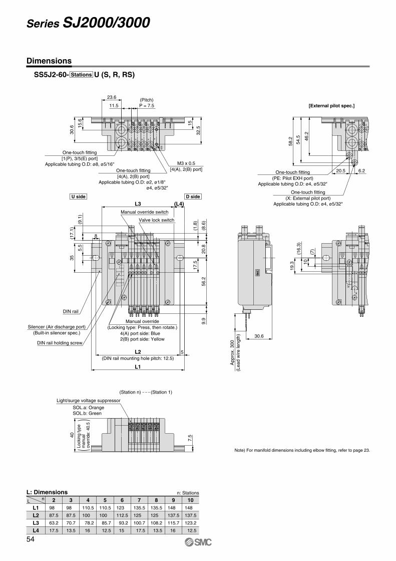
D
2
4
D
2
4
D
2
4 4
22
4
3/5
1
11.5
32.5
1515.6
23.6
30.6
One-touch fitting [1(P), 3/5(E) port]
Applicable tubing O.D: ø8, ø5/16"One-touch fitting [4(A), 2(B) port]
Applicable tubing O.D: ø2, ø1/8" ø4, ø5/32"
M3 x 0.5 [4(A), 2(B) port]
(Pitch) P = 7.5
3/5
1
D
2
4
2
4
58.2
54.5 46
.2
6.220.5
[External pilot spec.]
One-touch fitting (PE: Pilot EXH port)
Applicable tubing O.D: ø4, ø5/32"
One-touch fitting (X: External pilot port)
Applicable tubing O.D: ø4, ø5/32"
PE
X
BA
19.3
(16.
3)10
(7)
30.6
App
rox.
300
(Lea
dw
irele
ngth
)
BA BA BABABA
L3 (L4)9.
9
(17.
1)
(9.1
)
(8.6
)
(1.8
)
8
5.5
5
L1
L2
U side D side56
.2
17.5
20.8
35
Manual override switch
Valve lock switch
Silencer (Air discharge port) (Built-in silencer spec.)
DIN rail holding screw
DIN rail
(DIN rail mounting hole pitch: 12.5)
(Station 1)(Station n)
40
7.5
Light/surge voltage suppressor
Note) For manifold dimensions including elbow fitting, refer to page 23.
SOL.a: Orange SOL.b: Green
4(A) port side: Blue 2(B) port side: Yellow
Manual override (Locking type: Press, then rotate.)
()
Lock
ing
type
man
ual
over
ride:
40.5
54
Series SJ2000/3000
Dimensions
n: Stations
L nL: Dimensions
L1 L2 L3 L4
298
87.5
63.2
17.5
98
87.5
70.7
13.5
110.5
100
78.2
16
110.5
100
85.7
12.5
123
112.5
93.2
15
135.5
125
100.7
17.5
135.5
125
108.2
13.5
148
137.5
115.7
16
148
137.5
123.2
12.5
3 4 5 6 7 8 9 10
SS5J2-60- U (S, R, RS)Stations
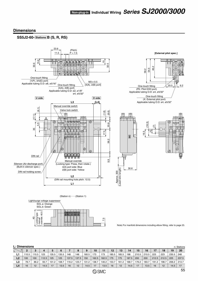
D
2
4
3/5
1
D
2
4
D
2
4 4
22
4
3/5
1
11.5
32.5
1515.6
23.6(Pitch) P = 7.5
30.6
One-touch fitting [1(P), 3/5(E) port]
Applicable tubing O.D: ø8, ø5/16"One-touch fitting [4(A), 2(B) port]
Applicable tubing O.D: ø2, ø1/8" ø4, ø5/32"
M3 x 0.5 [4(A), 2(B) port]
3/5
1
D
2
4
2
4
58.2
54.5 46
.2
6.220.5
[External pilot spec.]
One-touch fitting (PE: Pilot EXH port)
Applicable tubing O.D: ø4, ø5/32"
One-touch fitting (X: External pilot port)
Applicable tubing O.D: ø4, ø5/32"
PE
X
BA
19.3
(16.
3)10
(7)
30.6
App
rox.
300
(Lea
dw
irele
ngth
)
BA BA BABABA
(L4)L3
9.9
(17.
1)
(9.1
)
(8.6
)
(1.8
)
8
5.5
5
L1
L2
56.2
17.5
20.8
35
Valve lock switch
Manual override switch
DIN rail
Silencer (Air discharge port) (Built-in silencer spec.)
DIN rail holding screw
(DIN rail mounting hole pitch: 12.5)
40
7.5
Light/surge voltage suppressor
Note) For manifold dimensions including elbow fitting, refer to page 23.
U side D side
(Station 1)(Station n)
SOL.a: Orange SOL.b: Green
55
Dimensions
n: Stations
L nL: Dimensions
L1 L2 L3 L4
2110.5
100
78.7
16
110.5
100
86.2
12
123
112.5
93.7
14.5
135.5
125
101.2
17
135.5
125
108.7
13.5
148
137.5
116.2
16
148
137.5
123.7
12
160.5
150
131.2
14.5
173
162.5
138.7
17
173
162.5
146.2
13.5
185.5
175
153.7
16
185.5
175
161.2
12
198
187.5
168.7
14.5
210.5
200
176.2
17
210.5
200
183.7
13.5
223
212.5
191.2
16
223
212.5
198.7
12
235.5
225
206.2
14.5
248
237.5
213.7
17
3 4 5 6 7 8 9 10 11 12 13 14 15 16 20191817
SS5J2-60- B (S, R, RS)Stations
Non-plug-in Individual Wiring Series SJ2000/3000
()
Lock
ing
type
man
ual
over
ride:
40.5
4(A) port side: Blue 2(B) port side: Yellow
Manual override (Locking type: Press, then rotate.)
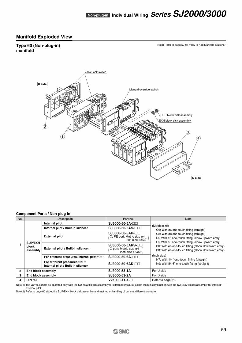
Component Parts / Non-plug-in
1
2
3
4
SUP/EXH block assembly
End block assembly
End block assembly
DIN rail
Internal pilot
Internal pilot / Built-in silencer
External pilot
External pilot / Built-in silencer
For different pressures, internal pilot Note 1)
For different pressures Note 1) Internal pilot / Built-in silencer
SJ3000-50-5A-ll SJ3000-50-5AS-llSJ3000-50-5AR-ll
X, PE port: Metric size ø4 Inch size ø5/32"
SJ3000-50-5ARS-llX port: Metric size ø4
Inch size ø5/32"
SJ3000-50-6A-ll
SJ3000-50-6AS-ll
SJ3000-53-1A SJ3000-53-2A VZ1000-11-1-l
(Metric size) C6: With ø6 one-touch fitting (straight) C8: With ø8 one-touch fitting (straight) L6: With ø6 one-touch fitting (elbow upward entry) L8: With ø8 one-touch fitting (elbow upward entry) B6: With ø6 one-touch fitting (elbow downward entry) B8: With ø8 one-touch fitting (elbow downward entry)
(Inch size) N7: With 1/4" one-touch fitting (straight) N9: With 5/16" one-touch fitting (straight)
For U side
For D side
Refer to page 61.
NotePart no.DescriptionNo.
Note) Refer to page 50 for “How to Add Manifold Stations.”
Note 1) The valves cannot be operated only with the SUP/EXH block assembly for different pressure, select them in combination with the SUP/EXH block assembly for internal/external pilot.
Note 2) Refer to page 60 about the SUP/EXH block disk assembly and method of handling of parts at different pressure.
w
q r
e
SUP block disk assembly
EXH block disk assembly
Valve lock switch
Manual override switch
U side
D side
59
Manifold Exploded View
Type 60 (Non-plug-in) manifold
Non-plug-in Individual Wiring Series SJ2000/3000
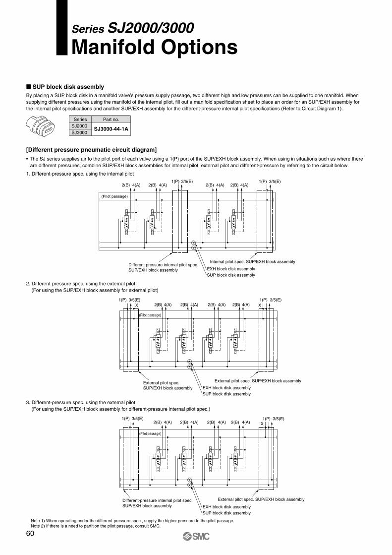
M SUP block disk assembly By placing a SUP block disk in a manifold valve’s pressure supply passage, two different high and low pressures can be supplied to one manifold. When supplying different pressures using the manifold of the internal pilot, fill out a manifold specification sheet to place an order for an SUP/EXH assembly for the internal pilot specifications and another SUP/EXH assembly for the different-pressure internal pilot specifications (Refer to Circuit Diagram 1).
SJ3000-44-1A
Series Part no.SJ2000 SJ3000
[Different pressure pneumatic circuit diagram]
Note 1) When operating under the different-pressure spec., supply the higher pressure to the pilot passage. Note 2) If there is a need to partition the pilot passage, consult SMC.
• The SJ series supplies air to the pilot port of each valve using a 1(P) port of the SUP/EXH block assembly. When using in situations such as where there are different pressures, combine SUP/EXH block assemblies for internal pilot, external pilot and different-pressure by referring to the circuit below.
2. Different-pressure spec. using the external pilot (For using the SUP/EXH block assembly for external pilot)
3. Different-pressure spec. using the external pilot (For using the SUP/EXH block assembly for different-pressure internal pilot spec.)
1. Different-pressure spec. using the internal pilot
3/5(E)1(P)X
X
Different-pressure internal pilot spec. SUP/EXH block assembly
SUP block disk assemblyEXH block disk assembly
External pilot spec. SUP/EXH block assembly
X
EXH block disk assemblySUP block disk assembly
External pilot spec. SUP/EXH block assembly External pilot spec. SUP/EXH block assembly
(Pilot passage)
**
4(A)2(B)4(A)2(B) 4(A)2(B)4(A)2(B)3/5(E)1(P)
(Pilot passage)
**
3/5(E)1(P)4(A)2(B)4(A)2(B) 4(A)2(B)4(A)2(B)
3/5(E)1(P)
3/5(E)1(P)
Internal pilot spec. SUP/EXH block assembly Different pressure internal pilot spec. SUP/EXH block assembly EXH block disk assembly
SUP block disk assembly
(Pilot passage)
**
3/5(E)1(P)4(A)2(B)4(A)2(B) 4(A)2(B)4(A)2(B)
Series SJ2000/3000Manifold Options
60
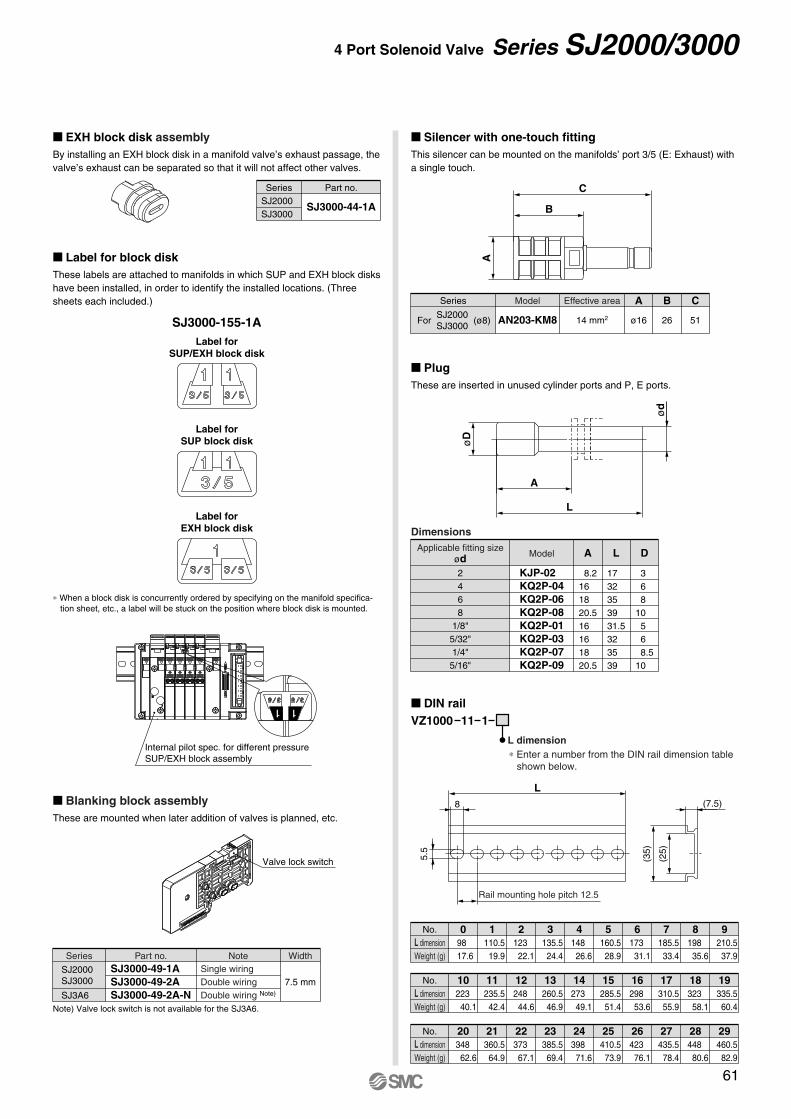
M Plug These are inserted in unused cylinder ports and P, E ports.
L
øD
A
ød
KJP-02 KQ2P-04 KQ2P-06 KQ2P-08 KQ2P-01 KQ2P-03 KQ2P-07 KQ2P-09
2468
1/8" 5/32" 1/4"
5/16"
Applicable fitting size ød
Dimensions
Model
8.2 16 18 20.5 16 16 18 20.5
A
17 32 35 39 31.5 32 35 39
L
368
10 568.5
10
D
M Silencer with one-touch fitting This silencer can be mounted on the manifolds’ port 3/5 (E: Exhaust) with a single touch.
A
C
B
(ø8)ForSJ2000 SJ3000
Series
14 mm2
Effective area
ø16
A
26
B
51
C
AN203-KM8
Model
M EXH block disk assembly By installing an EXH block disk in a manifold valve’s exhaust passage, the valve’s exhaust can be separated so that it will not affect other valves.
M Label for block disk These labels are attached to manifolds in which SUP and EXH block disks have been installed, in order to identify the installed locations. (Three sheets each included.)
∗ When a block disk is concurrently ordered by specifying on the manifold specifica-tion sheet, etc., a label will be stuck on the position where block disk is mounted.
SJ3000-44-1A
Series Part no.SJ2000 SJ3000
SJ3000-155-1ALabel for
SUP/EXH block disk
Label for EXH block disk
Label for SUP block disk
Internal pilot spec. for different pressure SUP/EXH block assembly
M Blanking block assembly These are mounted when later addition of valves is planned, etc.
Valve lock switch
SJ3000-49-1A SJ3000-49-2A SJ3000-49-2A-N
SJ2000 SJ3000
SJ3A6
Part no.Series Note Width
7.5 mmSingle wiring Double wiring Double wiring Note)
Note) Valve lock switch is not available for the SJ3A6.
5.5
8
Rail mounting hole pitch 12.5
L(7.5)
M DIN railVZ1000 11 1
L dimension
(25)
(35)
L dimension Weight (g)
98 17.6
No. 0110.5
19.9
1123
22.1
2135.5
24.4
3148
26.6
4160.5
28.9
5173
31.1
6185.5
33.4
7198
35.6
8210.5
37.9
9
L dimension Weight (g)
223 40.1
No. 10235.5
42.4
11248
44.6
12260.5
46.9
13273
49.1
14285.5
51.4
15298
53.6
16310.5
55.9
17323
58.1
18335.5
60.4
19
L dimension Weight (g)
348 62.6
No. 20360.5
64.9
21373
67.1
22385.5
69.4
23398
71.6
24410.5
73.9
25423
76.1
26435.5
78.4
27448
80.6
28460.5
82.9
29
∗ Enter a number from the DIN rail dimension table shown below.
61
4 Port Solenoid Valve Series SJ2000/3000
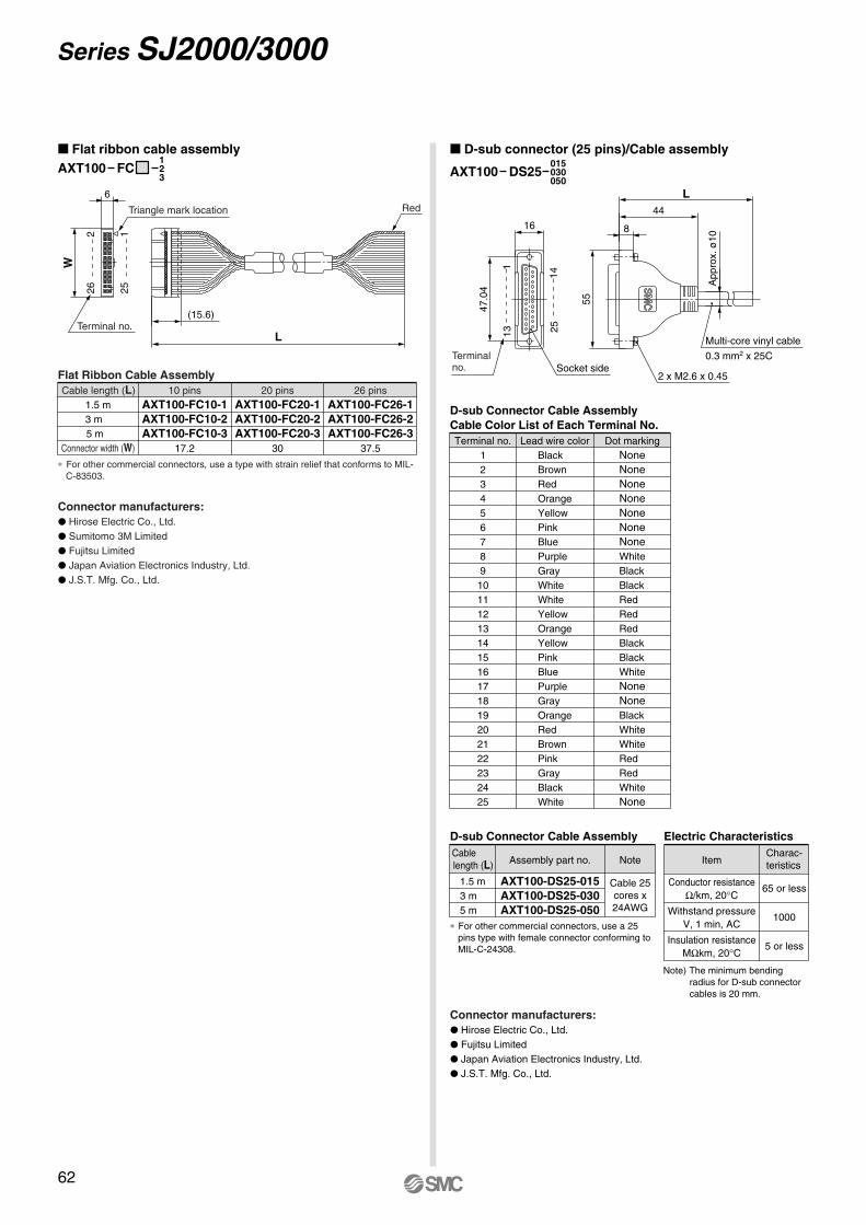
M Flat ribbon cable assemblyAXT100 FC
123
∗ For other commercial connectors, use a type with strain relief that conforms to MIL-C-83503.
L
(15.6)
6
W
Red
Terminal no.
226 25
1
Triangle mark location
Cable length (L) 10 pins1.5 m 3 m5 m
AXT100-FC10-1 AXT100-FC10-2 AXT100-FC10-3
17.2
20 pinsAXT100-FC20-1 AXT100-FC20-2 AXT100-FC20-3
30
26 pinsAXT100-FC26-1 AXT100-FC26-2 AXT100-FC26-3
37.5
Flat Ribbon Cable Assembly
Connector manufacturers: P Hirose Electric Co., Ltd. P Sumitomo 3M Limited P Fujitsu Limited P Japan Aviation Electronics Industry, Ltd. P J.S.T. Mfg. Co., Ltd.
M D-sub connector (25 pins)/Cable assembly
AXT100 DS25015 030 050
∗ For other commercial connectors, use a 25 pins type with female connector conforming to MIL-C-24308.
Note)The minimum bending radius for D-sub connector cables is 20 mm.
Connector manufacturers: P Hirose Electric Co., Ltd. P Fujitsu Limited P Japan Aviation Electronics Industry, Ltd. P J.S.T. Mfg. Co., Ltd.
App
rox.
ø10
55
47.0
4
8
L44
16
Terminal no.
2 x M2.6 x 0.45
0.3 mm2 x 25C
131
2514
Multi-core vinyl cable
Socket side
Terminal no. Lead wire color123456789
10 11 12 13 14 15 16 17 18 19 20 21 22 23 24 25
Black Brown Red Orange Yellow Pink Blue Purple Gray White White Yellow Orange Yellow Pink Blue Purple Gray Orange Red Brown Pink Gray Black White
Dot marking None None None None None None None White Black Black Red Red Red Black Black White None None Black White White Red Red White None
D-sub Connector Cable Assembly Cable Color List of Each Terminal No.
1.5 m 3 m5 m
AXT100-DS25-015 AXT100-DS25-030 AXT100-DS25-050
Cable length (L)
D-sub Connector Cable Assembly
Assembly part no. Note
Cable 25 cores x 24AWG
Conductor resistance Ω/km, 20°C
65 or less
Withstand pressure V, 1 min, AC
1000
Insulation resistance MΩkm, 20°C
5 or less
Item Charac- teristics
Electric Characteristics
Connector width (W)
62
Series SJ2000/3000
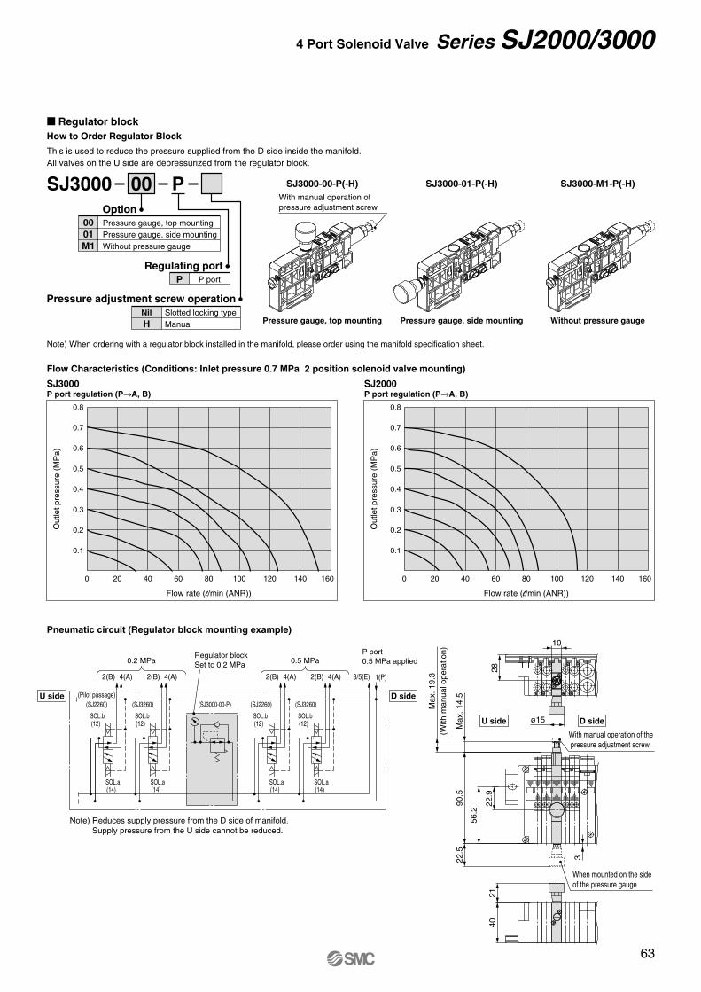
M Regulator block How to Order Regulator Block This is used to reduce the pressure supplied from the D side inside the manifold. All valves on the U side are depressurized from the regulator block.
SJ3000 P
P portPRegulating port
Pressure gauge, top mounting Pressure gauge, side mounting Without pressure gauge
00 01 M1
Option
Slotted locking type Manual
Nil H
Pressure adjustment screw operation
00
Pneumatic circuit (Regulator block mounting example)
SJ3000-01-P(-H) SJ3000-M1-P(-H)SJ3000-00-P(-H)
Pressure gauge, side mounting Without pressure gaugePressure gauge, top mounting
Flow Characteristics (Conditions: Inlet pressure 0.7 MPa 2 position solenoid valve mounting)
SJ3000 P port regulation (P→A, B)
SJ2000 P port regulation (P→A, B)
Note) Reduces supply pressure from the D side of manifold. Supply pressure from the U side cannot be reduced.
Note) When ordering with a regulator block installed in the manifold, please order using the manifold specification sheet.
D side(SJ3000-00-P)
P port 0.5 MPa applied0.5 MPa
Regulator block Set to 0.2 MPa0.2 MPa
U side(SJ3260)
SOL.b
(14)SOL.a
(12)
4(A)2(B)
(SJ2260)
SOL.b
(14)SOL.a
(12)
4(A)2(B)
SOL.b
(14)SOL.a
(12)
(SJ3260)(SJ2260)
SOL.b
(14)SOL.a
(12)
3/5(E)
(Pilot passage)
4(A)2(B) 4(A)2(B) 1(P)
0.8
0.7
0.6
0.5
0.4
0.3
0.2
0.1
Out
letp
ress
ure
(MP
a)
Flow rate (l/min (ANR))
0 20 40 60 80 100 120 140 160
0.8
0.7
0.6
0.5
0.4
0.3
0.2
0.1
Out
letp
ress
ure
(MP
a)
Flow rate (l/min (ANR))
0 20 40 60 80 100 120 140 160
53/
1
2
4
D
2
4
DD
2
4
D
2
4
10
ø15
2821
40
Max
.19.
3(W
ithm
anua
lope
ratio
n)
22.5
90.5
3
22.9
Max
.14.
5
56.2
With manual operation of the pressure adjustment screw
When mounted on the side of the pressure gauge
With manual operation of pressure adjustment screw
D sideU side
63
4 Port Solenoid Valve Series SJ2000/3000
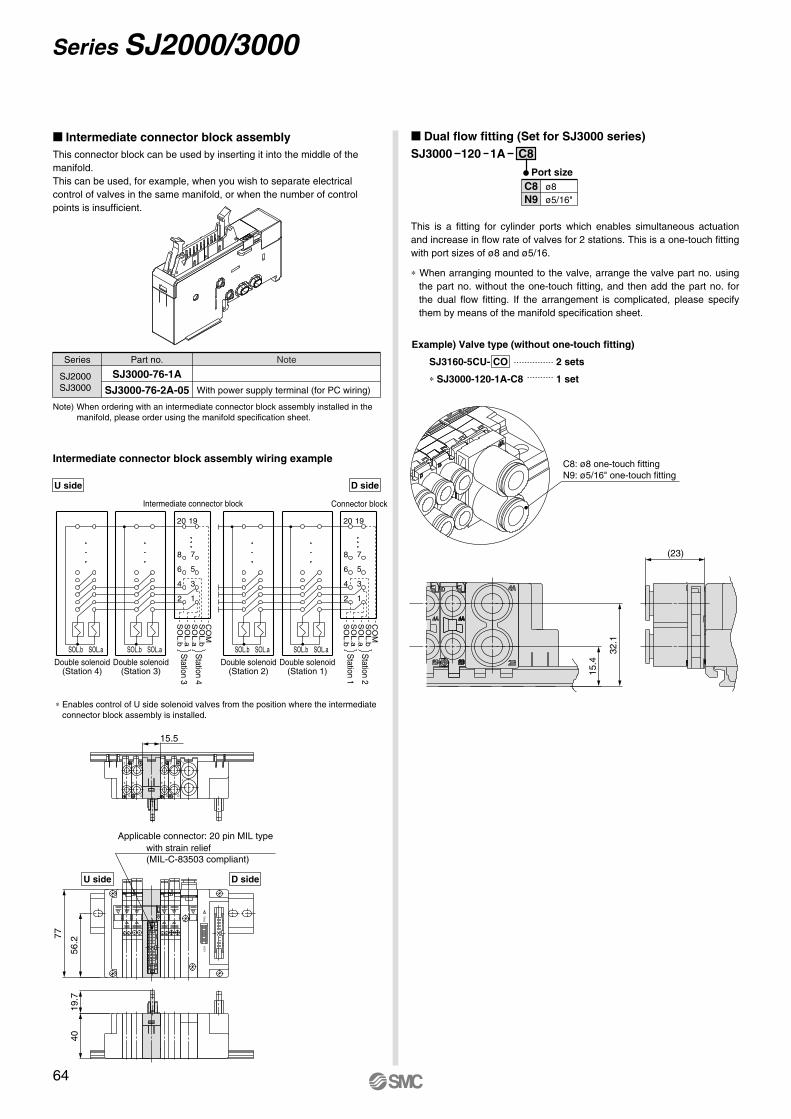
M Intermediate connector block assembly This connector block can be used by inserting it into the middle of the manifold.This can be used, for example, when you wish to separate electrical control of valves in the same manifold, or when the number of control points is insufficient.
This is a fitting for cylinder ports which enables simultaneous actuation and increase in flow rate of valves for 2 stations. This is a one-touch fitting with port sizes of ø8 and ø5/16.
∗ When arranging mounted to the valve, arrange the valve part no. using the part no. without the one-touch fitting, and then add the part no. for the dual flow fitting. If the arrangement is complicated, please specify them by means of the manifold specification sheet.
Note) When ordering with an intermediate connector block assembly installed in the manifold, please order using the manifold specification sheet.
SJ3000-76-1A
SJ3000-76-2A-05
Series Part no. Note
SJ2000 SJ3000 With power supply terminal (for PC wiring)
53/
1
2
4
D
2
4
DD
2
4
D
2
4
15.5
FRE
ELO
CK
Applicable connector: 20 pin MIL type with strain relief (MIL-C-83503 compliant)
77
56.2
19.7
40
Intermediate connector block assembly wiring example
CO
M
SOL.aSOL.b SOL.b SOL.a
(Station 2)Double solenoid
20 19
8
6
4
7
5
3
2 1
Station
1
Station
2
(Station 1)Double solenoid
SO
L.b
SO
L.a
SO
L.a
SO
L.b
CO
M
SOL.aSOL.b SOL.b SOL.a
(Station 4)Double solenoid
20 19
8
6
4
7
5
3
2 1S
tation3
Station
4
(Station 3)Double solenoid
SO
L.b
SO
L.a
SO
L.a
SO
L.b
Connector blockIntermediate connector block
∗ Enables control of U side solenoid valves from the position where the intermediate connector block assembly is installed.
M Dual flow fitting (Set for SJ3000 series)SJ3000 120 1A C8
Port size
C8: ø8 one-touch fitting N9: ø5/16" one-touch fitting
(23)
32.1
15.4
ø8 ø5/16"
C8 N9
Example) Valve type (without one-touch fitting)
SJ3160-5CU- CO 2 sets
∗ SJ3000-120-1A-C8 1 set
D sideU side
D sideU side
64
Series SJ2000/3000
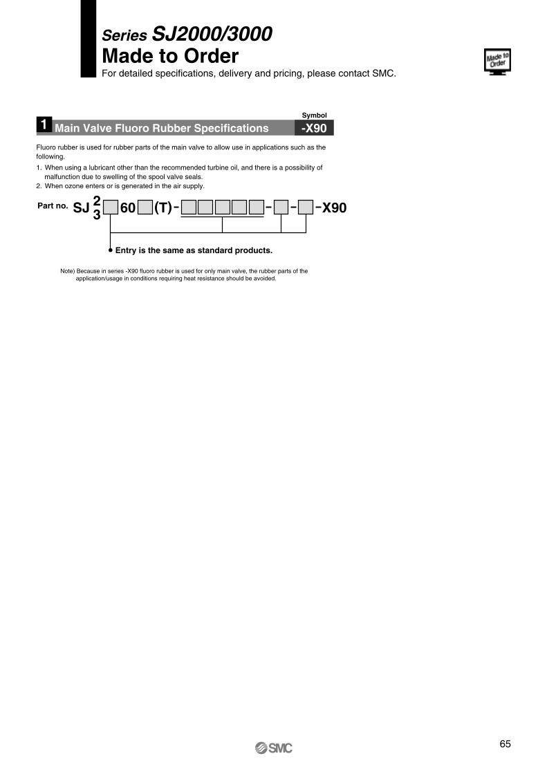
Part no.
1 Main Valve Fluoro Rubber Specifications -X90Symbol
Series SJ2000/3000 Made to Order For detailed specifications, delivery and pricing, please contact SMC.
Entry is the same as standard products.
SJ 60 X90(T)23
Fluoro rubber is used for rubber parts of the main valve to allow use in applications such as the following.
1.When using a lubricant other than the recommended turbine oil, and there is a possibility of malfunction due to swelling of the spool valve seals.
2.When ozone enters or is generated in the air supply.
Note) Because in series -X90 fluoro rubber is used for only main valve, the rubber parts of the application/usage in conditions requiring heat resistance should be avoided.
65
Recommended