The XBEE Enzyme Fuel Technology has been awarded the Lean & Green Tools Certificate.
Enzyme Fuel Technology
OFFIZIELLER CEC-PRÜFUNGENDiesel & Benzin
EINHALTUNG DER MOTORENDer europäische Koordinierungsausschuss (CEC) für die Entwicklung von Prüfverfahren für Kraft- und Schmierstoffe sowie sonstige flüssige Betriebsmedien ist eine europäische Einrichtung mit der über 50 Hersteller aus der Automobil-, Erdöl- und Schmiermittelbranche zusammenarbeiten.
© 2020 XBEE SA - XBEE® Enzyme Fuel Technology ist eine eingetragene Marke.www.xbeefuel.de
1 · DieselmotorenBei Dieselmotoren wird im Rahmen des Verfahrens CEC F-23-A-01 die Russablagerung in einem Referenzmotor mit indirekter Einspritzung (PSA Peugeot XUD9 – A/L 4 Zylinder – 1.9 Liter) bewertet.
Die beiden aufeinander folgenden Tests wurden von dem englischen Prüflabor Prodrive am 17. und 18. Juli 2005 unter dem wachsamen Auge von Garry Polkinghorne durchgeführt.
Um von den nachfolgenden Firmen anerkannt zu werden, müssen die Werte beim Test (Einspritzdüsensauberkeit) zwischen 85% und 95% liegen. Das Ergebnis: beim Einsatz des Enzyms XBEE erreicht der Kraftstoff innerhalb von nur 10 Stunden 91% bzw. 92%.
2 · BenzinmotorenBei Benzinmotoren wird im Rahmen des Verfahrens CEC F-05-A-93 die Russablagerung an den Einlassventilen bei einem Referenz-Einspritzmotor (Mercedes-Benz M102.982 – 4 Zylinder – 4 Takter – 2.3 Liter) bewertet, der mit Bosch KE-Jetronic Einspritzung ausgestattet ist.
Dieser Test wurde von dem englischen Prüflabor Prodrive am 22. Juli 2005 unter dem wachsamen Auge von Garry Polkinghorne durchgeführt.
Um von den nachfolgenden Firmen anerkannt zu werden, muss der Verschmutzungsgrad zwischen 4.5 (stark verschmutzt) und 10 (sauber) liegen: durch den Einsatz des Enzyms XBEE erreicht der Kraftstoff innerhalb von nur 60 Stunden 8.07, d.h. 287 mg im Schnitt (und als Spitzenwert 215 mg) im Vergleich zu 314.25 mg beim gleichen, nicht mit XBEE behandelten Kraftstoff im gleichen Motor.
Enzyme Fuel Technology
OFFIZIELLER CEC-PRÜFUNGENDiesel & Benzin
ACEA-MITGLIEDER, DIE DIE CEC-TESTS ANERKENNEN
© 2020 XBEE SA - XBEE® Enzyme Fuel Technology ist eine eingetragene Marke.www.xbeefuel.de

Enzyme Fuel Technology
OFFIZIELLER CEC-PRÜFUNGENDiesel & Benzin
ACEA-MITGLIEDER, DIE DIE CEC-TESTS ANERKENNEN
© 2020 XBEE SA - XBEE® Enzyme Fuel Technology ist eine eingetragene Marke.www.xbeefuel.de

XUD-9 Nozzle Coking Test
Test procedure : CEC F-23-A-01 Issue 13
Test Number : XBXUD001
Client : Xbee
Fuel Code : RF93T095
Additive Code : Xbee
Treat Rate : 4000:1 by volume
Test Complete Date : 17-Jul-05
Client Address : Avenue de Bielefeld Senne
29900 Concarneau
France
Client Distribution : Ronan Pennec
Client Order Number : 300030168000020638668
Test Items Supplied By : Xbee
Test Fuel Received Date : 22-Jun-04
Test Additive Received Date : 11-Jul-05
Test Lubricant : RL223
Authorised by: G. Polkinghorne

CEC F-23-A-01 Diesel Nozzle Coking Test 1
Contents
1. Introduct ion . .. 2
2. Test descript ion .. ..2
2.1 Test engine ... . ..2
2.2 Engine build and item preparat ion . .2
2.3 Test procedure .. .. ..2
2.4 Engine warm-up .. ..3
2.5 Other operat ing parameters .. ... . ..3
3. Results . .4
3.1 Pre test nozzle f lows ... . .4
3.2 Post test nozzle f lows .. ..5
3.3 Flow loss calculat ions .. . .6
4. Unscheduled occurences ... 7
5. Reference history ..8

CEC F-23-A-01 Diesel Nozzle Coking Test 2
1.0 Introduction
2.0 Test description
2.1 Test engine
Engine part number: 70100
Swept volume: 1.9 litre
Injection Pump: Roto Diesel DCP R 84 43 B910A
Injector body: Lucas LCR 67307
Injector nozzle: Lucas RDNO SDC 6850 (unflatted)
Firing order: 1,3,4,2 (No. 1 at flywheel end)
2.2 Engine build and item preparation
2.3 Test procedure
This test method is designed to evaluate the capability of a diesel fuel to control the formation of deposits on the injector nozzles of an Indirect Injection diesel engine. Results of tests run to this method are expressed in terms of the percentage airflow loss at various injector needle lift points. Airflow measurements are accomplished with an airflow rig complying with ISO 4010.
The engine used for this test is a Peugeot XUD9AL unit supplied by PSA specifically for Nozzle Coking Testing, originally at the request of the CEC PF-023 Working Group.
The injector nozzles are cleaned and checked for airflow at 0.05, 0.1, 0.2, 0.3 and 0.4mm lift. Nozzles are discarded if the airflow is outside of the range 250ml/min to 320ml/min. The nozzles are assembled into the injector bodies and the opening pressures set to 115±5 bar.
A slave set of injectors is fitted to the engine. The previous test fuel is drained from the system. The engine is run for 25 minutes in order to flush through the fuel system. During this time all the spill-off fuel is discarded and not returned. The engine is then set to test speed and load and all specified parameters checked and adjusted to the test specification. The slave injectors are then replaced with the test units.

CEC F-23-A-01 Diesel Nozzle Coking Test 3
2.4 Engine warm-up
Engine Warm-upDuration Speed/load
(mins)5 Idle speed / no load
10 2000 rev/min / 34Nm torque
10 3000 rev/min / 50 Nm torque
Test Operating ConditionsStage Time
(secs)1 30 1200 ± 30 10 ± 2
2 60 3000 ± 30 50 ± 2
3 60 1300 ± 30 35 ± 2
4 120 1850 ± 30 50 ± 2
2.5 Other operating parameters
Run ParametersCoolant outlet temperature (°C)
Coolant delta (°C)
Oil gallery temperature (°C)
Air inlet temperature (°C)
Fuel temperature at pump (°C)
Fuel pump inlet pressure - stage 2 (mbar)
Fuel pump outlet pressure - stage 2 (mbar)
Exhaust back pressure - stage 2 (mbar)
Air Intake Pressure (mbar)
Speed(rev/min)
Torque(Nm)
950 ± 10
-100 to +100
50 ± 10
95 ± 2
4 ± 2
100 ± 5
32 ± 2
31 ± 2
-50 to +100
Immediately after the warm-up the following test cycle is run 134 times giving a total test time of 10 hours and 3 minutes.

CEC F-23-A-01 Diesel Nozzle Coking Test 4
Test Number : XBXUD001
Fuel Code : RF93T095
Additive Code : Xbee
Treat rate : 4000:1 by volume
3.0 Results
3.1 Pre-test
Reference (Nozzle 215) SettingsLift Reading Obs. Flow Corr. Flow Test Hours 0
(mm) % (cc/min) (cc/min) Date
0 0.1 1 1 Operator AH
0.1 47.6 238 258 Ambient press (mbar) 1009.9 ( = Pa)Ambient temp. (°K) 298.0 ( = Ta)
Meter SpecificationSerial No. Max Flow (cc/min) Pi Ti
98205460A 500 273
Cylinder 1 Nozzle: F17 Cylinder 2 Nozzle: F18Lift Reading Obs.Flow Corr.Flow Lift Reading Obs.Flow Corr.Flow
(mm) (%) (cc/min) (cc/min) (mm) (%) (cc/min) (cc/min)
0 0.1 1 1 0 0.1 1 1
0.05 43.2 216 235 0.05 40.7 204 221
0.1 51.2 256 278 0.1 50.5 253 274
0.2 63.4 317 344 0.2 65.9 330 358
0.3 78.8 394 428 0.3 81.5 408 443
0.4 98.2 491 533 0.4 96.1 481 522
Cylinder 3 Nozzle: F19 Cylinder 4 Nozzle: F20Lift Reading Obs. Flow Corr. Flow Lift Reading Obs. Flow Corr. Flow
(mm) (%) (cc/min) (cc/min) (mm) (%) (cc/min) (cc/min)
0 0.1 1 1 0 0.1 1 1
0.05 41.0 205 223 0.05 40.6 203 220
0.1 52.2 261 283 0.1 51.7 259 281
0.2 67.8 339 368 0.2 66.6 333 362
0.3 83.6 418 454 0.3 82.2 411 446
0.4 99.9 500 542 0.4 97.7 489 530
1013.25
16-Jul-05
°K in flowmeter mass of etemperatur nCalibratio =
°K in etemperatur Ambient =
mbar in pressure Ambient =
mbar in flowmeter mass of pressure nCalibratio = where
293*flow Observed flow Corrected
i
a
a
i
ai
a
a
i
T
T
P
P
T*
T
T*
P
P

CEC F-23-A-01 Diesel Nozzle Coking Test 5
Test Number : XBXUD001
Fuel Code : RF93T095
Additive Code : Xbee
Treat rate : 4000:1 by volume
3.2 Post-test
Reference (Nozzle 215) SettingsLift Reading Obs. Flow Corr. Flow Test Hours: 10
(mm) % (cc/min) (cc/min) Date:
0 0.1 1 1 Operator: AH
0.1 47.8 239 258 Ambient press (mbar) 1009.8 ( = Pa)Ambient temp. (°K) 295.2 ( = Ta)
Meter SpecificationSerial No. Max Flow (cc/min) Pi Ti
98205460A 500 273
Cylinder 1 Nozzle: F17 Cylinder 2 Nozzle: F18Lift Reading Obs.Flow Corr.Flow Lift Reading Obs.Flow Corr.Flow
(mm) (%) (cc/min) (cc/min) (mm) (%) (cc/min) (cc/min)
0 0.1 1 1 0 0.1 1 1
0.05 3.8 19 21 0.05 2.1 11 11
0.1 4.9 25 26 0.1 2.7 14 15
0.2 9.4 47 51 0.2 5.0 25 27
0.3 17.7 89 96 0.3 12.5 63 68
0.4 41.9 210 226 0.4 35.4 177 191
Cylinder 3 Nozzle: F19 Cylinder 4 Nozzle: F20Lift Reading Obs.Flow Corr.Flow Lift Reading Obs.Flow Corr.Flow
(mm) (%) (cc/min) (cc/min) (mm) (%) (cc/min) (cc/min)
0 0.1 1 1 0 0.1 1 1
0.05 5.1 26 28 0.05 3.4 17 18
0.1 6.9 35 37 0.1 4.4 22 24
0.2 13.3 67 72 0.2 7.0 35 38
0.3 27.0 135 146 0.3 12.4 62 67
0.4 50.3 252 272 0.4 30.3 152 164
1013.25
17-Jul-05
°K in flowmeter mass of etemperatur nCalibratio =
°K in etemperatur Ambient =
mbar in pressure Ambient =
mbar in flowmeter mass of pressure nCalibratio = where
293*flow Observed flow Corrected
i
a
a
i
ai
a
a
i
T
T
P
P
T*
T
T*
P
P
CEC F-23-A-01 Diesel Nozzle Coking Test 6
Test Number : XBXUD001
Fuel Code : RF93T095
Additive Code : Xbee
Treat rate : 4000:1 by volume
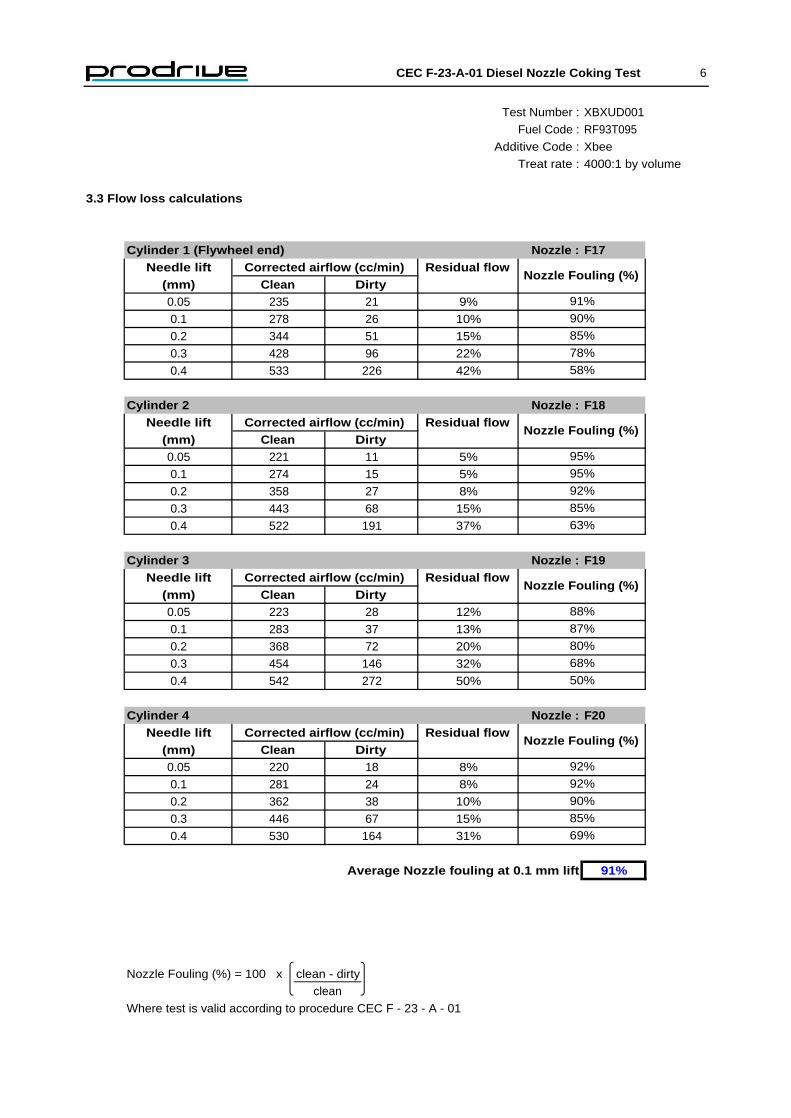
3.3 Flow loss calculations
Cylinder 1 (Flywheel end) Nozzle : F17Needle lift Corrected airflow (cc/min) Residual flow
(mm) Clean Dirty0.05 235 21 9%
0.1 278 26 10%
0.2 344 51 15%
0.3 428 96 22%
0.4 533 226 42%
Cylinder 2 Nozzle : F18Needle lift Corrected airflow (cc/min) Residual flow
(mm) Clean Dirty0.05 221 11 5%
0.1 274 15 5%
0.2 358 27 8%
0.3 443 68 15%
0.4 522 191 37%
Cylinder 3 Nozzle : F19Needle lift Corrected airflow (cc/min) Residual flow
(mm) Clean Dirty0.05 223 28 12%
0.1 283 37 13%
0.2 368 72 20%
0.3 454 146 32%
0.4 542 272 50%
Cylinder 4 Nozzle : F20Needle lift Corrected airflow (cc/min) Residual flow
(mm) Clean Dirty0.05 220 18 8%
0.1 281 24 8%
0.2 362 38 10%
0.3 446 67 15%
0.4 530 164 31%
Average Nozzle fouling at 0.1 mm lift 91%
Nozzle Fouling (%) = 100 x clean - dirty
clean
Where test is valid according to procedure CEC F - 23 - A - 01
Nozzle Fouling (%)
91%
85%
69%
92%
92%
68%
Nozzle Fouling (%)
Nozzle Fouling (%)
50%
87%
88%
Nozzle Fouling (%)
85%
95%
92%
90%
80%
90%
85%
78%
58%
63%
95%

CEC F-23-A-01 Diesel Nozzle Coking Test 7
4.0 Unscheduled occurences
Unschedulded IssuesTest Duration Time off Issue
(hours) Test
Unschedulded ShutdownsTest Duration Time off Reason for shutdown
(hours) Test
DeviationsTest Duration Max Name of "out of spec" parameter
(hours) deviation

CEC F-23-A-01 Diesel Nozzle Coking Test 8
5.0 Referencing history
Average % fouling @ 0.1mm liftTests Test No. Date RF93T095 Fuel DF90 Fuel
35 PD-XUD9-154 18-Dec-04 91%
51 PD-XUD9-163 09-Jan-05 68%
DF90 Batch 3 calibration fuel produces a 75% ± 3% average nozzle fouling
61 PD-XUD9-176 13-Apr-05 75%
62 PD-XUD9-177 22-Apr-05 78%
63 PD-XUD9-178 23-Apr-05 74%
66 PD-XUD9-180 26-Apr-05 92%
90 PD-XUD9-186 20-Jun-05 76%
111 PD-XUD9-187 08-Jul-05 77%
Two calibration fuels have been selected to enable the tuning of the XUD9A/L engine.
CEC reference fuel RF93-T-95 is used as the severe calibration product and the result from this test should provide a result of 90±5% average nozzle blockage at 0.1mm needle lift.
CEC Calibration fuel DF90 is used as an additised calibration product and currently the result from this test should provide a result of 75±3% as a rolling average of the last three tests.

XUD-9 Nozzle Coking Test
Test procedure : CEC F-23-A-01 Issue 13
Test Number : XBXUD002
Client : Xbee
Fuel Code : RF93T095
Additive Code : Xbee
Treat Rate : 4000:1 by volume
Test Complete Date : 18-Jul-05
Client Address : Avenue de Bielefeld Senne
29900 Concarneau
France
Client Distribution : Ronan Pennec
Client Order Number : 300030168000020638668
Test Items Supplied By : Xbee
Test Fuel Received Date : 22-Jun-04
Test Additive Received Date : 11-Jul-05
Test Lubricant : RL223
Authorised by: G. Polkinghorne

CEC F-23-A-01 Diesel Nozzle Coking Test 1
Contents
1. Introduct ion . .. 2
2. Test descript ion .. ..2
2.1 Test engine ... . ..2
2.2 Engine build and item preparat ion . .2
2.3 Test procedure .. .. ..2
2.4 Engine warm-up .. ..3
2.5 Other operat ing parameters .. ... . ..3
3. Results . .4
3.1 Pre test nozzle f lows ... . .4
3.2 Post test nozzle f lows .. ..5
3.3 Flow loss calculat ions .. . .6
4. Unscheduled occurences ... 7
5. Reference history ..8

CEC F-23-A-01 Diesel Nozzle Coking Test 2
1.0 Introduction
2.0 Test description
2.1 Test engine
Engine part number: 70100
Swept volume: 1.9 litre
Injection Pump: Roto Diesel DCP R 84 43 B910A
Injector body: Lucas LCR 67307
Injector nozzle: Lucas RDNO SDC 6850 (unflatted)
Firing order: 1,3,4,2 (No. 1 at flywheel end)
2.2 Engine build and item preparation
2.3 Test procedure
This test method is designed to evaluate the capability of a diesel fuel to control the formation of deposits on the injector nozzles of an Indirect Injection diesel engine. Results of tests run to this method are expressed in terms of the percentage airflow loss at various injector needle lift points. Airflow measurements are accomplished with an airflow rig complying with ISO 4010.
The engine used for this test is a Peugeot XUD9AL unit supplied by PSA specifically for Nozzle Coking Testing, originally at the request of the CEC PF-023 Working Group.
The injector nozzles are cleaned and checked for airflow at 0.05, 0.1, 0.2, 0.3 and 0.4mm lift. Nozzles are discarded if the airflow is outside of the range 250ml/min to 320ml/min. The nozzles are assembled into the injector bodies and the opening pressures set to 115±5 bar.
A slave set of injectors is fitted to the engine. The previous test fuel is drained from the system. The engine is run for 25 minutes in order to flush through the fuel system. During this time all the spill-off fuel is discarded and not returned. The engine is then set to test speed and load and all specified parameters checked and adjusted to the test specification. The slave injectors are then replaced with the test units.

CEC F-23-A-01 Diesel Nozzle Coking Test 3
2.4 Engine warm-up
Engine Warm-upDuration Speed/load
(mins)5 Idle speed / no load
10 2000 rev/min / 34Nm torque
10 3000 rev/min / 50 Nm torque
Test Operating ConditionsStage Time
(secs)1 30 1200 ± 30 10 ± 2
2 60 3000 ± 30 50 ± 2
3 60 1300 ± 30 35 ± 2
4 120 1850 ± 30 50 ± 2
2.5 Other operating parameters
Run ParametersCoolant outlet temperature (°C)
Coolant delta (°C)
Oil gallery temperature (°C)
Air inlet temperature (°C)
Fuel temperature at pump (°C)
Fuel pump inlet pressure - stage 2 (mbar)
Fuel pump outlet pressure - stage 2 (mbar)
Exhaust back pressure - stage 2 (mbar)
Air Intake Pressure (mbar)
Speed(rev/min)
Torque(Nm)
950 ± 10
-100 to +100
50 ± 10
95 ± 2
4 ± 2
100 ± 5
32 ± 2
31 ± 2
-50 to +100
Immediately after the warm-up the following test cycle is run 134 times giving a total test time of 10 hours and 3 minutes.

CEC F-23-A-01 Diesel Nozzle Coking Test 4
Test Number : XBXUD002
Fuel Code : RF93T095
Additive Code : Xbee
Treat rate : 4000:1 by volume
3.0 Results
3.1 Pre-test
Reference (Nozzle 215) SettingsLift Reading Obs. Flow Corr. Flow Test Hours 0
(mm) % (cc/min) (cc/min) Date
0 0.1 1 1 Operator AH
0.1 47.3 237 258 Ambient press (mbar) 1007.9 ( = Pa)Ambient temp. (°K) 298.6 ( = Ta)
Meter SpecificationSerial No. Max Flow (cc/min) Pi Ti
98205460A 500 273
Cylinder 1 Nozzle: F17 Cylinder 2 Nozzle: F18Lift Reading Obs.Flow Corr.Flow Lift Reading Obs.Flow Corr.Flow
(mm) (%) (cc/min) (cc/min) (mm) (%) (cc/min) (cc/min)
0 0.1 1 1 0 0.1 1 1
0.05 44.6 223 243 0.05 40.9 205 223
0.1 51.8 259 282 0.1 51.1 256 278
0.2 64.8 324 353 0.2 66.0 330 359
0.3 80.8 404 440 0.3 81.6 408 444
0.4 100.8 504 549 0.4 96.3 482 524
Cylinder 3 Nozzle: F19 Cylinder 4 Nozzle: F20Lift Reading Obs. Flow Corr. Flow Lift Reading Obs. Flow Corr. Flow
(mm) (%) (cc/min) (cc/min) (mm) (%) (cc/min) (cc/min)
0 0.1 1 1 0 0.1 1 1
0.05 40.4 202 220 0.05 39.9 200 217
0.1 52.2 261 284 0.1 51.7 259 282
0.2 68.0 340 370 0.2 66.9 335 364
0.3 84.1 421 458 0.3 82.8 414 451
0.4 100.9 505 549 0.4 98.5 493 536
1013.25
17-Jul-05
°K in flowmeter mass of etemperatur nCalibratio =
°K in etemperatur Ambient =
mbar in pressure Ambient =
mbar in flowmeter mass of pressure nCalibratio = where
293*flow Observed flow Corrected
i
a
a
i
ai
a
a
i
T
T
P
P
T*
T
T*
P
P

CEC F-23-A-01 Diesel Nozzle Coking Test 5
Test Number : XBXUD002
Fuel Code : RF93T095
Additive Code : Xbee
Treat rate : 4000:1 by volume
3.2 Post-test
Reference (Nozzle 215) SettingsLift Reading Obs. Flow Corr. Flow Test Hours: 10
(mm) % (cc/min) (cc/min) Date:
0 0.1 1 1 Operator: GP
0.1 46.9 235 257 Ambient press (mbar) 1000.44 ( = Pa)Ambient temp. (°K) 298.0 ( = Ta)
Meter SpecificationSerial No. Max Flow (cc/min) Pi Ti
98205460A 500 273
Cylinder 1 Nozzle: F17 Cylinder 2 Nozzle: F18Lift Reading Obs.Flow Corr.Flow Lift Reading Obs.Flow Corr.Flow
(mm) (%) (cc/min) (cc/min) (mm) (%) (cc/min) (cc/min)
0 0.1 1 1 0 0.1 1 1
0.05 2.8 14 15 0.05 2.8 14 15
0.1 3.6 18 20 0.1 3.5 18 19
0.2 6.8 34 37 0.2 5.8 29 32
0.3 15.2 76 83 0.3 11.8 59 65
0.4 41.5 208 227 0.4 32.6 163 179
Cylinder 3 Nozzle: F19 Cylinder 4 Nozzle: F20Lift Reading Obs.Flow Corr.Flow Lift Reading Obs.Flow Corr.Flow
(mm) (%) (cc/min) (cc/min) (mm) (%) (cc/min) (cc/min)
0 0.1 1 1 0 0.1 1 1
0.05 3.2 16 18 0.05 4.2 21 23
0.1 4.1 21 22 0.1 5.4 27 30
0.2 7.4 37 41 0.2 8.6 43 47
0.3 17.9 90 98 0.3 16.4 82 90
0.4 47.9 240 263 0.4 44.4 222 243
1013.25
18-Jul-05
°K in flowmeter mass of etemperatur nCalibratio =
°K in etemperatur Ambient =
mbar in pressure Ambient =
mbar in flowmeter mass of pressure nCalibratio = where
293*flow Observed flow Corrected
i
a
a
i
ai
a
a
i
T
T
P
P
T*
T
T*
P
P

CEC F-23-A-01 Diesel Nozzle Coking Test 6
Test Number : XBXUD002
Fuel Code : RF93T095
Additive Code : Xbee
Treat rate : 4000:1 by volume
3.3 Flow loss calculations
Cylinder 1 (Flywheel end) Nozzle : F17Needle lift Corrected airflow (cc/min) Residual flow
(mm) Clean Dirty0.05 243 15 6%
0.1 282 20 7%
0.2 353 37 11%
0.3 440 83 19%
0.4 549 227 41%
Cylinder 2 Nozzle : F18Needle lift Corrected airflow (cc/min) Residual flow
(mm) Clean Dirty0.05 223 15 7%
0.1 278 19 7%
0.2 359 32 9%
0.3 444 65 15%
0.4 524 179 34%
Cylinder 3 Nozzle : F19Needle lift Corrected airflow (cc/min) Residual flow
(mm) Clean Dirty0.05 220 18 8%
0.1 284 22 8%
0.2 370 41 11%
0.3 458 98 21%
0.4 549 263 48%
Cylinder 4 Nozzle : F20Needle lift Corrected airflow (cc/min) Residual flow
(mm) Clean Dirty0.05 217 23 11%
0.1 282 30 11%
0.2 364 47 13%
0.3 451 90 20%
0.4 536 243 45%
Average Nozzle fouling at 0.1 mm lift 92%
Nozzle Fouling (%) = 100 x clean - dirty
clean
Where test is valid according to procedure CEC F - 23 - A - 01
Nozzle Fouling (%)
94%
80%
55%
89%
89%
79%
Nozzle Fouling (%)
Nozzle Fouling (%)
52%
92%
92%
Nozzle Fouling (%)
85%
93%
91%
87%
89%
93%
89%
81%
59%
66%
93%

CEC F-23-A-01 Diesel Nozzle Coking Test 7
4.0 Unscheduled occurences
Unschedulded IssuesTest Duration Time off Issue
(hours) Test
Unschedulded ShutdownsTest Duration Time off Reason for shutdown
(hours) Test
DeviationsTest Duration Max Name of "out of spec" parameter
(hours) deviation

CEC F-23-A-01 Diesel Nozzle Coking Test 8
5.0 Referencing history
Average % fouling @ 0.1mm liftTests Test No. Date RF93T095 Fuel DF90 Fuel
35 PD-XUD9-154 18-Dec-04 91%
51 PD-XUD9-163 09-Jan-05 68%
DF90 Batch 3 calibration fuel produces a 75% ± 3% average nozzle fouling
61 PD-XUD9-176 13-Apr-05 75%
62 PD-XUD9-177 22-Apr-05 78%
63 PD-XUD9-178 23-Apr-05 74%
66 PD-XUD9-180 26-Apr-05 92%
90 PD-XUD9-186 20-Jun-05 76%
111 PD-XUD9-187 08-Jul-05 77%
Two calibration fuels have been selected to enable the tuning of the XUD9A/L engine.
CEC reference fuel RF93-T-95 is used as the severe calibration product and the result from this test should provide a result of 90±5% average nozzle blockage at 0.1mm needle lift.
CEC Calibration fuel DF90 is used as an additised calibration product and currently the result from this test should provide a result of 75±3% as a rolling average of the last three tests.

M-102-E Intake Valve Deposit Test
Test procedure : CEC F-05-A-93
Test Number : XB102001
Client : Xbee
Client Address : Avenue de Bielefeld Senne
29900 Concarneau
France
Client Distribution : Ronan Pennec
Client Order Number : 30003016800020600000
Fuel Code : DF12 batch 5
Test Fuel Received Date : 14-Jul-05
Additive Code : Xbee
Treat Rate : 4000:1
Test Additive Received Date : 11-Jul-05
Test Oil : RL223
Test Complete Date : 22-Jul-05
Project Engineer : G.Polkinghorne

CEC F-05-A-93 Inlet Valve Cleanliness Test 1
Contents
1. Introduct ion . .. 2
2. Test descript ion .. ..2
2.1 Test engine ... . ..2
2.2 Engine preparat ion . . .2
2.3 Test procedure .. .. ..2
2.4 Operat ing parameters .. ..3
2.5 End of test assessment 3
2.6 Pre-test checks .4
3. Results . .4
3.1 Results summary . .5
3.2 Emissions summary .6
3.3 Averaged operat ional data 7
3.4 Inlet valve merit rat ings ..8,9
3.5 Inlet valve photography .10
4. Unscheduled occurences ... 11

CEC F-05-A-93 Inlet Valve Cleanliness Test 2
Test description
The engine
Bore/Stroke - 95.50 / 80.25 mm
Swept Volume - 2299 cc
Compression Ratio - 9.0 : 1
Maximum Power - 100kW @ 5100 rev/min
Engine preparation
Test procedure
The engine is mounted on a test stand and operated for 800 cycles, totalling 60 hours. The cycle consists of four stages and is designed to represent urban driving conditions. Ignition advance and exhaust CO content are set prior to the start of the test.
The test engine is fitted with a cleaned cylinder head, which in turn has been fitted with new inlet valves. The inlet valves are pegged to prevent rotation. Fresh oil and a new oil filter are used for each test.
The procedure utilises a Mercedes-Benz M102.982 four cylinder, four stroke 2.3 litre gasoline engine. The engine is equipped with Bosch KE-Jetronic fuel injection equipment and has the following specification :-
This test method is designed to evaluate the propensity of gasoline or gasoline additive formulations to prevent inlet valve deposits in fuel injected engines. Results of tests run under this method are presented as the weight of the inlet valve deposit and as a merit rating based on a scale from 4.5 (extremely heavy inlet valve deposits) to 10 (clean inlet valve). Gasolines giving satisfactory performance in this test will possibly give enhanced protection against the formation of inlet valve deposits when utilised in four stroke gasoline fuelled engines.

CEC F-05-A-93 Inlet Valve Cleanliness Test 3
Test procedure continued
Stage Time Speed Torque
(secs) (rev/min) (Nm)
1 30 800 ± 30 <5.0
2 60 1300 ± 30 29.4
3 120 1850 ± 30 32.5
4 60 3000 ± 30 35
Operating parameters
Parameter Temperature (°C)
Coolant outlet 85 to 95
Oil gallery 90 to 105
Air inlet 25 to 35
End of test assessment
At the end of the test the cylinder head is dismounted from the engine and the valves carefully removed. The weight of deposit on the back of each valve is determined. The valves are then subjected to a visual rating against a photographic reference scale.

CEC F-05-A-93 Inlet Valve Cleanliness Test 4
Pre-test checks
Engine Warm-up
Duration Speed Torque
(mins) rpm Nm
4 1500 0
6 3000 0
CO content at idle checked and reset to: 0.87 (0.5 to 1.0 %)
EBP at Stage 4 checked and reset to: 22 (10 to 25 mbar)
Ignition timing 13 (15 ± 3 ° BTDC)
Blow-by @ 3000 rev/min (Stage 4) 7 <20l/min
Compressions
Cylinder number 1 2 3 4
Speed (rev/min) 195 190 180 185
Pressure (bar) 12.0 12.5 12.0 12.0
Specification : > 12 bar with a differential of < 1 bar between cylinder at 170 rev min.
The following pre-test check run was completed during which ignition timing was checked and reset as necessary. Once the test was on cycle exhaust back pressure was set at stage 4 and blow-by was measured.

CEC F-05-A-93 Inlet Valve Cleanliness Test 5
Test number : XB102001
Fuel code : DF12 batch 5
Additive code : Xbee
Treat rate : 4000:1
Results summary
Engine number : TK-M102E-02-02
Total engine hours : 540
Test stand number : 7
Total test fuel consumption : 215 Litres
Total test oil consumption : 57 gm
Inlet valve deposit weights
Deposits
Valve number 1 2 3 4 Average
Deposit weight 249 215 432 252 287
Inlet valve merit ratings
Merit rating
Valve number 1 2 3 4 Average
Merit Rating 8.31 8.31 7.61 8.04 8.07

CEC F-05-A-93 Inlet Valve Cleanliness Test 6
Test number : XB102001
Fuel code : DF12 batch 5
Additive code : Xbee
Treat rate : 4000:1
Emissions summary
Test Hours % CO at Idle
1 0.93
5 0.94
9 0.80
13 0.81
17 0.74
21 0.82
25 0.99
29 0.96
33 0.89
37 0.76
41 0.74
45 0.70
49 0.75
53 0.82
57 0.87
60 0.83
Idle CO %
0.00
0.20
0.40
0.60
0.80
1.00
1.20
1.40
1 5 9 13 17 21 25 29 33 37 41 45 49 53 57 60
% C
O
Test Hours

CEC F-05-A-93 Inlet Valve Cleanliness Test 7
Test number : XB102001
Fuel code : DF12 batch 5
Additive code : Xbee
Treat rate : 4000:1
Averaged operational data for each stage of the test cycle
Stage 1
Engine Engine Fuel Water Oil Air Inlet Exhaust temperatures
speed load cons. out sump inlet depn. Cyl. 1 Cyl. 2 Cyl 3 Cyl 4
rev/min Nm kg/hr °C °C °C mbar °C °C °C °C
Min 754 1.1 0.70 86 96 27 700 450 505 465 485
Max 842 1.4 1.06 95 100 31 728 545 611 569 584
Average 833 1.3 0.81 93 99 29 716 530 582 557 560
Stage 2
Engine Engine Fuel Water Oil Air Inlet Exhaust temperatures
speed load cons. out sump inlet depn. Cyl 1 Cyl 2 Cyl 3 Cyl 4
rev/min Nm kg/hr °C °C °C mbar °C °C °C °C
Min 1304 28.9 1.53 86 94 27 619 552 571 566 580
Max 1306 29.9 1.91 95 101 31 628 584 600 591 609
Average 1305 29.3 1.72 91 99 29 623 574 587 582 594
Stage 3
Engine Engine Fuel Water Oil Air Inlet Exhaust temperatures
speed load cons. out sump inlet depn. Cyl 1 Cyl 2 Cyl 3 Cyl 4
rev/min Nm kg/hr °C °C °C mbar °C °C °C °C
Min 1849 32.2 2.58 88 90 27 612 625 625 626 625
Max 1852 33.0 2.81 95 97 31 622 646 656 651 655
Average 1850 32.5 2.72 91 95 29 617 636 639 642 636
Stage 4
Engine Engine Fuel Water Oil Air Inlet Exhaust temperatures
speed load cons. out sump inlet depn. Cyl 1 Cyl 2 Cyl 3 Cyl 4
rev/min Nm kg/hr °C °C °C mbar °C °C °C °C
Min 2994 34.9 4.50 91 90 27 596 721 728 756 721
Max 2998 35.3 4.76 95 96 31 606 750 777 779 767
Average 2996 35.1 4.62 93 94 29 601 738 751 768 736
According to procedure CEC F-05-A-93 this test is deemed to be valid.

CEC F-05-A-93 Inlet Valve Cleanliness Test 8
Test number : XB102001
Fuel code : DF12 batch 5
Additive code : Xbee
Treat rate : 4000:1
Inlet valve merit ratings
Valve 1
4.5 5 5.5 6 6.5 7 7.5 8 8.5 9 9.5 10
1 8 2
S 2 7 1 2
E 3 6 2 1 1
G 4 3 5 1 1
M 5 3 2 2 1 2
E 6 2 1 5 1 1
N 7 7 2 1
T 8 7 2 1
S 9 7 2 1
10 7 1 2
Total 0 0 0 0 0 2 7 61 11 5 4 10
Merit 0.00 0.00 0.00 0.00 0.00 0.14 0.53 4.88 0.94 0.45 0.38 1.00 8.31
Deposit weight Before : 87.675 g
After : 87.924 g (flame face carbon removed)
Total : 249 mg
Valve 2
4.5 5 5.5 6 6.5 7 7.5 8 8.5 9 9.5 10
1 3 5 2
S 2 2 6 2
E 3 3 6 1
G 4 2 7 1
M 5 1 3 5 1
E 6 1 5 2 2
N 7 3 4 2 1
T 8 4 3 1 1 1
S 9 2 2 4 2
10 3 3 3 1
Total 0 0 0 0 0 0 19 44 15 9 4 9
Merit 0.00 0.00 0.00 0.00 0.00 0.00 1.43 3.52 1.28 0.81 0.38 0.90 8.31
Deposit Weight Before : 87.930 g
After : 88.145 g (flame face carbon removed)
Total : 215 mg
CEC F-05-A-93 Inlet Valve Cleanliness Test 9
Test number : XB102001
Fuel code : DF12 batch 5
Additive code : Xbee
Treat rate : 4000:1
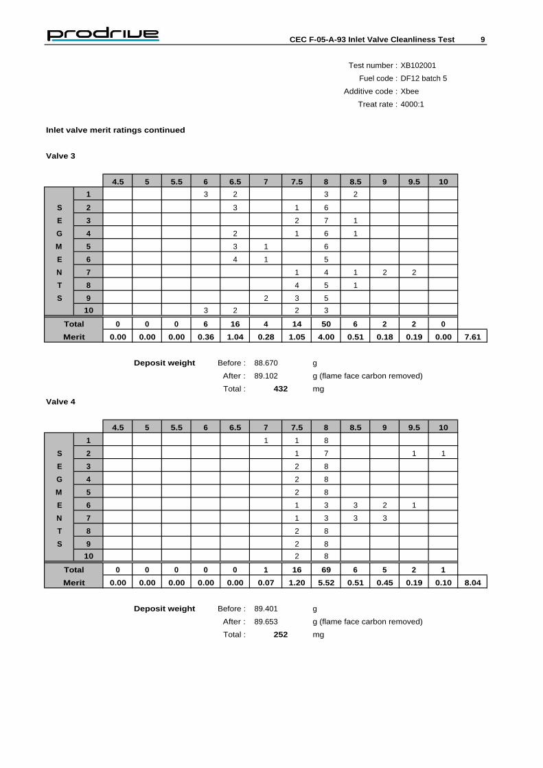
Inlet valve merit ratings continued
Valve 3
4.5 5 5.5 6 6.5 7 7.5 8 8.5 9 9.5 10
1 3 2 3 2
S 2 3 1 6
E 3 2 7 1
G 4 2 1 6 1
M 5 3 1 6
E 6 4 1 5
N 7 1 4 1 2 2
T 8 4 5 1
S 9 2 3 5
10 3 2 2 3
Total 0 0 0 6 16 4 14 50 6 2 2 0
Merit 0.00 0.00 0.00 0.36 1.04 0.28 1.05 4.00 0.51 0.18 0.19 0.00 7.61
Deposit weight Before : 88.670 g
After : 89.102 g (flame face carbon removed)
Total : 432 mg
Valve 4
4.5 5 5.5 6 6.5 7 7.5 8 8.5 9 9.5 10
1 1 1 8
S 2 1 7 1 1
E 3 2 8
G 4 2 8
M 5 2 8
E 6 1 3 3 2 1
N 7 1 3 3 3
T 8 2 8
S 9 2 8
10 2 8
Total 0 0 0 0 0 1 16 69 6 5 2 1
Merit 0.00 0.00 0.00 0.00 0.00 0.07 1.20 5.52 0.51 0.45 0.19 0.10 8.04
Deposit weight Before : 89.401 g
After : 89.653 g (flame face carbon removed)
Total : 252 mg

CEC F-05-A-93 Inlet Valve Cleanliness Test 10
Test number : XB102001
Fuel code : DF12 batch 5
Additive code : Xbee
Inlet valve photography Treat rate : 4000:1
Valve 1 Valve 2
Front (Injector side)
Back
Valve 3 Valve 4
Front
Back

CEC F-05-A-93 Inlet Valve Cleanliness Test 11
Unscheduled shutdown and deviations
Unscheduled shutdowns
Test Time off Reason for shutdown
hours test
None
Deviations
Test Duration Max Name of 'out of spec' parameter
Hours deviation

M-102-E Intake Valve Deposit Test
Test procedure : CEC F-05-A-93
Test Number : XB102002
Client : Xbee
Client Address : Avenue de Bielefeld Senne
29900 Concarneau
France
Client Distribution : Ronan Pennec
Client Order Number : 30003016800020600000
Fuel Code : DF12 batch 5
Test Fuel Received Date : 14-Jul-05
Additive Code : Xbee
Treat Rate : 4000:1
Test Additive Received Date : 11-Jul-05
Test Oil : RL223
Test Complete Date : 04-Aug-05
Project Engineer : G.Polkinghorne

CEC F-05-A-93 Inlet Valve Cleanliness Test 1
Contents
1. Introduct ion . .. 2
2. Test descript ion .. ..2
2.1 Test engine ... . ..2
2.2 Engine preparat ion . . .2
2.3 Test procedure .. .. ..2
2.4 Operat ing parameters .. ..3
2.5 End of test assessment 3
2.6 Pre-test checks .4
3. Results . .4
3.1 Results summary . .5
3.2 Emissions summary .6
3.3 Averaged operat ional data 7
3.4 Inlet valve merit rat ings ..8,9
3.5 Inlet valve photography .10
4. Unscheduled occurences ... 11

CEC F-05-A-93 Inlet Valve Cleanliness Test 2
Test description
The engine
Bore/Stroke - 95.50 / 80.25 mm
Swept Volume - 2299 cc
Compression Ratio - 9.0 : 1
Maximum Power - 100kW @ 5100 rev/min
Engine preparation
Test procedure
The engine is mounted on a test stand and operated for 800 cycles, totalling 60 hours. The cycle consists of four stages and is designed to represent urban driving conditions. Ignition advance and exhaust CO content are set prior to the start of the test.
The test engine is fitted with a cleaned cylinder head, which in turn has been fitted with new inlet valves. The inlet valves are pegged to prevent rotation. Fresh oil and a new oil filter are used for each test.
The procedure utilises a Mercedes-Benz M102.982 four cylinder, four stroke 2.3 litre gasoline engine. The engine is equipped with Bosch KE-Jetronic fuel injection equipment and has the following specification :-
This test method is designed to evaluate the propensity of gasoline or gasoline additive formulations to prevent inlet valve deposits in fuel injected engines. Results of tests run under this method are presented as the weight of the inlet valve deposit and as a merit rating based on a scale from 4.5 (extremely heavy inlet valve deposits) to 10 (clean inlet valve). Gasolines giving satisfactory performance in this test will possibly give enhanced protection against the formation of inlet valve deposits when utilised in four stroke gasoline fuelled engines.

CEC F-05-A-93 Inlet Valve Cleanliness Test 3
Test procedure continued
Stage Time Speed Torque
(secs) (rev/min) (Nm)
1 30 800 ± 30 <5.0
2 60 1300 ± 30 29.4
3 120 1850 ± 30 32.5
4 60 3000 ± 30 35
Operating parameters
Parameter Temperature (°C)
Coolant outlet 85 to 95
Oil gallery 90 to 105
Air inlet 25 to 35
End of test assessment
At the end of the test the cylinder head is dismounted from the engine and the valves carefully removed. The weight of deposit on the back of each valve is determined. The valves are then subjected to a visual rating against a photographic reference scale.

CEC F-05-A-93 Inlet Valve Cleanliness Test 4
Pre-test checks
Engine Warm-up
Duration Speed Torque
(mins) rpm Nm
4 1500 0
6 3000 0
CO content at idle checked and reset to: 0.57 (0.5 to 1.0 %)
EBP at Stage 4 checked and reset to: 0.18 (10 to 25 mbar)
Ignition timing 13 (15 ± 3 ° BTDC)
Blow-by @ 3000 rev/min (Stage 4) 8 <20l/min
Compressions
Cylinder number 1 2 3 4
Speed (rev/min) 220 217 235 224
Pressure (bar) 12.5 12.5 13.0 12.5
Specification : > 12 bar with a differential of < 1 bar between cylinder at 170 rev min.
The following pre-test check run was completed during which ignition timing was checked and reset as necessary. Once the test was on cycle exhaust back pressure was set at stage 4 and blow-by was measured.

CEC F-05-A-93 Inlet Valve Cleanliness Test 5
Test number : XB102002
Fuel code : DF12 batch 5
Additive code : Xbee
Treat rate : 4000:1
Results summary
Engine number : TK-M102E-02-02
Total engine hours : 600
Test stand number : 7
Total test fuel consumption : 215 Litres
Total test oil consumption : 155 gm
Inlet valve deposit weights
Deposits
Valve number 1 2 3 4 Average
Deposit weight 364 540 475 499 469.50
Inlet valve merit ratings
Merit rating
Valve number 1 2 3 4 Average
Merit Rating 7.42 7.18 7.33 6.96 7.22
CEC F-05-A-93 Inlet Valve Cleanliness Test 6
Test number : XB102002
Fuel code : DF12 batch 5
Additive code : Xbee
Treat rate : 4000:1
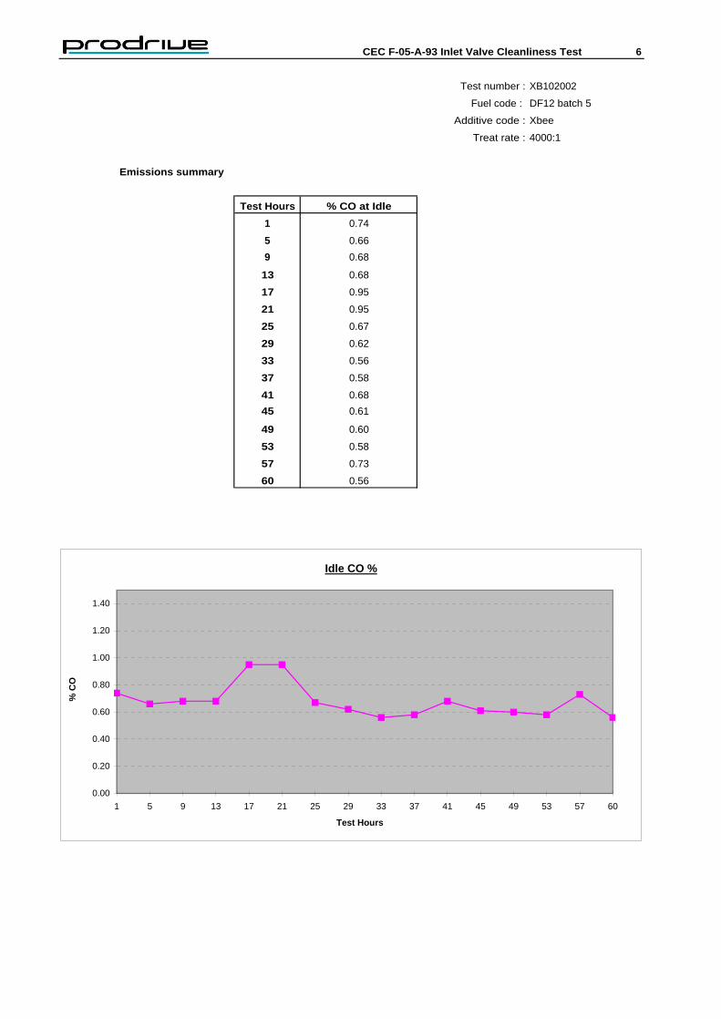
Emissions summary
Test Hours % CO at Idle
1 0.74
5 0.66
9 0.68
13 0.68
17 0.95
21 0.95
25 0.67
29 0.62
33 0.56
37 0.58
41 0.68
45 0.61
49 0.60
53 0.58
57 0.73
60 0.56
Idle CO %
0.00
0.20
0.40
0.60
0.80
1.00
1.20
1.40
1 5 9 13 17 21 25 29 33 37 41 45 49 53 57 60
% C
O
Test Hours

CEC F-05-A-93 Inlet Valve Cleanliness Test 7
Test number : XB102002
Fuel code : DF12 batch 5
Additive code : Xbee
Treat rate : 4000:1
Averaged operational data for each stage of the test cycle
Stage 1
Engine Engine Fuel Water Oil Air Inlet Exhaust temperatures
speed load cons. out sump inlet depn. Cyl. 1 Cyl. 2 Cyl 3 Cyl 4
rev/min Nm kg/hr °C °C °C mbar °C °C °C °C
Min 752 0.6 0.68 85 94 25 679 435 444 438 450
Max 849 0.9 0.96 95 102 33 736 560 599 567 569
Average 842 0.8 0.82 93 96 29 715 535 560 536 530
Stage 2
Engine Engine Fuel Water Oil Air Inlet Exhaust temperatures
speed load cons. out sump inlet depn. Cyl 1 Cyl 2 Cyl 3 Cyl 4
rev/min Nm kg/hr °C °C °C mbar °C °C °C °C
Min 1304 29.1 1.60 85 93 25 609 532 547 531 536
Max 1307 29.6 1.97 93 102 32 631 585 595 593 600
Average 1305 29.3 1.76 90 95 29 622 567 580 566 570
Stage 3
Engine Engine Fuel Water Oil Air Inlet Exhaust temperatures
speed load cons. out sump inlet depn. Cyl 1 Cyl 2 Cyl 3 Cyl 4
rev/min Nm kg/hr °C °C °C mbar °C °C °C °C
Min 1849 32.2 2.55 86 90 26 605 615 602 590 608
Max 1852 32.8 2.86 93 98 32 621 645 647 628 643
Average 1850 32.5 2.75 90 92 29 613 634 633 614 628
Stage 4
Engine Engine Fuel Water Oil Air Inlet Exhaust temperatures
speed load cons. out sump inlet depn. Cyl 1 Cyl 2 Cyl 3 Cyl 4
rev/min Nm kg/hr °C °C °C mbar °C °C °C °C
Min 2978 34.8 4.41 89 91 27 594 709 709 715 705
Max 2998 35.2 4.68 94 98 33 612 750 775 752 743
Average 2996 35.0 4.51 92 93 29 604 730 747 732 714
According to procedure CEC F-05-A-93 this test is deemed to be valid.

CEC F-05-A-93 Inlet Valve Cleanliness Test 8
Test number : XB102002
Fuel code : DF12 batch 5
Additive code : Xbee
Treat rate : 4000:1
Inlet valve merit ratings
Valve 1
4.5 5 5.5 6 6.5 7 7.5 8 8.5 9 9.5 10
1 3 3 3 1
S 2 3 6 1
E 3 5 4 1
G 4 6 3 1
M 5 6 2 1 1
E 6 4 1 3 1 1
N 7 6 1 1 1 1
T 8 4 2 2 1 1
S 9 4 3 2 1
10 3 3 3 1
Total 0 0 0 10 10 28 17 25 0 4 6 0
Merit 0.00 0.00 0.00 0.60 0.65 1.96 1.28 2.00 0.00 0.36 0.57 0.00 7.42
Deposit weight Before : 90.624 g
After : 90.988 g (flame face carbon removed)
Total : 364 mg
Valve 2
4.5 5 5.5 6 6.5 7 7.5 8 8.5 9 9.5 10
1 7 2 1
S 2 6 3 1
E 3 7 2 1
G 4 3 5 1 1
M 5 3 5 1 1
E 6 4 2 2 1 1
N 7 4 2 2 1 1
T 8 1 4 4 1
S 9 2 3 4 1
10 5 4 1
Total 0 0 8 0 13 46 23 0 0 0 10 0
Merit 0.00 0.00 0.44 0.00 0.85 3.22 1.73 0.00 0.00 0.00 0.95 0.00 7.18
Deposit Weight Before : 90.498 g
After : 91.038 g (flame face carbon removed)
Total : 540 mg

CEC F-05-A-93 Inlet Valve Cleanliness Test 9
Test number : XB102002
Fuel code : DF12 batch 5
Additive code : Xbee
Treat rate : 4000:1
Inlet valve merit ratings continued
Valve 3
4.5 5 5.5 6 6.5 7 7.5 8 8.5 9 9.5 10
1 8 1 1
S 2 9 1
E 3 9 1
G 4 9 1
M 5 3 5 1 1
E 6 3 4 2 1
N 7 2 4 3 1
T 8 2 5 3
S 9 1 4 3 1 1
10 2 5 2 1
Total 0 0 0 3 42 11 13 14 3 7 7 0
Merit 0.00 0.00 0.00 0.18 2.73 0.77 0.98 1.12 0.26 0.63 0.67 0.00 7.33
Deposit weight Before : 90.802 g
After : 91.277 g (flame face carbon removed)
Total : 475 mg
Valve 4
4.5 5 5.5 6 6.5 7 7.5 8 8.5 9 9.5 10
1 7 2 1
S 2 9 1
E 3 2 7 1
G 4 4 5 1
M 5 5 4 1
E 6 3 3 3 1
N 7 3 3 3 1
T 8 5 4 1
S 9 5 4 1
10 7 2 1
Total 0 0 0 14 38 25 13 0 0 6 4 0
Merit 0.00 0.00 0.00 0.84 2.47 1.75 0.98 0.00 0.00 0.54 0.38 0.00 6.96
Deposit weight Before : 91.352 g
After : 91.851 g (flame face carbon removed)
Total : 499 mg

CEC F-05-A-93 Inlet Valve Cleanliness Test 10
Test number : XB102002
Fuel code : DF12 batch 5
Additive code : Xbee
Inlet valve photography Treat rate : 4000:1
Valve 1 Valve 2
Front (Injector side) Front (Injector side)
Back Back
Valve 3 Valve 4
Front Front
Back Back

CEC F-05-A-93 Inlet Valve Cleanliness Test 11
Unscheduled shutdown and deviations
Unscheduled shutdowns
Test Time off Reason for shutdown
hours test
None
Deviations
Test Duration Max Name of 'out of spec' parameter
Hours deviation
Recommended