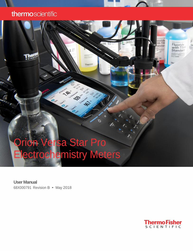
Orion Versa Star Pro Electrochemistry Meters
User Manual
68X000791 Revision B • May 2018

Table of Contents
Chapter 1 ....................................................................................................................... 6
Meter Introduction ........................................................................................................ 6
Meter Overview ............................................................................................................................ 6 Packing List ................................................................................................................................. 7 Intended Use ............................................................................................................................... 7
Chapter 2 ....................................................................................................................... 8
Meter Basics ................................................................................................................. 8
Using the Universal Power Adapter ............................................................................................. 8 Attaching the Electrode Stand ..................................................................................................... 9 Meter Connections ..................................................................................................................... 10 Meter Keypad ............................................................................................................................ 11
Function Keys .................................................................................................................. 12 Numeric Keypad ............................................................................................................... 12
Measurement Modules .............................................................................................................. 13 Module Measurement Capabilities ................................................................................... 13 Preconfigured Meter and Module Options ........................................................................ 13 Inserting and Removing Modules ..................................................................................... 14 Module Removal .............................................................................................................. 14 Module Connections......................................................................................................... 15
Measurement Display Options ................................................................................................... 16 Single, Dual or Multiple Channel Displays........................................................................ 16 Measurement Display Examples ...................................................................................... 18 Additional Measurement Display Icons ............................................................................ 19 pH Electrode Condition Icon ............................................................................................. 20 Customizing the Display ................................................................................................... 21
Meter and Module Maintenance ................................................................................................ 21
Chapter 3 ..................................................................................................................... 22
Meter Setup Menus ..................................................................................................... 22
Main Setup Menu ....................................................................................................................... 22 Channel 1-4 Setup Menus ......................................................................................................... 24
Method Menu ................................................................................................................... 26 Mode Menu ...................................................................................................................... 28 Temperature Menu ........................................................................................................... 29
Instrument Settings Setup Menu................................................................................................ 32 Log View Menu .......................................................................................................................... 34
Data Log ........................................................................................................................... 34 Calibration Log ................................................................................................................. 35
Diagnostics Menu ...................................................................................................................... 36 System Access Menu ................................................................................................................ 37
Enabling the System Access Feature .............................................................................. 38 Logging into the Administrator Account ............................................................................ 42 Logging into Existing User Account .................................................................................. 43 Logging Out of Existing User Account .............................................................................. 43
Chapter 4 ..................................................................................................................... 44
pH, pH/ISE and pH/LogR Measurement Modules..................................................... 44
Connecting Electrodes to the Module ........................................................................................ 44 Channel 1-4 Setup Menus ......................................................................................................... 47
Mode Menus for pH, mV, Relative mV, ORP and ISE ...................................................... 47 pH Calibration ............................................................................................................................ 52
pH Calibration Editing....................................................................................................... 52 Relative mV Calibration ............................................................................................................. 54 ORP Calibration ......................................................................................................................... 55 ISE Calibration (pH/ISE Module Only) ....................................................................................... 56
ISE Calibration Editing ..................................................................................................... 56 Temperature Calibration ............................................................................................................ 57
ATC Probe Temperature Calibration ................................................................................ 57 Manual Temperature Entry ............................................................................................... 58 LogR Temperature Calibration (pH/LogR Module Only) .................................................. 59
Incremental Techniques (pH/ISE Module Only) ......................................................................... 61 Single Known Addition ..................................................................................................... 62 Double Known Addition .................................................................................................... 64 Single Known Subtraction ................................................................................................ 66 Double Known Subtraction ............................................................................................... 68 Single Analate Addition .................................................................................................... 70 Single Analate Subtraction ............................................................................................... 72
Chapter 5 ..................................................................................................................... 74
Conductivity Measurement Module .......................................................................... 74
Connecting Electrodes to the Module ........................................................................................ 74 Channel 1-4 Setup Menus ......................................................................................................... 75
Mode Menus for Conductivity, TDS, Salinity and Resistivity ............................................ 75 Conductivity Calibration ............................................................................................................. 80
Automatic or Direct Conductivity Calibration .................................................................... 80 Cell Constant Entry (Manual Conductivity Calibration) ..................................................... 82
Conductivity Verification Procedure ........................................................................................... 83
Chapter 6 ..................................................................................................................... 84
RDO/DO Measurement Module .................................................................................. 84
Connecting Electrodes to the Module ........................................................................................ 84 Channel 1-4 Setup Menus ......................................................................................................... 85
Mode Menus for Dissolved Oxygen ................................................................................. 85 RDO Electrode Information .............................................................................................. 86
Dissolved Oxygen Calibration .................................................................................................... 87 Water Saturated Air Calibration ........................................................................................ 87 Air Saturated Water Calibration ........................................................................................ 88 Manual (Winkler) Calibration ............................................................................................ 88 Set Zero Calibration ......................................................................................................... 89
Chapter 7 ..................................................................................................................... 90
Meter Measurements .................................................................................................. 90
Measurement Overview ............................................................................................................. 90 Measurement Read Types ........................................................................................................ 92
Auto-Read ........................................................................................................................ 92 Timed ............................................................................................................................... 92 Single-Shot ....................................................................................................................... 93 Continuous ....................................................................................................................... 93
Measurement Procedure ........................................................................................................... 94
Measurement Tip – Using the Electrode Holder............................................................... 95
Chapter 8 ..................................................................................................................... 96
Data Transfer and Software Updates ........................................................................ 96
Data Transfer Settings ............................................................................................................... 96 Installing the Versa Star USB Driver Software ........................................................................... 98 Meter Software Upgrade Procedure .......................................................................................... 99 Computer and Printer Compatibility ......................................................................................... 101
Computer Requirements ................................................................................................ 101 Printer Requirements ..................................................................................................... 101
Versa Star Pro Meter Remote Control Protocols ..................................................................... 102 Remote Control Commands ........................................................................................... 102
Chapter 9 ................................................................................................................... 112
Customer Services ................................................................................................... 112
Troubleshooting Tips ............................................................................................................... 113 Meter Self-Test ............................................................................................................... 114
WEEE Compliance .................................................................................................................. 115 Declaration of Conformity ........................................................................................................ 115 Meter Specifications ................................................................................................................ 116 Ordering Information ................................................................................................................ 122
Versa Star Pro Meters and Versa Star Modules ............................................................ 122 Versa Star Pro Meter Accessories, Electrodes and Solutions ........................................ 126
Appendix A................................................................................................................ 128
Channel Specific Settings and Features ................................................................ 128
General Mode Settings ............................................................................................................ 128 Sample ID ...................................................................................................................... 128 Stability ........................................................................................................................... 129 Averaging ....................................................................................................................... 129 Alarms ............................................................................................................................ 129
pH and ISE Mode Settings ...................................................................................................... 130 Buffer Group and Automatic Buffer Recognition ............................................................ 130 Isopotential Value ........................................................................................................... 131 Linear Regression .......................................................................................................... 132 Blank Correction ............................................................................................................. 133 Low Level Stability ......................................................................................................... 134
LogR Temperature Technology ............................................................................................... 135 LogR Temperature Accuracy ......................................................................................... 135 Advanced pH Electrode Diagnostics using LogR Technology ....................................... 136
Conductivity, TDS, Salinity and Resistivity Mode Settings....................................................... 140 Cell Constant (K) and Automatic Conductivity Calibration ............................................. 140 Orion Conductivity Standard Values from 0 °C to 50 °C ................................................ 141 Reference Temperature, Temperature Compensation and Temperature Coefficient .... 143 Cell Type ........................................................................................................................ 144 TDS Factor ..................................................................................................................... 144 Salinity Type ................................................................................................................... 144
Dissolved Oxygen Settings ...................................................................................................... 145 Barometric Pressure Compensation .............................................................................. 145 Salinity Correction .......................................................................................................... 145
6 Orion Versa Star Pro Meter User Manual Thermo Scientific
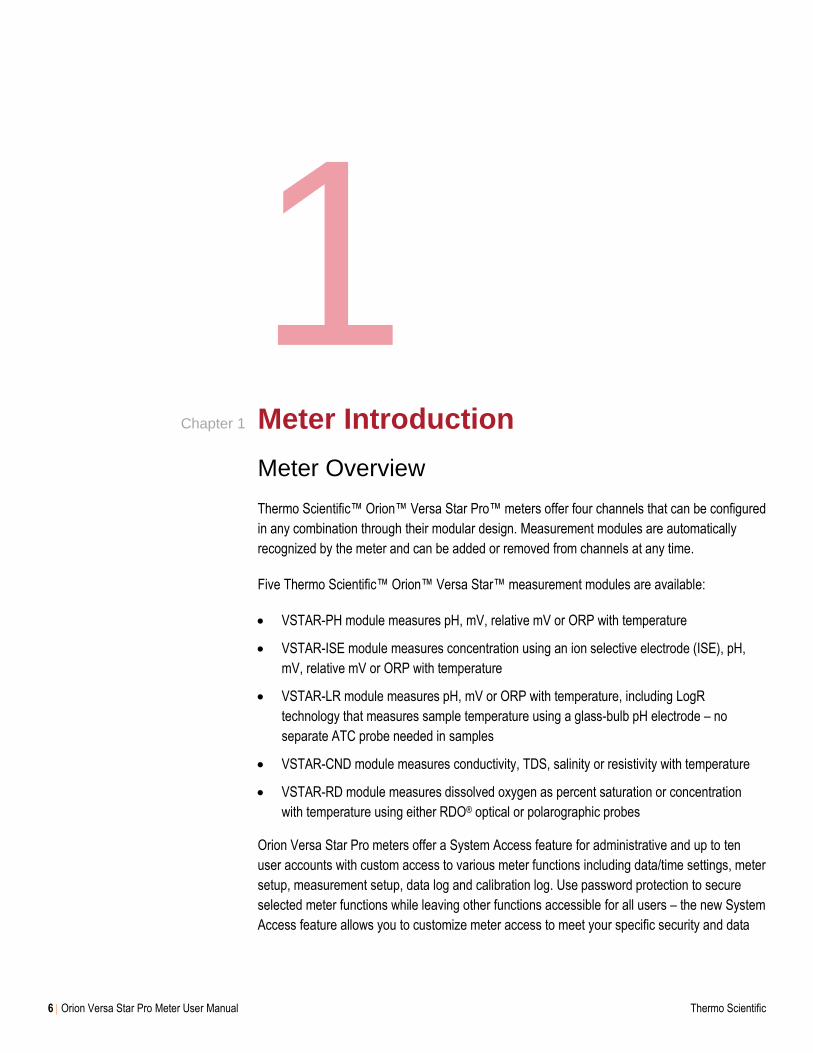
1 Meter Introduction
Meter Overview
Thermo Scientific™ Orion™ Versa Star Pro™ meters offer four channels that can be configured
in any combination through their modular design. Measurement modules are automatically
recognized by the meter and can be added or removed from channels at any time.
Five Thermo Scientific™ Orion™ Versa Star™ measurement modules are available:
VSTAR-PH module measures pH, mV, relative mV or ORP with temperature
VSTAR-ISE module measures concentration using an ion selective electrode (ISE), pH,
mV, relative mV or ORP with temperature
VSTAR-LR module measures pH, mV or ORP with temperature, including LogR
technology that measures sample temperature using a glass-bulb pH electrode – no
separate ATC probe needed in samples
VSTAR-CND module measures conductivity, TDS, salinity or resistivity with temperature
VSTAR-RD module measures dissolved oxygen as percent saturation or concentration
with temperature using either RDO® optical or polarographic probes
Orion Versa Star Pro meters offer a System Access feature for administrative and up to ten
user accounts with custom access to various meter functions including data/time settings, meter
setup, measurement setup, data log and calibration log. Use password protection to secure
selected meter functions while leaving other functions accessible for all users – the new System
Access feature allows you to customize meter access to meet your specific security and data
Chapter 1
Chapter 1 Meter Introduction
Thermo Scientific Orion Versa Star Pro Meter User Manual 7
reporting needs. The system access feature can easily be turned on or off as the needs of your
lab change for the ultimate flexibility in operation and ease-of-use.
Get the information you need quickly and easily from the large, bright color display, which can
be personalized to show only the measurements and information you need. Display one to four
measurements simultaneously in any combination.
When setting up the meter or performing a calibration, step-by-step instruction prompts and a
numeric keypad with menu-specific function keys make meter operation fast and simple. The
meter interface can be set to a variety of languages.
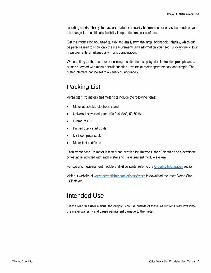
Packing List
Versa Star Pro meters and meter kits include the following items:
Meter-attachable electrode stand
Universal power adapter, 100-240 VAC, 50-60 Hz
Literature CD
Printed quick start guide
USB computer cable
Meter test certificate
Each Versa Star Pro meter is tested and certified by Thermo Fisher Scientific and a certificate
of testing is included with each meter and measurement module system.
For specific measurement module and kit contents, refer to the Ordering Information section.
Visit our website at www.thermofisher.com/orionsoftware to download the latest Versa Star
USB driver.
Intended Use
Please read this user manual thoroughly. Any use outside of these instructions may invalidate
the meter warranty and cause permanent damage to the meter.
8 Orion Versa Star Pro Meter User Manual Thermo Scientific
2 Meter Basics
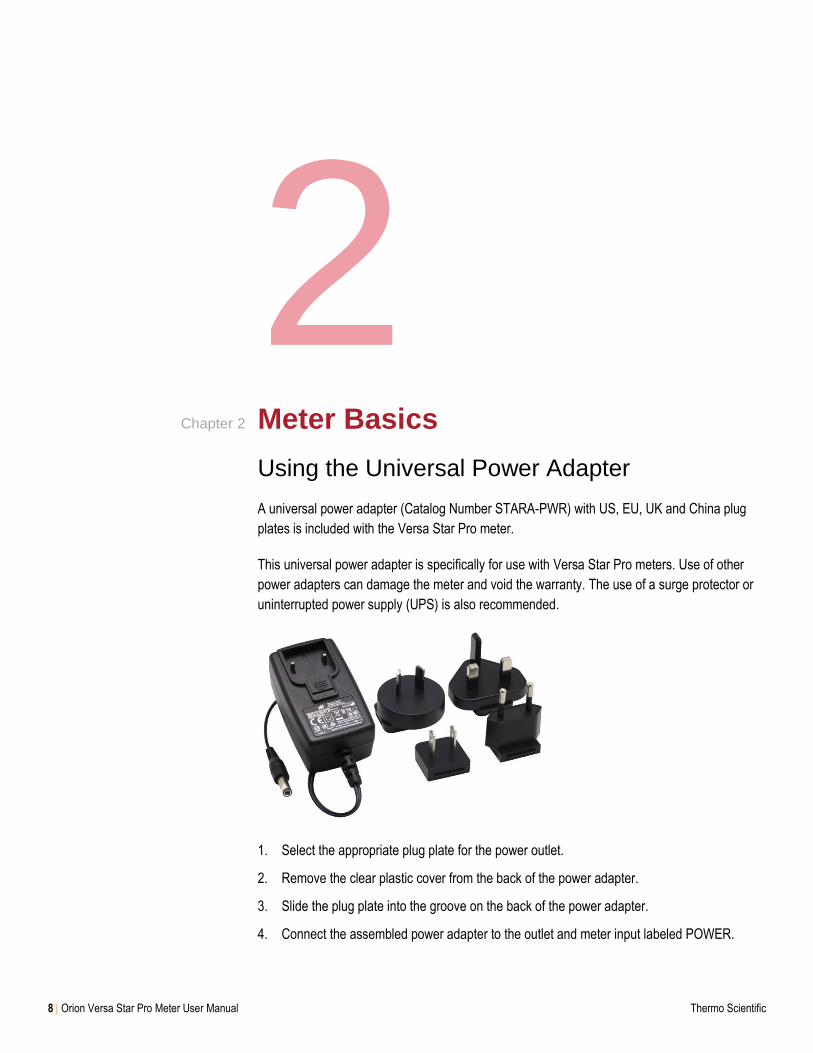
Using the Universal Power Adapter
A universal power adapter (Catalog Number STARA-PWR) with US, EU, UK and China plug
plates is included with the Versa Star Pro meter.
This universal power adapter is specifically for use with Versa Star Pro meters. Use of other
power adapters can damage the meter and void the warranty. The use of a surge protector or
uninterrupted power supply (UPS) is also recommended.
1. Select the appropriate plug plate for the power outlet.
2. Remove the clear plastic cover from the back of the power adapter.
3. Slide the plug plate into the groove on the back of the power adapter.
4. Connect the assembled power adapter to the outlet and meter input labeled POWER.
Chapter 2
Chapter 2 Meter Basics
Thermo Scientific Orion Versa Star Pro Meter User Manual 9
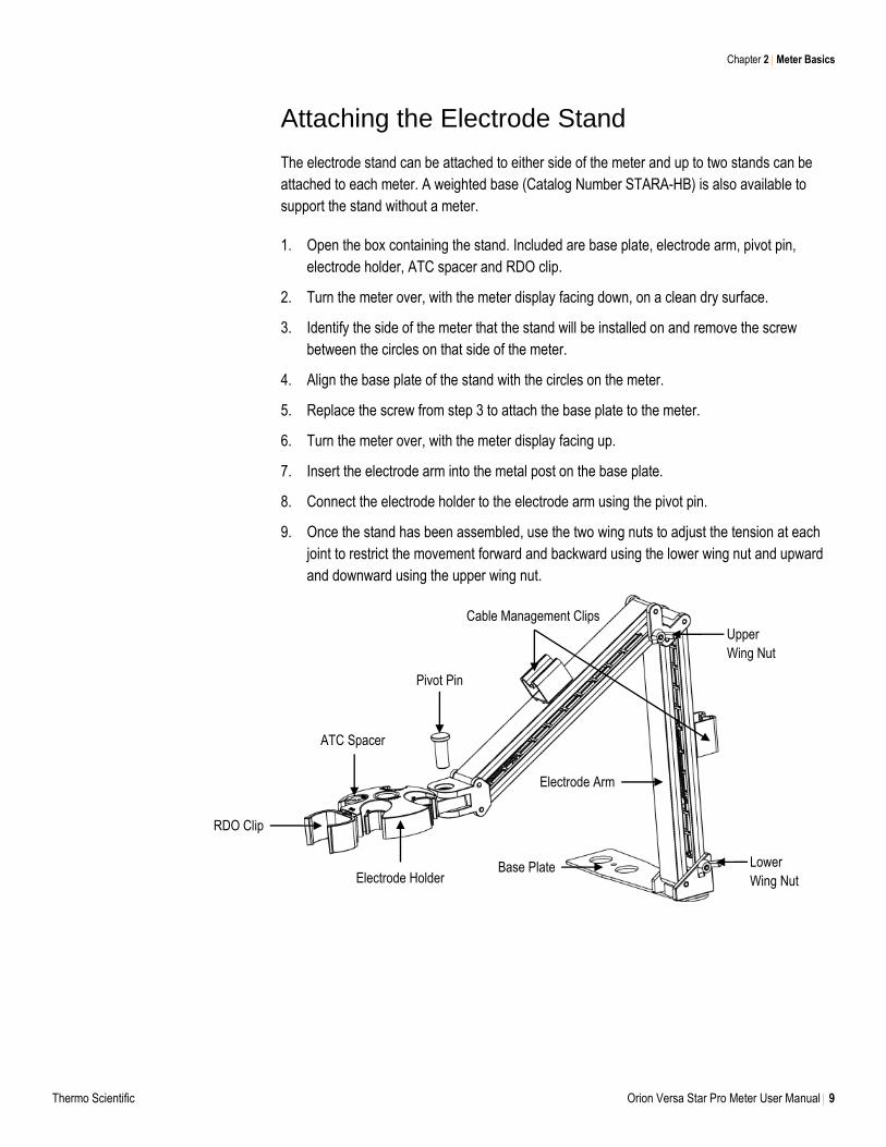
Attaching the Electrode Stand
The electrode stand can be attached to either side of the meter and up to two stands can be
attached to each meter. A weighted base (Catalog Number STARA-HB) is also available to
support the stand without a meter.
1. Open the box containing the stand. Included are base plate, electrode arm, pivot pin,
electrode holder, ATC spacer and RDO clip.
2. Turn the meter over, with the meter display facing down, on a clean dry surface.
3. Identify the side of the meter that the stand will be installed on and remove the screw
between the circles on that side of the meter.
4. Align the base plate of the stand with the circles on the meter.
5. Replace the screw from step 3 to attach the base plate to the meter.
6. Turn the meter over, with the meter display facing up.
7. Insert the electrode arm into the metal post on the base plate.
8. Connect the electrode holder to the electrode arm using the pivot pin.
9. Once the stand has been assembled, use the two wing nuts to adjust the tension at each
joint to restrict the movement forward and backward using the lower wing nut and upward
and downward using the upper wing nut.
Electrode Holder
Pivot Pin
ATC Spacer
Cable Management Clips
RDO Clip
Electrode Arm
Base Plate Lower
Wing Nut
Upper
Wing Nut
Chapter 2 Meter Basics
10 Orion Versa Star Pro Meter User Manual Thermo Scientific
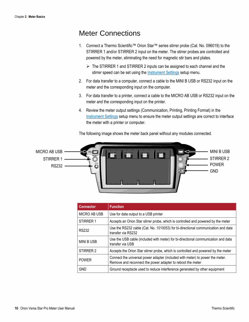
Meter Connections
1. Connect a Thermo Scientific™ Orion Star™ series stirrer probe (Cat. No. 096019) to the
STIRRER 1 and/or STIRRER 2 input on the meter. The stirrer probes are controlled and
powered by the meter, eliminating the need for magnetic stir bars and plates.
The STIRRER 1 and STIRRER 2 inputs can be assigned to each channel and the
stirrer speed can be set using the Instrument Settings setup menu.
2. For data transfer to a computer, connect a cable to the MINI B USB or RS232 input on the
meter and the corresponding input on the computer.
3. For data transfer to a printer, connect a cable to the MICRO AB USB or RS232 input on the
meter and the corresponding input on the printer.
4. Review the meter output settings (Communication, Printing, Printing Format) in the
Instrument Settings setup menu to ensure the meter output settings are correct to interface
the meter with a printer or computer.
The following image shows the meter back panel without any modules connected.
Connector Function
MICRO AB USB Use for data output to a USB printer
STIRRER 1 Accepts an Orion Star stirrer probe, which is controlled and powered by the meter
RS232 Use the RS232 cable (Cat. No. 1010053) for bi-directional communication and data
transfer via RS232
MINI B USB Use the USB cable (included with meter) for bi-directional communication and data
transfer via USB
STIRRER 2 Accepts the Orion Star stirrer probe, which is controlled and powered by the meter
POWER Connect the universal power adapter (included with meter) to power the meter.
Remove and reconnect the power adapter to reboot the meter
GND Ground receptacle used to reduce interference generated by other equipment
MINI B USB
STIRRER 2
POWER
GND
MICRO AB USB
STIRRER 1
RS232
Chapter 2 Meter Basics
Thermo Scientific Orion Versa Star Pro Meter User Manual 11
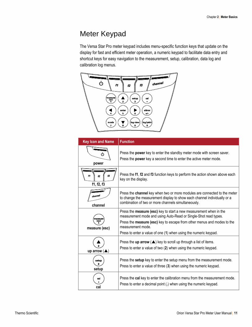
Meter Keypad
The Versa Star Pro meter keypad includes menu-specific function keys that update on the
display for fast and efficient meter operation, a numeric keypad to facilitate data entry and
shortcut keys for easy navigation to the measurement, setup, calibration, data log and
calibration log menus.
Key Icon and Name Function
power
Press the power key to enter the standby meter mode with screen saver.
Press the power key a second time to enter the active meter mode.
f1, f2, f3
Press the f1, f2 and f3 function keys to perform the action shown above each key on the display.
channel
Press the channel key when two or more modules are connected to the meter to change the measurement display to show each channel individually or a combination of two or more channels simultaneously.
measure (esc)
Press the measure (esc) key to start a new measurement when in the measurement mode and using Auto-Read or Single-Shot read types.
Press the measure (esc) key to escape from other menus and modes to the measurement mode.
Press to enter a value of one (1) when using the numeric keypad.
up arrow ()
Press the up arrow () key to scroll up through a list of items.
Press to enter a value of two (2) when using the numeric keypad.
setup
Press the setup key to enter the setup menu from the measurement mode.
Press to enter a value of three (3) when using the numeric keypad.
cal
Press the cal key to enter the calibration menu from the measurement mode.
Press to enter a decimal point (.) when using the numeric keypad.
Chapter 2 Meter Basics
12 Orion Versa Star Pro Meter User Manual Thermo Scientific
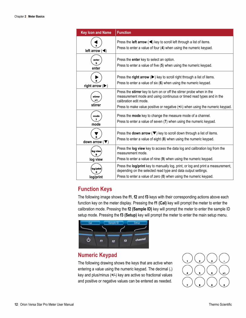
Key Icon and Name Function
left arrow ()
Press the left arrow () key to scroll left through a list of items.
Press to enter a value of four (4) when using the numeric keypad.
enter
Press the enter key to select an option.
Press to enter a value of five (5) when using the numeric keypad.
right arrow ()
Press the right arrow () key to scroll right through a list of items.
Press to enter a value of six (6) when using the numeric keypad.
stirrer
Press the stirrer key to turn on or off the stirrer probe when in the measurement mode and using continuous or timed read types and in the calibration edit mode.
Press to make value positive or negative (+/-) when using the numeric keypad.
mode
Press the mode key to change the measure mode of a channel.
Press to enter a value of seven (7) when using the numeric keypad.
down arrow ()
Press the down arrow () key to scroll down through a list of items.
Press to enter a value of eight (8) when using the numeric keypad.
log view
Press the log view key to access the data log and calibration log from the measurement mode.
Press to enter a value of nine (9) when using the numeric keypad.
log/print
Press the log/print key to manually log, print, or log and print a measurement, depending on the selected read type and data output settings.
Press to enter a value of zero (0) when using the numeric keypad.
Function Keys
The following image shows the f1, f2 and f3 keys with their corresponding actions above each
function key on the meter display. Pressing the f1 (Cal) key will prompt the meter to enter the
calibration mode. Pressing the f2 (Sample ID) key will prompt the meter to enter the sample ID
setup mode. Pressing the f3 (Setup) key will prompt the meter to enter the main setup menu.
Numeric Keypad
The following drawing shows the keys that are active when
entering a value using the numeric keypad. The decimal (.)
key and plus/minus (+/-) key are active so fractional values
and positive or negative values can be entered as needed.
Chapter 2 Meter Basics
Thermo Scientific Orion Versa Star Pro Meter User Manual 13
Measurement Modules
The Versa Star Pro meter has four channels that can be configured in any combination using
Versa Star measurement modules. The type of module connected to the channel will define the
measurement capability of that channel. Measurement modules are automatically recognized
by the meter and can be added or removed from a channel at any time. Five Versa Star
modules are available for pH, pH/ISE, pH/LogR, conductivity and dissolved oxygen.
Module Measurement Capabilities
The table below shows the module part number, module label shown on the top tab and
measure modes. All measure modes include the option to also measure temperature.
Module Catalog # VSTAR-PH VSTAR-ISE VSTAR-LR VSTAR-CND VSTAR-RD
Label pH pH/ISE pH/LogR Cond RDO/DO
Measure Modes
pH pH pH Conductivity % Saturation
mV mV mV TDS mg/L
RmV RmV RmV Salinity
ORP ORP ORP Resistivity
ISE
Temperature Modes
Automatic Automatic Automatic Automatic Automatic
Manual Manual Manual Manual
LogR
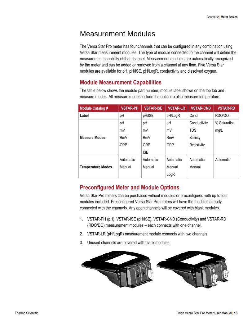
Preconfigured Meter and Module Options
Versa Star Pro meters can be purchased without modules or preconfigured with up to four
modules included. Preconfigured Versa Star Pro meters will have the modules already
connected with the channels. Any open channels will be covered with blank modules.
1. VSTAR-PH (pH), VSTAR-ISE (pH/ISE), VSTAR-CND (Conductivity) and VSTAR-RD
(RDO/DO) measurement modules – each connects with one channel.
2. VSTAR-LR (pH/LogR) measurement module connects with two channels.
3. Unused channels are covered with blank modules.
Chapter 2 Meter Basics
14 Orion Versa Star Pro Meter User Manual Thermo Scientific
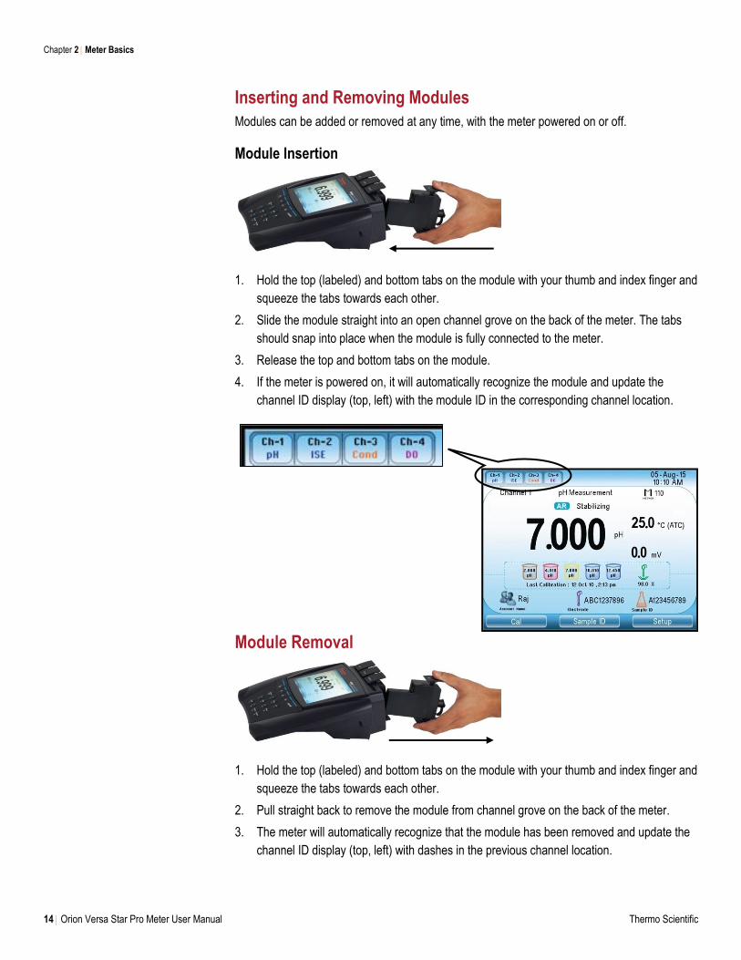
Inserting and Removing Modules
Modules can be added or removed at any time, with the meter powered on or off.
Module Insertion
1. Hold the top (labeled) and bottom tabs on the module with your thumb and index finger and
squeeze the tabs towards each other.
2. Slide the module straight into an open channel grove on the back of the meter. The tabs
should snap into place when the module is fully connected to the meter.
3. Release the top and bottom tabs on the module.
4. If the meter is powered on, it will automatically recognize the module and update the
channel ID display (top, left) with the module ID in the corresponding channel location.
Module Removal
1. Hold the top (labeled) and bottom tabs on the module with your thumb and index finger and
squeeze the tabs towards each other.
2. Pull straight back to remove the module from channel grove on the back of the meter.
3. The meter will automatically recognize that the module has been removed and update the
channel ID display (top, left) with dashes in the previous channel location.
Chapter 2 Meter Basics
Thermo Scientific Orion Versa Star Pro Meter User Manual 15
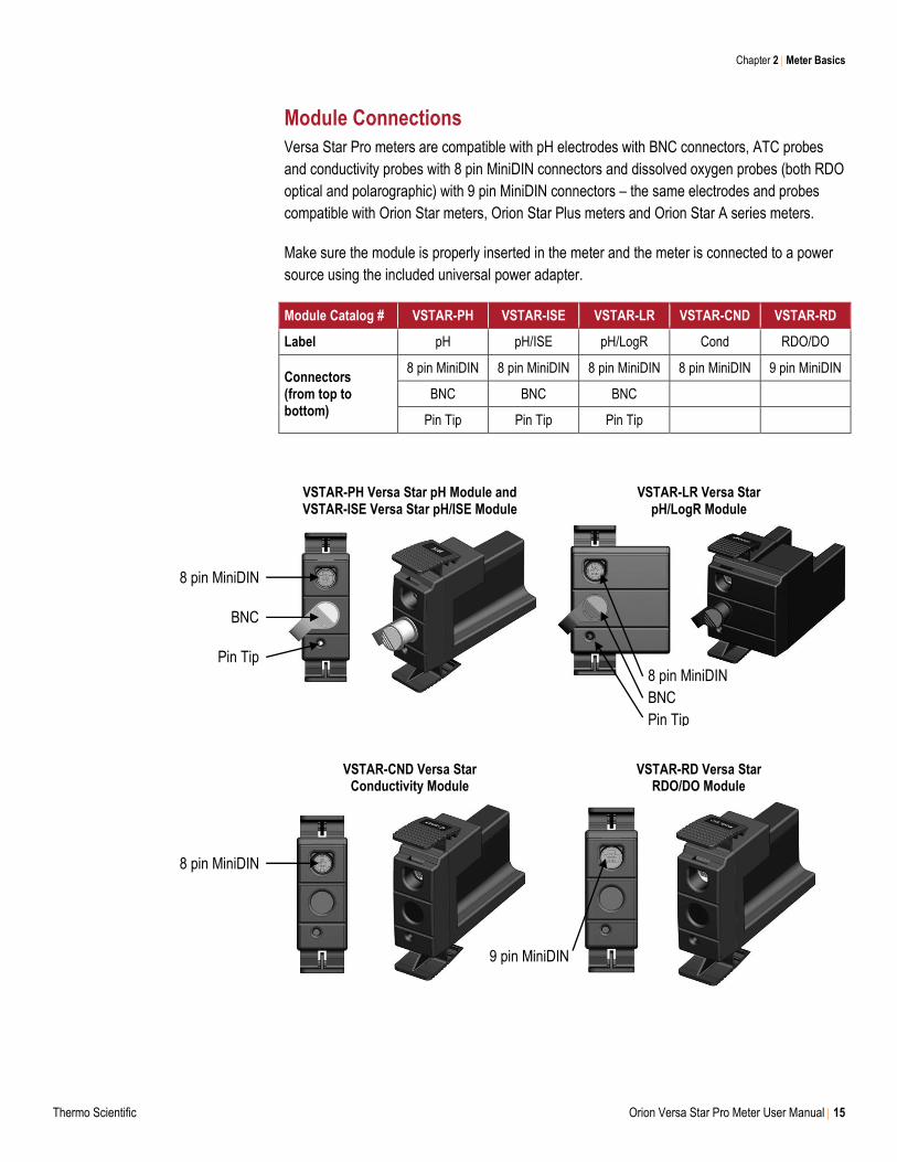
Module Connections
Versa Star Pro meters are compatible with pH electrodes with BNC connectors, ATC probes
and conductivity probes with 8 pin MiniDIN connectors and dissolved oxygen probes (both RDO
optical and polarographic) with 9 pin MiniDIN connectors – the same electrodes and probes
compatible with Orion Star meters, Orion Star Plus meters and Orion Star A series meters.
Make sure the module is properly inserted in the meter and the meter is connected to a power
source using the included universal power adapter.
Module Catalog # VSTAR-PH VSTAR-ISE VSTAR-LR VSTAR-CND VSTAR-RD
Label pH pH/ISE pH/LogR Cond RDO/DO
Connectors (from top to bottom)
8 pin MiniDIN 8 pin MiniDIN 8 pin MiniDIN 8 pin MiniDIN 9 pin MiniDIN
BNC BNC BNC
Pin Tip Pin Tip Pin Tip
VSTAR-PH Versa Star pH Module and VSTAR-ISE Versa Star pH/ISE Module
VSTAR-LR Versa Star pH/LogR Module
VSTAR-CND Versa Star Conductivity Module
VSTAR-RD Versa Star RDO/DO Module
8 pin MiniDIN
BNC
Pin Tip
8 pin MiniDIN
8 pin MiniDIN
BNC
Pin Tip
9 pin MiniDIN
Chapter 2 Meter Basics
16 Orion Versa Star Pro Meter User Manual Thermo Scientific
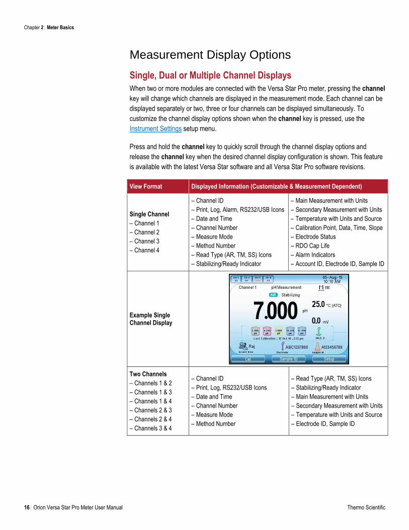
Measurement Display Options
Single, Dual or Multiple Channel Displays
When two or more modules are connected with the Versa Star Pro meter, pressing the channel
key will change which channels are displayed in the measurement mode. Each channel can be
displayed separately or two, three or four channels can be displayed simultaneously. To
customize the channel display options shown when the channel key is pressed, use the
Instrument Settings setup menu.
Press and hold the channel key to quickly scroll through the channel display options and
release the channel key when the desired channel display configuration is shown. This feature
is available with the latest Versa Star software and all Versa Star Pro software revisions.
View Format Displayed Information (Customizable & Measurement Dependent)
Single Channel
– Channel 1
– Channel 2
– Channel 3
– Channel 4
– Channel ID
– Print, Log, Alarm, RS232/USB Icons
– Date and Time
– Channel Number
– Measure Mode
– Method Number
– Read Type (AR, TM, SS) Icons
– Stabilizing/Ready Indicator
– Main Measurement with Units
– Secondary Measurement with Units
– Temperature with Units and Source
– Calibration Point, Data, Time, Slope
– Electrode Status
– RDO Cap Life
– Alarm Indicators
– Account ID, Electrode ID, Sample ID
Example Single Channel Display
Two Channels
– Channels 1 & 2
– Channels 1 & 3
– Channels 1 & 4
– Channels 2 & 3
– Channels 2 & 4
– Channels 3 & 4
– Channel ID
– Print, Log, RS232/USB Icons
– Date and Time
– Channel Number
– Measure Mode
– Method Number
– Read Type (AR, TM, SS) Icons
– Stabilizing/Ready Indicator
– Main Measurement with Units
– Secondary Measurement with Units
– Temperature with Units and Source
– Electrode ID, Sample ID
Chapter 2 Meter Basics
Thermo Scientific Orion Versa Star Pro Meter User Manual 17
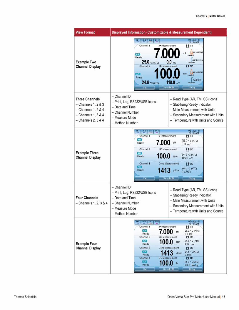
View Format Displayed Information (Customizable & Measurement Dependent)
Example Two Channel Display
Three Channels
– Channels 1, 2 & 3
– Channels 1, 2 & 4
– Channels 1, 3 & 4
– Channels 2, 3 & 4
– Channel ID
– Print, Log, RS232/USB Icons
– Date and Time
– Channel Number
– Measure Mode
– Method Number
– Read Type (AR, TM, SS) Icons
– Stabilizing/Ready Indicator
– Main Measurement with Units
– Secondary Measurement with Units
– Temperature with Units and Source
Example Three Channel Display
Four Channels
– Channels 1, 2, 3 & 4
– Channel ID
– Print, Log, RS232/USB Icons
– Date and Time
– Channel Number
– Measure Mode
– Method Number
– Read Type (AR, TM, SS) Icons
– Stabilizing/Ready Indicator
– Main Measurement with Units
– Secondary Measurement with Units
– Temperature with Units and Source
Example Four Channel Display
Chapter 2 Meter Basics
18 Orion Versa Star Pro Meter User Manual Thermo Scientific
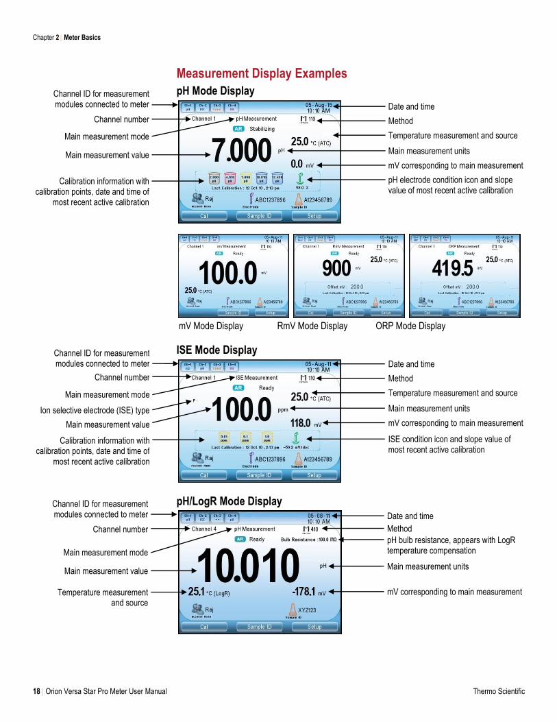
Measurement Display Examples
pH Mode Display
mV Mode Display RmV Mode Display ORP Mode Display
ISE Mode Display
pH/LogR Mode Display
Ion selective electrode (ISE) type
Calibration information with calibration points, date and time of
most recent active calibration
Main measurement mode
Main measurement value
Channel ID for measurement modules connected to meter
Channel number
Date and time
Method
Temperature measurement and source
Main measurement units
mV corresponding to main measurement
ISE condition icon and slope value of most recent active calibration
Date and time
Method
Temperature measurement and source
Main measurement units
mV corresponding to main measurement
pH electrode condition icon and slope value of most recent active calibration
Channel ID for measurement modules connected to meter
Channel number
Main measurement mode
Main measurement value
Calibration information with calibration points, date and time of
most recent active calibration
pH bulb resistance, appears with LogR temperature compensation
Date and time
Method
Main measurement units
mV corresponding to main measurement
Main measurement mode
Channel number
Channel ID for measurement modules connected to meter
Main measurement value
Temperature measurement and source
Chapter 2 Meter Basics
Thermo Scientific Orion Versa Star Pro Meter User Manual 19
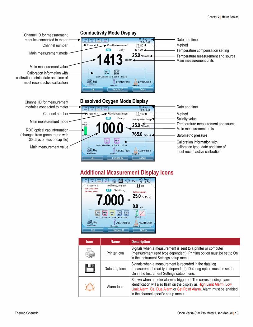
Conductivity Mode Display
Dissolved Oxygen Mode Display
Additional Measurement Display Icons
Icon Name Description
Printer Icon
Signals when a measurement is sent to a printer or computer (measurement read type dependent). Printing option must be set to On in the Instrument Settings setup menu.
Data Log Icon
Signals when a measurement is recorded in the data log (measurement read type dependent). Data log option must be set to On in the Instrument Settings setup menu.
Alarm Icon
Shown when a meter alarm is triggered. The corresponding alarm identification will also flash on the display as High Limit Alarm, Low Limit Alarm, Cal Due Alarm or Set Point Alarm. Alarm must be enabled in the channel-specific setup menu.
Channel ID for measurement modules connected to meter
Channel number
Date and time
Method
Main measurement units
Calibration information with calibration points, date and time of
most recent active calibration
Main measurement value
Main measurement mode
RDO optical cap information (changes from green to red with
30 days or less of cap life) Calibration information with calibration type, date and time of most recent active calibration
Main measurement value
Date and time
Barometric pressure
Channel ID for measurement modules connected to meter
Channel number
Main measurement mode Salinity value
Method
Temperature measurement and source
Temperature compensation setting
Temperature measurement and source Main measurement units
Chapter 2 Meter Basics
20 Orion Versa Star Pro Meter User Manual Thermo Scientific
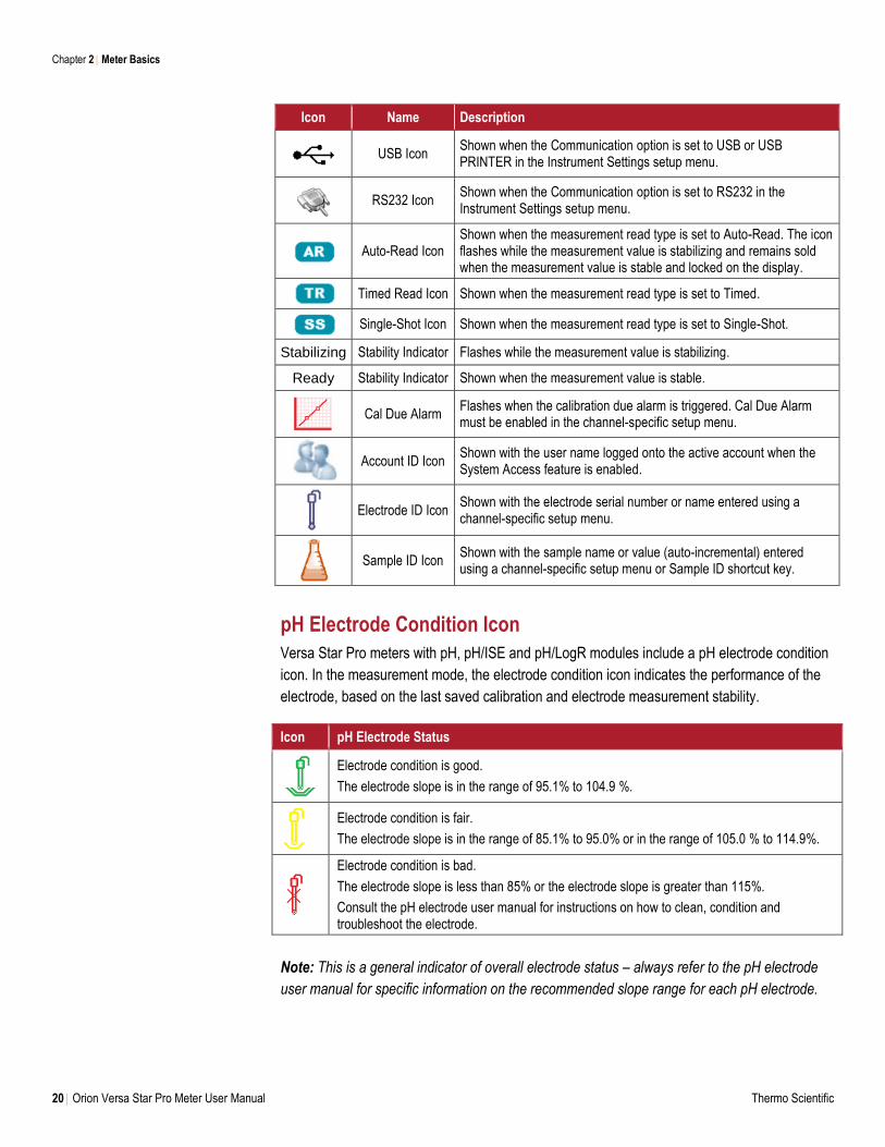
Icon Name Description
USB Icon
Shown when the Communication option is set to USB or USB PRINTER in the Instrument Settings setup menu.
RS232 Icon
Shown when the Communication option is set to RS232 in the Instrument Settings setup menu.
Auto-Read Icon
Shown when the measurement read type is set to Auto-Read. The icon flashes while the measurement value is stabilizing and remains sold when the measurement value is stable and locked on the display.
Timed Read Icon Shown when the measurement read type is set to Timed.
Single-Shot Icon Shown when the measurement read type is set to Single-Shot.
Stabilizing Stability Indicator Flashes while the measurement value is stabilizing.
Ready Stability Indicator Shown when the measurement value is stable.
Cal Due Alarm
Flashes when the calibration due alarm is triggered. Cal Due Alarm must be enabled in the channel-specific setup menu.
Account ID Icon
Shown with the user name logged onto the active account when the System Access feature is enabled.
Electrode ID Icon Shown with the electrode serial number or name entered using a channel-specific setup menu.
Sample ID Icon Shown with the sample name or value (auto-incremental) entered using a channel-specific setup menu or Sample ID shortcut key.
pH Electrode Condition Icon
Versa Star Pro meters with pH, pH/ISE and pH/LogR modules include a pH electrode condition
icon. In the measurement mode, the electrode condition icon indicates the performance of the
electrode, based on the last saved calibration and electrode measurement stability.
Icon pH Electrode Status
Electrode condition is good.
The electrode slope is in the range of 95.1% to 104.9 %.
Electrode condition is fair.
The electrode slope is in the range of 85.1% to 95.0% or in the range of 105.0 % to 114.9%.
Electrode condition is bad.
The electrode slope is less than 85% or the electrode slope is greater than 115%.
Consult the pH electrode user manual for instructions on how to clean, condition and troubleshoot the electrode.
Note: This is a general indicator of overall electrode status – always refer to the pH electrode
user manual for specific information on the recommended slope range for each pH electrode.
Chapter 2 Meter Basics
Thermo Scientific Orion Versa Star Pro Meter User Manual 21
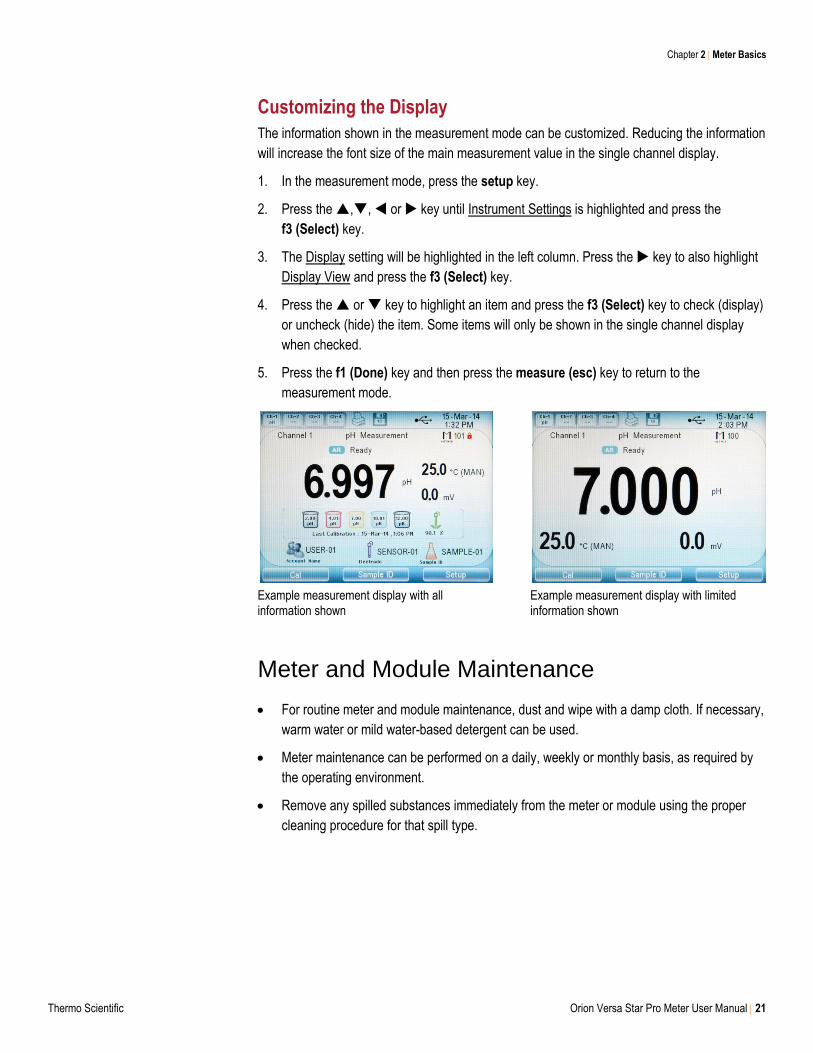
Customizing the Display
The information shown in the measurement mode can be customized. Reducing the information
will increase the font size of the main measurement value in the single channel display.
1. In the measurement mode, press the setup key.
2. Press the ,, or key until Instrument Settings is highlighted and press the
f3 (Select) key.
3. The Display setting will be highlighted in the left column. Press the key to also highlight
Display View and press the f3 (Select) key.
4. Press the or key to highlight an item and press the f3 (Select) key to check (display)
or uncheck (hide) the item. Some items will only be shown in the single channel display
when checked.
5. Press the f1 (Done) key and then press the measure (esc) key to return to the
measurement mode.
Example measurement display with all information shown
Example measurement display with limited information shown
Meter and Module Maintenance
For routine meter and module maintenance, dust and wipe with a damp cloth. If necessary,
warm water or mild water-based detergent can be used.
Meter maintenance can be performed on a daily, weekly or monthly basis, as required by
the operating environment.
Remove any spilled substances immediately from the meter or module using the proper
cleaning procedure for that spill type.
22 Orion Versa Star Pro Meter User Manual Thermo Scientific
3 Meter Setup Menus
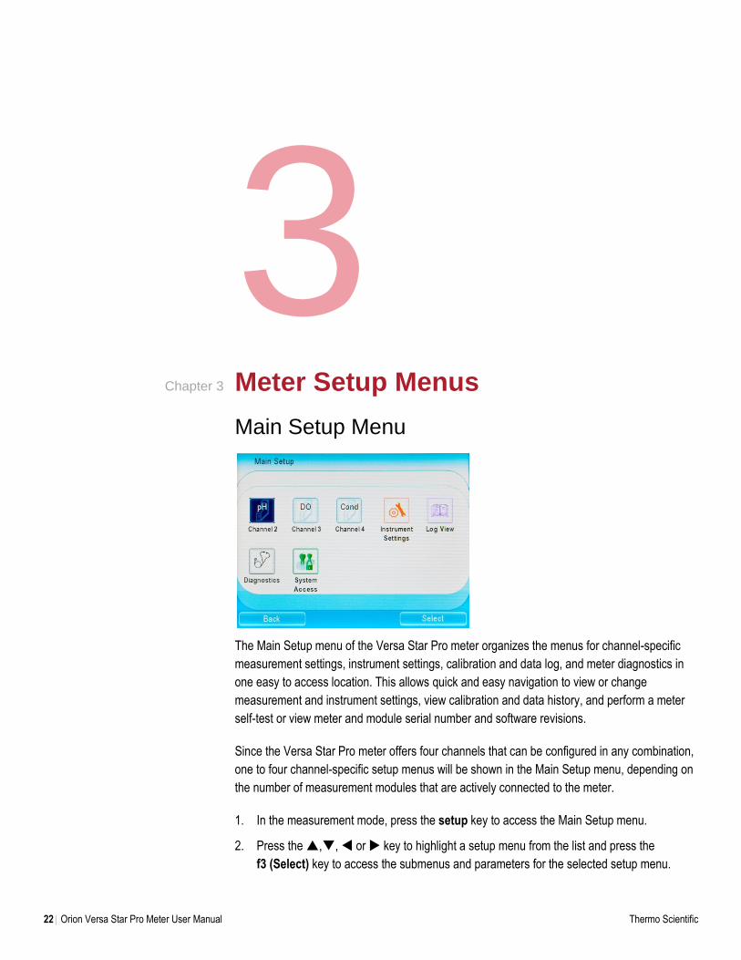
Main Setup Menu
The Main Setup menu of the Versa Star Pro meter organizes the menus for channel-specific
measurement settings, instrument settings, calibration and data log, and meter diagnostics in
one easy to access location. This allows quick and easy navigation to view or change
measurement and instrument settings, view calibration and data history, and perform a meter
self-test or view meter and module serial number and software revisions.
Since the Versa Star Pro meter offers four channels that can be configured in any combination,
one to four channel-specific setup menus will be shown in the Main Setup menu, depending on
the number of measurement modules that are actively connected to the meter.
1. In the measurement mode, press the setup key to access the Main Setup menu.
2. Press the ,, or key to highlight a setup menu from the list and press the
f3 (Select) key to access the submenus and parameters for the selected setup menu.
Chapter 3
Chapter 3 Meter Setup Menus
Thermo Scientific Orion Versa Star Pro Meter User Manual 23
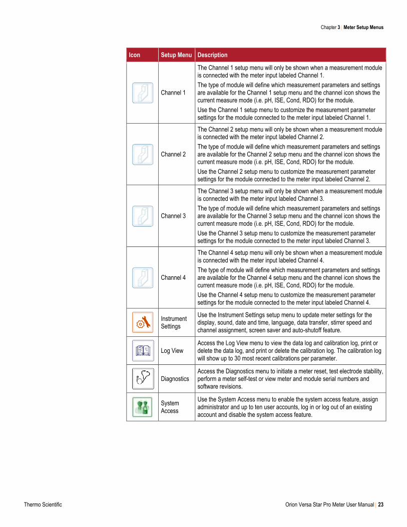
Icon Setup Menu Description
Channel 1
The Channel 1 setup menu will only be shown when a measurement module is connected with the meter input labeled Channel 1.
The type of module will define which measurement parameters and settings are available for the Channel 1 setup menu and the channel icon shows the current measure mode (i.e. pH, ISE, Cond, RDO) for the module.
Use the Channel 1 setup menu to customize the measurement parameter settings for the module connected to the meter input labeled Channel 1.
Channel 2
The Channel 2 setup menu will only be shown when a measurement module is connected with the meter input labeled Channel 2.
The type of module will define which measurement parameters and settings are available for the Channel 2 setup menu and the channel icon shows the current measure mode (i.e. pH, ISE, Cond, RDO) for the module.
Use the Channel 2 setup menu to customize the measurement parameter settings for the module connected to the meter input labeled Channel 2.
Channel 3
The Channel 3 setup menu will only be shown when a measurement module is connected with the meter input labeled Channel 3.
The type of module will define which measurement parameters and settings are available for the Channel 3 setup menu and the channel icon shows the current measure mode (i.e. pH, ISE, Cond, RDO) for the module.
Use the Channel 3 setup menu to customize the measurement parameter settings for the module connected to the meter input labeled Channel 3.
Channel 4
The Channel 4 setup menu will only be shown when a measurement module is connected with the meter input labeled Channel 4.
The type of module will define which measurement parameters and settings are available for the Channel 4 setup menu and the channel icon shows the current measure mode (i.e. pH, ISE, Cond, RDO) for the module.
Use the Channel 4 setup menu to customize the measurement parameter settings for the module connected to the meter input labeled Channel 4.
Instrument Settings
Use the Instrument Settings setup menu to update meter settings for the display, sound, date and time, language, data transfer, stirrer speed and channel assignment, screen saver and auto-shutoff feature.
Log View Access the Log View menu to view the data log and calibration log, print or delete the data log, and print or delete the calibration log. The calibration log will show up to 30 most recent calibrations per parameter.
Diagnostics Access the Diagnostics menu to initiate a meter reset, test electrode stability, perform a meter self-test or view meter and module serial numbers and software revisions.
System Access
Use the System Access menu to enable the system access feature, assign administrator and up to ten user accounts, log in or log out of an existing account and disable the system access feature.
Chapter 3 Meter Setup Menus
24 Orion Versa Star Pro Meter User Manual Thermo Scientific
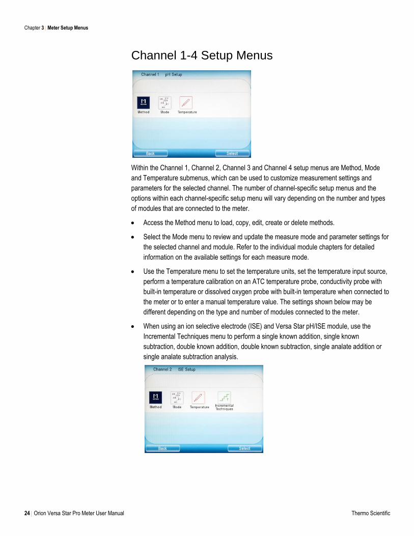
Channel 1-4 Setup Menus
Within the Channel 1, Channel 2, Channel 3 and Channel 4 setup menus are Method, Mode
and Temperature submenus, which can be used to customize measurement settings and
parameters for the selected channel. The number of channel-specific setup menus and the
options within each channel-specific setup menu will vary depending on the number and types
of modules that are connected to the meter.
Access the Method menu to load, copy, edit, create or delete methods.
Select the Mode menu to review and update the measure mode and parameter settings for
the selected channel and module. Refer to the individual module chapters for detailed
information on the available settings for each measure mode.
Use the Temperature menu to set the temperature units, set the temperature input source,
perform a temperature calibration on an ATC temperature probe, conductivity probe with
built-in temperature or dissolved oxygen probe with built-in temperature when connected to
the meter or to enter a manual temperature value. The settings shown below may be
different depending on the type and number of modules connected to the meter.
When using an ion selective electrode (ISE) and Versa Star pH/ISE module, use the
Incremental Techniques menu to perform a single known addition, single known
subtraction, double known addition, double known subtraction, single analate addition or
single analate subtraction analysis.
Chapter 3 Meter Setup Menus
Thermo Scientific Orion Versa Star Pro Meter User Manual 25
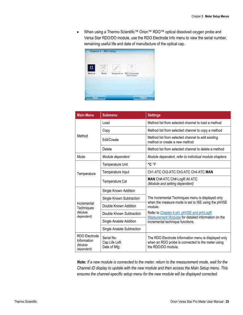
When using a Thermo Scientific™ Orion™ RDO™ optical dissolved oxygen probe and
Versa Star RDO/DO module, use the RDO Electrode Info menu to view the serial number,
remaining useful life and date of manufacture of the optical cap.
Main Menu Submenu Settings
Method
Load Method list from selected channel to load a method
Copy Method list from selected channel to copy a method
Edit/Create Method list from selected channel to edit existing method or create a new method
Delete Method list from selected channel to delete a method
Mode Module dependent Module dependent, refer to individual module chapters
Temperature
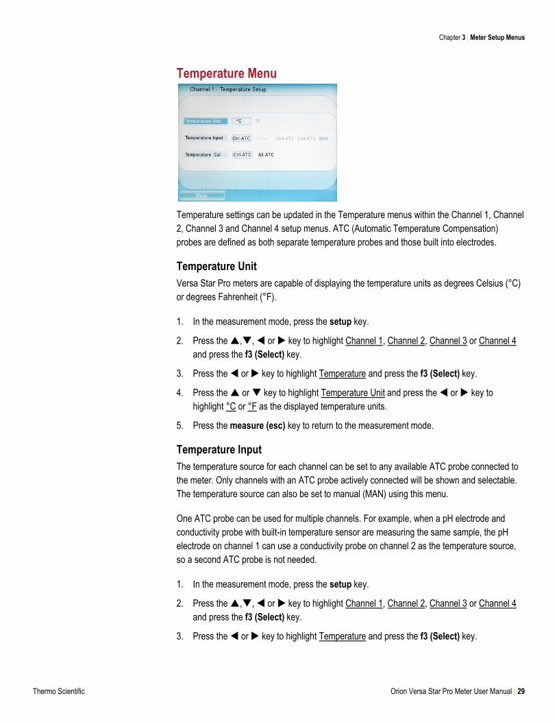
Temperature Unit °C °F
Temperature Input Ch1-ATC Ch2-ATC Ch3-ATC Ch4-ATC MAN
Temperature Cal MAN Ch#-ATC Ch#-LogR All ATC (Module and setting dependent)
Incremental Techniques (Module dependent)
Single Known Addition
The Incremental Techniques menu is displayed only when the measure mode is set to ISE using the pH/ISE module.
Refer to Chapter 4 pH, pH/ISE and pH/LogR Measurement Modules for detailed information on the incremental technique functions.
Single Known Subtraction
Double Known Addition
Double Known Subtraction
Single Analate Addition
Single Analate Subtraction
RDO Electrode Information (Module dependent)
Serial No: Cap Life Left: Date of Mfg:
The RDO Electrode Information menu is displayed only when an RDO probe is connected to the meter using the RDO/DO module.
Note: If a new module is connected to the meter, return to the measurement mode, wait for the
Channel ID display to update with the new module and then access the Main Setup menu. This
ensures the channel-specific setup menu for the new module will be displayed corrected.
Chapter 3 Meter Setup Menus
26 Orion Versa Star Pro Meter User Manual Thermo Scientific
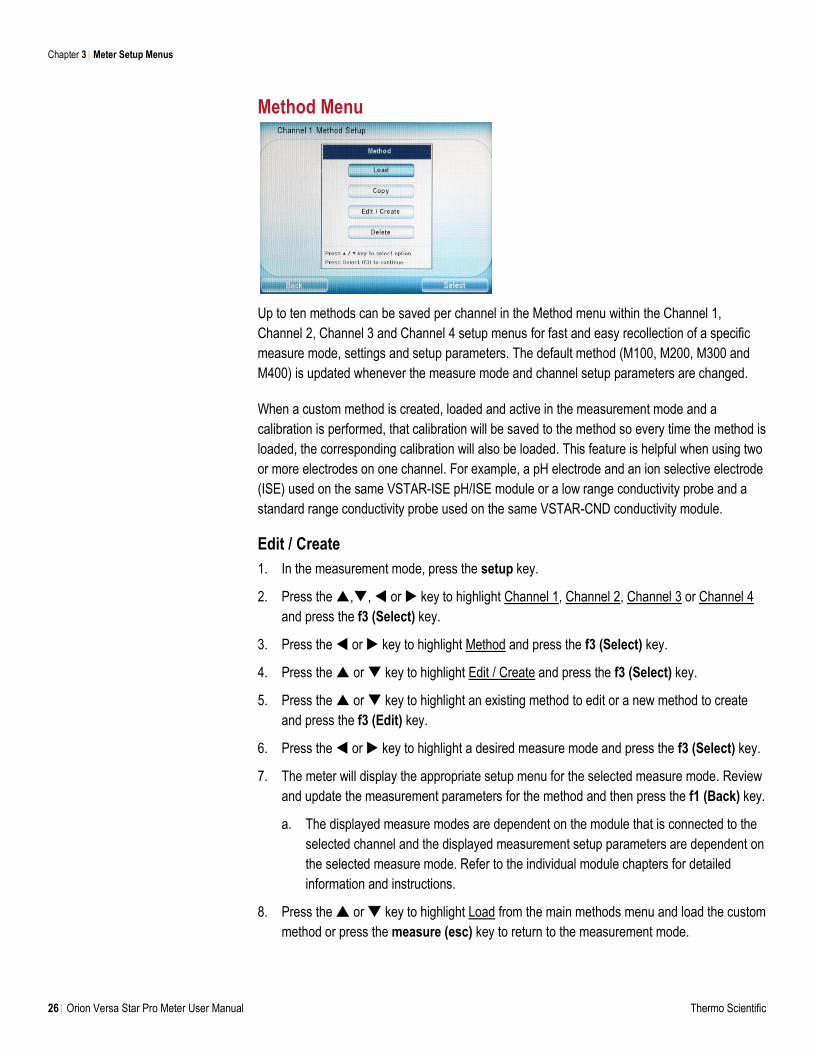
Method Menu
Up to ten methods can be saved per channel in the Method menu within the Channel 1,
Channel 2, Channel 3 and Channel 4 setup menus for fast and easy recollection of a specific
measure mode, settings and setup parameters. The default method (M100, M200, M300 and
M400) is updated whenever the measure mode and channel setup parameters are changed.
When a custom method is created, loaded and active in the measurement mode and a
calibration is performed, that calibration will be saved to the method so every time the method is
loaded, the corresponding calibration will also be loaded. This feature is helpful when using two
or more electrodes on one channel. For example, a pH electrode and an ion selective electrode
(ISE) used on the same VSTAR-ISE pH/ISE module or a low range conductivity probe and a
standard range conductivity probe used on the same VSTAR-CND conductivity module.
Edit / Create
1. In the measurement mode, press the setup key.
2. Press the ,, or key to highlight Channel 1, Channel 2, Channel 3 or Channel 4
and press the f3 (Select) key.
3. Press the or key to highlight Method and press the f3 (Select) key.
4. Press the or key to highlight Edit / Create and press the f3 (Select) key.
5. Press the or key to highlight an existing method to edit or a new method to create
and press the f3 (Edit) key.
6. Press the or key to highlight a desired measure mode and press the f3 (Select) key.
7. The meter will display the appropriate setup menu for the selected measure mode. Review
and update the measurement parameters for the method and then press the f1 (Back) key.
a. The displayed measure modes are dependent on the module that is connected to the
selected channel and the displayed measurement setup parameters are dependent on
the selected measure mode. Refer to the individual module chapters for detailed
information and instructions.
8. Press the or key to highlight Load from the main methods menu and load the custom
method or press the measure (esc) key to return to the measurement mode.
Chapter 3 Meter Setup Menus
Thermo Scientific Orion Versa Star Pro Meter User Manual 27
Load
Use the load function to activate a method for use in the measurement mode. If no custom
method has been created, the default method is active. Loading a blank method (date and time
shown as dashes on the method list) will activate the default measure mode and channel setup
parameters for that channel.
Copy
Use the copy function to duplicate an existing custom method (measure mode, settings and
setup parameters) to a new or different method. If two or more channels have the same
measurement capabilities (i.e. two channels with a pH module), then methods can be coped
between channels. Copying methods is a good way to preserve an original copy of a custom
method and then create a new custom method based on the previous method settings.
Delete
Use the delete function to reset an existing method to the default measure mode, settings and
setup parameters for the selected channel.
Chapter 3 Meter Setup Menus
28 Orion Versa Star Pro Meter User Manual Thermo Scientific
Mode Menu
1. In the measurement mode, press the setup key.
2. Press the ,, or key to highlight Channel 1, Channel 2, Channel 3 or Channel 4
and press the f3 (Select) key.
3. Press the or key to highlight Mode and press the f3 (Select) key.
4. The available measure modes will depend on the type of module connected with the
selected channel.
a. For the pH module, press the or key to highlight the pH, mV, Relative mV or
ORP measure mode and press the f3 (Select) key.
b. For the pH/ISE module, press the or key to highlight the pH, mV, Relative mV,
ORP or ISE measure mode and press the f3 (Select) key.
c. For the pH/LogR module, press the or key to highlight the pH, mV, Relative mV
or ORP measure mode and press the f3 (Select) key.
d. For the conductivity module, press the or key to highlight the conductivity, TDS,
Salinity or Resistivity measure mode and press the f3 (Select) key.
e. The RDO/DO module will proceed directly into the measure mode settings and setup
parameters menu.
5. Press the or key to highlight a menu option and press the or key to highlight a
submenu option. Common settings include Electrode Serial Number, Sample ID, Stability,
Averaging, Read Type and Alarm. Onscreen text prompts provide instructions for changing
parameters within a selected menu option.
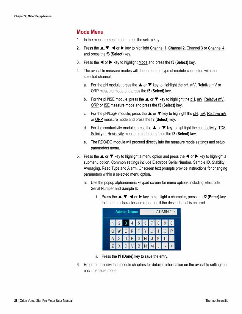
a. Use the popup alphanumeric keypad screen for menu options including Electrode
Serial Number and Sample ID.
i. Press the ,, or key to highlight a character, press the f2 (Enter) key
to input the character and repeat until the desired label is entered.
ii. Press the f1 (Done) key to save the entry.
6. Refer to the individual module chapters for detailed information on the available settings for
each measure mode.
Chapter 3 Meter Setup Menus
Thermo Scientific Orion Versa Star Pro Meter User Manual 29
Temperature Menu
Temperature settings can be updated in the Temperature menus within the Channel 1, Channel
2, Channel 3 and Channel 4 setup menus. ATC (Automatic Temperature Compensation)
probes are defined as both separate temperature probes and those built into electrodes.
Temperature Unit
Versa Star Pro meters are capable of displaying the temperature units as degrees Celsius (°C)
or degrees Fahrenheit (°F).
1. In the measurement mode, press the setup key.
2. Press the ,, or key to highlight Channel 1, Channel 2, Channel 3 or Channel 4
and press the f3 (Select) key.
3. Press the or key to highlight Temperature and press the f3 (Select) key.
4. Press the or key to highlight Temperature Unit and press the or key to
highlight °C or °F as the displayed temperature units.
5. Press the measure (esc) key to return to the measurement mode.
Temperature Input
The temperature source for each channel can be set to any available ATC probe connected to
the meter. Only channels with an ATC probe actively connected will be shown and selectable.
The temperature source can also be set to manual (MAN) using this menu.
One ATC probe can be used for multiple channels. For example, when a pH electrode and
conductivity probe with built-in temperature sensor are measuring the same sample, the pH
electrode on channel 1 can use a conductivity probe on channel 2 as the temperature source,
so a second ATC probe is not needed.
1. In the measurement mode, press the setup key.
2. Press the ,, or key to highlight Channel 1, Channel 2, Channel 3 or Channel 4
and press the f3 (Select) key.
3. Press the or key to highlight Temperature and press the f3 (Select) key.
Chapter 3 Meter Setup Menus
30 Orion Versa Star Pro Meter User Manual Thermo Scientific
4. Press the or key to highlight Temperature Input and press the or key to
highlight an available ATC probe (i.e. Ch2-ATC) as the temperature source or highlight
MAN for manual temperature input.
a. This setting will determine which options are available in the Temperature Cal menu.
5. Press the measure (esc) key to return to the measurement mode or proceed to Step 4 in
the Temperature Cal menu section.
Temperature Cal
A temperature calibration can be performed for individual ATC probes or simultaneously for all
ATC probes connected to the meter. A manual temperature value can also be entered using the
Temperature Cal menu if the MAN setting is selected in the Temperature Input menu.
The meter has a relative temperature accuracy of ±0.1°C. ATC probes have varying relative
temperature accuracies, usually ±0.5°C to ±2°C. Use the temperature calibration function only
when necessary. It is recommended that two NIST-traceable thermometers be used to measure
and verify the calibration solution temperature. Since the temperature offset calculated during
the calibration is applied to all future temperature measurements, recalibrate the temperature if
a different ATC probe is used.
ATC Probe Temperature Calibration
Prepare and connect all ATC probes to be calibrated to the appropriate module inputs on the
selected channels.
1. In the measurement mode, press the setup key.
2. Press the ,, or key to highlight Channel 1, Channel 2, Channel 3 or Channel 4
and press the f3 (Select) key.
3. Press the or key to highlight Temperature and press the f3 (Select) key.
4. Press the or key to highlight Temperature Cal and press the or key to highlight
the individual ATC probe selected in the Temperature Input menu (i.e. Ch2-ATC) or All
ATC and press the f3 (Select) key.
5. Place the ATC probes into a solution with a known, stable temperature. It is recommended
that two NIST-traceable thermometers be used to measure and verify the temperature.
6. Press the f3 (Edit) key, use the numeric keypad to enter the temperature of the solution
and press the f2 (Accept) key to save the temperature value and update the offset.
7. If applicable, press the or key to highlight the reference temperature of the next ATC
probe and repeat steps 3 and 4 for each ATC probe connected to the meter.
8. Once all ATC probes are calibrated, press the f1 (Back) key to exit the calibration and
press the measure (esc) key to return to the measurement mode.
Chapter 3 Meter Setup Menus
Thermo Scientific Orion Versa Star Pro Meter User Manual 31
Refer to Chapter 4 pH, pH/ISE and pH/LogR Measurement Modules for detailed instructions on
performing a LogR temperature calibration with a glass-bulb pH electrode when using the Versa
Star Pro meter with pH/LogR measurement module.
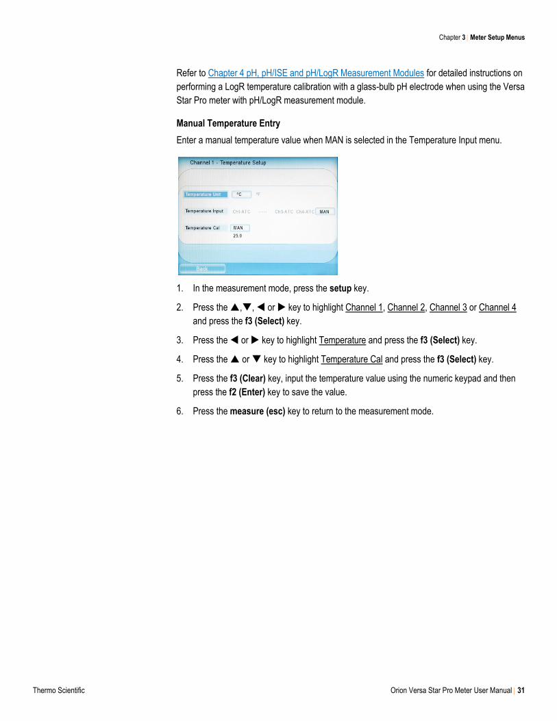
Manual Temperature Entry
Enter a manual temperature value when MAN is selected in the Temperature Input menu.
1. In the measurement mode, press the setup key.
2. Press the ,, or key to highlight Channel 1, Channel 2, Channel 3 or Channel 4
and press the f3 (Select) key.
3. Press the or key to highlight Temperature and press the f3 (Select) key.
4. Press the or key to highlight Temperature Cal and press the f3 (Select) key.
5. Press the f3 (Clear) key, input the temperature value using the numeric keypad and then
press the f2 (Enter) key to save the value.
6. Press the measure (esc) key to return to the measurement mode.
Chapter 3 Meter Setup Menus
32 Orion Versa Star Pro Meter User Manual Thermo Scientific
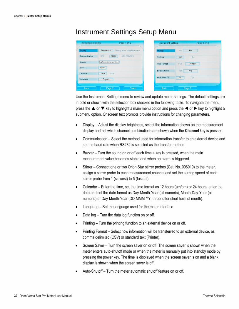
Instrument Settings Setup Menu
Use the Instrument Settings menu to review and update meter settings. The default settings are
in bold or shown with the selection box checked in the following table. To navigate the menu,
press the or key to highlight a main menu option and press the or key to highlight a
submenu option. Onscreen text prompts provide instructions for changing parameters.
Display – Adjust the display brightness, select the information shown on the measurement
display and set which channel combinations are shown when the Channel key is pressed.
Communication – Select the method used for information transfer to an external device and
set the baud rate when RS232 is selected as the transfer method.
Buzzer – Turn the sound on or off each time a key is pressed, when the main
measurement value becomes stable and when an alarm is triggered.
Stirrer – Connect one or two Orion Star stirrer probes (Cat. No. 096019) to the meter,
assign a stirrer probe to each measurement channel and set the stirring speed of each
stirrer probe from 1 (slowest) to 5 (fastest).
Calendar – Enter the time, set the time format as 12 hours (am/pm) or 24 hours, enter the
date and set the date format as Day-Month-Year (all numeric), Month-Day-Year (all
numeric) or Day-Month-Year (DD-MMM-YY, three letter short form of month).
Language – Set the language used for the meter interface.
Data log – Turn the data log function on or off.
Printing – Turn the printing function to an external device on or off.
Printing Format – Select how information will be transferred to an external device, as
comma delimited (CSV) or standard text (Printer).
Screen Saver – Turn the screen saver on or off. The screen saver is shown when the
meter enters auto-shutoff mode or when the meter is manually put into standby mode by
pressing the power key. The time is displayed when the screen saver is on and a blank
display is shown when the screen saver is off.
Auto-Shutoff – Turn the meter automatic shutoff feature on or off.
Chapter 3 Meter Setup Menus
Thermo Scientific Orion Versa Star Pro Meter User Manual 33
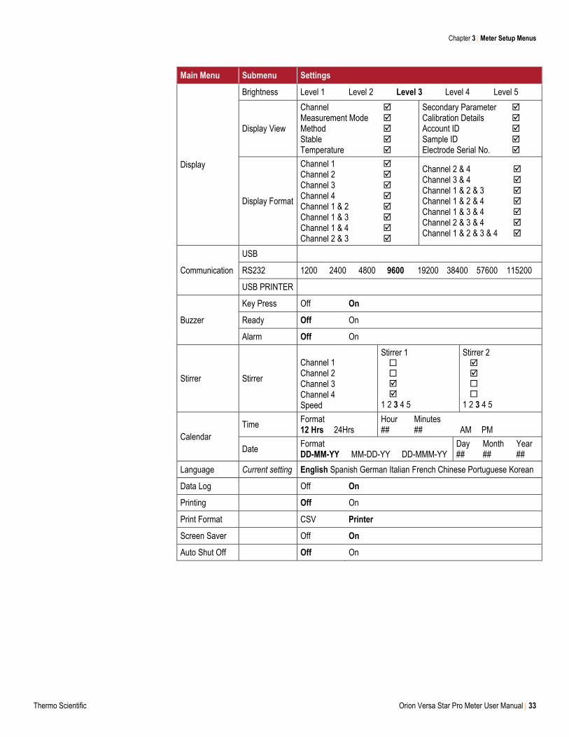
Main Menu Submenu Settings
Display
Brightness Level 1 Level 2 Level 3 Level 4 Level 5
Display View
Channel Measurement Mode Method Stable Temperature
Secondary Parameter Calibration Details Account ID Sample ID Electrode Serial No.
Display Format
Channel 1 Channel 2 Channel 3 Channel 4 Channel 1 & 2 Channel 1 & 3 Channel 1 & 4 Channel 2 & 3
Channel 2 & 4 Channel 3 & 4 Channel 1 & 2 & 3 Channel 1 & 2 & 4 Channel 1 & 3 & 4 Channel 2 & 3 & 4 Channel 1 & 2 & 3 & 4
Communication
USB
RS232 1200 2400 4800 9600 19200 38400 57600 115200
USB PRINTER
Buzzer
Key Press Off On
Ready Off On
Alarm Off On
Stirrer Stirrer
Channel 1 Channel 2 Channel 3 Channel 4 Speed
Stirrer 1 1 2 3 4 5
Stirrer 2 1 2 3 4 5
Calendar
Time Format 12 Hrs 24Hrs
Hour Minutes ## ## AM PM
Date Format DD-MM-YY MM-DD-YY DD-MMM-YY
Day Month Year ## ## ##
Language Current setting English Spanish German Italian French Chinese Portuguese Korean
Data Log Off On
Printing Off On
Print Format CSV Printer
Screen Saver Off On
Auto Shut Off Off On
Chapter 3 Meter Setup Menus
34 Orion Versa Star Pro Meter User Manual Thermo Scientific
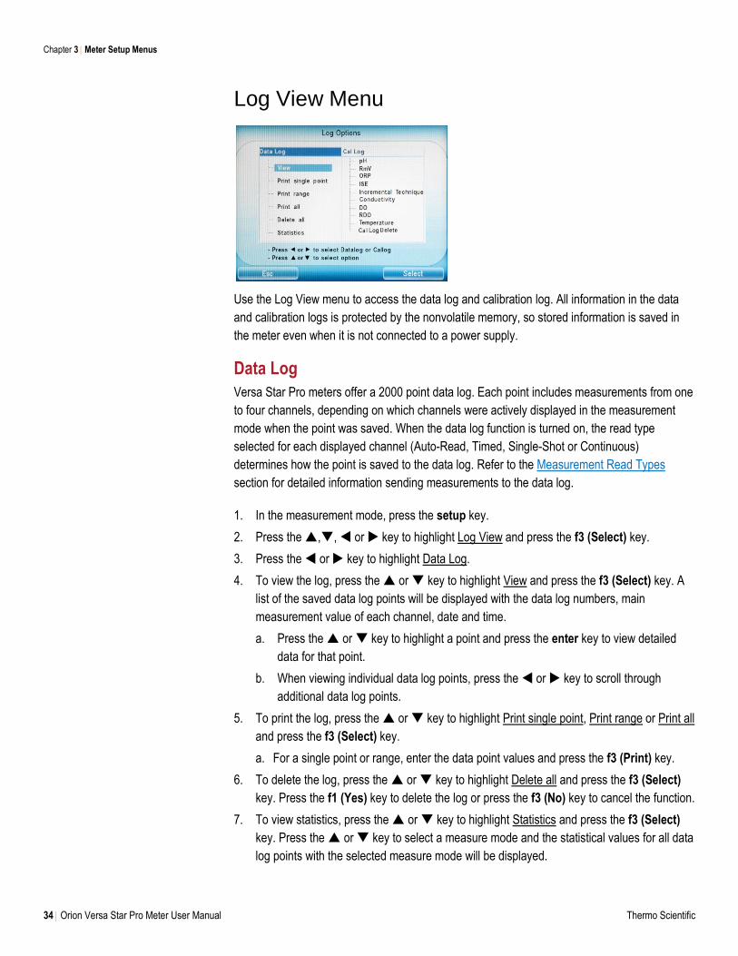
Log View Menu
Use the Log View menu to access the data log and calibration log. All information in the data
and calibration logs is protected by the nonvolatile memory, so stored information is saved in
the meter even when it is not connected to a power supply.
Data Log
Versa Star Pro meters offer a 2000 point data log. Each point includes measurements from one
to four channels, depending on which channels were actively displayed in the measurement
mode when the point was saved. When the data log function is turned on, the read type
selected for each displayed channel (Auto-Read, Timed, Single-Shot or Continuous)
determines how the point is saved to the data log. Refer to the Measurement Read Types
section for detailed information sending measurements to the data log.
1. In the measurement mode, press the setup key.
2. Press the ,, or key to highlight Log View and press the f3 (Select) key.
3. Press the or key to highlight Data Log.
4. To view the log, press the or key to highlight View and press the f3 (Select) key. A
list of the saved data log points will be displayed with the data log numbers, main
measurement value of each channel, date and time.
a. Press the or key to highlight a point and press the enter key to view detailed
data for that point.
b. When viewing individual data log points, press the or key to scroll through
additional data log points.
5. To print the log, press the or key to highlight Print single point, Print range or Print all
and press the f3 (Select) key.
a. For a single point or range, enter the data point values and press the f3 (Print) key.
6. To delete the log, press the or key to highlight Delete all and press the f3 (Select)
key. Press the f1 (Yes) key to delete the log or press the f3 (No) key to cancel the function.
7. To view statistics, press the or key to highlight Statistics and press the f3 (Select)
key. Press the or key to select a measure mode and the statistical values for all data
log points with the selected measure mode will be displayed.
Chapter 3 Meter Setup Menus
Thermo Scientific Orion Versa Star Pro Meter User Manual 35
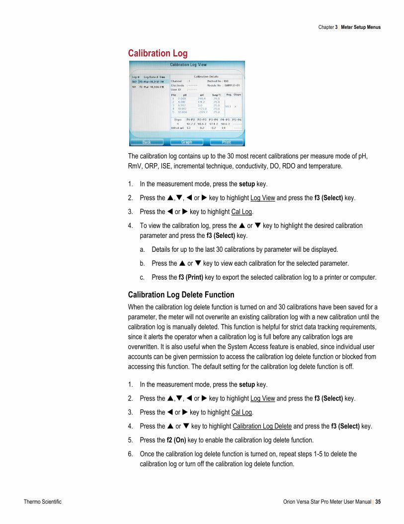
Calibration Log
The calibration log contains up to the 30 most recent calibrations per measure mode of pH,
RmV, ORP, ISE, incremental technique, conductivity, DO, RDO and temperature.
1. In the measurement mode, press the setup key.
2. Press the ,, or key to highlight Log View and press the f3 (Select) key.
3. Press the or key to highlight Cal Log.
4. To view the calibration log, press the or key to highlight the desired calibration
parameter and press the f3 (Select) key.
a. Details for up to the last 30 calibrations by parameter will be displayed.
b. Press the or key to view each calibration for the selected parameter.
c. Press the f3 (Print) key to export the selected calibration log to a printer or computer.
Calibration Log Delete Function
When the calibration log delete function is turned on and 30 calibrations have been saved for a
parameter, the meter will not overwrite an existing calibration log with a new calibration until the
calibration log is manually deleted. This function is helpful for strict data tracking requirements,
since it alerts the operator when a calibration log is full before any calibration logs are
overwritten. It is also useful when the System Access feature is enabled, since individual user
accounts can be given permission to access the calibration log delete function or blocked from
accessing this function. The default setting for the calibration log delete function is off.
1. In the measurement mode, press the setup key.
2. Press the ,, or key to highlight Log View and press the f3 (Select) key.
3. Press the or key to highlight Cal Log.
4. Press the or key to highlight Calibration Log Delete and press the f3 (Select) key.
5. Press the f2 (On) key to enable the calibration log delete function.
6. Once the calibration log delete function is turned on, repeat steps 1-5 to delete the
calibration log or turn off the calibration log delete function.
Chapter 3 Meter Setup Menus
36 Orion Versa Star Pro Meter User Manual Thermo Scientific
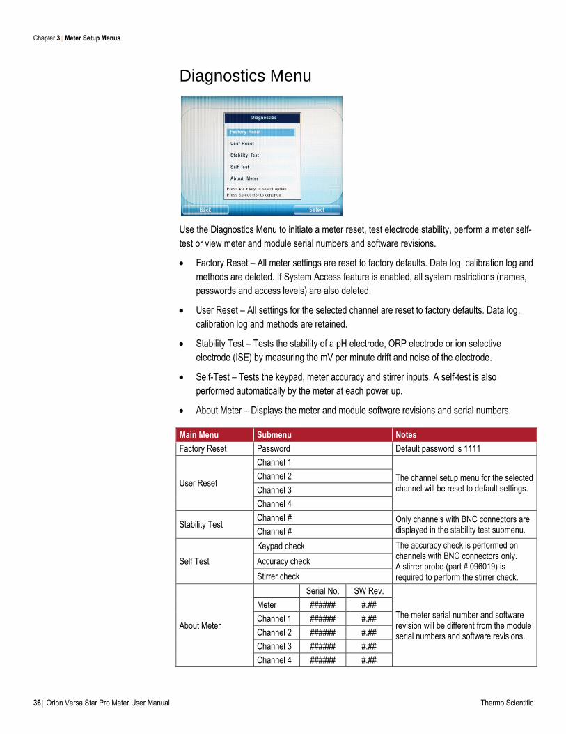
Diagnostics Menu
Use the Diagnostics Menu to initiate a meter reset, test electrode stability, perform a meter self-
test or view meter and module serial numbers and software revisions.
Factory Reset – All meter settings are reset to factory defaults. Data log, calibration log and
methods are deleted. If System Access feature is enabled, all system restrictions (names,
passwords and access levels) are also deleted.
User Reset – All settings for the selected channel are reset to factory defaults. Data log,
calibration log and methods are retained.
Stability Test – Tests the stability of a pH electrode, ORP electrode or ion selective
electrode (ISE) by measuring the mV per minute drift and noise of the electrode.
Self-Test – Tests the keypad, meter accuracy and stirrer inputs. A self-test is also
performed automatically by the meter at each power up.
About Meter – Displays the meter and module software revisions and serial numbers.
Main Menu Submenu Notes
Factory Reset Password Default password is 1111
User Reset
Channel 1
The channel setup menu for the selected channel will be reset to default settings.
Channel 2
Channel 3
Channel 4
Stability Test Channel # Only channels with BNC connectors are
displayed in the stability test submenu. Channel #
Self Test
Keypad check The accuracy check is performed on channels with BNC connectors only. A stirrer probe (part # 096019) is required to perform the stirrer check.
Accuracy check
Stirrer check
About Meter
Serial No. SW Rev.
The meter serial number and software revision will be different from the module serial numbers and software revisions.
Meter ###### #.##
Channel 1 ###### #.##
Channel 2 ###### #.##
Channel 3 ###### #.##
Channel 4 ###### #.##
Chapter 3 Meter Setup Menus
Thermo Scientific Orion Versa Star Pro Meter User Manual 37
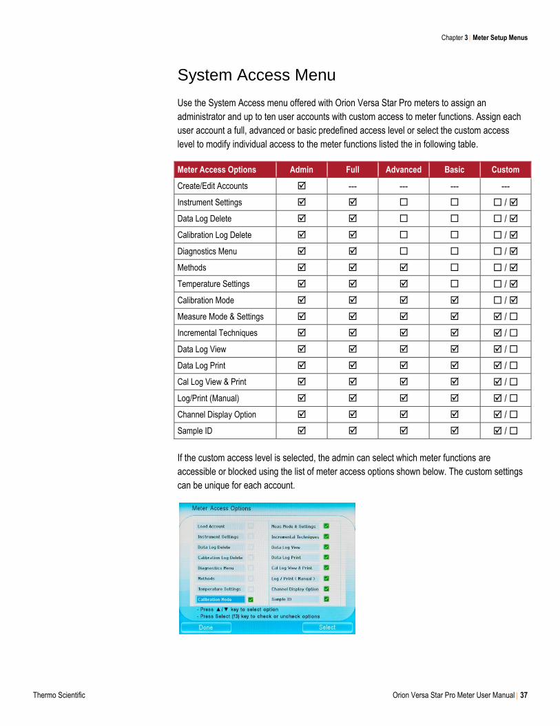
System Access Menu
Use the System Access menu offered with Orion Versa Star Pro meters to assign an
administrator and up to ten user accounts with custom access to meter functions. Assign each
user account a full, advanced or basic predefined access level or select the custom access
level to modify individual access to the meter functions listed the in following table.
Meter Access Options Admin Full Advanced Basic Custom
Create/Edit Accounts --- --- --- ---
Instrument Settings /
Data Log Delete /
Calibration Log Delete /
Diagnostics Menu /
Methods /
Temperature Settings /
Calibration Mode /
Measure Mode & Settings /
Incremental Techniques /
Data Log View /
Data Log Print /
Cal Log View & Print /
Log/Print (Manual) /
Channel Display Option /
Sample ID /
If the custom access level is selected, the admin can select which meter functions are
accessible or blocked using the list of meter access options shown below. The custom settings
can be unique for each account.
Chapter 3 Meter Setup Menus
38 Orion Versa Star Pro Meter User Manual Thermo Scientific
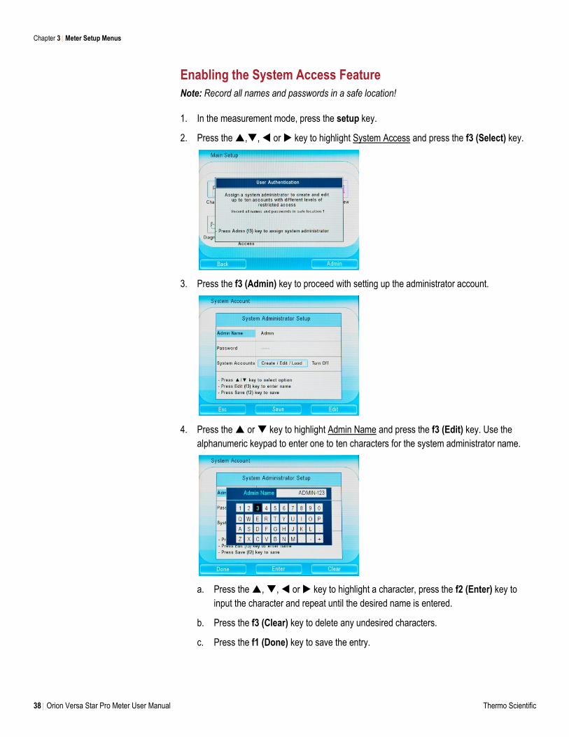
Enabling the System Access Feature
Note: Record all names and passwords in a safe location!
1. In the measurement mode, press the setup key.
2. Press the ,, or key to highlight System Access and press the f3 (Select) key.
3. Press the f3 (Admin) key to proceed with setting up the administrator account.
4. Press the or key to highlight Admin Name and press the f3 (Edit) key. Use the
alphanumeric keypad to enter one to ten characters for the system administrator name.
a. Press the , , or key to highlight a character, press the f2 (Enter) key to
input the character and repeat until the desired name is entered.
b. Press the f3 (Clear) key to delete any undesired characters.
c. Press the f1 (Done) key to save the entry.
Chapter 3 Meter Setup Menus
Thermo Scientific Orion Versa Star Pro Meter User Manual 39
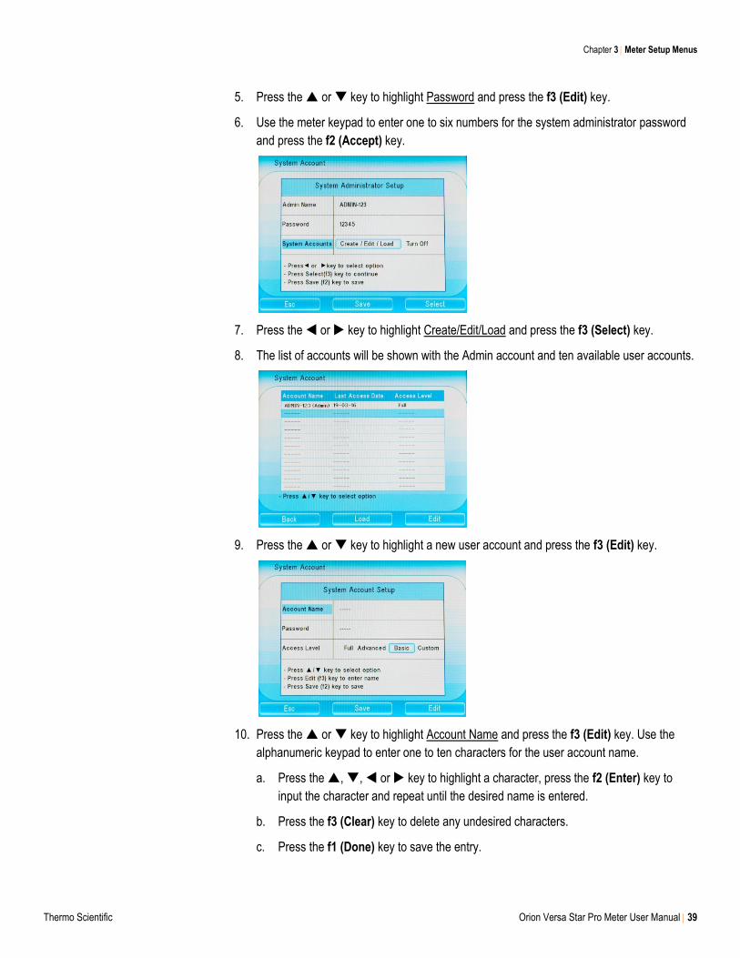
5. Press the or key to highlight Password and press the f3 (Edit) key.
6. Use the meter keypad to enter one to six numbers for the system administrator password
and press the f2 (Accept) key.
7. Press the or key to highlight Create/Edit/Load and press the f3 (Select) key.
8. The list of accounts will be shown with the Admin account and ten available user accounts.
9. Press the or key to highlight a new user account and press the f3 (Edit) key.
10. Press the or key to highlight Account Name and press the f3 (Edit) key. Use the
alphanumeric keypad to enter one to ten characters for the user account name.
a. Press the , , or key to highlight a character, press the f2 (Enter) key to
input the character and repeat until the desired name is entered.
b. Press the f3 (Clear) key to delete any undesired characters.
c. Press the f1 (Done) key to save the entry.
Chapter 3 Meter Setup Menus
40 Orion Versa Star Pro Meter User Manual Thermo Scientific
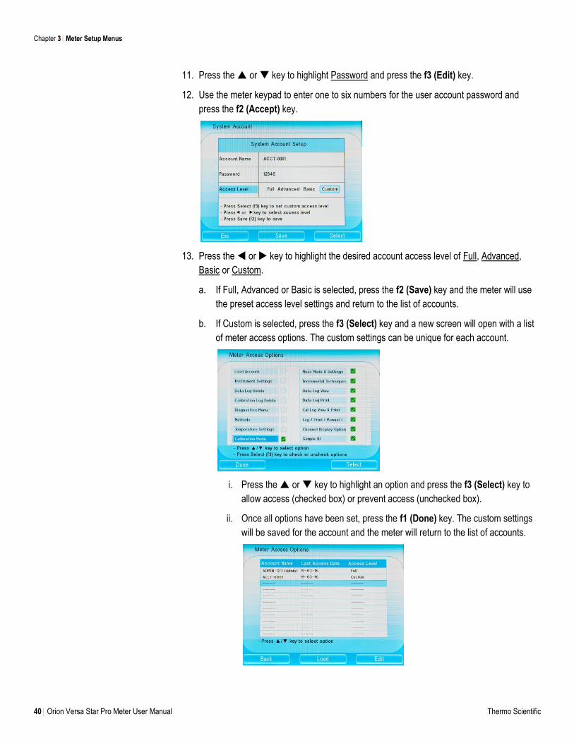
11. Press the or key to highlight Password and press the f3 (Edit) key.
12. Use the meter keypad to enter one to six numbers for the user account password and
press the f2 (Accept) key.
13. Press the or key to highlight the desired account access level of Full, Advanced,
Basic or Custom.
a. If Full, Advanced or Basic is selected, press the f2 (Save) key and the meter will use
the preset access level settings and return to the list of accounts.
b. If Custom is selected, press the f3 (Select) key and a new screen will open with a list
of meter access options. The custom settings can be unique for each account.
i. Press the or key to highlight an option and press the f3 (Select) key to
allow access (checked box) or prevent access (unchecked box).
ii. Once all options have been set, press the f1 (Done) key. The custom settings
will be saved for the account and the meter will return to the list of accounts.
Chapter 3 Meter Setup Menus
Thermo Scientific Orion Versa Star Pro Meter User Manual 41
14. Repeat steps 9-13 for all required user accounts.
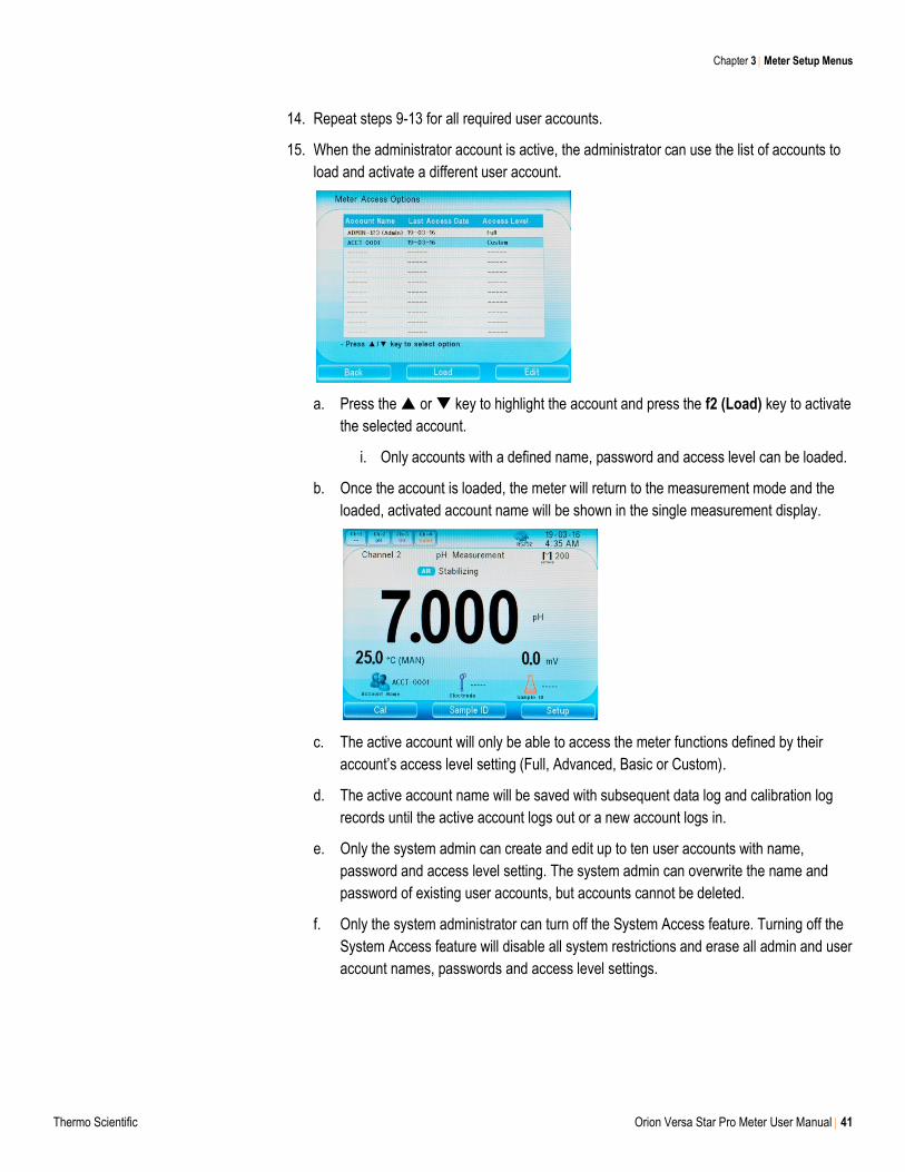
15. When the administrator account is active, the administrator can use the list of accounts to
load and activate a different user account.
a. Press the or key to highlight the account and press the f2 (Load) key to activate
the selected account.
i. Only accounts with a defined name, password and access level can be loaded.
b. Once the account is loaded, the meter will return to the measurement mode and the
loaded, activated account name will be shown in the single measurement display.
c. The active account will only be able to access the meter functions defined by their
account’s access level setting (Full, Advanced, Basic or Custom).
d. The active account name will be saved with subsequent data log and calibration log
records until the active account logs out or a new account logs in.
e. Only the system admin can create and edit up to ten user accounts with name,
password and access level setting. The system admin can overwrite the name and
password of existing user accounts, but accounts cannot be deleted.
f. Only the system administrator can turn off the System Access feature. Turning off the
System Access feature will disable all system restrictions and erase all admin and user
account names, passwords and access level settings.
Chapter 3 Meter Setup Menus
42 Orion Versa Star Pro Meter User Manual Thermo Scientific
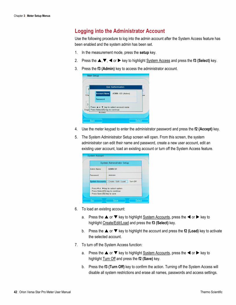
Logging into the Administrator Account
Use the following procedure to log into the admin account after the System Access feature has
been enabled and the system admin has been set.
1. In the measurement mode, press the setup key.
2. Press the ,, or key to highlight System Access and press the f3 (Select) key.
3. Press the f3 (Admin) key to access the administrator account.
4. Use the meter keypad to enter the administrator password and press the f2 (Accept) key.
5. The System Administrator Setup screen will open. From this screen, the system
administrator can edit their name and password, create a new user account, edit an
existing user account, load an existing account or turn off the System Access feature.
6. To load an existing account:
a. Press the or key to highlight System Accounts, press the or key to
highlight Create/Edit/Load and press the f3 (Select) key.
b. Press the or key to highlight the account and press the f2 (Load) key to activate
the selected account.
7. To turn off the System Access function:
a. Press the or key to highlight System Accounts, press the or key to
highlight Turn Off and press the f2 (Save) key.
b. Press the f3 (Turn Off) key to confirm the action. Turning off the System Access will
disable all system restrictions and erase all names, passwords and access settings.
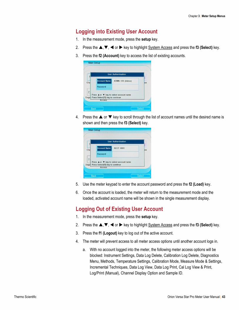
Chapter 3 Meter Setup Menus
Thermo Scientific Orion Versa Star Pro Meter User Manual 43
Logging into Existing User Account
1. In the measurement mode, press the setup key.
2. Press the ,, or key to highlight System Access and press the f3 (Select) key.
3. Press the f2 (Account) key to access the list of existing accounts.
4. Press the or key to scroll through the list of account names until the desired name is
shown and then press the f3 (Select) key.
5. Use the meter keypad to enter the account password and press the f2 (Load) key.
6. Once the account is loaded, the meter will return to the measurement mode and the
loaded, activated account name will be shown in the single measurement display.
Logging Out of Existing User Account
1. In the measurement mode, press the setup key.
2. Press the ,, or key to highlight System Access and press the f3 (Select) key.
3. Press the f1 (Logout) key to log out of the active account.
4. The meter will prevent access to all meter access options until another account logs in.
a. With no account logged into the meter, the following meter access options will be
blocked: Instrument Settings, Data Log Delete, Calibration Log Delete, Diagnostics
Menu, Methods, Temperature Settings, Calibration Mode, Measure Mode & Settings,
Incremental Techniques, Data Log View, Data Log Print, Cal Log View & Print,
Log/Print (Manual), Channel Display Option and Sample ID.
44 Orion Versa Star Pro Meter User Manual Thermo Scientific
4 pH, pH/ISE and pH/LogR Measurement Modules
Connecting Electrodes to the Module
To begin using the Versa Star Pro meter and module system, prepare the meter and insert the
module into an available channel on the back of the meter. See Chapter 2 Meter Basics for
instructions. For information on customizing meter settings, refer to Chapter 3 Setup Menu.
It is recommended that electrodes be placed in the meter-attached electrode stand for easy
movement in and out of beakers during calibration, sample measurement and storage.
Module Catalog # VSTAR-PH VSTAR-ISE VSTAR-LR
Label pH pH/ISE pH/LogR
Measure Modes pH, mV, RmV, ORP pH, mV, RmV, ORP, ISE pH, mV, RmV, ORP
Temperature Modes Automatic, Manual Automatic, Manual Automatic, Manual, LogR
Chapter 4
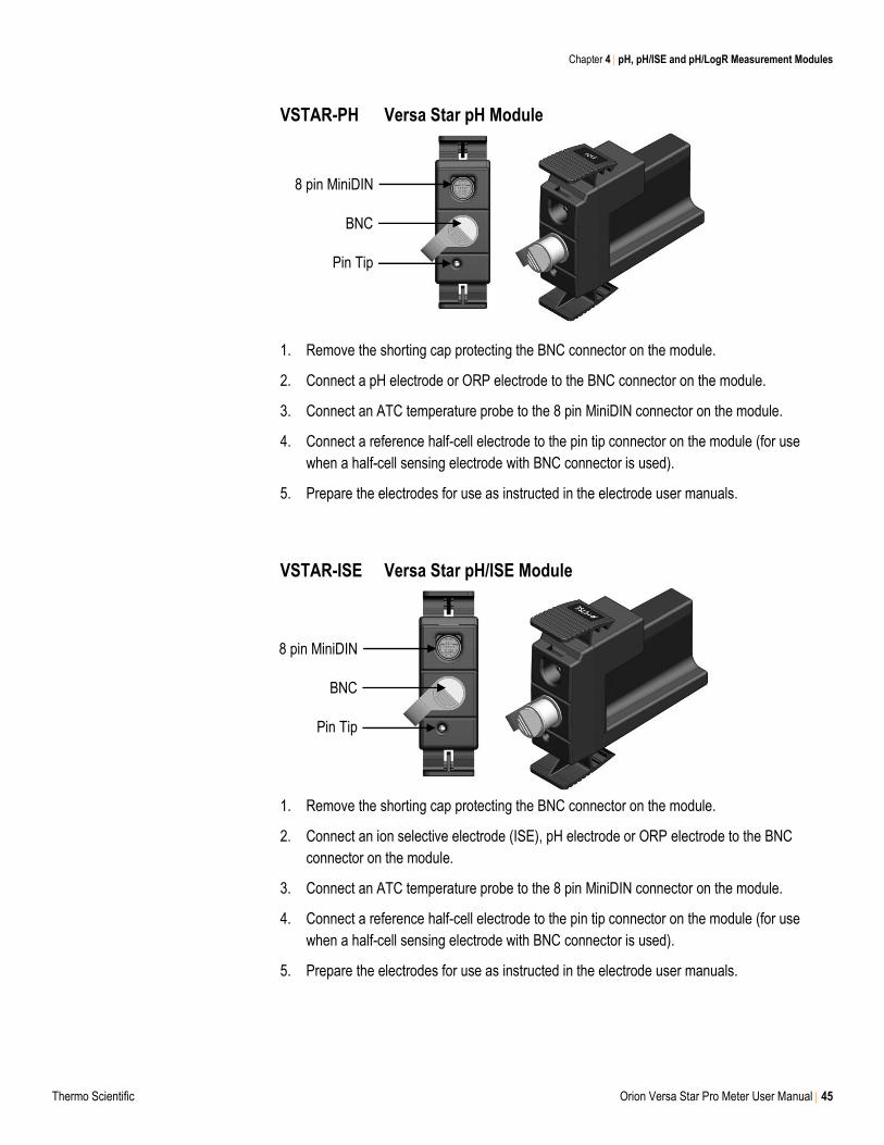
Chapter 4 pH, pH/ISE and pH/LogR Measurement Modules
Thermo Scientific Orion Versa Star Pro Meter User Manual 45
VSTAR-PH Versa Star pH Module
1. Remove the shorting cap protecting the BNC connector on the module.
2. Connect a pH electrode or ORP electrode to the BNC connector on the module.
3. Connect an ATC temperature probe to the 8 pin MiniDIN connector on the module.
4. Connect a reference half-cell electrode to the pin tip connector on the module (for use
when a half-cell sensing electrode with BNC connector is used).
5. Prepare the electrodes for use as instructed in the electrode user manuals.
VSTAR-ISE Versa Star pH/ISE Module
1. Remove the shorting cap protecting the BNC connector on the module.
2. Connect an ion selective electrode (ISE), pH electrode or ORP electrode to the BNC
connector on the module.
3. Connect an ATC temperature probe to the 8 pin MiniDIN connector on the module.
4. Connect a reference half-cell electrode to the pin tip connector on the module (for use
when a half-cell sensing electrode with BNC connector is used).
5. Prepare the electrodes for use as instructed in the electrode user manuals.
8 pin MiniDIN
BNC
Pin Tip
8 pin MiniDIN
BNC
Pin Tip
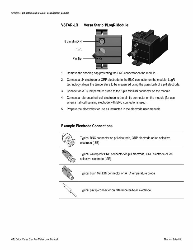
Chapter 4 pH, pH/ISE and pH/LogR Measurement Modules
46 Orion Versa Star Pro Meter User Manual Thermo Scientific
VSTAR-LR Versa Star pH/LogR Module
1. Remove the shorting cap protecting the BNC connector on the module.
2. Connect a pH electrode or ORP electrode to the BNC connector on the module. LogR
technology allows the temperature to be measured using the glass bulb of a pH electrode.
3. Connect an ATC temperature probe to the 8 pin MiniDIN connector on the module.
4. Connect a reference half-cell electrode to the pin tip connector on the module (for use
when a half-cell sensing electrode with BNC connector is used).
5. Prepare the electrodes for use as instructed in the electrode user manuals.
Example Electrode Connections
Typical BNC connector on pH electrode, ORP electrode or ion selective
electrode (ISE)
Typical waterproof BNC connector on pH electrode, ORP electrode or ion
selective electrode (ISE)
Typical 8 pin MiniDIN connector on ATC temperature probe
Typical pin tip connector on reference half-cell electrode
8 pin MiniDIN
BNC
Pin Tip
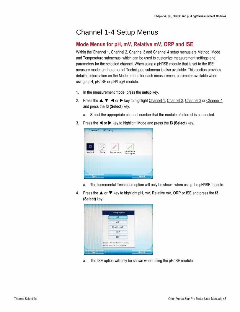
Chapter 4 pH, pH/ISE and pH/LogR Measurement Modules
Thermo Scientific Orion Versa Star Pro Meter User Manual 47
Channel 1-4 Setup Menus
Mode Menus for pH, mV, Relative mV, ORP and ISE
Within the Channel 1, Channel 2, Channel 3 and Channel 4 setup menus are Method, Mode
and Temperature submenus, which can be used to customize measurement settings and
parameters for the selected channel. When using a pH/ISE module that is set to the ISE
measure mode, an Incremental Techniques submenu is also available. This section provides
detailed information on the Mode menus for each measurement parameter available when
using a pH, pH/ISE or pH/LogR module.
1. In the measurement mode, press the setup key.
2. Press the ,, or key to highlight Channel 1, Channel 2, Channel 3 or Channel 4
and press the f3 (Select) key.
a. Select the appropriate channel number that the module of interest is connected.
3. Press the or key to highlight Mode and press the f3 (Select) key.
a. The Incremental Technique option will only be shown when using the pH/ISE module.
4. Press the or key to highlight pH, mV, Relative mV, ORP or ISE and press the f3
(Select) key.
a. The ISE option will only be shown when using the pH/ISE module.
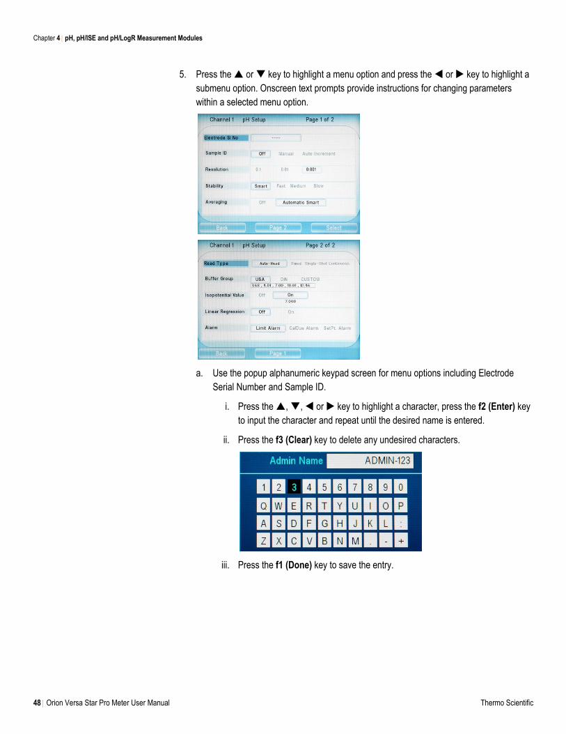
Chapter 4 pH, pH/ISE and pH/LogR Measurement Modules
48 Orion Versa Star Pro Meter User Manual Thermo Scientific
5. Press the or key to highlight a menu option and press the or key to highlight a
submenu option. Onscreen text prompts provide instructions for changing parameters
within a selected menu option.
a. Use the popup alphanumeric keypad screen for menu options including Electrode
Serial Number and Sample ID.
i. Press the , , or key to highlight a character, press the f2 (Enter) key
to input the character and repeat until the desired name is entered.
ii. Press the f3 (Clear) key to delete any undesired characters.
iii. Press the f1 (Done) key to save the entry.
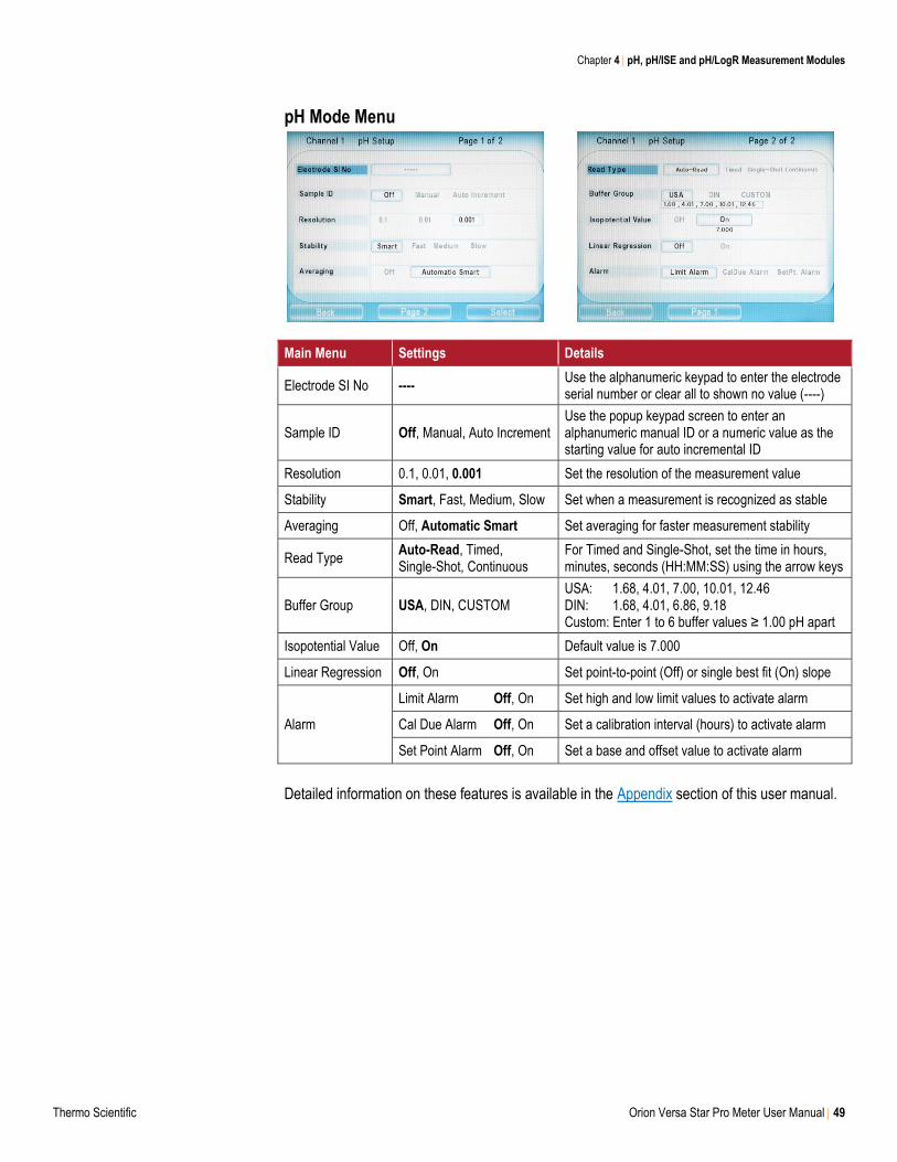
Chapter 4 pH, pH/ISE and pH/LogR Measurement Modules
Thermo Scientific Orion Versa Star Pro Meter User Manual 49
pH Mode Menu
Main Menu Settings Details
Electrode SI No ---- Use the alphanumeric keypad to enter the electrode serial number or clear all to shown no value (----)
Sample ID Off, Manual, Auto Increment Use the popup keypad screen to enter an alphanumeric manual ID or a numeric value as the starting value for auto incremental ID
Resolution 0.1, 0.01, 0.001 Set the resolution of the measurement value
Stability Smart, Fast, Medium, Slow Set when a measurement is recognized as stable
Averaging Off, Automatic Smart Set averaging for faster measurement stability
Read Type Auto-Read, Timed, Single-Shot, Continuous
For Timed and Single-Shot, set the time in hours, minutes, seconds (HH:MM:SS) using the arrow keys
Buffer Group USA, DIN, CUSTOM USA: 1.68, 4.01, 7.00, 10.01, 12.46 DIN: 1.68, 4.01, 6.86, 9.18 Custom: Enter 1 to 6 buffer values ≥ 1.00 pH apart
Isopotential Value Off, On Default value is 7.000
Linear Regression Off, On Set point-to-point (Off) or single best fit (On) slope
Alarm
Limit Alarm Off, On Set high and low limit values to activate alarm
Cal Due Alarm Off, On Set a calibration interval (hours) to activate alarm
Set Point Alarm Off, On Set a base and offset value to activate alarm
Detailed information on these features is available in the Appendix section of this user manual.
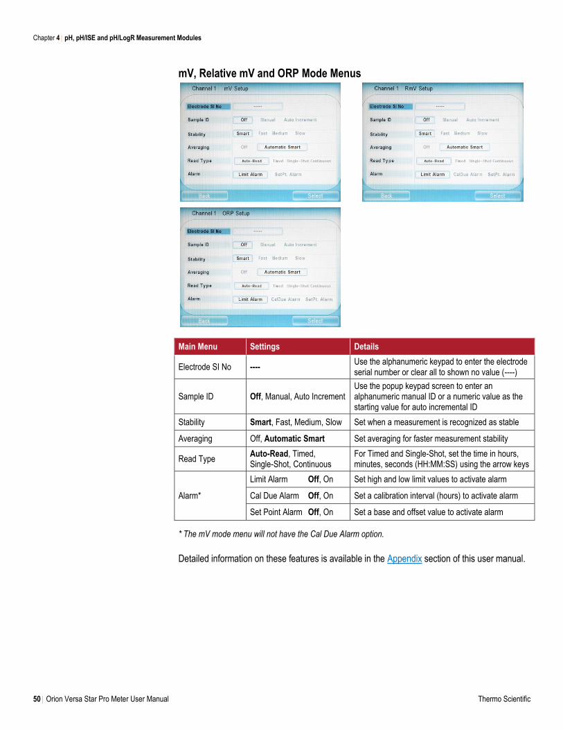
Chapter 4 pH, pH/ISE and pH/LogR Measurement Modules
50 Orion Versa Star Pro Meter User Manual Thermo Scientific
mV, Relative mV and ORP Mode Menus
Main Menu Settings Details
Electrode SI No ---- Use the alphanumeric keypad to enter the electrode serial number or clear all to shown no value (----)
Sample ID Off, Manual, Auto Increment Use the popup keypad screen to enter an alphanumeric manual ID or a numeric value as the starting value for auto incremental ID
Stability Smart, Fast, Medium, Slow Set when a measurement is recognized as stable
Averaging Off, Automatic Smart Set averaging for faster measurement stability
Read Type Auto-Read, Timed, Single-Shot, Continuous
For Timed and Single-Shot, set the time in hours, minutes, seconds (HH:MM:SS) using the arrow keys
Alarm*
Limit Alarm Off, On Set high and low limit values to activate alarm
Cal Due Alarm Off, On Set a calibration interval (hours) to activate alarm
Set Point Alarm Off, On Set a base and offset value to activate alarm
* The mV mode menu will not have the Cal Due Alarm option.
Detailed information on these features is available in the Appendix section of this user manual.
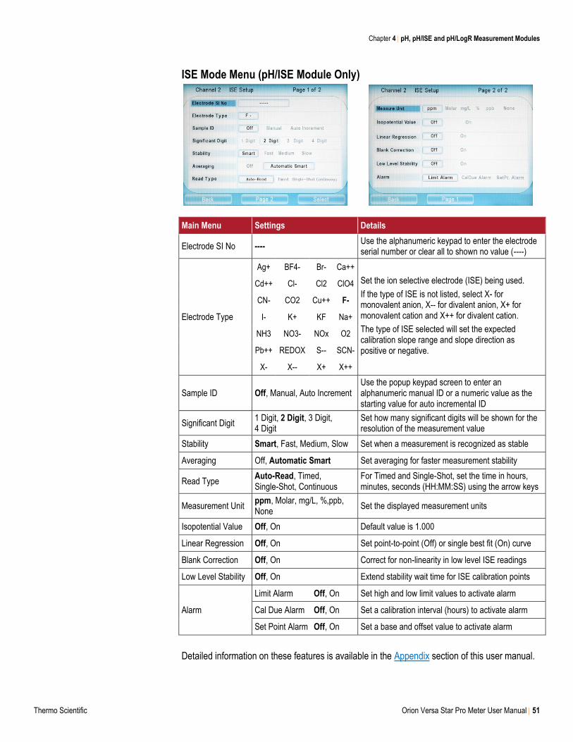
Chapter 4 pH, pH/ISE and pH/LogR Measurement Modules
Thermo Scientific Orion Versa Star Pro Meter User Manual 51
ISE Mode Menu (pH/ISE Module Only)
Main Menu Settings Details
Electrode SI No ---- Use the alphanumeric keypad to enter the electrode serial number or clear all to shown no value (----)
Electrode Type
Ag+ BF4- Br- Ca++
Set the ion selective electrode (ISE) being used.
If the type of ISE is not listed, select X- for monovalent anion, X-- for divalent anion, X+ for monovalent cation and X++ for divalent cation.
The type of ISE selected will set the expected calibration slope range and slope direction as positive or negative.
Cd++ Cl- Cl2 ClO4
CN- CO2 Cu++ F-
I- K+ KF Na+
NH3 NO3- NOx O2
Pb++ REDOX S-- SCN-
X- X-- X+ X++
Sample ID Off, Manual, Auto Increment Use the popup keypad screen to enter an alphanumeric manual ID or a numeric value as the starting value for auto incremental ID
Significant Digit 1 Digit, 2 Digit, 3 Digit, 4 Digit
Set how many significant digits will be shown for the resolution of the measurement value
Stability Smart, Fast, Medium, Slow Set when a measurement is recognized as stable
Averaging Off, Automatic Smart Set averaging for faster measurement stability
Read Type Auto-Read, Timed, Single-Shot, Continuous
For Timed and Single-Shot, set the time in hours, minutes, seconds (HH:MM:SS) using the arrow keys
Measurement Unit ppm, Molar, mg/L, %,ppb, None
Set the displayed measurement units
Isopotential Value Off, On Default value is 1.000
Linear Regression Off, On Set point-to-point (Off) or single best fit (On) curve
Blank Correction Off, On Correct for non-linearity in low level ISE readings
Low Level Stability Off, On Extend stability wait time for ISE calibration points
Alarm
Limit Alarm Off, On Set high and low limit values to activate alarm
Cal Due Alarm Off, On Set a calibration interval (hours) to activate alarm
Set Point Alarm Off, On Set a base and offset value to activate alarm
Detailed information on these features is available in the Appendix section of this user manual.
Chapter 4 pH, pH/ISE and pH/LogR Measurement Modules
52 Orion Versa Star Pro Meter User Manual Thermo Scientific
pH Calibration
One to six pH buffers can be used for calibration (up to six for a custom buffer group, up to five
for USA buffer group and up to four for DIN buffer group). Always use fresh pH buffers and
select buffers that bracket the sample pH and are one to four pH units apart.
Prepare the pH electrode according to the instructions in the electrode user manual. Connect
the pH electrode and any other electrodes to be used to the module inputs on the selected
channel. In the measurement mode, press the channel key until the channel with the pH,
pH/ISE or pH/LogR module with pH electrode connected is shown. If needed, press the mode
key until pH Measurement is shown as the measure mode.
1. Press the f1 (Cal) key to start the calibration.
a. If more than one channel is displayed in the measurement mode, press the or
key to highlight the desired channel and press the f3 (Select) key.
2. Rinse the pH electrode and any other electrodes in use with distilled water, blot dry with a
lint-free tissue and place into the pH buffer.
3. When the electrode and buffer are ready, press the f3 (Start) key.
a. If using a stirrer probe, the stirrer probe will start stirring when the f3 (Start) key is
pressed and stop stirring when the reading stabilizes.
4. Wait for the pH value on the meter to stabilize and perform one of the following actions:
a. Press the f2 (Accept) key to accept the displayed value.
or
b. Press the f3 (Edit) key and use the numeric keypad to enter the pH value. Press the
f2 (Accept) key to confirm the entered value.
5. Press the f2 (Next) key to proceed to the next buffer and repeat steps 2-4 or press the
f3 (Cal Done) key to save and end the calibration.
a. If a one point calibration is performed and the displayed slope needs to be edited,
press the f3 (Slope Edit) key and press the f3 (Clear) key, use the numeric keypad to
enter the new slope value and press the f2 (Accept) key.
6. The meter will display the calibration summary including the slope and export the data to
the calibration log. Press the measure (esc) key to proceed to the measurement mode.
pH Calibration Editing
Once the f3 (Cal Done) key is pressed and the calibration is saved, press the f2 (Cal Edit) key
to edit the calibration data and fix individual points without a full recalibration. In the calibration
edit mode, press the or key to highlight a calibration point and press the f2 (Delete) key
to delete the point or press the f3 (Re-Measure) key to re-measure the point. Follow the
onscreen text prompts and instructions to edit the selected calibration point.
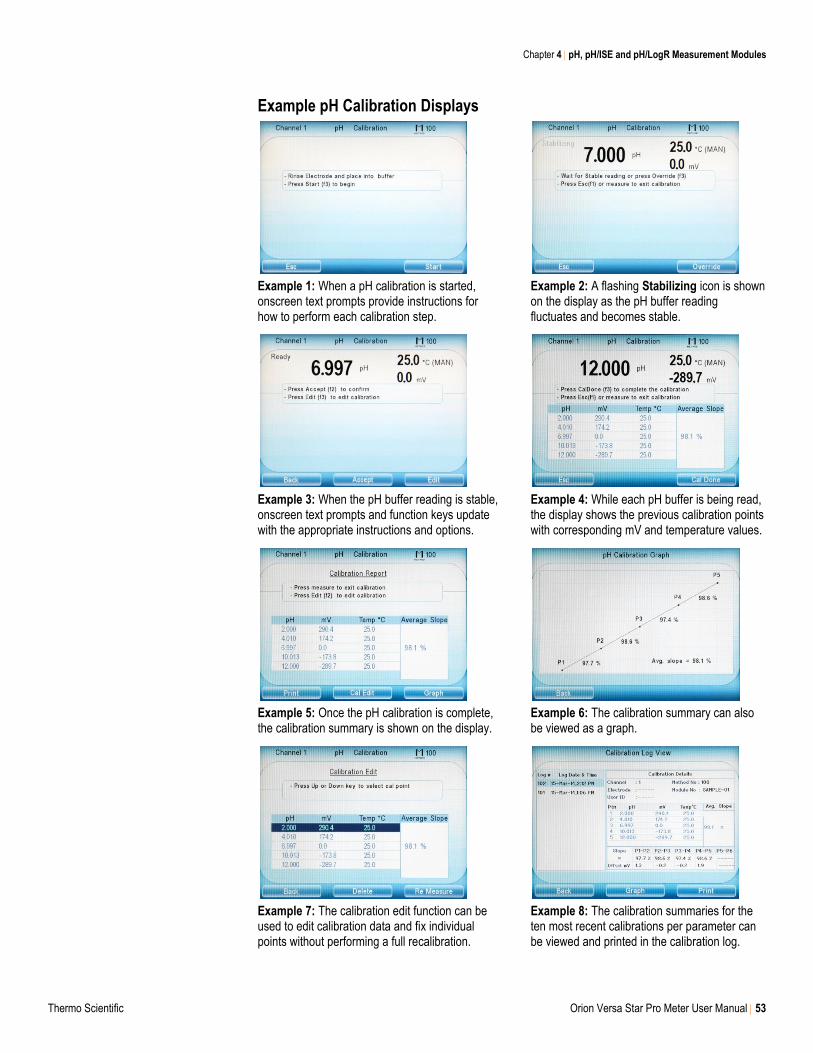
Chapter 4 pH, pH/ISE and pH/LogR Measurement Modules
Thermo Scientific Orion Versa Star Pro Meter User Manual 53
Example pH Calibration Displays
Example 1: When a pH calibration is started, onscreen text prompts provide instructions for how to perform each calibration step.
Example 2: A flashing Stabilizing icon is shown on the display as the pH buffer reading fluctuates and becomes stable.
Example 3: When the pH buffer reading is stable, onscreen text prompts and function keys update with the appropriate instructions and options.
Example 4: While each pH buffer is being read, the display shows the previous calibration points with corresponding mV and temperature values.
Example 5: Once the pH calibration is complete, the calibration summary is shown on the display.
Example 6: The calibration summary can also be viewed as a graph.
Example 7: The calibration edit function can be used to edit calibration data and fix individual points without performing a full recalibration.
Example 8: The calibration summaries for the ten most recent calibrations per parameter can be viewed and printed in the calibration log.
Chapter 4 pH, pH/ISE and pH/LogR Measurement Modules
54 Orion Versa Star Pro Meter User Manual Thermo Scientific
Relative mV Calibration
One standard can be used for relative mV calibration. Always use fresh standard for calibration.
Prepare the electrode according to the instructions in the electrode user manual. Connect the
electrode and any other electrodes to be used to the module inputs on the selected channel.
In the measurement mode, press the channel key until the channel with the pH, pH/ISE or
pH/LogR module with electrode connected is shown. If needed, press the mode key until RmV
Measurement is shown as the measure mode.
1. Press the f1 (Cal) key to start the calibration.
a. If more than one channel is displayed in the measurement mode, press the or
key to highlight the desired channel and press the f3 (Select) key.
2. Rinse the electrode and any other electrodes in use with distilled water, blot dry with a lint-
free tissue and place into the standard.
3. When the electrode and standard are ready, press the f3 (Start) key.
a. If using a stirrer probe, the stirrer probe will start stirring when the f3 (Start) key is
pressed and stop stirring when the reading stabilizes.
4. Wait for the mV value on the meter to stabilize and perform one of the following actions:
a. Press the f2 (Accept) key to accept the displayed value.
or
b. Press the f3 (Edit) key and use the f3 (Clear) key and numeric keypad to enter the
relative mV value. Press the f2 (Accept) key to confirm the entered value.
5. The meter will display the calibration summary including the mV offset. Press the
f3 (Cal Done) key to save the calibration and export the data to the calibration log. Press
the measure (esc) key to proceed to the measurement mode.

Chapter 4 pH, pH/ISE and pH/LogR Measurement Modules
Thermo Scientific Orion Versa Star Pro Meter User Manual 55
ORP Calibration
Versa Star Pro meters with pH, pH/ISE or pH/LogR modules offer a simple, automatic
calibration to the EH value (relative to the Standard Hydrogen Electrode, 420 mV at 25°C) in the
ORP mode when using the following items:
Thermo Scientific Orion ORP standard (Catalog Number 967901 or 967961)
Thermo Scientific Orion ORP electrode (Catalog Number 9678BNWP, 9778BNWP,
9180BNMD or 9179BNMD)
Thermo Scientific Orion 4 M KCl filling solution (Catalog Number 900011) or 4 M KCl gel
(in the 9179BNMD electrode)
Orion ORP standard is nonhazardous, stable and will not change over time, so it is an ideal
standard for any ORP measurement system. One ORP standard can be used for calibration.
Always use fresh ORP standard. Prepare the ORP electrode according to the instructions in the
electrode user manual. Connect the ORP electrode and any other electrodes to be used to the
module inputs on the selected channel.
In the measurement mode, press the channel key until the channel with the pH, pH/ISE or
pH/LogR module with ORP electrode connected is shown. If needed, press the mode key until
ORP Measurement is shown as the measure mode.
1. Press the f1 (Cal) key to start the calibration.
a. If more than one channel is displayed in the measurement mode, press the or
key to highlight the desired channel and press the f3 (Select) key.
2. Rinse the ORP electrode and any other electrodes in use with distilled water, blot dry with
a lint-free tissue and place into the standard.
3. When the electrode and standard are ready, press the f3 (Start) key.
a. If using a stirrer probe, the stirrer probe will start stirring when the f3 (Start) key is
pressed and stop stirring when the reading stabilizes.
4. Wait for the mV value on the meter to stabilize, indicated by the flashing stabilizing or
solid Ready icons. When the solid Ready icon appears, press the f2 (Accept) key to
confirm the ORP standard value.
5. The meter will display the calibration summary including the mV offset. Press the
f3 (Cal Done) key to save the calibration and then press the measure (esc) key to return
to measurement mode.
Chapter 4 pH, pH/ISE and pH/LogR Measurement Modules
56 Orion Versa Star Pro Meter User Manual Thermo Scientific
ISE Calibration (pH/ISE Module Only)
One to six standards can be used for ISE (ion selective electrode) calibration. If more than one
standard is used for calibration, start with the lowest concentration standard and work up to the
highest concentration standard last. Always use fresh standards. Select standards that bracket
the sample concentration and are one decade (10 times) apart in concentration. To accurately
prepare calibration standards from a stock solution, serial dilution is recommended using
calibrated pipettes. If ISA will be added to samples, the same ISA must be added to all
standards prior to calibration to ensure a consistent dilution factor.
Prepare the ISE according to the instructions in the electrode user manual. Connect the ISE
and any other electrodes to be used to the module inputs on the selected channel. In the
measurement mode, press the channel key until the channel with the pH/ISE module with ISE
connected is shown. If needed, press the mode key until ISE Measurement is shown as the
measure mode and use the ISE Mode Menu to set the Electrode Type.
1. Press the f1 (Cal) key to start the calibration.
a. If more than one channel is displayed in the measurement mode, press the or
key to highlight the desired channel and press the f3 (Select) key.
2. Rinse the ISE and any other electrodes in use with distilled water or rinse solution required
for that electrode. Blot the electrode dry with a lint-free tissue or shake the electrode and
then place into the standard. Do not wipe or rub the sensing element of the electrode.
Follow all electrode rinsing and drying instructions or exceptions in the ISE user manual.
3. When the electrode and standard are ready, press the f3 (Start) key.
a. If using a stirrer probe, the stirrer probe will start stirring when the f3 (Start) key is
pressed and stop stirring when the reading stabilizes.
4. Wait for the concentration value to stabilize and perform one of the following actions:
a. Press the f2 (Accept) key to accept the displayed value.
or
b. Press the f3 (Edit) key and use the numeric keypad to enter the concentration value.
Press the f2 (Accept) key to confirm the entered value.
5. Press the f2 (Next) key to proceed to the next standard and repeat steps 2-4 or press the
f3 (Cal Done) key to save and end the calibration.
6. The meter will display the calibration summary including the slope and export the data to
the calibration log. Press the measure (esc) key to proceed to the measurement mode.
ISE Calibration Editing
Once the f3 (Cal Done) key is pressed and the calibration is saved, press the f2 (Cal Edit) key
to edit the calibration data and fix individual points without a full recalibration. In the calibration
edit mode, press the or key to highlight a calibration point and press the f2 (Delete) key
to delete the point or press the f3 (Re-Measure) key to re-measure the point. Follow the
onscreen text prompts and instructions to edit the selected calibration point.
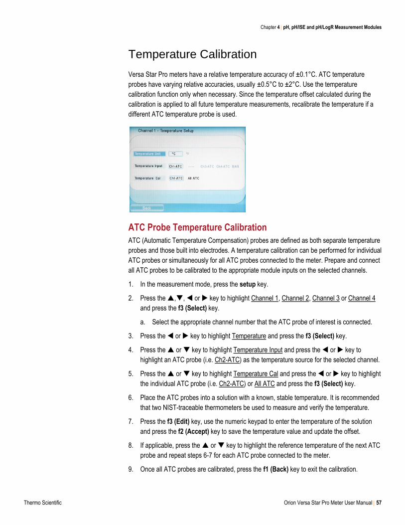
Chapter 4 pH, pH/ISE and pH/LogR Measurement Modules
Thermo Scientific Orion Versa Star Pro Meter User Manual 57
Temperature Calibration
Versa Star Pro meters have a relative temperature accuracy of ±0.1°C. ATC temperature
probes have varying relative accuracies, usually ±0.5°C to ±2°C. Use the temperature
calibration function only when necessary. Since the temperature offset calculated during the
calibration is applied to all future temperature measurements, recalibrate the temperature if a
different ATC temperature probe is used.
ATC Probe Temperature Calibration
ATC (Automatic Temperature Compensation) probes are defined as both separate temperature
probes and those built into electrodes. A temperature calibration can be performed for individual
ATC probes or simultaneously for all ATC probes connected to the meter. Prepare and connect
all ATC probes to be calibrated to the appropriate module inputs on the selected channels.
1. In the measurement mode, press the setup key.
2. Press the ,, or key to highlight Channel 1, Channel 2, Channel 3 or Channel 4
and press the f3 (Select) key.
a. Select the appropriate channel number that the ATC probe of interest is connected.
3. Press the or key to highlight Temperature and press the f3 (Select) key.
4. Press the or key to highlight Temperature Input and press the or key to
highlight an ATC probe (i.e. Ch2-ATC) as the temperature source for the selected channel.
5. Press the or key to highlight Temperature Cal and press the or key to highlight
the individual ATC probe (i.e. Ch2-ATC) or All ATC and press the f3 (Select) key.
6. Place the ATC probes into a solution with a known, stable temperature. It is recommended
that two NIST-traceable thermometers be used to measure and verify the temperature.
7. Press the f3 (Edit) key, use the numeric keypad to enter the temperature of the solution
and press the f2 (Accept) key to save the temperature value and update the offset.
8. If applicable, press the or key to highlight the reference temperature of the next ATC
probe and repeat steps 6-7 for each ATC probe connected to the meter.
9. Once all ATC probes are calibrated, press the f1 (Back) key to exit the calibration.
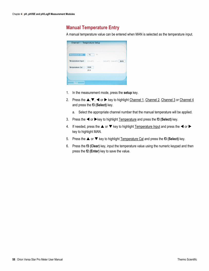
Chapter 4 pH, pH/ISE and pH/LogR Measurement Modules
58 Orion Versa Star Pro Meter User Manual Thermo Scientific
Manual Temperature Entry
A manual temperature value can be entered when MAN is selected as the temperature input.
1. In the measurement mode, press the setup key.
2. Press the ,, or key to highlight Channel 1, Channel 2, Channel 3 or Channel 4
and press the f3 (Select) key.
a. Select the appropriate channel number that the manual temperature will be applied.
3. Press the or key to highlight Temperature and press the f3 (Select) key.
4. If needed, press the or key to highlight Temperature Input and press the or
key to highlight MAN.
5. Press the or key to highlight Temperature Cal and press the f3 (Select) key.
6. Press the f3 (Clear) key, input the temperature value using the numeric keypad and then
press the f2 (Enter) key to save the value.
Chapter 4 pH, pH/ISE and pH/LogR Measurement Modules
Thermo Scientific Orion Versa Star Pro Meter User Manual 59
LogR Temperature Calibration (pH/LogR Module Only)
The Versa Star Pro meter with pH/LogR measurement module offers the option for temperature
calibration of a pH electrode, allowing most standard glass-bulb pH electrodes to be used for
automatic temperature compensation. The type and quality of pH electrode used to perform
LogR temperature measurements will contribute to the overall temperature accuracy of the
system. To maximize LogR performance and accuracy, a Thermo Scientific™ Orion™ ROSS
Ultra™ or Thermo Scientific™ Orion™ ROSS™ pH electrode is recommended.
LogR technology is based on using the electrical resistance of a pH electrode’s pH-sensing
glass-bulb as the temperature source. The logarithm of the resistance of the bulb varies almost
linearly with the reciprocal of the absolute temperature. Almost all standard glass-bulb pH
electrodes exhibit a similar decrease in resistance with increasing temperature.
LogR Temperature Calibration Recommendations
When using the meter for the first time or restarting the meter in the LogR temperature
mode, a LogR temperature calibration must be performed. A LogR temperature calibration
should be performed at least once per week to ensure accurate temperature compensation
when using the LogR temperature mode. Recalibrate the LogR temperature if the meter is
disconnected from the power supply or the pH electrode is disconnected from the meter.
Up to a three point LogR temperature calibration can be performed. It is recommended that
at least two calibration points be used to meet optimum system accuracy.
Choose a temperature calibration range that is 5°C to 20°C apart, depending on the
expected sample temperature range, and evenly bracket the expected temperature range.
For example, if sample temperatures are around 25°C, calibrate at 15°C and 35°C. For
sample temperatures that differ by more than 20°C, a three point LogR temperature
calibration is recommended. For many samples, a one point LogR calibration near the
expected sample temperature will yield adequate results.
A constant temperature bath or a hot plate is recommended to hold the temperature of the
calibrating solution.
For best results during temperature calibration, it is recommended that a pH buffer or tap
water be used as the temperature calibrating solution. Do not use distilled water because
the conductivity is too low to obtain a good temperature calibration.
LogR temperature calibration can be performed using a NIST-traceable thermometer or
ATC probe. The most accurate method is to use a NIST-traceable thermometer. It is
recommended that two NIST-traceable thermometers be used to measure and verify the
temperature value. The fastest method is to use an ATC probe. If an ATC probe is
connected with the pH/LogR module when a LogR temperature calibration is performed,
the meter will import the temperature value from the ATC probe as the reference
temperature during the calibration. The temperature source used to perform the LogR
temperature calibration will contribute to the overall temperature accuracy of the system.
Detailed information on this feature is available in the Appendix section of this user manual.
Chapter 4 pH, pH/ISE and pH/LogR Measurement Modules
60 Orion Versa Star Pro Meter User Manual Thermo Scientific
LogR Temperature Calibration Procedure
Prepare the glass-bulb pH electrode according to the instructions in the electrode user manual.
Connect the pH electrode to the pH/LogR module input on the selected channel. If an ATC
probe will be used as the temperature source, prepare and connect the ATC probe to the
pH/LogR module input on the same channel. Use a constant temperature bath or a hot plate to
attain the desired temperatures of the calibration solutions.
1. In the measurement mode, press the setup key.
2. Press the ,, or key to highlight Channel 1, Channel 2, Channel 3 or Channel 4
and press the f3 (Select) key.
a. Select the appropriate channel number that the pH/LogR module is connected.
3. Press the or key to highlight Temperature and press the f3 (Select) key.
4. Press the or key to highlight Temperature Input and press the or key to
highlight the pH electrode that will be used for the LogR mode (i.e. Ch2-LogR).
This enables the LogR mode for the selected channel and allows a LogR temperature
calibration to be performed.
5. Press the or key to highlight Temperature Cal and press the f3 (Select) key.
6. Place the pH electrode and NIST-traceable thermometers or ATC probe into a calibration
solution (pH buffer or tap water) with a known, stable temperature. Moderately stir the
solution using an Orion Star stirrer probe (Catalog Number 096019) or stir plate with stir bar.
7. Press the f3 (Start) key and wait for the temperature value on the meter to stabilize.
a. If using a stirrer probe, the stirrer probe will start stirring when the f3 (Start) key is
pressed and stop stirring when the reading stabilizes.
8. Once the temperature value is stable, perform one of the following actions:
a. Press the f2 (Accept) key to accept the displayed value.
or
b. Press the f3 (Edit) key, press the f3 (Clear) key, use the numeric keypad to enter the
temperature value and press the f2 (Accept) key to confirm the entered value.
9. Press the f2 (Next) key to proceed to the next calibration point and repeat steps 6-8 or
press the f3 (Cal Done) key to save and end the calibration.
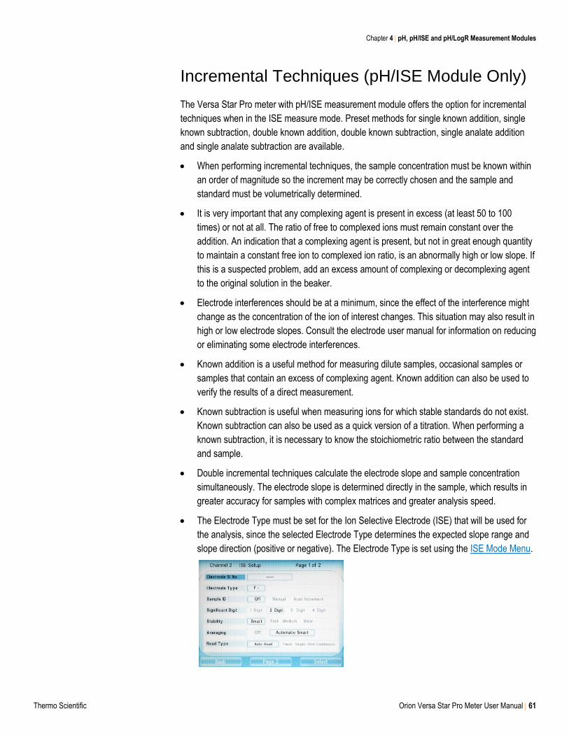
Chapter 4 pH, pH/ISE and pH/LogR Measurement Modules
Thermo Scientific Orion Versa Star Pro Meter User Manual 61
Incremental Techniques (pH/ISE Module Only)
The Versa Star Pro meter with pH/ISE measurement module offers the option for incremental
techniques when in the ISE measure mode. Preset methods for single known addition, single
known subtraction, double known addition, double known subtraction, single analate addition
and single analate subtraction are available.
When performing incremental techniques, the sample concentration must be known within
an order of magnitude so the increment may be correctly chosen and the sample and
standard must be volumetrically determined.
It is very important that any complexing agent is present in excess (at least 50 to 100
times) or not at all. The ratio of free to complexed ions must remain constant over the
addition. An indication that a complexing agent is present, but not in great enough quantity
to maintain a constant free ion to complexed ion ratio, is an abnormally high or low slope. If
this is a suspected problem, add an excess amount of complexing or decomplexing agent
to the original solution in the beaker.
Electrode interferences should be at a minimum, since the effect of the interference might
change as the concentration of the ion of interest changes. This situation may also result in
high or low electrode slopes. Consult the electrode user manual for information on reducing
or eliminating some electrode interferences.
Known addition is a useful method for measuring dilute samples, occasional samples or
samples that contain an excess of complexing agent. Known addition can also be used to
verify the results of a direct measurement.
Known subtraction is useful when measuring ions for which stable standards do not exist.
Known subtraction can also be used as a quick version of a titration. When performing a
known subtraction, it is necessary to know the stoichiometric ratio between the standard
and sample.
Double incremental techniques calculate the electrode slope and sample concentration
simultaneously. The electrode slope is determined directly in the sample, which results in
greater accuracy for samples with complex matrices and greater analysis speed.
The Electrode Type must be set for the Ion Selective Electrode (ISE) that will be used for
the analysis, since the selected Electrode Type determines the expected slope range and
slope direction (positive or negative). The Electrode Type is set using the ISE Mode Menu.
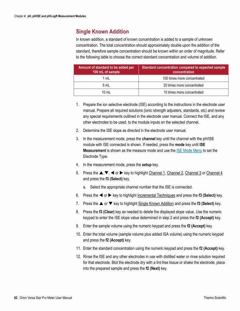
Chapter 4 pH, pH/ISE and pH/LogR Measurement Modules
62 Orion Versa Star Pro Meter User Manual Thermo Scientific
Single Known Addition
In known addition, a standard of known concentration is added to a sample of unknown
concentration. The total concentration should approximately double upon the addition of the
standard, therefore sample concentration should be known within an order of magnitude. Refer
to the following table to choose the correct standard concentration and volume of addition.
Amount of standard to be added per 100 mL of sample
Standard concentration compared to expected sample concentration
1 mL 100 times more concentrated
5 mL 20 times more concentrated
10 mL 10 times more concentrated
1. Prepare the ion selective electrode (ISE) according to the instructions in the electrode user
manual. Prepare all required solutions (ionic strength adjusters, standards, etc) and review
any special requirements outlined in the electrode user manual. Connect the ISE, and any
other electrodes to be used, to the module inputs on the selected channel.
2. Determine the ISE slope as directed in the electrode user manual.
3. In the measurement mode, press the channel key until the channel with the pH/ISE
module with ISE connected is shown. If needed, press the mode key until ISE
Measurement is shown as the measure mode and use the ISE Mode Menu to set the
Electrode Type.
4. In the measurement mode, press the setup key.
5. Press the ,, or key to highlight Channel 1, Channel 2, Channel 3 or Channel 4
and press the f3 (Select) key.
a. Select the appropriate channel number that the ISE is connected.
6. Press the or key to highlight Incremental Techniques and press the f3 (Select) key.
7. Press the or key to highlight Single Known Addition and press the f3 (Select) key.
8. Press the f3 (Clear) key as needed to delete the displayed slope value. Use the numeric
keypad to enter the ISE slope value determined in step 2 and press the f2 (Accept) key.
9. Enter the sample volume using the numeric keypad and press the f2 (Accept) key.
10. Enter the total volume (sample volume plus added ISA volume) using the numeric keypad
and press the f2 (Accept) key.
11. Enter the standard concentration using the numeric keypad and press the f2 (Accept) key.
12. Rinse the ISE and any other electrodes in use with distilled water or rinse solution required
for that electrode. Blot the electrode dry with a lint-free tissue or shake the electrode, place
into the prepared sample and press the f2 (Next) key.
Chapter 4 pH, pH/ISE and pH/LogR Measurement Modules
Thermo Scientific Orion Versa Star Pro Meter User Manual 63
a. Follow all electrode rinsing and drying instructions or exceptions in the ISE user
manual. Do not wipe or rub the sensing element of the electrode.
13. Wait for the mV value on the meter to stabilize and press the f2 (Accept) key.
14. Enter the standard volume using the numeric keypad and press the f2 (Accept) key.
15. Add the standard to the sample and press the f2 (Yes) key.
16. Wait for the mV value on the meter to stabilize and press the f2 (Accept) key.
17. The meter will display the calculated sample concentration and summary of the incremental
technique performed. Press the f1 (Esc) key to proceed to the measurement mode or press
the f2 (Next) key to perform another analysis.
Saving the Incremental Technique as a Method
For frequently used incremental techniques, Versa Star Pro meters now allow individual
incremental techniques to be stored as methods.
1. In the measurement mode, press the setup key.
2. Press the ,, or key to highlight Channel 1, Channel 2, Channel 3 or Channel 4
and press the f3 (Select) key.
3. Press the or key to highlight Method and press the f3 (Select) key.
4. Press the or key to highlight Edit / Create and press the f3 (Select) key.
5. Press the or key to highlight a new method and press the f3 (Edit) key.
6. Press the or key to highlight Inc. Tech and press the f3 (Select) key.
7. Press the or key to highlight Single Known Addition and press the f3 (Select) key.
8. Press the or key to highlight a value and press the f3 (Edit) key. Use the meter’s
numeric keypad to enter the value and press the f2 (Accept) key. Repeat for all values.
9. Once all the values for Single Known Addition have been entered, press the f2 (Save) key.
10. The meter will display the ISE measure mode setup menu. Review and update the
measurement parameters for the method and then press the f1 (Back) key.
11. Press the or key to highlight Load from the main method menu and press the f3
(Select) key.
12. Press the or key to highlight the ISE method for Single Known Addition and press
the f3 (Load) key. The meter will return to the measurement mode with the method loaded.
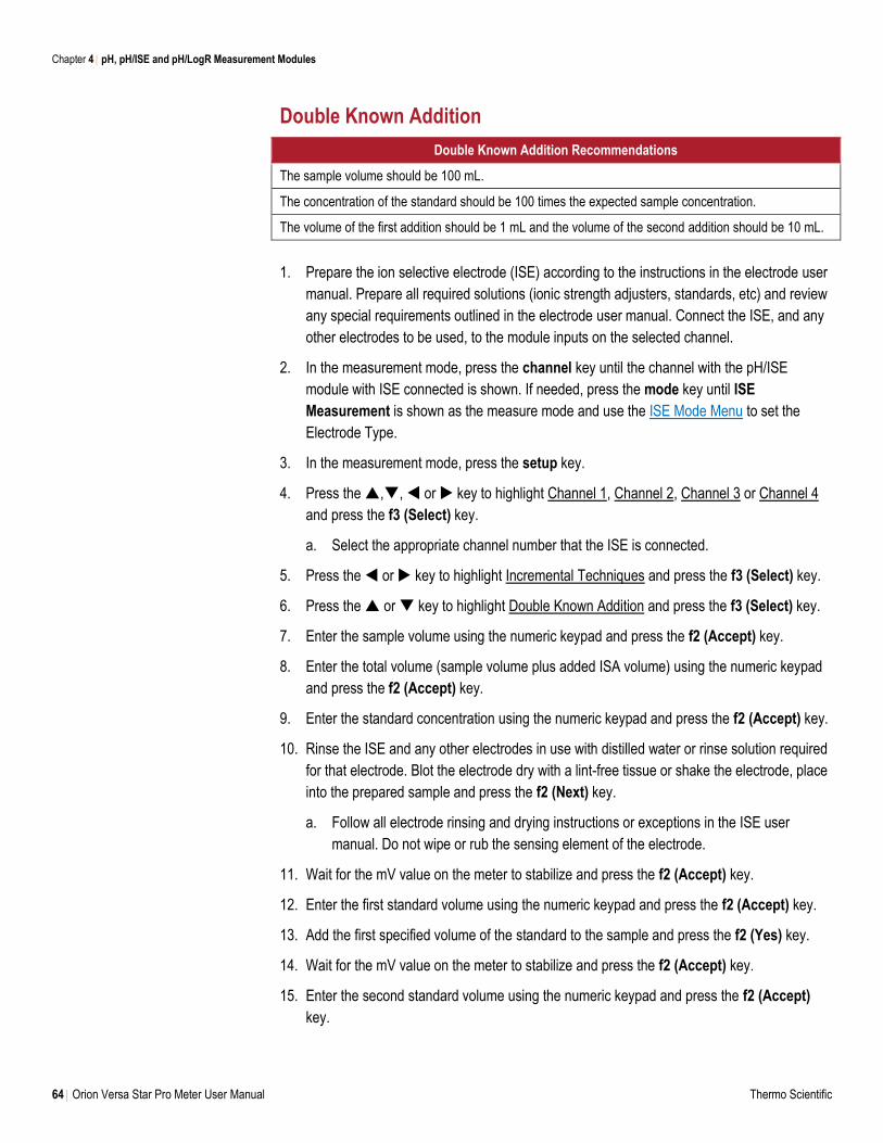
Chapter 4 pH, pH/ISE and pH/LogR Measurement Modules
64 Orion Versa Star Pro Meter User Manual Thermo Scientific
Double Known Addition
Double Known Addition Recommendations
The sample volume should be 100 mL.
The concentration of the standard should be 100 times the expected sample concentration.
The volume of the first addition should be 1 mL and the volume of the second addition should be 10 mL.
1. Prepare the ion selective electrode (ISE) according to the instructions in the electrode user
manual. Prepare all required solutions (ionic strength adjusters, standards, etc) and review
any special requirements outlined in the electrode user manual. Connect the ISE, and any
other electrodes to be used, to the module inputs on the selected channel.
2. In the measurement mode, press the channel key until the channel with the pH/ISE
module with ISE connected is shown. If needed, press the mode key until ISE
Measurement is shown as the measure mode and use the ISE Mode Menu to set the
Electrode Type.
3. In the measurement mode, press the setup key.
4. Press the ,, or key to highlight Channel 1, Channel 2, Channel 3 or Channel 4
and press the f3 (Select) key.
a. Select the appropriate channel number that the ISE is connected.
5. Press the or key to highlight Incremental Techniques and press the f3 (Select) key.
6. Press the or key to highlight Double Known Addition and press the f3 (Select) key.
7. Enter the sample volume using the numeric keypad and press the f2 (Accept) key.
8. Enter the total volume (sample volume plus added ISA volume) using the numeric keypad
and press the f2 (Accept) key.
9. Enter the standard concentration using the numeric keypad and press the f2 (Accept) key.
10. Rinse the ISE and any other electrodes in use with distilled water or rinse solution required
for that electrode. Blot the electrode dry with a lint-free tissue or shake the electrode, place
into the prepared sample and press the f2 (Next) key.
a. Follow all electrode rinsing and drying instructions or exceptions in the ISE user
manual. Do not wipe or rub the sensing element of the electrode.
11. Wait for the mV value on the meter to stabilize and press the f2 (Accept) key.
12. Enter the first standard volume using the numeric keypad and press the f2 (Accept) key.
13. Add the first specified volume of the standard to the sample and press the f2 (Yes) key.
14. Wait for the mV value on the meter to stabilize and press the f2 (Accept) key.
15. Enter the second standard volume using the numeric keypad and press the f2 (Accept)
key.
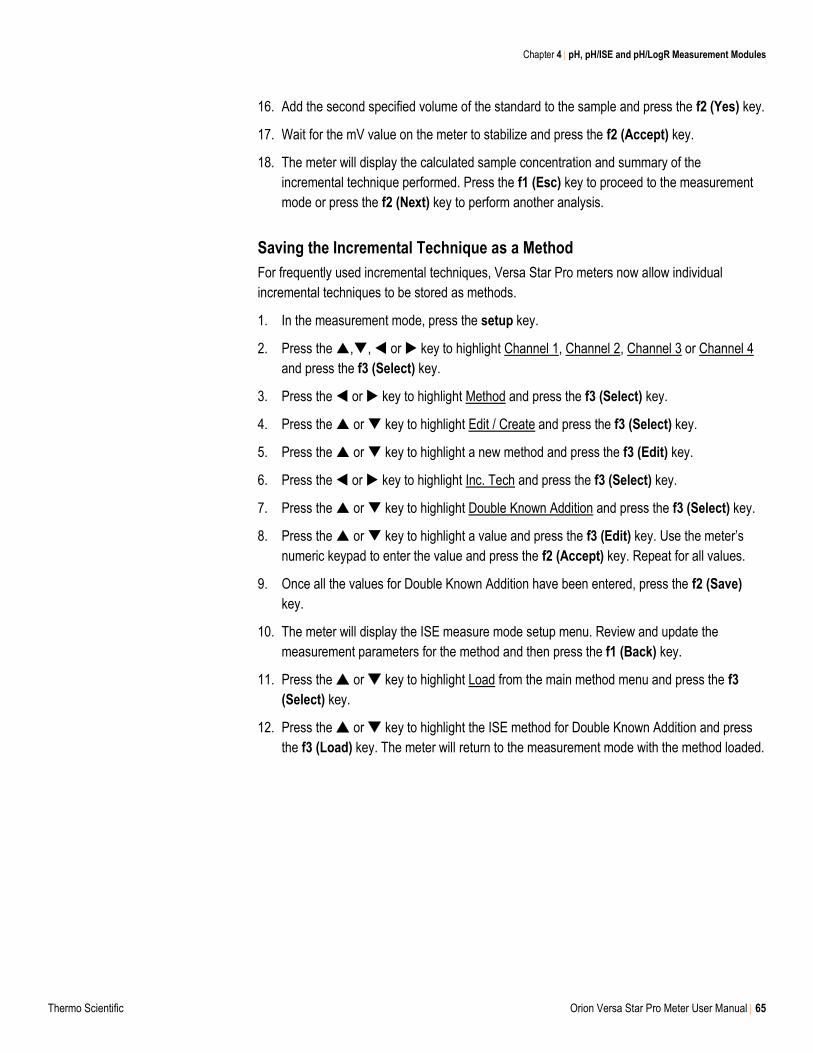
Chapter 4 pH, pH/ISE and pH/LogR Measurement Modules
Thermo Scientific Orion Versa Star Pro Meter User Manual 65
16. Add the second specified volume of the standard to the sample and press the f2 (Yes) key.
17. Wait for the mV value on the meter to stabilize and press the f2 (Accept) key.
18. The meter will display the calculated sample concentration and summary of the
incremental technique performed. Press the f1 (Esc) key to proceed to the measurement
mode or press the f2 (Next) key to perform another analysis.
Saving the Incremental Technique as a Method
For frequently used incremental techniques, Versa Star Pro meters now allow individual
incremental techniques to be stored as methods.
1. In the measurement mode, press the setup key.
2. Press the ,, or key to highlight Channel 1, Channel 2, Channel 3 or Channel 4
and press the f3 (Select) key.
3. Press the or key to highlight Method and press the f3 (Select) key.
4. Press the or key to highlight Edit / Create and press the f3 (Select) key.
5. Press the or key to highlight a new method and press the f3 (Edit) key.
6. Press the or key to highlight Inc. Tech and press the f3 (Select) key.
7. Press the or key to highlight Double Known Addition and press the f3 (Select) key.
8. Press the or key to highlight a value and press the f3 (Edit) key. Use the meter’s
numeric keypad to enter the value and press the f2 (Accept) key. Repeat for all values.
9. Once all the values for Double Known Addition have been entered, press the f2 (Save)
key.
10. The meter will display the ISE measure mode setup menu. Review and update the
measurement parameters for the method and then press the f1 (Back) key.
11. Press the or key to highlight Load from the main method menu and press the f3
(Select) key.
12. Press the or key to highlight the ISE method for Double Known Addition and press
the f3 (Load) key. The meter will return to the measurement mode with the method loaded.
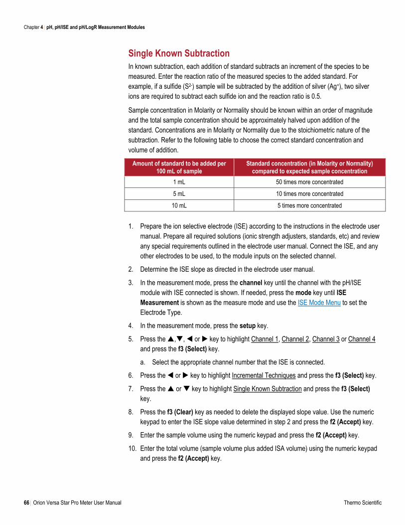
Chapter 4 pH, pH/ISE and pH/LogR Measurement Modules
66 Orion Versa Star Pro Meter User Manual Thermo Scientific
Single Known Subtraction
In known subtraction, each addition of standard subtracts an increment of the species to be
measured. Enter the reaction ratio of the measured species to the added standard. For
example, if a sulfide (S2-) sample will be subtracted by the addition of silver (Ag+), two silver
ions are required to subtract each sulfide ion and the reaction ratio is 0.5.
Sample concentration in Molarity or Normality should be known within an order of magnitude
and the total sample concentration should be approximately halved upon addition of the
standard. Concentrations are in Molarity or Normality due to the stoichiometric nature of the
subtraction. Refer to the following table to choose the correct standard concentration and
volume of addition.
Amount of standard to be added per 100 mL of sample
Standard concentration (in Molarity or Normality) compared to expected sample concentration
1 mL 50 times more concentrated
5 mL 10 times more concentrated
10 mL 5 times more concentrated
1. Prepare the ion selective electrode (ISE) according to the instructions in the electrode user
manual. Prepare all required solutions (ionic strength adjusters, standards, etc) and review
any special requirements outlined in the electrode user manual. Connect the ISE, and any
other electrodes to be used, to the module inputs on the selected channel.
2. Determine the ISE slope as directed in the electrode user manual.
3. In the measurement mode, press the channel key until the channel with the pH/ISE
module with ISE connected is shown. If needed, press the mode key until ISE
Measurement is shown as the measure mode and use the ISE Mode Menu to set the
Electrode Type.
4. In the measurement mode, press the setup key.
5. Press the ,, or key to highlight Channel 1, Channel 2, Channel 3 or Channel 4
and press the f3 (Select) key.
a. Select the appropriate channel number that the ISE is connected.
6. Press the or key to highlight Incremental Techniques and press the f3 (Select) key.
7. Press the or key to highlight Single Known Subtraction and press the f3 (Select)
key.
8. Press the f3 (Clear) key as needed to delete the displayed slope value. Use the numeric
keypad to enter the ISE slope value determined in step 2 and press the f2 (Accept) key.
9. Enter the sample volume using the numeric keypad and press the f2 (Accept) key.
10. Enter the total volume (sample volume plus added ISA volume) using the numeric keypad
and press the f2 (Accept) key.
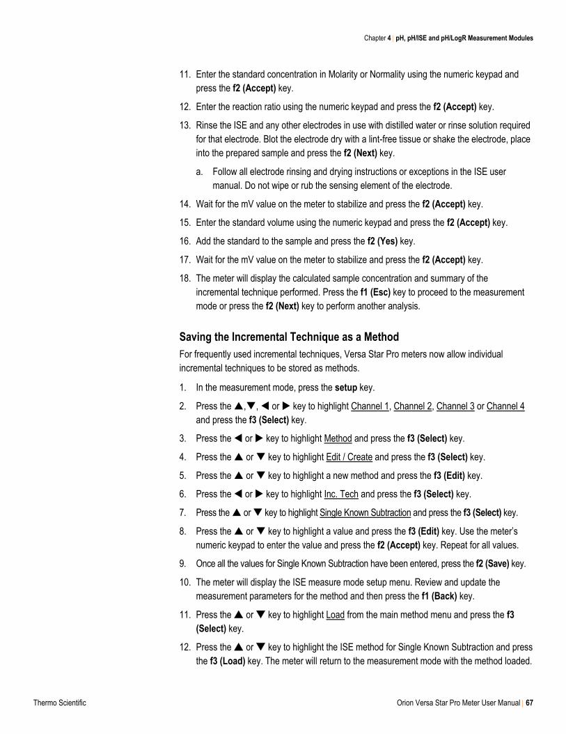
Chapter 4 pH, pH/ISE and pH/LogR Measurement Modules
Thermo Scientific Orion Versa Star Pro Meter User Manual 67
11. Enter the standard concentration in Molarity or Normality using the numeric keypad and
press the f2 (Accept) key.
12. Enter the reaction ratio using the numeric keypad and press the f2 (Accept) key.
13. Rinse the ISE and any other electrodes in use with distilled water or rinse solution required
for that electrode. Blot the electrode dry with a lint-free tissue or shake the electrode, place
into the prepared sample and press the f2 (Next) key.
a. Follow all electrode rinsing and drying instructions or exceptions in the ISE user
manual. Do not wipe or rub the sensing element of the electrode.
14. Wait for the mV value on the meter to stabilize and press the f2 (Accept) key.
15. Enter the standard volume using the numeric keypad and press the f2 (Accept) key.
16. Add the standard to the sample and press the f2 (Yes) key.
17. Wait for the mV value on the meter to stabilize and press the f2 (Accept) key.
18. The meter will display the calculated sample concentration and summary of the
incremental technique performed. Press the f1 (Esc) key to proceed to the measurement
mode or press the f2 (Next) key to perform another analysis.
Saving the Incremental Technique as a Method
For frequently used incremental techniques, Versa Star Pro meters now allow individual
incremental techniques to be stored as methods.
1. In the measurement mode, press the setup key.
2. Press the ,, or key to highlight Channel 1, Channel 2, Channel 3 or Channel 4
and press the f3 (Select) key.
3. Press the or key to highlight Method and press the f3 (Select) key.
4. Press the or key to highlight Edit / Create and press the f3 (Select) key.
5. Press the or key to highlight a new method and press the f3 (Edit) key.
6. Press the or key to highlight Inc. Tech and press the f3 (Select) key.
7. Press the or key to highlight Single Known Subtraction and press the f3 (Select) key.
8. Press the or key to highlight a value and press the f3 (Edit) key. Use the meter’s
numeric keypad to enter the value and press the f2 (Accept) key. Repeat for all values.
9. Once all the values for Single Known Subtraction have been entered, press the f2 (Save) key.
10. The meter will display the ISE measure mode setup menu. Review and update the
measurement parameters for the method and then press the f1 (Back) key.
11. Press the or key to highlight Load from the main method menu and press the f3
(Select) key.
12. Press the or key to highlight the ISE method for Single Known Subtraction and press
the f3 (Load) key. The meter will return to the measurement mode with the method loaded.
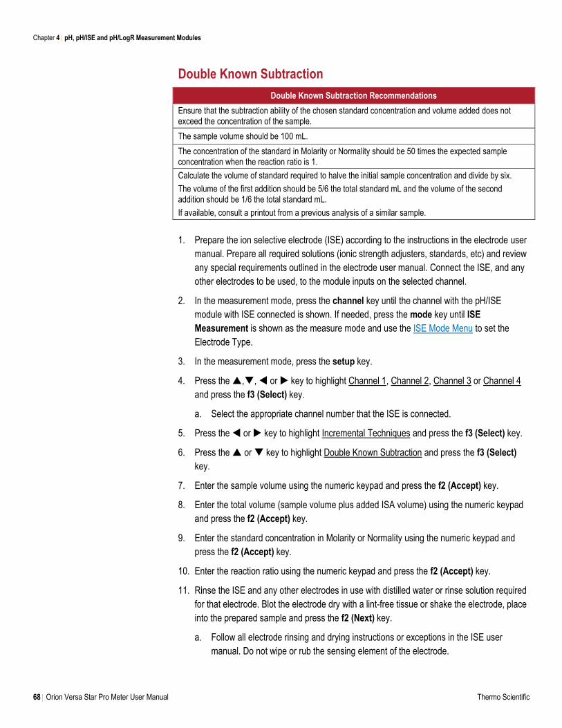
Chapter 4 pH, pH/ISE and pH/LogR Measurement Modules
68 Orion Versa Star Pro Meter User Manual Thermo Scientific
Double Known Subtraction
Double Known Subtraction Recommendations
Ensure that the subtraction ability of the chosen standard concentration and volume added does not exceed the concentration of the sample.
The sample volume should be 100 mL.
The concentration of the standard in Molarity or Normality should be 50 times the expected sample concentration when the reaction ratio is 1.
Calculate the volume of standard required to halve the initial sample concentration and divide by six.
The volume of the first addition should be 5/6 the total standard mL and the volume of the second addition should be 1/6 the total standard mL.
If available, consult a printout from a previous analysis of a similar sample.
1. Prepare the ion selective electrode (ISE) according to the instructions in the electrode user
manual. Prepare all required solutions (ionic strength adjusters, standards, etc) and review
any special requirements outlined in the electrode user manual. Connect the ISE, and any
other electrodes to be used, to the module inputs on the selected channel.
2. In the measurement mode, press the channel key until the channel with the pH/ISE
module with ISE connected is shown. If needed, press the mode key until ISE
Measurement is shown as the measure mode and use the ISE Mode Menu to set the
Electrode Type.
3. In the measurement mode, press the setup key.
4. Press the ,, or key to highlight Channel 1, Channel 2, Channel 3 or Channel 4
and press the f3 (Select) key.
a. Select the appropriate channel number that the ISE is connected.
5. Press the or key to highlight Incremental Techniques and press the f3 (Select) key.
6. Press the or key to highlight Double Known Subtraction and press the f3 (Select)
key.
7. Enter the sample volume using the numeric keypad and press the f2 (Accept) key.
8. Enter the total volume (sample volume plus added ISA volume) using the numeric keypad
and press the f2 (Accept) key.
9. Enter the standard concentration in Molarity or Normality using the numeric keypad and
press the f2 (Accept) key.
10. Enter the reaction ratio using the numeric keypad and press the f2 (Accept) key.
11. Rinse the ISE and any other electrodes in use with distilled water or rinse solution required
for that electrode. Blot the electrode dry with a lint-free tissue or shake the electrode, place
into the prepared sample and press the f2 (Next) key.
a. Follow all electrode rinsing and drying instructions or exceptions in the ISE user
manual. Do not wipe or rub the sensing element of the electrode.
Chapter 4 pH, pH/ISE and pH/LogR Measurement Modules
Thermo Scientific Orion Versa Star Pro Meter User Manual 69
12. Wait for the mV value on the meter to stabilize and press the f2 (Accept) key.
13. Enter the first standard volume using the numeric keypad and press the f2 (Accept) key.
14. Add the first specified volume of the standard to the sample and press the f2 (Yes) key.
15. Wait for the mV value on the meter to stabilize and press the f2 (Accept) key.
16. Enter the second standard volume using the numeric keypad and press the f2 (Accept)
key.
17. Add the second specified volume of the standard to the sample and press the f2 (Yes) key.
18. Wait for the mV value on the meter to stabilize and press the f2 (Accept) key.
19. The meter will display the calculated sample concentration and summary of the
incremental technique performed. Press the f1 (Esc) key to proceed to the measurement
mode or press the f2 (Next) key to perform another analysis.
Saving the Incremental Technique as a Method
For frequently used incremental techniques, Versa Star Pro meters now allow individual
incremental techniques to be stored as methods.
1. In the measurement mode, press the setup key.
2. Press the ,, or key to highlight Channel 1, Channel 2, Channel 3 or Channel 4
and press the f3 (Select) key.
3. Press the or key to highlight Method and press the f3 (Select) key.
4. Press the or key to highlight Edit / Create and press the f3 (Select) key.
5. Press the or key to highlight a new method and press the f3 (Edit) key.
6. Press the or key to highlight Inc. Tech and press the f3 (Select) key.
7. Press the or key to highlight Double Known Subtraction and press the f3 (Select)
key.
8. Press the or key to highlight a value and press the f3 (Edit) key. Use the meter’s
numeric keypad to enter the value and press the f2 (Accept) key. Repeat for all values.
9. Once all the values for Double Known Subtraction have been entered, press the f2 (Save)
key.
10. The meter will display the ISE measure mode setup menu. Review and update the
measurement parameters for the method and then press the f1 (Back) key.
11. Press the or key to highlight Load from the main method menu and press the f3
(Select) key.
12. Press the or key to highlight the ISE method for Double Known Subtraction and
press the f3 (Load) key. The meter will return to the measurement mode with the method
loaded.
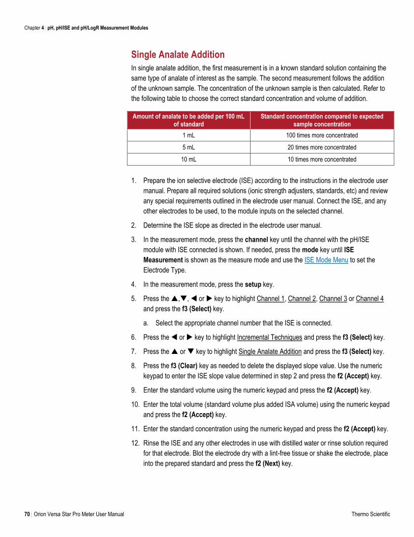
Chapter 4 pH, pH/ISE and pH/LogR Measurement Modules
70 Orion Versa Star Pro Meter User Manual Thermo Scientific
Single Analate Addition
In single analate addition, the first measurement is in a known standard solution containing the
same type of analate of interest as the sample. The second measurement follows the addition
of the unknown sample. The concentration of the unknown sample is then calculated. Refer to
the following table to choose the correct standard concentration and volume of addition.
Amount of analate to be added per 100 mL of standard
Standard concentration compared to expected sample concentration
1 mL 100 times more concentrated
5 mL 20 times more concentrated
10 mL 10 times more concentrated
1. Prepare the ion selective electrode (ISE) according to the instructions in the electrode user
manual. Prepare all required solutions (ionic strength adjusters, standards, etc) and review
any special requirements outlined in the electrode user manual. Connect the ISE, and any
other electrodes to be used, to the module inputs on the selected channel.
2. Determine the ISE slope as directed in the electrode user manual.
3. In the measurement mode, press the channel key until the channel with the pH/ISE
module with ISE connected is shown. If needed, press the mode key until ISE
Measurement is shown as the measure mode and use the ISE Mode Menu to set the
Electrode Type.
4. In the measurement mode, press the setup key.
5. Press the ,, or key to highlight Channel 1, Channel 2, Channel 3 or Channel 4
and press the f3 (Select) key.
a. Select the appropriate channel number that the ISE is connected.
6. Press the or key to highlight Incremental Techniques and press the f3 (Select) key.
7. Press the or key to highlight Single Analate Addition and press the f3 (Select) key.
8. Press the f3 (Clear) key as needed to delete the displayed slope value. Use the numeric
keypad to enter the ISE slope value determined in step 2 and press the f2 (Accept) key.
9. Enter the standard volume using the numeric keypad and press the f2 (Accept) key.
10. Enter the total volume (standard volume plus added ISA volume) using the numeric keypad
and press the f2 (Accept) key.
11. Enter the standard concentration using the numeric keypad and press the f2 (Accept) key.
12. Rinse the ISE and any other electrodes in use with distilled water or rinse solution required
for that electrode. Blot the electrode dry with a lint-free tissue or shake the electrode, place
into the prepared standard and press the f2 (Next) key.
Chapter 4 pH, pH/ISE and pH/LogR Measurement Modules
Thermo Scientific Orion Versa Star Pro Meter User Manual 71
a. Follow all electrode rinsing and drying instructions or exceptions in the ISE user
manual. Do not wipe or rub the sensing element of the electrode.
13. Wait for the mV value on the meter to stabilize and press the f2 (Accept) key.
14. Enter the analate/sample volume using the numeric keypad and press the f2 (Accept) key.
15. Add the analate/sample to the standard and press the f2 (Yes) key.
16. Wait for the mV value on the meter to stabilize and press the f2 (Accept) key.
17. The meter will display the calculated sample concentration and summary of the
incremental technique performed. Press the f1 (Esc) key to proceed to the measurement
mode or press the f2 (Next) key to perform another analysis.
Saving the Incremental Technique as a Method
For frequently used incremental techniques, Versa Star Pro meters now allow individual
incremental techniques to be stored as methods.
1. In the measurement mode, press the setup key.
2. Press the ,, or key to highlight Channel 1, Channel 2, Channel 3 or Channel 4
and press the f3 (Select) key.
3. Press the or key to highlight Method and press the f3 (Select) key.
4. Press the or key to highlight Edit / Create and press the f3 (Select) key.
5. Press the or key to highlight a new method and press the f3 (Edit) key.
6. Press the or key to highlight Inc. Tech and press the f3 (Select) key.
7. Press the or key to highlight Single Analate Addition and press the f3 (Select) key.
8. Press the or key to highlight a value and press the f3 (Edit) key. Use the meter’s
numeric keypad to enter the value and press the f2 (Accept) key. Repeat for all values.
9. Once all the values for Single Analate Addition have been entered, press the f2 (Save)
key.
10. The meter will display the ISE measure mode setup menu. Review and update the
measurement parameters for the method and then press the f1 (Back) key.
11. Press the or key to highlight Load from the main method menu and press the f3
(Select) key.
12. Press the or key to highlight the ISE method for Single Analate Addition and press
the f3 (Load) key. The meter will return to the measurement mode with the method loaded.
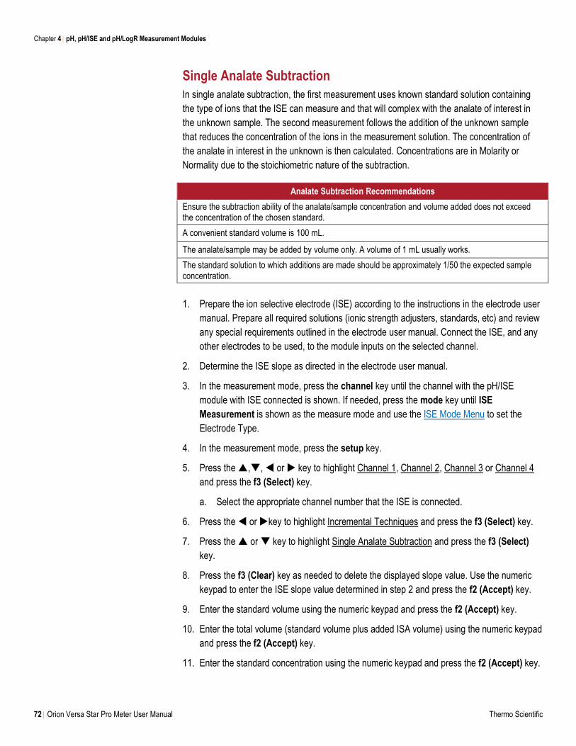
Chapter 4 pH, pH/ISE and pH/LogR Measurement Modules
72 Orion Versa Star Pro Meter User Manual Thermo Scientific
Single Analate Subtraction
In single analate subtraction, the first measurement uses known standard solution containing
the type of ions that the ISE can measure and that will complex with the analate of interest in
the unknown sample. The second measurement follows the addition of the unknown sample
that reduces the concentration of the ions in the measurement solution. The concentration of
the analate in interest in the unknown is then calculated. Concentrations are in Molarity or
Normality due to the stoichiometric nature of the subtraction.
Analate Subtraction Recommendations
Ensure the subtraction ability of the analate/sample concentration and volume added does not exceed the concentration of the chosen standard.
A convenient standard volume is 100 mL.
The analate/sample may be added by volume only. A volume of 1 mL usually works.
The standard solution to which additions are made should be approximately 1/50 the expected sample concentration.
1. Prepare the ion selective electrode (ISE) according to the instructions in the electrode user
manual. Prepare all required solutions (ionic strength adjusters, standards, etc) and review
any special requirements outlined in the electrode user manual. Connect the ISE, and any
other electrodes to be used, to the module inputs on the selected channel.
2. Determine the ISE slope as directed in the electrode user manual.
3. In the measurement mode, press the channel key until the channel with the pH/ISE
module with ISE connected is shown. If needed, press the mode key until ISE
Measurement is shown as the measure mode and use the ISE Mode Menu to set the
Electrode Type.
4. In the measurement mode, press the setup key.
5. Press the ,, or key to highlight Channel 1, Channel 2, Channel 3 or Channel 4
and press the f3 (Select) key.
a. Select the appropriate channel number that the ISE is connected.
6. Press the or key to highlight Incremental Techniques and press the f3 (Select) key.
7. Press the or key to highlight Single Analate Subtraction and press the f3 (Select)
key.
8. Press the f3 (Clear) key as needed to delete the displayed slope value. Use the numeric
keypad to enter the ISE slope value determined in step 2 and press the f2 (Accept) key.
9. Enter the standard volume using the numeric keypad and press the f2 (Accept) key.
10. Enter the total volume (standard volume plus added ISA volume) using the numeric keypad
and press the f2 (Accept) key.
11. Enter the standard concentration using the numeric keypad and press the f2 (Accept) key.
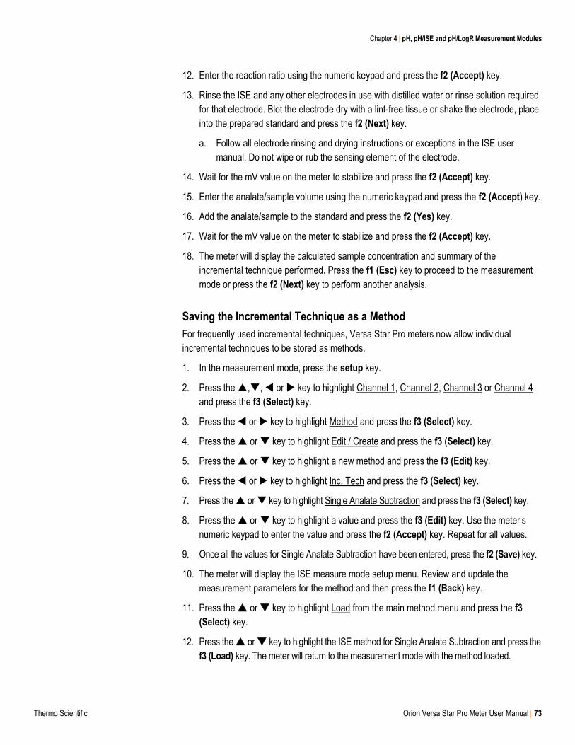
Chapter 4 pH, pH/ISE and pH/LogR Measurement Modules
Thermo Scientific Orion Versa Star Pro Meter User Manual 73
12. Enter the reaction ratio using the numeric keypad and press the f2 (Accept) key.
13. Rinse the ISE and any other electrodes in use with distilled water or rinse solution required
for that electrode. Blot the electrode dry with a lint-free tissue or shake the electrode, place
into the prepared standard and press the f2 (Next) key.
a. Follow all electrode rinsing and drying instructions or exceptions in the ISE user
manual. Do not wipe or rub the sensing element of the electrode.
14. Wait for the mV value on the meter to stabilize and press the f2 (Accept) key.
15. Enter the analate/sample volume using the numeric keypad and press the f2 (Accept) key.
16. Add the analate/sample to the standard and press the f2 (Yes) key.
17. Wait for the mV value on the meter to stabilize and press the f2 (Accept) key.
18. The meter will display the calculated sample concentration and summary of the
incremental technique performed. Press the f1 (Esc) key to proceed to the measurement
mode or press the f2 (Next) key to perform another analysis.
Saving the Incremental Technique as a Method
For frequently used incremental techniques, Versa Star Pro meters now allow individual
incremental techniques to be stored as methods.
1. In the measurement mode, press the setup key.
2. Press the ,, or key to highlight Channel 1, Channel 2, Channel 3 or Channel 4
and press the f3 (Select) key.
3. Press the or key to highlight Method and press the f3 (Select) key.
4. Press the or key to highlight Edit / Create and press the f3 (Select) key.
5. Press the or key to highlight a new method and press the f3 (Edit) key.
6. Press the or key to highlight Inc. Tech and press the f3 (Select) key.
7. Press the or key to highlight Single Analate Subtraction and press the f3 (Select) key.
8. Press the or key to highlight a value and press the f3 (Edit) key. Use the meter’s
numeric keypad to enter the value and press the f2 (Accept) key. Repeat for all values.
9. Once all the values for Single Analate Subtraction have been entered, press the f2 (Save) key.
10. The meter will display the ISE measure mode setup menu. Review and update the
measurement parameters for the method and then press the f1 (Back) key.
11. Press the or key to highlight Load from the main method menu and press the f3
(Select) key.
12. Press the or key to highlight the ISE method for Single Analate Subtraction and press the
f3 (Load) key. The meter will return to the measurement mode with the method loaded.
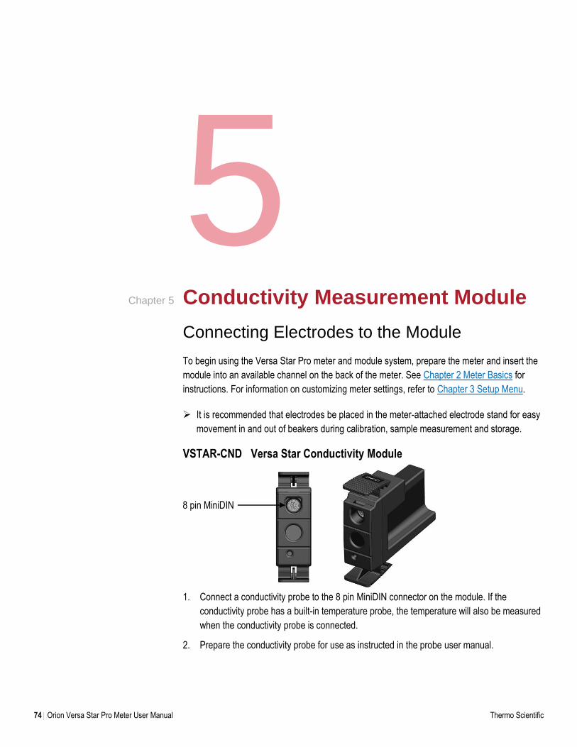
74 Orion Versa Star Pro Meter User Manual Thermo Scientific
5 Conductivity Measurement Module
Connecting Electrodes to the Module
To begin using the Versa Star Pro meter and module system, prepare the meter and insert the
module into an available channel on the back of the meter. See Chapter 2 Meter Basics for
instructions. For information on customizing meter settings, refer to Chapter 3 Setup Menu.
It is recommended that electrodes be placed in the meter-attached electrode stand for easy
movement in and out of beakers during calibration, sample measurement and storage.
VSTAR-CND Versa Star Conductivity Module
1. Connect a conductivity probe to the 8 pin MiniDIN connector on the module. If the
conductivity probe has a built-in temperature probe, the temperature will also be measured
when the conductivity probe is connected.
2. Prepare the conductivity probe for use as instructed in the probe user manual.
Chapter 5
8 pin MiniDIN
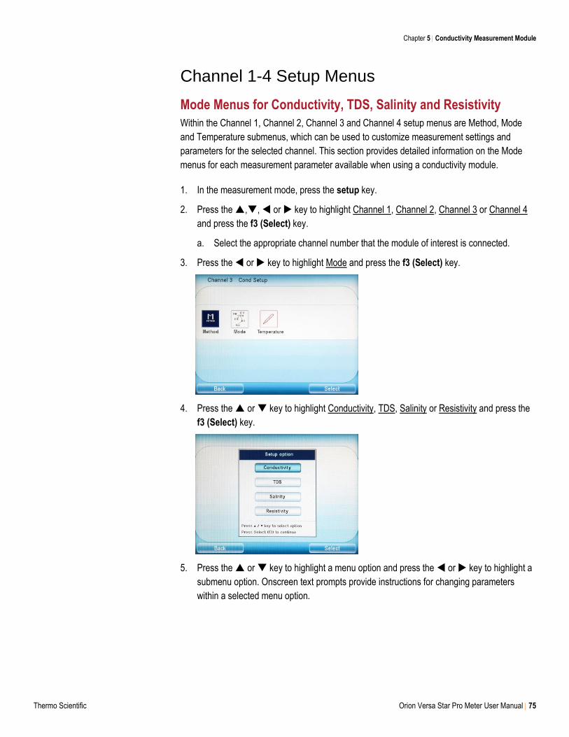
Chapter 5 Conductivity Measurement Module
Thermo Scientific Orion Versa Star Pro Meter User Manual 75
Channel 1-4 Setup Menus
Mode Menus for Conductivity, TDS, Salinity and Resistivity
Within the Channel 1, Channel 2, Channel 3 and Channel 4 setup menus are Method, Mode
and Temperature submenus, which can be used to customize measurement settings and
parameters for the selected channel. This section provides detailed information on the Mode
menus for each measurement parameter available when using a conductivity module.
1. In the measurement mode, press the setup key.
2. Press the ,, or key to highlight Channel 1, Channel 2, Channel 3 or Channel 4
and press the f3 (Select) key.
a. Select the appropriate channel number that the module of interest is connected.
3. Press the or key to highlight Mode and press the f3 (Select) key.
4. Press the or key to highlight Conductivity, TDS, Salinity or Resistivity and press the
f3 (Select) key.
5. Press the or key to highlight a menu option and press the or key to highlight a
submenu option. Onscreen text prompts provide instructions for changing parameters
within a selected menu option.
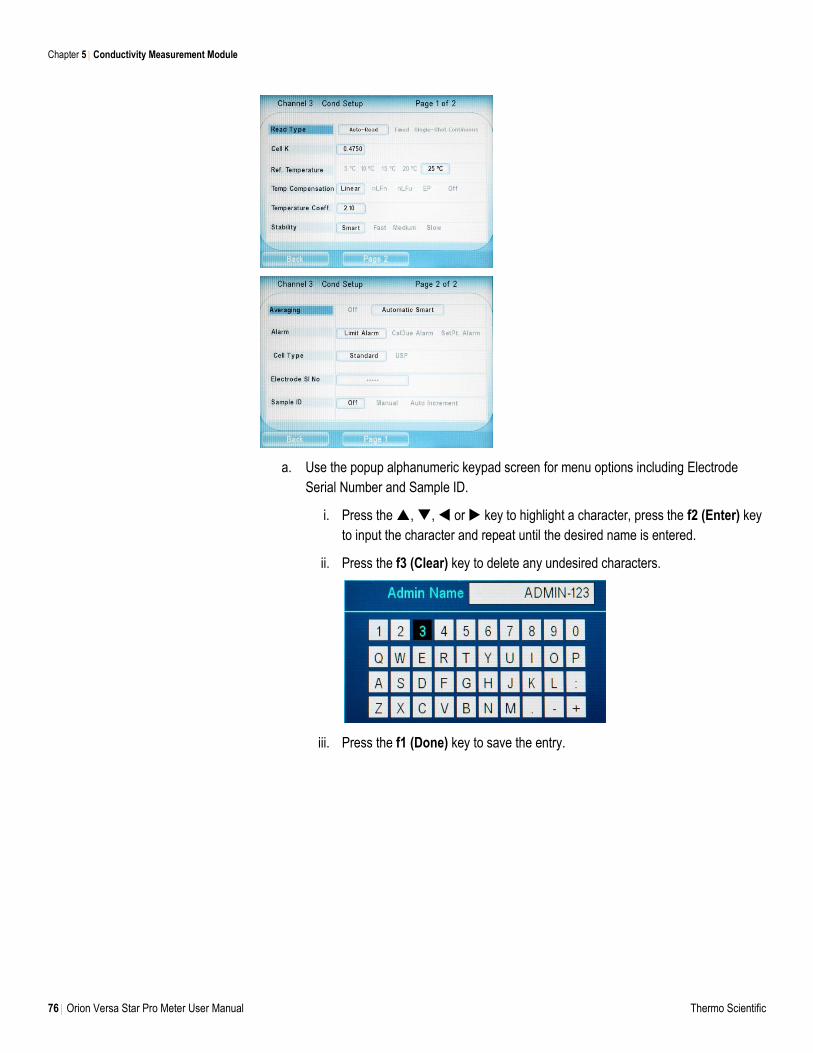
Chapter 5 Conductivity Measurement Module
76 Orion Versa Star Pro Meter User Manual Thermo Scientific
a. Use the popup alphanumeric keypad screen for menu options including Electrode
Serial Number and Sample ID.
i. Press the , , or key to highlight a character, press the f2 (Enter) key
to input the character and repeat until the desired name is entered.
ii. Press the f3 (Clear) key to delete any undesired characters.
iii. Press the f1 (Done) key to save the entry.
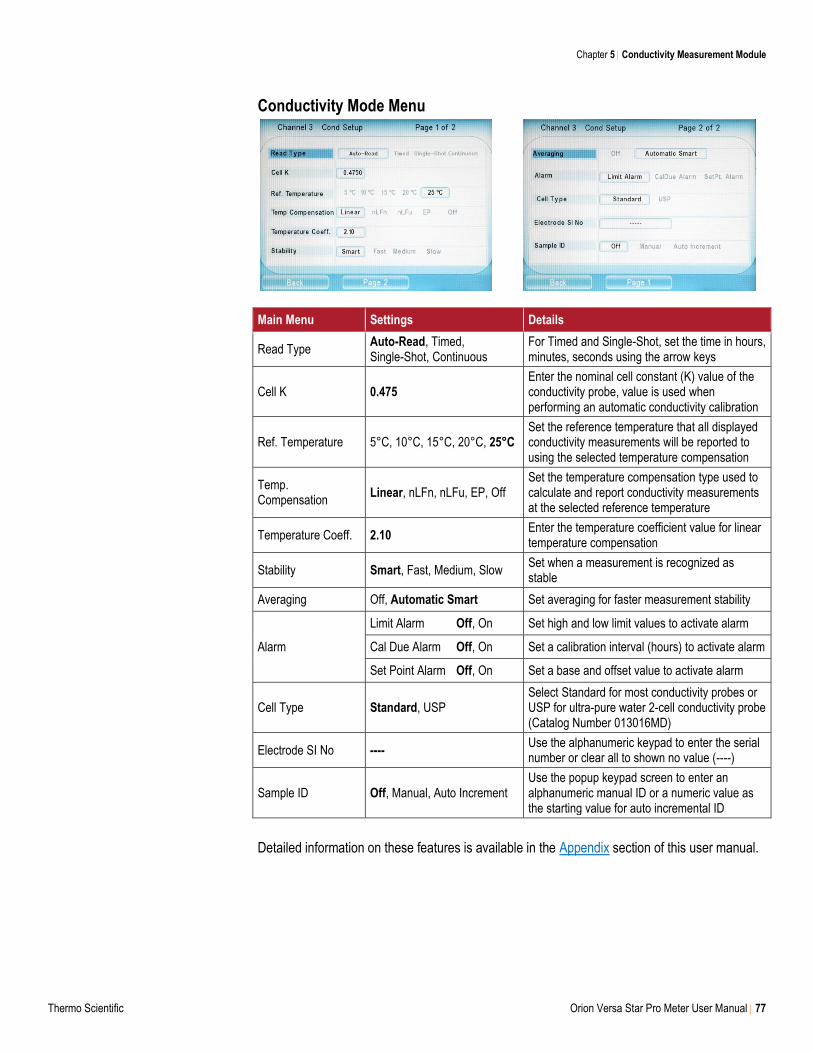
Chapter 5 Conductivity Measurement Module
Thermo Scientific Orion Versa Star Pro Meter User Manual 77
Conductivity Mode Menu
Main Menu Settings Details
Read Type Auto-Read, Timed, Single-Shot, Continuous
For Timed and Single-Shot, set the time in hours, minutes, seconds using the arrow keys
Cell K 0.475 Enter the nominal cell constant (K) value of the conductivity probe, value is used when performing an automatic conductivity calibration
Ref. Temperature 5°C, 10°C, 15°C, 20°C, 25°C Set the reference temperature that all displayed conductivity measurements will be reported to using the selected temperature compensation
Temp. Compensation
Linear, nLFn, nLFu, EP, Off Set the temperature compensation type used to calculate and report conductivity measurements at the selected reference temperature
Temperature Coeff. 2.10 Enter the temperature coefficient value for linear temperature compensation
Stability Smart, Fast, Medium, Slow Set when a measurement is recognized as stable
Averaging Off, Automatic Smart Set averaging for faster measurement stability
Alarm
Limit Alarm Off, On Set high and low limit values to activate alarm
Cal Due Alarm Off, On Set a calibration interval (hours) to activate alarm
Set Point Alarm Off, On Set a base and offset value to activate alarm
Cell Type Standard, USP Select Standard for most conductivity probes or USP for ultra-pure water 2-cell conductivity probe (Catalog Number 013016MD)
Electrode SI No ---- Use the alphanumeric keypad to enter the serial number or clear all to shown no value (----)
Sample ID Off, Manual, Auto Increment Use the popup keypad screen to enter an alphanumeric manual ID or a numeric value as the starting value for auto incremental ID
Detailed information on these features is available in the Appendix section of this user manual.
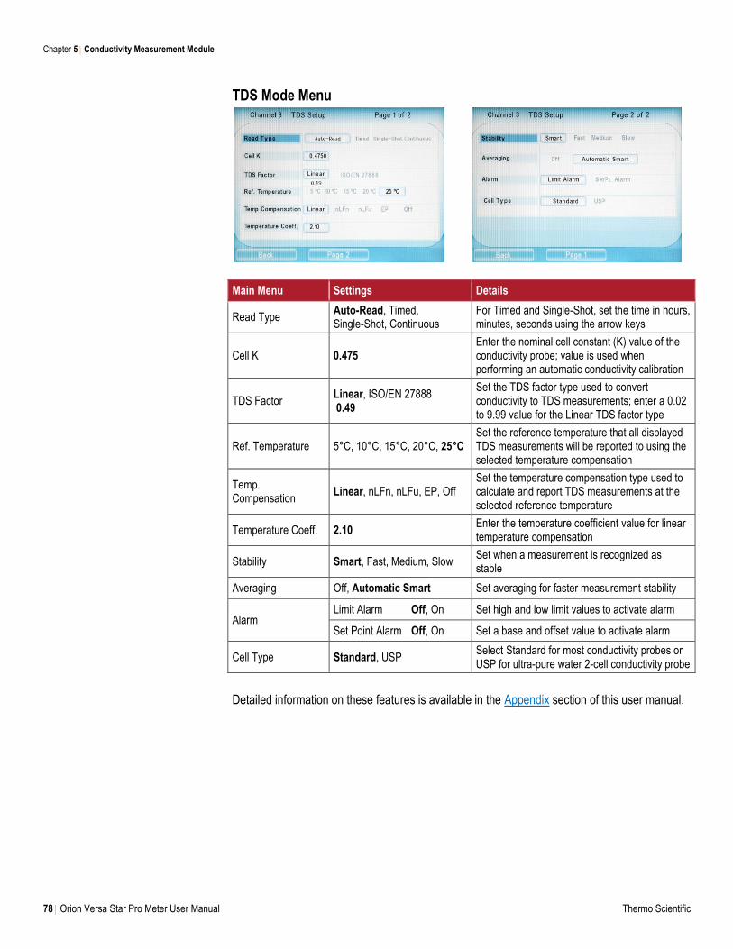
Chapter 5 Conductivity Measurement Module
78 Orion Versa Star Pro Meter User Manual Thermo Scientific
TDS Mode Menu
Main Menu Settings Details
Read Type Auto-Read, Timed, Single-Shot, Continuous
For Timed and Single-Shot, set the time in hours, minutes, seconds using the arrow keys
Cell K 0.475 Enter the nominal cell constant (K) value of the conductivity probe; value is used when performing an automatic conductivity calibration
TDS Factor Linear, ISO/EN 27888 0.49
Set the TDS factor type used to convert conductivity to TDS measurements; enter a 0.02 to 9.99 value for the Linear TDS factor type
Ref. Temperature 5°C, 10°C, 15°C, 20°C, 25°C Set the reference temperature that all displayed TDS measurements will be reported to using the selected temperature compensation
Temp. Compensation
Linear, nLFn, nLFu, EP, Off Set the temperature compensation type used to calculate and report TDS measurements at the selected reference temperature
Temperature Coeff. 2.10 Enter the temperature coefficient value for linear temperature compensation
Stability Smart, Fast, Medium, Slow Set when a measurement is recognized as stable
Averaging Off, Automatic Smart Set averaging for faster measurement stability
Alarm Limit Alarm Off, On Set high and low limit values to activate alarm
Set Point Alarm Off, On Set a base and offset value to activate alarm
Cell Type Standard, USP Select Standard for most conductivity probes or USP for ultra-pure water 2-cell conductivity probe
Detailed information on these features is available in the Appendix section of this user manual.
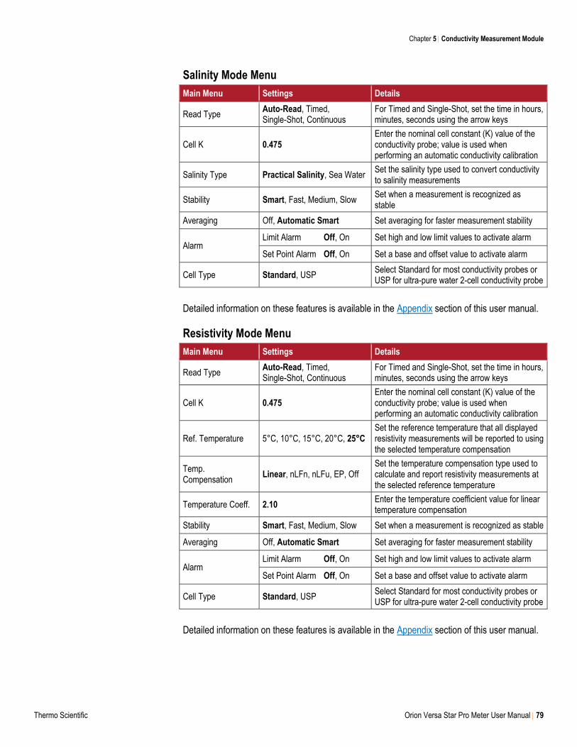
Chapter 5 Conductivity Measurement Module
Thermo Scientific Orion Versa Star Pro Meter User Manual 79
Salinity Mode Menu
Main Menu Settings Details
Read Type Auto-Read, Timed, Single-Shot, Continuous
For Timed and Single-Shot, set the time in hours, minutes, seconds using the arrow keys
Cell K 0.475 Enter the nominal cell constant (K) value of the conductivity probe; value is used when performing an automatic conductivity calibration
Salinity Type Practical Salinity, Sea Water Set the salinity type used to convert conductivity to salinity measurements
Stability Smart, Fast, Medium, Slow Set when a measurement is recognized as stable
Averaging Off, Automatic Smart Set averaging for faster measurement stability
Alarm Limit Alarm Off, On Set high and low limit values to activate alarm
Set Point Alarm Off, On Set a base and offset value to activate alarm
Cell Type Standard, USP Select Standard for most conductivity probes or USP for ultra-pure water 2-cell conductivity probe
Detailed information on these features is available in the Appendix section of this user manual.
Resistivity Mode Menu
Main Menu Settings Details
Read Type Auto-Read, Timed, Single-Shot, Continuous
For Timed and Single-Shot, set the time in hours, minutes, seconds using the arrow keys
Cell K 0.475 Enter the nominal cell constant (K) value of the conductivity probe; value is used when performing an automatic conductivity calibration
Ref. Temperature 5°C, 10°C, 15°C, 20°C, 25°C Set the reference temperature that all displayed resistivity measurements will be reported to using the selected temperature compensation
Temp. Compensation
Linear, nLFn, nLFu, EP, Off Set the temperature compensation type used to calculate and report resistivity measurements at the selected reference temperature
Temperature Coeff. 2.10 Enter the temperature coefficient value for linear temperature compensation
Stability Smart, Fast, Medium, Slow Set when a measurement is recognized as stable
Averaging Off, Automatic Smart Set averaging for faster measurement stability
Alarm Limit Alarm Off, On Set high and low limit values to activate alarm
Set Point Alarm Off, On Set a base and offset value to activate alarm
Cell Type Standard, USP Select Standard for most conductivity probes or USP for ultra-pure water 2-cell conductivity probe
Detailed information on these features is available in the Appendix section of this user manual.
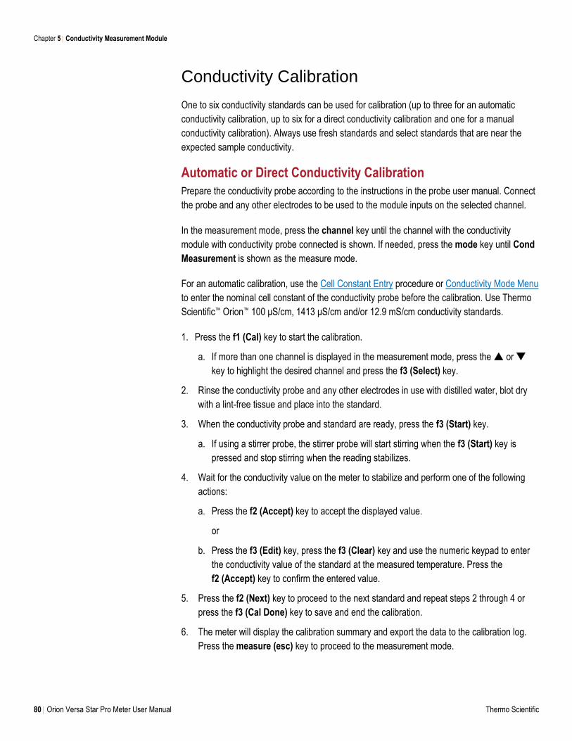
Chapter 5 Conductivity Measurement Module
80 Orion Versa Star Pro Meter User Manual Thermo Scientific
Conductivity Calibration
One to six conductivity standards can be used for calibration (up to three for an automatic
conductivity calibration, up to six for a direct conductivity calibration and one for a manual
conductivity calibration). Always use fresh standards and select standards that are near the
expected sample conductivity.
Automatic or Direct Conductivity Calibration
Prepare the conductivity probe according to the instructions in the probe user manual. Connect
the probe and any other electrodes to be used to the module inputs on the selected channel.
In the measurement mode, press the channel key until the channel with the conductivity
module with conductivity probe connected is shown. If needed, press the mode key until Cond
Measurement is shown as the measure mode.
For an automatic calibration, use the Cell Constant Entry procedure or Conductivity Mode Menu
to enter the nominal cell constant of the conductivity probe before the calibration. Use Thermo
Scientific™ Orion™ 100 μS/cm, 1413 μS/cm and/or 12.9 mS/cm conductivity standards.
1. Press the f1 (Cal) key to start the calibration.
a. If more than one channel is displayed in the measurement mode, press the or
key to highlight the desired channel and press the f3 (Select) key.
2. Rinse the conductivity probe and any other electrodes in use with distilled water, blot dry
with a lint-free tissue and place into the standard.
3. When the conductivity probe and standard are ready, press the f3 (Start) key.
a. If using a stirrer probe, the stirrer probe will start stirring when the f3 (Start) key is
pressed and stop stirring when the reading stabilizes.
4. Wait for the conductivity value on the meter to stabilize and perform one of the following
actions:
a. Press the f2 (Accept) key to accept the displayed value.
or
b. Press the f3 (Edit) key, press the f3 (Clear) key and use the numeric keypad to enter
the conductivity value of the standard at the measured temperature. Press the
f2 (Accept) key to confirm the entered value.
5. Press the f2 (Next) key to proceed to the next standard and repeat steps 2 through 4 or
press the f3 (Cal Done) key to save and end the calibration.
6. The meter will display the calibration summary and export the data to the calibration log.
Press the measure (esc) key to proceed to the measurement mode.
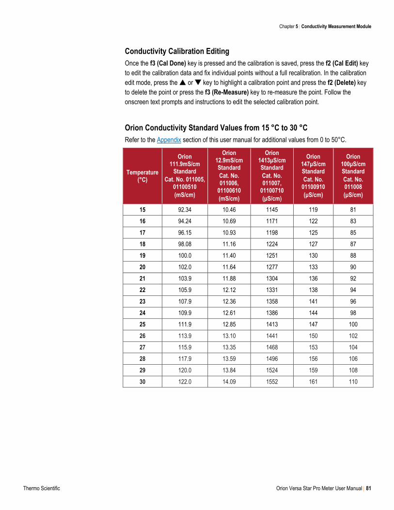
Chapter 5 Conductivity Measurement Module
Thermo Scientific Orion Versa Star Pro Meter User Manual 81
Conductivity Calibration Editing
Once the f3 (Cal Done) key is pressed and the calibration is saved, press the f2 (Cal Edit) key
to edit the calibration data and fix individual points without a full recalibration. In the calibration
edit mode, press the or key to highlight a calibration point and press the f2 (Delete) key
to delete the point or press the f3 (Re-Measure) key to re-measure the point. Follow the
onscreen text prompts and instructions to edit the selected calibration point.
Orion Conductivity Standard Values from 15 °C to 30 °C
Refer to the Appendix section of this user manual for additional values from 0 to 50°C.
Temperature (°C)
Orion 111.9mS/cm
Standard
Cat. No. 011005, 01100510
(mS/cm)
Orion 12.9mS/cm Standard
Cat. No. 011006,
01100610
(mS/cm)
Orion 1413μS/cm Standard
Cat. No. 011007,
01100710
(μS/cm)
Orion 147μS/cm Standard
Cat. No. 01100910
(μS/cm)
Orion 100μS/cm Standard
Cat. No. 011008
(μS/cm)
15 92.34 10.46 1145 119 81
16 94.24 10.69 1171 122 83
17 96.15 10.93 1198 125 85
18 98.08 11.16 1224 127 87
19 100.0 11.40 1251 130 88
20 102.0 11.64 1277 133 90
21 103.9 11.88 1304 136 92
22 105.9 12.12 1331 138 94
23 107.9 12.36 1358 141 96
24 109.9 12.61 1386 144 98
25 111.9 12.85 1413 147 100
26 113.9 13.10 1441 150 102
27 115.9 13.35 1468 153 104
28 117.9 13.59 1496 156 106
29 120.0 13.84 1524 159 108
30 122.0 14.09 1552 161 110
Chapter 5 Conductivity Measurement Module
82 Orion Versa Star Pro Meter User Manual Thermo Scientific
Cell Constant Entry (Manual Conductivity Calibration)
1. Press the f1 (Cal) key to start the calibration.
a. If more than one channel is displayed in the measurement mode, press the or
key to highlight the desired channel and press the f3 (Select) key.
2. Press the f2 (Cell K) key and wait for the cell constant value on the meter to stabilize.
3. Press the f2 (Accept) key to accept the displayed value or press the f3 (Edit) key, press
the f3 (Clear) key, use the numeric keypad to enter the cell constant value of the
conductivity probe and press the f2 (Accept) key to confirm the entered value.
4. The meter will save the entered cell constant value as the nominal cell constant of the
conductivity probe and return to the main calibration display. Press the measure (esc) key
to proceed to the measurement mode or perform the Automatic or Direct Conductivity
Calibration procedure.
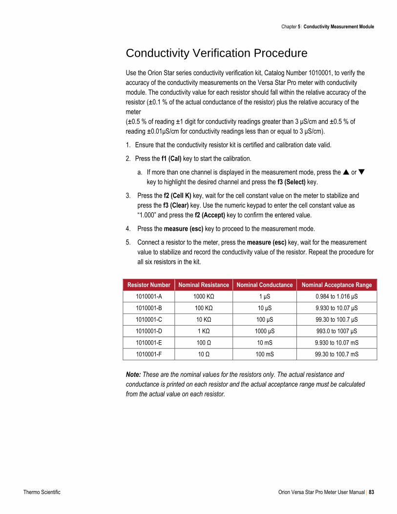
Chapter 5 Conductivity Measurement Module
Thermo Scientific Orion Versa Star Pro Meter User Manual 83
Conductivity Verification Procedure
Use the Orion Star series conductivity verification kit, Catalog Number 1010001, to verify the
accuracy of the conductivity measurements on the Versa Star Pro meter with conductivity
module. The conductivity value for each resistor should fall within the relative accuracy of the
resistor (±0.1 % of the actual conductance of the resistor) plus the relative accuracy of the
meter
(±0.5 % of reading ±1 digit for conductivity readings greater than 3 μS/cm and ±0.5 % of
reading ±0.01μS/cm for conductivity readings less than or equal to 3 μS/cm).
1. Ensure that the conductivity resistor kit is certified and calibration date valid.
2. Press the f1 (Cal) key to start the calibration.
a. If more than one channel is displayed in the measurement mode, press the or
key to highlight the desired channel and press the f3 (Select) key.
3. Press the f2 (Cell K) key, wait for the cell constant value on the meter to stabilize and
press the f3 (Clear) key. Use the numeric keypad to enter the cell constant value as
“1.000” and press the f2 (Accept) key to confirm the entered value.
4. Press the measure (esc) key to proceed to the measurement mode.
5. Connect a resistor to the meter, press the measure (esc) key, wait for the measurement
value to stabilize and record the conductivity value of the resistor. Repeat the procedure for
all six resistors in the kit.
Resistor Number Nominal Resistance Nominal Conductance Nominal Acceptance Range
1010001-A 1000 KΩ 1 μS 0.984 to 1.016 μS
1010001-B 100 KΩ 10 μS 9.930 to 10.07 μS
1010001-C 10 KΩ 100 μS 99.30 to 100.7 μS
1010001-D 1 KΩ 1000 μS 993.0 to 1007 μS
1010001-E 100 Ω 10 mS 9.930 to 10.07 mS
1010001-F 10 Ω 100 mS 99.30 to 100.7 mS
Note: These are the nominal values for the resistors only. The actual resistance and
conductance is printed on each resistor and the actual acceptance range must be calculated
from the actual value on each resistor.

84 Orion Versa Star Pro Meter User Manual Thermo Scientific
6 RDO/DO Measurement Module
Connecting Electrodes to the Module
To begin using the Versa Star Pro meter and module system, prepare the meter and insert the
module into an available channel on the back of the meter. See Chapter 2 Meter Basics for
instructions. For information on customizing meter settings, refer to Chapter 3 Setup Menu.
It is recommended that electrodes be placed in the meter-attached electrode stand for easy
movement in and out of beakers during calibration, sample measurement and storage.
VSTAR-RD Versa Star RDO/Dissolved Oxygen Module
1. Connect the dissolved oxygen (DO) probe to the 9 pin MiniDIN connector on the module.
The temperature will also be measured when the DO probe is connected.
An Orion RDO optical DO probe or Orion polarographic DO probe can be connected
and the meter will automatically detect the probe type.
2. Prepare the DO probe for use as instructed in the probe user manual.
Chapter 6
9 pin MiniDIN
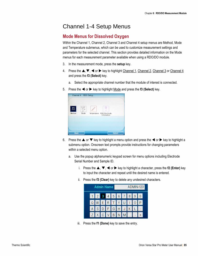
Chapter 6 RDO/DO Measurement Module
Thermo Scientific Orion Versa Star Pro Meter User Manual 85
Channel 1-4 Setup Menus
Mode Menus for Dissolved Oxygen
Within the Channel 1, Channel 2, Channel 3 and Channel 4 setup menus are Method, Mode
and Temperature submenus, which can be used to customize measurement settings and
parameters for the selected channel. This section provides detailed information on the Mode
menus for each measurement parameter available when using a RDO/DO module.
3. In the measurement mode, press the setup key.
4. Press the ,, or key to highlight Channel 1, Channel 2, Channel 3 or Channel 4
and press the f3 (Select) key.
a. Select the appropriate channel number that the module of interest is connected.
5. Press the or key to highlight Mode and press the f3 (Select) key.
6. Press the or key to highlight a menu option and press the or key to highlight a
submenu option. Onscreen text prompts provide instructions for changing parameters
within a selected menu option.
a. Use the popup alphanumeric keypad screen for menu options including Electrode
Serial Number and Sample ID.
i. Press the , , or key to highlight a character, press the f2 (Enter) key
to input the character and repeat until the desired name is entered.
ii. Press the f3 (Clear) key to delete any undesired characters.
iii. Press the f1 (Done) key to save the entry.
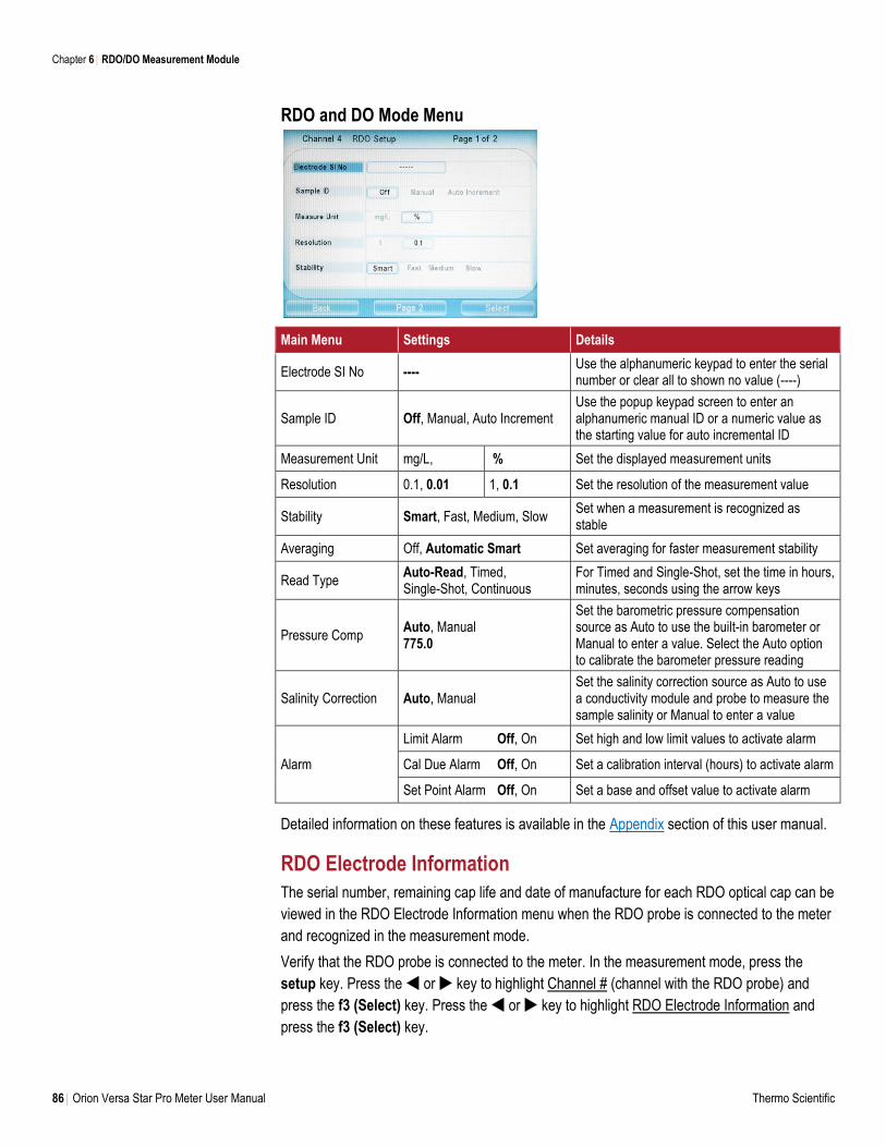
Chapter 6 RDO/DO Measurement Module
86 Orion Versa Star Pro Meter User Manual Thermo Scientific
RDO and DO Mode Menu
Main Menu Settings Details
Electrode SI No ---- Use the alphanumeric keypad to enter the serial number or clear all to shown no value (----)
Sample ID Off, Manual, Auto Increment Use the popup keypad screen to enter an alphanumeric manual ID or a numeric value as the starting value for auto incremental ID
Measurement Unit mg/L, % Set the displayed measurement units
Resolution 0.1, 0.01 1, 0.1 Set the resolution of the measurement value
Stability Smart, Fast, Medium, Slow Set when a measurement is recognized as stable
Averaging Off, Automatic Smart Set averaging for faster measurement stability
Read Type Auto-Read, Timed, Single-Shot, Continuous
For Timed and Single-Shot, set the time in hours, minutes, seconds using the arrow keys
Pressure Comp Auto, Manual 775.0
Set the barometric pressure compensation source as Auto to use the built-in barometer or Manual to enter a value. Select the Auto option to calibrate the barometer pressure reading
Salinity Correction Auto, Manual Set the salinity correction source as Auto to use a conductivity module and probe to measure the sample salinity or Manual to enter a value
Alarm
Limit Alarm Off, On Set high and low limit values to activate alarm
Cal Due Alarm Off, On Set a calibration interval (hours) to activate alarm
Set Point Alarm Off, On Set a base and offset value to activate alarm
Detailed information on these features is available in the Appendix section of this user manual.
RDO Electrode Information
The serial number, remaining cap life and date of manufacture for each RDO optical cap can be
viewed in the RDO Electrode Information menu when the RDO probe is connected to the meter
and recognized in the measurement mode.
Verify that the RDO probe is connected to the meter. In the measurement mode, press the
setup key. Press the or key to highlight Channel # (channel with the RDO probe) and
press the f3 (Select) key. Press the or key to highlight RDO Electrode Information and
press the f3 (Select) key.
Chapter 6 RDO/DO Measurement Module
Thermo Scientific Orion Versa Star Pro Meter User Manual 87
Dissolved Oxygen Calibration
Note: A polarographic DO probe must be polarized prior to use. The probe is continuously
polarized when connected to the meter. If the polarographic DO probe is new, has been
serviced or has not been connected to the meter: connect the probe to the meter, power on the
meter and wait 30 minutes for the probe to polarize.
The Versa Star Pro meter with RDO/DO module offers the following calibration options:
Water Saturated Air – This is the simplest and most accurate method and uses the
calibration sleeve included with most DO probes. For best accuracy, the calibration
temperature should match the expected sample temperature. Moisten the sponge in the
calibration sleeve with distilled water and insert the probe into the sleeve. A BOD bottle can
be used with just enough distilled water to cover the bottom without touching the probe.
Air Saturated Water – This method uses water that is 100% saturated with air. Bubble air
into a water sample for an extended period, preferably overnight.
Manual (Winkler) – This method uses a water sample with a known concentration of
dissolved oxygen and is typically used to calibrate the DO probe to the value achieved by a
Winkler titration. Due to possible titration errors, this method is inherently less accurate.
Set Zero – This method uses an oxygen free solution to add a zero point to an existing
Water Saturated Air or Air Saturated Water calibration. This calibration is generally
recommended when measurements are below 10% saturation or 1 mg/L.
Prepare the DO probe according to the instructions in the probe user manual. Connect the
probe and any other electrodes to be used to the module inputs on the selected channel.
In the measurement mode, press the channel key until the channel with the RDO/DO module
with DO probe connected is shown.
Water Saturated Air Calibration
1. Press the f1 (Cal) key to start the calibration.
a. If more than one channel is displayed in the measurement mode, press the or
key to highlight the desired channel and press the f3 (Select) key.
2. Press the or key to highlight Water Saturated Air and press the f3 (Select) key.
3. Prepare the DO probe and calibration sleeve and allow them to reach equilibrium.
4. When the DO probe and calibration sleeve are ready, press the f3 (Start) key.
5. Wait for the dissolved oxygen value on the meter to stabilize and press the f2 (Accept)
key.
a. With a polarographic DO probe, 102.3 % will be displayed when the reading stabilizes.
b. With an RDO optical DO probe, 100.0 % will be displayed when the reading stabilizes.
Chapter 6 RDO/DO Measurement Module
88 Orion Versa Star Pro Meter User Manual Thermo Scientific
6. Press the f3 (Cal Done) key to save and end the calibration.
7. The meter will display the calibration summary and export the data to the calibration log.
Press the measure (esc) key to proceed to the measurement mode.
Air Saturated Water Calibration
1. Press the f1 (Cal) key to start the calibration.
a. If more than one channel is displayed in the measurement mode, press the or
key to highlight the desired channel and press the f3 (Select) key.
2. Press the or key to highlight Air Saturated Water and press the f3 (Select) key.
3. Prepare the DO probe and 100% air-saturated water and allow them to reach equilibrium.
a. Use plastic paraffin film to seal the open area between the DO probe and vessel
containing the 100% air-saturated water.
4. When the DO probe and calibration apparatus are ready, press the f3 (Start) key.
a. If using a stirrer probe, the stirrer probe will start stirring when the f3 (Start) key is
pressed and stop stirring when the reading stabilizes.
5. Wait for the dissolved oxygen value on the meter to stabilize and press the f2 (Accept)
key.
a. 100.0 % will be displayed when the reading stabilizes.
6. Press the f3 (Cal Done) key to save and end the calibration.
7. The meter will display the calibration summary and export the data to the calibration log.
Press the measure (esc) key to proceed to the measurement mode.
Manual (Winkler) Calibration
1. Press the f1 (Cal) key to start the calibration.
a. If more than one channel is displayed in the measurement mode, press the or
key to highlight the desired channel and press the f3 (Select) key.
2. Press the ▲ or ▼ key to highlight Manual and press the f3 (Select) key.
3. Prepare the DO probe and calibration solution and allow them to reach equilibrium.
a. Use plastic paraffin film to seal the open area between the DO probe and vessel
containing the calibration solution.
4. When the DO probe and calibration apparatus are ready, press the f3 (Start) key.
a. If using a stirrer probe, the stirrer probe will start stirring when the f3 (Start) key is
pressed and stop stirring when the reading stabilizes.
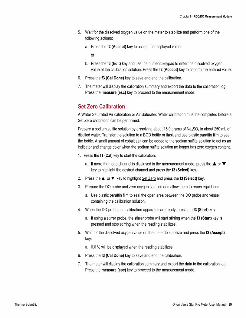
Chapter 6 RDO/DO Measurement Module
Thermo Scientific Orion Versa Star Pro Meter User Manual 89
5. Wait for the dissolved oxygen value on the meter to stabilize and perform one of the
following actions:
a. Press the f2 (Accept) key to accept the displayed value.
or
b. Press the f3 (Edit) key and use the numeric keypad to enter the dissolved oxygen
value of the calibration solution. Press the f2 (Accept) key to confirm the entered value.
6. Press the f3 (Cal Done) key to save and end the calibration.
7. The meter will display the calibration summary and export the data to the calibration log.
Press the measure (esc) key to proceed to the measurement mode.
Set Zero Calibration
A Water Saturated Air calibration or Air Saturated Water calibration must be completed before a
Set Zero calibration can be performed.
Prepare a sodium sulfite solution by dissolving about 15.0 grams of Na2SO3 in about 250 mL of
distilled water. Transfer the solution to a BOD bottle or flask and use plastic paraffin film to seal
the bottle. A small amount of cobalt salt can be added to the sodium sulfite solution to act as an
indicator and change color when the sodium sulfite solution no longer has zero oxygen content.
1. Press the f1 (Cal) key to start the calibration.
a. If more than one channel is displayed in the measurement mode, press the or
key to highlight the desired channel and press the f3 (Select) key.
2. Press the ▲ or ▼ key to highlight Set Zero and press the f3 (Select) key.
3. Prepare the DO probe and zero oxygen solution and allow them to reach equilibrium.
a. Use plastic paraffin film to seal the open area between the DO probe and vessel
containing the calibration solution.
4. When the DO probe and calibration apparatus are ready, press the f3 (Start) key.
a. If using a stirrer probe, the stirrer probe will start stirring when the f3 (Start) key is
pressed and stop stirring when the reading stabilizes.
5. Wait for the dissolved oxygen value on the meter to stabilize and press the f2 (Accept)
key.
a. 0.0 % will be displayed when the reading stabilizes.
6. Press the f3 (Cal Done) key to save and end the calibration.
7. The meter will display the calibration summary and export the data to the calibration log.
Press the measure (esc) key to proceed to the measurement mode.
90 Orion Versa Star Pro Meter User Manual Thermo Scientific
7 Meter Measurements
Measurement Overview
The type of module connected to each of the four channels on the Versa Star Pro meter will
define the measurement capability of that channel.
Versa Star Module Measurement Capabilities
pH module pH, mV, relative mV or ORP with temperature
pH/ISE module pH, mV, relative mV, ORP or concentration (ISE) with temperature
pH/LogR module pH, mV or ORP with temperature/LogR temperature
Conductivity module Conductivity, TDS, salinity or resistivity with temperature
RDO/DO module Dissolved oxygen as % saturation or concentration with temperature
When two or more modules are connected to the meter, pressing the channel key will change
the number and combination of channels displayed in the measurement mode. Each channel
can be displayed individually or two to four channels can be displayed simultaneously.
The information shown in the measurement mode can be customized using the Instrument
Settings setup menu. The channel number, measure mode, method, stability indicator,
temperature, secondary measurement parameter, calibration details, user ID, sample ID and
electrode serial number can each be shown or hidden. Hiding these items in the measurement
display will increase the font size of the main measurement value in the single channel display.
Use the Buzzer – Ready setting in the Instrument Settings setup menu to enable an audible
beep when a measurement becomes stable.
Chapter 7
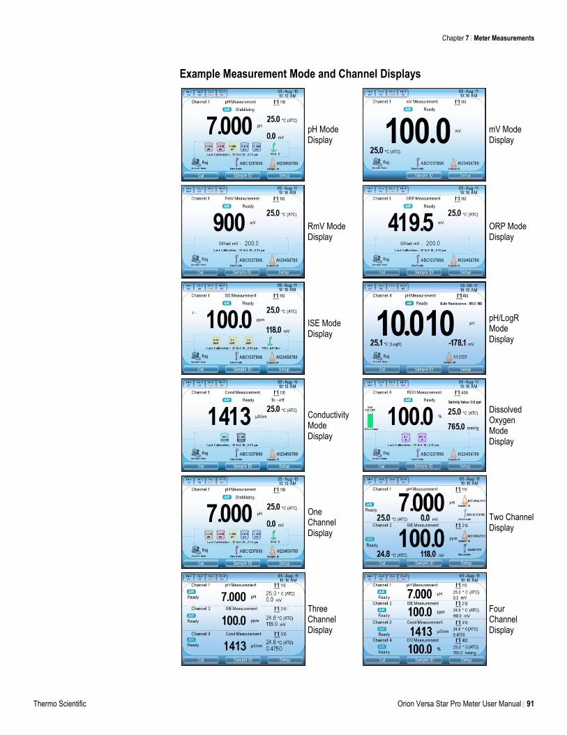
Chapter 7 Meter Measurements
Thermo Scientific Orion Versa Star Pro Meter User Manual 91
Example Measurement Mode and Channel Displays
pH Mode Display
mV Mode Display
RmV Mode Display
ORP Mode Display
ISE Mode Display
pH/LogR Mode Display
Conductivity Mode Display
Dissolved Oxygen Mode Display
One Channel Display
Two Channel Display
Three Channel Display
Four Channel Display
Chapter 7 Meter Measurements
92 Orion Versa Star Pro Meter User Manual Thermo Scientific
Measurement Read Types
Versa Star Pro meters have four options for the measurement read type – Auto-Read, Timed,
Single-Shot and Continuous. The read type determines how the meter takes a measurement
and when the measurement is sent to the data log and external device. The read type is set
individually for each channel and measure mode using the Mode setup menu described in each
module chapter – Mode Menus for pH, mV, Relative mV, ORP and ISE, Mode Menus for
Conductivity, TDS, Salinity and Resistivity and Mode Menus for Dissolved Oxygen.
1. In the measurement mode, press the setup key.
2. Press the or key to highlight a channel setup menu and press the f3 (Select) key.
3. Press the or key to highlight Mode and press the f3 (Select) key.
4. Press the or key to highlight the appropriate measure mode and press the f3
(Select) key. (Step not applicable for channels using the RDO/DO module)
5. Press the or key to highlight Read Type and press the or key to highlight Auto-
Read, Timed, Single-Shot or Continuous as the read type.
a. For Timed and Single-Shot, enter the time value using the or key to scroll to the
hours (HH), minutes (MM) or seconds (SS) field and the or key to increase or
decrease the value. Press the f1 (Done) key to confirm the value.
6. Press the measure (esc) key to return to the measurement mode.
Auto-Read
When Auto-Read is selected as the read type, a measurement is initiated by pressing the
measure (esc) key in the measurement mode. The changing measurement value is shown as
it stabilizes and the AR icon will blink. Once the value is stable, the measurement is locked and
held on the display and the AR icon will remain solid. To start a new measurement, press the
measure (esc) key.
Depending on the meter communication settings in the Instrument Settings setup menu, the
locked measurement value will be exported to the data log, printer and/or computer.
Timed
When Timed is selected as the read type and a time interval is entered, measurements are
recorded at the predefined time intervals. The meter will continue to record measurements at
the predefined time intervals until the measurement mode is exited. Measurements are
continuously updated on the display and the Stabilizing and Ready icons specify the
measurement value stability.
Depending on the meter communication settings in the Instrument Settings setup menu, the
recorded measurement values will be exported to the data log, printer and/or computer.
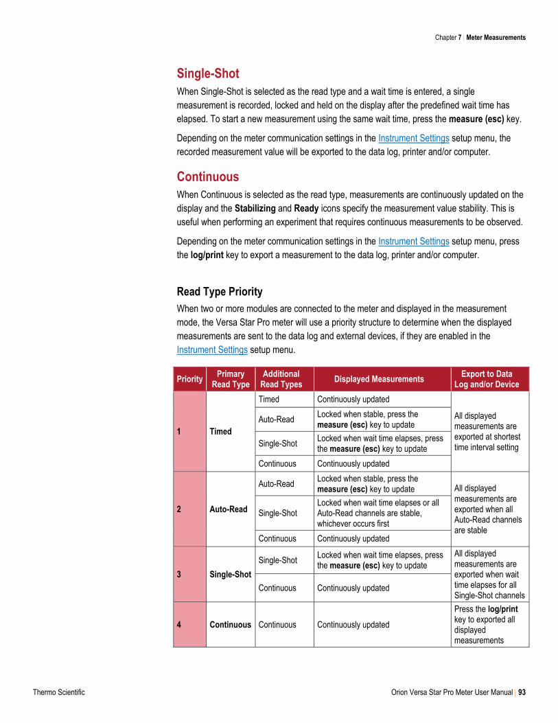
Chapter 7 Meter Measurements
Thermo Scientific Orion Versa Star Pro Meter User Manual 93
Single-Shot
When Single-Shot is selected as the read type and a wait time is entered, a single
measurement is recorded, locked and held on the display after the predefined wait time has
elapsed. To start a new measurement using the same wait time, press the measure (esc) key.
Depending on the meter communication settings in the Instrument Settings setup menu, the
recorded measurement value will be exported to the data log, printer and/or computer.
Continuous
When Continuous is selected as the read type, measurements are continuously updated on the
display and the Stabilizing and Ready icons specify the measurement value stability. This is
useful when performing an experiment that requires continuous measurements to be observed.
Depending on the meter communication settings in the Instrument Settings setup menu, press
the log/print key to export a measurement to the data log, printer and/or computer.
Read Type Priority
When two or more modules are connected to the meter and displayed in the measurement
mode, the Versa Star Pro meter will use a priority structure to determine when the displayed
measurements are sent to the data log and external devices, if they are enabled in the
Instrument Settings setup menu.
Priority Primary
Read Type Additional
Read Types Displayed Measurements
Export to Data Log and/or Device
1 Timed
Timed Continuously updated
All displayed measurements are exported at shortest time interval setting
Auto-Read Locked when stable, press the measure (esc) key to update
Single-Shot Locked when wait time elapses, press the measure (esc) key to update
Continuous Continuously updated
2 Auto-Read
Auto-Read Locked when stable, press the measure (esc) key to update All displayed
measurements are exported when all Auto-Read channels are stable
Single-Shot Locked when wait time elapses or all Auto-Read channels are stable, whichever occurs first
Continuous Continuously updated
3 Single-Shot
Single-Shot Locked when wait time elapses, press the measure (esc) key to update
All displayed measurements are exported when wait time elapses for all Single-Shot channels
Continuous Continuously updated
4 Continuous Continuous Continuously updated
Press the log/print key to exported all displayed measurements
Chapter 7 Meter Measurements
94 Orion Versa Star Pro Meter User Manual Thermo Scientific
Measurement Procedure
As needed, customize the information shown in the measurement mode using the Instrument
Settings setup menu. If two or more modules are connected to the meter, while in the
measurement mode press the channel key until the desired combination of meter channels are
shown. Select the read type for all meter channels shown in the measurement mode.
Prepare the electrodes according to the instructions in the electrode user manuals. Connect the
electrodes to the module inputs on the displayed channels. Make sure the electrodes are
properly calibrated and working correctly.
1. Rinse the electrodes with distilled water or appropriate solution, blot dry with a lint-free
tissue and place into the sample.
2. Start the measurement and wait for the reading to stabilize or reach the predefined time.
a. Auto-Read: Press the measure (esc) key to start the measurement. If using a stirrer
probe, the stirrer probe will start stirring when the measure (esc) key is pressed and
stop stirring when the measurement stabilizes.
b. Timed: Measurements will start immediately when in the measurement mode. If using a
stirrer probe, press the stirrer key to start and stop stirring.
c. Single-Shot: Press the measure (esc) key to start the measurement. If using a stirrer
probe, the stirrer probe will start stirring when the measure (esc) key is pressed and
stop stirring when the predefined wait time has elapsed.
d. Continuous: Measurements will start immediately when in the measurement mode. If
using a stirrer probe, press the stirrer key to start and stop stirring.
3. Once the measurement is stable or reaches the set time, record all applicable parameters.
a. Auto-Read: Once the measurement is stable, it will be locked and held on the display
and the AR icon will remain solid. If the data log function is enabled, the measurement
will be exported to the data log.
b. Timed: Measurements will be recorded at the predefined time interval. If the data log
function is enabled, the icon will be shown when each time interval has elapsed and
the measurement is exported to the data log.
c. Single-Shot: Once the predefined wait time has elapsed, the measurement will be
locked and held on the display. If the data log function is enabled, the measurement will
be exported to the data log.
d. Continuous: The flashing Stabilizing icon will update to the solid Ready icon when the
measurement is stable. If the data log function is enabled, press the log/print key to
export the measurement to the data log.
4. Remove the electrodes from the sample, rinse with distilled water or appropriate solution,
blot dry with a lint-free tissue and place into the next sample.
5. Repeat steps 2 through 4 for all samples. When all samples have been measured, store
the electrodes according to the instructions in the electrode user manuals.
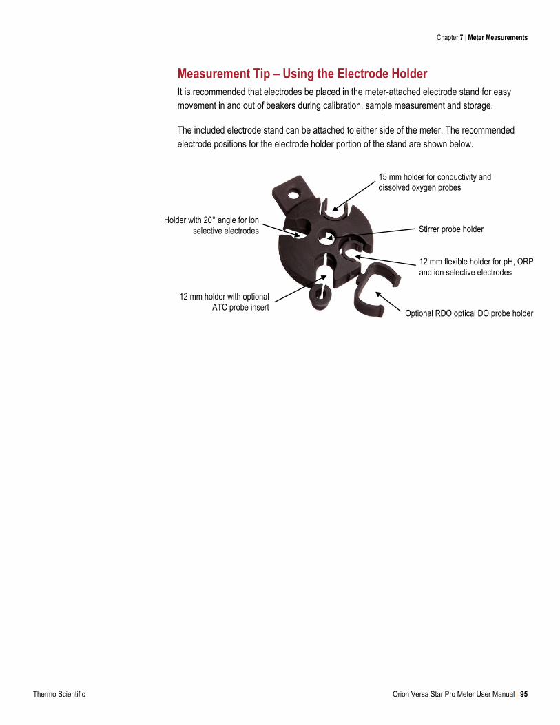
Chapter 7 Meter Measurements
Thermo Scientific Orion Versa Star Pro Meter User Manual 95
Measurement Tip – Using the Electrode Holder
It is recommended that electrodes be placed in the meter-attached electrode stand for easy
movement in and out of beakers during calibration, sample measurement and storage.
The included electrode stand can be attached to either side of the meter. The recommended
electrode positions for the electrode holder portion of the stand are shown below.
15 mm holder for conductivity and dissolved oxygen probes
Stirrer probe holder
12 mm flexible holder for pH, ORP
and ion selective electrodes
Optional RDO optical DO probe holder
12 mm holder with optional ATC probe insert
Holder with 20° angle for ion selective electrodes
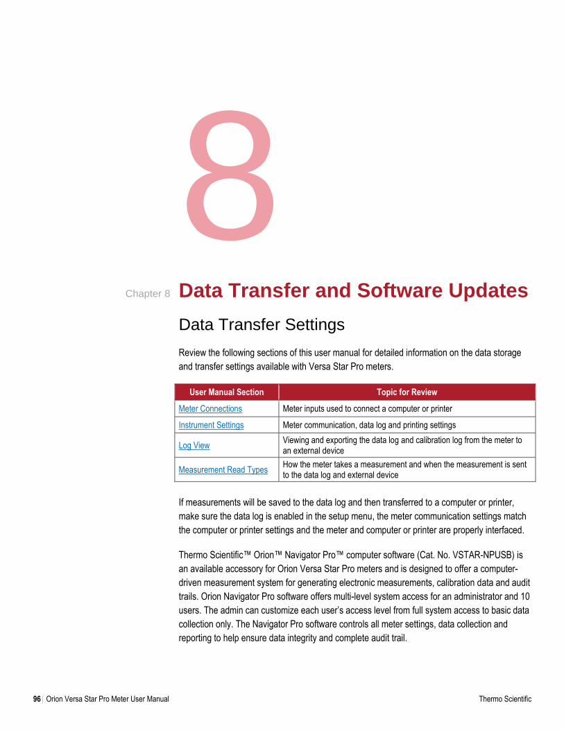
96 Orion Versa Star Pro Meter User Manual Thermo Scientific
8 Data Transfer and Software Updates
Data Transfer Settings
Review the following sections of this user manual for detailed information on the data storage
and transfer settings available with Versa Star Pro meters.
User Manual Section Topic for Review
Meter Connections Meter inputs used to connect a computer or printer
Instrument Settings Meter communication, data log and printing settings
Log View Viewing and exporting the data log and calibration log from the meter to an external device
Measurement Read Types How the meter takes a measurement and when the measurement is sent to the data log and external device
If measurements will be saved to the data log and then transferred to a computer or printer,
make sure the data log is enabled in the setup menu, the meter communication settings match
the computer or printer settings and the meter and computer or printer are properly interfaced.
Thermo Scientific™ Orion™ Navigator Pro™ computer software (Cat. No. VSTAR-NPUSB) is
an available accessory for Orion Versa Star Pro meters and is designed to offer a computer-
driven measurement system for generating electronic measurements, calibration data and audit
trails. Orion Navigator Pro software offers multi-level system access for an administrator and 10
users. The admin can customize each user’s access level from full system access to basic data
collection only. The Navigator Pro software controls all meter settings, data collection and
reporting to help ensure data integrity and complete audit trail.
Chapter 8
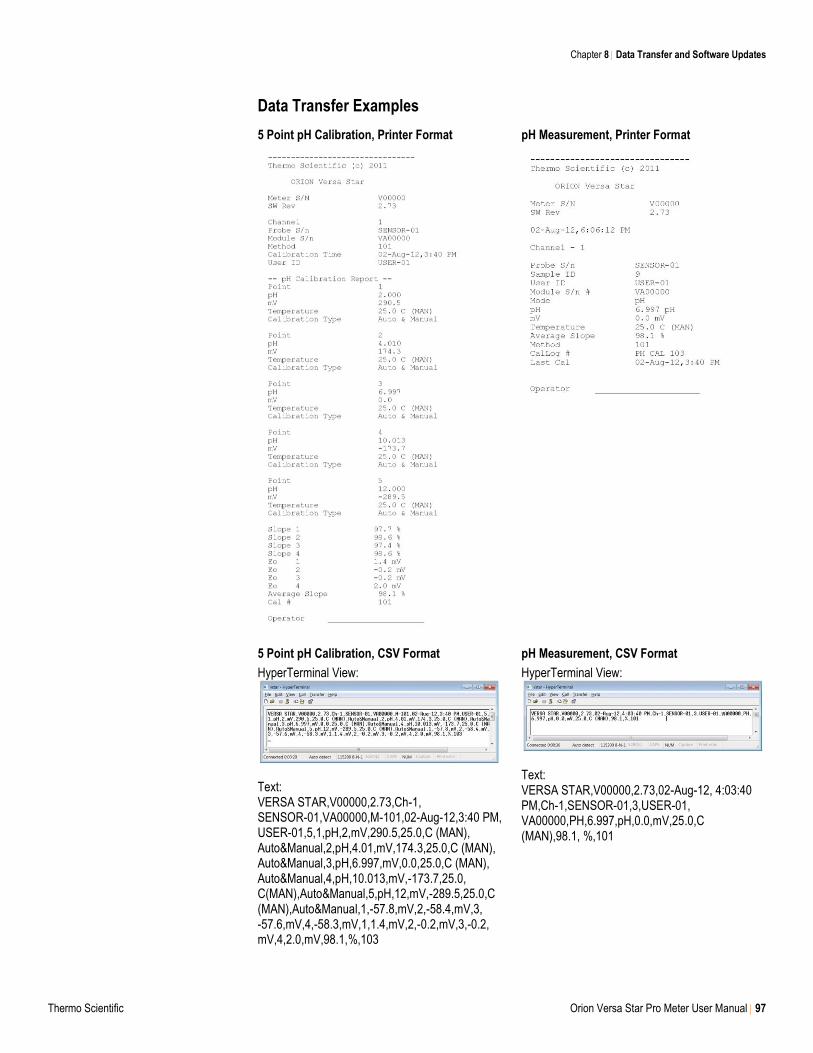
Chapter 8 Data Transfer and Software Updates
Thermo Scientific Orion Versa Star Pro Meter User Manual 97
Data Transfer Examples
5 Point pH Calibration, Printer Format
pH Measurement, Printer Format
5 Point pH Calibration, CSV Format
HyperTerminal View:
Text: VERSA STAR,V00000,2.73,Ch-1, SENSOR-01,VA00000,M-101,02-Aug-12,3:40 PM, USER-01,5,1,pH,2,mV,290.5,25.0,C (MAN), Auto&Manual,2,pH,4.01,mV,174.3,25.0,C (MAN), Auto&Manual,3,pH,6.997,mV,0.0,25.0,C (MAN), Auto&Manual,4,pH,10.013,mV,-173.7,25.0, C(MAN),Auto&Manual,5,pH,12,mV,-289.5,25.0,C (MAN),Auto&Manual,1,-57.8,mV,2,-58.4,mV,3, -57.6,mV,4,-58.3,mV,1,1.4,mV,2,-0.2,mV,3,-0.2, mV,4,2.0,mV,98.1,%,103
pH Measurement, CSV Format
HyperTerminal View:
Text: VERSA STAR,V00000,2.73,02-Aug-12, 4:03:40 PM,Ch-1,SENSOR-01,3,USER-01, VA00000,PH,6.997,pH,0.0,mV,25.0,C (MAN),98.1, %,101
Chapter 8 Data Transfer and Software Updates
98 Orion Versa Star Pro Meter User Manual Thermo Scientific
Installing the Versa Star USB Driver Software
Note: Installation of the USB driver is required to transfer data from the Versa Star Pro meter to
a computer via the USB port. The driver is not required to update the meter software.
1. Download the Versa Star Pro meter USB driver file on our website and unzip the file to the
computer’s desktop. The file can also be downloaded from the Versa Star Pro Literature
CD that is included with meter and saved to the computer desktop.
2. Connect the power adapter to the meter and power on the meter.
3. Connect the USB cable to Mini B USB input on the meter and USB input on a computer.
4. The Found New Hardware Wizard window will open. Select “No, not this time” and click the
Next button.
a. If the meter does not give a popup message, go to the Device Manager, expand the
Ports or Other Devices option and double-click the IAR file.
5. Select “Install from a list or specific location (Advanced)” and click the Next button.
6. Select “Search for the best driver in these locations” and check the box next to the “Include
this location in the search:” option. Click the Browse button and set the computer desktop
as the location. Click the Next button.
7. Wait while the driver is loaded and accept any warning messages. Once the installation is
complete, click the Finish button
8. Set the Versa Star Pro meter setup parameters to allow transferring data from the meter to
the computer via the USB drive.
a. On the meter in the measurement mode, press the setup key.
b. Press the or key to highlight Instrument Settings and press the f3 (Select) key.
c. Press the or key highlight Communication and press the or key to highlight
USB.
d. Press the f2 (Page 2) key.
e. Press the or key to highlight Printing and press the or key to highlight On.
f. Press the or key to highlight Print Format and press the or key to highlight
CSV (comma delimited text) or Printer (standard text).
g. Press the measure (esc) key to return to the measurement mode.
9. Review the computer COM port location and settings in the Device Manager.
a. Expand the Ports option and double click the “IAR Virtual COM port” option.
b. The Property window for the IAR Virtual COM port will open. Select the Port Settings
tab and make sure the communication settings are: Bits per second: 115200; Data bits:
8; Parity: None; Stop bits: 1; Flow control: None
10. The meter is now able to transfer data to the computer using the virtual COM port and
HyperTerminal or similar program.
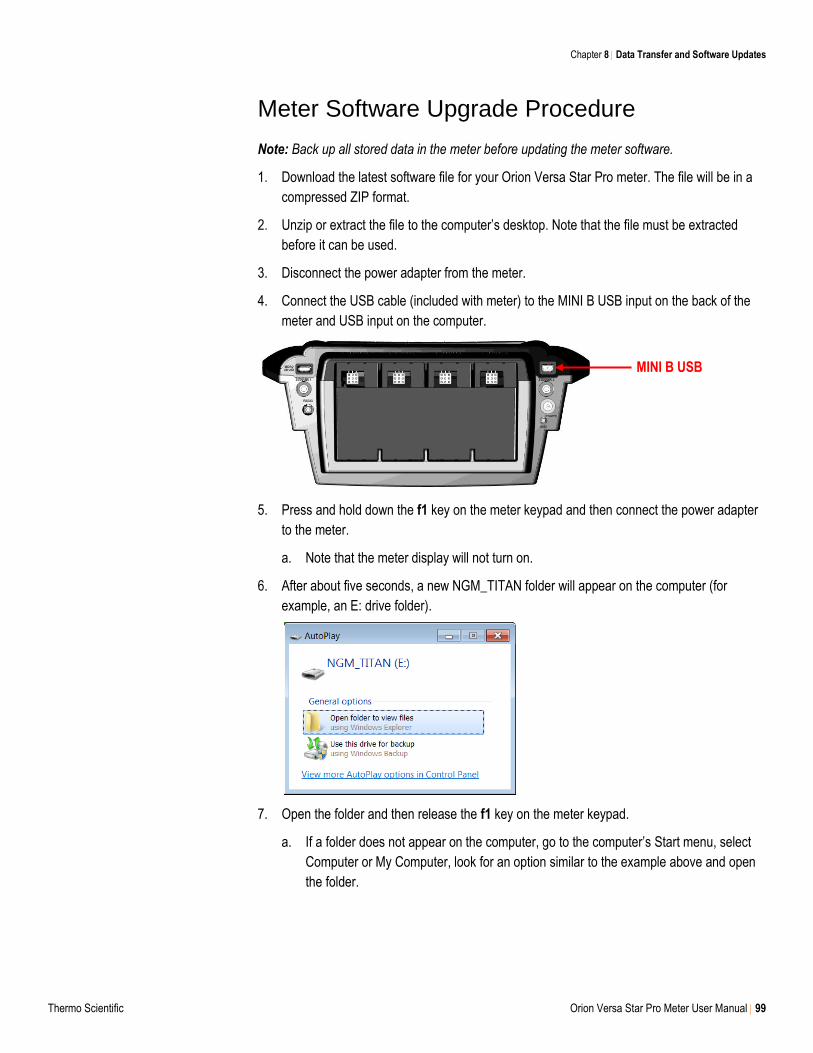
Chapter 8 Data Transfer and Software Updates
Thermo Scientific Orion Versa Star Pro Meter User Manual 99
Meter Software Upgrade Procedure
Note: Back up all stored data in the meter before updating the meter software.
1. Download the latest software file for your Orion Versa Star Pro meter. The file will be in a
compressed ZIP format.
2. Unzip or extract the file to the computer’s desktop. Note that the file must be extracted
before it can be used.
3. Disconnect the power adapter from the meter.
4. Connect the USB cable (included with meter) to the MINI B USB input on the back of the
meter and USB input on the computer.
5. Press and hold down the f1 key on the meter keypad and then connect the power adapter
to the meter.
a. Note that the meter display will not turn on.
6. After about five seconds, a new NGM_TITAN folder will appear on the computer (for
example, an E: drive folder).
7. Open the folder and then release the f1 key on the meter keypad.
a. If a folder does not appear on the computer, go to the computer’s Start menu, select
Computer or My Computer, look for an option similar to the example above and open
the folder.
MINI B USB
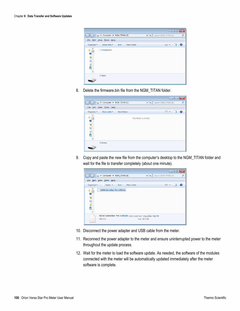
Chapter 8 Data Transfer and Software Updates
100 Orion Versa Star Pro Meter User Manual Thermo Scientific
8. Delete the firmware.bin file from the NGM_TITAN folder.
9. Copy and paste the new file from the computer’s desktop to the NGM_TITAN folder and
wait for the file to transfer completely (about one minute).
10. Disconnect the power adapter and USB cable from the meter.
11. Reconnect the power adapter to the meter and ensure uninterrupted power to the meter
throughout the update process.
12. Wait for the meter to load the software update. As needed, the software of the modules
connected with the meter will be automatically updated immediately after the meter
software is complete.
Chapter 8 Data Transfer and Software Updates
Thermo Scientific Orion Versa Star Pro Meter User Manual 101
Computer and Printer Compatibility
Computer Requirements
The Versa Star USB driver and software update program have been tested with Microsoft®
Windows® XP, Windows Vista® and Windows 7 operating systems. We are always working to
update our programs, so please contact our technical support team for the latest Windows
compatibility updates.
The computer must be up-to-date with the latest Windows updates installed and have .NET
framework version 4.0 with the latest updates.
It is strongly recommended that all computer screen savers and power management settings be
disabled when the meter is interfaced with the computer. The computer must not go into
sleep/standby mode while the software update is performed. Many laptop computers go into
sleep/standby mode when the lid is closed, so the lid should remain open throughout the
software update. Laptop computers must also be plugged into a power supply when running the
software update – performing the software update while the computer is on battery power is not
recommended.
Printer Requirements
Versa Star Pro meters can print directly to the Orion Star A series compact ink ribbon printer
(Catalog Number STARA-106) or certain models of USB dedicated printers with PCL 5 or PCL
6 printer language capability.
Orion Versa Star Pro meters offer expanded USB printer compatibility with new PCL 6 driver
hardware for better compatibility with recent, commercially available USB printers. Although we
strive to ensure the compatibility of our meters with USB printers, we cannot ensure
compatibility with all models.
Tested Printer Models:
Fuji Xerox DocuPrint P225D
HP LaserJet Pro MFP M225DW
Printer Component and Requirements
Meter: Orion Versa Star Pro meter, serial number V10000 or higher
Printer: PCL6 driver compatible
Paper: Letter size format
Cable: Micro AB USB Male (meter) to printer-specific USB connection (per printer model)
For the tested printer models, the printer cable requirement is Micro AB USB Male to Standard
USB B Type cable.
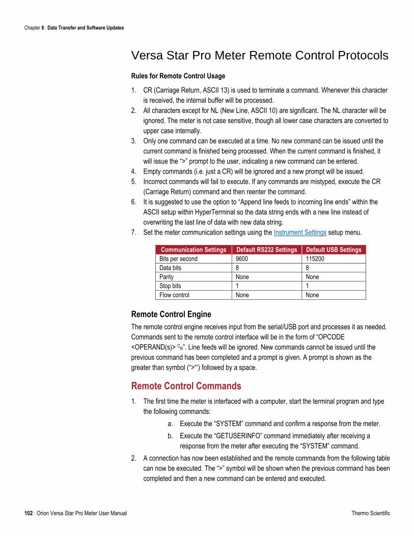
Chapter 8 Data Transfer and Software Updates
102 Orion Versa Star Pro Meter User Manual Thermo Scientific
Versa Star Pro Meter Remote Control Protocols
Rules for Remote Control Usage
1. CR (Carriage Return, ASCII 13) is used to terminate a command. Whenever this character
is received, the internal buffer will be processed.
2. All characters except for NL (New Line, ASCII 10) are significant. The NL character will be
ignored. The meter is not case sensitive, though all lower case characters are converted to
upper case internally.
3. Only one command can be executed at a time. No new command can be issued until the
current command is finished being processed. When the current command is finished, it
will issue the “>” prompt to the user, indicating a new command can be entered.
4. Empty commands (i.e. just a CR) will be ignored and a new prompt will be issued.
5. Incorrect commands will fail to execute. If any commands are mistyped, execute the CR
(Carriage Return) command and then reenter the command.
6. It is suggested to use the option to “Append line feeds to incoming line ends” within the
ASCII setup within HyperTerminal so the data string ends with a new line instead of
overwriting the last line of data with new data string.
7. Set the meter communication settings using the Instrument Settings setup menu.
Communication Settings Default RS232 Settings Default USB Settings
Bits per second 9600 115200
Data bits 8 8
Parity None None
Stop bits 1 1
Flow control None None
Remote Control Engine
The remote control engine receives input from the serial/USB port and processes it as needed.
Commands sent to the remote control interface will be in the form of “OPCODE
<OPERAND(s)> CR”. Line feeds will be ignored. New commands cannot be issued until the
previous command has been completed and a prompt is given. A prompt is shown as the
greater than symbol (“>“‘) followed by a space.
Remote Control Commands
1. The first time the meter is interfaced with a computer, start the terminal program and type
the following commands:
a. Execute the “SYSTEM” command and confirm a response from the meter.
b. Execute the “GETUSERINFO” command immediately after receiving a
response from the meter after executing the “SYSTEM” command.
2. A connection has now been established and the remote commands from the following table
can now be executed. The “>” symbol will be shown when the previous command has been
completed and then a new command can be entered and executed.
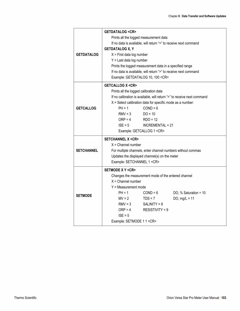
Chapter 8 Data Transfer and Software Updates
Thermo Scientific Orion Versa Star Pro Meter User Manual 103
GETDATALOG
GETDATALOG <CR>
Prints all the logged measurement data
If no data is available, will return “>” to receive next command
GETDATALOG X, Y
X = First data log number
Y = Last data log number
Prints the logged measurement data in a specified range
If no data is available, will return “>” to receive next command
Example: GETDATALOG 10, 100 <CR>
GETCALLOG
GETCALLOG X <CR>
Prints all the logged calibration data
If no calibration is available, will return “>” to receive next command
X = Select calibration data for specific mode as a number:
PH = 1 COND = 6
RMV = 3 DO = 10
ORP = 4 RDO = 12
ISE = 5 INCREMENTAL = 21
Example: GETCALLOG 1 <CR>
SETCHANNEL
SETCHANNEL X <CR>
X = Channel number
For multiple channels, enter channel numbers without commas
Updates the displayed channel(s) on the meter
Example: SETCHANNEL 1 <CR>
SETMODE
SETMODE X Y <CR>
Changes the measurement mode of the entered channel
X = Channel number
Y = Measurement mode
PH = 1 COND = 6 DO, % Saturation = 10
MV = 2 TDS = 7 DO, mg/L = 11
RMV = 3 SALINITY = 8
ORP = 4 RESISTIVITY = 9
ISE = 5
Example: SETMODE 1 1 <CR>
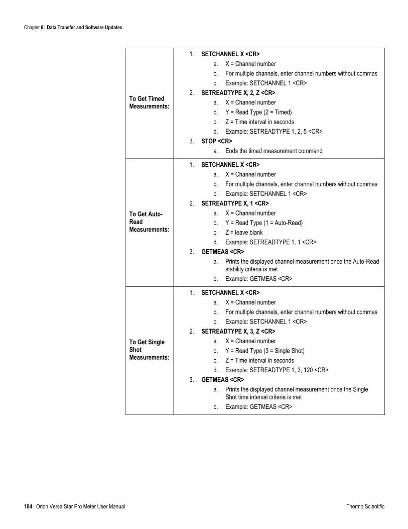
Chapter 8 Data Transfer and Software Updates
104 Orion Versa Star Pro Meter User Manual Thermo Scientific
To Get Timed Measurements:
1. SETCHANNEL X <CR>
a. X = Channel number
b. For multiple channels, enter channel numbers without commas
c. Example: SETCHANNEL 1 <CR>
2. SETREADTYPE X, 2, Z <CR>
a. X = Channel number
b. Y = Read Type (2 = Timed)
c. Z = Time interval in seconds
d. Example: SETREADTYPE 1, 2, 5 <CR>
3. STOP <CR>
a. Ends the timed measurement command
To Get Auto-Read Measurements:
1. SETCHANNEL X <CR>
a. X = Channel number
b. For multiple channels, enter channel numbers without commas
c. Example: SETCHANNEL 1 <CR>
2. SETREADTYPE X, 1 <CR>
a. X = Channel number
b. Y = Read Type (1 = Auto-Read)
c. Z = leave blank
d. Example: SETREADTYPE 1, 1 <CR>
3. GETMEAS <CR>
a. Prints the displayed channel measurement once the Auto-Read stability criteria is met
b. Example: GETMEAS <CR>
To Get Single Shot Measurements:
1. SETCHANNEL X <CR>
a. X = Channel number
b. For multiple channels, enter channel numbers without commas
c. Example: SETCHANNEL 1 <CR>
2. SETREADTYPE X, 3, Z <CR>
a. X = Channel number
b. Y = Read Type (3 = Single Shot)
c. Z = Time interval in seconds
d. Example: SETREADTYPE 1, 3, 120 <CR>
3. GETMEAS <CR>
a. Prints the displayed channel measurement once the Single Shot time interval criteria is met
b. Example: GETMEAS <CR>
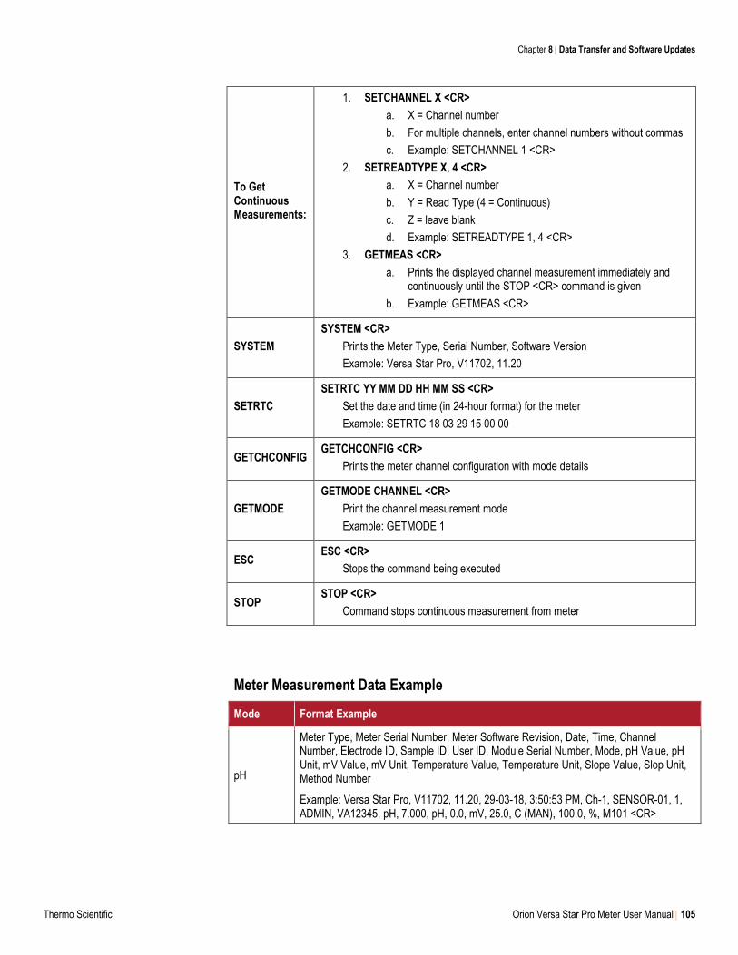
Chapter 8 Data Transfer and Software Updates
Thermo Scientific Orion Versa Star Pro Meter User Manual 105
To Get Continuous Measurements:
1. SETCHANNEL X <CR>
a. X = Channel number
b. For multiple channels, enter channel numbers without commas
c. Example: SETCHANNEL 1 <CR>
2. SETREADTYPE X, 4 <CR>
a. X = Channel number
b. Y = Read Type (4 = Continuous)
c. Z = leave blank
d. Example: SETREADTYPE 1, 4 <CR>
3. GETMEAS <CR>
a. Prints the displayed channel measurement immediately and continuously until the STOP <CR> command is given
b. Example: GETMEAS <CR>
SYSTEM
SYSTEM <CR>
Prints the Meter Type, Serial Number, Software Version
Example: Versa Star Pro, V11702, 11.20
SETRTC
SETRTC YY MM DD HH MM SS <CR>
Set the date and time (in 24-hour format) for the meter
Example: SETRTC 18 03 29 15 00 00
GETCHCONFIG GETCHCONFIG <CR>
Prints the meter channel configuration with mode details
GETMODE
GETMODE CHANNEL <CR>
Print the channel measurement mode
Example: GETMODE 1
ESC ESC <CR>
Stops the command being executed
STOP STOP <CR>
Command stops continuous measurement from meter
Meter Measurement Data Example
Mode Format Example
pH
Meter Type, Meter Serial Number, Meter Software Revision, Date, Time, Channel Number, Electrode ID, Sample ID, User ID, Module Serial Number, Mode, pH Value, pH Unit, mV Value, mV Unit, Temperature Value, Temperature Unit, Slope Value, Slop Unit, Method Number
Example: Versa Star Pro, V11702, 11.20, 29-03-18, 3:50:53 PM, Ch-1, SENSOR-01, 1, ADMIN, VA12345, pH, 7.000, pH, 0.0, mV, 25.0, C (MAN), 100.0, %, M101 <CR>
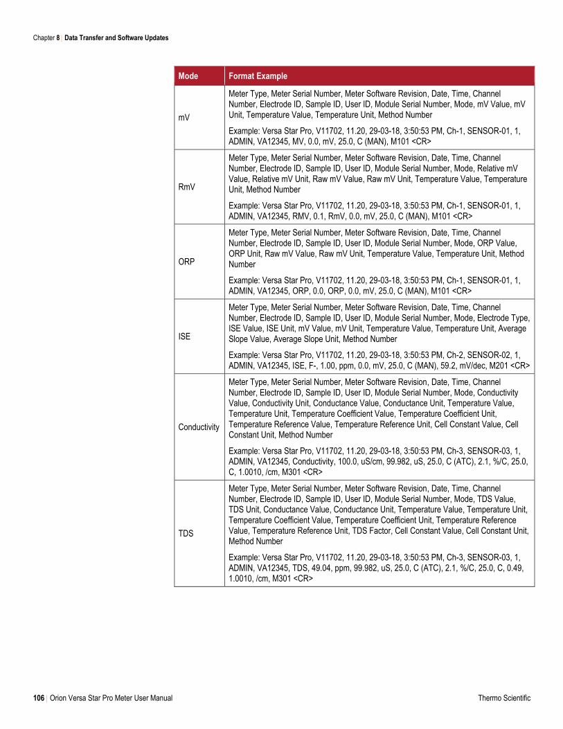
Chapter 8 Data Transfer and Software Updates
106 Orion Versa Star Pro Meter User Manual Thermo Scientific
Mode Format Example
mV
Meter Type, Meter Serial Number, Meter Software Revision, Date, Time, Channel Number, Electrode ID, Sample ID, User ID, Module Serial Number, Mode, mV Value, mV Unit, Temperature Value, Temperature Unit, Method Number
Example: Versa Star Pro, V11702, 11.20, 29-03-18, 3:50:53 PM, Ch-1, SENSOR-01, 1, ADMIN, VA12345, MV, 0.0, mV, 25.0, C (MAN), M101 <CR>
RmV
Meter Type, Meter Serial Number, Meter Software Revision, Date, Time, Channel Number, Electrode ID, Sample ID, User ID, Module Serial Number, Mode, Relative mV Value, Relative mV Unit, Raw mV Value, Raw mV Unit, Temperature Value, Temperature Unit, Method Number
Example: Versa Star Pro, V11702, 11.20, 29-03-18, 3:50:53 PM, Ch-1, SENSOR-01, 1, ADMIN, VA12345, RMV, 0.1, RmV, 0.0, mV, 25.0, C (MAN), M101 <CR>
ORP
Meter Type, Meter Serial Number, Meter Software Revision, Date, Time, Channel Number, Electrode ID, Sample ID, User ID, Module Serial Number, Mode, ORP Value, ORP Unit, Raw mV Value, Raw mV Unit, Temperature Value, Temperature Unit, Method Number
Example: Versa Star Pro, V11702, 11.20, 29-03-18, 3:50:53 PM, Ch-1, SENSOR-01, 1, ADMIN, VA12345, ORP, 0.0, ORP, 0.0, mV, 25.0, C (MAN), M101 <CR>
ISE
Meter Type, Meter Serial Number, Meter Software Revision, Date, Time, Channel Number, Electrode ID, Sample ID, User ID, Module Serial Number, Mode, Electrode Type, ISE Value, ISE Unit, mV Value, mV Unit, Temperature Value, Temperature Unit, Average Slope Value, Average Slope Unit, Method Number
Example: Versa Star Pro, V11702, 11.20, 29-03-18, 3:50:53 PM, Ch-2, SENSOR-02, 1, ADMIN, VA12345, ISE, F-, 1.00, ppm, 0.0, mV, 25.0, C (MAN), 59.2, mV/dec, M201 <CR>
Conductivity
Meter Type, Meter Serial Number, Meter Software Revision, Date, Time, Channel Number, Electrode ID, Sample ID, User ID, Module Serial Number, Mode, Conductivity Value, Conductivity Unit, Conductance Value, Conductance Unit, Temperature Value, Temperature Unit, Temperature Coefficient Value, Temperature Coefficient Unit, Temperature Reference Value, Temperature Reference Unit, Cell Constant Value, Cell Constant Unit, Method Number
Example: Versa Star Pro, V11702, 11.20, 29-03-18, 3:50:53 PM, Ch-3, SENSOR-03, 1, ADMIN, VA12345, Conductivity, 100.0, uS/cm, 99.982, uS, 25.0, C (ATC), 2.1, %/C, 25.0, C, 1.0010, /cm, M301 <CR>
TDS
Meter Type, Meter Serial Number, Meter Software Revision, Date, Time, Channel Number, Electrode ID, Sample ID, User ID, Module Serial Number, Mode, TDS Value, TDS Unit, Conductance Value, Conductance Unit, Temperature Value, Temperature Unit, Temperature Coefficient Value, Temperature Coefficient Unit, Temperature Reference Value, Temperature Reference Unit, TDS Factor, Cell Constant Value, Cell Constant Unit, Method Number
Example: Versa Star Pro, V11702, 11.20, 29-03-18, 3:50:53 PM, Ch-3, SENSOR-03, 1, ADMIN, VA12345, TDS, 49.04, ppm, 99.982, uS, 25.0, C (ATC), 2.1, %/C, 25.0, C, 0.49, 1.0010, /cm, M301 <CR>
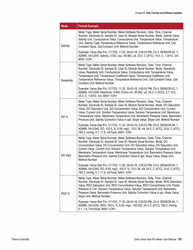
Chapter 8 Data Transfer and Software Updates
Thermo Scientific Orion Versa Star Pro Meter User Manual 107
Mode Format Example
Salinity
Meter Type, Meter Serial Number, Meter Software Revision, Date, Time, Channel Number, Electrode ID, Sample ID, User ID, Module Serial Number, Mode, Salinity Value, Salinity Unit, Conductance Value, Conductance Unit, Temperature Value, Temperature Unit, Salinity Type, Temperature Reference Value, Temperature Reference Unit, Cell Constant Value, Cell Constant Unit, Method Number
Example: Versa Star Pro, V11702, 11.20, 29-03-18, 3:50:53 PM, Ch-3, SENSOR-03, 1, ADMIN, VA12345, Salinity, 0.052, psu, 99.982, uS, 25.0, C (ATC), 15.0, C, 1.0010, /cm, M301 <CR>
Resistivity
Meter Type, Meter Serial Number, Meter Software Revision, Date, Time, Channel Number, Electrode ID, Sample ID, User ID, Module Serial Number, Mode, Resistivity Value, Resistivity Unit, Conductance Value, Conductance Unit, Temperature Value, Temperature Unit, Temperature Coefficient Value, Temperature Coefficient Unit, Temperature Reference Value, Temperature Reference Unit, Cell Constant Value, Cell Constant Unit, Method Number
Example: Versa Star Pro, V11702, 11.20, 29-03-18, 3:50:53 PM, Ch-3, SENSOR-03, 1, ADMIN, VA12345, Resistivity, 9.992, KOhm-cm, 99.982, uS, 25.0, C (ATC), 2.1, %/C, 25.0, C, 1.0010, /cm, M301 <CR>
DO %
Meter Type, Meter Serial Number, Meter Software Revision, Date, Time, Channel Number, Electrode ID, Sample ID, User ID, Module Serial Number, Mode, DO Saturation Value, DO Saturation Unit, DO Concentration Value, DO Concentration Unit, Current Value, Current Unit, Solution Temperature Value, Solution Temperature Unit, Membrane Temperature Value, Membrane Temperature Unit, Barometric Pressure Value, Barometric Pressure Unit, Salinity Correction Value in ppt, Slope Value, Slope Unit, Method Number
Example: Versa Star Pro, V11702, 11.20, 29-03-18, 3:50:53 PM, Ch-4, SENSOR-04, 1, ADMIN, VA12345, DO, 102.0, %, 8.59, mg/L, 1331.38, nA, 24.5, C (ATC), 24.6, C (ATC), 760.2, mmHg, 0.1, 11.8, nA/%sat, M401 <CR>
DO mg/L
Meter Type, Meter Serial Number, Meter Software Revision, Date, Time, Channel Number, Electrode ID, Sample ID, User ID, Module Serial Number, Mode, DO Concentration Value, DO Concentration Unit, DO Saturation Value, DO Saturation Unit, Current Value, Current Unit, Solution Temperature Value, Solution Temperature Unit, Membrane Temperature Value, Membrane Temperature Unit, Barometric Pressure Value, Barometric Pressure Unit, Salinity Correction Value in ppt, Slope Value, Slope Unit, Method Number
Example: Versa Star Pro, V11702, 11.20, 29-03-18, 3:50:53 PM, Ch-4, SENSOR-04, 1, ADMIN, VA12345, DO, 8.59, mg/L, 102.0, %, 1331.38, nA, 24.5, C (ATC), 24.6, C (ATC), 760.2, mmHg, 0.1, 11.8, nA/%sat, M401 <CR>
RDO %
Meter Type, Meter Serial Number, Meter Software Revision, Date, Time, Channel Number, Electrode ID, Sample ID, User ID, Module Serial Number, Mode, RDO Saturation Value, RDO Saturation Unit, RDO Concentration Value, RDO Concentration Unit, Partial Pressure in Torr, Solution Temperature Value, Solution Temperature Unit, Barometric Pressure Value, Barometric Pressure Unit, Salinity Correction Value in ppt, Slope Value, Slope Unit, Method Number
Example: Versa Star Pro, V11702, 11.20, 29-03-18, 3:50:53 PM, Ch-4, SENSOR-04, 1, ADMIN, VA12345, RDO, 102.0, %, 8.59, mg/L, 150.052, 24.3, C (ATC), 760.2, mmHg, 0.1, 1.6, Torr/%Sat, M401 <CR>
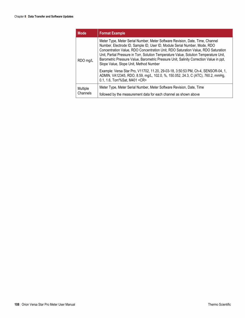
Chapter 8 Data Transfer and Software Updates
108 Orion Versa Star Pro Meter User Manual Thermo Scientific
Mode Format Example
RDO mg/L
Meter Type, Meter Serial Number, Meter Software Revision, Date, Time, Channel Number, Electrode ID, Sample ID, User ID, Module Serial Number, Mode, RDO Concentration Value, RDO Concentration Unit, RDO Saturation Value, RDO Saturation Unit, Partial Pressure in Torr, Solution Temperature Value, Solution Temperature Unit, Barometric Pressure Value, Barometric Pressure Unit, Salinity Correction Value in ppt, Slope Value, Slope Unit, Method Number
Example: Versa Star Pro, V11702, 11.20, 29-03-18, 3:50:53 PM, Ch-4, SENSOR-04, 1, ADMIN, VA12345, RDO, 8.59, mg/L, 102.0, %, 150.052, 24.3, C (ATC), 760.2, mmHg, 0.1, 1.6, Torr/%Sat, M401 <CR>
Multiple Channels
Meter Type, Meter Serial Number, Meter Software Revision, Date, Time
followed by the measurement data for each channel as shown above
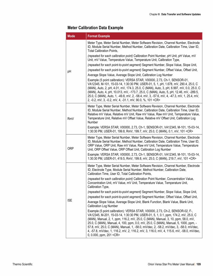
Chapter 8 Data Transfer and Software Updates
Thermo Scientific Orion Versa Star Pro Meter User Manual 109
Meter Calibration Data Example
Mode Format Example
pH
Meter Type, Meter Serial Number, Meter Software Revision, Channel Number, Electrode ID, Module Serial Number, Method Number, Calibration Date, Calibration Time, User ID, Total Calibration Points,
(repeated for each calibration point) Calibration Point Number, pH Unit, pH Value, mV Unit, mV Value, Temperature Value, Temperature Unit, Calibration Type,
(repeated for each point-to-point segment) Segment Number, Slope Value, Slope Unit,
(repeated for each point-to-point segment) Segment Number, Offset Value, Offset Unit,
Average Slope Value, Average Slope Unit, Calibration Log Number
Example (5 point calibration): VERSA STAR, V00000, 2.73, Ch-1, SENSOR-01, VA12345, M-101, 15-03-14, 1:30:30 PM, USER-01, 5, 1, pH, 1.678, mV, 290.4, 25.0, C (MAN), Auto, 2, pH, 4.01, mV, 174.3, 25.0, C (MAN), Auto, 3, pH, 6.997, mV, 0.0, 25.0, C (MAN), Auto, 4, pH, 10.013, mV, -173.7, 25.0, C (MAN), Auto, 5, pH, 12.46, mV, -289.5, 25.0, C (MAN), Auto, 1, -49.8, mV, 2, -58.4, mV, 3, -57.6, mV, 4, -47.3, mV, 1, 25.4, mV, 2, -0.2, mV, 3, -0.2, mV, 4, -31.1, mV, 90.0, %, 101 <CR>
RmV
Meter Type, Meter Serial Number, Meter Software Revision, Channel Number, Electrode ID, Module Serial Number, Method Number, Calibration Date, Calibration Time, User ID, Relative mV Value, Relative mV Unit, Raw mV Value, Raw mV Unit, Temperature Value, Temperature Unit, Relative mV Offset Value, Relative mV Offset Unit, Calibration Log Number
Example: VERSA STAR, V00000, 2.73, Ch-1, SENSOR-01, VA12345, M-101, 15-03-14, 1:30:30 PM, USER-01, 199.8, RmV, 199.7, mV, 25.0, C (MAN), 0.1, mV, 101 <CR>
ORP
Meter Type, Meter Serial Number, Meter Software Revision, Channel Number, Electrode ID, Module Serial Number, Method Number, Calibration Date, Calibration Time, User ID, ORP Value, ORP Unit, Raw mV Value, Raw mV Unit, Temperature Value, Temperature Unit, ORP Offset Value, ORP Offset Unit, Calibration Log Number
Example: VERSA STAR, V00000, 2.73, Ch-1, SENSOR-01, VA12345, M-101, 15-03-14, 1:30:30 PM, USER-01, 419.5, RmV, 199.8, mV, 25.0, C (MAN), 219.7, mV, 101 <CR>
ISE
Meter Type, Meter Serial Number, Meter Software Revision, Channel Number, Electrode ID, Electrode Type, Module Serial Number, Method Number, Calibration Date, Calibration Time, User ID, Total Calibration Points,
(repeated for each calibration point) Calibration Point Number, Concentration Value, Concentration Unit, mV Value, mV Unit, Temperature Value, Temperature Unit, Calibration Type,
(repeated for each point-to-point segment) Segment Number, Slope Value, Slope Unit,
(repeated for each point-to-point segment) Segment Number, Offset Value, Offset Unit,
Average Slope Value, Average Slope Unit, Blank Function, Blank Value, Blank Unit, Calibration Log Number
Example (5 point calibration): VERSA STAR, V00000, 2.73, Ch-2, SENSOR-02, F-, VA12345, M-201, 15-03-14, 1:30:30 PM, USER-01, 5, 1, 0.1, ppm, 174.2, mV, 25.0, C (MAN), Manual, 2, 1, ppm, 116.2, mV, 25.0, C (MAN), Manual, 3, 10, ppm, 58.0, mV, 25.0, C (MAN), Manual, 4, 100, ppm, 0.0, mV, 25.0, C (MAN), Manual, 5, 1000, ppm, -57.8, mV, 25.0, C (MAN), Manual, 1, -58.0, mV/dec, 2, -58.2, mV/dec, 3, -58.0, mV/dec, 4, -57.8, mV/dec, 1, 116.2, mV, 2, 116.2, mV, 3, 116.0, mV, 4, 115.6, mV, -58.0, mV/dec, 0, 0.000, ppm, 201 <CR>
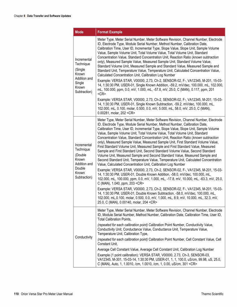
Chapter 8 Data Transfer and Software Updates
110 Orion Versa Star Pro Meter User Manual Thermo Scientific
Mode Format Example
Incremental Technique
(Single Known Addition and Single Known Subtraction)
Meter Type, Meter Serial Number, Meter Software Revision, Channel Number, Electrode ID, Electrode Type, Module Serial Number, Method Number, Calibration Date, Calibration Time, User ID, Incremental Type, Slope Value, Slope Unit, Sample Volume Value, Sample Volume Unit, Total Volume Value, Total Volume Unit, Standard Concentration Value, Standard Concentration Unit, Reaction Ratio (known subtraction only), Measured Sample Value, Measured Sample Unit, Standard Volume Value, Standard Volume Unit, Measured Sample and Standard Value, Measured Sample and Standard Unit, Temperature Value, Temperature Unit, Calculated Concentration Value, Calculated Concentration Unit, Calibration Log Number
Example: VERSA STAR, V00000, 2.73, Ch-2, SENSOR-02, F-, VA12345, M-201, 15-03-14, 1:30:30 PM, USER-01, Single Known Addition, -59.2, mV/dec, 100.000, mL, 102.000, mL, 100.000, ppm, 0.0, mV, 1.000, mL, -57.8, mV, 25.0, C (MAN), 0.117, ppm, 201 <CR>
Example: VERSA STAR, V00000, 2.73, Ch-2, SENSOR-02, F-, VA12345, M-201, 15-03-14, 1:30:30 PM, USER-01, Single Known Subtraction, -59.2, mV/dec, 100.000, mL, 102.000, mL, 0.100, molar, 0.500, 0.0, mV, 5.000, mL, 58.0, mV, 25.0, C (MAN), 0.00281, molar, 202 <CR>
Incremental Technique
(Double Known Addition and Double Known Subtraction)
Meter Type, Meter Serial Number, Meter Software Revision, Channel Number, Electrode ID, Electrode Type, Module Serial Number, Method Number, Calibration Date, Calibration Time, User ID, Incremental Type, Slope Value, Slope Unit, Sample Volume Value, Sample Volume Unit, Total Volume Value, Total Volume Unit, Standard Concentration Value, Standard Concentration Unit, Reaction Ratio (known subtraction only), Measured Sample Value, Measured Sample Unit, First Standard Volume Value, First Standard Volume Unit, Measured Sample and First Standard Value, Measured Sample and First Standard Unit, Second Standard Volume Value, Second Standard Volume Unit, Measured Sample and Second Standard Value, Measured Sample and Second Standard Unit, Temperature Value, Temperature Unit, Calculated Concentration Value, Calculated Concentration Unit, Calibration Log Number
Example: VERSA STAR, V00000, 2.73, Ch-2, SENSOR-02, F-, VA12345, M-201, 15-03-14, 1:30:30 PM, USER-01, Double Known Addition, -58.0, mV/dec, 100.000, mL, 102.000, mL, 100.000, ppm, 0.0, mV, 1.000, mL, -17.8, mV, 10.000, mL, -63.3, mV, 25.0, C (MAN), 1.040, ppm, 203 <CR>
Example: VERSA STAR, V00000, 2.73, Ch-2, SENSOR-02, F-, VA12345, M-201, 15-03-14, 1:30:30 PM, USER-01, Double Known Subtraction, -58.0, mV/dec, 100.000, mL, 102.000, mL,0.100, molar, 0.500, 0.0, mV, 1.000, mL, 8.9, mV, 10.000, mL, 32.3, mV, 25.0, C (MAN), 0.00140, molar, 204 <CR>
Conductivity
Meter Type, Meter Serial Number, Meter Software Revision, Channel Number, Electrode ID, Module Serial Number, Method Number, Calibration Date, Calibration Time, User ID, Total Calibration Points,
(repeated for each calibration point) Calibration Point Number, Conductivity Value, Conductivity Unit, Conductance Value, Conductance Unit, Temperature Value, Temperature Unit, Calibration Type,
(repeated for each calibration point) Calibration Point Number, Cell Constant Value, Cell Constant Unit,
Average Cell Constant Value, Average Cell Constant Unit, Calibration Log Number
Example (1 point calibration): VERSA STAR, V00000, 2.73, Ch-3, SENSOR-03, VA12345, M-301, 15-03-14, 1:30:30 PM, USER-01, 1, 1, 100.0, uS/cm, 99.98, uS, 25.0, C (MAN), Auto, 1, 1.0010, /cm, 1.0010, /cm, 1, 0.00, uS/cm, 301 <CR>
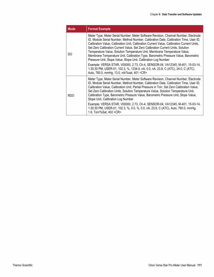
Chapter 8 Data Transfer and Software Updates
Thermo Scientific Orion Versa Star Pro Meter User Manual 111
Mode Format Example
DO
Meter Type, Meter Serial Number, Meter Software Revision, Channel Number, Electrode ID, Module Serial Number, Method Number, Calibration Date, Calibration Time, User ID, Calibration Value, Calibration Unit, Calibration Current Value, Calibration Current Units, Set Zero Calibration Current Value, Set Zero Calibration Current Units, Solution Temperature Value, Solution Temperature Unit, Membrane Temperature Value, Membrane Temperature Unit, Calibration Type, Barometric Pressure Value, Barometric Pressure Unit, Slope Value, Slope Unit, Calibration Log Number
Example: VERSA STAR, V00000, 2.73, Ch-4, SENSOR-04, VA12345, M-401, 15-03-14, 1:30:30 PM, USER-01, 102.3, %, 1334.9, nA, 0.0, nA, 23.8, C (ATC), 24.0, C (ATC), Auto, 760.0, mmHg, 13.0, nA/%sat, 401 <CR>
RDO
Meter Type, Meter Serial Number, Meter Software Revision, Channel Number, Electrode ID, Module Serial Number, Method Number, Calibration Date, Calibration Time, User ID, Calibration Value, Calibration Unit, Partial Pressure in Torr, Set Zero Calibration Value, Set Zero Calibration Units, Solution Temperature Value, Solution Temperature Unit, Calibration Type, Barometric Pressure Value, Barometric Pressure Unit, Slope Value, Slope Unit, Calibration Log Number
Example: VERSA STAR, V00000, 2.73, Ch-4, SENSOR-04, VA12345, M-401, 15-03-14, 1:30:30 PM, USER-01, 102.3, %, 0.0, %, 0.0, nA, 23.8, C (ATC), Auto, 760.0, mmHg, 1.6, Torr/%Sat, 402 <CR>
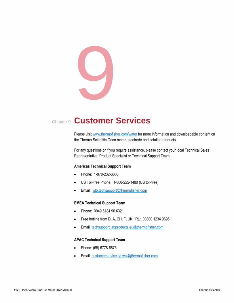
112 Orion Versa Star Pro Meter User Manual Thermo Scientific
9 Customer Services
Please visit www.thermofisher.com/water for more information and downloadable content on
the Thermo Scientific Orion meter, electrode and solution products.
For any questions or if you require assistance, please contact your local Technical Sales
Representative, Product Specialist or Technical Support Team.
Americas Technical Support Team
Phone: 1-978-232-6000
US Toll-free Phone: 1-800-225-1480 (US toll-free)
Email: [email protected]
EMEA Technical Support Team
Phone: 0049 6184 90 6321
Free hotline from D, A, CH, F, UK, IRL: 00800 1234 9696
Email: [email protected]
APAC Technical Support Team
Phone: (65) 6778-6876
Email: [email protected]
Chapter 9
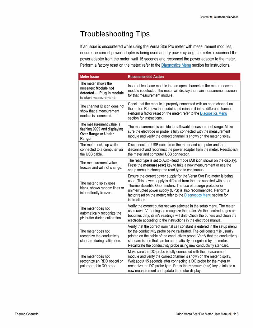
Chapter 9 Customer Services
Thermo Scientific Orion Versa Star Pro Meter User Manual 113
Troubleshooting Tips
If an issue is encountered while using the Versa Star Pro meter with measurement modules,
ensure the correct power adapter is being used and try power cycling the meter: disconnect the
power adapter from the meter, wait 15 seconds and reconnect the power adapter to the meter.
Perform a factory reset on the meter; refer to the Diagnostics Menu section for instructions.
Meter Issue Recommended Action
The meter shows the message: Module not detected … Plug in module to start measurement.
Insert at least one module into an open channel on the meter, once the module is detected, the meter will display the main measurement screen for that measurement module.
The channel ID icon does not show that a measurement module is connected.
Check that the module is properly connected with an open channel on the meter. Remove the module and reinsert it into a different channel. Perform a factor reset on the meter; refer to the Diagnostics Menu section for instructions.
The measurement value is flashing 9999 and displaying Over Range or Under Range
The measurement is outside the allowable measurement range. Make sure the electrode or probe is fully connected with the measurement module and verify the correct channel is shown on the meter display.
The meter locks up while connected to a computer via the USB cable.
Disconnect the USB cable from the meter and computer and then disconnect and reconnect the power adapter from the meter. Reestablish the meter and computer USB connection.
The measurement value freezes and will not change.
The read type is set to Auto-Read mode (AR icon shown on the display). Press the measure (esc) key to take a new measurement or use the setup menu to change the read type to continuous.
The meter display goes blank, shows random lines or intermittently freezes.
Ensure the correct power supply for the Versa Star Pro meter is being used. This power supply is different from the one supplied with other Thermo Scientific Orion meters. The use of a surge protector or uninterrupted power supply (UPS) is also recommended. Perform a factor reset on the meter; refer to the Diagnostics Menu section for instructions.
The meter does not automatically recognize the pH buffer during calibration.
Verify the correct buffer set was selected in the setup menu. The meter uses raw mV readings to recognize the buffer. As the electrode ages or becomes dirty, its mV readings will drift. Check the buffers and clean the electrode according to the instructions in the electrode manual.
The meter does not recognize the conductivity standard during calibration.
Verify that the correct nominal cell constant is entered in the setup menu for the conductivity probe being calibrated. The cell constant is usually printed on the cable of the conductivity probe. Verify that the conductivity standard is one that can be automatically recognized by the meter. Recalibrate the conductivity probe using new conductivity standard.
The meter does not recognize an RDO optical or polarographic DO probe.
Make sure the DO probe is fully connected with the measurement module and verify the correct channel is shown on the meter display. Wait about 15 seconds after connecting a DO probe for the meter to recognize the DO probe type. Press the measure (esc) key to initiate a new measurement and update the meter display.
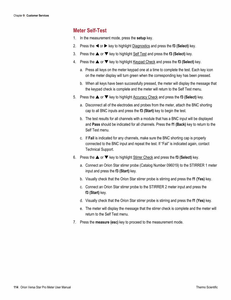
Chapter 9 Customer Services
114 Orion Versa Star Pro Meter User Manual Thermo Scientific
Meter Self-Test
1. In the measurement mode, press the setup key.
2. Press the or key to highlight Diagnostics and press the f3 (Select) key.
3. Press the or key to highlight Self Test and press the f3 (Select) key.
4. Press the or key to highlight Keypad Check and press the f3 (Select) key.
a. Press all keys on the meter keypad one at a time to complete the test. Each key icon
on the meter display will turn green when the corresponding key has been pressed.
b. When all keys have been successfully pressed, the meter will display the message that
the keypad check is complete and the meter will return to the Self Test menu.
5. Press the or key to highlight Accuracy Check and press the f3 (Select) key.
a. Disconnect all of the electrodes and probes from the meter, attach the BNC shorting
cap to all BNC inputs and press the f3 (Start) key to begin the test.
b. The test results for all channels with a module that has a BNC input will be displayed
and Pass should be indicated for all channels. Press the f1 (Back) key to return to the
Self Test menu.
c. If Fail is indicated for any channels, make sure the BNC shorting cap is properly
connected to the BNC input and repeat the test. If “Fail” is indicated again, contact
Technical Support.
6. Press the or key to highlight Stirrer Check and press the f3 (Select) key.
a. Connect an Orion Star stirrer probe (Catalog Number 096019) to the STIRRER 1 meter
input and press the f3 (Start) key.
b. Visually check that the Orion Star stirrer probe is stirring and press the f1 (Yes) key.
c. Connect an Orion Star stirrer probe to the STIRRER 2 meter input and press the
f3 (Start) key.
d. Visually check that the Orion Star stirrer probe is stirring and press the f1 (Yes) key.
e. The meter will display the message that the stirrer check is complete and the meter will
return to the Self Test menu.
7. Press the measure (esc) key to proceed to the measurement mode.
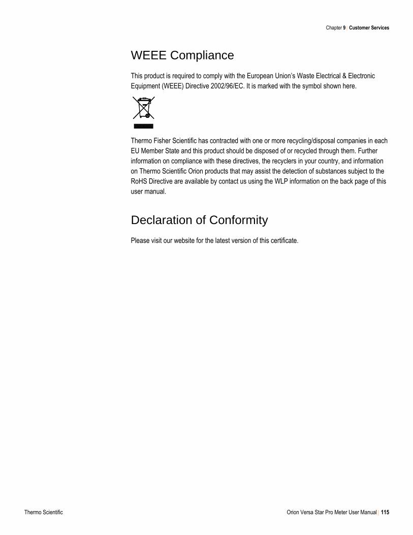
Chapter 9 Customer Services
Thermo Scientific Orion Versa Star Pro Meter User Manual 115
WEEE Compliance
This product is required to comply with the European Union’s Waste Electrical & Electronic
Equipment (WEEE) Directive 2002/96/EC. It is marked with the symbol shown here.
Thermo Fisher Scientific has contracted with one or more recycling/disposal companies in each
EU Member State and this product should be disposed of or recycled through them. Further
information on compliance with these directives, the recyclers in your country, and information
on Thermo Scientific Orion products that may assist the detection of substances subject to the
RoHS Directive are available by contact us using the WLP information on the back page of this
user manual.
Declaration of Conformity
Please visit our website for the latest version of this certificate.
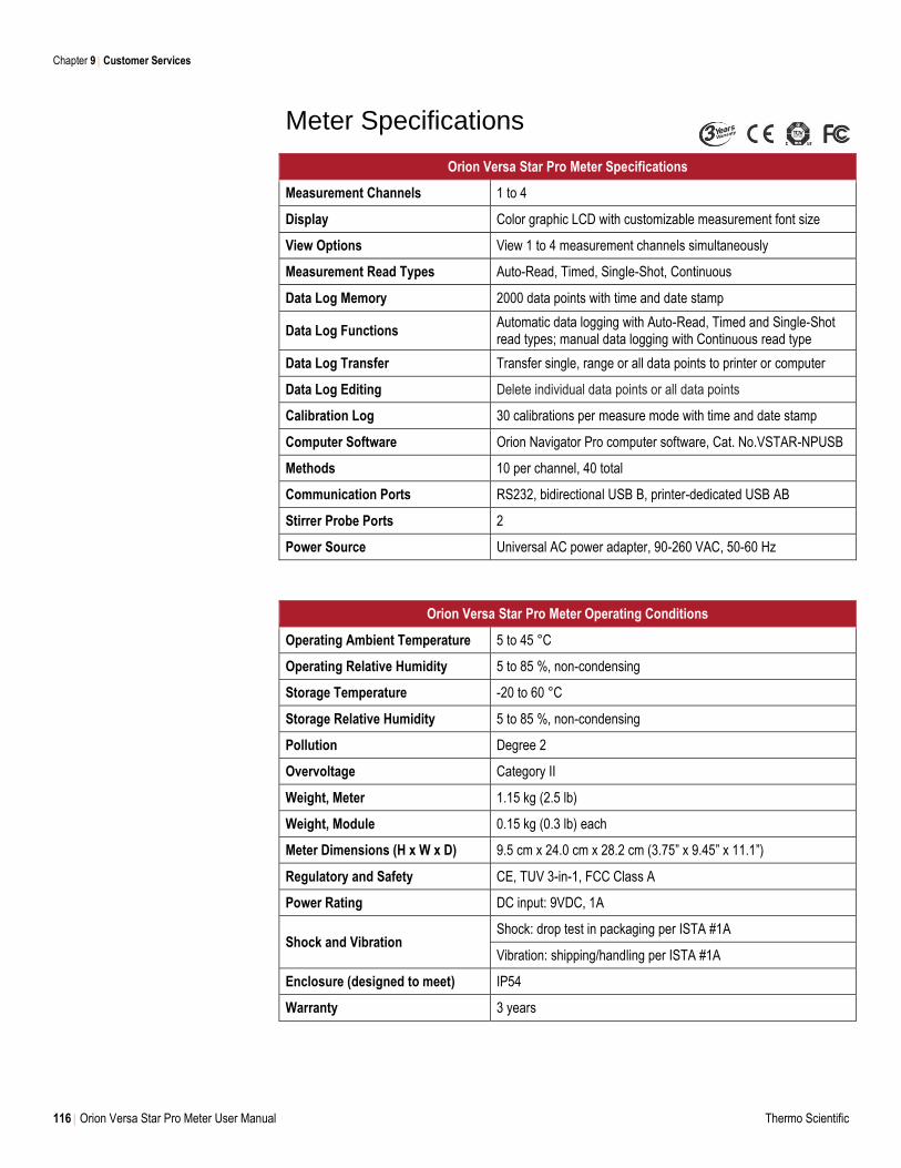
Chapter 9 Customer Services
116 Orion Versa Star Pro Meter User Manual Thermo Scientific
Meter Specifications
Orion Versa Star Pro Meter Specifications
Measurement Channels 1 to 4
Display Color graphic LCD with customizable measurement font size
View Options View 1 to 4 measurement channels simultaneously
Measurement Read Types Auto-Read, Timed, Single-Shot, Continuous
Data Log Memory 2000 data points with time and date stamp
Data Log Functions Automatic data logging with Auto-Read, Timed and Single-Shot read types; manual data logging with Continuous read type
Data Log Transfer Transfer single, range or all data points to printer or computer
Data Log Editing Delete individual data points or all data points
Calibration Log 30 calibrations per measure mode with time and date stamp
Computer Software Orion Navigator Pro computer software, Cat. No.VSTAR-NPUSB
Methods 10 per channel, 40 total
Communication Ports RS232, bidirectional USB B, printer-dedicated USB AB
Stirrer Probe Ports 2
Power Source Universal AC power adapter, 90-260 VAC, 50-60 Hz
Orion Versa Star Pro Meter Operating Conditions
Operating Ambient Temperature 5 to 45 °C
Operating Relative Humidity 5 to 85 %, non-condensing
Storage Temperature -20 to 60 °C
Storage Relative Humidity 5 to 85 %, non-condensing
Pollution Degree 2
Overvoltage Category II
Weight, Meter 1.15 kg (2.5 lb)
Weight, Module 0.15 kg (0.3 lb) each
Meter Dimensions (H x W x D) 9.5 cm x 24.0 cm x 28.2 cm (3.75” x 9.45” x 11.1”)
Regulatory and Safety CE, TUV 3-in-1, FCC Class A
Power Rating DC input: 9VDC, 1A
Shock and Vibration Shock: drop test in packaging per ISTA #1A
Vibration: shipping/handling per ISTA #1A
Enclosure (designed to meet) IP54
Warranty 3 years
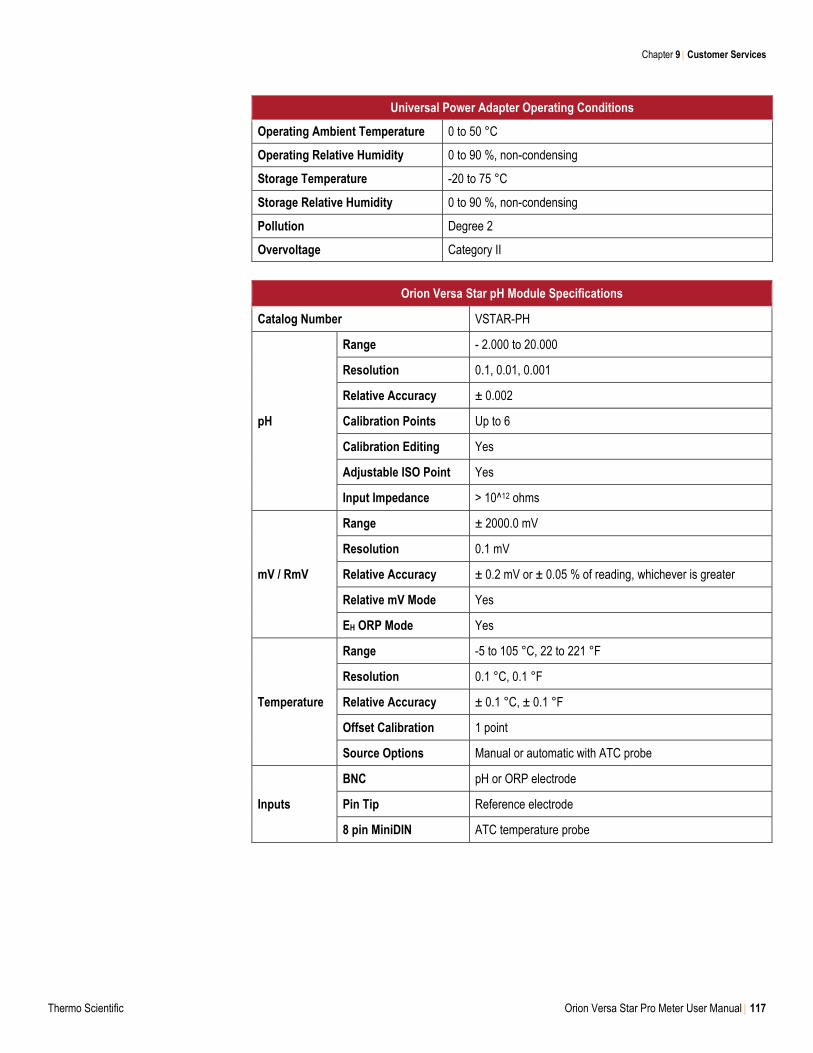
Chapter 9 Customer Services
Thermo Scientific Orion Versa Star Pro Meter User Manual 117
Universal Power Adapter Operating Conditions
Operating Ambient Temperature 0 to 50 °C
Operating Relative Humidity 0 to 90 %, non-condensing
Storage Temperature -20 to 75 °C
Storage Relative Humidity 0 to 90 %, non-condensing
Pollution Degree 2
Overvoltage Category II
Orion Versa Star pH Module Specifications
Catalog Number VSTAR-PH
pH
Range - 2.000 to 20.000
Resolution 0.1, 0.01, 0.001
Relative Accuracy ± 0.002
Calibration Points Up to 6
Calibration Editing Yes
Adjustable ISO Point Yes
Input Impedance > 10^12 ohms
mV / RmV
Range ± 2000.0 mV
Resolution 0.1 mV
Relative Accuracy ± 0.2 mV or ± 0.05 % of reading, whichever is greater
Relative mV Mode Yes
EH ORP Mode Yes
Temperature
Range -5 to 105 °C, 22 to 221 °F
Resolution 0.1 °C, 0.1 °F
Relative Accuracy ± 0.1 °C, ± 0.1 °F
Offset Calibration 1 point
Source Options Manual or automatic with ATC probe
Inputs
BNC pH or ORP electrode
Pin Tip Reference electrode
8 pin MiniDIN ATC temperature probe
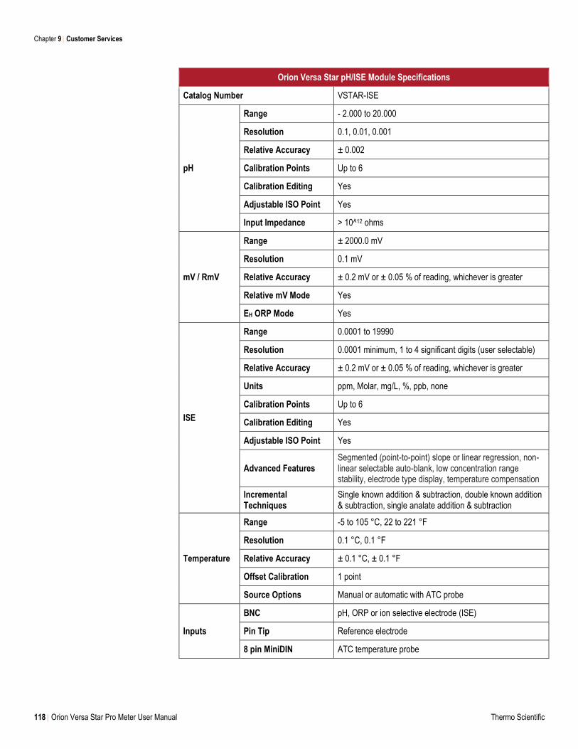
Chapter 9 Customer Services
118 Orion Versa Star Pro Meter User Manual Thermo Scientific
Orion Versa Star pH/ISE Module Specifications
Catalog Number VSTAR-ISE
pH
Range - 2.000 to 20.000
Resolution 0.1, 0.01, 0.001
Relative Accuracy ± 0.002
Calibration Points Up to 6
Calibration Editing Yes
Adjustable ISO Point Yes
Input Impedance > 10^12 ohms
mV / RmV
Range ± 2000.0 mV
Resolution 0.1 mV
Relative Accuracy ± 0.2 mV or ± 0.05 % of reading, whichever is greater
Relative mV Mode Yes
EH ORP Mode Yes
ISE
Range 0.0001 to 19990
Resolution 0.0001 minimum, 1 to 4 significant digits (user selectable)
Relative Accuracy ± 0.2 mV or ± 0.05 % of reading, whichever is greater
Units ppm, Molar, mg/L, %, ppb, none
Calibration Points Up to 6
Calibration Editing Yes
Adjustable ISO Point Yes
Advanced Features Segmented (point-to-point) slope or linear regression, non-linear selectable auto-blank, low concentration range stability, electrode type display, temperature compensation
Incremental Techniques
Single known addition & subtraction, double known addition & subtraction, single analate addition & subtraction
Temperature
Range -5 to 105 °C, 22 to 221 °F
Resolution 0.1 °C, 0.1 °F
Relative Accuracy ± 0.1 °C, ± 0.1 °F
Offset Calibration 1 point
Source Options Manual or automatic with ATC probe
Inputs
BNC pH, ORP or ion selective electrode (ISE)
Pin Tip Reference electrode
8 pin MiniDIN ATC temperature probe
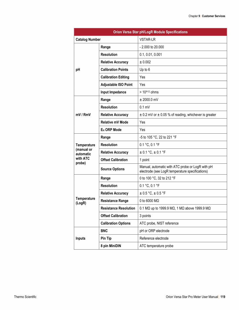
Chapter 9 Customer Services
Thermo Scientific Orion Versa Star Pro Meter User Manual 119
Orion Versa Star pH/LogR Module Specifications
Catalog Number VSTAR-LR
pH
Range - 2.000 to 20.000
Resolution 0.1, 0.01, 0.001
Relative Accuracy ± 0.002
Calibration Points Up to 6
Calibration Editing Yes
Adjustable ISO Point Yes
Input Impedance > 10^12 ohms
mV / RmV
Range ± 2000.0 mV
Resolution 0.1 mV
Relative Accuracy ± 0.2 mV or ± 0.05 % of reading, whichever is greater
Relative mV Mode Yes
EH ORP Mode Yes
Temperature (manual or automatic with ATC probe)
Range -5 to 105 °C, 22 to 221 °F
Resolution 0.1 °C, 0.1 °F
Relative Accuracy ± 0.1 °C, ± 0.1 °F
Offset Calibration 1 point
Source Options Manual, automatic with ATC probe or LogR with pH electrode (see LogR temperature specifications)
Temperature (LogR)
Range 0 to 100 °C, 32 to 212 °F
Resolution 0.1 °C, 0.1 °F
Relative Accuracy ± 0.5 °C, ± 0.5 °F
Resistance Range 0 to 6000 MΩ
Resistance Resolution 0.1 MΩ up to 1999.9 MΩ, 1 MΩ above 1999.9 MΩ
Offset Calibration 3 points
Calibration Options ATC probe, NIST reference
Inputs
BNC pH or ORP electrode
Pin Tip Reference electrode
8 pin MiniDIN ATC temperature probe
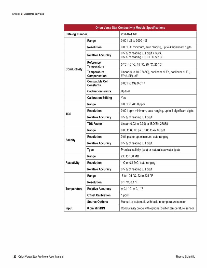
Chapter 9 Customer Services
120 Orion Versa Star Pro Meter User Manual Thermo Scientific
Orion Versa Star Conductivity Module Specifications
Catalog Number VSTAR-CND
Conductivity
Range 0.001 μS to 3000 mS
Resolution 0.001 μS minimum, auto ranging, up to 4 significant digits
Relative Accuracy 0.5 % of reading ± 1 digit > 3 μS, 0.5 % of reading ± 0.01 μS ≤ 3 μS
Reference Temperature
5 °C, 10 °C, 15 °C, 20 °C, 25 °C
Temperature Compensation
Linear (0 to 10.0 %/ºC), nonlinear nLFn, nonlinear nLFu, EP (USP), off
Compatible Cell Constants
0.001 to 199.9 cm-1
Calibration Points Up to 6
Calibration Editing Yes
TDS
Range 0.001 to 200.0 ppm
Resolution 0.001 ppm minimum, auto ranging, up to 4 significant digits
Relative Accuracy 0.5 % of reading ± 1 digit
TDS Factor Linear (0.02 to 9.99) or ISO/EN 27888
Salinity
Range 0.06 to 80.00 psu, 0.05 to 42.00 ppt
Resolution 0.01 psu or ppt minimum, auto ranging
Relative Accuracy 0.5 % of reading ± 1 digit
Type Practical salinity (psu) or natural sea water (ppt)
Resistivity
Range 2 Ω to 100 MΩ
Resolution 1 Ω or 0.1 MΩ, auto ranging
Relative Accuracy 0.5 % of reading ± 1 digit
Temperature
Range -5 to 105 °C, 22 to 221 °F
Resolution 0.1 °C, 0.1 °F
Relative Accuracy ± 0.1 °C, ± 0.1 °F
Offset Calibration 1 point
Source Options Manual or automatic with built-in temperature sensor
Input 8 pin MiniDIN Conductivity probe with optional built-in temperature sensor
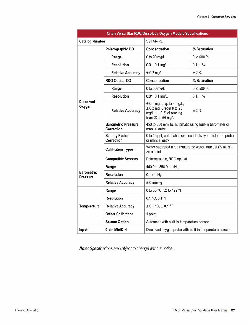
Chapter 9 Customer Services
Thermo Scientific Orion Versa Star Pro Meter User Manual 121
Orion Versa Star RDO/Dissolved Oxygen Module Specifications
Catalog Number VSTAR-RD
Dissolved Oxygen
Polarographic DO Concentration % Saturation
Range 0 to 90 mg/L 0 to 600 %
Resolution 0.01, 0.1 mg/L 0.1, 1 %
Relative Accuracy ± 0.2 mg/L ± 2 %
RDO Optical DO Concentration % Saturation
Range 0 to 50 mg/L 0 to 500 %
Resolution 0.01, 0.1 mg/L 0.1, 1 %
Relative Accuracy
± 0.1 mg /L up to 8 mg/L, ± 0.2 mg /L from 8 to 20 mg/L, ± 10 % of reading from 20 to 50 mg/L
± 2 %
Barometric Pressure Correction
450 to 850 mmHg, automatic using built-in barometer or manual entry
Salinity Factor Correction
0 to 45 ppt, automatic using conductivity module and probe or manual entry
Calibration Types Water saturated air, air saturated water, manual (Winkler), zero point
Compatible Sensors Polarographic, RDO optical
Barometric Pressure
Range 450.0 to 850.0 mmHg
Resolution 0.1 mmHg
Relative Accuracy ± 6 mmHg
Temperature
Range 0 to 50 °C, 32 to 122 °F
Resolution 0.1 °C, 0.1 °F
Relative Accuracy ± 0.1 °C, ± 0.1 °F
Offset Calibration 1 point
Source Option Automatic with built-in temperature sensor
Input 9 pin MiniDIN Dissolved oxygen probe with built-in temperature sensor
Note: Specifications are subject to change without notice.
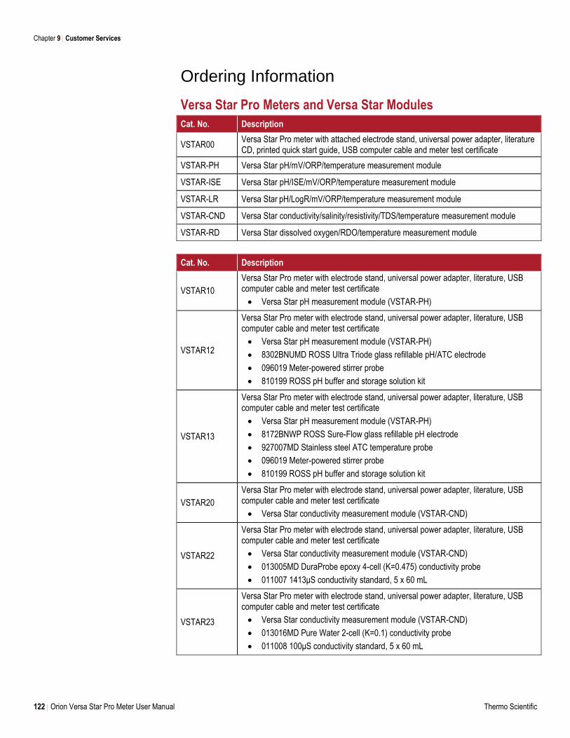
Chapter 9 Customer Services
122 Orion Versa Star Pro Meter User Manual Thermo Scientific
Ordering Information
Versa Star Pro Meters and Versa Star Modules
Cat. No. Description
VSTAR00 Versa Star Pro meter with attached electrode stand, universal power adapter, literature CD, printed quick start guide, USB computer cable and meter test certificate
VSTAR-PH Versa Star pH/mV/ORP/temperature measurement module
VSTAR-ISE Versa Star pH/ISE/mV/ORP/temperature measurement module
VSTAR-LR Versa Star pH/LogR/mV/ORP/temperature measurement module
VSTAR-CND Versa Star conductivity/salinity/resistivity/TDS/temperature measurement module
VSTAR-RD Versa Star dissolved oxygen/RDO/temperature measurement module
Cat. No. Description
VSTAR10
Versa Star Pro meter with electrode stand, universal power adapter, literature, USB computer cable and meter test certificate
Versa Star pH measurement module (VSTAR-PH)
VSTAR12
Versa Star Pro meter with electrode stand, universal power adapter, literature, USB computer cable and meter test certificate
Versa Star pH measurement module (VSTAR-PH)
8302BNUMD ROSS Ultra Triode glass refillable pH/ATC electrode
096019 Meter-powered stirrer probe
810199 ROSS pH buffer and storage solution kit
VSTAR13
Versa Star Pro meter with electrode stand, universal power adapter, literature, USB computer cable and meter test certificate
Versa Star pH measurement module (VSTAR-PH)
8172BNWP ROSS Sure-Flow glass refillable pH electrode
927007MD Stainless steel ATC temperature probe
096019 Meter-powered stirrer probe
810199 ROSS pH buffer and storage solution kit
VSTAR20
Versa Star Pro meter with electrode stand, universal power adapter, literature, USB computer cable and meter test certificate
Versa Star conductivity measurement module (VSTAR-CND)
VSTAR22
Versa Star Pro meter with electrode stand, universal power adapter, literature, USB computer cable and meter test certificate
Versa Star conductivity measurement module (VSTAR-CND)
013005MD DuraProbe epoxy 4-cell (K=0.475) conductivity probe
011007 1413μS conductivity standard, 5 x 60 mL
VSTAR23
Versa Star Pro meter with electrode stand, universal power adapter, literature, USB computer cable and meter test certificate
Versa Star conductivity measurement module (VSTAR-CND)
013016MD Pure Water 2-cell (K=0.1) conductivity probe
011008 100μS conductivity standard, 5 x 60 mL
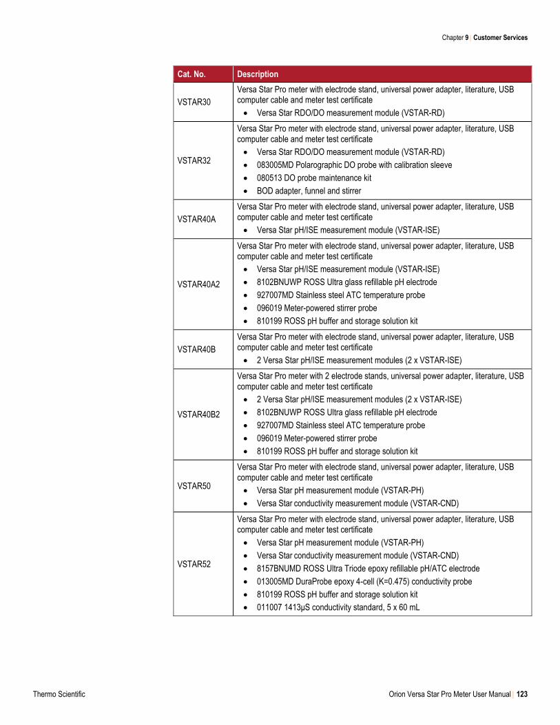
Chapter 9 Customer Services
Thermo Scientific Orion Versa Star Pro Meter User Manual 123
Cat. No. Description
VSTAR30
Versa Star Pro meter with electrode stand, universal power adapter, literature, USB computer cable and meter test certificate
Versa Star RDO/DO measurement module (VSTAR-RD)
VSTAR32
Versa Star Pro meter with electrode stand, universal power adapter, literature, USB computer cable and meter test certificate
Versa Star RDO/DO measurement module (VSTAR-RD)
083005MD Polarographic DO probe with calibration sleeve
080513 DO probe maintenance kit
BOD adapter, funnel and stirrer
VSTAR40A
Versa Star Pro meter with electrode stand, universal power adapter, literature, USB computer cable and meter test certificate
Versa Star pH/ISE measurement module (VSTAR-ISE)
VSTAR40A2
Versa Star Pro meter with electrode stand, universal power adapter, literature, USB computer cable and meter test certificate
Versa Star pH/ISE measurement module (VSTAR-ISE)
8102BNUWP ROSS Ultra glass refillable pH electrode
927007MD Stainless steel ATC temperature probe
096019 Meter-powered stirrer probe
810199 ROSS pH buffer and storage solution kit
VSTAR40B
Versa Star Pro meter with electrode stand, universal power adapter, literature, USB computer cable and meter test certificate
2 Versa Star pH/ISE measurement modules (2 x VSTAR-ISE)
VSTAR40B2
Versa Star Pro meter with 2 electrode stands, universal power adapter, literature, USB computer cable and meter test certificate
2 Versa Star pH/ISE measurement modules (2 x VSTAR-ISE)
8102BNUWP ROSS Ultra glass refillable pH electrode
927007MD Stainless steel ATC temperature probe
096019 Meter-powered stirrer probe
810199 ROSS pH buffer and storage solution kit
VSTAR50
Versa Star Pro meter with electrode stand, universal power adapter, literature, USB computer cable and meter test certificate
Versa Star pH measurement module (VSTAR-PH)
Versa Star conductivity measurement module (VSTAR-CND)
VSTAR52
Versa Star Pro meter with electrode stand, universal power adapter, literature, USB computer cable and meter test certificate
Versa Star pH measurement module (VSTAR-PH)
Versa Star conductivity measurement module (VSTAR-CND)
8157BNUMD ROSS Ultra Triode epoxy refillable pH/ATC electrode
013005MD DuraProbe epoxy 4-cell (K=0.475) conductivity probe
810199 ROSS pH buffer and storage solution kit
011007 1413μS conductivity standard, 5 x 60 mL
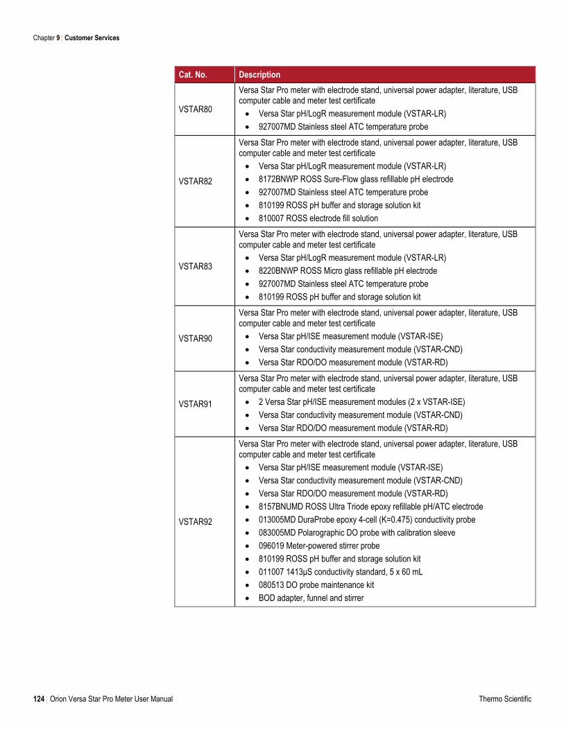
Chapter 9 Customer Services
124 Orion Versa Star Pro Meter User Manual Thermo Scientific
Cat. No. Description
VSTAR80
Versa Star Pro meter with electrode stand, universal power adapter, literature, USB computer cable and meter test certificate
Versa Star pH/LogR measurement module (VSTAR-LR)
927007MD Stainless steel ATC temperature probe
VSTAR82
Versa Star Pro meter with electrode stand, universal power adapter, literature, USB computer cable and meter test certificate
Versa Star pH/LogR measurement module (VSTAR-LR)
8172BNWP ROSS Sure-Flow glass refillable pH electrode
927007MD Stainless steel ATC temperature probe
810199 ROSS pH buffer and storage solution kit
810007 ROSS electrode fill solution
VSTAR83
Versa Star Pro meter with electrode stand, universal power adapter, literature, USB computer cable and meter test certificate
Versa Star pH/LogR measurement module (VSTAR-LR)
8220BNWP ROSS Micro glass refillable pH electrode
927007MD Stainless steel ATC temperature probe
810199 ROSS pH buffer and storage solution kit
VSTAR90
Versa Star Pro meter with electrode stand, universal power adapter, literature, USB computer cable and meter test certificate
Versa Star pH/ISE measurement module (VSTAR-ISE)
Versa Star conductivity measurement module (VSTAR-CND)
Versa Star RDO/DO measurement module (VSTAR-RD)
VSTAR91
Versa Star Pro meter with electrode stand, universal power adapter, literature, USB computer cable and meter test certificate
2 Versa Star pH/ISE measurement modules (2 x VSTAR-ISE)
Versa Star conductivity measurement module (VSTAR-CND)
Versa Star RDO/DO measurement module (VSTAR-RD)
VSTAR92
Versa Star Pro meter with electrode stand, universal power adapter, literature, USB computer cable and meter test certificate
Versa Star pH/ISE measurement module (VSTAR-ISE)
Versa Star conductivity measurement module (VSTAR-CND)
Versa Star RDO/DO measurement module (VSTAR-RD)
8157BNUMD ROSS Ultra Triode epoxy refillable pH/ATC electrode
013005MD DuraProbe epoxy 4-cell (K=0.475) conductivity probe
083005MD Polarographic DO probe with calibration sleeve
096019 Meter-powered stirrer probe
810199 ROSS pH buffer and storage solution kit
011007 1413μS conductivity standard, 5 x 60 mL
080513 DO probe maintenance kit
BOD adapter, funnel and stirrer
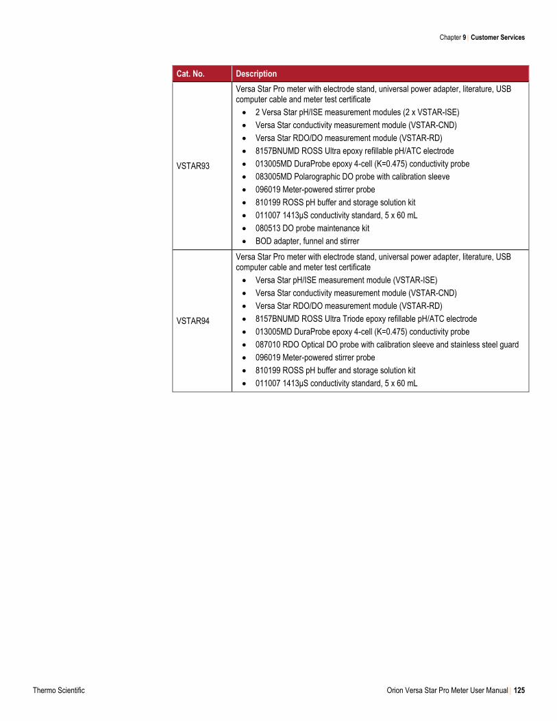
Chapter 9 Customer Services
Thermo Scientific Orion Versa Star Pro Meter User Manual 125
Cat. No. Description
VSTAR93
Versa Star Pro meter with electrode stand, universal power adapter, literature, USB computer cable and meter test certificate
2 Versa Star pH/ISE measurement modules (2 x VSTAR-ISE)
Versa Star conductivity measurement module (VSTAR-CND)
Versa Star RDO/DO measurement module (VSTAR-RD)
8157BNUMD ROSS Ultra epoxy refillable pH/ATC electrode
013005MD DuraProbe epoxy 4-cell (K=0.475) conductivity probe
083005MD Polarographic DO probe with calibration sleeve
096019 Meter-powered stirrer probe
810199 ROSS pH buffer and storage solution kit
011007 1413μS conductivity standard, 5 x 60 mL
080513 DO probe maintenance kit
BOD adapter, funnel and stirrer
VSTAR94
Versa Star Pro meter with electrode stand, universal power adapter, literature, USB computer cable and meter test certificate
Versa Star pH/ISE measurement module (VSTAR-ISE)
Versa Star conductivity measurement module (VSTAR-CND)
Versa Star RDO/DO measurement module (VSTAR-RD)
8157BNUMD ROSS Ultra Triode epoxy refillable pH/ATC electrode
013005MD DuraProbe epoxy 4-cell (K=0.475) conductivity probe
087010 RDO Optical DO probe with calibration sleeve and stainless steel guard
096019 Meter-powered stirrer probe
810199 ROSS pH buffer and storage solution kit
011007 1413μS conductivity standard, 5 x 60 mL
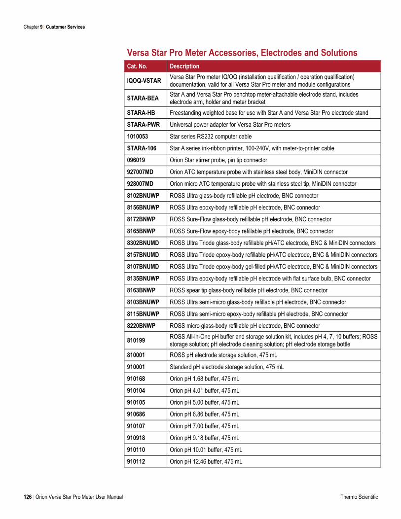
Chapter 9 Customer Services
126 Orion Versa Star Pro Meter User Manual Thermo Scientific
Versa Star Pro Meter Accessories, Electrodes and Solutions
Cat. No. Description
IQOQ-VSTAR Versa Star Pro meter IQ/OQ (installation qualification / operation qualification) documentation, valid for all Versa Star Pro meter and module configurations
STARA-BEA Star A and Versa Star Pro benchtop meter-attachable electrode stand, includes electrode arm, holder and meter bracket
STARA-HB Freestanding weighted base for use with Star A and Versa Star Pro electrode stand
STARA-PWR Universal power adapter for Versa Star Pro meters
1010053 Star series RS232 computer cable
STARA-106 Star A series ink-ribbon printer, 100-240V, with meter-to-printer cable
096019 Orion Star stirrer probe, pin tip connector
927007MD Orion ATC temperature probe with stainless steel body, MiniDIN connector
928007MD Orion micro ATC temperature probe with stainless steel tip, MiniDIN connector
8102BNUWP ROSS Ultra glass-body refillable pH electrode, BNC connector
8156BNUWP ROSS Ultra epoxy-body refillable pH electrode, BNC connector
8172BNWP ROSS Sure-Flow glass-body refillable pH electrode, BNC connector
8165BNWP ROSS Sure-Flow epoxy-body refillable pH electrode, BNC connector
8302BNUMD ROSS Ultra Triode glass-body refillable pH/ATC electrode, BNC & MiniDIN connectors
8157BNUMD ROSS Ultra Triode epoxy-body refillable pH/ATC electrode, BNC & MiniDIN connectors
8107BNUMD ROSS Ultra Triode epoxy-body gel-filled pH/ATC electrode, BNC & MiniDIN connectors
8135BNUWP ROSS Ultra epoxy-body refillable pH electrode with flat surface bulb, BNC connector
8163BNWP ROSS spear tip glass-body refillable pH electrode, BNC connector
8103BNUWP ROSS Ultra semi-micro glass-body refillable pH electrode, BNC connector
8115BNUWP ROSS Ultra semi-micro epoxy-body refillable pH electrode, BNC connector
8220BNWP ROSS micro glass-body refillable pH electrode, BNC connector
810199 ROSS All-in-One pH buffer and storage solution kit, includes pH 4, 7, 10 buffers; ROSS storage solution; pH electrode cleaning solution; pH electrode storage bottle
810001 ROSS pH electrode storage solution, 475 mL
910001 Standard pH electrode storage solution, 475 mL
910168 Orion pH 1.68 buffer, 475 mL
910104 Orion pH 4.01 buffer, 475 mL
910105 Orion pH 5.00 buffer, 475 mL
910686 Orion pH 6.86 buffer, 475 mL
910107 Orion pH 7.00 buffer, 475 mL
910918 Orion pH 9.18 buffer, 475 mL
910110 Orion pH 10.01 buffer, 475 mL
910112 Orion pH 12.46 buffer, 475 mL
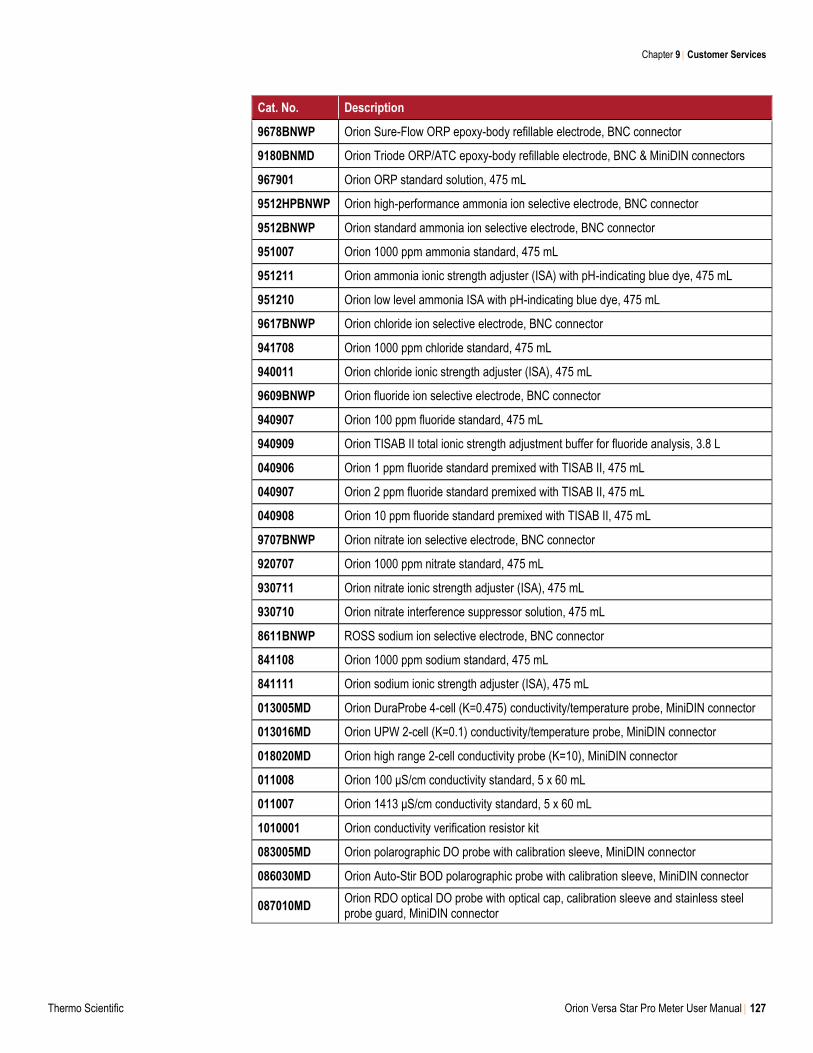
Chapter 9 Customer Services
Thermo Scientific Orion Versa Star Pro Meter User Manual 127
Cat. No. Description
9678BNWP Orion Sure-Flow ORP epoxy-body refillable electrode, BNC connector
9180BNMD Orion Triode ORP/ATC epoxy-body refillable electrode, BNC & MiniDIN connectors
967901 Orion ORP standard solution, 475 mL
9512HPBNWP Orion high-performance ammonia ion selective electrode, BNC connector
9512BNWP Orion standard ammonia ion selective electrode, BNC connector
951007 Orion 1000 ppm ammonia standard, 475 mL
951211 Orion ammonia ionic strength adjuster (ISA) with pH-indicating blue dye, 475 mL
951210 Orion low level ammonia ISA with pH-indicating blue dye, 475 mL
9617BNWP Orion chloride ion selective electrode, BNC connector
941708 Orion 1000 ppm chloride standard, 475 mL
940011 Orion chloride ionic strength adjuster (ISA), 475 mL
9609BNWP Orion fluoride ion selective electrode, BNC connector
940907 Orion 100 ppm fluoride standard, 475 mL
940909 Orion TISAB II total ionic strength adjustment buffer for fluoride analysis, 3.8 L
040906 Orion 1 ppm fluoride standard premixed with TISAB II, 475 mL
040907 Orion 2 ppm fluoride standard premixed with TISAB II, 475 mL
040908 Orion 10 ppm fluoride standard premixed with TISAB II, 475 mL
9707BNWP Orion nitrate ion selective electrode, BNC connector
920707 Orion 1000 ppm nitrate standard, 475 mL
930711 Orion nitrate ionic strength adjuster (ISA), 475 mL
930710 Orion nitrate interference suppressor solution, 475 mL
8611BNWP ROSS sodium ion selective electrode, BNC connector
841108 Orion 1000 ppm sodium standard, 475 mL
841111 Orion sodium ionic strength adjuster (ISA), 475 mL
013005MD Orion DuraProbe 4-cell (K=0.475) conductivity/temperature probe, MiniDIN connector
013016MD Orion UPW 2-cell (K=0.1) conductivity/temperature probe, MiniDIN connector
018020MD Orion high range 2-cell conductivity probe (K=10), MiniDIN connector
011008 Orion 100 μS/cm conductivity standard, 5 x 60 mL
011007 Orion 1413 μS/cm conductivity standard, 5 x 60 mL
1010001 Orion conductivity verification resistor kit
083005MD Orion polarographic DO probe with calibration sleeve, MiniDIN connector
086030MD Orion Auto-Stir BOD polarographic probe with calibration sleeve, MiniDIN connector
087010MD Orion RDO optical DO probe with optical cap, calibration sleeve and stainless steel probe guard, MiniDIN connector
128 Orion Versa Star Pro Meter User Manual Thermo Scientific
A Channel Specific Settings and Features
Within the Channel 1, Channel 2, Channel 3 and Channel 4 setup menus is the Mode menu,
which can be used to customize measurement settings and parameters for the selected
channel. This section provides detailed information on the options available within Mode menus
when using the various Versa Star measurement modules. Detailed information on additional
advanced meter features is also provided.
General Mode Settings
Sample ID
If Manual is selected as the type of Sample ID, use the popup alphanumeric keypad screen to
enter a sample ID up to ten characters long. The entered sample ID will be recorded with
subsequent measurements and saved to the data log or exported to an external device,
depending on the meter communication settings in the Instrument Settings setup menu.
If Auto Incremental is selected as the type of Sample ID, use the popup numeric keypad screen
to enter a numeric value up to ten characters long. The entered sample ID will be used as the
starting value and the meter will automatically increase the value by one for each subsequent
measurement. The sample IDs will be recorded with each measurement and saved to the data
log or exported to an external device, depending on the meter communication settings in the
Instrument Settings setup menu.
Press the f2 (Sample ID) key in the measurement mode to open a shortcut to the Sample ID
setup menu and enter a new sample ID.
Appendix A
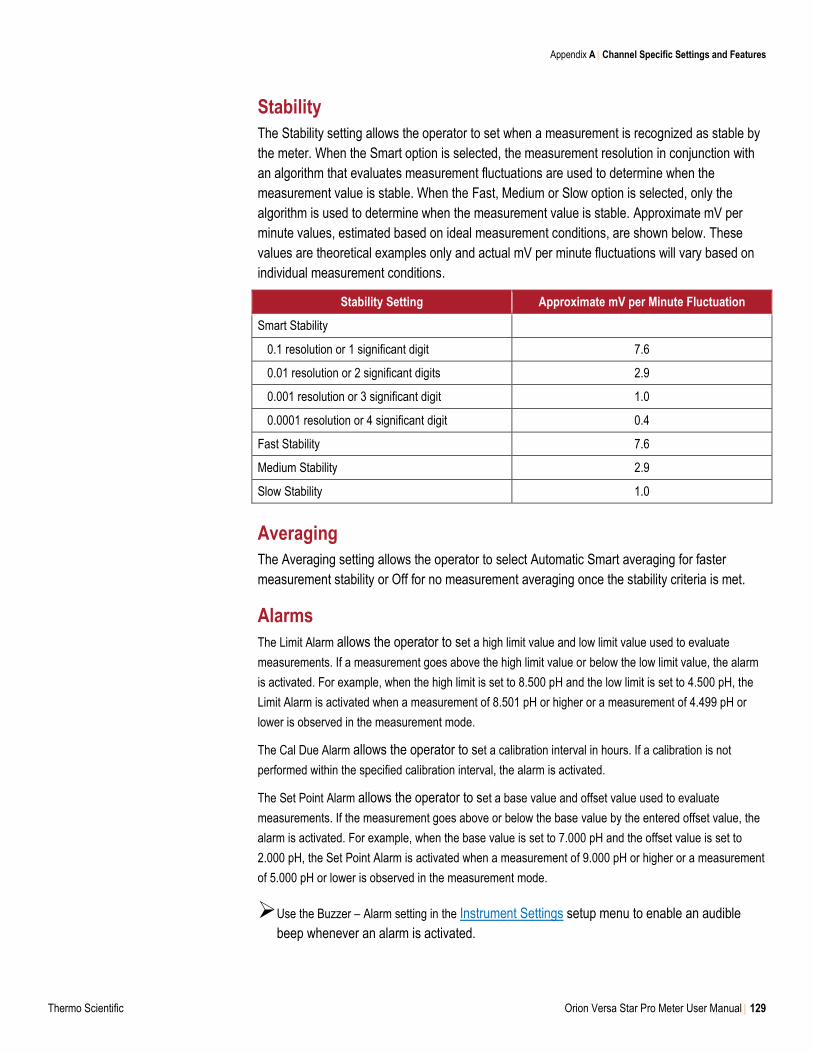
Appendix A Channel Specific Settings and Features
Thermo Scientific Orion Versa Star Pro Meter User Manual 129
Stability
The Stability setting allows the operator to set when a measurement is recognized as stable by
the meter. When the Smart option is selected, the measurement resolution in conjunction with
an algorithm that evaluates measurement fluctuations are used to determine when the
measurement value is stable. When the Fast, Medium or Slow option is selected, only the
algorithm is used to determine when the measurement value is stable. Approximate mV per
minute values, estimated based on ideal measurement conditions, are shown below. These
values are theoretical examples only and actual mV per minute fluctuations will vary based on
individual measurement conditions.
Stability Setting Approximate mV per Minute Fluctuation
Smart Stability
0.1 resolution or 1 significant digit 7.6
0.01 resolution or 2 significant digits 2.9
0.001 resolution or 3 significant digit 1.0
0.0001 resolution or 4 significant digit 0.4
Fast Stability 7.6
Medium Stability 2.9
Slow Stability 1.0
Averaging
The Averaging setting allows the operator to select Automatic Smart averaging for faster
measurement stability or Off for no measurement averaging once the stability criteria is met.
Alarms
The Limit Alarm allows the operator to set a high limit value and low limit value used to evaluate
measurements. If a measurement goes above the high limit value or below the low limit value, the alarm
is activated. For example, when the high limit is set to 8.500 pH and the low limit is set to 4.500 pH, the
Limit Alarm is activated when a measurement of 8.501 pH or higher or a measurement of 4.499 pH or
lower is observed in the measurement mode.
The Cal Due Alarm allows the operator to set a calibration interval in hours. If a calibration is not
performed within the specified calibration interval, the alarm is activated.
The Set Point Alarm allows the operator to set a base value and offset value used to evaluate
measurements. If the measurement goes above or below the base value by the entered offset value, the
alarm is activated. For example, when the base value is set to 7.000 pH and the offset value is set to
2.000 pH, the Set Point Alarm is activated when a measurement of 9.000 pH or higher or a measurement
of 5.000 pH or lower is observed in the measurement mode.
Use the Buzzer – Alarm setting in the Instrument Settings setup menu to enable an audible
beep whenever an alarm is activated.
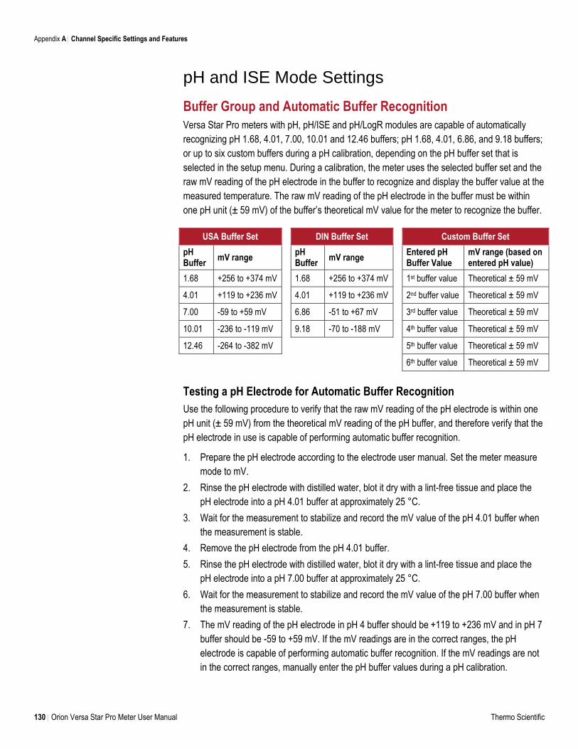
Appendix A Channel Specific Settings and Features
130 Orion Versa Star Pro Meter User Manual Thermo Scientific
pH and ISE Mode Settings
Buffer Group and Automatic Buffer Recognition
Versa Star Pro meters with pH, pH/ISE and pH/LogR modules are capable of automatically
recognizing pH 1.68, 4.01, 7.00, 10.01 and 12.46 buffers; pH 1.68, 4.01, 6.86, and 9.18 buffers;
or up to six custom buffers during a pH calibration, depending on the pH buffer set that is
selected in the setup menu. During a calibration, the meter uses the selected buffer set and the
raw mV reading of the pH electrode in the buffer to recognize and display the buffer value at the
measured temperature. The raw mV reading of the pH electrode in the buffer must be within
one pH unit (± 59 mV) of the buffer’s theoretical mV value for the meter to recognize the buffer.
USA Buffer Set DIN Buffer Set Custom Buffer Set
pH Buffer
mV range pH Buffer
mV range Entered pH Buffer Value
mV range (based on entered pH value)
1.68 +256 to +374 mV 1.68 +256 to +374 mV 1st buffer value Theoretical ± 59 mV
4.01 +119 to +236 mV 4.01 +119 to +236 mV 2nd buffer value Theoretical ± 59 mV
7.00 -59 to +59 mV 6.86 -51 to +67 mV 3rd buffer value Theoretical ± 59 mV
10.01 -236 to -119 mV 9.18 -70 to -188 mV 4th buffer value Theoretical ± 59 mV
12.46 -264 to -382 mV 5th buffer value Theoretical ± 59 mV
6th buffer value Theoretical ± 59 mV
Testing a pH Electrode for Automatic Buffer Recognition
Use the following procedure to verify that the raw mV reading of the pH electrode is within one
pH unit (± 59 mV) from the theoretical mV reading of the pH buffer, and therefore verify that the
pH electrode in use is capable of performing automatic buffer recognition.
1. Prepare the pH electrode according to the electrode user manual. Set the meter measure
mode to mV.
2. Rinse the pH electrode with distilled water, blot it dry with a lint-free tissue and place the
pH electrode into a pH 4.01 buffer at approximately 25 °C.
3. Wait for the measurement to stabilize and record the mV value of the pH 4.01 buffer when
the measurement is stable.
4. Remove the pH electrode from the pH 4.01 buffer.
5. Rinse the pH electrode with distilled water, blot it dry with a lint-free tissue and place the
pH electrode into a pH 7.00 buffer at approximately 25 °C.
6. Wait for the measurement to stabilize and record the mV value of the pH 7.00 buffer when
the measurement is stable.
7. The mV reading of the pH electrode in pH 4 buffer should be +119 to +236 mV and in pH 7
buffer should be -59 to +59 mV. If the mV readings are in the correct ranges, the pH
electrode is capable of performing automatic buffer recognition. If the mV readings are not
in the correct ranges, manually enter the pH buffer values during a pH calibration.
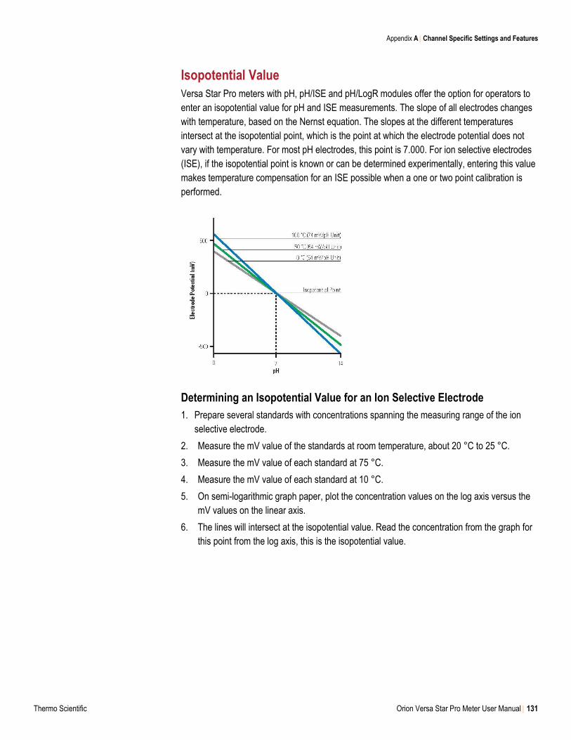
Appendix A Channel Specific Settings and Features
Thermo Scientific Orion Versa Star Pro Meter User Manual 131
Isopotential Value
Versa Star Pro meters with pH, pH/ISE and pH/LogR modules offer the option for operators to
enter an isopotential value for pH and ISE measurements. The slope of all electrodes changes
with temperature, based on the Nernst equation. The slopes at the different temperatures
intersect at the isopotential point, which is the point at which the electrode potential does not
vary with temperature. For most pH electrodes, this point is 7.000. For ion selective electrodes
(ISE), if the isopotential point is known or can be determined experimentally, entering this value
makes temperature compensation for an ISE possible when a one or two point calibration is
performed.
Determining an Isopotential Value for an Ion Selective Electrode
1. Prepare several standards with concentrations spanning the measuring range of the ion
selective electrode.
2. Measure the mV value of the standards at room temperature, about 20 °C to 25 °C.
3. Measure the mV value of each standard at 75 °C.
4. Measure the mV value of each standard at 10 °C.
5. On semi-logarithmic graph paper, plot the concentration values on the log axis versus the
mV values on the linear axis.
6. The lines will intersect at the isopotential value. Read the concentration from the graph for
this point from the log axis, this is the isopotential value.
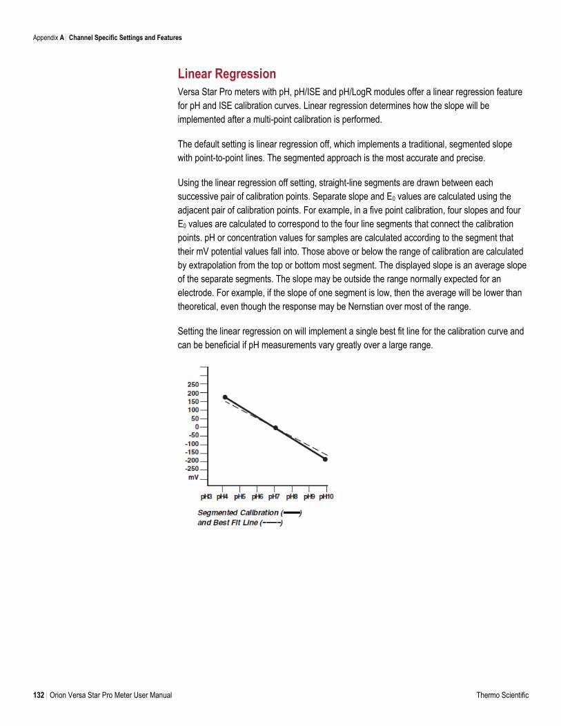
Appendix A Channel Specific Settings and Features
132 Orion Versa Star Pro Meter User Manual Thermo Scientific
Linear Regression
Versa Star Pro meters with pH, pH/ISE and pH/LogR modules offer a linear regression feature
for pH and ISE calibration curves. Linear regression determines how the slope will be
implemented after a multi-point calibration is performed.
The default setting is linear regression off, which implements a traditional, segmented slope
with point-to-point lines. The segmented approach is the most accurate and precise.
Using the linear regression off setting, straight-line segments are drawn between each
successive pair of calibration points. Separate slope and E0 values are calculated using the
adjacent pair of calibration points. For example, in a five point calibration, four slopes and four
E0 values are calculated to correspond to the four line segments that connect the calibration
points. pH or concentration values for samples are calculated according to the segment that
their mV potential values fall into. Those above or below the range of calibration are calculated
by extrapolation from the top or bottom most segment. The displayed slope is an average slope
of the separate segments. The slope may be outside the range normally expected for an
electrode. For example, if the slope of one segment is low, then the average will be lower than
theoretical, even though the response may be Nernstian over most of the range.
Setting the linear regression on will implement a single best fit line for the calibration curve and
can be beneficial if pH measurements vary greatly over a large range.
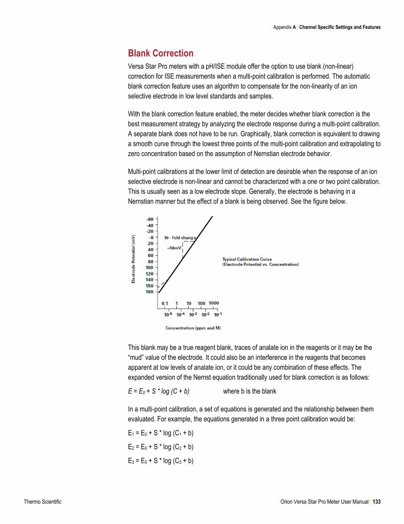
Appendix A Channel Specific Settings and Features
Thermo Scientific Orion Versa Star Pro Meter User Manual 133
Blank Correction
Versa Star Pro meters with a pH/ISE module offer the option to use blank (non-linear)
correction for ISE measurements when a multi-point calibration is performed. The automatic
blank correction feature uses an algorithm to compensate for the non-linearity of an ion
selective electrode in low level standards and samples.
With the blank correction feature enabled, the meter decides whether blank correction is the
best measurement strategy by analyzing the electrode response during a multi-point calibration.
A separate blank does not have to be run. Graphically, blank correction is equivalent to drawing
a smooth curve through the lowest three points of the multi-point calibration and extrapolating to
zero concentration based on the assumption of Nernstian electrode behavior.
Multi-point calibrations at the lower limit of detection are desirable when the response of an ion
selective electrode is non-linear and cannot be characterized with a one or two point calibration.
This is usually seen as a low electrode slope. Generally, the electrode is behaving in a
Nernstian manner but the effect of a blank is being observed. See the figure below.
This blank may be a true reagent blank, traces of analate ion in the reagents or it may be the
“mud” value of the electrode. It could also be an interference in the reagents that becomes
apparent at low levels of analate ion, or it could be any combination of these effects. The
expanded version of the Nernst equation traditionally used for blank correction is as follows:
E = E0 + S * log (C + b) where b is the blank
In a multi-point calibration, a set of equations is generated and the relationship between them
evaluated. For example, the equations generated in a three point calibration would be:
E1 = E0 + S * log (C1 + b)
E2 = E0 + S * log (C2 + b)
E3 = E0 + S * log (C3 + b)
Appendix A Channel Specific Settings and Features
134 Orion Versa Star Pro Meter User Manual Thermo Scientific
The meter evaluates the relationships between the three potentials E1, E2 and E3 and the three
concentrations C1, C2 and C3. If the relationships indicate that blank correction is desired, a
blank will automatically be calculated and the non-linearity will be corrected for in a Nernstian
manner. If the appropriate conditions are not met, the blank is set at zero and each segment of
the multi-point calibration is treated independently.
When all three of the following conditions are met, blank correction is invoked.
1. The concentration of the first standard is zero, or the slope of the electrode between the
first and second standards is less than the slope between the second and third.
2. Potential differences between points are significant. For example, E3 - E1 > 10 mV
3. The blank correction algorithm converges at reasonable blank and slope values.
Conditions in steps 1 and 2 prevent failure to converge in most situations. However, the
slope will attain any value necessary for convergence to a calculated blank value of 3 x C3.
When blank correction is implemented, the slope value for the electrode may be outside the
range of values normally considered acceptable during an ordinary calibration. For best results,
calibration standards should be close in range to the expected sample concentrations and
should bracket the expected sample concentration. When conditions 1, 2 and 3 are not met, the
calibration data is handled by the multi-point calibration method described earlier.
In calibrations with more than three points, a combination of methods is utilized. Automatic
blank correction is used if the lowest three points satisfy the criteria and multi-point calibration is
used for the other points. The slope calculated in the automatic blank correction algorithm and
the slopes for each additional segment are used to calculate the average slope.
Low Level Stability
Versa Star Pro meters with a pH/ISE module offer the option to use the low level stability
feature when calibrating ion selective electrodes. The low level stability feature improves the
accuracy of low concentration ISE measurements by adjusting the timing for calibration points
of low level standards, allowing a longer stabilization time for the electrode in the calibration
standards. The stabilization time is typically extended to about three to five minutes per
calibration point, but will vary based on the actual readings from the electrode during
calibration.
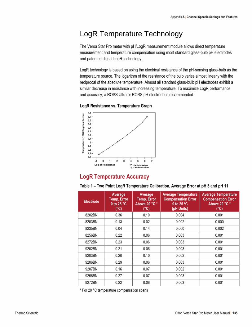
Appendix A Channel Specific Settings and Features
Thermo Scientific Orion Versa Star Pro Meter User Manual 135
LogR Temperature Technology
The Versa Star Pro meter with pH/LogR measurement module allows direct temperature
measurement and temperature compensation using most standard glass-bulb pH electrodes
and patented digital LogR technology.
LogR technology is based on using the electrical resistance of the pH-sensing glass-bulb as the
temperature source. The logarithm of the resistance of the bulb varies almost linearly with the
reciprocal of the absolute temperature. Almost all standard glass-bulb pH electrodes exhibit a
similar decrease in resistance with increasing temperature. To maximize LogR performance
and accuracy, a ROSS Ultra or ROSS pH electrode is recommended.
LogR Resistance vs. Temperature Graph
LogR Temperature Accuracy
Table 1 – Two Point LogR Temperature Calibration, Average Error at pH 3 and pH 11
Electrode
Average Temp. Error 0 to 25 °C
(°C)
Average Temp. Error
Above 20 °C * (°C)
Average Temperature Compensation Error
0 to 25 ºC (pH Units)
Average Temperature Compensation Error
Above 20 °C * (°C)
8202BN 0.36 0.10 0.004 0.001
8203BN 0.13 0.02 0.002 0.000
8235BN 0.04 0.14 0.000 0.002
8256BN 0.22 0.06 0.003 0.001
8272BN 0.23 0.06 0.003 0.001
9202BN 0.21 0.06 0.003 0.001
9203BN 0.20 0.10 0.002 0.001
9206BN 0.29 0.06 0.003 0.001
9207BN 0.16 0.07 0.002 0.001
9256BN 0.27 0.07 0.003 0.001
9272BN 0.22 0.06 0.003 0.001
* For 20 °C temperature compensation spans
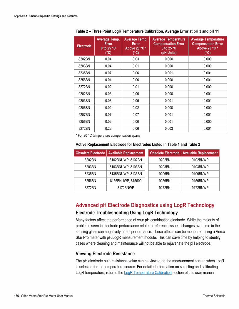
Appendix A Channel Specific Settings and Features
136 Orion Versa Star Pro Meter User Manual Thermo Scientific
Table 2 – Three Point LogR Temperature Calibration, Average Error at pH 3 and pH 11
Electrode
Average Temp. Error
0 to 25 °C (°C)
Average Temp. Error
Above 20 °C * (°C)
Average Temperature Compensation Error
0 to 25 ºC (pH Units)
Average Temperature Compensation Error
Above 20 °C * (°C)
8202BN 0.04 0.03 0.000 0.000
8203BN 0.04 0.01 0.000 0.000
8235BN 0.07 0.06 0.001 0.001
8256BN 0.04 0.06 0.000 0.001
8272BN 0.02 0.01 0.000 0.000
9202BN 0.03 0.06 0.000 0.001
9203BN 0.06 0.05 0.001 0.001
9206BN 0.02 0.02 0.000 0.000
9207BN 0.07 0.07 0.001 0.001
9256BN 0.02 0.00 0.001 0.000
9272BN 0.22 0.06 0.003 0.001
* For 20 °C temperature compensation spans
Active Replacement Electrode for Electrodes Listed in Table 1 and Table 2
Obsolete Electrode Available Replacement Obsolete Electrode Available Replacement
8202BN 8102BNUWP, 8102BN 9202BN 9102BNWP
8203BN 8103BNUWP, 8103BN 9203BN 9103BNWP
8235BN 8135BNUWP, 8135BN 9206BN 9106BNWP
8256BN 8156BNUWP, 815600 9256BN 9156BNWP
8272BN 8172BNWP 9272BN 9172BNWP
Advanced pH Electrode Diagnostics using LogR Technology
Electrode Troubleshooting Using LogR Technology
Many factors affect the performance of your pH combination electrode. While the majority of
problems seen in electrode performance relate to reference issues, changes over time in the
sensing glass can negatively affect performance. These effects can be monitored using a Versa
Star Pro meter with pH/LogR measurement module. This can save time by helping to identify
cases where cleaning and maintenance will not be able to rejuvenate the pH electrode.
Viewing Electrode Resistance
The pH electrode bulb resistance value can be viewed on the measurement screen when LogR
is selected for the temperature source. For detailed information on selecting and calibrating
LogR temperature, refer to the LogR Temperature Calibration section of this user manual.
Appendix A Channel Specific Settings and Features
Thermo Scientific Orion Versa Star Pro Meter User Manual 137
Out-Of-The-Box Electrode Check
Follow this procedure to perform a quick evaluation of a new pH electrode and help diagnose a
defective pH electrode.
1. Remove the pH electrode from the box.
2. Connect the pH electrode to the BNC input on the pH/LogR module connected with the
Versa Star Pro meter.
3. If needed, select LogR as the temperature source:
a. In the measurement mode, press the setup key
b. Press the ◄ or ► key to highlight Channel # (the channel number the LogR module is
connected with) and press the f3 (Select) key.
c. Press the ◄ or ►key to highlight Temperature and press the f3 (Select) key.
d. Press the ▲ or ▼ key to highlight Temperature Input and press the ◄ or ► key to
highlight the channel number the LogR module is connected with (i.e. Ch2-LogR).
e. Press the measure (esc) key to return to the measurement mode.
4. Read the resistance value shown on the measurement display.
a. A resistance value of 0 indicates that the pH electrode may be defective.
b. A resistance value other than 0 indicates the pH electrode is responsive. Prepare the
pH electrode according to the instructions in the electrode user manual. Perform the
initial electrode check when the electrode is ready.
Initial Electrode Check
For the most pH electrode diagnostics benefits from the Versa Star Pro meter with pH/LogR
measurement module, establish a regular schedule of resistance testing with the pH electrode.
Perform an initial check of the pH electrode resistance and record the temperature and
resistance value in the provided table, or perform a LogR temperature calibration and export the
calibration information to a computer or printer.
1. Rinse the pH electrode with deionized water and blot dry with a lint-free tissue.
2. Insert the pH electrode into the solution and gently stir the solution.
3. Record the temperature and resistance value for reference.
The pH-sensing bulb thickness and diameter vary among pH electrodes, resulting in normal
variations in resistance values. In most cases, the initial value is not a definitive test of electrode
condition except in extreme cases such as the initial low readings information described below.
When changing pH electrodes, do not be alarmed if the resistance varies dramatically from your
previous electrode.
Initial Low Readings – If the resistance is below 1 MΩ in a solution at room temperature (22 to
27 °C), it indicates a damaged pH electrode. In this case, the electrode will most likely need to
be replaced.
Appendix A Channel Specific Settings and Features
138 Orion Versa Star Pro Meter User Manual Thermo Scientific
Periodic Electrode Testing
Periodically check the pH electrode resistance following the steps above and record resistance
values in the provided table. Diagnostic testing at 25 °C is ideal, due to the resistance stability
at this temperature. It is important to keep as many sampling variables constant as possible to
get the most out of the periodic resistance testing. The resistance reading is fully dependent on
temperature. When testing, use the same solution at a known, stable temperature each time
and measure around the same temperature each time.
Small Variances in Resistance – Resistance will typically increase as the pH-sensing bulb
ages. This is no cause for concern. Over time, this can lead to slower response rates, slope
degradation and reduced immunity to noise. By keeping track of the change in resistance
(delta, as listed in the table as an example), this information may be used to determine when to
replace the pH electrode before failure occurs, eliminating down time.
Large Decreases in Resistance – When the pH-sensing glass membrane resistance is more
than ten times lower than the expected resistance value at a given temperature, it is often an
indication of a crack in the bulb or shorting of the electrode, leading to a total failure in function.
If you see this type of change in the resistance reading, most likely no further testing or care will
resolve the problem and a new pH electrode will be needed.
Increases in Resistance – As the electrode ages, the resistance of the glass pH-sensing bulb
increases. Eventually, the aging of the electrode, and visible increase in resistance, manifests
in a slower response rate, low slope, and reduced immunity to noise. At some point, the
resistance becomes “super high”. The pH electrode diagnostics from the Versa Star Pro meter
with pH/LogR measurement module help pinpoint causes of reduced pH electrode performance
and quickly show the effectiveness of cleaning and care processes.
If the resistance values are not out of expected range, but electrode response continues to
be slow or erratic, these effects may also be seen because of reference clogging or
contamination. Follow the cleaning procedures in the pH electrode user manual.
If the resistance value between checks increases substantially higher, the fill solution may
be depleted. Follow the cleaning and filling procedures in the pH electrode user manual.
If the resistance values show a “super high” resistance, cleaning and care may improve
performance, but will not be able to return the probe to like new condition. Consider
purchasing a new electrode.
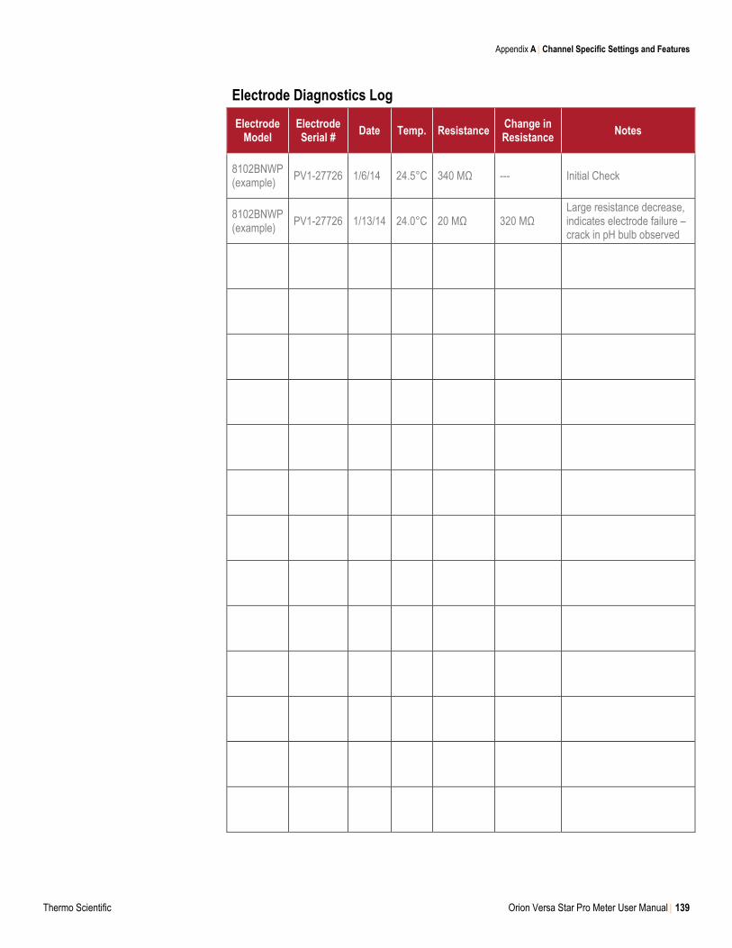
Appendix A Channel Specific Settings and Features
Thermo Scientific Orion Versa Star Pro Meter User Manual 139
Electrode Diagnostics Log
Electrode Model
Electrode Serial #
Date Temp. Resistance Change in Resistance
Notes
8102BNWP (example)
PV1-27726 1/6/14 24.5°C 340 MΩ --- Initial Check
8102BNWP (example)
PV1-27726 1/13/14 24.0°C 20 MΩ 320 MΩ Large resistance decrease, indicates electrode failure – crack in pH bulb observed
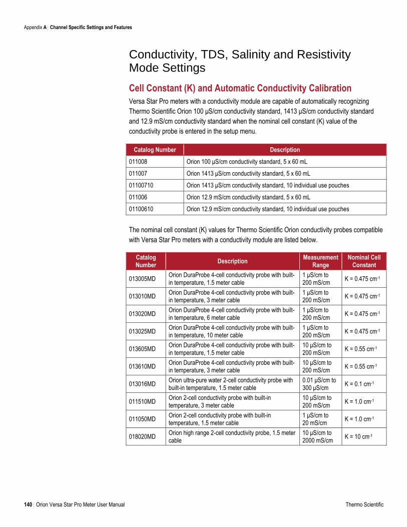
Appendix A Channel Specific Settings and Features
140 Orion Versa Star Pro Meter User Manual Thermo Scientific
Conductivity, TDS, Salinity and Resistivity Mode Settings
Cell Constant (K) and Automatic Conductivity Calibration
Versa Star Pro meters with a conductivity module are capable of automatically recognizing
Thermo Scientific Orion 100 μS/cm conductivity standard, 1413 μS/cm conductivity standard
and 12.9 mS/cm conductivity standard when the nominal cell constant (K) value of the
conductivity probe is entered in the setup menu.
Catalog Number Description
011008 Orion 100 μS/cm conductivity standard, 5 x 60 mL
011007 Orion 1413 μS/cm conductivity standard, 5 x 60 mL
01100710 Orion 1413 μS/cm conductivity standard, 10 individual use pouches
011006 Orion 12.9 mS/cm conductivity standard, 5 x 60 mL
01100610 Orion 12.9 mS/cm conductivity standard, 10 individual use pouches
The nominal cell constant (K) values for Thermo Scientific Orion conductivity probes compatible
with Versa Star Pro meters with a conductivity module are listed below.
Catalog Number
Description Measurement
Range Nominal Cell
Constant
013005MD Orion DuraProbe 4-cell conductivity probe with built-in temperature, 1.5 meter cable
1 μS/cm to 200 mS/cm
K = 0.475 cm-1
013010MD Orion DuraProbe 4-cell conductivity probe with built-in temperature, 3 meter cable
1 μS/cm to 200 mS/cm
K = 0.475 cm-1
013020MD Orion DuraProbe 4-cell conductivity probe with built-in temperature, 6 meter cable
1 μS/cm to 200 mS/cm
K = 0.475 cm-1
013025MD Orion DuraProbe 4-cell conductivity probe with built-in temperature, 10 meter cable
1 μS/cm to 200 mS/cm
K = 0.475 cm-1
013605MD Orion DuraProbe 4-cell conductivity probe with built-in temperature, 1.5 meter cable
10 μS/cm to 200 mS/cm
K = 0.55 cm-1
013610MD Orion DuraProbe 4-cell conductivity probe with built-in temperature, 3 meter cable
10 μS/cm to 200 mS/cm
K = 0.55 cm-1
013016MD Orion ultra-pure water 2-cell conductivity probe with built-in temperature, 1.5 meter cable
0.01 μS/cm to 300 μS/cm
K = 0.1 cm-1
011510MD Orion 2-cell conductivity probe with built-in temperature, 3 meter cable
10 μS/cm to 200 mS/cm
K = 1.0 cm-1
011050MD Orion 2-cell conductivity probe with built-in temperature, 1.5 meter cable
1 μS/cm to 20 mS/cm
K = 1.0 cm-1
018020MD Orion high range 2-cell conductivity probe, 1.5 meter cable
10 μS/cm to 2000 mS/cm
K = 10 cm-1
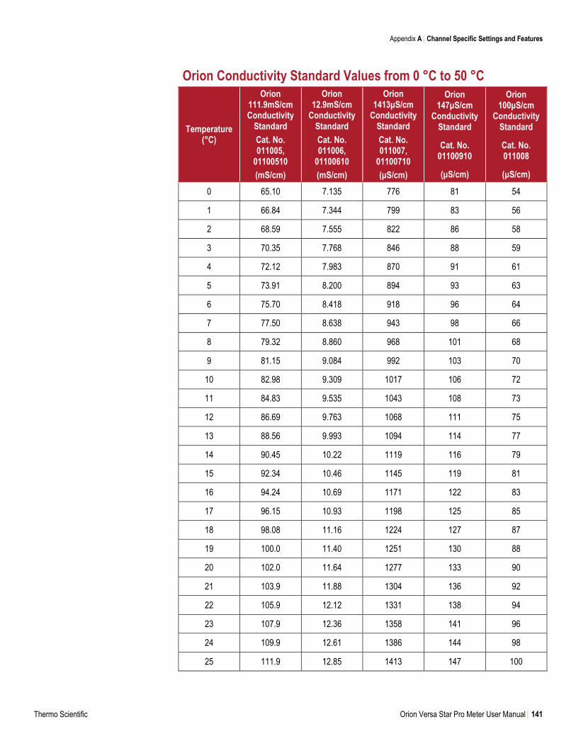
Appendix A Channel Specific Settings and Features
Thermo Scientific Orion Versa Star Pro Meter User Manual 141
Orion Conductivity Standard Values from 0 °C to 50 °C
Temperature (°C)
Orion 111.9mS/cm Conductivity
Standard
Cat. No. 011005,
01100510
(mS/cm)
Orion 12.9mS/cm
Conductivity Standard
Cat. No. 011006,
01100610
(mS/cm)
Orion 1413μS/cm
Conductivity Standard
Cat. No. 011007,
01100710
(μS/cm)
Orion 147μS/cm
Conductivity Standard
Cat. No. 01100910
(μS/cm)
Orion 100μS/cm
Conductivity Standard
Cat. No. 011008
(μS/cm)
0 65.10 7.135 776 81 54
1 66.84 7.344 799 83 56
2 68.59 7.555 822 86 58
3 70.35 7.768 846 88 59
4 72.12 7.983 870 91 61
5 73.91 8.200 894 93 63
6 75.70 8.418 918 96 64
7 77.50 8.638 943 98 66
8 79.32 8.860 968 101 68
9 81.15 9.084 992 103 70
10 82.98 9.309 1017 106 72
11 84.83 9.535 1043 108 73
12 86.69 9.763 1068 111 75
13 88.56 9.993 1094 114 77
14 90.45 10.22 1119 116 79
15 92.34 10.46 1145 119 81
16 94.24 10.69 1171 122 83
17 96.15 10.93 1198 125 85
18 98.08 11.16 1224 127 87
19 100.0 11.40 1251 130 88
20 102.0 11.64 1277 133 90
21 103.9 11.88 1304 136 92
22 105.9 12.12 1331 138 94
23 107.9 12.36 1358 141 96
24 109.9 12.61 1386 144 98
25 111.9 12.85 1413 147 100
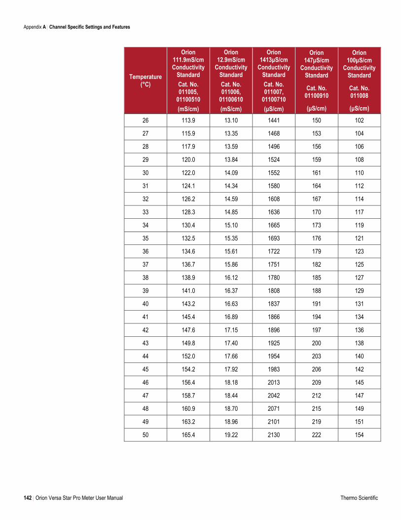
Appendix A Channel Specific Settings and Features
142 Orion Versa Star Pro Meter User Manual Thermo Scientific
Temperature (°C)
Orion 111.9mS/cm Conductivity
Standard
Cat. No. 011005,
01100510
(mS/cm)
Orion 12.9mS/cm
Conductivity Standard
Cat. No. 011006,
01100610
(mS/cm)
Orion 1413μS/cm
Conductivity Standard
Cat. No. 011007,
01100710
(μS/cm)
Orion 147μS/cm
Conductivity Standard
Cat. No. 01100910
(μS/cm)
Orion 100μS/cm
Conductivity Standard
Cat. No. 011008
(μS/cm)
26 113.9 13.10 1441 150 102
27 115.9 13.35 1468 153 104
28 117.9 13.59 1496 156 106
29 120.0 13.84 1524 159 108
30 122.0 14.09 1552 161 110
31 124.1 14.34 1580 164 112
32 126.2 14.59 1608 167 114
33 128.3 14.85 1636 170 117
34 130.4 15.10 1665 173 119
35 132.5 15.35 1693 176 121
36 134.6 15.61 1722 179 123
37 136.7 15.86 1751 182 125
38 138.9 16.12 1780 185 127
39 141.0 16.37 1808 188 129
40 143.2 16.63 1837 191 131
41 145.4 16.89 1866 194 134
42 147.6 17.15 1896 197 136
43 149.8 17.40 1925 200 138
44 152.0 17.66 1954 203 140
45 154.2 17.92 1983 206 142
46 156.4 18.18 2013 209 145
47 158.7 18.44 2042 212 147
48 160.9 18.70 2071 215 149
49 163.2 18.96 2101 219 151
50 165.4 19.22 2130 222 154
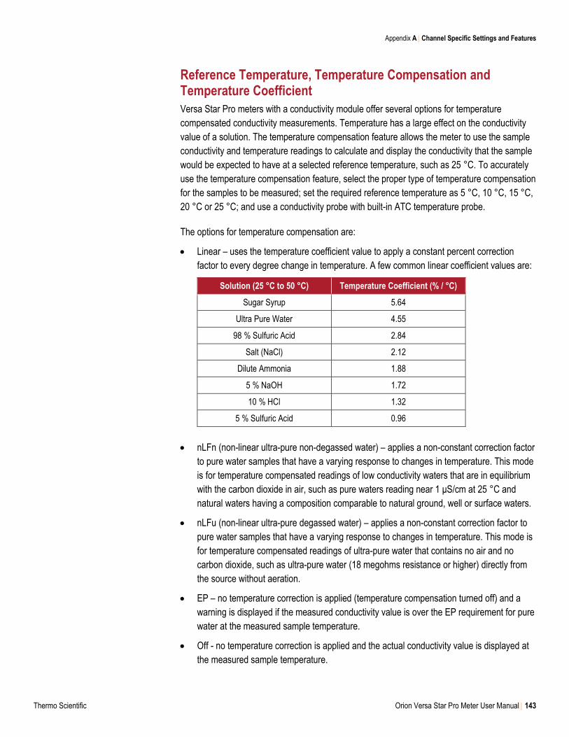
Appendix A Channel Specific Settings and Features
Thermo Scientific Orion Versa Star Pro Meter User Manual 143
Reference Temperature, Temperature Compensation and Temperature Coefficient
Versa Star Pro meters with a conductivity module offer several options for temperature
compensated conductivity measurements. Temperature has a large effect on the conductivity
value of a solution. The temperature compensation feature allows the meter to use the sample
conductivity and temperature readings to calculate and display the conductivity that the sample
would be expected to have at a selected reference temperature, such as 25 °C. To accurately
use the temperature compensation feature, select the proper type of temperature compensation
for the samples to be measured; set the required reference temperature as 5 °C, 10 °C, 15 °C,
20 °C or 25 °C; and use a conductivity probe with built-in ATC temperature probe.
The options for temperature compensation are:
Linear – uses the temperature coefficient value to apply a constant percent correction
factor to every degree change in temperature. A few common linear coefficient values are:
Solution (25 °C to 50 °C) Temperature Coefficient (% / °C)
Sugar Syrup 5.64
Ultra Pure Water 4.55
98 % Sulfuric Acid 2.84
Salt (NaCl) 2.12
Dilute Ammonia 1.88
5 % NaOH 1.72
10 % HCl 1.32
5 % Sulfuric Acid 0.96
nLFn (non-linear ultra-pure non-degassed water) – applies a non-constant correction factor
to pure water samples that have a varying response to changes in temperature. This mode
is for temperature compensated readings of low conductivity waters that are in equilibrium
with the carbon dioxide in air, such as pure waters reading near 1 μS/cm at 25 °C and
natural waters having a composition comparable to natural ground, well or surface waters.
nLFu (non-linear ultra-pure degassed water) – applies a non-constant correction factor to
pure water samples that have a varying response to changes in temperature. This mode is
for temperature compensated readings of ultra-pure water that contains no air and no
carbon dioxide, such as ultra-pure water (18 megohms resistance or higher) directly from
the source without aeration.
EP – no temperature correction is applied (temperature compensation turned off) and a
warning is displayed if the measured conductivity value is over the EP requirement for pure
water at the measured sample temperature.
Off - no temperature correction is applied and the actual conductivity value is displayed at
the measured sample temperature.
Appendix A Channel Specific Settings and Features
144 Orion Versa Star Pro Meter User Manual Thermo Scientific
Cell Type
The Versa Star Pro meter with conductivity module accepts 2-cell and 4-cell conductivity probes
and allows the type of conductivity probe to be set as Standard (most conductivity probes) or
USP (for the ultra-pure water conductivity probe, Catalog Number 013016MD, when disabling
temperature compensation).
TDS Factor
The Versa Star Pro meter with conductivity module measures TDS as the total amount of
dissolved inorganic material in a solution. The dissolved inorganic material carries a current that
is measured by the conductivity probe. Since there is a direct relationship between conductivity
and TDS, conductivity readings are used to estimate the presence of inorganic material using
the TDS factor entered in the setup menu.
The standard method of determining TDS involves evaporating a sample to dryness at 180 °C
and weighing the residue. The TDS factor is calculated by taking the residue weight and
dividing it by the sample conductivity. Subsequent conductivity readings are multiplied by the
TDS factor to determine the TDS value of the sample.
Salinity Type
The Versa Star Pro meter with conductivity module offers two salinity types: practical salinity
and natural sea water. Practical salinity measurements are based on relating the sample
measurement to the reading of a standard potassium chloride (KCl) solution at 15 °C. The
Versa Star Pro meter with conductivity module will automatically temperature compensate and
report the expected practical salinity result as practical salinity units (psu) at 15 °C when using
a conductivity probe with built-in temperature sensor. Natural sea water measurements use a
historic convention known as UNESCO 1966 and the Versa Star Pro meter with conductivity
module will report the expected natural sea water result as parts per thousand (ppt).
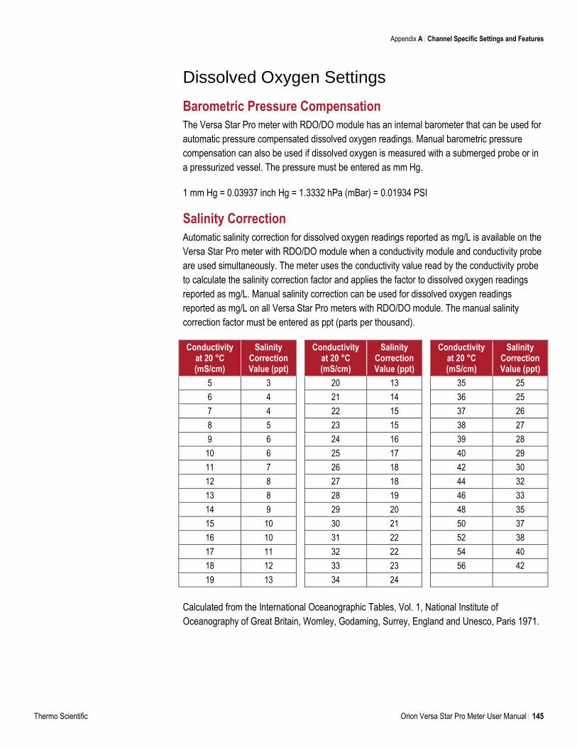
Appendix A Channel Specific Settings and Features
Thermo Scientific Orion Versa Star Pro Meter User Manual 145
Dissolved Oxygen Settings
Barometric Pressure Compensation
The Versa Star Pro meter with RDO/DO module has an internal barometer that can be used for
automatic pressure compensated dissolved oxygen readings. Manual barometric pressure
compensation can also be used if dissolved oxygen is measured with a submerged probe or in
a pressurized vessel. The pressure must be entered as mm Hg.
1 mm Hg = 0.03937 inch Hg = 1.3332 hPa (mBar) = 0.01934 PSI
Salinity Correction
Automatic salinity correction for dissolved oxygen readings reported as mg/L is available on the
Versa Star Pro meter with RDO/DO module when a conductivity module and conductivity probe
are used simultaneously. The meter uses the conductivity value read by the conductivity probe
to calculate the salinity correction factor and applies the factor to dissolved oxygen readings
reported as mg/L. Manual salinity correction can be used for dissolved oxygen readings
reported as mg/L on all Versa Star Pro meters with RDO/DO module. The manual salinity
correction factor must be entered as ppt (parts per thousand).
Conductivity at 20 °C (mS/cm)
Salinity Correction Value (ppt)
Conductivity
at 20 °C (mS/cm)
Salinity Correction Value (ppt)
Conductivity
at 20 °C (mS/cm)
Salinity Correction Value (ppt)
5 3 20 13 35 25
6 4 21 14 36 25
7 4 22 15 37 26
8 5 23 15 38 27
9 6 24 16 39 28
10 6 25 17 40 29
11 7 26 18 42 30
12 8 27 18 44 32
13 8 28 19 46 33
14 9 29 20 48 35
15 10 30 21 50 37
16 10 31 22 52 38
17 11 32 22 54 40
18 12 33 23 56 42
19 13 34 24
Calculated from the International Oceanographic Tables, Vol. 1, National Institute of
Oceanography of Great Britain, Womley, Godaming, Surrey, England and Unesco, Paris 1971.

Water and Lab Products
Australia: (613) 9757-4300 In Australia: (1300) 735-295 China: (86) 21-6865-4588
Germany: (49) 6184-90-6321 India: (91) 22-6716-2261/2247 Japan: (81) 045-453-9175
North America: 1-978-232-6000 Toll Free: 1-800-225-1480 Singapore: (65) 6778-6876
Find out more at thermofisher.com/water
For Research Use Only. Not for use in diagnostic procedures. © 2017 Thermo Fisher Scientific Inc. All rights reserved. RDO is a
registered trademark of In-Situ Inc. Microsoft, Windows and Microsoft Vista are registered trademarks of Microsoft Corporation. All
other trademarks are the property of Thermo Fisher Scientific Inc. & its subsidiaries unless otherwise specified.
68X000791 RevB 0418
Recommended