1
Overview of RF ExposureOverview of RF ExposureConcepts and RequirementsConcepts and Requirements
Kwok ChanKwok ChanTechnical Research BranchTechnical Research Branch
Federal Communications CommissionOffice of Engineering and Technology
Laboratory Division
Note: hyperlinks may not work in notes section of various slides; cut & paste links into internet browser

2
October 2005 TCB Workshop 2
RF Exposure RequirementsRF Exposure Requirements
Exposure Standards– ANSI/IEEE C95.1-1992– NCRP Report No. 86
FCC Proceedings– ET Docket 93-62
• FCC 96-326: Report & Order• FCC 96-489: 1st MO&O• FCC 97-303: 2nd MO&O
– ET Docket 03-137• FCC 03-132: NPRM
FCC Dockets - http://www.fcc.gov/oet/NCRP Report No. 86 - http://www.ncrponline.org/rpt86.htmlIEEE Standard 1528 -http://grouper.ieee.org/groups/scc34/sc2/wg1/appr_memo.html
Note: hyperlinks may not work in notes section; cut & paste above links into internet browser

3
October 2005 TCB Workshop 3
Rules & ProceduresRules & Procedures
FCC Rules: 47 CFR– Licensed & Unlicensed transmitters
• §1.1307: fixed facilities• §2.1091: mobile installations• §2.1093: portable operations
FCC documents– OET Bulletin 65: overall requirements
• Supplement A: fixed transmitters• Supplement B: amateur radio• Supplement C: mobile & portable devices
– OET Bulletin 56: consumer FAQ
The appropriate exposure limits are generally applicable to all facilities, operations and transmitters regulated by the FCC; however, some require routine evaluation to demonstrate compliance and others may be categorically excluded from routine evaluation.
CFR Link - http://ecfr.gpoaccess.gov/cgi/t/text/text-idx?&c=ecfr&tpl=/ecfrbrowse/Title47/47tab_02.tplOET Bulletins - http://www.fcc.gov/oet/rfsafety/

4
October 2005 TCB Workshop 4
Operating ConditionsOperating ConditionsFixed facilities: §1.1307 (MPE)– antennas on outdoor permanent structures
• whole body exposure in far-field conditions• broadcast towers, basestations etc.
Mobile installations: §2.1091 (MPE @ ≥ 20 cm)– antennas on non-permanent objects & structures
• partial body exposure between near to far field conditions• vehicle-mounted antennas, desktop configurations etc.
Portable operations: §2.1093 (SAR @ < 20 cm)– devices at close proximity to persons
• localized exposure in near-field conditions• wireless handsets, Wi-Fi products etc.
•Maximum permissible Exposure (MPE) according to field strength and power density limits based on whole-body SAR averaging concepts are used for evaluating the exposure conditions of fixed and mobile exposure conditions.•SAR compliance is with respect to both whole-body and partial body SAR limits.•Certain equipment and operating configurations may need different equipment classes for fixed, mobile & portable configurations that could require a new grant of equipment certification. Therefore, Class II permissive change may not be applicable in certain situations when devices are reconfigured or repackaged that result in changes in fixed, mobile or portable exposure conditions.

5
October 2005 TCB Workshop 5
Exposure ConditionsExposure Conditions
Occupational / Controlled Exposure– must be work related or transient in nature
• person must be fully aware of exposure• person must have knowledge to control & limit exposure• require RF exposure training• higher exposure limits apply
General Population / Uncontrolled Exposure– all other situations
• apply to all consumer devices• no knowledge of exposure required• more restrictive exposure limits apply
•OCCUPATIONAL / CONTROLLED EXPOSURE: In general, occupational/controlled exposure limits are applicable to situations in which persons are exposed as a consequence of their employment, who have been made fully aware of the potential for exposure and can exercise control over their exposure. This exposure category is also applicable when the exposure is of a transient nature due to incidental passage through a location where the exposure levels may be higher than the general population/uncontrolled limits, but the exposed person is fully aware of the potential for exposure and can exercise control over his or her exposure by leaving the area or by some other appropriate means. Awareness of the potential for RF exposure in a workplace or similar environment can be provided through specific training as part of a RF safety program. If appropriate, warning signs and labels can also be used to establish such awareness by providing prominent information on the risk of potential exposure and instructions on methods to minimize such exposure risks.•GENERAL POPULATION / UNCONTROLLED EXPOSURE: The general population/uncontrolled exposure limits are applicable to situations in which the general public may be exposed or in which persons who are exposed as a consequence of their employment may not be made fully aware of the potential for exposure or cannot exercise control over their exposure. Members of the general public would come under this category when exposure is not employment-related; for example, in the case of a wireless transmitter thatexposes persons in its vicinity. Warning labels placed on low-power consumer devices such as cellular telephones are not considered sufficient to allow the device to be considered under the occupational/controlled category, and the general population/uncontrolled exposure limits apply to these devices.•In certain situations both occupational/controlled and general population/uncontrolled exposure conditions may exist; therefore, compliance with both limits are necessary. For example, exposure to workers on a broadcast tower and other persons transiting near such facilities.
6
October 2005 TCB Workshop 6
Time Averaged ExposureTime Averaged ExposureOccupational / Controlled exposure conditions– any 6-minute duration for both MPE (and SAR)– operational based duty factor is acceptable
General Population / Uncontrolled exposure conditions– fixed installations
• any 30-minute duration with respect to MPE limits– mobile and portable operating conditions
• operational duty factors do not apply• source-based time-averaging is acceptable
– inherent to hardware design or transmission protocol– may include certain hardware or firmware restrictions
Note: do not confuse RF exposure duty factor with dwell time used in frequency hopping configurations; RF power generally remains on as a device hops among different frequency channels

7
October 2005 TCB Workshop 7
MPEMPE Occupational/Controlled Exposure Limits
Frequency Electric Field Magnetic Field Power Density Averaging Time Range Strength (E) Strength (H) (S) |E|2, |H|2 or S (MHz) (V/m) (A/m) (mW/cm2) (minutes)
0.3-3.0 614 1.63 (100)* 6 3.0-30 1842/f 4.89/f (900/f2)* 6 30-300 61.4 0.163 1.0 6 300-1500 -- -- f/300 6 1500-100,000 -- -- 5 6
General Population/Uncontrolled Exposure Limits Frequency Electric Field Magnetic Field Power Density Averaging Time Range Strength (E) Strength (H) (S) |E|2, |H|2 or S (MHz) (V/m) (A/m) (mW/cm2) (minutes)
0.3-1.34 614 1.63 (100)* 30 1.34-30 824/f 2.19/f (180/f2)* 30 30-300 27.5 0.073 0.2 30 300-1500 -- -- f/1500 30 1500-100,000 -- -- 1.0 30 f = frequency in MHz *Plane-wave equivalent power density
MPE limits apply to both fixed and mobile exposure conditions.Limits at 30-300 MHz are more restrictive due to possibility of whole-body resonance issues; that is, wavelength is compatible with the dimensions of persons. The limits are increased gradually through 300-1500 MHz with respect to frequency.

8
October 2005 TCB Workshop 8
SARSAROccupational/Controlled Exposure Limits (W/kg)
Whole-Body Partial-Body Hands, Wrists, Feet and Ankles
0.4 8.0 20.0
General Population/Uncontrolled Exposure Limits (W/kg)
Whole-Body Partial-Body Hands, Wrists, Feet and Ankles
0.08 1.6 4.0 Whole-Body SAR is averaged over the entire body. Partial-body SAR is averaged over any 1 g of tissue in the shape of a cube. SAR for hands, wrists, feet and ankles is averaged over any 10 g of tissue in the shape of a cube. SAR limits are not applicable above 6.0 GHz; MPE limits for field strength and power density should be applied. Categorical exclusion of routine MPE evaluation for mobile transmitters does not apply to portable devices operating above 6.0 GHz.
SAR is the basic (fundamental reference) exposure limit. Field strength and power density limits (MPE) are derived from SAR. SAR is defined in tissue media only and must be evaluated in tissue medium. MPE is defined according to free-space fields. MPE limits have included additional margins to ensure compliance with respect to SAR requirements while using simpler free-space field evaluation procedures.

9
October 2005 TCB Workshop 9
Routine EvaluationRoutine EvaluationPotentials for exposure usually vary with operating configurations & exposure conditionsPotential for exceeding limits may – require routine evaluation to demonstrate compliance– allow certain operations to be categorically excluded
from routine evaluationRoutine evaluation is required according to– Table 1 of §1.1307 for fixed facilities– §2.1091(c) for mobile operations– §2.1093(c) for portable devices
Evaluation may be triggered by §1.1307(c) or (d)
•Exposure limits apply to all FCC regulated devices & facilities, see §1.1307(b)(1)•Devices and services not identified in §§ 1.1307, 2.1091 and 2.1093 are considered categorically excludedfrom routine RF exposure evaluation to demonstrate compliance•Mobile devices are categorically excluded from routine evaluation according to §2.1091 when operating at ≤1.5 GHz and < 1.5 W ERP or > 1.5 GHz and < 3.0 W ERP•Routine evaluation for portable devices includes SAR measurement or computational modeling to show compliance for the applicable operating configurations and exposure conditions of a device, including certain accessories•Devices using computational modeling to demonstrate SAR compliance are not qualified for TCB approval, including Part 95 subpart H, MICS devices•Also see TCB Exclusion List for evaluation requirements of equipment seeking TCB approval

10
October 2005 TCB Workshop 10
RF Exposure LabelsRF Exposure LabelsLabels must be legible and clearly visible for the exposed persons to meet exposure requirementsLabels may be used to identify RF exposure training material for satisfying occupational use conditionsFor general population exposure conditions– labels generally do not substitute for routine evaluation– device should demonstrate compliance for normal
operations without use of labels– labels may apply to certain unintended and mostly
intermittent conditions of increased potential for exposure– operating instructions and caution statements should be
included in manuals to alert users about proper operation
•Labeling requirements for fixed transmitter sites and facilities can be quite different for occupational and general population exposure conditions. Workers are likely to be in areas with much higher field conditions that are not accessible by the general public.•RF exposure labeling is required for certain subscriber transceivers, see Table 1 of §1.1307

11
October 2005 TCB Workshop 11
Fixed Transmitter SitesFixed Transmitter SitesFixed transmitters operate at different frequencies may be collocated on towers and buildings etc.– exposure depends on the antenna configuration at a site– compliance is usually determined at the time of licensing
according to §1.1307(b)(3)
RF exposure labels are required for subscriber transceivers - BRS, EBS, LMDS AND DEMSCompliance for both general population and occupational limits are requiredUnlicensed PCS and NII devices must use general population limits; occupational limits do not apply
•Basestation and similar transmitter antennas are typically mounted on tower, roof-top, side of commercial buildings and similar outdoor permanent structures. Other than service personnel (authorized workers), unauthorized persons (general public) are not expected to be near the antennas of these transmitters•Transmitter licensees are (jointly) responsible for RF exposure evaluation and compliance at a particular site. License approval (to transmit) is independent of equipment certification (authorization). The applicable antennas and installation configurations are generally not detailed in the application for equipment authorization. Therefore, exposure compliance is generally not handled during equipment certification•See OET 65 (page 35) and other relevant sections for procedures on how to apply frequency dependent exposure limits•Subscriber transceivers:
•Part 27 Subpart M - Broadband Radio Service (BRS) & Educational Broadband Service (EBS): http://wireless.fcc.gov/services/brsebs/
•BRS formerly known as the Multipoint Distribution Service (MDS)/Multichannel Multipoint Distribution Service (MMDS), is a commercial service. In the past, it was generally used for the transmission of data and video programming to subscribers using high-powered systems, also known as wireless cable. However, over the years, the uses have evolved to include digital two-way systems capable of providing high-speed, high-capacity broadband service, including two-way Internet service via cellularized communication systems. Such services provide consumers integrated access to voice, high-speed data, video-on-demand, and interactive delivery services from a wireless device. •EBS formerly known as the Instructional Television Fixed Service (ITFS), is an educational service that has generally been used for the transmission of instructional material to accredited educational institutions and non-educational institutions such as hospitals, nursing homes, training centers, and rehabilitation centers using high-powered systems. Our recent revamping of the EBS spectrum will now make it possible for EBS users to continue their instructional services utilizing low-power broadband systems while also providing students with high-speed internet access.
•Part 101 Subpart L - Local Multipoint Distribution Service (LMDS)•Part 101 Subpart G - Digital Electronic Message Service (DEMS)
•The antenna of subscriber transceivers are typically built-in as an integral part of the transmitter; however, some can be detached•The RF exposure label for subscriber transceivers should
•provide adequate notice regarding potential radiofrequency safety hazards, e.g., information regarding the safe minimum separation distance required between users and transceiver antennas•references the applicable FCC-adopted limits for radiofrequency exposure specified in §1.1310
•The RF exposure label of subscriber transceivers must be on the side of the antenna where the highest exposure is expected; if necessary, multiple labels may necessary•A label at the back of an antenna is generally not acceptable, except when it is the only direction a person can approach the antenna•See section 2 of OET Bulletin 65 on aperture antennas to estimate minimum separation distance•Certain micro-basestations, repeaters, boosters etc. may operate indoors. These low power devices are typically categorically excluded. A minimum separation distance may be estimated according to procedures in OET Bulletin 65 (see above) for proper installation
12
October 2005 TCB Workshop 12
Mobile OperationsMobile OperationsMobile configurations require antennas & radiating structures to operate at ≥ 20 cm from persons during normal useRoutine evaluation is required according to §2.1091– > 1.5 W ERP @ < 1.5 GHz and > 3.0 W ERP @ ≥ 1.5 GHz
Evaluation may include– field strength and/or power density measurements– computational modeling– estimations based on certain simple & generic exposure conditions
Different time averaging requirements apply for general population and occupational exposure conditionsAdditional considerations are required for collocated transmitters that may transmit simultaneously
•Field strength and power density limits based on whole-body SAR averaging concepts are used for evaluating mobile exposure conditions•In mobile exposure conditions, the whole body may not be exposed. Mostly partial-body exposures are expected. At high power levels, depending on the separation distance, due to non-uniform field conditions inside the body some peak exposure locations could potentially exceed SAR limits. A conservative approach would be to average field strength and power density over the exposed portions or cross-sections of a person’s body to evaluate the exposure conditions.•Compliance is with respect to field strength or power density limits in Table 1 of §1.1310•See §2.1091(d)(1) on time averaging requirements for occupational exposure•See §2.1091(d)(2) on source-based time-averaging requirements for general population exposure•Based on a 20 cm separation distance and applicable power density limits, the following power densities are estimated for 1-5 W EIRP
•0.2 mW/cm2 @ 1 W EIRP; 0.4 mW/cm2 @ 2 W EIRP; 0.6 mW/cm2 @ 3 W EIRP; 0.8 mW/cm2 @ 4 W EIRP; 1.0 mW/cm2 @ 5 W EIRP
•Routine evaluation is not required for transmitters not specifically identified in §2.1091; i.e., categorically excluded.•Estimated minimum separation distances could be larger than desired. The distance must agree with the installation and operating requirements of a mobile transmitter; otherwise, MPE measurements may be used to obtain more accurate separation distances (generally smaller) according to the actual exposure conditions•Specifying a separation distance larger (other than rounding off numbers) than the required minimum separation distance could sometimes cause conflicts with the intended device/equipment installation requirements and operating configurations. It could also lead to misinterpretations on actual exposure hazards and operating requirements. Therefore, use of distances larger than the minimum separation distance required to satisfy compliance should be discouraged and avoided•Although generic equations can provide estimated separation distances at < 20 cm; however, estimates based on far-field equations are generally not applicable to near-field conditions. §2.1091(b) requires the minimum separation distance of 20 cm for mobile devices; therefore, distances less than 20 cm would disqualify the device as a mobile transmitter. •It is important to understand the applicability and limitations of RF hazard probes for MPE measurements, errors of 25-100% are typical; expect rather large measurement uncertainties. In addition, poor measurement techniques and confusions in the applicability of safety guidelines can introduce even larger errors.•RF hazard probes generally use diode detector. Output sensitivity is linear to power in square law region but linear to field strength otherwise. Compensation using squaring circuits can sometimes greatly overestimate field strength in multiple-signal environments. However, diode detectors can also underestimate field levels in high peak pulsed-signal fields. The diode detector may saturate and overestimating the actual field when transitioning from an RMS to a peak-detecting device. There are some probes that use compensation circuitry to account for the change in video resistance (impedance of the rectified probe output signal) for operating outside the square-law region.•When a probe is calibrated in uniform CW signal/field conditions, the calibration may not reflect the probe's ability to accurately assess multiple signals or pulsed signals. Diode detectors are temperature sensitive, typically about 0.05 dB per degree C; a probe calibrated at room temperature could be off by up to 1 dB when used outdoors at elevated temperatures. See section 2 of OET Bulletin 65 on how to estimate minimum separation distances. See relevant sections of OET Bulletin 65 and page 35 on how to apply frequency dependentexposure limits.•Installation instructions and user information on applicable minimum separation distance (≥ 20 cm) is generally required for most mobile configurations; except for very low power devices with substantially low (practically no) potential for exposure

13
October 2005 TCB Workshop 13
Typical Mobile ConfigurationsTypical Mobile Configurations
Vehicle-mounted antennas– occupational vs. general population exposure conditions– work-related operator vs. passengers & nearby persons
Independent and embedded consumer devices– typical desktop and similar devices– desktop and laptop (display only) computer configurations– compliance requires proper installation
Marine radios operating on various size vessels– small boats vs. large ocean liners– mobile vs. fixed configurations
•Vehicle operators in work-related situations may qualify for occupational exposure limits through proper RF exposure training; however, general population limits apply to passengers and bystanders. The exposure limits for passengers and bystanders are more restrictive; in some situations they could also be subject to higher exposure due to proximity from antennas.•A worker in an occupational exposure environment, with the necessary training, may control the transmission of a vehicle-mounted antenna and its separation distance from bystanders (by not transmitting) to ensure passenger and bystander compliance•When antennas and radiating structures are fixed-mounted on large vessels where persons are exposed in the far-field and a minimum separation distance, as estimated according to far-field conditions (see OET 65), is guaranteed by the antenna/transmitter installation and operating requirements, such configurations may be considered according to fixed-mounted procedures
14
October 2005 TCB Workshop 14
Collocated Mobile DevicesCollocated Mobile Devices
Independent without simultaneous transmissionSimultaneous or overlapping transmissions– at single or multiple frequencies– from single or multiple antennas at close proximity
Determine compliance according to §1.1307(b)(3)– apply frequency dependent MPE limits and compute the
sum of MPE ratios (MPE/MPE limit at each frequency)– include applicable source-based time-averaging– determine minimum separation boundary (≥ 20 cm)
according to output power and spatial separations among antennas
Example Multiple Tx MPE Spreadsheet
Spreadsheet is for illustration only
-45 -40 -35 -30 -25 -20 -15 -10 -5 0 5 10 15 20 25 30 35 40 45
45
39
33
27
21
15
9
3
-3
-9
-15
-21
-27
-33
-39
-45
Distance X (cm)
Dis
tanc
e Y
(cm
)
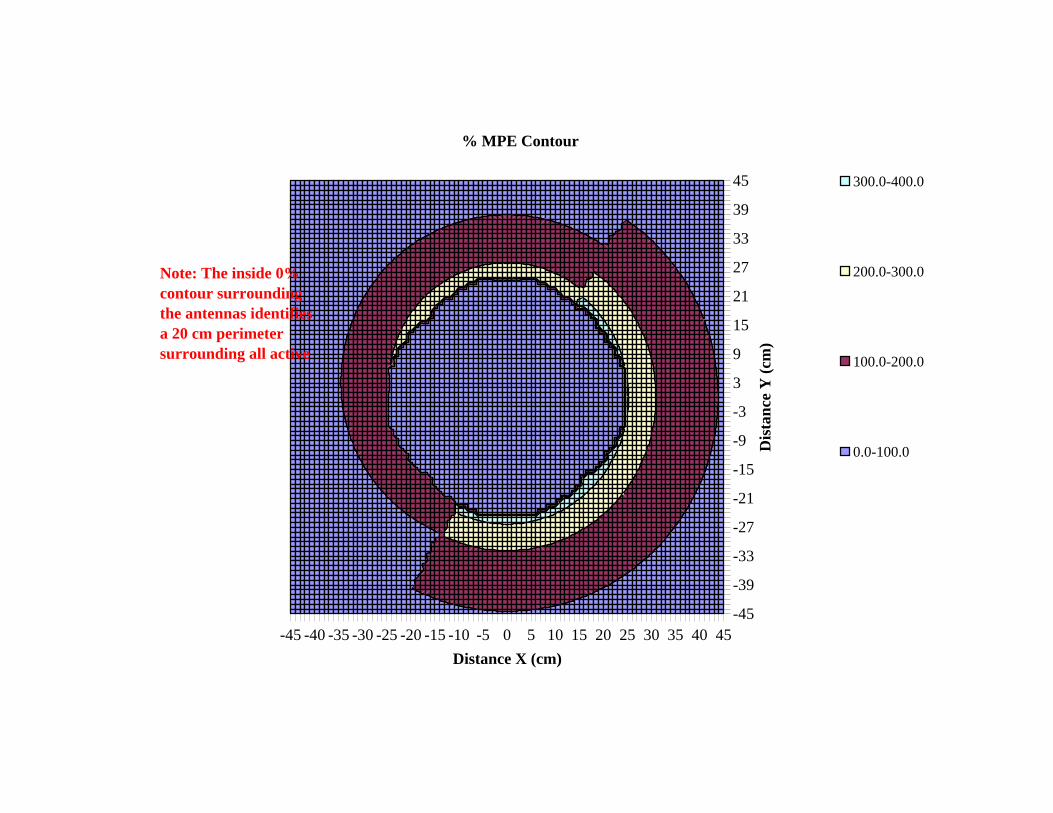
% MPE Contour
300.0-400.0
200.0-300.0
100.0-200.0
0.0-100.0
Note: The inside 0% contour surrounding the antennas identifies a 20 cm perimeter surrounding all active
t

15
October 2005 TCB Workshop 15
SAR Measurement OverviewSAR Measurement Overview
1) computer for data recording 5) ambient field2) data acquisition unit 6) phantom shell with tissue simulating liquid3) dosimetric E-field probe 7) device under test4) probe positioner 8) device positioner
A typical SAR measurement system may include: E-field probe, phantoms (head, body and planar models), field probe holder and positioner, test device holder and positioner, tissue dielectric property measurement equipment (dielectric probe/sensor, network analyzer etc.), SAR system performance verification equipment (RF signal generator, dipoles & phantom etc.), test device signal control equipment (basestation simulator).

16
October 2005 TCB Workshop 16
Field Probe ConstructionField Probe ConstructionMiniature E-field probes with 3 orthogonal dipole sensors operating with diode detectors for evaluating the SAR of low power devices|E| = (|E1|2 + |E2|2 + |E3|2) ½ = (v1/γ1 + v2/γ2 + v3/γ3)½
∆ - Beam I - Beam
Dipole Sensor High-Impedance
Lines Diode Detector
54.7 0
450
Diameter
ProbeAxis
ProtectiveSleeve
DipoleSensor
SensorOffset
ProbeTip
Dielectric Support
High-ImpedanceLines
Diode-Detector atDipole Feed-Point
•Probe output depends on:
−field polarization and direction of incidence
−local field gradients at the vicinity of a measurement point where the probe tip is located
−media dielectric properties and boundaries between probe, tissue-medium and phantom in the vicinity of the probe
−frequency, modulation and power level of the source (test device)
−interfering field sources, e.g., noise, static fields, ELF-fields, etc. from the ambient and nearby equipment
−other physical influences, e.g., temperature, humidity etc. could change probe performance
•Probes may be calibrated with or without the probe readout electronics and instrumentation (data acquisition unit)•Error sources may include:
•isotropy - axial and hemispherical•spatial resolution (due to probe dimensions)•boundary effects•detection limit and response time•readout electronics & instrumentation errors•linearity•offset
•Probe calibration procedures are described in IEEE Standard 1528:•dynamic range - 0.01 - 100 W/kg•probe tip diameter - ≤ 8.0 mm for 0.3-3.0 GHz
•Probes for 3-6 GHz are available from a few manufacturers but established SAR procedures are not available

17
October 2005 TCB Workshop 17
SAR = σ|E|2/ρ = c∆T/∆tFrequency and tissue dielectric property dependentCalibration point is at geometric center of sensors– sensors are not at probe tip and are offset from probe axis
Probe calibration procedures for 0.3-3 GHz are described in IEEE Standard 1528Probes should be calibrated in gradient fields using– temperature rise technique - < 800 MHz– waveguide technique - ≥ 800 MHz
Field Probe CalibrationField Probe Calibration
(Calibration and characterization of the probe together with the readout electronics and the post-processing system: This is preferred if the probe is uniquely used in a specific system. If the probe is calibrated with different readout electronic devices, manufacturing variations that result in differences in input characteristics from unit to unit must be considered in the uncertainty evaluation. Even though, an E-field probe is calibrated with its associated instrumentation and readout electronics, it is suggested that the probe output performance be evaluated with and without the processing and compensation system, so that the probe characteristics are known specifically.
(Calibration and characterization of the probe without the readout and post processing system, i.e., at the probe connector: The acceptable input characteristics of the readout electronics must be specified, as well as the E-field strength used during calibration and characterization. The probe can then be used in any system that matches these characteristics. Deviations in the input characteristics as well as all errors introduced by the instrumentation must be considered in the uncertainty analysis.
18
October 2005 TCB Workshop 18
IEEE Standard 1528 SAM head phantom for testing handsets next to the earFlat phantom for system validation and testing other operating configurationsPhantom shell dielectric properties, shape and dimensions are fully defined in Standard 1528Homogeneous tissue-equivalent liquids are usedTissue dielectric parameters are definedCurrently no hand phantom available
Phantom RequirementsPhantom Requirements
•SAR is measured in tissue-equivalent models coupled to the test devices (portable transmitters)•Energy coupling due to phantom shape, device positioning and tissue dielectric parameters can cause substantial SAR variations•Phantoms are filled with homogeneous tissue-equivalent liquid to simulate the composite dielectric properties of head or body•The dielectric parameters chosen for the tissue-equivalent liquid, dielectric constant and conductivity, determine the conservativeness of the SAR evaluation•Hand SAR for low-power handheld devices generally do not have compliance concerns because SAR limits for extremities are 2.5 times higher (4.0 W/kg, 10-g SAR) than the rest of the body (1.6 W/kg, 1-g SAR)
19
October 2005 TCB Workshop 19
ERP
EEC - entrance to ear canal
15 mm
M
BLE
F
ERP - ear reference point
EEC
M
B
-30
N
F+30
0
+20 0
-60
RE (ERP)
10 mm square
N
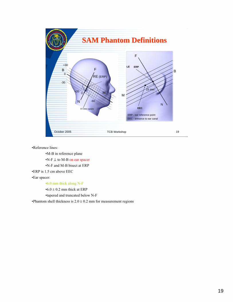
SAM Phantom DefinitionsSAM Phantom Definitions
•Reference lines:•M-B in reference plane•N-F ⊥ to M-B on ear spacer•N-F and M-B bisect at ERP
•ERP is 1.5 cm above EEC•Ear spacer:
•6.0 mm thick along N-F•6.0 ± 0.2 mm thick at ERP•tapered and truncated below N-F
•Phantom shell thickness is 2.0 ± 0.2 mm for measurement regions

20
October 2005 TCB Workshop 20
• shell thickness– bottom:
• > 800 MHz - 2.0 ± 0.2 mm with < 1% sagging (of λair)• ≤ 800 MHz - < 6.5 ± 0.2 mm with < 0.5% sagging (of λair)
– other regions: unspecified• length and width: ≥ 0.6 λ• liquid depth: 15.0 ± 0.5 cm• shell material: εr < 5.0 and loss tangent < 0.05
200 mm
Flat Phantom DefinitionsFlat Phantom Definitions
Sagging is 1.0 cm @ 300 MHz
Dimensions established according to numerical simulations done at 835 MHz for 10-g SAR

21
October 2005 TCB Workshop 21
Target Frequency Head Body (MHz) εr σ (S/m) εr σ (S/m)
150 52.3 0.76 61.9 0.80
300 45.3 0.87 58.2 0.92
450 43.5 0.87 56.7 0.94
835 41.5 0.90 55.2 0.97
900 41.5 0.97 55.0 1.05
915 41.5 0.98 55.0 1.06
1450 40.5 1.20 54.0 1.30
1610 40.3 1.29 53.8 1.40
1800 – 2000 40.0 1.40 53.3 1.52
2450 39.2 1.80 52.7 1.95
3000 38.5 2.40 52.0 2.73
5800 35.3 5.27 48.2 6.00
(εr = relative permittivity, σ = conductivity and ρ = 1000 kg/m3)
Tissue Dielectric PropertiesTissue Dielectric Properties
•IEEE Standard 1528 defines head tissue parameters for 300 MHz – 3000 MHz only. The parameters are derived based on numerical simulations using the various 4-Cole-Cole head tissue parameters•Head parameters at 150 MHz and 5800 MHz are extrapolated with respect to the slope of the 4-Cole-Cole parameters for average white and gray matters (brain). The choice of tissue parameters in a homogeneous phantom determines the amount of SAR overestimation•Tissue dielectric parameters used for SAR measurement should be within ±5% (10% when > 2.0 GHz)•The temperature of the liquid during SAR measurement should be maintained within ± 2°C of that recorded when the tissue parameters are measured•Parameters at other frequencies can be computed by linear interpolation•Body parameters are specified in Supplement C to OET Bulletin 65; adjusted according to the ratios of head & muscle tissues using the 4-Cole-Cole tissue parameters
22
October 2005 TCB Workshop 22
Tissue Property MeasurementsTissue Property Measurements
IEEE 1528 recommended procedures– liquid filled Coaxial slotted line– Coaxial probe in liquid– liquid filled TEM-Line
Sensors are connected to network analyzerdielectric constant and conductivity are calculated from reflection coefficientsmeasuring standard liquids to verify accuracy5% measurement uncertainty required
Details of tissue dielectric property measurement procedures are described in IEEE Standard 1528.10% measurement uncertainty for dielectric constant is acceptable above 2 GHz when standardized tissue recipes are not available.
23
October 2005 TCB Workshop 23
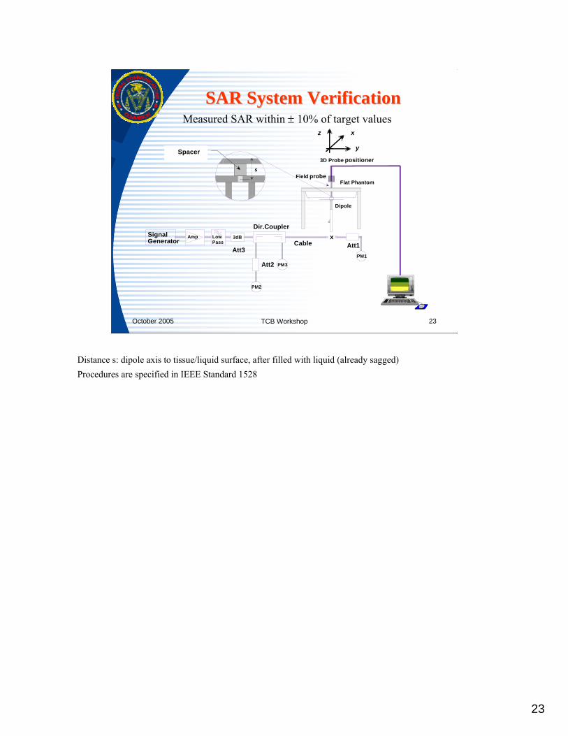
Measured SAR within ± 10% of target values
PM1
Att1x
Dipole
3D Probe positioner
Flat PhantomField probe
Signal Generator
Amp Low Pass
3dB
Att3
Dir.Coupler
Att2
PM2
Cable
PM3
s
Spacer y
z x
SAR System VerificationSAR System Verification
Distance s: dipole axis to tissue/liquid surface, after filled with liquid (already sagged)Procedures are specified in IEEE Standard 1528
24
October 2005 TCB Workshop 24
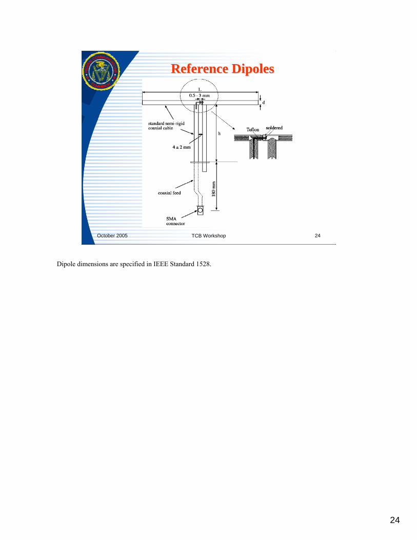
Reference DipolesReference Dipoles
Dipole dimensions are specified in IEEE Standard 1528.

25
October 2005 TCB Workshop 25
Frequency
(MHz)
1 g SAR
10 g SAR
local SAR at surface (above
feedpoint)
local SAR at surface (y=2cm
offset from feedpoint)
300 3.0 2.0 4.4 2.1 450 4.9 3.3 7.2 3.2 835 9.5 6.2 14.1 4.9 900 10.8 6.9 16.4 5.4
1450 29.0 16.0 50.2 6.5 1800 38.1 19.8 69.5 6.8 1900 39.7 20.5 72.1 6.6 2000 41.1 21.1 74.6 6.5 2450 52.4 24.0 104.2 7.7 3000 63.8 25.7 140.2 9.5
Dipole Reference SAR ValuesDipole Reference SAR Values
•Numbers are obtained by numerical simulation and experimental measurements
•Phantom sagging has not been simulated in the numerical computations
•Numbers in the last 2 column are for checking the extrapolation and interpolation procedures used in SAR systems

26
October 2005 TCB Workshop 26
Typical Test ConfigurationsTypical Test Configurations• SAR is typically tested on high, middle & low
channels• Handsets are usually tested
• on the left and right side of the SAM phantom• in cheek touching and 15º tilt positions• with antenna extended and retracted, as appropriate• tests are repeated for all operating modes and frequency
bands with certain exceptions
• Other configurations are generally tested on high, middle & low channels with the device positioned at a appropriate distance from a flat phantom
•When the measured SAR at the middle channel of each test configuration (left, right, Cheek/Touch, Tile/Ear, extended and retracted) is at least 3.0 dB lower than the SAR limit, testing at the high and low channels is optional (IEEE 1528)•If the test device has a transmission band less than 10 MHz, testing at the high and low frequency channels is optional (Supplement C)•Procedures for testing multiple modes in the same frequency band for handsets are described in IEEE 1528; also see PN DA 02-1438
27
October 2005 TCB Workshop 27
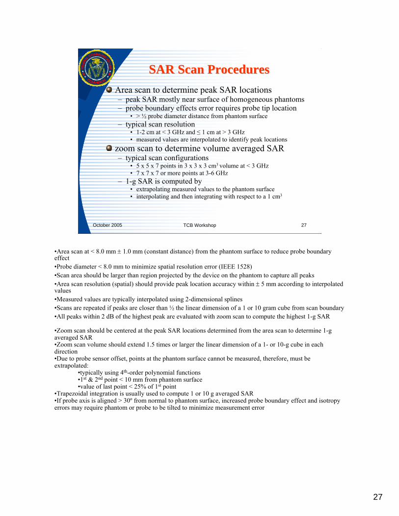
Area scan to determine peak SAR locations– peak SAR mostly near surface of homogeneous phantoms– probe boundary effects error requires probe tip location
• > ½ probe diameter distance from phantom surface– typical scan resolution
• 1-2 cm at < 3 GHz and ≤ 1 cm at > 3 GHz• measured values are interpolated to identify peak locations
zoom scan to determine volume averaged SAR– typical scan configurations
• 5 x 5 x 7 points in 3 x 3 x 3 cm3 volume at < 3 GHz• 7 x 7 x 7 or more points at 3-6 GHz
– 1-g SAR is computed by• extrapolating measured values to the phantom surface• interpolating and then integrating with respect to a 1 cm3
SAR Scan ProceduresSAR Scan Procedures
•Area scan at < 8.0 mm ± 1.0 mm (constant distance) from the phantom surface to reduce probe boundary effect•Probe diameter < 8.0 mm to minimize spatial resolution error (IEEE 1528)•Scan area should be larger than region projected by the device on the phantom to capture all peaks•Area scan resolution (spatial) should provide peak location accuracy within ± 5 mm according to interpolated values•Measured values are typically interpolated using 2-dimensional splines•Scans are repeated if peaks are closer than ½ the linear dimension of a 1 or 10 gram cube from scan boundary•All peaks within 2 dB of the highest peak are evaluated with zoom scan to compute the highest 1-g SAR
•Zoom scan should be centered at the peak SAR locations determined from the area scan to determine 1-g averaged SAR•Zoom scan volume should extend 1.5 times or larger the linear dimension of a 1- or 10-g cube in each direction•Due to probe sensor offset, points at the phantom surface cannot be measured, therefore, must be extrapolated:
•typically using 4th-order polynomial functions•1st & 2nd point < 10 mm from phantom surface•value of last point < 25% of 1st point
•Trapezoidal integration is usually used to compute 1 or 10 g averaged SAR•If probe axis is aligned > 30º from normal to phantom surface, increased probe boundary effect and isotropy errors may require phantom or probe to be tilted to minimize measurement error

28
October 2005 TCB Workshop 28
SAR Measurement UncertaintySAR Measurement Uncertainty
Identifies the probability of a measured value from its true valueStandard uncertainty of an uncertainty component– type A - statistical analysis of a series of observations
• estimating the standard deviation– type B - other than statistical analysis
• based on scientific judgement - reference data and specificationsCombined standard uncertainty– estimate the standard deviation by combining standard
uncertainties using the “root-sum-squares” methodExpanded uncertainty– multiplied the combined uncertainty by a coverage factor– defines the probability of the measured result in an interval where the
true value is believed to be
See NIST Technical Note TN 1297 (http://physics.nist.gov/Document/tn1297.pdf)

29
October 2005 TCB Workshop 29
Reporting UncertaintyReporting Uncertainty
IEEE 1528 Uc Uc Spreadsheet Template
For Information onlyFor Information only
Determine compliance according to measured SAR, if uncertainty is too large determine cause and take appropriate actions.During equipment certification, compliance is determined according to the measured values provided the expanded measurement uncertainty is less than 30% (IEEE 1528)During pre- and post-grant sample compliance tests, compliance is determined according to FCC’s measurement uncertainty.Device fails if measured value > SAR limit + FCC’s uncertainty

IEEESPECIFIC ABSORPTION RATE (SAR) IN THE HUMAN HEAD FROM WIRELESS DEVICES Std 1528-2003
Copyright © 2003 IEEE. All rights reserved. 119
Table E.4—Example of measurement uncertainty evaluation for handset SAR test
a b c de = f(d,k)
f g h =c x f / e
i = c x g /
ek
Uncertainty component Clause Tol.
(± %)Prob.Dist. Div. ci
(1 g)ci
(10 g)
1 gui
(± %)
10 gui
(± %)vi
Measurement system
Probe calibration (k = 1)
E.2.1 4.8 N 1 1 1 4.8 4.8 ∞
Axial isotropy E.2.2 4.7 R √3 (1–cp)1/2 (1–cp)1/2 1.9 1.9 ∞
Hemispherical isotropy E.2.2 9.6 R √3 √cp √cp 3.9 3.9 ∞
Boundary effect E.2.3 8.3 R √3 1 1 4.8 4.8 ∞
Linearity E.2.4 4.7 R √3 1 1 2.7 2.7 ∞
System detection limits E.2.5 1.0 R √3 1 1 0.6 0.6 ∞
Readout electronics E.2.6 1.0 N 1 1 1 1.0 1.0 ∞
Response time E.2.7 0.8 R √3 1 1 0.5 0.5 ∞
Integration time E.2.8 1.4 R √3 1 1 0.8 0.8 ∞
RF ambient conditions—noise
E.6.1 3.0 R √3 1 1 1.7 1.7 ∞
RF ambient condi-tions—reflections
E.6.1 3.0 R √3 1 1 1.7 1.7 ∞
Probe positioner mechanical tolerance
E.6.2 0.4 R √3 1 1 0.2 0.2 ∞
Probe positioning with respect to phantom shell
E.6.3 2.9 R √3 1 1 1.7 1.7 ∞
Extrapolation, interpo-lation, and integration algorithms for max. SAR evaluation
E.5 3.9 R √3 1 1 2.3 2.3 ∞
Test sample related
Test sample positioning E.4.2 6.0 N 1 1 1 6.0 6.0 11
Device holder uncer-tainty
E.4.1 5.0 N 1 1 1 5.0 5.0 7
Output power varia-tion—SAR drift mea-surement
6.6.2 5.0 R √3 1 1 2.9 2.9 ∞
Phantom and tissue parameters

IEEEStd 1528-2003 IEEE RECOMENDED PRACTICE FOR DETERMINING THE PEAK SPATIAL-AVERAGE
120 Copyright © 2003 IEEE. All rights reserved.
Phantom uncertainty (shape and thickness tolerances)
E.3.1 4.0 R √3 1 1 2.3 2.3 ∞
Liquid conductivity—deviation from target values
E.3.2 5.0 R √3 0.64 0.43 1.8 1.2 ∞
Liquid conductivity—measurement uncer-tainty
E.3.3 5.5 N 1 0.64 0.43 3.5 2.4 5
Liquid permittivity—deviation from target values
E.3.2 5.0 R √3 0.6 0.49 1.7 1.4 ∞
Liquid permittivity—measurement uncertainty
E.3.3 2.9 N 1 0.6 0.49 1.7 1.4 5
Combined standard uncertainty
RSS 13.6 13.2 158
Expanded uncertainty(95% CONFIDENCE INTERVAL)
k = 2 ± 27.2 ± 26.4
NOTE—The component values in Table E.4 are for example only and are not intended to represent the measurementuncertainty of any specific SAR test system. The measurement uncertainty for a specific handset tested with a specificSAR test system must be individually evaluated.
Table E.4—Example of measurement uncertainty evaluation for handset SAR test (continued)
a b c de = f(d,k)
f g h =c x f / e
i = c x g /
ek
Uncertainty component Clause Tol.
(± %)Prob.Dist. Div. ci
(1 g)ci
(10 g)
1 gui
(± %)
10 gui
(± %)vi
IEEESPECIFIC ABSORPTION RATE (SAR) IN THE HUMAN HEAD FROM WIRELESS DEVICES Std 1528-2003
Copyright © 2003 IEEE. All rights reserved. 121
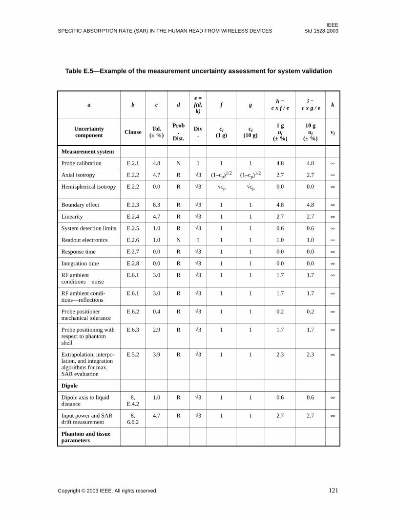
Table E.5—Example of the measurement uncertainty assessment for system validation
a b c de = f(d,k)
f g h =c x f / e
i = c x g / e k
Uncertainty component Clause Tol.
(± %)
Prob.
Dist.
Div.
ci(1 g)
ci(10 g)
1 gui
(± %)
10 gui
(± %)vi
Measurement system
Probe calibration E.2.1 4.8 N 1 1 1 4.8 4.8 ∞
Axial isotropy E.2.2 4.7 R √3 (1–cp)1/2 (1–cp)1/2 2.7 2.7 ∞
Hemispherical isotropy E.2.2 0.0 R √3 √cp √cp 0.0 0.0 ∞
Boundary effect E.2.3 8.3 R √3 1 1 4.8 4.8 ∞
Linearity E.2.4 4.7 R √3 1 1 2.7 2.7 ∞
System detection limits E.2.5 1.0 R √3 1 1 0.6 0.6 ∞
Readout electronics E.2.6 1.0 N 1 1 1 1.0 1.0 ∞
Response time E.2.7 0.0 R √3 1 1 0.0 0.0 ∞
Integration time E.2.8 0.0 R √3 1 1 0.0 0.0 ∞
RF ambient conditions—noise
E.6.1 3.0 R √3 1 1 1.7 1.7 ∞
RF ambient condi-tions—reflections
E.6.1 3.0 R √3 1 1 1.7 1.7 ∞
Probe positioner mechanical tolerance
E.6.2 0.4 R √3 1 1 0.2 0.2 ∞
Probe positioning with respect to phantom shell
E.6.3 2.9 R √3 1 1 1.7 1.7 ∞
Extrapolation, interpo-lation, and integration algorithms for max. SAR evaluation
E.5.2 3.9 R √3 1 1 2.3 2.3 ∞
Dipole
Dipole axis to liquid distance
8, E.4.2
1.0 R √3 1 1 0.6 0.6 ∞
Input power and SAR drift measurement
8, 6.6.2
4.7 R √3 1 1 2.7 2.7 ∞
Phantom and tissue parameters

IEEEStd 1528-2003 IEEE RECOMENDED PRACTICE FOR DETERMINING THE PEAK SPATIAL-AVERAGE
122 Copyright © 2003 IEEE. All rights reserved.
NOTES FOR TABLE E.4 AND TABLE E.5:
1—Column headings a–k are given for reference.2—Column heading abbreviations:
a) Tol.— tolerance in influence quantity. If ci = 1, this is a SAR tolerance.b) N, R, U—normal, rectangular, U-shaped probability distributions.c) Div.—divisor used to obtain standard uncertainty.
3—The uncertainty components indicated in these tables are based on the test procedures and protocols developed forthis standard. When test protocols and procedures vary, different uncertainty components may apply, e.g., parametersdefined for testing other phantom configurations and device positions.4—ci is the sensitivity coefficient that should be applied to convert the variability of the uncertainty component into avariability of SAR. For probe isotropy, cp = 0.5.5—See F.2.3 for discussions on degrees of freedom (vi) for standard uncertainty and effective degrees of freedom (veff)for the expanded uncertainty.6—Interim tolerance of 10% may be used for the relative permittivity of glycol-based liquids at frequencies above 2GHz.7—The measurement system and phantom and tissue parameters uncertainties of Table E.4 should be equal to the corre-sponding uncertainties of Table E.5.
Phantom uncertainty—shell thickness toler-ances)
E.3.1 4.0 R √3 1 1 2.3 2.3 ∞
Liquid conductivity—deviation from target values
E.3.2 5.0 R √3 0.64 0.43 1.8 1.2 ∞
Liquid conductivity—measurement uncer-tainty
E.3.3 5.5 N 1 0.64 0.43 3.5 2.4 5
Liquid permittivity—deviation from target values
E.3.2 5.0 R √3 0.6 0.49 1.7 1.4 ∞
Liquid permittivity—measurement uncertainty
E.3.3 2.9 N 1 0.6 0.49 1.7 1.4 5
Combined standard uncertainty
RSS 10.4 9.8 ∞
Expanded uncertainty(95% CONFIDENCE INTERVAL)
k = 2 ± 20.7 ± 19.6
NOTE—The component values in Table E.5 are for example only and are not intended to represent the measurementuncertainty of any specific SAR test system. The measurement uncertainty for a specific handset tested with a specificSAR test system must be individually evaluated.
Table E.5—Example of the measurement uncertainty assessment for system validation (continued)
a b c de = f(d,k)
f g h =c x f / e
i = c x g / e k
Uncertainty component Clause Tol.
(± %)
Prob.
Dist.
Div.
ci(1 g)
ci(10 g)
1 gui
(± %)
10 gui
(± %)vi
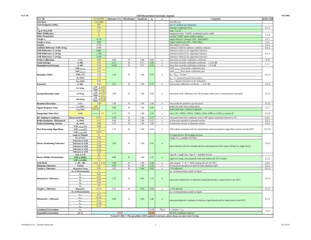
FCC ID: SAR Measurement Uncertanty Analysis 9/22/2005
Tolerance (%) Distribution Sensitivity ui νi Comment IEEE 1528mm/dd/yyyyone Uc analysis per frequencyisotropy weighting factor E.2.2enter 1 or 10integration time: "USER" modulation pulse widthinvalid "USER" pulse width or periodtarget dielectric constant (450 - 3000 MHz) 5.3.1target condictivity (450 - 3000 MHz) 5.3.1skin depth at 3.0 GHz E.2.3reference SAR for ambient condition tolerance E.6.1reference SAR (f1) for algorithm tolerancereference SAR (f2) for algorithm tolerancereference SAR (f3) for algorithm tolerance
Probe Calibration (±%) 4.85 N 1.00 4.85 ∞ from data on probe calibration certificate A.10Axial Isotropy (± dB) 4.71 R 0.71 1.92 ∞ from data on probe calibration certificate - ± 0.25 dBHemispherical Isotropy (± dB) 10.66 R 0.71 4.35 ∞ from data on probe calibration certificate - ± 0.5 dB
SAR Reference SAR Reference from probe calibration plotSAR Measured SAR Measured from probe calibration plotSARbe (%) dbe + dstep < 10 mmdbe (mm) dbe = 1st measured point from surfacedstep (mm) dstep = distance between 1st & 2nd points
Linearity (± dB) 4.71 R 1.00 2.72 ∞ from probe calibration certificate - ± 0.25 dB E.2.4CW 0.10
Pulse 0.10CW 2.10
Pulse 2.12CW 10.50
Pulse 10.40Readout Electronics (±%) 1.00 N 1.00 1.00 ∞ from probe & amplifier specifications E.2.6
t rise (ms) 5.00 probe rise time from system specst hold (ms) 500.00 probe hold time; Column D ignored
RF Ambient Conditions Measured (W/kg) 3.00 R 1.00 1.73 ∞ measured under test conditions with no RF signal, maximum allowed is 3% E.6.1Probe Positioner: Mechanical dss (mm) 0.43 R 1.00 0.25 ∞ in directions parallel to phantom surface E.6.2Probe Positioning: Surface dph (mm) 2.87 R 1.00 1.66 ∞ in directions normal to phantom surface E.6.3
SAR evaluated (f1)SAR evaluated (f2)SAR evaluated (f3)
Single or Multiple S=single device, M=multiple devicesNo. of Tests single=N-1, multiple=(N*M)-1
Tolerance or SARTolerance or SARTolerance or SARTolerance or SARTolerance or SAR
Type A or B Type B = single test, Type A = multiple devicesSAR w/ holderSAR w/o holder
SAR Drift (+ dB / -dB) 0.24 -0.20 5.68 R 1.00 3.28 ∞ enter largest "+" & "-" drifts among all tests for DUT 6.6.3Phantom Tolerance d (mm) 4.04 R 1.00 2.33 ∞ d=maximum deviation of inner & outer phantom shell E.3.1Target σ Tolerance Measued σ (S/m) 2.22 R 0.64 0.82 ∞ ± 5% allowed E.3.3
No. of Measurements no. of measurements made on liquidσ1
σ2
σ3
σ4
σ5
Target εr Tolerance Measued εr 0.12 R 0.60 0.04 ∞ ± 5% allowed E.3.3No. of Measurements no. of measurements made on liquid
εr1
εr2
εr3
εr4
εr5
Combined Uncertainty uc 11.08 782.4 νi column = νeff
Expanded Uncertainty (k=2) 22.15 94.55% confidence interval
9.09 R 1.00 5.25
SAR Reference: f3 (W/kg)
∞Integration Time (Sec) GSM 0.5 1.73 R
3.70
1.00
E.2.5maximum SAR difference for CW & pulse, either user or manufacturer measured
Signal Response Time R 1.00 ∞ E.2.7
1.00
0.00 0.00
SAR Reference: f2 (W/kg)
4.85
R 1.00
Boundary Effect 1.03 R
1.00
0.200.44
E.2.8
E.2.2
E.2.3
System Detection Limit
0.1 W/kg
2.0 W/kg
10.0 W/kg
∞
∞1.00
1.00 enter CW, AMPS, CDMA, TDMA, GSM, GPRS or USER in column B
0.59
0.58
2.000.20
Target εr
Target σ (S/m)
Ambient Reference SAR (W/kg)SAR Reference: f1 (W/kg)
δ (mm)
1.001.021.50
FCC ID ZYX0298A
1-g or 10-g SAR 1.0
7/23/20048350.50
Test DateTest Frequency (MHz)cp
E.5.1
E.2.8
3.049
13.95
41.500.90
0.4000.8811.796
3.015
0.0120.120.80
1.12 1.00R
Pulse Width (ms)Pulse Period (ms)
00
Post-Processing Algorithms0.881.8 0.64 ∞ SAR values evaluated with the interpolation and extrapolation algorithms used to test the DUT E.5.2.2
Device Positioning Tolerance1.11.171.151.111.12
S5.00
2.92 N 1.00 2.92
1.21.1
Device Holder PerturbationB
E.4.2
E.4.1
4enter tolerance (%) for multiple devices and measured SAR values (W/kg) for single device
sngle test using a flat phantom with and without the DUT holder∞
Measured σ Tolerance
5
41.4641.47
Measured εr Tolerance
0.920.910.930.95
41.55
E.3.3
5
4.00 N 0.60 2.40 4 E.3.3
41.5
0.9
0.20.92
4N 0.641.92 1.23
Version 02-2003-1: This spreadsheet will be updated as necessary, please always use most recent Version.PASS
F.2.3
measured dielectric constant of reference liquid (preferred) or liquid used to test DUT41.4241.4
measured conductivity of reference liquid (preferred) or liquid used to test DUT
Worksheet in KC - Exposure Basics.ppt 1 Ver: 02-03

30
October 2005 TCB Workshop 30
Simultaneous TransmissionSimultaneous Transmission
SAR measurements are frequency dependent due to– probe calibration requirements– tissue dielectric parameters
Simultaneous transmission at multiple frequencies requires SAR to be evaluated independently for each frequency using appropriate probe calibration and tissue dielectric parameters in identical device positioning conditions; i.e. measurement registrationThe results can be summed grid by grid according to the same measurement scan setup, followed by interpolation and extrapolation to compute 1-g SAR
•Standardized SAR measurement procedures for simultaneous transmission at multiple frequencies are current being developed by the IEC 62209-2•The draft procedures have been implemented by some SAR system manufacturers

31
October 2005 TCB Workshop 31
TCB Exclusion ListTCB Exclusion List
TCB Exclusion List
For Information only,For Information only,details are discussed separatelydetails are discussed separately
•The thresholds are for purpose of TCB approval only•TCB approval of portable devices under occupational SAR requirements is limited to PTTs only

Appendix A: TCB Exclusions List Revised: 17 July 2002
1 of 1
Transmitters included in a TCB Scope and identified in the following do not qualify for TCB approval.1 Review & Approval procedures are described in a separate document that will be revised as evaluation and approval procedures are updated.
Transmitter Category
Exclusions List
I) All Transmitters
a) devices not evaluated according to most recent versions of FCC OET 65 Supplement C or other applicable FCC policies, procedures, and TCB training notes
b) applications for equipment approval or permissive change requiring any change in equipment class (e.g., TNB to TNE, etc.) or change in RF exposure limits or exposure category
c) devices employing numerical simulation or computational modeling techniques to show RF exposure compliance
d) transmitters operating in non-US protocols or radio services (e.g., PHS, etc.) II) Portable
Transmitters a) devices with operating frequencies above 6 GHz b) devices in standalone configurations with output power2 greater than the high threshold3 c) transmitters that are implanted or operated within a person’s body d) devices operating according to occupational exposure requirements, except for push-to-talk radios e) devices containing multiple transmitters that transmit simultaneously, when routine SAR evaluation4
is required for the highest output (dominant) transmitter, and any of the other (non-dominant) transmitters is operating at higher than 5 mW
f) devices containing multiple transmitters with simultaneous transmission, when routine SAR evaluation is not required, and the sum of the individual ratios of the output power divided by the high threshold is greater than one (1)
g) modules for operation in licensed services that are not configured in a dedicated host device h) unlicensed modules used alone or with another transmitter
1) without simultaneous transmission, and the output power of any transmitter is greater than 100 mW with operating frequency less than or equal to 3 GHz, or 50 mW with frequency greater than 3 GHz but less than or equal to 6 GHz
2) with simultaneous transmission, and the sum of the individual ratios of the output power divided by the low threshold3 is greater than one (1)
1 Each TCB location must have a least one person on staff who has completed the Part 22 Subpart H and Part 24 Subpart E
handset SAR training, and the fixed, mobile, and portable transmitters RF exposure procedures training. Additional training will be provided in the future on requirements for new procedures and technology. Training workshops will be repeated as necessary to accommodate new TCBs.
2 Output power for portable transmitters is the higher of the conducted or radiated (EIRP) source-based time-averaged output. 3 In the following table, fGHz is mid-band frequency in GHz, and d is the distance to a person’s body, excluding hands, wrists,
feet, and ankles.
Exposure category low threshold high threshold
general population (60/fGHz) mW, d < 2.5 cm
(120/fGHz) mW, d ≥ 2.5 cm (900/fGHz) mW, d < 20 cm
occupational (375/fGHz) mW, d < 2.5 cm
(900/fGHz) mW, d ≥ 2.5 cm (2250/fGHz) mW, d < 20 cm
4 Routine SAR evaluation refers to that specifically required by § 2.1093, using measurements or computer simulation. When
routine SAR evaluation is not required, portable transmitters with output power greater than the applicable low threshold require SAR evaluation to qualify for TCB approval.

32
October 2005 TCB Workshop 32
TCB RF Exposure QualificationTCB RF Exposure Qualification
TCB training on SAR and general RF exposure procedures required to qualify for RF exposure scopeTraining material may include:– information and videos available for previous trainings– Supplement C, IEEE Standard 1528 and other related standards– summary and updates provided in current workshop– all other necessary updates on FCC rules, administrative
policies and equipment certification procedures available from the FCC (knowledge database) and through the TCB council
Attend additional trainings in future workshops on updates and new procedures to maintain qualification
•TCB training on SAR measurement for Part 22 & Part 24 handsets•TCB training on general exposure requirements for fixed, mobile and portable transmitters

33
October 2005 TCB Workshop 33
Other ConsiderationsOther Considerations
Modular approval of unlicensed transmitters– see Public Notice DA 00-1407
3-6 GHz SAR requirements - pendingDigital technology – Wi-Fi, Wi-Max, 3-G protocolsPermissive Change requirements: Class I, II, IIIApplying meaningful and acceptable grant comments and conditionsPending proceedings – ET Docket 03-137– fixed transmitters– mobile and portable modules (§§ 15.247 and 15.407)
•Modules may not have clearly defined operating configurations and exposure conditions; usually dependent on host configurations•3-6 GHz SAR measurement standard is not available (only working drafts), measurement difficulties are introduced by the much smaller penetration depth in tissue media•New digital technologies have complex transmission and communication protocols involving multiple modulations, data rates and dynamic conditions that introduce additional difficulties in configuring a test device to operate in stable conditions for testing•Permissive change requirements may involve various administrative, EMC and SAR considerations
Recommended