ALTERNATORS
Overview
IntekTM V-Twin Cylinder OHV Engine Service Manual
Version 1.0Copyright© 1999 by Briggs and Stratton Corporation
Page 1 of 1

ALTERNATORS
Alternator Identification
IntekTM V-Twin Cylinder OHV Engine Service Manual
Version 1.0Copyright© 1999 by Briggs and Stratton Corporation
Page 1 of 3
The alternator systems installed on Briggs & Stratton Intek V-Twin Cylinder OHV Engines can easily be identified by the
color of the stator output wires and the connector.
Table No. 1 provides a means of identifying the various alternator systems. Note: All output figures are rated at 3600 RPM.
ALTERNATOR
TYPE
STATOR OUTPUT
WIRE(S) COLOR
CONNECTO
R COLOR
AC Only Black 14 Volts AC (Lights)
Unregulated
DC OnlyRed
FIG.
1
2
3
White
White
ALTERNATOR OUTPUT
(at 3600 RPM)
2-4 Amps +DC (Charging)
Unregulated
Dual Circuit Red
Black
White
2-4 Amps +DC (Charging)
Unregulated
14 Volts AC (Lights)
Unregulated
Tri-Circuit Black4 Green 5 Amps +DC (Charging)
5 Amps -DC (Lights)
5 Amp
Regulated
Black5 Green *1 - 5 Amps +DC (Charging)
Regulated
9 Amp
Regulated
Black5 Green *1 - 9 Amps +DC (Charging)
Regulated
10 Amp
Regulated
2-Black6 Yellow *1 - 10 Amps +DC
(Charging)
Regulated16 Amp
Regulated
2-Black6 Yellow *1 - 16 Amps +DC (Charging)
Regulated

14 Volts AC for lighting circuit.
One black lead from stator.
White connector output lead.
3 amp DC unregulated for charging battery.
One red lead from stator.
Diode encased at connector.
Red connector output lead.
3 amp DC unregulated for charging battery (ONE red
lead from stator).
14 Volts AC for lighting circuit.
Diode encased at connector.
White connector with two pin terminals.
ALTERNATORS
Alternator Identification
IntekTM V-Twin Cylinder OHV Engine Service Manual
Version 1.0Copyright© 1999 by Briggs and Stratton Corporation
Page 2 of 3
Fig. 2 - DC Only Stator
Fig. 3 - Dual Circuit Stator
Fig. 1 - AC Only Stator

10 amp AC.
One black lead from stator.
Green connector.
Two diodes encased in wire harness.
Red and white output leads.
5 or 9 amp DC+ regulated for charging battery.
Alternator output (5 or 9 amp) is determined by flywheel
alternator magnet size.
Uses same stator as Tri-Circuit system.
One black lead from stator.
Green connector.
10 or 16 amp DC regulated for charging battery.
Two black leads from stator.
Yellow connector with two pin terminals.
Two yellow leads to regulator/rectifier.
One red lead from regulator/rectifier to red connector
output lead.
10 and 16 amp system use the same stator, color
coding and regulator/rectifier.
Alternator output is determined by the flywheel
alternator magnet size.
ALTERNATORS
Alternator Identification
IntekTM V-Twin Cylinder OHV Engine Service Manual
Version 1.0Copyright© 1999 by Briggs and Stratton Corporation
Page 3 of 3
Fig. 5 - 5 or 9 Amp Regulated Stator
Fig. 6 - 10 or 16 Amp Regulated Stator
Fig. 4 - Tri-Circuit Stator
Intek OHV-Twin Cylinder Flywheels have a single ring
of magnets which provide the magnetic field for the
various alternator systems. There are two (2) sizes of
alternator magnets. The size of the magnet determines
the alternator output Fig. 7.
Small Magnet 22 mm x 17 mm (7/8 x 21/32)
Large Magnet 22 mm x 23 mm (7/8 x 29/32)
Table 2 identifies the magnet size to be used with a
specific alternator system.
Note: Large magnet flywheels cannot be used with
the AC only, DC only, Dual Circuit and Tri-Circuit
alternator systems.
ALTERNATORS
Flywheel Identification
IntekTM
V-Twin Cylinder OHV Engine Service Manual
Version 1.0Copyright© 1999 by Briggs and Stratton Corporation
Page 1 of 1
Fig. 7 - Alternator Magnets
AlternatorSmall
Magnet
Large
Magnet
AC Only
DC Only
Dual Circuit
Tri-Circuit
Regulated 5 Amp
Regulated 9 Amp
∗∗∗∗
∗∗∗∗
∗∗∗∗
∗∗∗∗
Regulated 10 Amp
Regulated 16 Amp
∗∗∗∗
∗∗∗∗
∗∗∗∗
∗∗∗∗

The following list is provided to aid you in diagnosing
problems with alternator systems.
ALTERNATORS
Troubleshooting
IntekTM
V-Twin Cylinder OHV Engine Service Manual
Version 1.0Copyright© 1999 by Briggs and Stratton Corporation
Page 1 of 1
Cyl. #1
Engine #1
Engine #2
Cyl. #2
65 Psi
75 Psi 55 Psi 20 Psi 26.7%
60 Psi 60 Psi 7.6%
Psi Diff. %Diff.
COMPLAINT
∗ ∗ ∗ ∗ Engine RPM too low
∗ ∗ ∗ ∗ Inline fuse "blown" (if equipped)
∗ ∗ ∗ ∗ Defective battery
∗ ∗ ∗ ∗ Loose, pinched or corroded battery ground leads
∗ ∗ ∗ ∗ Loose, pinched or corroded battery charge leads
∗ ∗ ∗ ∗ Open, shorted or grounded wires between output conn. and battery
∗ ∗ ∗ ∗ Defective diode (open or closed)
∗ ∗ ∗ ∗ Defective or improperly grounded regulator/rectifier
∗ ∗ ∗ ∗ Diode installed incorrectly (reversed)
∗ ∗ ∗ ∗ Damaged battery (shorted battery cells)
∗ ∗ ∗ ∗ Excessive current draw from accessories
∗ ∗ ∗ ∗ Low magnetic flux or damaged alternator magnets
"Battery not charging"
POSSIBLE CAUSES
∗ ∗ ∗ ∗ Engine RPM too low
∗ ∗ ∗ ∗ Severe battery vibration (missing or broken tie-down straps)
∗ ∗ ∗ ∗ Battery amp/hour rating not matched to alternator output
∗ ∗ ∗ ∗ Damaged battery (shorted battery cells)
∗ ∗ ∗ ∗ Defective regulator/rectifier
∗ ∗ ∗ ∗ 1 Ohm resistor shorted or grounded (Tri-Circuit system only)
"Battery overcharging"
∗ ∗ ∗ ∗ Inline fuse "blown" (if equipped)
∗ ∗ ∗ ∗ Defective headlamps
∗ ∗ ∗ ∗ Loose or corroded wires
∗ ∗ ∗ ∗ Open, shorted or grounded wires between output conn. and lamps
∗ ∗ ∗ ∗ Defective headlamp switch
∗ ∗ ∗ ∗ Defective diode harness (Tri-Circuit)
∗ ∗ ∗ ∗ Low magnetic flux or damaged alternator magnets
"Headlamps not working"
∗ ∗ ∗ ∗ Inline fuse "blown" (if equipped)
∗ ∗ ∗ ∗ Loose or corroded wires
∗ ∗ ∗ ∗ Open, shorted or grounded wires between output conn. and clutch
∗ ∗ ∗ ∗ Defective diode harness (Tri-Circuit) Note: battery will not charge
∗ ∗ ∗ ∗ Defective PTO clutch switch
∗ ∗ ∗ ∗ Open, shorted PTO clutch circuit
∗ ∗ ∗ ∗ Low magnetic flux or damaged alternator magnets
"Electric PTO clutch
not working"

The following equipment is recommended to test and
repair alternators.
The Digital Multimeter is available from your Briggs &
Stratton source of supply. Order as Tool #19357 or
#19390. The meter may be used to read volts, ohms
or amperes, and test diodes, when leads are
inserted in the appropriate receptacle, Fig. 8
The Digital Multimeter will withstand DC input of 10-20
amps for up to 30 seconds. When checking DC
output on 16 and 20 amp regulated system, use the
DC shunt, Tool #19359, to avoid blowing fuse in
meter, Fig. 9.
Note: The Digital Multimeter is equipped with
two fuses to prevent damage to the meter in
the event that the input limits are exceeded. If
the meter displays a reading of 0.00 when
testing DC output (A ), check fuses in
meter.
Refer to FLUKE Operators Manual for procedure for
checking fuses. Replacement fuse is available from
your Briggs & Stratton source of supply. Order Part
No. 19449.
ALTERNATORS
Test Equipment
IntekTM V-Twin Cylinder OHV Engine Service Manual
Version 1.0Copyright© 1999 by Briggs and Stratton Corporation
Page 1 of 1
Fig. 8 - Digital Multimeter
Fig. 9 - DC Shunt - Tool # 19359

ALTERNATORS
Alternator Output Testing
IntekTM
V-Twin Cylinder OHV Engine Service Manual
Version 1.0Copyright© 1999 by Briggs and Stratton Corporation
Page 1 of 1
When checking alternators, make the tests in the following sequence.
1. Test alternator AC Volts output.
2. Test DC Amps output. Test diode(s) or regulator, rectifier (if equipped).
Note: Before testing the alternators output (volts, amps), first use an accurate tachometer and temporarily adjust the
engine speed to 3600 RPM.
WARNING: UPON COMPLETION of the alternator output test, always readjust the engine rpm to its correct top
no-load governed speed! Otherwise engine may exceed safe operating speed which could cause
personal injury.
Correct speed is found in the Service Engine Sales Manual Microfiche, MS6225 or the Service Sales Manual, MS4052.

ALTERNATORS
AC Only Alternator
IntekTM
V-Twin Cylinder OHV Engine Service Manual
Version 1.0Copyright© 1999 by Briggs and Stratton Corporation
Page 1 of 1
The AC alternator provides current for headlights only. Current for the lights is available as long as the engine is running. The
output depends upon engine speed. 12 volt lights with a total rating of 60 to 100 watts may be used. With lights rated at 70
watts, the voltage rises from 8 volts at 2400 RPM to 12 volts at 3600 RPM, so the brightness of the light changes with the
engine speed.
Fig. 1 - AC Only Stator

1. Insert RED test lead into V receptacle in meter.
2. Insert BLACK test lead into receptacle in
meter.
3. Rotate selector to V ~ (AC volts) position.
4. Attach RED test lead clip to AC output terminal,
Fig. 10.
5. Attach BLACK test lead clip to engine ground.
6. With engine running at 3600 RPM, AC output should
be no less than 14 volts.
7. If no or low output is found, replace the stator.
ALTERNATORS
AC Only Alternator
AC Output Test
IntekTM V-Twin Cylinder OHV Engine Service Manual
Version 1.0Copyright© 1999 by Briggs and Stratton Corporation
Page 1 of 1
Fig. 10 - Test AC Output

ALTERNATORS
DC Only Alternator
IntekTM V-Twin Cylinder OHV Engine Service Manual
Version 1.0Copyright© 1999 by Briggs and Stratton Corporation
Page 1 of 1
The DC alternator provides DC current for charging a 12 volt battery. The current from the alternator is unregulated and is
rated at 3 amps. The output rises from 2 amps at 2400 RPM, to 3 amps at 3600 RPM.
Recommended battery sizes range from 30 ampere hour for warm temperature service to 50 ampere hour in coldest service.
When checking alternator components, make the test in the following sequence:
Fig. 2 - DC Only Stator

1. Insert RED test lead into 10 A receptacle in meter.
2. Insert BLACK test lead into receptacle in
meter.
3. Rotate selector to (DC amps) position.
4. Attach RED test lead clip to DC output terminal, Fig. 11.
5. Attach BLACK test lead clip to positive (+) battery
terminal.
6. With engine running at 3600 RPM, output should be
between 24 amps DC.
a. Output will vary with battery voltage. If battery
voltage is at its maximum, output will be
approximately 2 amps.
7. If no or low output is found, test diode.
ALTERNATORS
DC Only Alternator
Alternator Output Test
IntekTM V-Twin Cylinder OHV Engine Service Manual
Version 1.0Copyright© 1999 by Briggs and Stratton Corporation
Page 1 of 1
Fig. 11 - Test DC Output
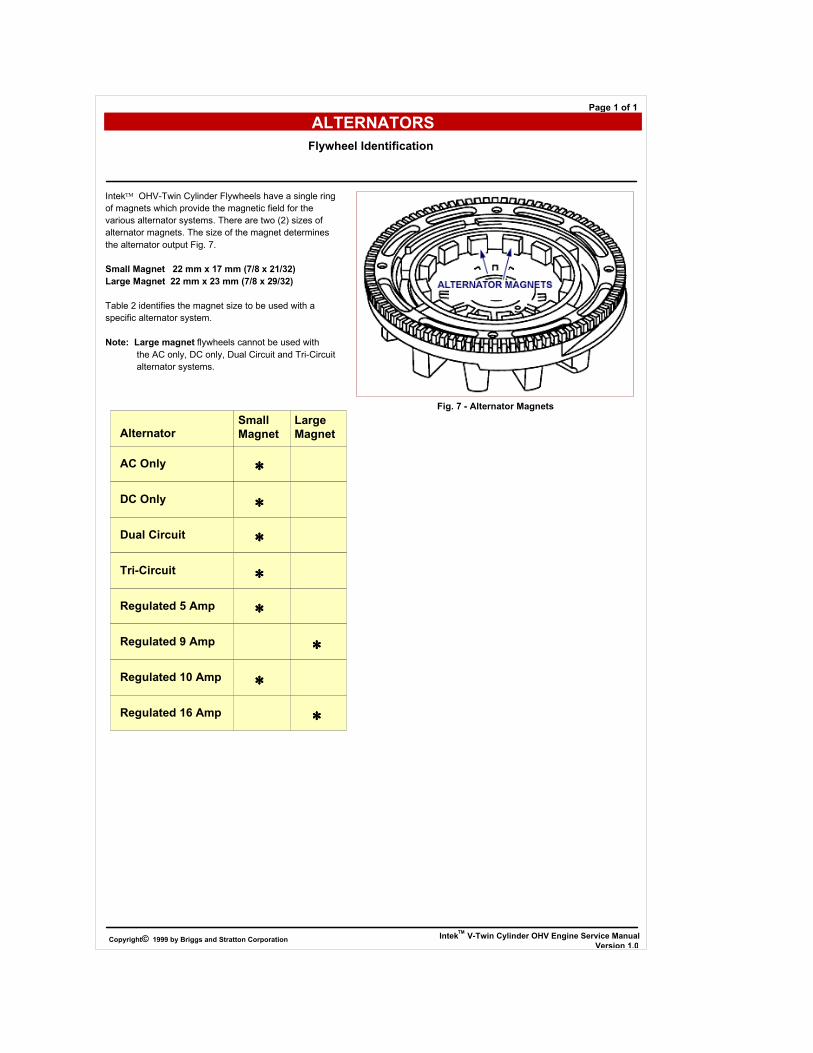
In the Diode Test position, the meter will display the
forward voltage drop across the diode(s). If the voltage
drop is less than 0.7 volts, the meter will Beep once as
well as display the voltage drop. A continuous tone
indicates continuity (shorted diode). An incomplete
circuit (open diode) will be displayed as "OL".
1. Insert RED test lead into V receptacle in meter.
2. Insert BLACK test lead into receptacle in
meter.
3. Rotate selector to (Diode Test) position.
4. Attach RED test lead clip to point "A" and BLACK test
lead clip to point "B", Fig. 12. (It may be necessary to
pierce wire with a pin as shown.)
a. If meter "Beeps" once, diode is OK.
b. If meter makes a continuous tone, diode is defective
(shorted). Replace diode.
c. If meter displays "OL", proceed to step 5.
5. Reverse test leads.
a. If meter "Beeps" once, diode is installed
backwards. Replace diode.
b. If meter still displays "OL", diode is defective
(open). Replace diode.
6. If diode tests OK, check stator for bare wires or other
obvious defects. If grounded leads are not visible,
replace the stator.
Note: Service replacement diode harnesses are
available.
Use Resin Core solder when installing new harness.
Use shrink tubing or tape all connections.
Note: Do not use crimp connectors.
ALTERNATORS
DC Only Alternator
Diode Test
IntekTM
V-Twin Cylinder OHV Engine Service Manual
Version 1.0Copyright© 1999 by Briggs and Stratton Corporation
Page 1 of 1
Fig. 12 - Test Diode

ALTERNATORS
Dual Circuit Alternator
IntekTM
V-Twin Cylinder OHV Engine Service Manual
Version 1.0Copyright© 1999 by Briggs and Stratton Corporation
Page 1 of 1
Dual circuit alternators use a single polarized plug with two pins. One pin is for charging the battery and the second is for the
AC light circuit.
The dual circuit alternator provides DC current for battery charging and an independent AC circuit for headlights. The battery
is not used for lights, so lights are available even if battery is disconnected or removed.
Current for lights is available as long as the engine is running. The output depends upon engine speed, so brightness of the
lights changes with engine speed. 12 volt lights with a total rating of 60 to 100 watts may be used. With lights rated at 70
watts, the voltage rises from 8 volts at 2400 RPM to 12 volts at 3600 RPM.
The current from the DC side of the alternator is unregulated and is rated at 3 amps. The output rises from 2 amps at 2400
RPM to 3 amps at 3600 RPM.
Fig. 3 - Dual Circuit Stator

1. Insert RED test lead into 10 A receptacle in meter.
2. Insert BLACK test lead into receptacle in
meter.
3. Rotate selector to A (DC amps) position.
4. Attach RED test lead clip to DC output pin in
connector, Fig. 13.
5. Attach BLACK test lead clip to positive (+) battery
terminal.
6. With engine running at 3600 RPM output should be
between 24 amps DC.
a. Output will vary with battery voltage. If battery
voltage is at its maximum, output will be
approximately 2 amps.
7. If no output or low output is found, test diode.
ALTERNATORS
Dual Circuit Alternator
Alternator Output Test
IntekTM V-Twin Cylinder OHV Engine Service Manual
Version 1.0Copyright© 1999 by Briggs and Stratton Corporation
Page 1 of 1
Fig. 13 - Test DC Output

In the Diode Test position, the meter will display the
forward voltage drop across the diode(s). If the voltage
drop is less than 0.7 volts, the meter will Beep once as
well as display the voltage drop. A continuous tone
indicates continuity (shorted diode) An incomplete circuit
(open diode) will be displayed as "OL".
1.Insert RED test lead into V receptacle in meter.
2. Insert BLACK test lead into receptacle in
meter.
3. Rotate selector to (Diode Test) position.
4. Attach RED test lead clip to point "A" and BLACK test
lead clip to point "B", Fig. 14. (It may be necessary to
pierce wire with a pin as shown.)
a. If meter "Beeps" once, diode is OK.
b. If meter makes a continuous tone, diode is defective
(shorted). Replace diode.
c. If meter displays "OL", proceed to step 5.
5. Reverse test leads.
a. If meter "Beeps" once, diode is installed
backwards. Replace diode.
b. If meter still displays "OL", diode is defective
(open). Replace diode.
6. If diode tests OK, check stator for bare wires or other
obvious defects. If grounded leads are not visible,
replace the stator.
Note: Service replacement diode harnessers are
available.
Use Resin Core solder when installing new harness.
Use shrink tubing or tape all connections.
Note: Do not use crimp connectors
ALTERNATORS
Dual Circuit Alternator
Diode Test
IntekTM
V-Twin Cylinder OHV Engine Service Manual
Version 1.0Copyright© 1999 by Briggs and Stratton Corporation
Page 1 of 1
Fig. 14 - Test Diode

1. Insert RED test lead into V receptacle in meter.
2. Insert BLACK test lead into receptacle in
meter.
3. Rotate selector to V ~ (AC volts) position.
4. Attach RED test lead clip to AC output terminal,
Fig. 15.
5. Attach BLACK test lead clip to engine ground.
6. With engine running at 3600 RPM output should be no
less than 14 volts AC.
7. If no output or low output is found, replace stator.
ALTERNATORS
Dual Circuit Alternator
AC Output Test
IntekTM V-Twin Cylinder OHV Engine Service Manual
Version 1.0Copyright© 1999 by Briggs and Stratton Corporation
Page 1 of 1
Fig. 15 - Test AC Output

ALTERNATORS
Tri-Circuit Alternator
IntekTM
V-Twin Cylinder OHV Engine Service Manual
Version 1.0Copyright© 1999 by Briggs and Stratton Corporation
Page 1 of 1
The tri-circuit alternator provides alternating current through a single output lead and connector to a wiring harness
containing two diodes.
One diode rectifies the AC current to 5 amps negative (-) DC for lights. The second diode rectifies the AC current to 5 amps
positive (+) DC for battery charging and external loads, such as an electric clutch.
Note: Some equipment manufacturers supply the
diodes as an integral part of the equipment
wiring harness.
Some equipment manufacturers use a 1 Ohm 20 watt resistor placed in series with (+) DC charging lead, limiting the charging
current to approximately 3 amps when the clutch is not engaged. When the clutch is engaged the resistor is bypassed
allowing full output to the battery and clutch.
Note: The 1 Ohm 20 Watt resistor is supplied by
the equipment manufacturer.
The battery is not used for the lights, so lights are available even if the battery is disconnected or removed. Current for the
lights is available as long as the engine is running. The output depends upon engine RPM, so the brightness of the lights
changes with engine speed.
Fig. 4 - Tri-Circuit Stator

1. Insert RED test lead into V receptacle in meter.
2. Insert BLACK test lead into receptacle in
meter.
3. Rotate selector to V ~ (AC volts) position.
4. Attach RED test lead clip to output terminal, Fig. 16.
5. Attach BLACK test lead clip to engine ground.
6. With engine running at 3600 RPM, output should be no
less than 28 volts AC.
7. If no output or low output is found, replace stator.
8. If alternator output is good, test diodes located in
wiring harness.
ALTERNATORS
Tri-Circuit Alternator
Alternator Output Test
IntekTM V-Twin Cylinder OHV Engine Service Manual
Version 1.0Copyright© 1999 by Briggs and Stratton Corporation
Page 1 of 1
Fig. 16 - Test Alternator Output

ALTERNATORS
Tri-Circuit Alternator
Diode Test
IntekTM V-Twin Cylinder OHV Engine Service Manual
Version 1.0Copyright© 1999 by Briggs and Stratton Corporation
Page 1 of 1
Note: One diode is for the charging circuit and the
other diode is for the lighting circuit.
In the Diode Test position, the meter will display the forward voltage drop across the diode(s). If the voltage drop is less than
0.7 volts, the meter will Beep once as well as display the voltage drop. A continuous tone indicates continuity (shorted diode)
An incomplete circuit (open diode) will be displayed as "OL."

Charging Circuit (Red Wire)
1. Insert RED test lead into V receptacle in meter.
2. Insert BLACK test lead into receptacle in
meter.
3. Rotate selector to (Diode Test) position.
4. Attach BLACK test lead clip to point A, (red wire)
Fig. 17. (It may be necessary to pierce wire with a pin
as shown.)
5. Insert RED test lead probe into harness connector.
a. If meter "Beeps" once, diode is OK.
b. If meter makes a continuous tone, diode is
defective (shorted). Replace harness.
c. If meter displays "OL", proceed to step 6.
6. Reverse test leads.
a. If meter "Beeps" once, diode is installed
backwards. Replace harness.
b. If meter still displays "OL", diode is defective
(open). Replace harness.
ALTERNATORS
Tri-Circuit Alternator
Diode Test
IntekTM
V-Twin Cylinder OHV Engine Service Manual
Version 1.0Copyright© 1999 by Briggs and Stratton Corporation
Page 1 of 1
Fig. 17 - Diode Test - Charging Circuit

Lighting Circuit (White Wire)
1. Insert RED test lead into V receptacle in meter.
2 Insert BLACK test lead into receptacle in
meter.
3. Rotate selector to (Diode Test) position.
4. Attach RED test lead clip to point "A", (white wire)
Fig. 18. (It may be necessary to pierce wire with a pin
as shown.)
5. Insert BLACK test lead probe into harness connector.
a. If meter "Beeps" once, diode is OK.
b. If meter makes a continuous tone, diode is
defective (shorted). Replace harness.
c. If meter displays "OL", proceed to step 6.
6. Reverse test leads.
a. If meter "Beeps" once, diode is installed
backwards. Replace harness.
b. If meter still displays "OL", diode is defective
(open). Replace harness.
Note: Service replacement diode harnesses are
available.
ALTERNATORS
Tri-Circuit Alternator
Diode Test
IntekTM V-Twin Cylinder OHV Engine Service Manual
Version 1.0Copyright© 1999 by Briggs and Stratton Corporation
Page 1 of 1
Fig. 18 - Diode Test - Lighting Circuit

ALTERNATORS
5 & 9 Amp Regulated Alternator
IntekTM V-Twin Cylinder OHV Engine Service Manual
Version 1.0Copyright© 1999 by Briggs and Stratton Corporation
Page 1 of 1
The 5 & 9 amp regulated alternator systems provide AC current through a single lead to the regulator/rectifier. The regulator-
rectifier converts the AC current to DC and regulates current to the battery. The charging rate will vary with engine RPM and
temperature.
Alternator output (5 or 9 amp) is determined by the flywheel alternator magnet size. The stator and regulator-rectifier are the
same for the 5 and 9 amp system.
The 5 & 9 amp regulated system and the Tri-Circuit system use the same stator.
When checking alternator components, make tests in the following sequence:
Fig. 5 - 5 or 9 Amp Regulated Stator

Temporarily, disconnect stator wire harness from
regulator/rectifier.
1. Insert RED test lead into V receptacle in meter.
2. Insert BLACK test lead into receptacle in
meter.
3. Rotate selector to V ~ (AC volts) position.
4. Attach RED test lead clip to output terminal, Fig. 19.
5. Attach BLACK test lead clip to engine ground.
6. With the engine running at 3600 RPM, AC output
should be no less than:
28 Volts AC - 5 Amp System
40 Volts AC - 9 Amp System
7. If no or low output is found, replace the stator.
ALTERNATORS
5 & 9 Amp Regulated Alternator
Alternator Output Test
IntekTM V-Twin Cylinder OHV Engine Service Manual
Version 1.0Copyright© 1999 by Briggs and Stratton Corporation
Page 1 of 1
Fig. 19 - Test AC Output

Note: Regulator/rectifier will not function unless it is
grounded to engine. Make sure the
regulator/rectifier is securely mounted to engine.
When testing regulator/rectifier for amperage output, a
12 volt battery with a minimum charge of 5 volts is
required. There will be no charging output if battery
voltage is below 5 volts.
Note: Connect test leads before starting engine.
Be sure connections are secure. If a test lead
vibrates loose while engine is running, the
regulator/rectifier may be damaged.
Connect stator wire harness to regulator/rectifier.
1. Insert RED test lead into 10 A receptacle in meter.
2. Insert BLACK test lead into receptacle in
meter.
3. Rotate selector to A (DC amps) position.
4. Attach RED test lead clip to red DC output terminal on
regulator-rectifier, Fig. 20.
5. Attach BLACK test lead clip to positive (+) battery
terminal.
6. With the engine running at 3600 RPM. The output
should be:
* 3 - 5 Amps - 5 Amp System
* 3 - 9 Amps - 9 Amp System
* Depending upon battery voltage. For example, if the
battery voltage was below 11 volts, the output reading
would be 5 or 9 amps, depending upon the alternator
system being tested. If battery voltage is at its maximum,
the amperage will be less.
7. If no or low output is found, be sure that regulator/
rectifier is grounded properly and all connections are
clean and secure. If there is still no or low output,
replace the regulator/rectifier.
ALTERNATORS
5 & 9 Amp Regulated Alternator
Testing Regulator/Rectifier
IntekTM V-Twin Cylinder OHV Engine Service Manual
Version 1.0Copyright© 1999 by Briggs and Stratton Corporation
Page 1 of 1
Fig. 20 - Test Regulator/Rectifier

ALTERNATORS
10 & 16 Amp Regulated Alternator
IntekTM
V-Twin Cylinder OHV Engine Service Manual
Version 1.0Copyright© 1999 by Briggs and Stratton Corporation
Page 1 of 1
The 10 or 16 amp regulated alternator system provides AC current through two output leads to the regulator/rectifier. The
regulator/rectifier converts the AC current to DC, and regulates the current to the battery. The charging rate will vary with
engine RPM and temperature.
Alternator output (10 or 16 amp) is determined by flywheel alternator magnet size. Therefore, stator and regulator/rectifier are
the same for the 10 and 16 amp system.
When checking alternator components, make the tests in the following sequence:
Fig. 6 - 10 or 16 Amp Regulated Stator

Temporarily, disconnect stator wire harness from
regulator/rectifier.
1. Insert RED test lead into V receptacle in meter.
2. Insert BLACK test lead into receptacle in
meter.
3. Rotate selector to V ~ (AC volts) position.
4. Insert RED and BLACK test lead probes into output
terminals in yellow connector, as shown in Fig. 21.
(Meter test clip leads may be attached to either
terminal.)
5. With the engine running at 3600 RPM output should be
no less than:
*20 Volts - 10 Amp System
*30 Volts - 16 amp System
*If alternator output test indicates a 16 amp system, see
special instructions for testing regulator/rectifier.
6. If no or low output is found. check for bare wires or
any other obvious defects. If shorted leads are not
visible, replace the stator.
ALTERNATORS
10 & 16 Amp Regulated Alternator
Alternator Output Test
IntekTM
V-Twin Cylinder OHV Engine Service Manual
Version 1.0Copyright© 1999 by Briggs and Stratton Corporation
Page 1 of 1
Fig. 21 - Testing AC Output

Connect stator wire harness to regulator/rectifier.
1. Insert RED test lead into 10 A receptacle in meter.
2. Insert BLACK test lead into receptacle in
meter.
3. Rotate selector to A (DC amp) position.
4. Attach RED test lead clip to red DC output terminal on
regulator-rectifier, Fig. 22.
5. Attach BLACK test lead clip to positive (+) battery
terminal.
6. With the engine running at 3600 RPM. The output
should be:
* 3 - 10 Amps - 10 Amp System
* Depending upon battery voltage. For example, if the
battery voltage was below 11 volts, the output reading
would be 10 amps. If battery voltage is at its maximum,
the amperage will be less.
7. If no or low output is found, be sure that regulator/
rectifier is grounded properly and all connections are
clean and secure. If there is still no or low output,
replace the regulator/rectifier.
ALTERNATORS
10 & 16 Amp Regulated Alternator
Test Regulator/Rectifier 10 Amp System
IntekTM
V-Twin Cylinder OHV Engine Service Manual
Version 1.0Copyright© 1999 by Briggs and Stratton Corporation
Page 1 of 1
Fig. 22 - Test Regulator/Rectifier
Note: Regulator/rectifier will not function unless it
is grounded to engine. Make sure the
regulator/rectifier is securely mounted to
engine.
When testing regulator/rectifier for amperage output, a 12 volt battery with a minimum charge of 5 volts is required. There will
be no charging output if battery voltage is below 5 volts.
Note: Connect test leads before starting engine.
Be sure connections are secure. If a test lead
vibrates loose while engine is running, the
regulator/rectifier may be damaged.

To avoid blowing fuse in meter when testing DC output
of 16 amp system the DC Shunt, Tool #19359 is
required.
The DC Shunt must be installed on the negative (-)
terminal of the battery, Fig. 23. All connections must be
clean and tight for correct amperage readings.
Connect stator wire harness to regulator/rectifier.
1. Install shunt on negative battery terminal.
2. Insert RED test lead into V receptacle in meter
and connect to RED post terminal on shunt, Fig. 23.
3. Insert BLACK test lead into receptacle in
meter and connect to BLACK post terminal on shunt.
4. Rotate selector to 300mV position.
5. With the engine running at 3600 RPM, the output
should be:
* 3 - 16 Amps - 16 Amp System
* Depending upon battery voltage. For example, if the
battery voltage was below 11 volts, the output reading
would be 16 amps. If battery voltage is at its maximum,
the amperage will be less.
6. If no or low output is found, be sure that regulator/
rectifier is grounded properly and all connections are
clean and secure. If there is still no or low output,
replace the regulator/rectifier.
ALTERNATORS
10 & 16 Amp Regulated Alternator
Test Regulator/Rectifier 16 Amp System
IntekTM
V-Twin Cylinder OHV Engine Service Manual
Version 1.0Copyright© 1999 by Briggs and Stratton Corporation
Page 1 of 1
Fig. 23 - Test Regulator/Rectifier 16 Amp
System With DC Shunt
Note: The Digital Multimeter will withstand DC input of 10-20 amps for up to 30 seconds. When checking DC output on 16
amp regulated system, use DC Shunt, Tool #19359, to avoid blowing fuse in meter. See special instructions for installation
procedure on 16 amp system.
When testing regulator/rectifier for amperage output, a 12 volt battery with a minimum charge of 5 volts is required. There will
be no charging output if battery voltage is below 5 volts.
Note: Connect test leads before starting engine.
Be sure connections are secure. If a test lead
vibrates loose while engine is running, the
regulator/rectifier may be damaged.
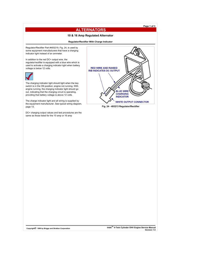
Regulator/Rectifier Part #493219, Fig. 24, is used by
some equipment manufacturers that have a charging
indicator light instead of an ammeter.
In addition to the red DC+ output wire, the
regulator/rectifier is equipped with a blue wire which is
used to activate a charging indicator light when battery
voltage is below 12 volts.
The charging indicator light should light when the key
switch is in the ON position; engine not running. With
engine running, the charging indicator light should go
out, indicating that the charging circuit is operating,
providing that battery voltage is above 12 volts.
The charge indicator light and all wiring is supplied by
the equipment manufacturer. See typical wiring diagram,
page 13.
DC+ charging output values and test procedures are the
same as those listed for the 10 amp or 16 amp
ALTERNATORS
10 & 16 Amp Regulated Alternator
Regulator/Rectifier With Charge Indicator
IntekTM V-Twin Cylinder OHV Engine Service Manual
Version 1.0Copyright© 1999 by Briggs and Stratton Corporation
Page 1 of 3
Fig. 24 - 493213 Regulator/Rectifier

Typical 16 Amp regulated alternator wiring
diagram - 6 pole switch with charge indicator light
Key Switch Test
*
Terminal 1
Grounded internally To Key Switch Case
ALTERNATORS
10 & 16 Amp Regulated Alternator
Regulator/Rectifier With Charge Indicator
IntekTM V-Twin Cylinder OHV Engine Service Manual
Version 1.0Copyright© 1999 by Briggs and Stratton Corporation
Page 2 of 3
Switch Position Continuity
1. OFF
2. RUN
3. START
*1 + 3 + 6
2 + 5 + 6
2 + 3 + 6
Terminal No. Function
1 To Ground (used only with insulated panel)
2
3
To Carburetor Solenoid
To Stop Switch Terminal On Engine
4 To Starter Solenoid (tab terminal)
5 To Battery (battery terminal on starter solenoid)
6 To Alternator (DC Output)

Testing Charge Indicator
It is important that the test procedure be done in a
systematic manner to identify whether the problem is
related to the regulator/rectifier or the charging indicator
wiring system. Follow test procedure in the sequence
listed.
A known good battery is required for this test.
Before testing the charging indicator system, test the
alternator and regulator/rectifier for proper output
Note: Output values are the same as the 10 amp and
16 amp system.
Symptom: Charge Indicator Light Will Not Light
Key Switch On - Engine Not Running
A jumper wire is required for this test.
Make sure key switch is in OFF position before
connecting jumper wire.
Note: Before disconnecting output harness
from connector, mark or identify the
charging indicator wire in the output harness.
If jumper wire contacts charging output wire during test,
while key switch is in ON position, wiring harness may
be damaged.
1. Disconnect output harness at white connector.
2. Attach one end of jumper wire to a good ground.
3. Attach other end of jumper wire to charge indicator
terminal in harness connector, Fig. 25.
a. Turn keyswitch to ON position.
b. If bulb lights, charge indicator wiring system is OK.
Replace regulator/rectifier.
c. If bulb does not light, replace bulb.
d. If new bulb does not light, the problem must be a
broken wire (open circuit) in charging indicator
circuit.
Symptom: Charge Indicator Light Stays
On - Engine Running
Note: Indicator light will remain on if battery voltage
is below 12 volts.
1. Check indicator light wiring.
a. If wiring is grounded, light will remain on when
engine is running.
b. If wiring is OK, replace regulator/rectifier.
ALTERNATORS
10 & 16 Amp Regulated Alternator
Regulator/Rectifier With Charge Indicator
IntekTM V-Twin Cylinder OHV Engine Service Manual
Version 1.0Copyright© 1999 by Briggs and Stratton Corporation
Page 3 of 3
Fig. 25 - Test Charge Indicator

The battery is of the 12 volt, lead acid, wet cell type.
This type is available as a maintenance free or a dry
charged battery.
The maintenance-free battery is filled with electrolyte at
the time of manufacture. The level of electrolyte cannot
be checked, Fig. 26.
The dry charged battery is manufactured with fully
charged plates. Electrolyte must be added at the time
that the battery is placed in service. Before activating a
dry charged battery, read and follow the manufacturers
recommended procedure.
Recommended battery sizes range from a minimum 30
ampere hour for warm temperature service to 50
ampere hour in coldest service.
WARNING: BATTERIES PRODUCE Hydrogen, an
explosive gas ! Do not store, charge
or use a battery near an open flame or
devices which utilize a pilot light or can
create a spark.
ALTERNATORS
Batteries
IntekTM
V-Twin Cylinder OHV Engine Service Manual
Version 1.0Copyright© 1999 by Briggs and Stratton Corporation
Page 1 of 1
Fig. 26 - Typical Wet Charge Battery

1. Before installing battery, connect all equipment to be
operated. Fig. 27.
2. Place battery in holder with a flat base. Tighten hold
downs evenly until snug. DO NOT overtighten.
3. Connect positive terminal to positive post FIRST to
prevent sparks from accidental grounding. Tighten
connectors securely.
4. Install protective cover over positive battery terminal
ends.
5. Connect negative terminal to negative battery terminal.
Tighten connectors securely.
ALTERNATORS
Batteries
Installation
IntekTM
V-Twin Cylinder OHV Engine Service Manual
Version 1.0Copyright© 1999 by Briggs and Stratton Corporation
Page 1 of 1
Fig. 27 - Typical 12 V Wiring Diagram

1. Physical check - clean if necessary.
a. Corrosion
b. Dirt
c. Terminal and clamps (secure - good conditions)
2. Bring battery to full charge.
Do not exceed the charge rate of 1/10 ampere for every
ampere of battery rating. Consult battery manufacturer
for charging recommendations. Overcharging may
cause battery failure.
a. Use a taper charger (automatically reduces charge
rate).
b. Fill battery cells with distilled water or tap water
(unless maintenance free type) after charging (for
batteries that have been in service).
Note: If battery gets hot to the touch or is spitting acid
(gassing) excessively, unplug charger
periodically.
3. With battery fully charged, check specific gravity
readings (unless maintenance free type) of each cell
with a Battery Hydrometer and record readings
(Fig. 28).
All readings should be above 1.250 (compensating for
temperature). If specific gravity readings varied .050 or
if ALL cells read less than 1.225, replace battery.
ALTERNATORS
Batteries
Checking Battery
IntekTM V-Twin Cylinder OHV Engine Service Manual
Version 1.0Copyright© 1999 by Briggs and Stratton Corporation
Page 1 of 1
Fig. 28 - Checking 12 V Battery Cells
(Lead Acid, Wet Cell, With Fill Caps)
Recommended