Tel.: +1 514-954-8219 ext. 8182
Ref.: AN 11/1.1.30-15/9 15 April 2015
Subject: Proposal for the amendment of Annex 6,
Parts I, II and III, the PANS-ATM and the PANS-OPS,
Volume I regarding harmonization and alignment of
terms, performance-based navigation (PBN), vision
systems, icing phraseology and airborne collision
avoidance system (ACAS)
Action required: Comments to reach Montreal by
15 July 2015
Sir/Madam,
1. I have the honour to inform you that the Air Navigation Commission, at the fourth
meeting of its 198th Session held on 24 February 2015, reviewed the work that the Flight Operations
Panel (FLTOPSP) undertook with regard to amendment proposals for Annex 6 — Operation of Aircraft,
Part I — International Commercial Air Transport — Aeroplanes, Part II — International General
Aviation — Aeroplanes and Part III — International Operations — Helicopters, the Procedures for Air
Navigation Services — Air Traffic Management (PANS-ATM, Doc 4444) and the Procedures for Air
Navigation Services — Aircraft Operations, Volume I — Flight Procedures (Doc 8168) regarding
harmonization and alignment of terms, performance-based navigation (PBN), vision systems, icing
phraseology and airborne collision avoidance system (ACAS). The Commission authorized the
transmission of these proposals to Contracting States and appropriate international organizations for
comments.
2. The aforementioned proposals to Annex 6, Parts I, II and III, the PANS-ATM and the
PANS-OPS, Volume I are explained in more detail in Attachment A. The proposed amendment to
Annex 6, Parts I, II and III, the PANS-ATM and the PANS-OPS, Volume I are contained in
Attachments B, C, D, E and F, respectively. A rationale box providing more information has been
included immediately following the proposals throughout the attachments.
999 Robert-Bourassa Boulevard
Montréal, Quebec
Canada H3C 5H7
Tel.: +1 514 954-8219-
Fax: +1 514 954-6077-
Email: [email protected]
www.icao.int
International
Civil Aviation
Organization
Organisation
de l’aviation civile
internationale
Organización
de Aviación Civil
Internacional
Международная
организация
гражданской
авиации
- 2 -
3. In examining the proposed amendments, you should not feel obliged to comment on
editorial aspects as such matters will be addressed by the Air Navigation Commission during its final
review of the draft amendments.
4. May I request that any comments you may wish to make on the proposed amendments to
Annex 6, Parts I, II and III, the PANS-ATM and the PANS-OPS, Volume I be dispatched to reach me not
later than 15 July 2015. The Air Navigation Commission has asked me to specifically indicate that
comments received after the due date may not be considered by the Commission and the Council. In this
connection, should you anticipate a delay in the receipt of your reply, please let me know in advance of
the due date.
5. In addition, the proposed amendments to Annex 6, Parts I, II and III, the PANS-ATM and
the PANS-OPS, Volume I are envisaged for applicability on 10 November 2016. Any comments you may
have thereon would be appreciated.
6. The subsequent work of the Air Navigation Commission and the Council would be
greatly facilitated by specific statements on the acceptability or otherwise of the amendment proposals.
7. Please note that, for the review of your comments by the Air Navigation Commission and
the Council, replies are normally classified as “agreement with or without comments”, “disagreement
with or without comments”, or “no indication of position”. If in your reply the expressions “no
objections” or “no comments” are used, they will be taken to mean “agreement without comment” and
“no indication of position”, respectively. In order to facilitate proper classification of your response, a
form has been included in Attachment G which may be completed and returned together with your
comments, if any, on the proposals in Attachments B to F.
Accept, Sir/Madam, the assurances of my highest consideration.
Raymond Benjamin
Secretary General
Enclosures:
A — Background
B — Proposed amendment to Annex 6, Part I
C — Proposed amendment to Annex 6, Part II
D — Proposed amendment to Annex 6, Part III
E — Proposed amendment to the PANS-ATM (Doc 4444)
F — Proposed amendment to PANS-OPS, Volume I
(Doc 8168)
G — Response form
ATTACHMENT A to State letter AN 11/1.1.30-15/9
BACKGROUND
1. HARMONIZATION, ALIGNMENT OF TERMS AND
LANGUAGE, AND CARGO COMPARTMENT FIRE
SUPPRESSION SYSTEMS
1.1 The proposed amendment contains the result of the review of all parts of Annex 6 to
introduce editorial amendments to Recommendations that have been superseded by Standards, as well as
to provisions with embedded applicability dates that have become outdated (ANC 189-3). The review, as
described in the work programme of the FLTOPSP, also identified the need to ensure consistency in
terminology (e.g. equipped and installed) across all parts of Annex 6 that have caused confusion in
interpretation and compliance. The first part of this task was concluded with the adoption of
Amendments 39 and 33 to Annex 6, Parts I and II, respectively.
1.2 The panel conducted a side-by-side comparison of Annex 6, Parts I and III provisions
prepared by the Helicopter Sub-group (HSG) in which editorial and contextual differences were
identified. Whilst reviewing the provisions, the panel grouped those needing minor wording or format
changes, and those with embedded dates that were no longer relevant. For Standards and Recommended
Practices (SARPs) requiring further work, proposals for addition to the work programme of the panel are
being submitted to the ANC.
1.3 Additionally, the amendment includes a proposed recommendation regarding cargo
compartment fire suppression time capabilities (CCFS) of aircraft. Extended diversion time operations
(EDTO) SARPs require that the operator consider the time capability of the CCFS for aircraft engaged in
EDTO. During the development of the EDTO provisions, the Special Operations Task Force (SOTF)
recognized that further work was necessary to determine whether similar requirements should also apply
to non-EDTO operations.
1.4 The panel reviewed the implication of the time limitation of these systems on existing
and future commercial operations of turbine engine aeroplanes. For that purpose, a survey of the existing
fleet capabilities in terms of cargo compartment fire suppression (CCFS) times was conducted. The
manufacturer’s survey response, although limited in terms of respondents, indicated that:
a) the majority of aircraft in current production are delivered with at least 60 minutes
CCFS coverage;
b) the majority of current production long-range aircraft have CCFS capability that
exceeds 195 minutes (the assumed EDTO threshold +15 minutes for three and four
engine aircraft);
c) early production models of older aircraft models (e.g. B747, DC10, A300B, etc.)
were produced with as little as 30 minutes CCFS capacity, but few if any are believed
to be in service;
d) there was no evidence of non-EDTO flights operating with less than 60 min CCFS
coverage; and

A-2
e) one operator was identified as flying long-range flights beyond CCFS coverage with
four engines aircraft across the southern Pacific ocean; it was noted, however, that
this was with the agreement of, and in compliance with, special conditions imposed
by the regulator.
1.5 After a review of in-service incidents and accidents related to cargo fire and the existing
fleet capabilities, the panel concluded that a recommendation for operators to remain within the coverage
of the CCFS was justified at no significant economic impact (most, if not all, of the current fleet has at
least 60 minutes CCFS).
2. UPDATE TO PBN PROVISIONS
2.1 The proposed amendment contains revised performance-based navigation (PBN)
provisions aligned with the current PBN framework necessary to solve issues related to one State’s
recognition of another State’s approvals by simplification of the PBN approval process. In addition, this
amendment proposal includes a framework in the form of a template, similar to the commercial air
transport operations specifications (OPSPECS) template, that would standardize specific approvals
(letters of authorization) for general aviation. The proposed specific approval template would not be
exclusively for PBN but would also support other provisions that require a specific approval thereby
facilitating harmonization.
2.2 It is envisaged that, for the most part, PBN would be managed by civil aviation
authorities in the same manner as other operations are managed in Annex 6. For commercial air transport
operations, this would be achieved by including standard operating procedures and training programmes
in the operator’s operations manual which is approved by the State of the Operator, whilst for general
aviation it would be by having the State of Registry establish corresponding criteria. The amendment
introduces the concept of “complex” PBN operations for “out of the ordinary” operations (e.g., similar to
Cat II and III instrument approach operations) which would be subject to a specific approval. For
commercial air transport operations, specific approvals are required to be included in the OPSPECS and
for GA specific approvals would need to be included in the proposed specific approval template.
2.3 The FLTOPSP in coordination with the PBN Study Group (PBNSG) are updating the
Performance-Based Navigation (PBN) Operational Approval Manual (Doc 9997) to provide guidance on
what should be considered a complex PBN operation. The amendment to the manual in this regard is
expected to be available by the end of 2015.
3. ADJUSTMENTS TO ENHANCED VISION SYSTEMS
3.1 The head-up displays/enhanced/synthetic (HUDs/EVS/SVS) and combined vision
systems (CVS) Standards adopted in Amendments 38, 33 and 19 to Annex 6, Parts I, II and III,
respectively, were not identical to the originally proposed FLTOPSP recommendations. As a result, the
enhanced vison guidance material included in the attachments to Annex 6 (i.e. Attachments I to Parts I
and III and Attachment 2.B to Part II) are no longer completely aligned with the adopted provisions.
Additionally, inconsistencies were inadvertently introduced to the general aviation provisions in Parts II
and III. The proposed amendment, as detailed in Appendix C, updates the guidance material in the
attachments and corrects the inconsistencies.

A-3
3.2 Furthermore, with the intent of keeping guidance material in Annex 6 attachments high
level and current for the long-term, some of the guidance material was transferred to the Manual of
All-Weather Operations (Doc 9365).
4. NEW STANDARD PHRASEOLOGY IN PANS-ATM
(DOC 4444) FOR DE/ANTI-ICING GROUND CREWS
AND FLIGHT CREWS
4.1 The proposed amendment introduces standard phraseology to be used by ground
de-icing/anti-icing crews when communicating with flight crews. In compliance with Standard 4.3.5.6 of
Annex 6, Part I and the corresponding provision 2.1.15 in Appendix 2 – Organization and Contents of an
Operations Manual which addresses the need to include instructions for the conduct and control of
ground de-icing/anti-icing operations in the Operations Manual, many operators have developed their
own phraseology to be used between the cockpit and ground de-icing/anti-icing crews.
4.2 The problem with multiple phraseologies has become more apparent as centralized
de-icing facilities (CDF) started operating in many States. In some instances, over eighty different
operators use a given centralized facility, each attempting to impose their own phraseology for these
operations. Some terms appear to be the same yet there are instances where there is no common
understanding.
5. IMPROVEMENTS TO ACAS PROVISIONS IN
PANS-OPS, VOLUME I (DOC 8168)
5.1 The proposed amendment contains changes to the operation of airborne collision
avoidance system (ACAS) equipment section, which will improve effectiveness of ACAS performance.
5.2 The operational monitoring of ACAS recognized two issues: insufficient or inappropriate
compliance with ACAS RAs by pilots; and the occurrence of unnecessary resolution advisories (RAs) for
routine air traffic management (ATM) operations due to high vertical rate encounters. As introduced at
the Twelfth Air Navigation Conference (AN-Conf/12) and in order to deal with those issues, this proposal
introduces two optional features which can bring significant operational and safety benefits for aircraft
operations. The performance and protection brought by ACAS are further enhanced by a new altitude
capture mode that drastically reduces the number of nuisance alerts and a new RA mode which is coupled
to the auto pilot/flight director to ensure accurate responses to the RAs. It is important to note that under
the new RA mode, aircraft would automatically respond to the RAs but at the same time, when necessary,
flight crew can select a manual response to the RAs.
— — — — — — — —

ATTACHMENT B to State letter AN 11/1.1.30-15/9
PROPOSED AMENDMENT TO ANNEX 6, PART I
NOTES ON THE PRESENTATION OF THE AMENDMENT
The text of the amendment is arranged to show deleted text with a line through it and new text highlighted
with grey shading, as shown below:
Text to be deleted is shown with a line through it. Text to be deleted
New text to be inserted is highlighted with grey shading. New text to be inserted
Text to be deleted is shown with a line through it
followed by the replacement text which is highlighted
with grey shading.
New text to replace existing text
B-2
TEXT OF PROPOSED AMENDMENT TO THE
INTERNATIONAL STANDARDS
AND RECOMMENDED PRACTICES
OPERATION OF AIRCRAFT
ANNEX 6
TO THE CONVENTION ON INTERNATIONAL CIVIL AVIATION
PART I
INTERNATIONAL COMMERCIAL AIR TRANSPORT — AEROPLANES
. . .
PROPOSAL REGARDING
HARMONIZATION, ALIGNMENT OF TERMS AND LANGUAGE, AND CARGO
COMPARTMENT FIRE SUPPRESSION SYSTEMS
CHAPTER 1. DEFINITIONS
. . .
Operator. A The person, organization or enterprise engaged in or offering to engage in an aircraft
operation.
Editorial note.— replace, instances of “An Operator” with “The
Operator” as applicable.
Origin
FLTOPSP/1
Rationale
“An Operator” and “The Operator” are terms used inconsistently across
Annex 6. Whilst it is not a significant issue, the FLTOPSP Sub-groups (SG)
addressing the ANC harmonization task were asked to analyse and make a
suggestion to use the terms consistently. Based on that review, the FLTOPSP
recommended that where the terms were used for similar purposes in a SARP,
the term “An Operator” be replaced with “The Operator” because the latter was
used more often and the term better aligns with the State of the Operator term.
Furthermore, as suggested by the Panel, the Editorial Unit (EDL) of ICAO was
consulted in reference to the best way to address the change of “an operator” to
“the operator” in all instances where it appears in all Parts of Annex 6. The
feedback received was that the indefinite article “a/an” was normally used
before general, non-specific nouns or to indicate membership in a group; that it
should be used in instances when referring to operators in general and not to a
specific operator. The article “the” was generally used before singular or plural
2.2.6
nouns that were specific or particular. In that regard, the definition of the “the
State of the Operator” when referencing operators was specific:

B-3
State of the Operator. The State in which the operator’s principal place of
business is located or, if there is no such place of business, the operator’s
permanent residence.
Based on the aforementioned, the proposal is to amend the definition of
“operator” to align it with the “the State of the Operator” and subsequently
search and replace all instances of “an operator” with “the operator” where the
above mentioned criteria is met.
. . .
Point of no return. The last possible geographic point at which an aeroplane aircraft can proceed to the
destination aerodrome as well as to an available en-route alternate aerodrome for a given flight.
Origin
ANC
Rationale
The PNR definition is being adjusted in all Parts of Annex 6 to accommodate
all “aircraft” instead of only “aeroplanes”.
. . .
CHAPTER 4. FLIGHT OPERATIONS
. . .
4.2.12 Passengers
. . .
4.2.12.3 In The operator shall ensure that in an emergency during flight, passengers shall be are
instructed in such emergency action as may be appropriate to the circumstances.
Origin
FLTOPSP/1
Rationale
This text is currently used in Annex 6, Part II (3.4.2.9.3) for the same purpose
and is considered to be more appropriate.
. . .
B-4
4.3 Flight preparation
. . .
4.3.5 Meteorological conditions
4.3.5.1 A flight to be conducted in accordance with the visual flight rules VFR shall not be
commenced unless current meteorological reports or a combination of current reports and forecasts
indicate that the meteorological conditions along the route or that part of the route to be flown under the
visual flight rules VFR will, at the appropriate time, be such as to enable compliance with these rules.
Origin
FLTOPSP/1
Rationale
VFR is a term included in “Abbreviations and Symbols”.
. . .
Editorial note.— Insert new paragraph 4.3.10 as follows:
4.3.10 Time capability of
cargo compartment fire suppression system
4.3.10.1 Recommendation.— All flights should be planned so that the diversion time to an
aerodrome where a safe landing could be made does not exceed the cargo compartment fire suppression
time capability of the aeroplane, when one is identified in the relevant aeroplane documentation, reduced
by an operational safety margin specified by the State of the Operator.
Note 1.— Cargo compartment fire suppression time capabilities will be identified in the relevant
aeroplane documentation when they are to be considered for the operation.
Note 2.— Fifteen minutes is an operational safety margin commonly retained for that purpose.
Note 3.— Refer to Chapter 4, 4.7 and Attachment D for considerations of time capability of cargo
compartment fire suppression systems for aeroplanes engaged in EDTO.
End of new text
Origin
FLTOPSP/1
Rationale
This recommendation originates from further work identified by the Special
Operations Task Force (SOTF) during the introduction of extended diversion
time operations (EDTO). In addressing the time capability considerations of
cargo fire suppression time capability (CCFS) for aircraft engaged in EDTO, it
was recognized that further work was necessary to confirm whether similar
requirements should also apply to non-EDTO operations.
After a review of in-service incidents and accidents related to cargo fire and
the existing fleet capabilities, the FLTOPSP concluded that operators
remaining within the coverage of the CCFSS was justified.
B-5
. . .
7.2 Navigation equipment
7.2.1 An aeroplane shall be provided with navigation equipment which will enable it to proceed:
a) in accordance with its operational flight plan; and b) in accordance with the requirements of air traffic services;
except when, if not so precluded by the appropriate authority, navigation for flights under the visual flight
rules VFR is accomplished by visual reference to landmarks.
Origin
FLTOPSP/1
Rationale
VFR is a term included in “Abbreviations and Symbols”.
. . .
ATTACHMENT D. GUIDANCE FOR OPERATIONS BY
TURBINE-ENGINED AEROPLANES BEYOND 60 MINUTES
TO AN EN-ROUTE ALTERNATE AERODROME INCLUDING
EXTENDED DIVERSION TIME OPERATIONS (EDTO)
(Supplementary to Chapter 4, 4.7)
. . .
3. Extended diversion time operations (EDTO) requirements
. . .
3.2 EDTO for aeroplanes with more than two turbine engines
. . .
3.2.5 EDTO significant systems
. . .
3.2.5.2 Consideration of time limitations
. . .
3.2.5.2.3 Not applicable. Considerations for the The maximum diversion time subject to cargo fire
suppression time limitations are considered part of the most limiting EDTO significant time limitations in
3.3.5.2.2.
. . .
3.2.9 Airworthiness certification requirements for extended
diversion time operations beyond the threshold time
3.2.9.1 Not applicable. There are no additional EDTO airworthiness certification requirements
for aeroplanes with more than two engines.
. . .

B-6
3.2.11 Airworthiness modifications and maintenance programme requirements
3.2.11.1 Not applicable. There are no additional EDTO airworthiness or maintenance
requirements for aeroplanes with more than two engines.
Origin
FLTOPSP/1
Rationale
Remove “not applicable” and leave the remainder as stand-alone text to
explain the applicability of the provision.
. . .
PROPOSAL REGARDING
UPDATED PBN PROVISIONS
CHAPTER 7. AEROPLANE COMMUNICATION AND
NAVIGATION EQUIPMENT
. . .
7.2.2 For operations where a navigation specification for performance-based navigation (PBN) has
been prescribed, an aeroplane shall, in addition to the requirements specified in 7.2.1:
a) be provided with navigation equipment which will enable it to operate in accordance with the
prescribed navigation specification(s); and
b) be authorized by the State of the Operator for such operations. have information relevant to the
aeroplane navigation specification capabilities listed in the flight manual or other aeroplane
documentation approved by the State of the Design or State of Registry; and
c) have information relevant to the aeroplane navigation specification capabilities included in the
MEL.
Note.— Guidance on aeroplane documentation is contained in the Performance-based Navigation
(PBN) Manual (Doc 9613).
7.2.3 The State of the Operator shall, for operations where a navigation specification for PBN has
been prescribed, ensure that the operator has established and documented:
a) normal and abnormal procedures including contingency procedures;
b) flight crew qualification and proficiency requirements in accordance with the appropriate
navigation specifications;
c) a training programme for relevant personnel consistent with the intended operations; and
d) appropriate maintenance procedures to ensure continued airworthiness in accordance with the
appropriate navigation specifications.

B-7
Note 1.— Guidance on safety risks and mitigations for PBN operations, in accordance with Annex 19,
are contained in the Performance-based Navigation (PBN) Operational Approval Manual (Doc 9997).
Note 2.— Electronic navigation data management is an integral part of normal and abnormal
procedures.
7.2.4 The State of the Operator shall issue a specific approval for complex navigation
specifications.
Note.— Guidance on specific approvals for complex navigation specifications (e.g. RNP AR) is
contained in the Performance-based Navigation (PBN) Operational Approval Manual (Doc 9997).
Editorial note.— Renumber subsequent paragraphs accordingly.
. . .
B-8
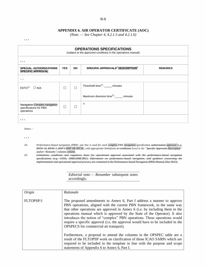
APPENDIX 6. AIR OPERATOR CERTIFICATE (AOC)
(Note. — See Chapter 4, 4.2.1.5 and 4.2.1.6)
. . .
OPERATIONS SPECIFICATIONS (subject to the approved conditions in the operations manual)
. . .
SPECIAL AUTHORIZATIONS SPECIFIC APPROVAL
YES NO SPECIFIC APPROVALS9 DESCRIPTION
9 REMARKS
. . .
EDTO14
☐ N/A ☐ ☐ Threshold time
15: _____ minutes
Maximum diversion time15
: _____ minutes
Navigation Complex navigation specifications for PBN operations
☐ ☐
16
. . .
Notes.—
. . . 16. Performance-based navigation (PBN): one line is used for each complex PBN navigation specification authorization approval (e.g.
RNAV 10, RNAV 1, RNP 4 RNP AR APCH), with appropriate limitations or conditions listed in the “Specific Approvals Description”
and/or “Remarks” columns column.
17. Limitations, conditions and regulatory basis for operational approval associated with the performance-based navigation
specifications (e.g. GNSS, DME/DME/IRU). Information on performance-based navigation, and guidance concerning the
implementation and operational approval process, are contained in the Performance-based Navigation (PBN) Manual (Doc 9613).
Editorial note.— Renumber subsequent notes accordingly.
Origin
FLTOPSP/1
Rationale
The proposed amendments to Annex 6, Part I address a manner to approve
PBN operations, aligned with the current PBN framework, in the same way
that other operations are approved in Annex 6 (i.e. by including them in the
operations manual which is approved by the State of the Operator). It also
introduces the notion of “complex” PBN operations. These operations would
require a specific approval (i.e. the approval would have to be included in the
OPSPECS for commercial air transport).
Furthermore, a proposal to amend the columns in the OPSPEC table are a
result of the FLTOPSP work on clarification of those ICAO SARPs which are
required to be included in the template in line with the purpose and scope
statements of Appendix 6 to Annex 6, Part I.

B-9
Finally, the Performance-Based Navigation (PBN) Operational Approval
Manual (Doc 9997) is being updated to provide guidance on what should be
considered a complex PBN operation.
. . .
PROPOSAL REGARDING
ADJUSTMENTS TO ENHANCED VISION SYSTEMS
ATTACHMENT I. AUTOMATIC LANDING SYSTEMS, HEAD-UP DISPLAY (HUD),
EQUIVALENT DISPLAYS AND VISION SYSTEMS
Supplementary to Chapter 4, 4.2.8.1.1, and Chapter 6, 6.23
Introduction
The material in this attachment provides guidance for certified automatic landing systems, HUD,
equivalent displays and vision systems intended for operational use in aircraft aeroplanes engaged in
international air navigation. A HUD, vision These systems and hybrid systems may be installed and
operated to reduce workload, improve guidance, enhance reduce flight technical error and enhance
situational awareness and/or obtain an operational credit by establishing minima below the aerodrome
operating minima, for approach ban purposes, or reducing the visibility requirements or requiring fewer
ground facilities as compensated for by airborne capabilities credits. Automatic landing systems, HUD,
equivalent displays and vision systems may be installed separately or together as part of a hybrid system.
Any operational credit to be obtained from for their use requires a specific approval from the State of the
Operator.
Note 1.— “Vision systems” is a generic term referring to the existing systems designed to provide
images, i.e. enhanced vision systems (EVS), synthetic vision systems (SVS) and combined vision systems
(CVS).
Note 2.— Operational credit can be granted only within the limits of the design airworthiness
approval.
Note 3.— Currently, operational credit has been given only to vision systems containing an image
sensor providing a real-time image of the actual external scene on the a HUD.
Note 4.— More detailed information and guidance on automatic landing systems, HUD, equivalent
displays and vision systems is contained in the Manual of All-Weather Operations (Doc 9365). This
manual should be consulted in conjunction with this attachment.

B-10
1. HUD and equivalent displays
1.1 General
1.1.1 A HUD presents flight information into the pilot’s forward external field of view without
significantly restricting that external view.
1.1.2 A variety of flight Flight information may should be presented on a HUD depending on or an
equivalent display, as required for the intended flight operation, flight conditions, systems capabilities and
operational approval. A HUD may include, but is not limited to, the following: use.
a) airspeed; b) altitude; c) heading; d) vertical speed; e) angle of attack; f) flight path or velocity vector; g) attitude with bank and pitch references; h) course and glide path with deviation indications; i) status indications (e.g. navigation sensor, autopilot, flight director); and j) alerts and warning displays (e.g. ACAS, wind shear, ground proximity warning).
1.2 Operational applications
1.2.1 Flight operations with a HUD can improve situational awareness by combining flight
information located on head-down displays with the external view to provide pilots with more immediate
awareness of relevant flight parameters and situation information while they continuously view the
external scene. This improved situational awareness can also reduce errors in flight operations and
improve the pilot’s ability to transition between instrument and visual references as meteorological
conditions change. Flight operations applications may include the following: a) enhanced situational awareness during all flight operations, but especially during taxi, take-off,
approach and landing; b) reduced flight technical error during take-off, approach and landing; and c) improvements in performance due to precise prediction of touchdown area, tail strike
awareness/warning and rapid recognition of and recovery from unusual attitudes. 1.2.2 A HUD may be used for the following purposes: a) to supplement conventional flight deck instrumentation in the performance of a particular task or
operation. The primary cockpit instruments remain the primary means for manually controlling or manoeuvring the aircraft; and
B-11
b) or as a primary flight display: 1) information presented by the HUD may be used by the pilot in lieu of scanning head-down
displays. Operational approval of a HUD for such use allows the pilot to control the aircraft by reference to the HUD for approved ground or flight operations; and
2) information presented by the HUD may be used as a means to achieve additional navigation
or control performance. The required information is displayed on the HUD. Operational credit, in the form of lower minima, for a HUD used if certified for this purpose may be approved for a particular aircraft or automatic flight control system. Additional credit may also be allowed when conducting HUD operations in situations where automated systems are otherwise used.
1.2.3 A An approved HUD, as a stand-alone system, may:
a) qualify for operations with reduced visibility or reduced RVR; or
b) replace some parts of the ground facilities such as touchdown zone and/or centre line lights.
Examples and references to publications in this regard can be found in the Manual of All-Weather
Operations (Doc 9365). 1.2.4 A HUD or The functions of a HUD may be provided by a suitable equivalent display is one
that has at least the following characteristics: it has a head-up presentation not requiring transition of
visual attention from head down to head up; it displays sensor-derived imagery conformal to the pilot’s
external view; it permits simultaneous view of the EVS sensor imagery, required aircraft flight
symbology, and the external view; and its display characteristics and dynamics are suitable for manual
control of the aircraft, however, . However, before such systems can be used, the appropriate
airworthiness and operational approvals approval should be obtained.
1.3 HUD training
1.3.1 Training and recent experience requirements for operations using HUD or equivalent displays
should be established, monitored and approved by the State of the Operator. Training requirements
programmes should include requirements for recent experience if the be approved by the State determines
that these requirements are significantly different than the current requirements for the use of
conventional head-down instrumentation of the Operator and the implementation of the training should be
subject to oversight by that State.
1.3.2 HUD The training should address all flight operations for which the HUD is designed and
operationally approved. Some training elements may require adjustments based on whether the aeroplane
has a single or dual HUD installation. Training should include contingency procedures required in the
event of head-up display degradation or failure. HUD training should include the following elements as
applicable to the intended use: or equivalent display is used. a) an understanding of the HUD, its flight path, energy management concepts and symbology. This
should include operations during critical flight events (e.g. ACAS traffic advisory/resolution advisory, upset and wind shear recovery, engine or system failure);
b) HUD limitations and normal procedures, including maintenance and operational checks
performed to ensure normal system function prior to use. These checks include pilot seat adjustment to attain and maintain appropriate viewing angles and verification of HUD operating modes;
c) HUD use during low visibility operations, including taxi, take-off, instrument approach and

B-12
landing in both day and night conditions. This training should include the transition from head-down to head-up and head-up to head-down operations;
d) failure modes of the HUD and the impact of the failure modes or limitations on crew
performance; e) crew coordination, monitoring and verbal call-out procedures for single HUD installations with
head-down monitoring for the pilot not equipped with a HUD and head-up monitoring for the pilot equipped with a HUD;
f) crew coordination, monitoring and verbal call-out procedures for dual HUD installations with use
of a HUD by the pilot flying the aircraft and either head-up or head-down monitoring by the other pilot;
g) consideration of the potential for loss of situational awareness due to “tunnel vision” (also known
as cognitive tunnelling or attention tunnelling); h) any effects that weather, such as low ceilings and visibilities, may have on the performance of a
HUD; and i) HUD airworthiness requirements.
2. Vision systems
2.1 General
2.1.1 Vision systems can display electronic real-time images of the actual external scene achieved
through the use of image sensors (,i.e. EVS) , or display synthetic images, which are derived from the on-
board avionic systems (, i.e. SVS) . Vision systems can also consist of a combination of these two
systems or , called combined vision systems (i.e. CVS) . Such a system may display electronic real-time
images of the external scene using the EVS component of the system. However, the merging of EVS and
SVS into a CVS is dependent on the intended function (e.g. whether or not there is intent to achieve
operational credit). The information from vision systems may be displayed head-up and/or head-down.
Operational credit, which may be granted to vision systems, is currently only applicable when real-time
image information is displayed head-up. 2.1.2 The information from vision systems may be displayed on a head-up or head-down display.
When enhanced vision imagery is displayed on a HUD, it should be presented to the pilot’s forward
external field of view without significantly restricting that external view. 2.1.3 The enhanced position fixing and guidance provided by SVS may provide additional safety
for all phases of flight especially low visibility taxi, take-off, approach and landing operations. 2.1.4 Light emitting diode (LED) lights may not be visible to infrared-based vision systems due to
the fact that LED lights are not incandescent and they do not have a significant heat signature. Operators
of such vision systems will need to acquire information about the LED implementation programmes at
aerodromes where they intend to operate. More details about the consequences of LED lights are
contained in the Manual of All-Weather Operations (Doc 9365).
B-13
2.2 Operational applications
2.2.1 Flight operations with enhanced vision image sensors EVS allow the pilot to view an image of
the external scene obscured by darkness or other visibility restrictions. When the external scene is
partially obscured, enhanced vision imaging may The use of EVS will also allow the pilot to acquire
acquisition of an image of the external scene earlier than with natural or , unaided vision, hence providing
for a smoother transition to references by natural vision. The improved acquisition of an image of the
external scene may improve situational awareness. It may also qualify for operational credit if the
information from the vision system is presented to the pilots in a suitable way and the necessary
airworthiness approval and specific approval by the State of the Operator have been obtained for the
combined system.
2.2.2 Vision system imagery may also allow enable pilots to detect other aircraft on the ground,
terrain or obstructions on the runway or adjacent to runways or taxiways. A vision system image can also
provide visual cues to enable earlier runway alignment and a more stabilized approach.
2.2.3 The combined display of aircraft performance, guidance and imagery may allow the pilot to
maintain a more stabilized approach and smoothly transition from enhanced visual references to natural
visual references.
2.3 Vision systems training Operational concepts
2.3.1 Training requirements should be established, monitored and approved by the State of the
Operator. Training requirements should include recency of experience requirements if the State of the
Operator determines that these requirements are significantly different than the current requirements for
the use of a HUD without enhanced vision imagery or conventional head-down instrumentation.
2.3.2 Training should address all flight operations for which the vision system is approved. This
training should include contingency procedures required in the event of system degradation or failure.
Training for situational awareness should not interfere with other required operations. Training for
operational credit should also require training on the applicable HUD used to present the enhanced visual
imagery. Training should include the following elements as applicable:
a) an understanding of the system characteristics and operational constraints; b) normal procedures, controls, modes and system adjustments (e.g. sensor theory including radiant
versus thermal energy and resulting images); c) operational constraints, normal procedures, controls, modes and system adjustments; d) limitations; e) airworthiness requirements; f) vision system display during low visibility operations, including taxi, take-off, instrument
approach and landing; system use for instrument approach procedures in both day and night conditions;
g) failure modes and the impact of failure modes or limitations upon crew performance, in
particular, for two-pilot operations; h) crew coordination and monitoring procedures and pilot call-out responsibilities;

B-14
i) transition from enhanced imagery to visual conditions during runway visual acquisition; j) rejected landing: with the loss of visual cues of the landing area, touchdown zone or rollout area; k) any effects that weather, such as low ceilings and visibilities, may have on the performance of the
vision system; and l) effects of aerodrome lighting using LED lights.
2.4 Operational concepts
2.4.1 Instrument approach operations that involve the use of vision systems include the an
instrument phase and the a visual phase. The instrument phase ends at the published MDA/H or DA/H
unless a missed approach is initiated. Using the EVS or CVS does not change the applicable MDA/H or
DA/H. The continued approach to landing from MDA/H or DA/H will be conducted using visual
references. The This also applies to operations with vision systems. The difference is that the visual
references will be acquired by use of an EVS or CVS, natural vision or a the vision system in
combination of the two with natural vision (see Figure I-1).
2.4.2 2.3.2 Down to a defined height in the visual segment, typically at or below 30 m (100 ft), the
visual references will may be acquired solely by means of the vision system. The defined height depends
on the airworthiness approval and specific approval by the State of the Operator. Below this height the
visual references should be solely based on natural vision. In the most advanced applications, the vision
system is expected to be able to may be used down to touchdown without the requirement for natural
vision acquisition of visual references. Using the EVS or CVS does not change the classification of an
instrument approach procedure, since the published DA/H remains unchanged and manoeuvring below
DA/H is conducted by visual references acquired by means of the EVS or CVS. This means that such a
vision system may be the sole means of acquiring visual references and can be used without natural
vision.
2.4.3 In addition to the operational credit that EVS/CVS is able to provide, these systems may also
provide an operational and safety advantage through improved situational awareness, earlier acquisition
of visual references and smoother transition to references by natural vision. These advantages are more
pronounced for Type A approach operations than for Type B approach operations.
2.4 Vision systems training
2.4.1 Training and recent experience requirements should be established by the State of the
Operator. Training programmes should be approved by the State of the Operator and the implementation
of the training should be subject to oversight by that State. Training should address all flight operations
for which the vision system is used.
2.5 Visual references
2.5.1 The In principle, the required visual references do not change due to the use of an EVS or
CVS, but those references are allowed to be acquired by means of either vision system until a certain
height during the approach (see Figure I-1) as described in paragraph 2.3.1.

B-15
Editorial note.— Move Figure I-1 under new paragraph 2.3.1.
EVS operations
Figure I-1. EVS operations — transition from instrument to visual references
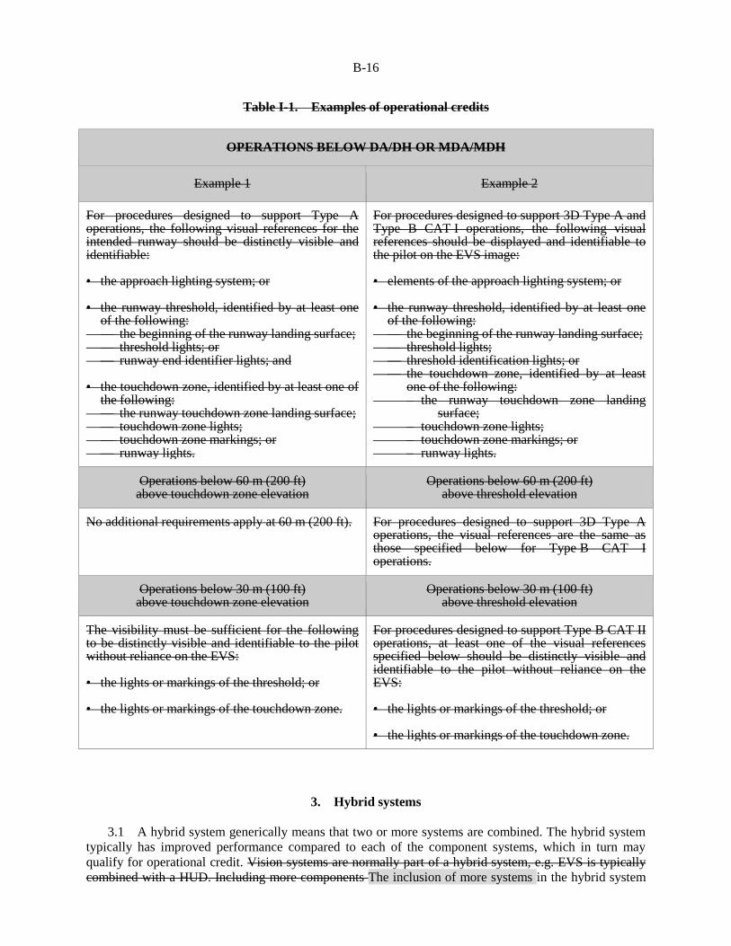
2.5.2 In regions States that have developed requirements for operations with vision systems, the use of
visual references have been regulated and examples of this are indicated in Table I-1 provided in the
Manual of All-Weather Operations (Doc 9365).
Visual segment= visual manoeuvring
Instrument segment
MDA/H, DA/H
H above THR
(H = 30 m (100 ft) or 60 m (200 ft))
References bynatural vision
References byHUD and EVS
B-16
Table I-1. Examples of operational credits
OPERATIONS BELOW DA/DH OR MDA/MDH
Example 1 Example 2
For procedures designed to support Type A operations, the following visual references for the intended runway should be distinctly visible and identifiable: • the approach lighting system; or • the runway threshold, identified by at least one
of the following: — the beginning of the runway landing surface; — threshold lights; or — runway end identifier lights; and • the touchdown zone, identified by at least one of
the following: — the runway touchdown zone landing surface; — touchdown zone lights; — touchdown zone markings; or — runway lights.
For procedures designed to support 3D Type A and Type B CAT I operations, the following visual references should be displayed and identifiable to the pilot on the EVS image: • elements of the approach lighting system; or • the runway threshold, identified by at least one
of the following: — the beginning of the runway landing surface; — threshold lights; — threshold identification lights; or — the touchdown zone, identified by at least
one of the following: – the runway touchdown zone landing
surface; – touchdown zone lights; – touchdown zone markings; or – runway lights.
Operations below 60 m (200 ft) above touchdown zone elevation
Operations below 60 m (200 ft) above threshold elevation
No additional requirements apply at 60 m (200 ft). For procedures designed to support 3D Type A operations, the visual references are the same as those specified below for Type B CAT I operations.
Operations below 30 m (100 ft) above touchdown zone elevation
Operations below 30 m (100 ft) above threshold elevation
The visibility must be sufficient for the following to be distinctly visible and identifiable to the pilot without reliance on the EVS: • the lights or markings of the threshold; or • the lights or markings of the touchdown zone.
For procedures designed to support Type B CAT II operations, at least one of the visual references specified below should be distinctly visible and identifiable to the pilot without reliance on the EVS: • the lights or markings of the threshold; or • the lights or markings of the touchdown zone.
3. Hybrid systems
3.1 A hybrid system generically means that two or more systems are combined. The hybrid system
typically has improved performance compared to each of the component systems, which in turn may
qualify for operational credit. Vision systems are normally part of a hybrid system, e.g. EVS is typically
combined with a HUD. Including more components The inclusion of more systems in the hybrid system

B-17
normally enhances the performance of the system. The Manual of All-Weather Operations (Doc 9365)
contains some examples of hybrid systems.
3.2 Table I-2 provides some examples of hybrid system components. Any combination of the listed
systems may constitute a hybrid system. The degree of operational credit that may be given to a hybrid
system depends on its performance (accuracy, integrity and availability) as assessed and determined by
the certification and operational approval processes.
Table I-2. Examples of hybrid system components
Systems based on image sensors Systems not based on image sensors
EVS • Passive infrared sensors • Active infrared sensors • Passive millimetre wave radiometer • Active millimetre wave radar
SVS
Autoflight systems, flight control computers, automatic landing systems
Systems for position fixing
CVS (where the EVS component as above qualifies for operational credit)
CVS (the SVS component)
HUD, equivalent display
ILS, GNSS
4. Operational credits
4.1 Aerodrome operating minima are expressed in terms of minimum visibility/RVR and MDA/H
or DA/H. With respect to operational credit this means that the visibility/RVR requirements, established
in the instrument approach procedure, may be reduced or satisfied for aircraft equipped with appropriately
approved vision systems such as EVS. Reasons for granting operational credit may be when aircraft are
better equipped than what was originally considered when designing the instrument approach procedure
or when runway visual aids considered in the design of the procedure are not available but can be
compensated for by on-board equipment. When aerodrome operating minima are established, the
combined capability of the aeroplanes equipment and on-ground infrastructure should be taken into
account. Better equipped aeroplanes may be able to operate into lower natural visibility conditions, lower
DA/H and/or operate with less ground infrastructure. Operational credit means that the aerodrome
operating minima may be reduced in case of suitably equipped aeroplanes. Another way to grant
operational credit is to allow visibility requirements to be fulfilled, wholly or partly, by means of the
on-board systems. HUD, automatic landing or vision systems were not available at the time when the
criteria for aerodrome operating minima were originally established.
4.2 Credits related to visibility/RVR can be given using at least three concepts. The first concept is
to reduce the required RVR which will allow the aircraft to continue the approach beyond the approach
ban point with a reported RVR lower than what was established for the approach procedure. Where a
minimum visibility is prescribed, a second concept to grant operational credit may be used. In this case,
the required minimum visibility is kept unchanged, but it is satisfied by means of the on-board equipment,
typically an EVS. The result of both these concepts is that operations are allowed in meteorological
conditions where otherwise they would not be possible. A third concept is to give operational credit by
allowing operations in visibility/RVR which are not lower than those established for the approach

B-18
procedure, but the approach operation is conducted with less facilities on the ground. One example of the
latter is to allow Category II operations without touchdown and/or centre line lights, compensated for by
additional on-board equipment, e.g. a HUD.
4.3 Granting The granting of operational credits does not affect the classification (i.e. Type or
Category) of an instrument approach procedure since, as described in Standard 4.2.8.3, instrument
approach procedures they are designed to support a given instrument approach operation (i.e. type,
category). However, the design of those procedures may not take into consideration on-board equipment
that may compensate for facilities on the ground. Instrument approach operations instrument approach
operations conducted using aeroplanes with the minimum equipment prescribed.
4.4 In order to provide optimum service, the ATS may have to be informed about the capabilities of
better-equipped aircraft, e.g. which is the minimum RVR required.
4.5 In addition to the operational credit that a HUD, vision systems and hybrid systems are able to
provide, these systems will also provide an operational and safety advantage through improved situational
awareness, earlier acquisition of visual references and smoother transition to references by natural vision.
These advantages are more pronounced for 3D Type A approach operations than for Type B approach
operations.
4.3 The relation between the procedure design and the operation can be described as follows. The
OCA/H is the end product of the procedure design, which does not contain any RVR or visibility values.
Based on the OCA/H and all the other elements such as available runway visual aids, the operator will
establish MDA/H or DA/H and RVR/visibility, i.e. the aerodrome operating minima. The values derived
should not be less than those prescribed by the State of the Aerodrome.
5. Operational procedures
5.1 It is not prohibited to use vision systems in connection with circling. However, due to the
system layout of a vision system and the nature of a circling procedure, key visual references can be
obtained only by natural vision, and operational credit is not feasible for existing vision systems. The
vision system may provide additional situational awareness.
5.2 The operational procedures associated with the use of a HUD, vision systems and hybrid
systems should be included in the operations manual. The instructions in the operations manual should
include:
a) any limitation that is imposed by the airworthiness or operational approvals; b) how operational credit affects: 1) flight planning with respect to destination and alternate aerodromes; 2) ground operations; 3) flight execution, e.g. approach ban and minimum visibility; 4) crew resource management that takes into account the equipment configuration, e.g. the pilots
may have different presentation equipment; 5) standard operating procedures, e.g. use of autoflight systems, call-outs that may be particular

B-19
to the vision system or hybrid system, criteria for stabilized approach; 6) ATS flight plans and radio communication. 5.1 In accordance with 6.23.2 the operator should develop suitable operational procedures associated with the use of an automatic landing system, a HUD or an equivalent display, vision systems and hybrid systems. These procedures should be included in the operations manual and cover at least the following: a) limitations; b) operational credits; c) flight planning; d) ground and airborne operations; e) crew resource management; f) standard operating procedures; and g) ATS flight plans and communication.
6. Approvals
6.1 General
Note.— When the application for a specific approval relates to operational credits for systems not
including a vision system, the guidance on approvals in this attachment may be used to the extent
applicable as determined by the State of the Operator.
6.1.1 An operator that wishes to conduct operations with an automatic landing system, a HUD or an
equivalent display, a vision system or a hybrid system will need to obtain certain approvals (i.e. 4.2.8.1.1
and 6.23) as prescribed in the relevant SARPs. The extent of the approvals will depend on the intended
operation and the complexity of the equipment. 6.1.2 Enhanced vision imagery may be used to improve Systems that are not used for an operational
credit or otherwise critical to the aerodrome operating minima, e.g. vision systems used to enhance
situational awareness may be used without a specific operational approval. However, the standard
operating procedures for these types of operations need to be systems should be specified in the
operations manual. An example of this type of operation may include an EVS or an SVS on a head-down
display that is used only for situational awareness of the surrounding area of the aircraft aeroplane during
ground operations where the display is not in the pilot’s primary field of view. For enhanced situational
awareness, the installation and operational procedures need to ensure that the operation of the vision
system does not interfere with normal procedures or the operation or use of other aircraft aeroplane
systems. In some cases, modifications to these normal procedures for other aircraft aeroplane systems or
equipment may be necessary to ensure compatibility. 6.1.3 When a vision system or a hybrid system with vision systems imagery is used for operational
credit, operational approvals will typically require that the imagery be combined with flight guidance and
presented on a HUD. Operational approvals may require that this information also be presented on a

B-20
head-down display. Operational credit may be applied for any flight operation, but credit for instrument
approach and take-off operations is most common. 6.1.4 When the application for approval relates to operational credits for systems not including a
vision system, the guidance in this attachment may be used to the extent applicable as determined by the
State of the Operator or the State of Registry for general aviation. 6.1.5 Operators should be aware that some States may require some information about the
operational credit(s) which has been granted by the State of the Operator or the State of Registry for
general aviation. Typically the approval from that State will have to be presented, and in some cases the
State of the Aerodrome may wish to issue an approval or to validate the original approval.
6.1.3 The Standard in Annex 6, Part I, 6.23.1, requires that the use of an automatic landing system,
a HUD, an equivalent display, EVS, SVS or CVS or any combination of those systems into a hybrid
system, should be approved by the State of the Operator when those systems are used “for the safe
operation of an aeroplane”. When operational credits have been granted by the State of the Operator per
Standard in Annex 6, Part I, 4.2.8.1.1, the use of that system becomes essential for the safety of such
operations and is subject to a specific approval. The use of these systems solely for enhanced situational
awareness, reduced flight technical error and/or reduced workload is an important safety feature, but does
not require a specific approval.
6.1.4 Any operational credit that has been granted should be reflected in the operation
specifications for the type or individual aeroplane as applicable.
6.2 Approvals Specific approvals for operational credit
6.2.1 To obtain a specific approval for operational credit the operator will need to specify the
desired operational credit and submit a suitable application. The content of a suitable application should
include: a) Applicant details. required for all approval requests. The official name and business or trading
name(s), address, mailing address, e-mail address and contact telephone/fax numbers of the applicant.
Note.— For AOC holders, the holder’s company name, AOC number and e-mail. address should
be required. b) Aircraft details. required for all approval requests. Aircraft make(s), model(s) and registration
mark(s). c) Operator’s vision system compliance list. The contents of the compliance list are included in
Table I-3. the Manual of All-Weather Operations (Doc 9365). The compliance list should include the information that is relevant to the specific approval requested and the registration marks of the aircraft involved. If more than one type of aircraft/fleet is included in a single application a completed compliance list should be included for each aircraft/fleet.
d) Documents to be included with the application. Copies of all documents referred to in column 4
of which the operator’s vision system compliance list (Table I-3) operator has made references should be included when returning in the completed application form to the civil aviation authority. There should be no need to send complete manuals; only the relevant sections/pages should be required. Additional guidance material can be found in the Manual of All-Weather Operations (Doc 9365).
e) Name, title and signature.

B-21
Table I-3. Example of an AOC vision system 6.2.2 The following items should be covered in a vision
systems compliance list:
Main heading Expanded areas to be
addressed by the application Sub-requirements
Operator’s operations
manual reference or document reference
1.0 Reference documents
used in compiling the
submission
The submission should be
based on current up-to-date
regulatory material.
A compliance statement
showing how the criteria of the
applicable regulations and
requirements have been
satisfied.
2.0 Aircraft flight manual
(AFM)
A copy of the relevant AFM
entry showing the aircraft
certification basis for the
vision system and any
operational conditions.
3.0 Feedback and reporting
of significant problems
An outline of the process for
the reporting of failures in the
operational use of procedures.
Note.— In particular,
significant problems with the
vision system/HUD system,
reporting on circumstances/
locations where the vision
system was unsatisfactory.
4.0 Instrument approach
chart provider and
operating minima
The name of the provider of
the relevant instrument
approach charts.
Confirmation that all
aerodrome operating minima
are established in accordance
with the method acceptable to
the relevant authority.
5.0 Operations manual
entries and standard
operating procedures
Manufacturer/operator-
developed.
Manufacturer’s procedures are
recommended as a starting
point and should include at
least the items in the sub-
Definitions.
Check that crew members are
qualified for vision
system/HUD operations.
MEL handling.
Equipment required for vision
system operations.

B-22
Main heading Expanded areas to be
addressed by the application Sub-requirements
Operator’s operations
manual reference or document reference
requirements column. Types of approach where vision
systems can be used.
Statement that the
autopilot/flight director should
be used whenever possible.
Minimum visual references for
landing.
Approach ban and RVR.
Stabilized approach criteria.
Correct seating and eye
position.
Crew coordination, e.g. duties
of the pilot flying and the pilot
not flying: • limitations; • designation of handling and
non-handling pilots; • use of automatic flight
control system; • checklist handling; • approach briefing; • radio communications
handling; • monitoring and cross-
checking of instruments and radio aids; and
• use of the repeater display by the pilot not flying.
Contingency procedures
including: • failures above and below
decision height; • ILS deviation warnings; • autopilot disconnect; • auto-throttle disconnect; • electrical failures; • engine failure; • failures and loss of visual
references at or below decision height;
• vision system/HUD failure below normal decision height;
• wind shear; • ACAS warnings; • EGPWS warnings.

B-23
Main heading Expanded areas to be
addressed by the application Sub-requirements
Operator’s operations
manual reference or document reference
6.0 Safety risk assessment
Operator’s safety risk
assessment.
1. reference documents used in compiling the submission for approval;
2. flight manual;
3. feedback and reporting of significant problems;
4. requested operational credit and resulting aerodrome operating minima;
5. operations manual entries including MEL and standard operating procedures;
6. safety risk assessments;
7. training programmes; and
8. continuing airworthiness
Expanded guidance on these items is contained in the Manual of All-Weather Operations (Doc 9365).
Origin
FLTOPSP/1
Rationale
Amendment 38 to Annex 6, Part I introduced significant modifications to the
FLTOPSP proposal regarding visions systems during the adoption process. As
a result, the accompanying guidance material was no longer clear and in some
cases no longer relevant. This proposal updates the guidance material
accordingly. Furthermore, in an effort to keep guidance material in the
attachments to Annex 6 more stable, a significant portion of that material has
been transferred to the Manual of All Weather Operations (Doc 9365).
. . .
— — — — — — — —

ATTACHMENT C to State letter AN 11/1.1.30-15/9
PROPOSED AMENDMENT TO ANNEX 6, PART II
NOTES ON THE PRESENTATION OF THE AMENDMENT
The text of the amendment is arranged to show deleted text with a line through it and new text highlighted
with grey shading, as shown below:
Text to be deleted is shown with a line through it. Text to be deleted
New text to be inserted is highlighted with grey shading. New text to be inserted
Text to be deleted is shown with a line through it
followed by the replacement text which is highlighted
with grey shading.
New text to replace existing text
C-2
TEXT OF PROPOSED AMENDMENT TO THE
INTERNATIONAL STANDARDS
AND RECOMMENDED PRACTICES
OPERATION OF AIRCRAFT
ANNEX 6
TO THE CONVENTION ON INTERNATIONAL CIVIL AVIATION
PART II
INTERNATIONAL GENERAL AVIATION — AEROPLANES
. . .
PROPOSAL REGARDING
HARMONIZATION, ALIGNMENT OF TERMS AND LANGUAGE, AND CARGO
COMPARTMENT FIRE SUPPRESSION SYSTEMS
CHAPTER 1. DEFINITIONS
. . .
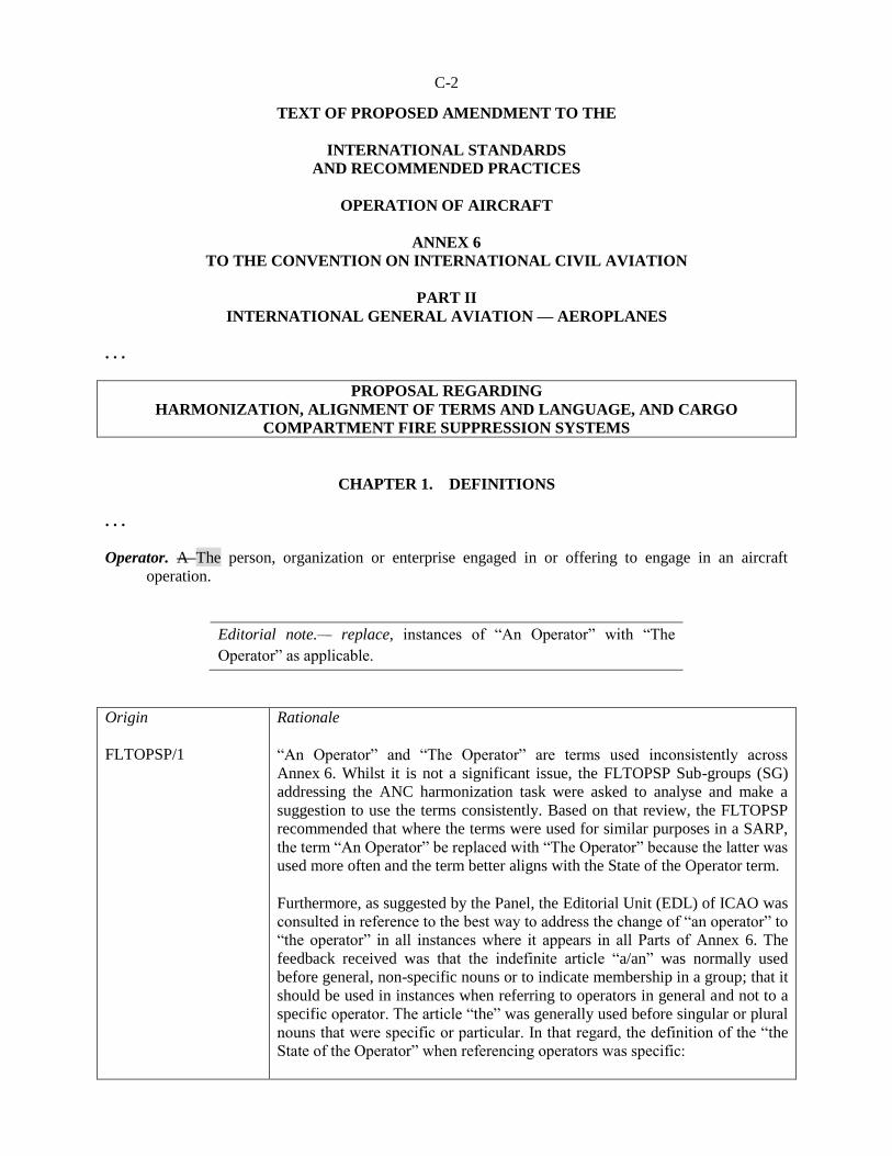
Operator. A The person, organization or enterprise engaged in or offering to engage in an aircraft
operation.
Editorial note.— replace, instances of “An Operator” with “The
Operator” as applicable.
Origin
FLTOPSP/1
Rationale
“An Operator” and “The Operator” are terms used inconsistently across
Annex 6. Whilst it is not a significant issue, the FLTOPSP Sub-groups (SG)
addressing the ANC harmonization task were asked to analyse and make a
suggestion to use the terms consistently. Based on that review, the FLTOPSP
recommended that where the terms were used for similar purposes in a SARP,
the term “An Operator” be replaced with “The Operator” because the latter was
used more often and the term better aligns with the State of the Operator term.
Furthermore, as suggested by the Panel, the Editorial Unit (EDL) of ICAO was
consulted in reference to the best way to address the change of “an operator” to
“the operator” in all instances where it appears in all Parts of Annex 6. The
feedback received was that the indefinite article “a/an” was normally used
before general, non-specific nouns or to indicate membership in a group; that it
should be used in instances when referring to operators in general and not to a
specific operator. The article “the” was generally used before singular or plural
nouns that were specific or particular. In that regard, the definition of the “the
State of the Operator” when referencing operators was specific:

C-3
State of the Operator. The State in which the operator’s principal place of
business is located or, if there is no such place of business, the operator’s
permanent residence.
Based on the aforementioned, the proposal is to amend the definition of
“operator” to align it with the “the State of the Operator” and subsequently
search and replace all instances of “an operator” with “the operator” where the
above mentioned criteria is met.
…
Point of no return. The last possible geographic point at which an aeroplane aircraft can proceed to the
destination aerodrome as well as to an available en-route alternate aerodrome for a given flight.
Origin
ANC
Rationale
The PNR definition is being adjusted in all Parts of Annex 6 to accommodate
all “aircraft” instead of only “aeroplanes”.
. . .
SECTION 2
GENERAL AVIATION OPERATIONS
. . .
CHAPTER 2.2 FLIGHT OPERATIONS
. . . 2.2.3 Flight preparation
. . . 2.2.3.4 Meteorological conditions
2.2.3.4.1 A flight to be conducted in accordance with the visual flight rules VFR shall not be
commenced unless current meteorological reports or a combination of current reports and forecasts
indicate that the meteorological conditions along the route or that part of the route to be flown under the
visual flight rules VFR will, at the appropriate time, be such as to enable compliance with these rules.
. . .
2.2.3.6 Fuel and oil requirements
2.2.3.6.1 A flight shall not be commenced unless, taking into account both the meteorological
conditions and any delays that are expected in flight, the aeroplane carries sufficient fuel and oil to ensure
that it can safely complete the flight. The amount of fuel to be carried must permit: . . . c) when the flight is conducted in accordance with the visual flight rules by day VFR, flight to the
aerodrome of intended landing, and after that, have a final reserve fuel for at least 30 minutes at normal cruising altitude; or
d) when the flight is conducted in accordance with the visual flight rules by night VFR, flight to the
aerodrome of intended landing and thereafter have a final reserve fuel for at least 45 minutes at normal cruising altitude.

C-4
Origin
FLTOPSP/1
Rationale
VFR is a term included in “Abbreviations and Symbols”.
. . .
CHAPTER 2.5 AEROPLANE COMMUNICATION AND
NAVIGATION EQUIPMENT
2.5.1 Communication equipment
. . .
2.5.1.3 An aeroplane to be operated in accordance with the visual flight rules, VFR, but as a
controlled flight, shall, unless exempted by the appropriate authority, be provided with radio
communication equipment capable of conducting two-way communication at any time during flight with
such aeronautical stations and on such frequencies as may be prescribed by the appropriate authority.
. . .
2.5.2 Navigation equipment
2.5.2.1 An aeroplane shall be provided with navigation equipment which will enable it to
proceed:
a) in accordance with the flight plan; and b) in accordance with the requirements of air traffic services; except when, if not so precluded by the appropriate authority, navigation for flights under the visual flight
rules VFR is accomplished by visual reference to landmarks.
Origin
FLTOPSP/1
Rationale
VFR is a term included in “Abbreviations and Symbols”.
. . .

C-5
PROPOSAL REGARDING
UPDATED PBN PROVISIONS
CHAPTER 2.1 GENERAL
. . .
2.1.4 Specific approvals
2.1.4.1 The pilot-in-command shall not conduct operations for which a specific approval is
required unless such approval has been issued by the State of Registry. Specific approvals shall follow the
layout and contain at least the information listed in Appendix XX.
. . .
CHAPTER 2.4 AEROPLANE INSTRUMENTS, EQUIPMENT
AND FLIGHT DOCUMENTS
. . .
2.4.2 Aeroplanes on all flights
. . .
2.4.2.2 An aeroplane shall be equipped with or carry on-board:
. . . d) the following manuals, charts and information: 1) the flight manual or other documents or information concerning any operating limitations
prescribed for the aeroplane by the certificating authority of the State of Registry, required for the application of Chapter 2.3;
2) any specific approval issued by the State of Registry, if applicable, for the operation(s) to be
conducted; 2 3) current and suitable charts for the route of the proposed flight and all routes along which it is
reasonable to expect that the flight may be diverted;
Editorial note.— Renumber subsequent paragraphs accordingly.
. . .
C-6
CHAPTER 2.5 AEROPLANE COMMUNICATION AND
NAVIGATION EQUIPMENT
. . .
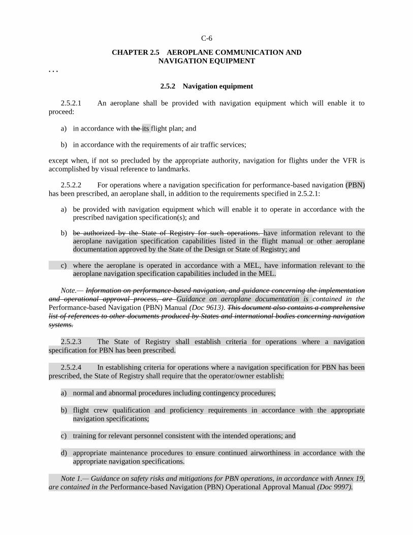
2.5.2 Navigation equipment
2.5.2.1 An aeroplane shall be provided with navigation equipment which will enable it to
proceed:
a) in accordance with the its flight plan; and b) in accordance with the requirements of air traffic services; except when, if not so precluded by the appropriate authority, navigation for flights under the VFR is
accomplished by visual reference to landmarks. 2.5.2.2 For operations where a navigation specification for performance-based navigation (PBN)
has been prescribed, an aeroplane shall, in addition to the requirements specified in 2.5.2.1: a) be provided with navigation equipment which will enable it to operate in accordance with the
prescribed navigation specification(s); and b) be authorized by the State of Registry for such operations. have information relevant to the
aeroplane navigation specification capabilities listed in the flight manual or other aeroplane documentation approved by the State of the Design or State of Registry; and
c) where the aeroplane is operated in accordance with a MEL, have information relevant to the
aeroplane navigation specification capabilities included in the MEL.
Note.— Information on performance-based navigation, and guidance concerning the implementation
and operational approval process, are Guidance on aeroplane documentation is contained in the
Performance-based Navigation (PBN) Manual (Doc 9613). This document also contains a comprehensive
list of references to other documents produced by States and international bodies concerning navigation
systems.
2.5.2.3 The State of Registry shall establish criteria for operations where a navigation
specification for PBN has been prescribed.
2.5.2.4 In establishing criteria for operations where a navigation specification for PBN has been
prescribed, the State of Registry shall require that the operator/owner establish:
a) normal and abnormal procedures including contingency procedures;
b) flight crew qualification and proficiency requirements in accordance with the appropriate
navigation specifications;
c) training for relevant personnel consistent with the intended operations; and
d) appropriate maintenance procedures to ensure continued airworthiness in accordance with the
appropriate navigation specifications.
Note 1.— Guidance on safety risks and mitigations for PBN operations, in accordance with Annex 19,
are contained in the Performance-based Navigation (PBN) Operational Approval Manual (Doc 9997).

C-7
Note 2.— Electronic navigation data management is an integral part of normal and abnormal
procedures.
2.5.2.5 The State of Registry shall issue a specific approval for complex navigation
specifications.
Note.— Guidance on specific approvals for complex navigation specifications (e.g. RNP AR) is
contained in the Performance-based Navigation (PBN) Operational Approval Manual (Doc 9997).
Editorial note.— Renumber subsequent paragraphs accordingly.
. . .
Editorial note.— Insert new Appendix 2.4 as follows:
APPENDIX 2.4 GENERAL AVIATION SPECIFIC APPROVALS
(Note. — See Section 2, Chapter 2.1, 2.1.4)
1. Purpose and scope
1.1 Specific approvals shall have a standardized format which contains the minimum information
required in the specific approval template.
Note.— When the operations to be conducted require a specific approval, a copy of the document(s)
needs to be carried on aboard (see 2.4.2.2 ).

C-8
2. Specific approval template
SPECIFIC APPROVAL
ISSUING AUTHORITY and CONTACT DETAILS1
Issuing Authority1 __________________________________
Address ________________________________________
Signature: _______________________ Date2: __________________
Telephone: ______________________ Fax: ______________________ E-mail: _______________________
OWNER/OPERATOR
Name3: ___________________________ Address: ________________________________________
Telephone: ______________________ Fax: ______________________ E-mail: _______________________
Aircraft model4 and registration marks:
SPECIFIC APPROVAL YES NO DESCRIPTION5 REMARKS
Low visibility operations
Approach and landing ☐ ☐ CAT6: _____ RVR: _____ m DH: _____ ft
Take-off ☐ ☐ RVR7: _____ m
Operational credit(s) ☐ ☐ 8
RVSM ☐ ☐
Complex navigation
specifications for PBN
operations
☐ ☐ 9
Other 10
☐ ☐
Notes.—
1. Civil aviation authority name and contact details, including the telephone country code and email if available.
2. Issuance date of the specific approval (dd-mm-yyyy) and signature of the authority representative.
3. Owner or operator’s name and address.
4. Insert the aeroplane make, model and series, or master series, if a series has been designated. The CAST/ICAO
taxonomy is available at: http://www.intlaviationstandards.org/.
5. List in this column the most permissive criteria for each approval or the approval type (with appropriate criteria).
6. Insert the applicable precision approach category (CAT II, IIIA, IIIB or IIIC). Insert the minimum RVR in metres and
decision height in feet. One line is used per listed approach category.
7. Insert the approved minimum take-off RVR in metres. One line per approval may be used if different approvals are
granted.
8. List the airborne capabilities (i.e. automatic landing, HUD, EVS, SVS, CVS) and associated operational credit(s)
granted.
9. Performance-based navigation (PBN): one line is used for each complex PBN navigation specification approval (e.g.
RNP AR APCH), with appropriate limitations listed in the “Description” column.
\.
10. Other specific approvals or data can be entered here, using one line (or one multi-line block) per approval (e.g.
specific approach operations approval, MNPS).
C-9
End of new text
Origin
FLTOPSP/1
Rationale
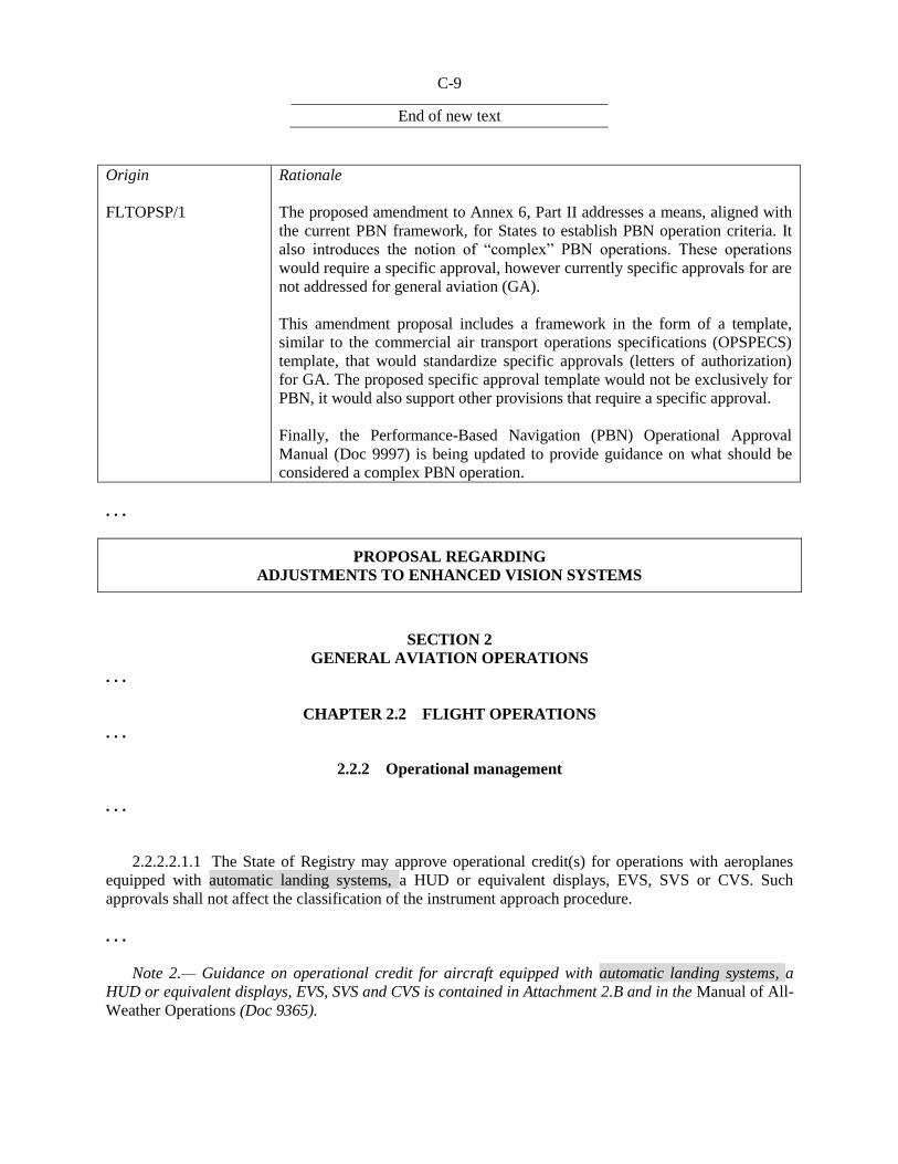
The proposed amendment to Annex 6, Part II addresses a means, aligned with
the current PBN framework, for States to establish PBN operation criteria. It
also introduces the notion of “complex” PBN operations. These operations
would require a specific approval, however currently specific approvals for are
not addressed for general aviation (GA).
This amendment proposal includes a framework in the form of a template,
similar to the commercial air transport operations specifications (OPSPECS)
template, that would standardize specific approvals (letters of authorization)
for GA. The proposed specific approval template would not be exclusively for
PBN, it would also support other provisions that require a specific approval.
Finally, the Performance-Based Navigation (PBN) Operational Approval
Manual (Doc 9997) is being updated to provide guidance on what should be
considered a complex PBN operation.
. . .
PROPOSAL REGARDING
ADJUSTMENTS TO ENHANCED VISION SYSTEMS
SECTION 2
GENERAL AVIATION OPERATIONS
. . .
CHAPTER 2.2 FLIGHT OPERATIONS
. . .
2.2.2 Operational management
. . .
2.2.2.2.1.1 The State of Registry may approve operational credit(s) for operations with aeroplanes
equipped with automatic landing systems, a HUD or equivalent displays, EVS, SVS or CVS. Such
approvals shall not affect the classification of the instrument approach procedure.
. . .
Note 2.— Guidance on operational credit for aircraft equipped with automatic landing systems, a
HUD or equivalent displays, EVS, SVS and CVS is contained in Attachment 2.B and in the Manual of All-
Weather Operations (Doc 9365).
C-10
Origin
FLTOPSP/1
Rationale
The amendment to paragraph 2.2.2.2.1.1 brings automatic landing systems
from Section 3 in this way the provision would apply to all GA aeroplanes.
. . .
CHAPTER 2.4 AEROPLANE INSTRUMENTS, EQUIPMENT
AND FLIGHT DOCUMENTS
. . .
2.4.15 Aeroplanes equipped with automatic landing systems, a head-up display (HUD) or equivalent displays, enhanced vision systems (EVS),
synthetic vision systems (SVS) and/or combined vision systems (CVS)
2.4.15.1 Where aeroplanes are equipped with automatic landing systems, a HUD or equivalent
displays, EVS, SVS or CVS, or any combination of those systems into a hybrid system, criteria for the
use of such systems for the safe operation of an aeroplane shall be established by the State of Registry.
. . .
2.4.15.2 In approving the operational establishing operational criteria for the use of automatic
landing systems, a HUD or equivalent displays, EVS, SVS or CVS, the State of Registry shall ensure that:
a) the equipment meets the appropriate airworthiness certification requirements;
b) the operator/owner has carried out a safety risk assessment of associated with the operations supported by the automatic landing systems, a HUD or equivalent displays, EVS, SVS or CVS;
c) the operator/owner has established and documented the procedures for the use of, and training
requirements for automatic landing systems, a HUD or equivalent displays, EVS, SVS or CVS.
Note 1.— Guidance on safety risk assessments is contained in the Safety Management Manual
(SMM) (Doc 9859).
Note 2.— Guidance on establishing operational approvals criteria is contained in Attachment 2.B.
Origin
FLTOPSP/1
Rationale
The amendments to 2.4.15 are required for consistency within the paragraph
and to meet the original intent of Amendment 33 to Annex 6, Part II. It is also
consistent with the language used for the EFB SARPs which were introduced
with Amendment 33 to Annex 6, Part II and brings automatic landing systems
from Section 3 so the provision would apply to all GA aeroplanes.
. . .
C-11
ATTACHMENT 2.B
AUTOMATIC LANDING SYSTEMS, HEAD-UP DISPLAY (HUD),
EQUIVALENT DISPLAYS AND VISION SYSTEMS
Supplementary to 2.2.2.2, and 2.4.15.1, 3.4.2.7 and 3.6.12
Introduction
The material in this attachment provides guidance for certified automatic landing systems, HUD,
equivalent displays and vision systems intended for operational use in aircraft engaged in international air
navigation. A HUD, vision These systems and hybrid systems may be installed and operated to reduce
workload, improve guidance, enhance reduce flight technical error and enhance situational awareness
and/or to obtain an operational credit by establishing minima below the aerodrome operating minima, for
approach ban purposes, or reducing the visibility requirements or requiring fewer ground facilities as
compensated for by airborne capabilities. credits. Automatic landing systems, HUD, equivalent displays
and vision systems may be installed separately or together as part of a hybrid system. Any operational
credit to be obtained from for their use requires a specific approval from the State of Registry.
Note 1.— “Vision systems” is a generic term referring to the existing systems designed to provide
images, i.e. enhanced vision systems (EVS), synthetic vision systems (SVS) and combined vision systems
(CVS).
Note 2.— Operational credit can be granted only within the limits of the design airworthiness
approval.
Note 3.— Currently, operational credit has been given only to vision systems containing an image
sensor providing a real-time image of the actual external scene on the a HUD.
Note 4.— More detailed information and guidance on automatic landing systems, HUD, equivalent
displays and vision systems are contained in the Manual of All-Weather Operations (Doc 9365.). This
manual should be consulted in conjunction with this Attachment.
1. HUD and equivalent displays
1.1 General
1.1.1 A HUD presents flight information into the pilot’s forward external field of view without
significantly restricting that external view.
1.1.2 A variety of flight Flight information may should be presented on a HUD depending on, or an
equivalent display, as required for the intended flight operation, flight conditions, systems capabilities and
operational approval. A HUD may include, but is not limited to, the following:use.
a) airspeed;
b) altitude;
c) heading;
d) vertical speed;

C-12
e) angle of attack;
f) flight path or velocity vector;
g) attitude with bank and pitch references;
h) course and glide path with deviation indications;
i) status indications (e.g. navigation sensor, autopilot, flight director); and
j) alerts and warning displays (e.g. ACAS, wind shear, ground proximity warning).
1.2 Operational applications
1.2.1 Flight operations with a HUD can improve situational awareness by combining flight
information located on head-down displays with the external view to provide pilots with more immediate
awareness of relevant flight parameters and situation information while they continuously view the
external scene. This improved situational awareness can also reduce errors in flight operations and
improve the pilot’s ability to transition between instrument and visual references as meteorological
conditions change. Flight operations applications may include the following:
a) enhanced situational awareness during all flight operations, but especially during taxi, take-off,
approach and landing;
b) reduced flight technical error during take-off, approach and landing; and
c) improvements in performance due to precise prediction of touchdown area, tail strike
awareness/warning and rapid recognition of and recovery from unusual attitudes.
1.2.2 A HUD may be used for the following purposes:
a) to supplement conventional flight deck instrumentation in the performance of a particular task or
operation. The primary cockpit instruments remain the primary means for manually controlling or
manoeuvring the aircraft; and
b) or as a primary flight display;
1) information presented by the HUD may be used by the pilot in lieu of scanning head-down
displays. Operational approval of a HUD for such use allows the pilot to control the aircraft
by reference to the HUD for approved ground or flight operations; and
2) information presented by the HUD may be used as a means to achieve additional navigation
or control performance. The required information is displayed on the HUD. Operational
credit, in the form of lower minima, for a HUD used if certified for this purpose may be
approved for a particular aircraft or automatic flight control system. Additional credit may
also be allowed when conducting HUD operations in situations where automated systems are
otherwise used.

C-13
1.2.3 A An approved HUD, as a stand-alone system, may:
a) qualify for operations with reduced visibility or reduced RVR; or
b) replace some parts of the ground facilities such as touchdown zone and/or centre line lights.
Examples and references to publications in this regard can be found in the Manual of All-Weather
Operations (Doc 9365).
1.2.4 A The functions of a HUD may be provided by a suitable equivalent display is one that has at
least the following characteristics: it has a head-up presentation not requiring transition of visual attention
from head down to head up; it displays sensor-derived imagery conformal to the pilot’s external view; it
permits simultaneous view of the EVS sensor imagery, required aircraft flight symbology, and the
external view; and its display characteristics and dynamics are suitable for manual control of the aircraft. ,
however . However, before such systems can be used, the appropriate airworthiness and operational
approvals approval should be obtained.
1.3 HUD training
1.3.1 Training and recent experience requirements for operations using HUD or equivalent displays
should be established, monitored and approved by the State of the Operator or the State of Registry for
general aviation. Training requirements should include requirements for recent experience if the State
determines that these requirements are significantly different than the current requirements for the use of
conventional head-down instrumentation.
1.3.2 HUD The training should address all flight operations for which the HUD is designed and
operationally approved. Some training elements may require adjustments based on whether the aeroplane
has a single or dual HUD installation. Training should include contingency procedures required in the
event of head-up or equivalent display degradation or failure. HUD training should include the following
elements as applicable to the intended use: is used.
a) an understanding of the HUD, its flight path, energy management concepts and symbology. This
should include operations during critical flight events (e.g. ACAS traffic advisory/resolution
advisory, upset and wind shear recovery, engine or system failure);
b) HUD limitations and normal procedures, including maintenance and operational checks
performed to ensure normal system function prior to use. These checks include pilot seat
adjustment to attain and maintain appropriate viewing angles and verification of HUD operating
modes;
c) HUD use during low visibility operations, including taxi, take-off, instrument approach and
landing in both day and night conditions. This training should include the transition from head-
down to head-up and head-up to head-down operations;
d) failure modes of the HUD and the impact of the failure modes or limitations on crew
performance;
e) crew coordination, monitoring and verbal call-out procedures for single HUD installations with
head-down monitoring for the pilot not equipped with a HUD and head-up monitoring for the
pilot equipped with a HUD;
f) crew coordination, monitoring and verbal call-out procedures for dual HUD installations with use
of a HUD by the pilot flying the aircraft and either head-up or head-down monitoring by the other

C-14
pilot;
g) consideration of the potential for loss of situational awareness due to “tunnel vision” (also known
as cognitive tunnelling or attention tunnelling);
h) any effects that weather, such as low ceilings and visibilities, may have on the performance of a
HUD; and
i) HUD airworthiness requirements.
2. Vision systems
2.1 General
2.1.1 Vision systems can display electronic real-time images of the actual external scene achieved
through the use of image sensors (EVS) , i.e. EVS, or display synthetic images, which are derived from
the on-board avionic systems (SVS) , i.e. SVS. Vision systems can also consist of a combination of these
two systems or called combined vision systems (CVS). Such a system may display electronic real-time
images of the external scene using the EVS component of the system. However, the merging of EVS and
SVS into a CVS is dependent on the intended function (e.g. whether or not there is intent to achieve
operational credit). The information from vision systems may be displayed head-up and/or head-down.
Operational credit, which may be granted to vision systems, is currently only applicable when real-time
image information is displayed head-up.
2.1.2 The information from vision systems may be displayed on a head-up or head-down display.
When enhanced vision imagery is displayed on a HUD, it should be presented to the pilot’s forward
external field of view without significantly restricting that external view.
2.1.3 The enhanced position fixing and guidance provided by SVS may provide additional safety
for all phases of flight especially low visibility taxi, take-off, approach and landing operations.
2.1.4 Light emitting diode (LED) lights may not be visible to infrared-based vision systems due to
the fact that LED lights are not incandescent and they do not have a significant heat signature. Operators
of such vision systems will need to acquire information about the LED implementation programmes at
aerodromes where they operate. intend to operate. More details about the consequences of LED lights are
contained in the Manual of All-Weather Operations (Doc 9365).
2.2 Operational applications
2.2.1 Flight operations with enhanced vision image sensors EVS allow the pilot to view an image of
the external scene obscured by darkness or other visibility restrictions. When the external scene is
partially obscured, enhanced vision imaging may The use of EVS will also allow the pilot to acquire
acquisition of an image of the external scene earlier than with natural or , unaided vision, hence providing
for a smoother transition to references by natural vision. The improved acquisition of an image of the
external scene may improve situational awareness. It may also qualify for operational credit if the
information from the vision system is presented to the pilots in a suitable way and the necessary
airworthiness approval and specific approval by the State of Registry have been obtained for the
combined system.

C-15
2.2.2 Vision system imagery may also allow enable pilots to detect other aircraft on the ground,
terrain or obstructions on the runway or adjacent to runways or taxiways. A vision system image can also
provide visual cues to enable earlier runway alignment and a more stabilized approach.
2.2.3 The combined display of aircraft performance, guidance and imagery may allow the pilot to
maintain a more stabilized approach and smoothly transition from enhanced visual references to natural
visual references.
2.3 Vision systems training
2.3.1 Training requirements should be established, monitored and approved by the State of the
Operator. Training requirements should include recency of experience requirements if the State of the
Operator determines that these requirements are significantly different than the current requirements for
the use of a HUD without enhanced vision imagery or conventional head-down instrumentation.
2.3.2 Training should address all flight operations for which the vision system is approved. This
training should include contingency procedures required in the event of system degradation or failure.
Training for situational awareness should not interfere with other required operations. Training for
operational credit should also require training on the applicable HUD used to present the enhanced visual
imagery. Training should include the following elements as applicable:
a) an understanding of the system characteristics and operational constraints;
b) normal procedures, controls, modes and system adjustments (e.g. sensor theory including radiant
versus thermal energy and resulting images);
c) operational constraints, normal procedures, controls, modes and system adjustments;
d) limitations;
e) airworthiness requirements;
f) vision system display during low visibility operations, including taxi, take-off, instrument
approach and landing; system use for instrument approach procedures in both day and night
conditions;
g) failure modes and the impact of failure modes or limitations upon crew performance, in
particular, for two-pilot operations;
h) crew coordination and monitoring procedures and pilot call-out responsibilities;
i) transition from enhanced imagery to visual conditions during runway visual acquisition;
j) rejected landing: with the loss of visual cues of the landing area, touchdown zone or rollout area;
k) any effects that weather, such as low ceilings and visibilities, may have on the performance of the
vision system; and
l) effects of aerodrome lighting using LED lights.
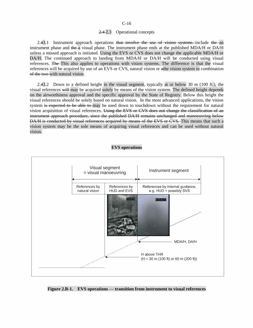
C-16
Visual segment= visual manoeuvring
Instrument segment
MDA/H, DA/H
H above THR
(H = 30 m (100 ft) or 60 m (200 ft))
References bynatural vision
References byHUD and EVS
2.4 2.3 Operational concepts
2.43.1 Instrument approach operations that involve the use of vision systems include the an
instrument phase and the a visual phase. The instrument phase ends at the published MDA/H or DA/H
unless a missed approach is initiated. Using the EVS or CVS does not change the applicable MDA/H or
DA/H. The continued approach to landing from MDA/H or DA/H will be conducted using visual
references. The This also applies to operations with vision systems. The difference is that the visual
references will be acquired by use of an EVS or CVS, natural vision or athe vision system in combination
of the two with natural vision.
2.43.2 Down to a defined height in the visual segment, typically at or below 30 m (100 ft.), the
visual references will may be acquired solely by means of the vision system. The defined height depends
on the airworthiness approval and the specific approval by the State of Registry. Below this height the
visual references should be solely based on natural vision. In the most advanced applications, the vision
system is expected to be able to may be used down to touchdown without the requirement for natural
vision acquisition of visual references. Using the EVS or CVS does not change the classification of an
instrument approach procedure, since the published DA/H remains unchanged and manoeuvring below
DA/H is conducted by visual references acquired by means of the EVS or CVS. This means that such a
vision system may be the sole means of acquiring visual references and can be used without natural
vision.
EVS operations
Figure 2.B-1. EVS operations — transition from instrument to visual references

C-17
2.4 Vision systems training
2.4.3 In addition to the operational credit that EVS/CVS is able to provide, these systems may also
provide an operational and safety advantage through improved situational awareness, earlier acquisition
of visual references and smoother transition to references by natural vision. These advantages are more
pronounced for Type A approach operations than for Type B approach operations.
2.4.1 Training and recent experience requirements should be established, by the State of Registry.
Training should address all flight operations for which the vision system is used.
2.5 Visual references
2.5.1 The In principle the required visual references do not change due to the use of an EVS or
CVS, but those references are allowed to be acquired by means of either the vision system until a certain
height during the approach (see Figure 2.B-1) as described in paragraph 2.3.2.
2.5.2 In regions In States that have developed requirements for operations with vision systems, the
use of visual references have been regulated and examples of this are indicated provided in Table 2.B-1
the Manual of All-Weather Operations (Doc 9365).
3. Hybrid systems
3.1 A hybrid system generically means that two or more systems are combined. The hybrid system
typically has improved performance compared to each of the component systems, which in turn may
qualify for operational credit. Vision systems are normally part The inclusion of a hybrid system, e.g.
EVS is typically combined with a HUD. Including more components systems in the hybrid system
normally enhances the performance of the system. The Manual of All-Weather Operations (Doc 9365)
contains some examples of hybrid systems.
3.2 Table 2.B-2 provides some examples of hybrid system components. Any combination of the
listed systems may constitute a hybrid system. The degree of operational credit that may be given to a
hybrid system depends on its performance (accuracy, integrity and availability) as assessed and
determined by the certification and operational approval processes.
Figure 2.B-1. EVS operations — transition from instrument to visual references
4. Operational credits
4.1 Aerodrome operating minima are expressed in terms of minimum visibility/RVR and MDA/H
or DA/H. With respect to operational credit this means that the visibility/RVR requirements, established
in the instrument approach procedure, may be reduced or satisfied for aircraft equipped with appropriately
approved vision systems such as EVS. Reasons for granting operational credit may be when aircraft are
better equipped than what was originally considered when designing the instrument approach procedure
or when runway visual aids considered in the design of the procedure are not available but can be
compensated for by on-board equipment When aerodrome operating minima are established, the
combined capability of the aircraft equipment and on-ground infrastructure should be taken into account.
Better equipped aircraft may be able to operate into lower natural visibility conditions, lower DA/H
and/or operate with less ground infrastructure. Operational credit means that the aerodrome operating
minima may be reduced in case of suitably equipped aircraft. Another way to grant operational credit is to

C-18
allow visibility requirements to be fulfilled, wholly or partly, by means of the on-board systems. HUD,
automatic landing or vision systems were not available at the time when the criteria for aerodrome
operating minima were originally established.
4.2 Credits related to visibility/RVR can be given using at least three concepts. The first concept is
to reduce the required RVR which will allow the aircraft to continue the approach beyond the approach
ban point with a reported RVR lower than what was established for the approach procedure. Where a
minimum visibility is prescribed, a second concept to grant operational credit may be used. In this case,
the required minimum visibility is kept unchanged, but it is satisfied by means of the on-board equipment,
typically an EVS. The result of both these concepts is that operations are allowed in meteorological
conditions where otherwise they would not be possible. A third concept is to give operational credit by
allowing operations in visibility/RVR which are not lower than those established for the approach
procedure, but the approach operation is conducted with less facilities on the ground. One example of the
latter is to allow Category II operations without touchdown and/or centre line lights, compensated for by
additional on-board equipment, e.g. a HUD.
4.3 Granting operational credits does not affect the classification of an instrument approach
procedure since, as described in Standard 2.2.2.2.2, instrument approach procedures are designed to
support a given instrument approach operation (i.e. type, category). However, the design of those
procedures may not take into consideration on-board equipment that may compensate for facilities on the
ground.
Table 2.B-1. Examples of operational credits
OPERATIONS BELOW DA/DH OR MDA/MDH
Example 1 Example 2
For procedures designed to support Type A
operations, the following visual references for the
intended runway should be distinctly visible and
identifiable:
• the approach lighting system; or
• the runway threshold, identified by at least one
of the following:
— the beginning of the runway landing surface;
— threshold lights; or
— runway end identifier lights; and
• the touchdown zone, identified by at least one of
the following:
— the runway touchdown zone landing surface;
— touchdown zone lights;
— touchdown zone markings; or
— runway lights.
For procedures designed to support 3D Type A and
Type B CAT I operations, the following visual
references should be displayed and identifiable to
the pilot on the EVS image:
• elements of the approach lighting system; or
• the runway threshold, identified by at least one
of the following:
— the beginning of the runway landing surface;
— threshold lights;
— threshold identification lights; or
— the touchdown zone, identified by at least
one of the following:
– the runway touchdown zone landing
surface;
– touchdown zone lights;
– touchdown zone markings; or
– runway lights.
Operations below 60 m (200 ft)
above touchdown zone elevation
Operations below 60 m (200 ft)
above threshold elevation
No additional requirements apply at 60 m (200 ft). For procedures designed to support 3D Type A

C-19
operations, the visual references are the same as
those specified below for Type B CAT I operations.
Operations below 30 m (100 ft)
above touchdown zone elevation
Operations below 30 m (100 ft)
above threshold elevation
The visibility should be sufficient for the following
to be distinctly visible and identifiable to the pilot
without reliance on the EVS:
• the lights or markings of the threshold; or
• the lights or markings of the touchdown zone.
For procedures designed to support Type B CAT II
operations, at least one of the visual references
specified below should be distinctly visible and
identifiable to the pilot without reliance on the
EVS:
• the lights or markings of the threshold; or
• the lights or markings of the touchdown zone.
Table 2.B-2. Examples of hybrid system components
Systems based on image sensors Systems not based on image sensors
EVS
• Passive infrared sensors
• Active infrared sensors
• Passive millimetre wave radiometer
• Active millimetre wave radar
SVS
Autoflight systems, flight control computers,
automatic landing systems
Systems for position fixing
CVS (where the EVS component as above qualifies
for operational credit)
CVS (the SVS component)
HUD, equivalent display
ILS, GNSS
4.4 In order to provide optimum service, the ATS may have to be informed about the capabilities of
the better-equipped aircraft, e.g. which is the minimum RVR required.
4.5 In addition to the operational credit that a HUD, vision systems and hybrid systems are able to
provide, these systems will also provide an operational and safety advantage through improved situational
awareness, earlier acquisition of visual references and smoother transition to references by natural vision.
These advantages are more pronounced for 3D Type A approach operations than for Type B approach
operations.
4.2 The granting of operational credits does not affect the classification (i.e. Type or Category) of
an instrument approach procedure since they are designed to support instrument approach operations
conducted with aircraft with the minimum equipment prescribed.
4.3 The relation between the procedure design and the operation can be described as follows. The
OCA/H is the end product of the procedure design, which does not contain any RVR or visibility values.
Based on the OCA/H and all the other elements such as available runway visual aids, the operator will
establish MDA/H or DA/H and RVR/visibility, i.e. the aerodrome operating minima. The values derived
should not be less than those that may be prescribed by the State of the Aerodrome.

C-20
5. Operational procedures
5.1 It is not prohibited to use vision systems in connection with circling. However, due to the
system layout of a vision system and the nature of a circling procedure, key visual references can be
obtained only by natural vision, and operational credit is not feasible for existing vision systems. The
vision system may provide additional situational awareness.
5.25.1 The In accordance with 2.4.15.2, the operator should develop suitable operational procedures
associated with the use of an auto-land system, a HUD or an equivalent display, vision systems and
hybrid systems. These procedures should be included in the operations manual. The instructions in the
operations manual should include and cover at least the following:
a) any limitation that is imposed by the airworthiness or operational approvals;
b) how operational credit affects:
1) flight planning with respect to destination and alternate aerodromes;
2) ground operations;
3) flight execution, e.g. approach ban and minimum visibility;
4) crew resource management that takes into account the equipment configuration, e.g. the pilots
may have different presentation equipment;
5) standard operating procedures, e.g. use of autoflight systems, call-outs that may be particular
to the vision system or hybrid system, criteria for stabilized approach;
6) ATS flight plans and radio communication.
a) limitations;
b) operational credits;
c) flight planning;
d) ground and airborne operations;
e) crew resource management;
f) standard operating procedures; and
g) ATS flight plans and communication.
6. Approvals
6.1 General
Note.— When the application for a specific approval relates to operational credits for systems not
including a vision system, the guidance on approvals in this attachment may be used to the extent
applicable as determined by the State of Registry.

C-21
6.1.1 An operator that wishes to conduct operations with an automatic landing system, a HUD or
equivalent display, vision system or hybrid system will need to obtain meet certain criteria and in some
instances obtain specific approvals (see Annex 6, Part I, 4.2.8.1.1 and 6.23, and the corresponding
requirements in Annex 6, Parts II and III Annex 6, Part II, 2.2.2.2 and 2.4.15). The extent of the approvals
will depend on the intended operation and the complexity of the equipment.
6.1.2 Enhanced vision imagery Systems may be used to improve situational awareness without a
specific operational approval. However, the standard operating procedures for these types of operations
need to systems should be specified in the operations manual. or equivalent document. An example of this
type of operation may include an EVS or an SVS on a head-down display that is used only for situational
awareness of the surrounding area of the aircraft during ground operations where the display is not in the
pilot’s primary field of view. For enhanced situational awareness, the installation and operational
procedures need to ensure that the operation of the vision system does not interfere with normal
procedures or the operation or use of other aircraft systems. In some cases, modifications to these normal
procedures for other aircraft systems or equipment may be necessary to ensure compatibility.
6.1.3 When a vision system or a hybrid system with vision systems imagery is used for operational
credit, operational approvals will typically require that the imagery be combined with flight guidance and
presented on a HUD. Operational approvals may require that this information also be presented on a
head-down display. Operational credit may be applied for any flight operation, but credit for instrument
approach and take-off operations is most common.
6.1.4 When the application for approval relates to operational credits for systems not including a
vision system, the guidance in this attachment may be used to the extent applicable as determined by the
State of the Operator or the State of Registry for general aviation.
6.1.5 Operators should be aware that some States may require some information about the
operational credit(s) which has been granted by the State of the Operator or the State of Registry for
general aviation. Typically the approval from that State will have to be presented, and in some cases the
State of the Aerodrome may wish to issue an approval or to validate the original approval.
6.1.3 Annex 6, Part II, 2.2.2.2.1.1 states that operational credits based on the use of an automatic
landing system, a HUD, an equivalent display, EVS, SVS or CVS or any combination of those systems
into a hybrid system, should be specifically approved.
6.1.4 The Standard in Annex 6, Part II, 2.4.15 requires the State of Registry to establish criteria for
the use of automatic landing system, a HUD, an equivalent display, EVS, SVS or CVS or any
combination of those systems into a hybrid system “for the safe operation of an aeroplane” and specifies
such criteria. When operational credits are granted by the State of Registry per Standard in Annex 6,
Part II, 2.2.2.2.1.1, the use of that system becomes essential for the safety of those operations and
approval of the use of such systems is part of the operational credit specific approval. The use of these
systems solely for enhanced situational awareness, reduced flight technical error and/or reduced workload
is an important safety feature, but does not require a specific approval.
6.1.5 Any operational credit that has been granted should be reflected in the specific approval
template and be carried on board the particular aeroplane.

C-22
6.2 Approvals Specific approvals for operational credit
6.2.1. To obtain operational credit the operator will need to specify the desired operational credit
and submit a suitable an application in accordance with 2.1.4 of Annex 6, Part II. The content of a
suitable application should include:
a) Applicant details. required for all approval requests. The official name and any business or
trading name(s), address, mailing address, e-mail address and contact telephone/fax numbers of
the applicant.
Note.— For AOC holders, the company name, AOC number and e-mail address should be
required.
b) Aircraft details. required for all approval requests. Aircraft make(s), model(s) and registration
mark(s).
c) Operator’s vision system compliance list. The contents of the compliance list are included in
Table 2.B-3.the Manual of All-Weather Operations (Doc 9365).The compliance list should
include the information that is relevant to the approval requested and the registration marks of the
aircraft involved. If more than one type of aircraft/fleet is included in a single application a
completed compliance list should be included for each aircraft/fleet.
d) Documents to be included with the application. Copies of all documents referred to in column 4
of which the operator's vision system compliance list (Table 2.B-3) operator has made references
should be included when returning in the completed application form to the civil aviation
authority. There should be no need to send complete manuals; only the relevant sections/pages
should be required. Additional guidance material can be found in the Manual of All-Weather
Operations (Doc 9365).
e) Name, title and signature.
Table 2.B-3. Example of an AOC vision system compliance list
Main heading
Expanded areas to be
addressed by the application Sub-requirements
Operator’s
operations
manual
reference or
document
reference
1.0 Reference documents
used in compiling the
submission
The submission should be
based on current up-to-date
regulatory material.
A compliance statement
showing how the criteria of the
applicable regulations and
requirements have been
satisfied.
2.0 Aircraft flight manual
(AFM)
A copy of the relevant AFM
entry showing the aircraft
certification basis for the

C-23
Main heading
Expanded areas to be
addressed by the application Sub-requirements
Operator’s
operations
manual
reference or
document
reference
vision system and any
operational conditions.
3.0 Feedback and reporting
of significant problems
An outline of the process for
the reporting of failures in the
operational use of procedures.
Note.— In particular,
significant problems with the
vision system/HUD system,
reporting on circumstances/
locations where the vision
system was unsatisfactory.
4.0 Instrument approach
chart provider and
operating minima
The name of the provider of
the relevant instrument
approach charts. Confirmation
that all aerodrome operating
minima are established in
accordance with criteria
specified by the relevant
authority.
5.0 Operations manual
entries and standard
operating procedures
Manufacturer/operator-
developed.
Manufacturer’s procedures are
recommended as a starting
point and should include at
least the items in the sub-
requirements column.
Definitions.
Check that crew members are
qualified for vision
system/HUD operations.
MEL handling.
Equipment required for vision
system operations.
Types of approach where vision
systems can be used.
Statement that the
autopilot/flight director should
be used whenever possible.
Minimum visual references for
landing.
Approach ban and RVR.
Stabilized approach criteria.
Correct seating and eye
position.
Crew coordination, e.g. duties
of the pilot flying and the
pilot not flying:
• limitations;
• designation of handling and
non-handling pilots;

C-24
Main heading
Expanded areas to be
addressed by the application Sub-requirements
Operator’s
operations
manual
reference or
document
reference
• use of automatic flight
control system;
• checklist handling;
• approach briefing;
• radio communications
handling;
• monitoring and cross-
checking of instruments and
radio aids; and
• use of the repeater display by
the pilot not flying.
Contingency procedures
including:
• failures above and below
decision height;
• ILS deviation warnings;
• autopilot disconnect;
• auto-throttle disconnect;
• electrical failures;
• engine failure;
• failures and loss of visual
references at or below
decision height;
• vision system/HUD failure
below normal decision
height;
• wind shear;
• ACAS warnings;
• EGPWS warnings.
6.0 Safety risk assessment
Operator’s safety risk
assessment.
6.2.2 The following items should be covered in a vision systems compliance list:
a) reference documents used in compiling the submission for approval;
b) flight manual;
c) feedback and reporting of significant problems;
d) requested operational credit and resulting aerodrome operating minima;
e) operations manual (or an equivalent document) entries including MEL (where applicable) and
standard operating procedures;

C-25
f) safety risk assessment;
g) training programmes; and
h) continuing airworthiness.
Expanded guidance on these items is contained in the Manual of All-Weather Operations (Doc 9365).
Origin
FLTOPSP/1
Rationale
Amendment 33 to Annex 6, Part II introduced significant modifications to the
FLTOPSP proposal regarding visions systems during the adoption process. As
a result, the accompanying guidance material was no longer clear and in some
cases no longer relevant. This proposal updates the guidance material
accordingly. Furthermore, in an effort to keep guidance material in the
attachments to Annex 6 more stable, a significant portion of that material has
been transferred to the Manual of All-Weather Operations (Doc 9365).
. . .
SECTION 3
LARGE AND TURBOJET AEROPLANES
. . .
CHAPTER 3.4 FLIGHT OPERATIONS
. . .
3.4.2 Operational management
. . .
3.4.2.7 Aerodrome operating minima
. . .
3.4.2.7.2 The State of Registry may approve operational credit(s) for operations with aeroplanes
equipped with automatic landing systems, a HUD or equivalent displays, EVS, SVS or CVS. Such
approvals shall not affect the classification of the instrument approach procedure. Note 1.— Operational credit includes: a) for the purposes of an approach ban (2.2.4.1.2), a minima below the aerodrome operating
minima; b) reducing or satisfying the visibility requirements; or c) requiring fewer ground facilities as compensated for by airborne capabilities. Note 2.— Guidance on operational credit for aircraft equipped with automatic landing systems, a
HUD or equivalent displays, EVS, SVS and CVS is contained in Attachment 2.B and in the Manual of All-
Weather Operations (Doc 9365).

C-26
Note 3.— Information regarding a HUD or equivalent displays, including references to RTCA and
EUROCAE documents, is contained in the Manual of All-Weather Operations (Doc 9365).
. . .
Editorial note.— re-number subsequent paragraphs
accordingly
CHAPTER 3.6 AEROPLANE INSTRUMENTS, EQUIPMENT
AND FLIGHT DOCUMENTS
. . .
3.6.12 Aeroplanes equipped with automatic landing systems, a head-up display (HUD) or equivalent displays, enhanced vision systems (EVS), synthetic vision systems (SVS)
and/or combined vision systems (CVS)
3.6.12.1 Where aeroplanes are equipped with automatic landing systems, a HUD or equivalent
displays, or EVS, SVS or CVS, or any combination of those systems into a hybrid system, the use of such
systems for the safe operation of an aeroplane shall be approved by the State of Registry.
Note.— Information regarding a HUD or equivalent displays, including references to RTCA and
EUROCAE documents, is contained in the Manual of All-Weather Operations (Doc 9365).
3.6.12.2 In approving the operational use of automatic landing systems, a HUD or equivalent
displays, EVS, SVS or CVS, the State of Registry shall ensure that:
a) the equipment meets the appropriate airworthiness certification requirements; b) the operator has carried out a safety risk assessment associated with the operations supported by
the automatic landing systems, a HUD or equivalent displays, EVS, SVS or CVS; c) the operator has established and documented the procedures for the use of, and training
requirements for, automatic landing systems, a HUD or equivalent displays, EVS, SVS or CVS.
Note 1.— Guidance on safety risk assessments is contained in the Safety Management Manual
(SMM) (Doc 9859).
Note 2.— Guidance on operational approvals is contained in Attachment 2.B.
Origin
FLTOPSP/1
Rationale
With the foregoing amendments, 3.4.2.7.2 and 3.6.12 are now redundant and
can be deleted in toto.
. . .
— — — — — — — —

ATTACHMENT D to State letter AN 11/1.1.30-15/9
PROPOSED AMENDMENT TO ANNEX 6, PART III
NOTES ON THE PRESENTATION OF THE AMENDMENT
The text of the amendment is arranged to show deleted text with a line through it and new text highlighted
with grey shading, as shown below:
Text to be deleted is shown with a line through it. Text to be deleted
New text to be inserted is highlighted with grey shading. New text to be inserted
Text to be deleted is shown with a line through it
followed by the replacement text which is highlighted
with grey shading.
New text to replace existing text

D-2
TEXT OF PROPOSED AMENDMENT TO THE
INTERNATIONAL STANDARDS
AND RECOMMENDED PRACTICES
OPERATION OF AIRCRAFT
ANNEX 6
TO THE CONVENTION ON INTERNATIONAL CIVIL AVIATION
PART III
INTERNATIONAL AVIATION — HELICOPTERS
. . .
PROPOSAL REGARDING
HARMONIZATION, ALIGNMENT OF TERMS AND LANGUAGE, AND CARGO
COMPARTMENT FIRE SUPPRESSION SYSTEMS
SECTION I
GENERAL
CHAPTER 1. DEFINITIONS
. . .
Operator. A The person, organization or enterprise engaged in or offering to engage in an aircraft
operation.
Editorial note.— replace, instances of “An Operator” with “The
Operator” as applicable.
Origin
FLTOPSP/1
Rationale
“An Operator” and “The Operator” are terms used inconsistently across
Annex 6. Whilst it is not a significant issue, the FLTOPSP Sub-groups (SG)
addressing the ANC harmonization task were asked to analyse and make a
suggestion to use the terms consistently. Based on that review, the FLTOPSP
recommended that where the terms were used for similar purposes in a SARP,
the term “An Operator” be replaced with “The Operator” because the latter was
used more often and the term better aligns with the State of the Operator term.
Furthermore, as suggested by the Panel, the Editorial Unit (EDL) of ICAO was
consulted in reference to the best way to address the change of “an operator” to
“the operator” in all instances where it appears in all Parts of Annex 6. The
feedback received was that the indefinite article “a/an” was normally used
before general, non-specific nouns or to indicate membership in a group; that it
should be used in instances when referring to operators in general and not to a

D-3
specific operator. The article “the” was generally used before singular or plural
nouns that were specific or particular. In that regard, the definition of the “the
State of the Operator” when referencing operators was specific:
State of the Operator. The State in which the operator’s principal place of
business is located or, if there is no such place of business, the operator’s
permanent residence.
Based on the aforementioned, the proposal is to amend the definition of
“operator” to align it with the “the State of the Operator” and subsequently
search and replace all instances of “an operator” with “the operator” where the
above mentioned criteria is met.
Point of no return. The last possible geographic point at which an aircraft can proceed to the destination
aerodrome as well as to an available en-route alternate aerodrome for a given flight.
Origin
ANC
Rationale
The definition Annex 6 Part I PNR definition, as amended in Part I and Part II
for application to “aircraft” instead of only “aeroplanes”, is being added to Part
III because the term is also used in Annex 6 Part III.
. . .
SECTION II
INTERNATIONAL COMMERCIAL AIR TRANSPORT
CHAPTER 1. GENERAL
. . .
1.1 Compliance with laws, regulations and procedures
1.1.1 Operators The operator shall ensure that their all employees when abroad know that they
must comply with the laws, regulations and procedures of the those States in which their helicopters are
operated operations are conducted.
1.1.2 Operators The operator shall ensure that all pilots are familiar with the laws, regulations
and procedures, pertinent to the performance of their duties, prescribed for the areas to be traversed, the
heliports to be used and the air navigation facilities relating thereto. The operator shall ensure that other
members of the flight crew are familiar with such of these regulations and procedures as are pertinent to
the performance of their respective duties in the operation of the helicopter.
Origin
FLTOPSP/1
Rationale
This text is currently used in Annex 6, Part I (3.1.1 and 3.1.2) for the same
purpose and is considered to be more appropriate.
. . .
D-4
1.1.3 Operators shall ensure that flight crew members demonstrate the ability to speak and
understand the language used for radiotelephony communications as specified in Annex 1.
Editorial note.— renumber subsequent
paragraphs accordingly.
. . .
1.1.8 Operators shall ensure that flight crew members demonstrate the ability to speak and
understand the language used for radiotelephony communications as specified in Annex 1.
Origin
FLTOPSP/1
Rationale
Move the text in order to harmonize with Annex 6, Part I (3.1.8).
CHAPTER 2. FLIGHT OPERATIONS
. . .
2.2 Operational certification and supervision
2.2.1 The air operator certificate
. . .
2.2.1.5 The air operator certificate shall contain at least the following information and, from
1 January 2010, shall follow the layout of Appendix 3, paragraph 2:
. . .
2.2.1.6 The operations specifications associated with the air operator certificate shall contain at
least the information listed in Appendix 3, paragraph 3, and, from 1 January 2010, shall follow the layout
of Appendix 3, paragraph 3.
Origin
FLTOPSP/1
Rationale
The applicable dates are now in the past and, therefore, they are no longer
needed.
. . .
2.2.3 Operations manual
2.2.3.1 An The operator shall make available, provide for the use and guidance of operations
personnel concerned, an operations manual constructed using the guidance contained in Attachment G.
The operations manual shall be amended or revised as is necessary to ensure that the information
contained therein is kept up to date. All such amendments or revisions shall be notified to all personnel
that are required to use this manual.

D-5
2.2.3.2 The State of the Operator shall establish a requirement for the operator to provide a copy
of the operations manual together with all amendments and/or revisions, for review and acceptance and,
where required, approval. The operator shall incorporate in the operations manual such mandatory
material as the State of the Operator may require. . . . Note 2.— Specific items in an operations manual require the approval of the State of the Operator in
accordance with the Standards in 2.2.8, 4.1.3, 7.3.1 and, 10.3 and 11.2.1.
Origin
FLTOPSP/1
Rationale
This text is currently used in Annex 6, Part I (4.2.3) for the same purpose and
is considered to be more appropriate. A reference has also been updated in the
note.
. . .
2.2.6 Checklists
The checklists provided in accordance with 4.1.4 shall be used by flight crews prior to, during and after
all phases of operations, and in emergency, to ensure compliance with the operating procedures contained
in the aircraft operating manual, the helicopter flight manual or other documents associated with the
certificate of airworthiness and otherwise in the operations manual. The design and utilization of
checklists shall observe Human Factors principles.
Origin
FLTOPSP/1
Rationale
“Helicopter Flight Manual” is considered more appropriate, to be more
explicit.
. . .
2.2.8 Heliport or landing location operating minima (operations under IFR)
Origin
FLTOPSP/1
Rationale
This text is currently used in Annex 6, Part I, 4.2.8 for the same purpose and is
considered to be more appropriate.
. . .

D-6
2.2.11 Passengers
. . .
2.2.11.3 In The operator shall ensure that in an emergency during flight, passengers shall be are
instructed in such emergency action as may be appropriate to the circumstances.
Origin
FLTOPSP/1
Rationale
This text is currently used in Annex 6, Part II (3.4.2.9.3) for the same purpose
and is considered to be more appropriate.
. . .
2.3 Flight preparation
. . .
Note.— Series of flights are consecutive flights that:
a) begin and end within a period of 24 hours; and b) are all conducted by the same pilot-in-command.
Origin
FLTOPSP/1
Rationale
Delete notes as “series of flights” is a term included in Chapter 1 –
Definitions.
. . .
2.3.4 Alternate heliports
. . .
2.3.4.2 Destination alternate heliport
2.3.4.2.1 For a flight to be conducted in accordance with IFR, at least one destination alternate
shall be specified in the operational flight plan and the flight plan, unless:
. . . b) the heliport of intended landing is isolated and no suitable alternate is available. A point of no
return (PNR) shall be determined.
. . .
2.3.4.3 Suitable offshore alternates When an offshore alternate heliport is specified, it shall be specified
subject to the following:
a) the offshore alternates alternate heliport shall be used only after a PNR. Prior to a PNR, onshore
alternates alternate heliports shall be used;
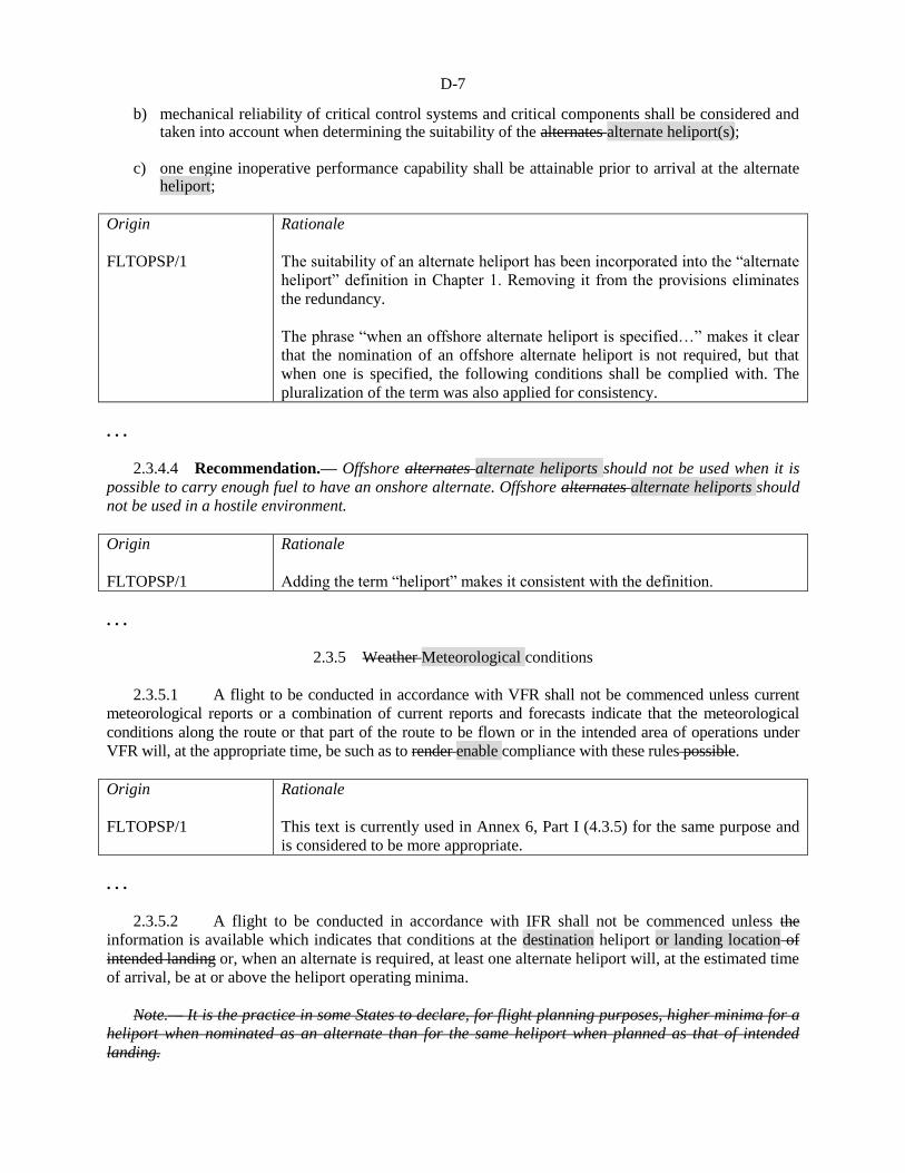
D-7
b) mechanical reliability of critical control systems and critical components shall be considered and taken into account when determining the suitability of the alternates alternate heliport(s);
c) one engine inoperative performance capability shall be attainable prior to arrival at the alternate
heliport;
Origin
FLTOPSP/1
Rationale
The suitability of an alternate heliport has been incorporated into the “alternate
heliport” definition in Chapter 1. Removing it from the provisions eliminates
the redundancy.
The phrase “when an offshore alternate heliport is specified…” makes it clear
that the nomination of an offshore alternate heliport is not required, but that
when one is specified, the following conditions shall be complied with. The
pluralization of the term was also applied for consistency.
. . .
2.3.4.4 Recommendation.— Offshore alternates alternate heliports should not be used when it is
possible to carry enough fuel to have an onshore alternate. Offshore alternates alternate heliports should
not be used in a hostile environment.
Origin
FLTOPSP/1
Rationale
Adding the term “heliport” makes it consistent with the definition.
. . .
2.3.5 Weather Meteorological conditions
2.3.5.1 A flight to be conducted in accordance with VFR shall not be commenced unless current
meteorological reports or a combination of current reports and forecasts indicate that the meteorological
conditions along the route or that part of the route to be flown or in the intended area of operations under
VFR will, at the appropriate time, be such as to render enable compliance with these rules possible.
Origin
FLTOPSP/1
Rationale
This text is currently used in Annex 6, Part I (4.3.5) for the same purpose and
is considered to be more appropriate.
. . .
2.3.5.2 A flight to be conducted in accordance with IFR shall not be commenced unless the
information is available which indicates that conditions at the destination heliport or landing location of
intended landing or, when an alternate is required, at least one alternate heliport will, at the estimated time
of arrival, be at or above the heliport operating minima.
Note.— It is the practice in some States to declare, for flight planning purposes, higher minima for a
heliport when nominated as an alternate than for the same heliport when planned as that of intended
landing.

D-8
2.3.5.3 To ensure that an adequate margin of safety is observed in determining whether or not an
approach and landing can be safely carried out at each alternate heliport or landing location, the operator
shall specify appropriate incremental values for height of cloud base and visibility, acceptable to the State
of the Operator, to be added to the operator’s established heliport or landing location operating minima.
Note.— Guidance on the selection of these incremental values is contained in the Flight Planning and
Fuel Management Manual (FPFMM) (Doc 9976).
Editorial note.— renumber subsequent
paragraphs accordingly.
Origin
FLTOPSP/1
Rationale
The paragraph was added in order to harmonize with Annex 6, Part I (4.3.5.3)
and the note is no longer be needed.
. . .
2.3.6 Fuel and oil requirements
. . .
2.3.6.3.3 When no suitable alternate heliport or landing location is available, in terms of
2.3.4.2.1 (e.g. the destination is isolated), sufficient fuel shall be carried to enable the helicopter to fly to
the destination to which the flight is planned and thereafter for a period that will, based on geographic and
environmental considerations, enable a safe landing to be made.
Origin
FLTOPSP/1
Rationale
The suitability of an alternate heliport has been incorporated into the “alternate
heliport” definition in Chapter 1. Removing it from the provisions eliminates
the redundancy.
. . .
2.4 In-flight procedures
2.4.1 Heliport operating minima
2.4.1.1 A flight shall not be continued towards the heliport of intended landing, unless the latest
available information indicates that at the expected time of arrival, a landing can be effected at that
heliport, or at least one destination alternate heliport, in compliance with the operating minima established
in accordance with 2.2.8.1.
Origin
FLTOPSP/1
Rationale
Harmonize with Annex 6, Part I (4.4.1.1)
. . .

D-9
CHAPTER 4. HELICOPTER INSTRUMENTS, EQUIPMENT,
AND FLIGHT DOCUMENTS
. . .
4.3 Flight recorders
. . .
4.3.1 Flight data recorders and aircraft data recording systems
. . .
4.3.1.2 Operation
4.3.1.2.1 All helicopters of a maximum certificated take-off mass of over 3 180 kg 3 175 kg
for which the individual certificate of airworthiness is first issued on or after 1 January 2016 shall be
equipped with a Type IVA FDR.
. . .
4.3.1.2.3 Recommendation.— All helicopters of a maximum certificated take-off mass of over
3 180 kg 3 175 kg, up to and including 7 000 kg, for which the individual certificate of airworthiness is
first issued on or after 1 January 1989, should be equipped with a Type V FDR.
4.3.1.2.4 All turbine-engined helicopters of a maximum certificated take-off mass of over 2
250 kg, up to and including 3 180 kg 3 175 kg for which the application for type certification was
submitted to a Contracting State on or after 1 January 2018 shall be equipped with:
. . .
4.3.1.2.5 Recommendation.— All helicopters of a maximum certificated take-off mass of
3 180 kg 3 175 kg or less for which the individual certificate of airworthiness is first issued on or after 1
January 2018 should be equipped with:
Origin
FLTOPSP/1
Rationale
The weight amount of “3 180 kg” and “3 175 kg” are used inconsistently in
Annex 6, Part III as the metric conversion of 7 000 lbs which is the normal
helicopter category weight limit for various risk mitigation and equipment
requirements in States using imperial units. The weight of 3 175 kg is a more
precise conversion. For consistency, therefore, all references to “3 180 kg”
should be changed to “3 175 kg”.
4.3.1.3 Discontinuation
4.3.1.3.1 The use of engraving metal foil FDRs shall be discontinued.
4.3.1.3.2 Recommendation.— The use of analogue FDRs using frequency modulation (FM)
should be discontinued.
4.3.1.3.3 The use of photographic film FDRs shall be discontinued.

D-10
4.3.1.3.4 The use of analogue FDRs using frequency modulation (FM) shall be discontinued
by 1 January 2012.
4.3.1.3.5 Recommendation.— The use of magnetic tape FDRs should be discontinued by
1 January 2011.
4.3.1.3.6 The use of magnetic tape FDRs shall be discontinued by 1 January 2016.
Origin
FLTOPSP/1
Rationale
The applicable dates are now in the past and, therefore, are no longer needed.
. . .
4.3.2 Cockpit voice recorders
4.3.2.1 Operation
. . .
4.3.2.1.2 Recommendation.— All helicopters of a maximum certificated take-off mass of over
3 180 kg 3 175 kg for which the individual certificate of airworthiness is first issued on or after 1 January
1987 should be equipped with a CVR. For helicopters not equipped with an FDR, at least main rotor
speed should be recorded on the CVR.
Origin
FLTOPSP/1
Rationale
The weight amount of “3 180 kg” and “3 175 kg” are used inconsistently in
Annex 6, Part III as the metric conversion of 7 000 lbs which is the normal
helicopter category weight limit for various risk mitigation and equipment
requirements in States using imperial units. The weight of 3 175 kg is a more
precise conversion. For consistency, therefore, all references to “3 180 kg”
should be changed to “3 175 kg”.
. . .
4.4 Instruments and equipment for flights operated under
VFR and IFR — by day and night
. . .
4.4.3 All helicopters when operating in accordance with IFR, or when the helicopter cannot be
maintained in a desired attitude without reference to one or more flight instruments, shall be equipped
with:
. . . i) a means of indicating in on the flight crew compartment deck the outside air temperature;
Origin
FLTOPSP/1
Rationale
This text is considered to be more appropriate.

D-11
. . .
4.5 All helicopters on flights over water
. . .
4.5.2 Emergency equipment
4.5.2.1 Helicopters operating in performance Class 1 or 2 and operating in accordance with the
provisions of 4.5.1 shall be equipped with: . . . b) life-saving rafts in sufficient numbers to carry all persons on board, stowed so as to facilitate their
ready use in emergency, provided with such life-saving equipment including means of sustaining life as is appropriate to the flight to be undertaken; and
Recommendation.— When two life rafts are fitted, each should be able to carry all
occupants in the overload state.
Note.— The overload state is a design safety margin of 1.5 times the maximum capacity.
c) when two life rafts are fitted, each shall be able to carry all occupants in the overload state; and
c) d) equipment for making the pyrotechnical distress signals described in Annex 2.
Note.— The life raft overload state has a design safety margin of 1.5 times the maximum capacity.
Origin
FLTOPSP/1
Rationale
Revised text. The provision has been upgraded from a Recommendation to a
Standard.
When two life rafts are fitted, one may not deploy successfully because of the
attitude of the helicopter in the water or for other reasons. Carrying two life
rafts increases the likelihood that at least one raft will deploy properly
following an uncontrolled ditching when structural damage to the aircraft
occurs. Requiring each raft in a two-raft configuration to carry all occupants in
an overload state is currently the normal practice in offshore operations and
should be mandated to improve safety and survivability.
. . .
4.8 All helicopters on high altitude flights
. . .
4.8.3 A helicopter intended to be operated at flight altitudes at which the atmospheric pressure
is less than 376 hPa, or which, if operated at flight altitudes at which the atmospheric pressure is more
than 376 hPa which cannot descend safely within four minutes to a flight altitude at which the
atmospheric pressure is equal to 620 hPa, and for which the individual certificate of airworthiness was
issued on or after 9 November 1998, shall be provided with automatically deployable oxygen equipment
to satisfy the requirements of 2.3.8.2. The total number of oxygen dispensing units shall exceed the
number of passenger and cabin crew seats by at least 10 per cent.

D-12
4.8.4 Recommendation.— A helicopter intended to be operated at flight altitudes at which the
atmospheric pressure is less than 376 hPa, or which, if operated at flight altitudes at which the
atmospheric pressure is more than 376 hPa which cannot descend safely within four minutes to a flight
altitude at which the atmospheric pressure is equal to 620 hPa, and for which the individual certificate of
airworthiness was issued before 9 November 1998, should be provided with automatically deployable
oxygen equipment to satisfy the requirements of 2.3.8.2. The total number of oxygen dispensing units
should exceed the number of passenger and cabin crew seats by at least 10 per cent.
Origin
FLTOPSP/1
Rationale
The change is proposed to harmonize Annex 6, Part III with Part I (6.7.5 and
6.7.6).
. . .
CHAPTER 5. HELICOPTER COMMUNICATION
AND NAVIGATION EQUIPMENT
. . .
Editorial note.— Insert new paragraph 5.4 as follows:
5.4 Electronic navigation data management
5.4.1 The operator shall not employ electronic navigation data products that have been
processed for application in the air and on the ground unless the State of the Operator has approved the
operator’s procedures for ensuring that the process applied and the products delivered have met
acceptable standards of integrity and that the products are compatible with the intended function of the
equipment that will use them. The State of the Operator shall ensure that the operator continues to
monitor both process and products.
Note.— Guidance relating to the processes that data suppliers may follow is contained in RTCA
DO200A/EUROCAE ED-76 and RTCA DO-201A/EUROCAE ED-77.
5.4.2 The operator shall implement procedures that ensure the timely distribution and insertion
of current and unaltered electronic navigation data to all aircraft that require it.
End of new text
Origin
FLTOPSP/1
Rationale
The new text is proposed to harmonize Part III with Part I (7.4).
. . .

D-13
CHAPTER 7. HELICOPTER FLIGHT CREW
. . .
7.3 Flight crew member training programmes
7.3.1 An The operator shall establish and maintain a ground and flight training programme,
approved by the State of the Operator, which ensures that all flight crew members are adequately trained
to perform their assigned duties. The training programme shall:
. . . f) shall include training in knowledge and skills related to the operational use of head-up display
and/or enhanced vision systems for those helicopters so equipped; and g) be given on a recurrent basis, as determined by the State of the Operator and shall include an
examination to determine assessment of competence.
Origin
FLTOPSP/1
Rationale
The proposed changes to sub-paragraphs f) and g) harmonize the text in
Annex 6, Part III with that of Part I, 9.3.1 e) and g), respectively.
. . .
7.4 Qualifications
. . .
7.4.2 Pilot-in-command operational qualification
. . .
7.4.2.5 An The operator shall not continue to utilize a pilot as a pilot-in-command on an
operation in an area specified by the operator and approved by the State of the Operator unless, within the
preceding 12 months, the pilot has made at least one representative flight as a pilot member of the flight
crew, or as a check pilot, or as an observer on the flight deck. In the event that more than 12 months
elapse in which a pilot has not made such a representative flight, prior to again serving as a pilot-in-
command on that operation, that pilot must requalify in accordance with 7.4.2.2 and 7.4.2.3.
Origin
FLTOPSP/1
Rationale
The paragraph construct and intent of Annex 6 Part I, 9.4 has been harmonized
commensurate to helicopter operations. This recognizes that helicopter pilots
may need to demonstrate proficiency in skills which require multiple short
flights and are representative of specific tasks, e.g. fire extinction, precision
construction, etc.
. . .
7.4.3 Pilot proficiency checks
7.4.3.1 An The operator shall ensure that piloting technique and the ability to execute emergency
procedures is checked in such a way as to demonstrate the pilot’s competence on each type or variant of a

D-14
type of helicopter. Where the operation may be conducted under IFR, an operator shall ensure that the
pilot’s competence to comply with such rules is demonstrated to either a check pilot of the operator or to
a representative of the State of the Operator. Such checks shall be performed twice within any period of
one year. Any two such checks which are similar and which occur within a period of four consecutive
months shall not alone satisfy this requirement.
Note 1.— Flight simulation training devices approved by the State of the Operator may be used for
those parts of the checks for which they are specifically approved.
Note 2.— See the Manual of Criteria for the Qualification of Flight Simulation Training Devices
(Doc 9625).
Origin
FLTOPSP/1
Rationale
Insert new Note 2 text to harmonize with Annex 6, Part I, 9.4.4
. . .
CHAPTER 10. CABIN CREW
10.1 Assignment of emergency duties
An The operator shall establish, to the satisfaction of the State of the Operator, the minimum number of
cabin crew required for each type of helicopter, based on seating capacity or the number of passengers
carried, which shall not be less than the minimum number established during certification, in order to effect
a safe and expeditious evacuation of the helicopter, and the necessary functions to be performed in an
emergency or a situation requiring emergency evacuation. The operator shall assign these functions for each
type of helicopter.
Origin
FLTOPSP/1
Rationale
Large helicopter AFMs normally specify when a cabin crew is required based
on the number of passengers carried. This additional condition in the Part III
Standard will help ensure that States are aware that a helicopter flight manual
cabin crew requirement may exist and that it shall be observed.
. . .
SECTION III
INTERNATIONAL GENERAL AVIATION
. . .
CHAPTER 2. FLIGHT OPERATIONS
. . .
2.6 Limitations imposed by weather conditions
2.6.1 Flight in accordance with VFR
A flight, except one of purely local character in visual meteorological conditions, to be conducted in
accordance with VFR shall not be commenced unless available current meteorological reports, or a

D-15
combination of current reports and forecasts, indicate that the meteorological conditions along the route,
or that part of the route to be flown under VFR, will, at the appropriate time, be such as to render enable
compliance with these rules possible.
Origin
FLTOPSP/1
Rationale
This text is currently used in Annex 6, Part II (2.2.3.4.1) for the same purpose
and is considered to be more appropriate.
. . .
2.7 Alternate heliports
2.7.1 For a flight to be conducted in accordance with IFR, at least one suitable alternate heliport or
landing location shall be specified in the operational flight plan and the flight plan, unless:
a) the weather conditions in 2.6.2.2 prevail; or
b) 1) the heliport or landing location of intended landing is isolated and no suitable alternate
heliport or landing location is available; and
. . .
2.8 Fuel and oil requirements
. . .
2.8.3.3 When no suitable alternate heliport or landing location is available (i.e. the heliport of
intended landing is isolated and no suitable alternate is available), to fly to the heliport to which the flight
is planned and thereafter for a period as specified by the State of the Operator.
Origin
FLTOPSP/1
Rationale
The suitability of an alternate heliport has been incorporated into the “alternate
heliport” definition in Chapter 1. Removing it from the provisions eliminates
the redundancy.
. . .
CHAPTER 4. HELICOPTER INSTRUMENTS, EQUIPMENT
AND FLIGHT DOCUMENTS
. . .
4.2 Instruments and equipment for flights operated under
VFR and IFR — by day and night
. . .
4.2.3 All helicopters, when operating in accordance with IFR, or when the helicopter cannot be
maintained in a desired attitude without reference to one or more flight instruments, shall be:

D-16
a) equipped with:
. . .
8) a means of indicating in on the flight crew compartment deck the outside air temperature;
Origin
FLTOPSP/1
Rationale
This text is considered to be more appropriate.
. . .
4.7 Flight recorders
. . .
4.7.1 Flight data recorders
. . .
4.7.1.2 Operation
4.7.1.2.1 All helicopters of a maximum certificated take-off mass of over 3 180 kg 3 175 kg
for which the individual certificate of airworthiness is first issued on or after 1 January 2016 shall be
equipped with a Type IVA FDR.
. . .
4.7.1.2.3 Recommendation.— All helicopters of a maximum certificated take-off mass of over
3 180 kg 3 175 kg, up to and including 7 000 kg, for which the individual certificate of airworthiness is
first issued on or after 1 January 1989 should be equipped with a Type V FDR.
. . .
4.7.2 Cockpit voice recorders
4.7.2.1 Operation
. . .
4.7.2.1.2 Recommendation.— All helicopters of a maximum certificated take-off mass of over
3 180 kg 3 175 kg for which the individual certificate of airworthiness is first issued on or after 1 January
1987 should be equipped with a CVR. For helicopters not equipped with an FDR, at least main rotor
speed should be recorded on the CVR.
Origin
FLTOPSP/1
Rationale
The weight amount of “3 180 kg” and “3 175 kg” are used inconsistently in
Annex 6, Part III as the metric conversion of 7 000 lbs which is the normal
helicopter category weight limit for various risk mitigation and equipment
requirements in States using imperial units. The weight of 3 175 kg is a more
precise conversion. For consistency, therefore, all references to “3 180 kg”
should be changed to “3 175 kg”.
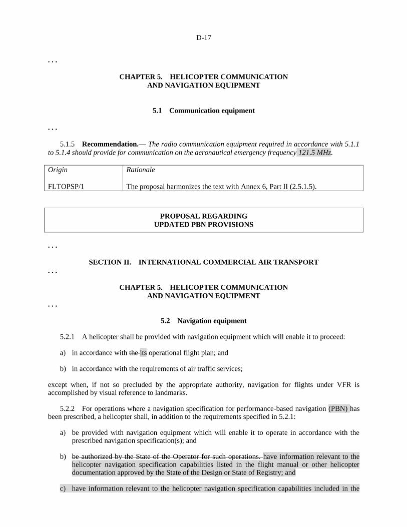
D-17
. . .
CHAPTER 5. HELICOPTER COMMUNICATION
AND NAVIGATION EQUIPMENT
5.1 Communication equipment
. . .
5.1.5 Recommendation.— The radio communication equipment required in accordance with 5.1.1
to 5.1.4 should provide for communication on the aeronautical emergency frequency 121.5 MHz.
Origin
FLTOPSP/1
Rationale
The proposal harmonizes the text with Annex 6, Part II (2.5.1.5).
PROPOSAL REGARDING
UPDATED PBN PROVISIONS
. . .
SECTION II. INTERNATIONAL COMMERCIAL AIR TRANSPORT
. . .
CHAPTER 5. HELICOPTER COMMUNICATION
AND NAVIGATION EQUIPMENT
. . .
5.2 Navigation equipment 5.2.1 A helicopter shall be provided with navigation equipment which will enable it to proceed: a) in accordance with the its operational flight plan; and b) in accordance with the requirements of air traffic services; except when, if not so precluded by the appropriate authority, navigation for flights under VFR is accomplished by visual reference to landmarks. 5.2.2 For operations where a navigation specification for performance-based navigation (PBN) has been prescribed, a helicopter shall, in addition to the requirements specified in 5.2.1:
a) be provided with navigation equipment which will enable it to operate in accordance with the prescribed navigation specification(s); and
b) be authorized by the State of the Operator for such operations. have information relevant to the
helicopter navigation specification capabilities listed in the flight manual or other helicopter documentation approved by the State of the Design or State of Registry; and
c) have information relevant to the helicopter navigation specification capabilities included in the

D-18
MEL. Note.— Information on performance-based navigation, and guidance concerning the implementation and operational approval process, are Guidance on helicopter documentation is contained in the Performance-based Navigation (PBN) Manual (Doc 9613). This document also contains a comprehensive list of references to other documents produced by States and international bodies concerning navigation systems. 5.2.3 The State of the Operator shall, for operations where a navigation specification for PBN has been prescribed, ensure that the operator has established and documented:
a) normal and abnormal procedures including contingency procedures; b) flight crew qualification and proficiency requirements in accordance with the appropriate
navigation specifications;
c) a training programme for relevant personnel consistent with the intended operations; and
d) appropriate maintenance procedures to ensure continued airworthiness in accordance with
appropriate navigation specifications. Note 1.— Guidance on safety risks and mitigations for PBN operations, in accordance with Annex 19, are contained in the Performance-based Navigation (PBN) Operational Approval Manual (Doc 9997). Note 2.— Electronic navigation data management is an integral part of normal and abnormal procedures.
5.2.4 The State of the Operator shall issue a specific approval for complex navigation
specifications.
Note .— Guidance on specific approvals for complex navigation specifications (e.g. RNP AR) is contained in the Performance-based Navigation (PBN) Operational Approval Manual (Doc 9997).
Editorial note.— Renumber subsequent paragraphs accordingly.
. . .
SECTION III. INTERNATIONAL GENERAL AVIATION
CHAPTER 1. GENERAL
. . .
1.4 Specific approvals
1.4.1 The pilot-in-command shall not conduct operations for which a specific approval is required
unless such approval has been issued by the State of Registry. Specific approvals shall follow the layout
and contain at least the information listed in Appendix XX.
. . .
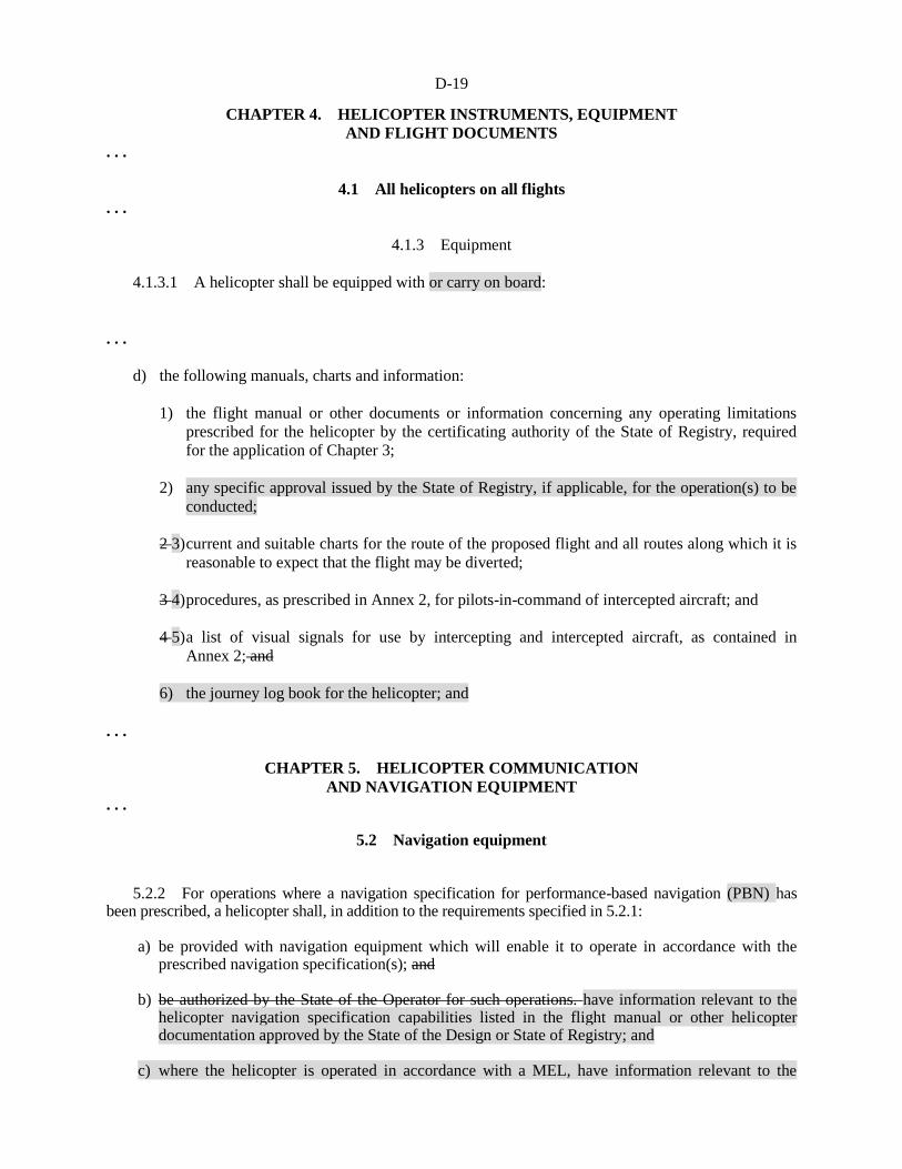
D-19
CHAPTER 4. HELICOPTER INSTRUMENTS, EQUIPMENT
AND FLIGHT DOCUMENTS
. . .
4.1 All helicopters on all flights
. . .
4.1.3 Equipment
4.1.3.1 A helicopter shall be equipped with or carry on board:
. . .
d) the following manuals, charts and information:
1) the flight manual or other documents or information concerning any operating limitations
prescribed for the helicopter by the certificating authority of the State of Registry, required
for the application of Chapter 3;
2) any specific approval issued by the State of Registry, if applicable, for the operation(s) to be
conducted;
2 3) current and suitable charts for the route of the proposed flight and all routes along which it is
reasonable to expect that the flight may be diverted;
3 4) procedures, as prescribed in Annex 2, for pilots-in-command of intercepted aircraft; and
4 5) a list of visual signals for use by intercepting and intercepted aircraft, as contained in
Annex 2; and
6) the journey log book for the helicopter; and
. . .
CHAPTER 5. HELICOPTER COMMUNICATION
AND NAVIGATION EQUIPMENT . . .
5.2 Navigation equipment 5.2.2 For operations where a navigation specification for performance-based navigation (PBN) has been prescribed, a helicopter shall, in addition to the requirements specified in 5.2.1:
a) be provided with navigation equipment which will enable it to operate in accordance with the prescribed navigation specification(s); and
b) be authorized by the State of the Operator for such operations. have information relevant to the
helicopter navigation specification capabilities listed in the flight manual or other helicopter documentation approved by the State of the Design or State of Registry; and
c) where the helicopter is operated in accordance with a MEL, have information relevant to the

D-20
helicopter navigation specification capabilities included in the MEL. Note.— Information on performance-based navigation and associated procedures, and guidance concerning the implementation and operational approval process, are Guidance on helicopter documentation is contained in the Performance-based Navigation (PBN) Manual (Doc 9613). This document also contains a comprehensive list of references to other documents produced by States and international bodies concerning navigation systems.
5.2.3 The State of Registry shall establish criteria for operations where a navigation specification
for PBN has been prescribed.
5.2.4 In establishing criteria for operations where a navigation specification for PBN has been
prescribed, the State of Registry shall require that the operator/owner establish:
a) normal and abnormal procedures including contingency procedures;
b) flight crew qualification and proficiency requirements in accordance with the appropriate
navigation specifications;
c) training for relevant personnel consistent with the intended operations; and
d) appropriate maintenance procedures to ensure continued airworthiness in accordance with the
appropriate navigation specifications.
Note 1.— Guidance on safety risks and mitigations for PBN operations, in accordance with Annex 19, are contained in the Performance-based Navigation (PBN) Operational Approval Manual (Doc 9997). Note 2.— Electronic navigation data management is an integral part of normal and abnormal procedures.
5.2.5 The State of Registry shall issue a specific approval for complex navigation specifications.
Note.— Guidance on specific approvals for complex navigation specifications (e.g. RNP AR) is
contained in the Performance-based Navigation (PBN) Operational Approval Manual (Doc 9997).
Editorial note.— Renumber subsequent
paragraphs accordingly.
. . .
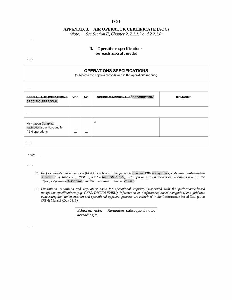
D-21
APPENDIX 3. AIR OPERATOR CERTIFICATE (AOC)
(Note. — See Section II, Chapter 2, 2.2.1.5 and 2.2.1.6)
. . .
3. Operations specifications
for each aircraft model
. . .
OPERATIONS SPECIFICATIONS (subject to the approved conditions in the operations manual)
. . .
SPECIAL AUTHORIZATIONS
SPECIFIC APPROVAL
YES NO SPECIFIC APPROVALS9 DESCRIPTION
9 REMARKS
. . .
Navigation Complex
navigation specifications for
PBN operations
13
. . .
Notes.—
. . .
13. Performance-based navigation (PBN): one line is used for each complex PBN navigation specification authorization
approval (e.g. RNAV 10, RNAV 1, RNP 4 RNP AR APCH), with appropriate limitations or conditions listed in the
“Specific Approvals Description” and/or “Remarks” columns column.
14. Limitations, conditions and regulatory basis for operational approval associated with the performance-based
navigation specifications (e.g. GNSS, DME/DME/IRU). Information on performance-based navigation, and guidance
concerning the implementation and operational approval process, are contained in the Performance-based Navigation
(PBN) Manual (Doc 9613).
Editorial note.— Renumber subsequent notes accordingly.
. . .

D-22
Editorial note.— Insert new Appendix xx as follows:
APPENDIX XX. GENERAL AVIATION SPECIFIC APPROVALS
(Note. — See Section III, Chapter 1, 1.4)
1. Purpose and scope
1.1 Specific approvals shall have a standardized format which contains the minimum information
required in the specific approval template.
Note.— When the operations to be conducted require a specific approval, a copy of the document(s)
needs to be carried on board (see 4.1.3.1 ).
2. Specific approval template
SPECIFIC APPROVAL
ISSUING AUTHORITY and CONTACT DETAILS1
Issuing Authority1 __________________________________
Address ________________________________________
Signature: _______________________ Date2: __________________
Telephone: ______________________ Fax: ______________________ E-mail: _______________________
OWNER/OPERATOR
Name3: ___________________________ Address: ________________________________________
Telephone: ______________________ Fax: ______________________ E-mail: _______________________
Aircraft model4 and registration marks:
SPECIFIC APPROVAL YES NO DESCRIPTION5 REMARKS
Low visibility operations
Approach and landing ☐ ☐ CAT6: _____ RVR: _____ m DH: _____ ft
Take-off ☐ ☐ RVR7: _____ m
Operational credit(s) ☐ ☐ 8
RVSM ☐ ☐
Complex navigation
specifications for PBN
operations
☐ ☐ 9
Other 11
☐ ☐
D-23
Notes.—
1. Civil aviation authority name and contact details, including the telephone country code and e-mail if available.
2. Issuance date of the specific approval (dd-mm-yyyy) and signature of the authority representative.
3. Owner or operator’s name and address.
4. Insert the helicopter make, model and series, or master series, if a series has been designated The CAST/ICAO
taxonomy is available at: http://www.intlaviationstandards.org/.
5. List in this column the most permissive criteria for each approval or the approval type (with appropriate criteria).
6. Insert the applicable precision approach category (CAT II, IIIA, IIIB or IIIC). Insert the minimum RVR in metres and
decision height in feet. One line is used per listed approach category.
7. Insert the approved minimum take-off RVR in metres. One line per approval may be used if different approvals are
granted.
8. List the airborne capabilities (i.e. automatic landing, HUD, EVS, SVS, CVS) and associated operational credit(s)
granted.
9. Performance-based navigation (PBN): one line is used for each complex PBN navigation specification approval (e.g.
RNP AR APCH), with appropriate limitations listed in the “Description” column.
10. Other specific approvals or data can be entered here, using one line (or one multi-line block) per approval (e.g.
Specific approach operations approval, MNPS).
Editorial note.— End of new text and renumber subsequent appendices accordingly.
. . .
Origin
FLTOPSP/1
Rationale
The proposed amendment to Annex 6, Part III addresses both international
commercial air transport and international general aviation helicopter
operations.
In Section II, international commercial air transport, it address a means to
approve PBN operations, aligned with the current PBN framework, in the same
manner that other provisions are approved in Annex 6 (i.e. by including them
in the operations manual which is approved by the State of the Operator). It
also introduces the notion of “complex” PBN operations. These operations
would require a specific approval (i.e. the approval would have to be included
in the OPSPECS for commercial air transport).
Furthermore, a proposal to amend the columns in the OPSPEC table are a
result of the FLTOPSP work on clarification of those ICAO SARPs which are
required to be included in the template in line with the purpose and scope
statements of Appendix 3 to Annex 6, Part III.
In Section III, international general aviation (GA), it address a means, aligned
with the current PBN framework, for States to establish PBN operation criteria.
It also introduces the notion of “complex” PBN operations. These operations
would require a specific approval, however currently specific approvals are not
addressed for GA.
This amendment proposal includes a framework in the form of a template,
similar to the commercial air transport operations specifications (OPSPECS)
template that would standardize specific approvals (letters of authorization) for
GA. The proposed specific approval template would not be exclusively for
PBN, it would also support other GA provisions that require a specific
approval.

D-24
Finally, the Performance-Based Navigation (PBN) Operational Approval
Manual (Doc 9997) is being updated to provide guidance on what should be
considered a complex PBN operation.
PROPOSAL REGARDING
ADJUSTMENTS TO ENHANCED VISION SYSTEMS
. . .
SECTION III
INTERNATIONAL GENERAL AVIATION
. . .
CHAPTER 4. HELICOPTER INSTRUMENTS, EQUIPMENT
AND FLIGHT DOCUMENTS
. . .
4.11 Helicopters equipped with automatic landing systems, a head-up display (HUD)
or equivalent displays, enhanced vision systems (EVS), synthetic vision systems (SVS)
and/or combined vision systems (CVS)
. . .
4.11.2 In approving the operational establishing operational criteria for the use of automatic landing
systems, a HUD or equivalent displays, EVS, SVS or CVS, the State of Registry shall ensure require that:
a) the equipment meets the appropriate airworthiness certification requirements;
b) the operator/owner has carried out a safety risk assessment of associated with the operations supported by the automatic landing systems, a HUD or equivalent displays, EVS, SVS or CVS;
c) the operator/owner has established and documented the requirements procedures for the use of, and training requirements for, automatic landing systems, a HUD or equivalent displays, EVS, SVS or CVS.
Note 1.— Guidance on safety risk assessments is contained in the Safety Management Manual
(SMM) (Doc 9859).
Note 2.— Guidance on establishing operational approvals criteria is contained in Attachment I.
Origin
FLTOPSP/1
Rationale
The amendments to 4.11 are required for consistency within the paragraph and
to meet the original intent of Amendment 19 to Annex 6, Part III. It is also
consistent with the language used for the EFB SARPs which were introduced
with Amendment 19.
. . .
D-25
ATTACHMENT I.
AUTOMATIC LANDING SYSTEMS, HEAD-UP DISPLAY (HUD),
EQUIVALENT DISPLAYS AND VISION SYSTEMS.
Supplementary to Section II, Chapter 2, 2.2.8.1.1, and Chapter 4, 4.16,
Section III, Chapter 2, 2.2.1.1, and Chapter 4, 4.11
Introduction
The material in this attachment provides guidance for certified automatic landing systems, HUD,
equivalent displays and vision systems intended for operational use in aircraft helicopters engaged in
international air navigation. A HUD, vision These systems and hybrid systems may be installed and
operated to reduce workload, improve guidance, enhance reduce flight technical error and enhance
situational awareness and/or obtain an operational credit by establishing minima below the heliport or
landing location operating minima, for approach ban purposes, or reducing the visibility requirements or
requiring fewer ground facilities as compensated for by airborne capabilities credits. Automatic- landing
systems, HUD, equivalent displays and vision systems may be installed separately or together as part of a
hybrid system. Any operational credit to be obtained fromfor their use by commercial air transport
operators requires a specific approval from the State of the Operator. In the case of general aviation, to
which this guidance is also applicable, approvals are granted by, and the State of Registry for general
aviation operators.
Note 1.— “Vision systems” is a generic term referring to the existing systems designed to provide
images, i.e. enhanced vision systems (EVS), synthetic vision systems (SVS) and combined vision systems
(CVS).
Note 2.— Automatic landing system-helicopter is an automatic approach using airborne systems
which provide automatic control of the flight path, to a point aligned with the landing surface, from which
the pilot can transition to a safe landing by means of natural vision without the use of automatic control.
Note 3.— Operational credit can be granted only within the limits of the design airworthiness
approval.
Note 3 4.— Currently, operational credit has been given only to vision systems containing an image
sensor providing a real-time image of the actual external scene on the a HUD.
Note 5. — More detailed information and guidance on automatic landing systems, HUD, equivalent
displays and vision systems is contained in the Manual of All-Weather Operations (Doc 9365.) This
manual should be consulted in conjunction with this Attachment 6.
1. HUD and equivalent displays
1.1 General
1.1.1 A HUD presents flight information into the pilot’s forward external field of view without
significantly restricting that external view.
D-26
1.1.2 A variety of flight Flight information may should be presented on a the HUD depending on or
an equivalent display, as required for the intended flight operation, flight conditions, systems capabilities
and operational approval. A HUD may include, but is not limited to, the following:use.
a) airspeed; b) altitude; c) heading; d) vertical speed; e) angle of attack; f) flight path or velocity vector; g) attitude with bank and pitch references; h) course and glide path with deviation indications; i) status indications (e.g. navigation sensor, autopilot, flight director); and j) alerts and warning displays (e.g. ACAS, wind shear, ground proximity warning).
1.2 Operational applications
1.2.1 Flight operations with a HUD can improve situational awareness by combining flight
information located on head-down displays with the external view to provide pilots with more immediate
awareness of relevant flight parameters and situation information while they continuously view the
external scene. This improved situational awareness can also reduce errors in flight operations and
improve the pilot’s ability to transition between instrument and visual references as meteorological
conditions change. Flight operations applications may include the following:
a) enhanced situational awareness during all flight operations, but especially during taxi, take-off,
approach and landing; b) reduced flight technical error during take-off, approach and landing; and c) improvements in performance due to precise prediction of touchdown area and rapid recognition
of and recovery from unusual attitudes.
1.2.2 A HUD may be used for the following purposes:
a) to supplement conventional flight deck instrumentation in the performance of a particular task or
operation. The primary cockpit instruments remain the primary means for manually controlling or manoeuvring the aircraft; and
b) as a primary flight display; 1) information presented by the HUD may be used by the pilot in lieu of scanning head-down
displays. Operational approval of a HUD for such use allows the pilot to control the aircraft by reference to the HUD for approved ground or flight operations; and
D-27
2) information presented by the HUD may be used as a means to achieve additional navigation or control performance. The required information is displayed on the HUD. Operational credit, in the form of lower minima, for a HUD used for this purpose may be approved for a particular aircraft or automatic flight control system. Additional credit may also be allowed when conducting HUD operations in situations where automated systems are otherwise used.
1.2.2 A HUD may be used to supplement conventional flight deck instrumentation or as a primary
flight display if certified for this purpose.
1.2.3 A An approved HUD, as a stand-alone system, may:
a) qualify for operations with reduced visibility or reduced RVR; or
b) replace some parts of the ground facilities such as touchdown zone and/or centre line lights.
Examples and references to publications in this regard can be found in the Manual of All-Weather
Operations (Doc 9365).
1.2.4 A HUD or equivalent display. is one that has at least the following characteristics: it has a
head-up presentation not requiring transition of visual attention from head down to head up; it displays
sensor-derived imagery conformal to the pilot’s external view; it permits simultaneous view of the EVS
sensor imagery, required aircraft flight symbology, and the external view; and its display characteristics
and dynamics are suitable for manual control of the aircraft. The functions of a HUD may be provided by
a suitable equivalent display. However, before such systems can be used, the appropriate airworthiness
and operational approvals approval should be obtained.
1.3 HUD training
1.3.1 Training and recent experience requirements for operations using HUD or equivalent displays
should, for commercial operators, be established, monitored and approved by the State of the Operator or
the State of Registry and for general aviation. Training requirements should include requirements for
recent experience if the operators by the State of Registry. For commercial air transport operations, the
training programmes should be approved by the State determines that these requirements are significantly
different than the current requirements for the use of conventional head-down instrumentation.
1.3.2 HUD of the Operator and the implementation of the training should be subject to oversight by
that State. The training should address all flight operations for which the HUD is designed and
operationally approved. Some training elements may require adjustments based on whether the helicopter
has a single or dual HUD installation. Training should include contingency procedures required in the
event of head-up display degradation or failure. HUD training should include the following elements as
applicable to the intended use:or the equivalent display is used.
a) an understanding of the HUD, its flight path, energy management concepts and symbology. This should include operations during critical flight events (e.g. ACAS traffic advisory/resolution advisory, upset and wind shear recovery, engine or system failure);
b) HUD limitations and normal procedures, including maintenance and operational checks performed to ensure normal system function prior to use. These checks include pilot seat adjustment to attain and maintain appropriate viewing angles and verification of HUD operating modes;
c) HUD use during low visibility operations, including taxi, take-off, instrument approach and landing in both day and night conditions. This training should include the transition from head-

D-28
down to head-up and head-up to head-down operations;
d) failure modes of the HUD and the impact of the failure modes or limitations on crew performance;
e) crew coordination, monitoring and verbal call-out procedures for single HUD installations with head-down monitoring for the pilot not equipped with a HUD and head-up monitoring for the pilot equipped with a HUD;
f) crew coordination, monitoring and verbal call-out procedures for dual HUD installations with use of a HUD by the pilot flying the aircraft and either head-up or head-down monitoring by the other pilot;
g) consideration of the potential for loss of situational awareness due to “tunnel vision” (also known as cognitive tunnelling or attention tunnelling);
h) any effects that weather, such as low ceilings and visibilities, may have on the performance of a HUD; and
i) HUD airworthiness requirements.
2. Vision systems
2.1 General
2.1.1 Vision systems can display electronic real-time images of the actual external scene
achieved through the use of image sensors, (EVS) i.e. EVS, or display synthetic images, which are
derived from the on-board avionic systems (SVS) , i.e. SVS. Vision systems can also consist of a
combination of these two systems or , called combined vision systems (CVS) , i.e. CVS. Such a system
may display electronic real-time images of the external scene using the EVS component of the system.
However, the merging of EVS and SVS into a CVS is dependent on the intended function (e.g. whether or
not there is intent to achieve operational credit). The information from vision systems may be displayed
head-up and/or head-down. Operational credit, which may be granted to vision systems, is currently only
applicable when real-time image information is displayed head-up.
2.1.2 The information from vision systems may be displayed on a head-up or head-down display.
When enhanced vision imagery is displayed on a HUD, it should be presented to the pilot’s forward
external field of view without significantly restricting that external view. 2.1.3 The enhanced position fixing and guidance provided by SVS may provide additional safety
for all phases of flight especially low visibility taxi, take-off, approach and landing operations. 2.1.4 Light emitting diode (LED) lights may not be visible to infrared-based vision systems due to
the fact that LED lights are not incandescent, and they do not have a significant heat signature. Operators
of such vision systems will need to acquire information about the LED implementation programmes at
heliports or landing location where they operate. aerodromes where they intend to operate. More details
about the consequences of LED lights are contained in the Manual of All-Weather Operations
(Doc 9365).
2.2 Operational applications

D-29
2.2.1 Flight operations with enhanced vision image sensors EVS allow the pilot to view an image of
the external scene obscured by darkness or other visibility restrictions. When the external scene is
partially obscured, enhanced vision imaging may The use of EVS will also allow the pilot to acquire
acquisition of an image of the external scene earlier than with natural or , unaided vision, hence providing
for a smoother transition to references by natural vision. The improved acquisition of an image of the
external scene may improve situational awareness. It may also qualify for operational credit if the
information from the vision system is presented to the pilots in a suitable way and the necessary
airworthiness approval and specific approval by the State of the Operator or State of Registry have been
obtained for the combined system. 2.2.2 Vision system imagery may also allow enable pilots to detect other aircraft on the ground,
terrain or obstructions on the runway or adjacent to runways or taxiways. A vision system image can also
provide visual cues to enable earlier runway alignment and a more stabilized approach. 2.2.3 The combined display of aircraft performance, guidance and imagery may allow the pilot to
maintain a more stabilized approach and smoothly transition from enhanced visual references to natural
visual references.
2.3 Vision systems training
2.3.1 Training requirements should be established, monitored and approved by the State of the
Operator. Training requirements should include recency of experience requirements if the State of the
Operator determines that these requirements are significantly different than the current requirements for
the use of a HUD without enhanced vision imagery or conventional head-down instrumentation. 2.3.2 Training should address all flight operations for which the vision system is approved. This
training should include contingency procedures required in the event of system degradation or failure.
Training for situational awareness should not interfere with other required operations. Training for
operational credit should also require training on the applicable HUD used to present the enhanced visual
imagery. Training should include the following elements as applicable: a) an understanding of the system characteristics and operational constraints; b) normal procedures, controls, modes and system adjustments (e.g. sensor theory including radiant
versus thermal energy and resulting images); c) operational constraints, normal procedures, controls, modes and system adjustments; d) limitations; e) airworthiness requirements; f) vision system display during low visibility operations, including taxi, take-off, instrument
approach and landing; system use for instrument approach procedures in both day and night conditions;
g) failure modes and the impact of failure modes or limitations upon crew performance, in
particular, for two-pilot operations; h) crew coordination and monitoring procedures and pilot call-out responsibilities; i) transition from enhanced imagery to visual conditions during runway visual acquisition; j) rejected landing: with the loss of visual cues of the landing area, touchdown zone or rollout area;

D-30
k) any effects that weather, such as low ceilings and visibilities, may have on the performance of the
vision system; and l) effects of heliport or landing location lighting using LED lights.
2.4 2.3 Operational concepts
2.4 3.1 Instrument approach operations that involve the use of vision systems include the an
instrument phase and the a visual phase. The instrument phase ends at the published MDA/H or DA/H
unless a missed approach is initiated. Using the EVS or CVS does not change the applicable MDA/H or
DA/H. The continued approach to landing from MDA/H or DA/H will be conducted using visual
references. The This also applies to operations with vision systems. The difference is that the visual
references will be acquired by use of an EVS or CVS, natural vision or a the vision system in
combination of the two with natural vision.
2.4 3.2 Down to a defined height in the visual segment, typically at or below 30 m (100 ft), the
visual references will may be acquired solely by means of the vision system. The defined height depends
on the airworthiness approval and the specific approval by the State of the Operator or State of Registry.
Below this height the visual references should be solely based on natural vision. In the most advanced
applications, the vision system is expected to be able to may be used down to touchdown without the
requirement for natural vision acquisition of visual references. Using the EVS or CVS does not change
the classification of an instrument approach procedure, since the published DA/H remains unchanged and
manoeuvring below DA/H is conducted by visual references acquired by means of the EVS or CVS This
means that such a vision system may be the sole means of acquiring visual references and can be used
without natural vision.
2.4.3 In addition to the operational credit that EVS/CVS is able to provide, these systems may also
provide an operational and safety advantage through improved situational awareness, earlier acquisition
of visual references and smoother transition to references by natural vision. These advantages are more
pronounced for Type A approach operations than for Type B approach operations.
2.4 Vision systems training
2.4.1 Training and recent experience requirements should be established by the State of the Operator
for commercial operators and the State of Registry for general aviation operators. For commercial
operators the training programmes should be approved by the State of the Operator and the
implementation of the training should be subject to oversight by that State. Training should address all
flight operations for which the vision system is used.
2.5 Visual references
2.5.1 The In principle the required visual references do not change due to the use of an EVS or
CVS, but those references are allowed to be acquired by means of either the vision system until a certain
height during the approach (see Figure I-1). as described in paragraph 2.3.2.
2.5.2 In regions States that have developed requirements for operations with vision systems, the use
of visual references have been regulated and examples of this are indicated in Table I-1 provided in the
Manual of All-Weather Operations (Doc 9365).
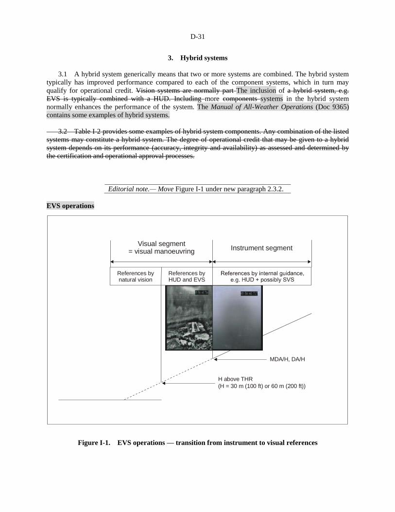
D-31
Visual segment= visual manoeuvring
Instrument segment
MDA/H, DA/H
H above THR
(H = 30 m (100 ft) or 60 m (200 ft))
References bynatural vision
References byHUD and EVS
3. Hybrid systems
3.1 A hybrid system generically means that two or more systems are combined. The hybrid system
typically has improved performance compared to each of the component systems, which in turn may
qualify for operational credit. Vision systems are normally part The inclusion of a hybrid system, e.g.
EVS is typically combined with a HUD. Including more components systems in the hybrid system
normally enhances the performance of the system. The Manual of All-Weather Operations (Doc 9365)
contains some examples of hybrid systems.
3.2 Table I-2 provides some examples of hybrid system components. Any combination of the listed
systems may constitute a hybrid system. The degree of operational credit that may be given to a hybrid
system depends on its performance (accuracy, integrity and availability) as assessed and determined by
the certification and operational approval processes.
Editorial note.— Move Figure I-1 under new paragraph 2.3.2.
EVS operations
Figure I-1. EVS operations — transition from instrument to visual references
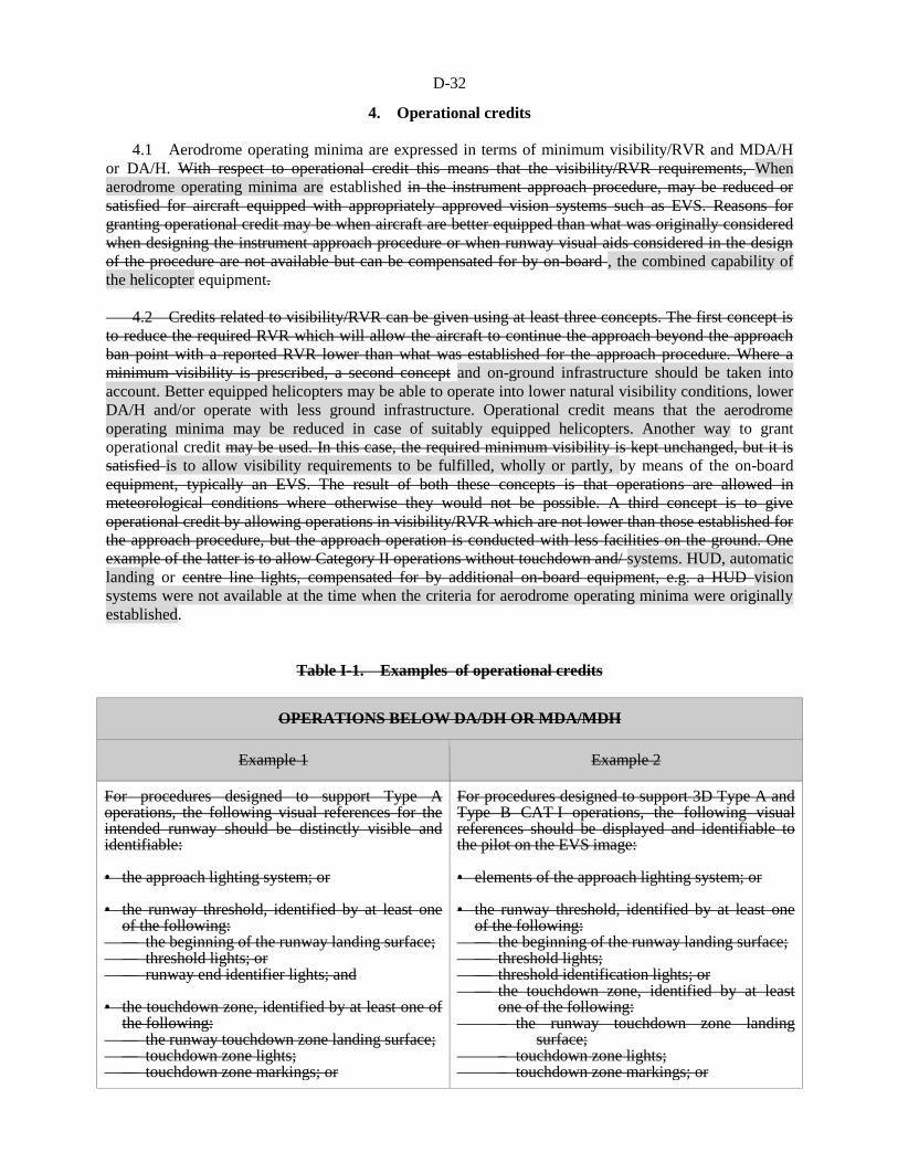
D-32
4. Operational credits
4.1 Aerodrome operating minima are expressed in terms of minimum visibility/RVR and MDA/H
or DA/H. With respect to operational credit this means that the visibility/RVR requirements, When
aerodrome operating minima are established in the instrument approach procedure, may be reduced or
satisfied for aircraft equipped with appropriately approved vision systems such as EVS. Reasons for
granting operational credit may be when aircraft are better equipped than what was originally considered
when designing the instrument approach procedure or when runway visual aids considered in the design
of the procedure are not available but can be compensated for by on-board , the combined capability of
the helicopter equipment.
4.2 Credits related to visibility/RVR can be given using at least three concepts. The first concept is
to reduce the required RVR which will allow the aircraft to continue the approach beyond the approach
ban point with a reported RVR lower than what was established for the approach procedure. Where a
minimum visibility is prescribed, a second concept and on-ground infrastructure should be taken into
account. Better equipped helicopters may be able to operate into lower natural visibility conditions, lower
DA/H and/or operate with less ground infrastructure. Operational credit means that the aerodrome
operating minima may be reduced in case of suitably equipped helicopters. Another way to grant
operational credit may be used. In this case, the required minimum visibility is kept unchanged, but it is
satisfied is to allow visibility requirements to be fulfilled, wholly or partly, by means of the on-board
equipment, typically an EVS. The result of both these concepts is that operations are allowed in
meteorological conditions where otherwise they would not be possible. A third concept is to give
operational credit by allowing operations in visibility/RVR which are not lower than those established for
the approach procedure, but the approach operation is conducted with less facilities on the ground. One
example of the latter is to allow Category II operations without touchdown and/ systems. HUD, automatic
landing or centre line lights, compensated for by additional on-board equipment, e.g. a HUD vision
systems were not available at the time when the criteria for aerodrome operating minima were originally
established.
Table I-1. Examples of operational credits
OPERATIONS BELOW DA/DH OR MDA/MDH
Example 1 Example 2
For procedures designed to support Type A operations, the following visual references for the intended runway should be distinctly visible and identifiable: • the approach lighting system; or • the runway threshold, identified by at least one
of the following: — the beginning of the runway landing surface; — threshold lights; or — runway end identifier lights; and • the touchdown zone, identified by at least one of
the following: — the runway touchdown zone landing surface; — touchdown zone lights; — touchdown zone markings; or
For procedures designed to support 3D Type A and Type B CAT I operations, the following visual references should be displayed and identifiable to the pilot on the EVS image: • elements of the approach lighting system; or • the runway threshold, identified by at least one
of the following: — the beginning of the runway landing surface; — threshold lights; — threshold identification lights; or — the touchdown zone, identified by at least
one of the following: – the runway touchdown zone landing
surface; – touchdown zone lights; – touchdown zone markings; or
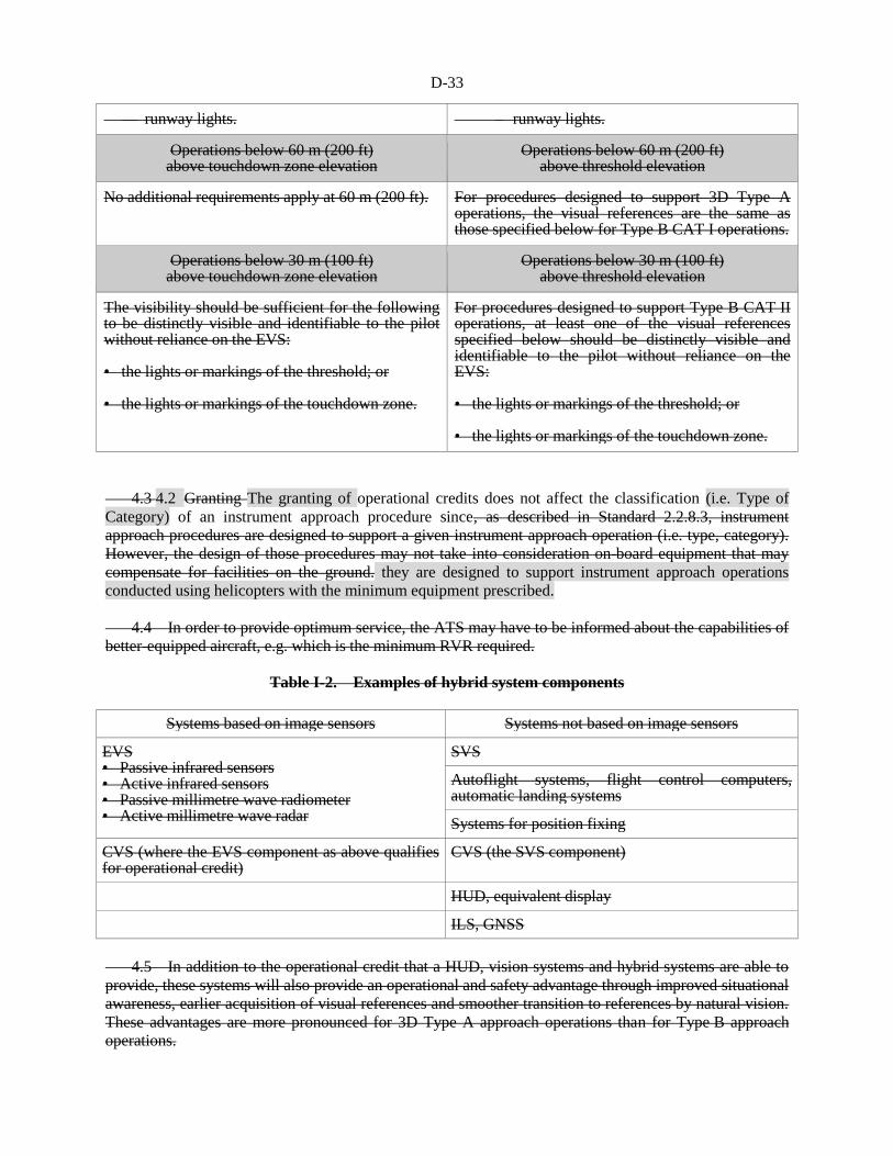
D-33
— runway lights. – runway lights.
Operations below 60 m (200 ft) above touchdown zone elevation
Operations below 60 m (200 ft) above threshold elevation
No additional requirements apply at 60 m (200 ft). For procedures designed to support 3D Type A operations, the visual references are the same as those specified below for Type B CAT I operations.
Operations below 30 m (100 ft) above touchdown zone elevation
Operations below 30 m (100 ft) above threshold elevation
The visibility should be sufficient for the following to be distinctly visible and identifiable to the pilot without reliance on the EVS: • the lights or markings of the threshold; or • the lights or markings of the touchdown zone.
For procedures designed to support Type B CAT II operations, at least one of the visual references specified below should be distinctly visible and identifiable to the pilot without reliance on the EVS: • the lights or markings of the threshold; or • the lights or markings of the touchdown zone.
4.3 4.2 Granting The granting of operational credits does not affect the classification (i.e. Type of
Category) of an instrument approach procedure since, as described in Standard 2.2.8.3, instrument
approach procedures are designed to support a given instrument approach operation (i.e. type, category).
However, the design of those procedures may not take into consideration on-board equipment that may
compensate for facilities on the ground. they are designed to support instrument approach operations
conducted using helicopters with the minimum equipment prescribed.
4.4 In order to provide optimum service, the ATS may have to be informed about the capabilities of
better-equipped aircraft, e.g. which is the minimum RVR required.
Table I-2. Examples of hybrid system components
Systems based on image sensors Systems not based on image sensors
EVS • Passive infrared sensors • Active infrared sensors • Passive millimetre wave radiometer • Active millimetre wave radar
SVS
Autoflight systems, flight control computers, automatic landing systems
Systems for position fixing
CVS (where the EVS component as above qualifies for operational credit)
CVS (the SVS component)
HUD, equivalent display
ILS, GNSS
4.5 In addition to the operational credit that a HUD, vision systems and hybrid systems are able to
provide, these systems will also provide an operational and safety advantage through improved situational
awareness, earlier acquisition of visual references and smoother transition to references by natural vision.
These advantages are more pronounced for 3D Type A approach operations than for Type B approach
operations.

D-34
4.3 The relation between the procedure design and the operation can be described as follows. The
OCA/H is the end product of the procedure design, which does not contain any RVR or visibility values.
Based on the OCA/H and all the other elements such as available runway visual aids, the operator will
establish MDA/H or DA/H and RVR/visibility, i.e. the aerodrome operating minima. The values derived
should not be less than those prescribed by the State of the Aerodrome.
5. Operational procedures
5.1 It is not prohibited to use vision systems in connection with circling. However, due to the
system layout of a vision system and the nature of a circling procedure, key visual references can be
obtained only by natural vision, and operational credit is not feasible for existing vision systems. The
vision system may provide additional situational awareness.
5.2 1 The In accordance with Section II, 4.16.2 and Section III, 4.11.2, the operator should develop
suitable operational procedures associated with the use of an automatic landing system, a HUD or an
equivalent display, vision systems and hybrid systems. The procedures should be included in the
operations manual. The instructions in the operations manual should include and cover at least the
following:
a) any limitation that is imposed by the airworthiness or operational approvals; b) how operational credit affects:
1) flight planning with respect to destination and alternate heliports or landing locations;
2) ground operations;
3) flight execution, e.g. approach ban and minimum visibility; 4) crew resource management that takes into account the equipment configuration, e.g. the pilots
may have different presentation equipment; 5) standard operating procedures, e.g. use of autoflight systems, call-outs that may be particular
to the vision system or hybrid system, criteria for stabilized approach; 6) ATS flight plans and radio communication.
a) limitations;
b) operational credits;
c) flight planning;
d) ground and airborne operations;
e) crew resource management;
f) standard operating procedures; and
g) ATS flight plans and communication.

D-35
6. Approvals
6.1 General
Note.— When the application for a specific approval relates to operational credits for systems
not including a vision system, the guidance on approvals in this attachment may be used to the extent
applicable as determined by the State of the Operator for commercial operators and the State of Registry
for general aviation operators.
6.1.1 An operator that wishes to conduct operations with an automatic landing system, a HUD or an
equivalent display, a vision system or a hybrid system will need to obtain certain approvals (see Annex 6,
Part I, 4.2.8.1.1 and 6.23, and the corresponding requirements in Annex 6, Parts II and III). as prescribed
in the relevant SARPs. The extent of the approvals will depend on the intended operation and the
complexity of the equipment. 6.1.2 Enhanced Systems that are not used for an operational credit or otherwise critical to the
aerodrome operating minima, e.g. vision imagery may be systems used to improve enhance situational
awareness may be used without a specific operational approval. However, the standard operating
procedures for these types of operations need to systems should be specified in the operations manual or
an equivalent document. An example of this type of operation may include an EVS or an SVS on a head-
down display that is used only for situational awareness of the surrounding area of the aircraft helicopter
during ground operations where the display is not in the pilot’s primary field of view. For enhanced
situational awareness, the installation and operational procedures need to ensure that the operation of the
vision system does not interfere with normal procedures or the operation or use of other aircraft systems.
In some cases, modifications to these normal procedures for other aircraft helicopter systems or
equipment may be necessary to ensure compatibility. 6.1.3 When a vision system or a hybrid system with vision systems imagery is used for operational
credit, operational approvals will typically require that the imagery be combined with flight guidance and
presented on a HUD. Operational approvals may require that this information also be presented on a
head-down display. Operational credit may be applied for any flight operation, but credit for instrument
approach and take-off operations is most common. 6.1.4 When the application for approval relates to operational credits for systems not including a
vision system, the guidance in this attachment may be used to the extent applicable as determined by the
State of the Operator or the State of Registry for general aviation. 6.1.5 Operators should be aware that some States may require some information about the
operational credit(s) which has been granted by the State of the Operator or the State of Registry for
general aviation. Typically the approval from that State will have to be presented, and in some cases the
State of the Aerodrome may wish to issue an approval or to validate the original approval.
6.1.3 The Standard in Annex 6, Part III, Section II, 4.16, requires that for commercial air
transport operations, the use of an automatic landing system, a HUD, an equivalent display, EVS, SVS or
CVS or any combination of those systems into a hybrid system, should be approved when those systems
are used “for the safe operation of a helicopter”. When operational credits have been granted by the State
of the Operator per Standard in Annex 6, Part I, 2.2.8.1.1, the use of that system becomes essential for the
safety of such operations and is subject to a specific approval. The use of these systems solely for
enhanced situational awareness, reduced flight technical error and/or reduced workload is an important
safety feature, but does not require a specific approval.
6.1.4 For commercial air transport operations, any operational credit that has been granted
should be reflected in the operation specifications for the type or individual helicopter as applicable.

D-36
6.1.5 For general aviation operations the Standard in Annex 6, Part III, Section III, 4.11
requires the State of Registry to establish criteria for the use of automatic landing system, a HUD, an
equivalent display, EVS, SVS or CVS or any combination of those systems into a hybrid system for the
safe operation of the helicopter and specifies such criteria. When operational credits are granted by the
State of Registry per Standard in Annex 6, Part III, 2.2.1.1, the use of that system becomes essential for
the safety of those operations and approval of the use of such systems is part of the operational credit
specific approval. The use of these systems solely for enhanced situational awareness, reduced flight
technical error and/or reduced workload is an important safety feature, but does not require a specific
approval.
6.1.6 For general aviation operations, any operational credit that has been granted should be
reflected in the specific approval template and be carried on board the particular helicopter.
6.2 Approvals Specific approvals for operational credit
6.2.1 To obtain an approval for operational credit, the operator will need to specify the desired
operational credit and submit a suitable application. The content of a suitable application should include: a) Applicant details. required for all approval requests. The For AOC holders, the company name,
AOC number and e-mail address. For other operators, the official name and any business or trading name(s), address, mailing address, e-mail address and contact telephone/fax numbers of the applicant.
Note.— For AOC holders, the company name, AOC number and e-mail address should be
required. b) Aircraft details.required for all approval requests. Aircraft make(s), model(s) and registration
mark(s). c) Operator’s vision system compliance list. The contents of the compliance list are included in
Table I-3 the Manual of All-Weather Operations (Doc 9365). The compliance list should include the information that is relevant to the approval requested and the registration marks of the aircraft involved. If more than one type of aircraft/fleet is included in a single application a completed compliance list should be included for each aircraft/fleet.
d) Documents to be included with the application. Copies of all documents referred to in column 4
of which the operator’s vision system compliance list (Table I-3) operator has made references should be included when returning in the completed application form to the civil aviation authority. There should be no need to send complete manuals; only the relevant sections/pages should be required. Additional guidance material can be found in the Manual of All-Weather Operations (Doc 9365).
e) Name, title and signature.
Table I-3. Example of an AOC vision system compliance list
Main heading Expanded areas to be
addressed by the application Sub-requirements
Operator’s operations
manual reference or document reference
1.0 Reference documents used in compiling the
The submission should be based on current up-to-date
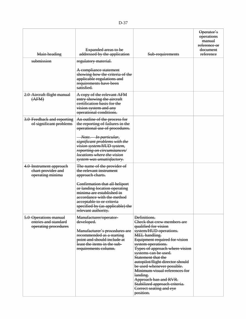
D-37
Main heading Expanded areas to be
addressed by the application Sub-requirements
Operator’s operations
manual reference or document reference
submission regulatory material. A compliance statement showing how the criteria of the applicable regulations and requirements have been satisfied.
2.0 Aircraft flight manual (AFM)
A copy of the relevant AFM entry showing the aircraft certification basis for the vision system and any operational conditions.
3.0 Feedback and reporting of significant problems
An outline of the process for the reporting of failures in the operational use of procedures. Note.— In particular, significant problems with the vision system/HUD system, reporting on circumstances/ locations where the vision system was unsatisfactory.
4.0 Instrument approach chart provider and operating minima
The name of the provider of the relevant instrument approach charts. Confirmation that all heliport or landing location operating minima are established in accordance with the method acceptable to or criteria specified by (as applicable) the relevant authority.
5.0 Operations manual entries and standard operating procedures
Manufacturer/operator-developed. Manufacturer’s procedures are recommended as a starting point and should include at least the items in the sub-requirements column.
Definitions. Check that crew members are qualified for vision system/HUD operations. MEL handling. Equipment required for vision system operations. Types of approach where vision systems can be used. Statement that the autopilot/flight director should be used whenever possible. Minimum visual references for landing. Approach ban and RVR. Stabilized approach criteria. Correct seating and eye position.

D-38
Main heading Expanded areas to be
addressed by the application Sub-requirements
Operator’s operations
manual reference or document reference
Crew coordination, e.g. duties of the pilot flying and the pilot not flying: • limitations; • designation of handling and
non-handling pilots; • use of automatic flight
control system; • checklist handling; • approach briefing; • radio communications
handling; • monitoring and cross-
checking of instruments and radio aids; and
• use of the repeater display by the pilot not flying.
Contingency procedures including: • failures above and below
decision height; • ILS deviation warnings; • autopilot disconnect; • auto-throttle disconnect; • electrical failures; • engine failure; • failures and loss of visual
references at or below decision height;
• vision system/HUD failure below normal decision height;
• wind shear; • ACAS warnings; • EGPWS warnings.
6.0 Safety risk assessment
Operator’s safety risk assessment.
6.2.2 The following items should be covered in a vision systems compliance list:
a) reference documents used in compiling the submission for approval;
b) flight manual;
c) feedback and reporting of significant problems;
d) requested operational credit and resulting aerodrome operating minima;
e) operations manual (or an equivalent document) entries including MEL (where applicable) and
standard operating procedures;

D-39
f) safety risk assessment;
g) training programmes; and
h) continuing airworthiness.
Expanded guidance on these items is contained in the Manual of All-Weather Operations
(Doc 9365).
Origin
FLTOPSP/1
Rationale
Amendment 19 to Annex 6, Part III introduced significant modifications to the
FLTOPSP proposal regarding visions systems during the adoption process. As
a result, the accompanying guidance material was no longer clear and in some
cases no longer relevant. This proposal updates the guidance material
accordingly. Furthermore, in an effort to keep guidance material in the
attachments to Annex 6 more stable, a significant portion of that material has
been transferred to the Manual of All-Weather Operations (Doc 9365)
. . .
— — — — — — — —

ATTACHMENT E to State letter AN 11/1.1.30-15/9
PROPOSED AMENDMENT TO THE PANS-ATM (DOC 4444)
NOTES ON THE PRESENTATION OF THE AMENDMENT
The text of the amendment is arranged to show deleted text with a line through it and new text highlighted
with grey shading, as shown below:
Text to be deleted is shown with a line through it. Text to be deleted
New text to be inserted is highlighted with grey shading. New text to be inserted
Text to be deleted is shown with a line through it
followed by the replacement text which is highlighted
with grey shading.
New text to replace existing text

E-2
TEXT OF PROPOSED AMENDMENT TO
PROCEDURES FOR AIR NAVIGATION SERVICES
AIR TRAFFIC MANAGEMENT
. . .
PROPOSAL REGARDING
GROUND CREW/FLIGHT CREW PHRASEOLOGIES FOR DE-/ANTI-ICING OPERATIONS
Chapter 12
PHRASEOLOGIES
. . .
12.7 GROUND CREW/FLIGHT CREW PHRASEOLOGIES
12.7.1 Ground crew/flight crew phraseologies
. . .
Editorial note.— Insert new paragraph 12.7.2 as follows:
12.7.2 De/anti-icing operations
Circumstances Phraseologies
12.7.2.1 PRIOR TO DE-ICING/ANTI-ICING
(GROUND CREW (ICEMAN) /
FLIGHT CREW)
a) STANDING BY TO DE-ICE. CONFIRM BRAKES SET
AND TREATMENT REQUIRED;
*b) [AFFIRM] BRAKES SET, REQUEST (type of
de/anti-icing treatment);
…aircraft configuration
confirmation
c) HOLD POSITION AND CONFIRM AIRCRAFT
CONFIGURED;
*d) [AFFIRM] AIRCRAFT CONFIGURED, READY FOR
DE-ICING;
e) DE-ICING STARTS NOW.
* Denotes pilot transmission.
12.7.2.2 UPON CONCLUDING
DE-ICING/ANTI-ICING
PROCEDURE
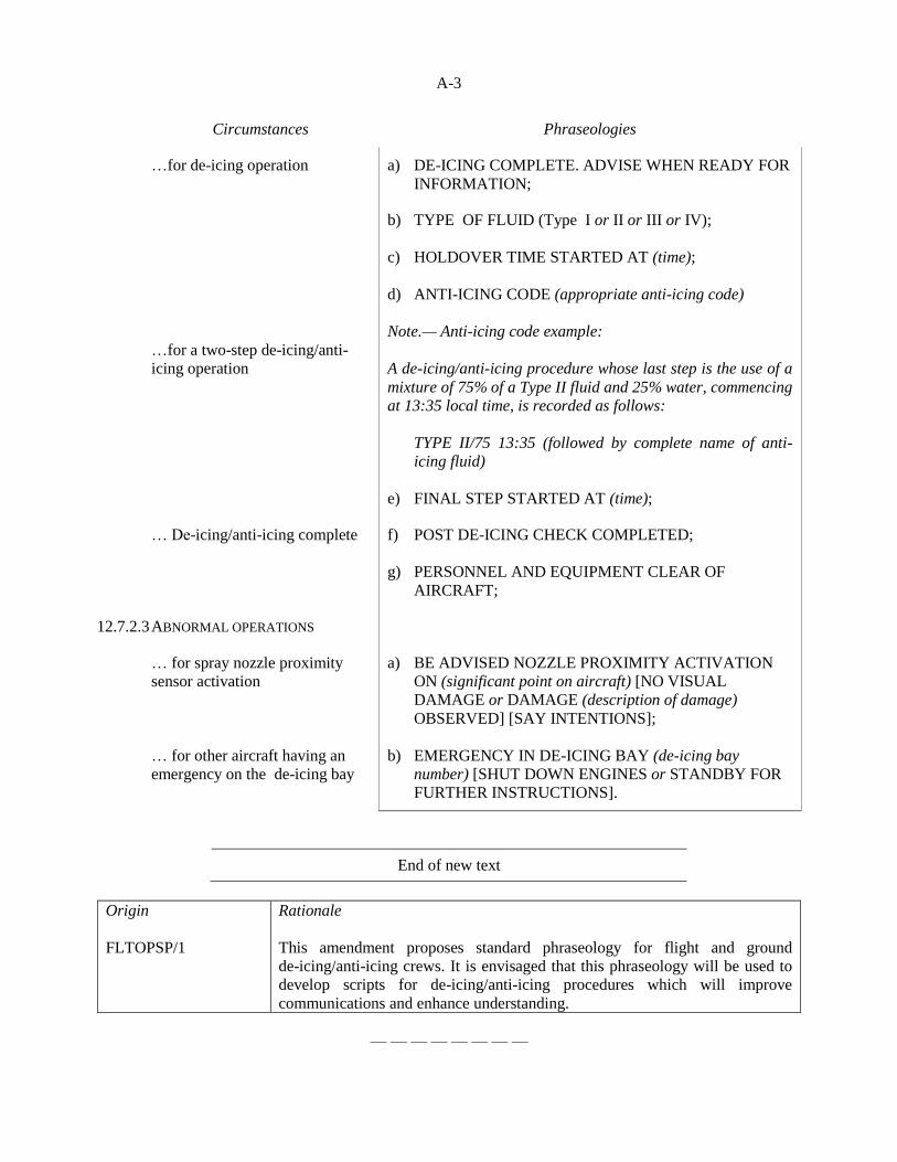
A-3
Circumstances Phraseologies
…for de-icing operation a) DE-ICING COMPLETE. ADVISE WHEN READY FOR
INFORMATION;
…for a two-step de-icing/anti-
icing operation
b) TYPE OF FLUID (Type I or II or III or IV);
c) HOLDOVER TIME STARTED AT (time);
d) ANTI-ICING CODE (appropriate anti-icing code)
Note.— Anti-icing code example:
A de-icing/anti-icing procedure whose last step is the use of a
mixture of 75% of a Type II fluid and 25% water, commencing
at 13:35 local time, is recorded as follows:
TYPE II/75 13:35 (followed by complete name of anti-
icing fluid)
e) FINAL STEP STARTED AT (time);
… De-icing/anti-icing complete f) POST DE-ICING CHECK COMPLETED;
g) PERSONNEL AND EQUIPMENT CLEAR OF
AIRCRAFT;
12.7.2.3 ABNORMAL OPERATIONS
… for spray nozzle proximity
sensor activation
… for other aircraft having an
emergency on the de-icing bay
a) BE ADVISED NOZZLE PROXIMITY ACTIVATION
ON (significant point on aircraft) [NO VISUAL
DAMAGE or DAMAGE (description of damage)
OBSERVED] [SAY INTENTIONS];
b) EMERGENCY IN DE-ICING BAY (de-icing bay
number) [SHUT DOWN ENGINES or STANDBY FOR
FURTHER INSTRUCTIONS].
End of new text
Origin
FLTOPSP/1
Rationale
This amendment proposes standard phraseology for flight and ground
de-icing/anti-icing crews. It is envisaged that this phraseology will be used to
develop scripts for de-icing/anti-icing procedures which will improve
communications and enhance understanding.
— — — — — — — —

ATTACHMENT F to State letter AN 11/1.1.30-15/9
PROPOSED AMENDMENT TO PANS-OPS, VOLUME I
NOTES ON THE PRESENTATION OF THE AMENDMENT
1. The text of the amendment is arranged to show deleted text with a line through it and new text
highlighted with grey shading, as shown below:
Text to be deleted is shown with a line through it.
text to be deleted
New text to be inserted is highlighted with grey shading.
new text to be inserted
Text to be deleted is shown with a line through it followed
by the replacement text which is highlighted with grey
shading.
new text to replace existing text

F-2
TEXT OF THE PROPOSED AMENDMENT TO
PROCEDURES FOR AIR NAVIGATION SERVICES
AIRCRAFT OPERATIONS
VOLUME I — FLIGHT PROCEDURES
PROPOSAL REGARDING
IMPROVEMENTS TO ACAS PROVISIONS
. . .
Part III
AIRCRAFT OPERATING PROCEDURES
. . .
Section 3
SECONDARY SURVEILLANCE RADAR (SSR)
TRANSPONDER OPERATING PROCEDURES
. . .
Chapter 3
OPERATION OF AIRBORNE COLLISION AVOIDANCE SYSTEM
(ACAS) EQUIPMENT
. . .
3.2 USE OF ACAS INDICATORS INDICATIONS
The indications generated by ACAS shall be used by pilots in conformity with the following safety
considerations:
. . .
c) in the event of an RA, pilots shall:
. . .
8) notify ATC when returning to the current clearance.
Note 1.— Procedures in regard to ACAS-equipped aircraft and the phraseology to be used
for the notification of manoeuvres in response to a resolution advisory are contained in the
PANS-ATM (Doc 4444), Chapters 15 and 12 respectively.
Note 2.— Where aircraft can provide automatic following of a RA when the autopilot is
engaged supported by a link between ACAS and autopilot, the operational procedures in items
4 and 8 still apply.
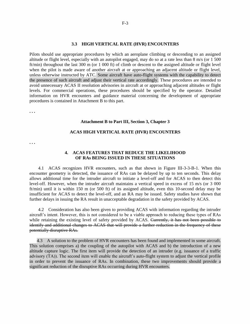
F-3
3.3 HIGH VERTICAL RATE (HVR) ENCOUNTERS
Pilots should use appropriate procedures by which an aeroplane climbing or descending to an assigned
altitude or flight level, especially with an autopilot engaged, may do so at a rate less than 8 m/s (or 1 500
ft/min) throughout the last 300 m (or 1 000 ft) of climb or descent to the assigned altitude or flight level
when the pilot is made aware of another aircraft at or approaching an adjacent altitude or flight level,
unless otherwise instructed by ATC. Some aircraft have auto-flight systems with the capability to detect
the presence of such aircraft and adjust their vertical rate accordingly. These procedures are intended to
avoid unnecessary ACAS II resolution advisories in aircraft at or approaching adjacent altitudes or flight
levels. For commercial operations, these procedures should be specified by the operator. Detailed
information on HVR encounters and guidance material concerning the development of appropriate
procedures is contained in Attachment B to this part.
. . .
Attachment B to Part III, Section 3, Chapter 3
ACAS HIGH VERTICAL RATE (HVR) ENCOUNTERS
. . .
4. ACAS FEATURES THAT REDUCE THE LIKELIHOOD
OF RAs BEING ISSUED IN THESE SITUATIONS
4.1 ACAS recognizes HVR encounters, such as that shown in Figure III-3-3-B-1. When this
encounter geometry is detected, the issuance of RAs can be delayed by up to ten seconds. This delay
allows additional time for the intruder aircraft to initiate a level-off and for ACAS to then detect this
level-off. However, when the intruder aircraft maintains a vertical speed in excess of 15 m/s (or 3 000
ft/min) until it is within 150 m (or 500 ft) of its assigned altitude, even this 10-second delay may be
insufficient for ACAS to detect the level-off, and an RA may be issued. Safety studies have shown that
further delays in issuing the RA result in unacceptable degradation in the safety provided by ACAS.
4.2 Consideration has also been given to providing ACAS with information regarding the intruder
aircraft’s intent. However, this is not considered to be a viable approach to reducing these types of RAs
while retaining the existing level of safety provided by ACAS. Currently, it has not been possible to
identify and additional changes to ACAS that will provide a further reduction in the frequency of these
potentially disruptive RAs.
4.3 A solution to the problem of HVR encounters has been found and implemented in some aircraft.
This solution comprises a) the coupling of the autopilot with ACAS and b) the introduction of a new
altitude capture logic. The first item will provide the detection of an intruder (e.g. issuance of a traffic
advisory (TA)). The second item will enable the aircraft’s auto-flight system to adjust the vertical profile
in order to prevent the issuance of RAs. In combination, these two improvements should provide a
significant reduction of the disruptive RAs occurring during HVR encounters.

F-4
Origin
FLTOPSP/1
Rationale
ACAS provides global safety benefits as a last-resort safety-net for flight
crews. However, the operational monitoring of ACAS provided information on
two main issues which affected the performance of ACAS operations namely:
a) the insufficient or inappropriate compliance with ACAS RAs by pilots;
and
b) the occurrence of unnecessary RAs for routine ATM operations due to
high vertical rate encounters.
As it was introduced in ASBU Module B0-ACAS, to deal with those issues,
this amendment proposal introduces two new optional features which can bring
significant operational and safety benefits for aircraft operations. The
performance and protection brought by ACAS are further enhanced by a new
altitude capture law that drastically reduces the number of nuisance alerts and a
new resolution advisory (RA) mode, which is coupled to the auto-pilot/flight
director to ensure accurate responses to the RAs. It is important to note that
under the new RA mode, aircraft would automatically respond to the RAs, but
at the same time, when necessary, flight crews can select a manual response to
the RAs. The benefits are reflected in ASBU B0-ACAS to encourage voluntary
equipage.
. . .
— — — — — — — —

ATTACHMENT G to State letter AN 11/1.1.30-15/9
RESPONSE FORM TO BE COMPLETED AND RETURNED TO ICAO TOGETHER
WITH ANY COMMENTS YOU MAY HAVE ON THE PROPOSED AMENDMENTS
To: The Secretary General
International Civil Aviation Organization
999 Robert-Bourassa Boulevard
Montréal, Quebec
Canada, H3C 5H7
(State)
Please make a checkmark () against one option for each amendment. If you choose options “agreement
with comments” or “disagreement with comments”, please provide your comments on separate sheets.
Agreement
without
comments
Agreement
with
comments*
Disagreement
without
comments
Disagreement
with
comments
No position
Amendment to Annex 6 — Operation of Aircraft,
Part I — International Commercial Air Transport
— Aeroplanes (Attachment B refers)
Annex 6 — Operation of Aircraft, Part II —
International General Aviation — Aeroplanes
(Attachment C refers)
Annex 6 — Operation of Aircraft, Part III —
International Operations — Helicopters
(Attachment D refers)
Procedures for Air Navigation Services — Air
Traffic Management (PANS-ATM, Doc 4444),
(Attachment E refers)
Procedures for Air Navigation Services — Aircraft
Operations (PANS-OPS, Doc 8168), Volume I —
Flight Procedures (Attachment F refers)
*“Agreement with comments” indicates that your State or organization agrees with the intent and overall
thrust of the amendment proposal; the comments themselves may include, as necessary, your reservations
concerning certain parts of the proposal and/or offer an alternative proposal in this regard.
Signature: Date:
— END —
Recommended