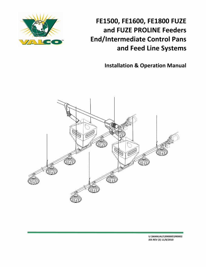
FE1500, FE1600, FE1800 FUZE and FUZE PROLINE Feeders
End/Intermediate Control Pans and Feed Line Systems
Installation & Operation Manual
U:\MANUALS\990000\990002 JDS REV (3) 11/8/2010

2
3
CONTENTS
Contents
VAL PRODUCTS, INC. WARRANTIES 5
INTRODUCTION: 8
Symbols .............................................................................................................................................................8
An Overview of Fuze Pan Feeder System ...........................................................................................................9
Feed Pan Features ........................................................................................................................................... 10
PART 1 – WINCH SYSTEM INSTALLATION 11
General Information ........................................................................................................................................ 11
System Layout – Overviews ............................................................................................................................. 11
Winch System / Suspension ............................................................................................................................. 13
Winch Installation ........................................................................................................................................... 15
Installing the Winch Cable ............................................................................................................................... 16
Screw Hook Installation ................................................................................................................................... 17
Drop Installation .............................................................................................................................................. 18
PART 2 – FUZE FEEDER 19
Feeder Assembly Overview - (applicable to all Fuze or Fuze Pro feeder assemblies) ......................................... 19
Adjusting the Feeder Settings .......................................................................................................................... 23
PART 3 – FEED LINE ASSEMBLY & SUSPENSION 24
Feed Line Assembly & Suspension ................................................................................................................... 24
PART 4 – END CONTROL PAN UNIT / Motor INSTALLATION 28
The End Control Pan Unit ................................................................................................................................ 28
Overview of Control Pan / Drive Head & Gearbox Unit Location ...................................................................... 29
Exploded Overview of End Control Pan / Direct Drive Head (Motor) & Gearbox Unit ....................................... 30
Direct Drive Head & Gearbox Installation ........................................................................................................ 31
Drive Head & Gearbox installation ................................................................................................................... 32
Detailed Assembly of Control Pan Unit ............................................................................................................ 32
PART 5 - FEED BOOT INSTALLATION 34
Boot Installation .............................................................................................................................................. 34
PART 6 – AUGER INSTALLATION 35
Auger Instructions – Important for Installing the Auger! .................................................................................. 35
Auger Brazing .................................................................................................................................................. 35
Auger Installation ............................................................................................................................................ 36

4
PART 7 – WIRING END CONTROL / DRIVE HEAD & GEARBOX UNIT 38
Wiring the Motor and Proximity Sensor ........................................................................................................... 38
Wiring Diagram ............................................................................................................................................... 40
PART 8 FEED BOOT – AUGER CONNECTION 43
PART 9 – HOPPER AND HOPPER LEVEL SWITCH ASSEMBLY 45
PART 10 – ANTI-ROOST INSTALLATION 49
PART 11 – MID-LINE CONTROL INSTALLATION 52
PART 12 - Operation Guidelines (Valco Broiler Feeding System) 53
Brood Stage, First (7-14) days: ......................................................................................................................... 53
Grow-out Stage (7-14) days to Finish: .............................................................................................................. 53
Appendix 1 – Feeder Cleaning and Maintenance 54
Appendix 2 – FE1500LS FUZE Feeder Parts List 55
Appendix 3 – FE1500RS FUZE PROLINE Feeder Parts List 56
Appendix 4– FE1500RLS FUZE PROLINE Feeder Parts List 57
Appendix 5 – FE1600RS FUZE PROLINE Feeder Parts List 58
Appendix 6 – FE1600RLS FUZE PROLINE Feeder Parts List 59
Appendix 7 – FE1800RS FUZE PROLINE Feeder Parts List 60
Appendix 8 – FE1800RLS FUZE PROLINE Feeder Parts List 61
Appendix 9 - Control Pan Exploded Drawing 62
Appendix 10 – Direct Drive Head & Gearbox Unit Parts List 64
Appendix 11- Feed Boot Parts List and Exploded Drawing 66
Appendix 12 – Replacement of Feed Boot Flighting Anchor & Parts 67
Appendix 13 - Hopper Parts List and Exploded Drawing 68
Appendix 14 - Hopper Level Switch Control 69
Appendix 15 - Winch System Replacement Parts 70
Appendix 16 - CUSTOMER SERVICE 73
5
WARRANTY
VAL PRODUCTS, INC. WARRANTIES
VAL-C0™ MANUFACTURED PRODUCTS OTHER THAN EXTENDED WARRANTY PRODUCTS
Val Products, Inc. (Val Products) warrants to the original purchaser that Val Products’ manufactured products (other than the products subject to an extended warranty set forth below) will be free of defects in material and workmanship for a period of one (1) year from and after the date of original purchase and when used in a usual and customary fashion. If Val Products is notified that such a defect exists within one year of the original purchase date and, upon inspection, agrees that the product is defective, Val Products will, at its option, (a) repair or replace (FOB Val Products’ plant) the defective product, or (b) refund to the original purchaser the original purchase price paid for the defective product less any installation, shipping, or other charges associated with the original purchase. All defective products must be returned to a Val Products designated location for evaluation. Val Products’ determination as to whether the product is defective is final. See the General Conditions and Limitations set forth below.
NIPPLE DRINKERS EXTENDED WARRANTY
Val Products, Inc. (Val Products) agrees to the following extended warranty with respect to VR Series and VL Series Nipple Drinkers manufactured by Val Products: VR Series and VL Series Nipple Drinkers that prove to be defective in workmanship or material and become unusable within a period of five (5) years from and after the date of original purchase will be repaired or replaced, at Val Products’ option, at no charge (excluding labor of removal and installation), FOB Val Products’ plant. VR Series and VL Series Nipple Drinkers which prove to be defective in workmanship or material and become unusable after five (5) years but within ten (10) years of the date of original purchase will be repaired or replaced, at Val Products’ option, at a pro rated cost basis (excluding labor of removal and installation) to the original purchaser, FOB Val Products’ plant, on the following basis: Year six (6), customer pays 50% of the current price, year seven (7), customer pays 60% of the current price, year eight (8), customer pays 70% of the current price, year nine (9), customer pays 80% of the current price, and year ten (10), customer pays 90% of the current price. All defective Nipple Drinkers must be returned to a Val Products’ designated location for evaluation. Val Products’ determination as to whether the product is defective and unusable is final. See the General Conditions and Limitations set forth below.
FIBERGLASS FAN HOUSINGS EXTENDED WARRANTY
Val Products, Inc. (Val Products) agrees to the following extended warranty with respect to the fiberglass fan housings manufactured by Val Products on VAL-CO™ PMC Power Miser 12”, 16”, 21”, 24”, 36”, 48”, and 50” Fiberglass Fans that prove to be defective in workmanship or material and become unusable over the life of the structure where the VAL-CO ™ Fiberglass Fan was originally installed after original purchase, provided that the fan has remained undisturbed in its original installation location, will be repaired or replaced, at Val Products’ option, at no charge (excluding labor of removal and installation and shipping), FOB Val Products’ plant. All defective fan housings must be returned to a Val Products’ designated location for evaluation. Val Products’ determination as to whether the product is defective and unusable is final. See the General Conditions and Limitations set forth below.
6
WARRANTY
FIBERGLASS FAN MOTORS EXTENDED WARRANTY
Val Products, Inc. (Val Products) agrees to the following extended warranty with respect to the fiberglass fan motors included as original equipment on VAL-CO™ PMC Power Miser 12”, 16”, 21”, and 24” Fiberglass Fans manufactured by Val Products that prove to be defective in workmanship or material and become unusable within a period of two (2) years from and after the date of original purchase will be repaired or replaced, at Val Products’ option, at no charge (excluding labor of removal and installation and shipping), FOB Val Products’ plant. All defective fan motors must be returned to a Val Products’ designated location for evaluation. Val Products’ determination as to whether the product is defective and unusable is final. See the General Conditions and Limitations set forth below.
General Conditions and Limitations Applicable to All Val Products, Inc. (Val Products) Warranties, Including Extended Warranties
1. The Product must be installed and operated in accordance with instructions published by Val Products or the warranty will be void.
2. Warranty will be void if all components of the product or system are not original equipment supplied by the manufacturer.
3. Products not manufactured by Val Products and supplied by outside manufacturers (such as, but not limited to, certain electrical motors, certain controls, gas valves, etc.) are warranted separately by the respective manufacturer and only to the extent of the manufacturer’s warranty.
4. Warranty applies only to products used in applications as originally intended by Val Products – other applications in industry or commerce are not covered by the Warranty. Val Products’ products are expressly not designed or authorized for use in any applications where intended to sustain or support human life or any other application where the failure of the product could result in personal injury or death.
5. Malfunctions resulting from misuse, abuse, mismanagement, negligence, alteration, accident, lack of proper maintenance, lightening strikes, electrical power surges, or electrical power interruption shall not be considered defects under the Warranty. Corrosion, material deterioration and/or equipment malfunction caused by or consistent with the excessive additions of chemicals, minerals, sediments or other foreign elements with the product shall not be considered defects under the Warranty.
6. VAL PRODUCTS WILL NOT, UNDER ANY CIRCUMSTANCES, BE LIABLE FOR ANY KIND OF SPECIAL, INCIDENTAL, CONSEQUENTIAL, OR CONTINGENT DAMAGES INCLUDING, BUT NOT LIMITED TO, LOST OR DAMAGED PRODUCT, GOODS OR LIVESTOCK, COSTS OF TRANSPORTATION, LOST SALES, LOST ORDERS, LOST INCOME, INCREASED OVERHEAD, LABOR AND INCIDENTAL COSTS AND OPERATIONAL INEFFICIENCIES. IN NO EVENT SHALL THE WARRANTY LIABILITY EXCEED THE INVOICED PRICE OF THE PRODUCT TO THE ORIGINAL PURCHASER.
7
WARRANTY
7. THE WARRANTIES SET FORTH ABOVE CONSTITUTE VAL PRODUCTS’ ENTIRE AND SOLE WARRANTY. VAL PRODUCTS EXPRESSLY DISCLAIMS ANY AND ALL OTHER WARRANTIES INCLUDING, BUT NOT LIMITED TO, ANY AND ALL OTHER EXPRESS OR IMPLIED WARRANTIES AS TO THE MERCHANTABILITY, FITNESS FOR A PARTICULAR PURPOSE OR USE, DESCRIPTION OF QUALITY OF THE PRODUCT FURNISHED, AND ANY OTHER WARRANTY ARISING BY OPERATION OF LAW, CUSTOM OR USAGE.
8. Val Products denies any authorization of any distributor, dealer, agent, or employee to modify, extend, or otherwise alter the conditions of any warranty in addition to, or in lieu of, those conditions and terms expressly stated above. Any exceptions not noted in the body of the Warranty must be authorized in writing by an officer of Val Products. Val Products reserves the right to change or delete models, or change specifications at any time without notice or obligation to improve previous products.
Manual Revision-1- U:\MANUALS\990000\990002
JDS REV (3) 11/8/2010
8
INTRODUCTION
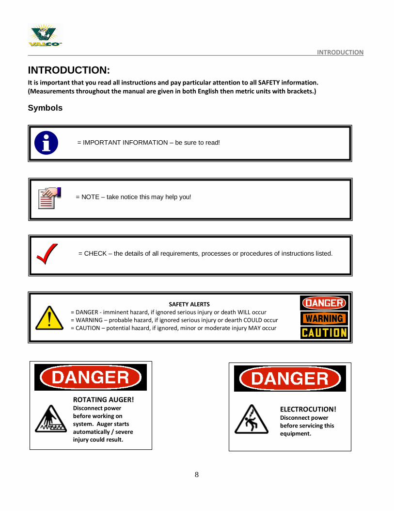
INTRODUCTION: It is important that you read all instructions and pay particular attention to all SAFETY information. (Measurements throughout the manual are given in both English then metric units with brackets.)
Symbols
= IMPORTANT INFORMATION – be sure to read!
SAFETY ALERTS = DANGER - imminent hazard, if ignored serious injury or death WILL occur = WARNING – probable hazard, if ignored serious injury or dearth COULD occur = CAUTION – potential hazard, if ignored, minor or moderate injury MAY occur
= NOTE – take notice this may help you!
= CHECK – the details of all requirements, processes or procedures of instructions listed.
ROTATING AUGER! Disconnect power before working on system. Auger starts automatically / severe injury could result.
ELECTROCUTION! Disconnect power before servicing this equipment.
9
INTRODUCTION – OVERVIEW
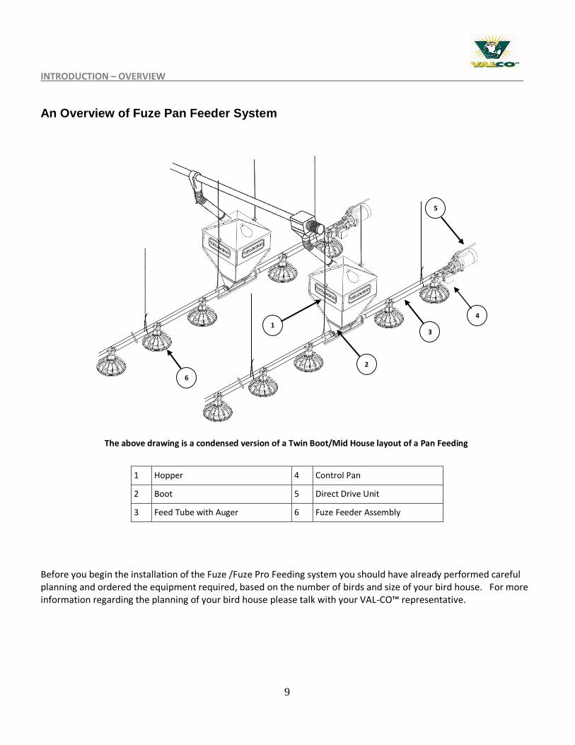
An Overview of Fuze Pan Feeder System
Before you begin the installation of the Fuze /Fuze Pro Feeding system you should have already performed careful planning and ordered the equipment required, based on the number of birds and size of your bird house. For more information regarding the planning of your bird house please talk with your VAL-CO™ representative.
1 Hopper 4 Control Pan
2 Boot 5 Direct Drive Unit
3 Feed Tube with Auger 6 Fuze Feeder Assembly
The above drawing is a condensed version of a Twin Boot/Mid House layout of a Pan Feeding System
1
2
3
4
5
6
10
INTRODUCTION – FEATURES
Feed Pan Features
VAL-CO™ Fuze and FuzePro pan feeders are ideal for broilers, turkey pullets, layers, or other poultry. Designed for:
Saving production costs Enlarged feed windows will flood the pans more evenly to provide the best start from day one. Deep center feed “V” bottom of the pan promotes feed savings. Anti-rake fins on the feed tower will prevent billing of feed to reduce waste. Grill and pan form a feed saving lip to promote additional feed savings. Pan assembly made of engineered polymers that resist harboring bacteria to promote bird health.
Easy Installation and convenience Removable top allows for easy pan assembly and installation Easy and positive feed adjustment can be made from the outside. Fuze Pro pan offers ergonomically designed multi-spoke grills. Easier entrance and exit for the chicks. Easy to clean.
Versatile and Interchangeable components Fuze Pro pan allows you to “build your own feeder”. Fuze Pro pan offer choices in pan depth and diameter.
Durability Added material thickness in critical scratch (wear) area. All parts are fully UV stabilized to promote longer life.
11
PART 1 – WINCH SYSTEM INSTALLATION – SYSTEM LAYOUT OVERVIEW
PART 1 – WINCH SYSTEM INSTALLATION
General Information
Please read all the instructions before installing the VAL-CO™ Fuze and Fuze Pro System. This manual will provide information on installing the VALCO™ Fuze and Fuze Pro feeders, Winch system, hopper, auger/feed line and the anti-roost system. The system is designed in a straight line for using an auger with 9’ through 12’ ribbed, or smooth tubes to deliver feed to the feed pans and a choice of hand or electric winches. This system can be used to feed broiler and commercial layers on a non-restricted feed schedule.
System Layout – Overviews
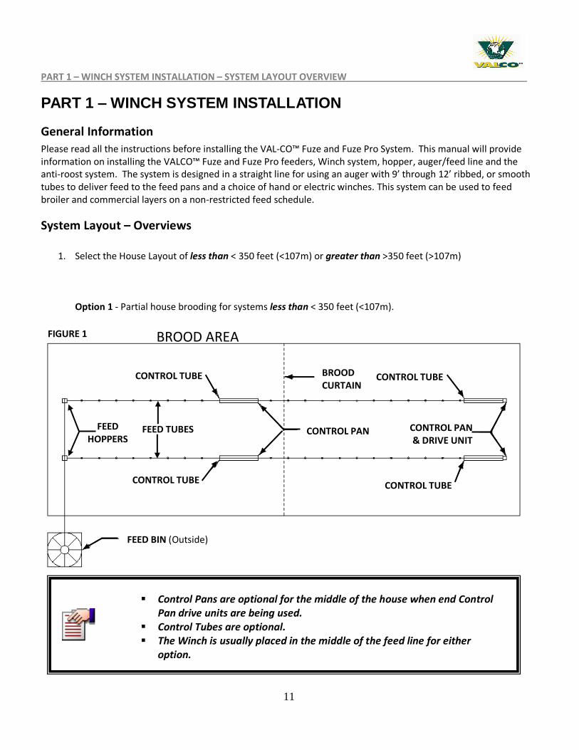
1. Select the House Layout of less than < 350 feet (<107m) or greater than >350 feet (>107m)
Option 1 - Partial house brooding for systems less than < 350 feet (<107m).
FIGURE 1 BROOD AREA
FEED TUBES
BROOD CURTAIN
CONTROL TUBE
CONTROL PAN CONTROL PAN & DRIVE UNIT
CONTROL TUBE CONTROL TUBE
CONTROL TUBE
FEED HOPPERS
FEED BIN (Outside)
Control Pans are optional for the middle of the house when end Control Pan drive units are being used.
Control Tubes are optional. The Winch is usually placed in the middle of the feed line for either
option.
12
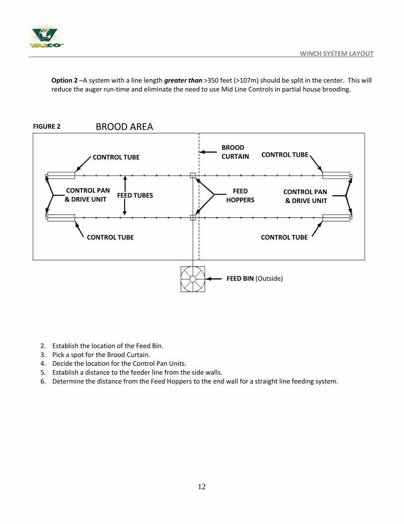
WINCH SYSTEM LAYOUT Option 2 –A system with a line length greater than >350 feet (>107m) should be split in the center. This will reduce the auger run-time and eliminate the need to use Mid Line Controls in partial house brooding.
2. Establish the location of the Feed Bin. 3. Pick a spot for the Brood Curtain. 4. Decide the location for the Control Pan Units. 5. Establish a distance to the feeder line from the side walls. 6. Determine the distance from the Feed Hoppers to the end wall for a straight line feeding system.
FIGURE 2
CONTROL TUBE
CONTROL PAN & DRIVE UNIT
CONTROL PAN & DRIVE UNIT
CONTROL TUBE CONTROL TUBE
CONTROL TUBE
FEED HOPPERS
FEED BIN (Outside)
FEED TUBES
BROOD CURTAIN
BROOD AREA
13
WINCH SYSTEM / SUSPENSION
Winch System / Suspension
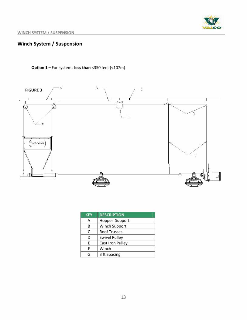
Option 1 – For systems less than <350 feet (<107m)
KEY DESCRIPTION
A Hopper Support
B Winch Support
C Roof Trusses
D Swivel Pulley
E Cast Iron Pulley
F Winch
G 3 ft Spacing
FIGURE 3
14
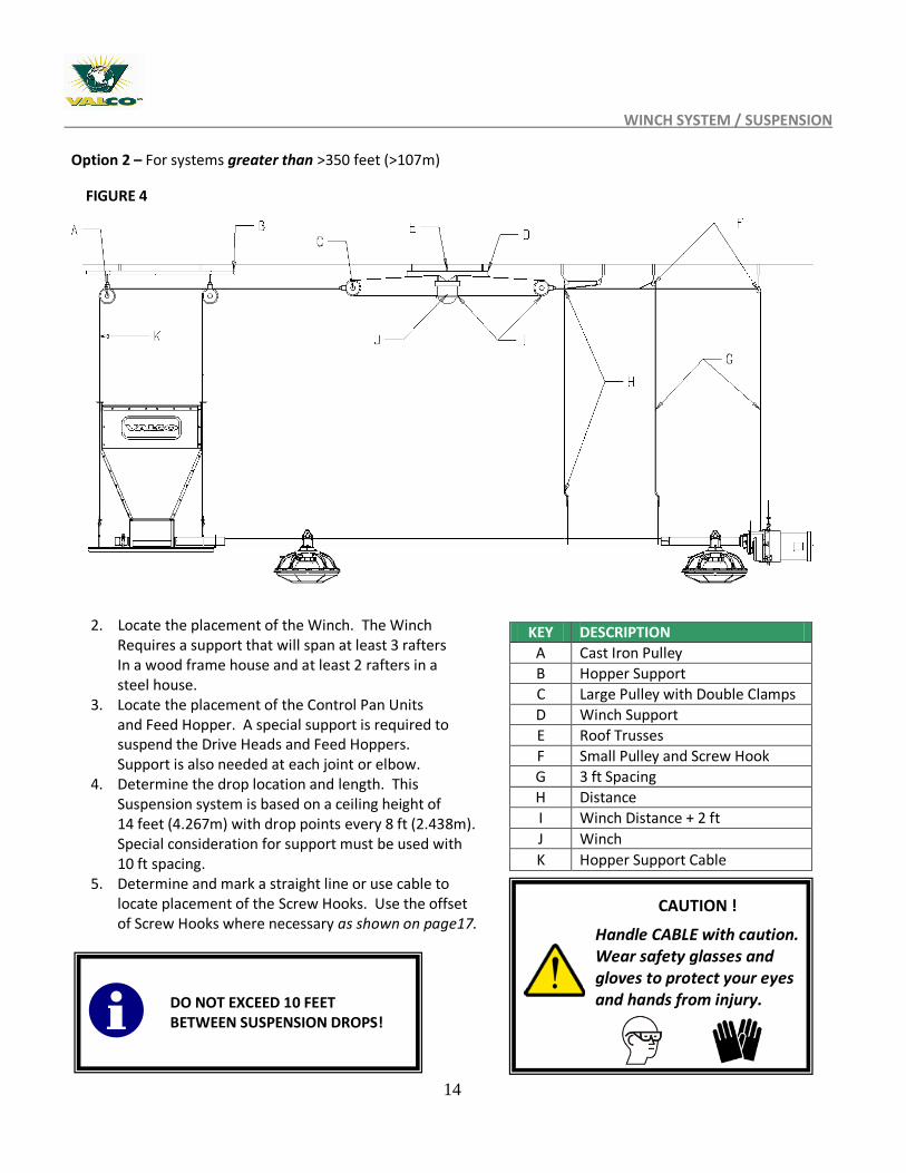
WINCH SYSTEM / SUSPENSION Option 2 – For systems greater than >350 feet (>107m)
2. Locate the placement of the Winch. The Winch Requires a support that will span at least 3 rafters In a wood frame house and at least 2 rafters in a steel house.
3. Locate the placement of the Control Pan Units and Feed Hopper. A special support is required to suspend the Drive Heads and Feed Hoppers. Support is also needed at each joint or elbow.
4. Determine the drop location and length. This Suspension system is based on a ceiling height of 14 feet (4.267m) with drop points every 8 ft (2.438m). Special consideration for support must be used with 10 ft spacing.
5. Determine and mark a straight line or use cable to locate placement of the Screw Hooks. Use the offset of Screw Hooks where necessary as shown on page17.
KEY DESCRIPTION
A Cast Iron Pulley
B Hopper Support
C Large Pulley with Double Clamps
D Winch Support
E Roof Trusses
F Small Pulley and Screw Hook
G 3 ft Spacing
H Distance
I Winch Distance + 2 ft
J Winch
K Hopper Support Cable
DO NOT EXCEED 10 FEET BETWEEN SUSPENSION DROPS!
FIGURE 4
CAUTION !
Handle CABLE with caution. Wear safety glasses and gloves to protect your eyes and hands from injury.
15
WINCH INSTALLATION
Winch Installation
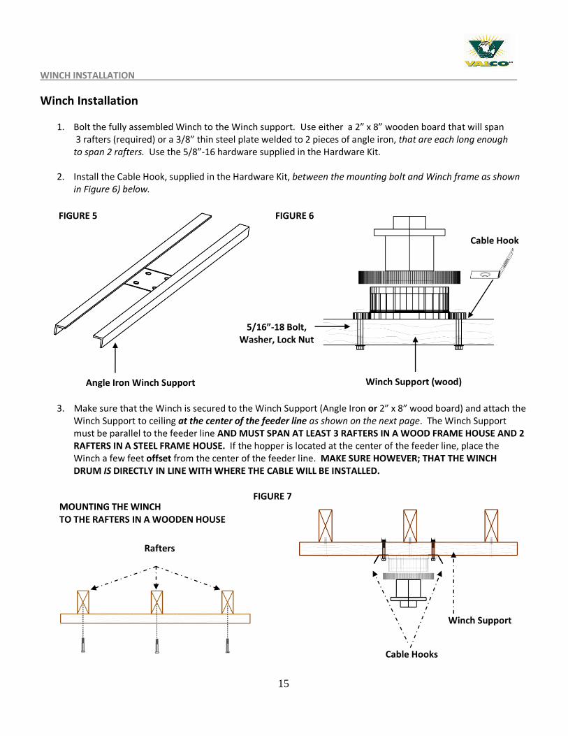
1. Bolt the fully assembled Winch to the Winch support. Use either a 2” x 8” wooden board that will span 3 rafters (required) or a 3/8” thin steel plate welded to 2 pieces of angle iron, that are each long enough to span 2 rafters. Use the 5/8”-16 hardware supplied in the Hardware Kit.
2. Install the Cable Hook, supplied in the Hardware Kit, between the mounting bolt and Winch frame as shown in Figure 6) below.
3. Make sure that the Winch is secured to the Winch Support (Angle Iron or 2” x 8” wood board) and attach the Winch Support to ceiling at the center of the feeder line as shown on the next page. The Winch Support must be parallel to the feeder line AND MUST SPAN AT LEAST 3 RAFTERS IN A WOOD FRAME HOUSE AND 2 RAFTERS IN A STEEL FRAME HOUSE. If the hopper is located at the center of the feeder line, place the Winch a few feet offset from the center of the feeder line. MAKE SURE HOWEVER; THAT THE WINCH DRUM IS DIRECTLY IN LINE WITH WHERE THE CABLE WILL BE INSTALLED.
Angle Iron Winch Support
MOUNTING THE WINCH TO THE RAFTERS IN A WOODEN HOUSE
Cable Hook
Winch Support (wood)
5/16”-18 Bolt, Washer, Lock Nut
FIGURE 5
FIGURE 7
FIGURE 6
Rafters
Winch Support
Cable Hooks
16
INSTALLING THE WINCH CABLE
Installing the Winch Cable
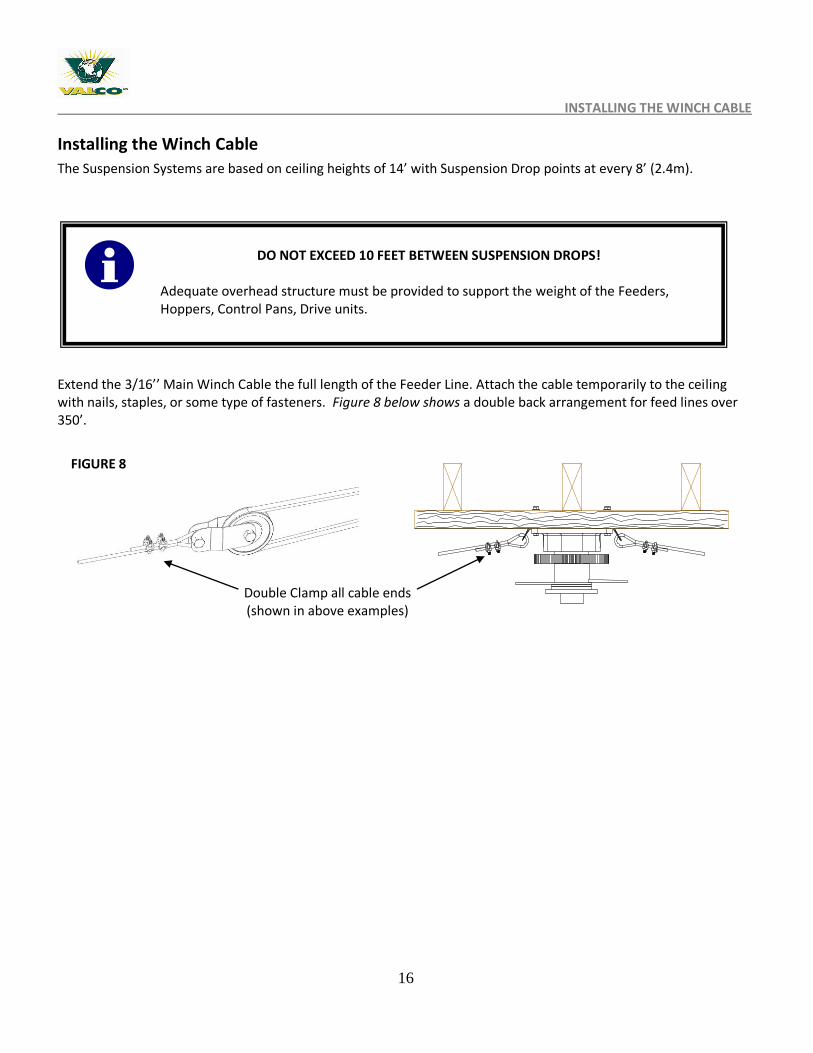
The Suspension Systems are based on ceiling heights of 14’ with Suspension Drop points at every 8’ (2.4m).
Extend the 3/16’’ Main Winch Cable the full length of the Feeder Line. Attach the cable temporarily to the ceiling with nails, staples, or some type of fasteners. Figure 8 below shows a double back arrangement for feed lines over 350’.
DO NOT EXCEED 10 FEET BETWEEN SUSPENSION DROPS!
Adequate overhead structure must be provided to support the weight of the Feeders, Hoppers, Control Pans, Drive units.
FIGURE 8
Double Clamp all cable ends (shown in above examples)
17
SCREW HOOK INSTALLATION
Screw Hook Installation
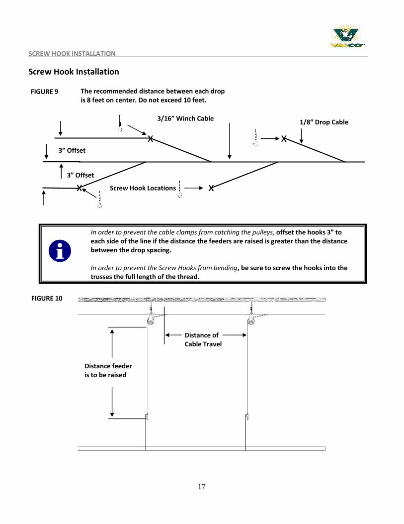
The recommended distance between each drop is 8 feet on center. Do not exceed 10 feet.
FIGURE 9
3/16” Winch Cable
3” Offset
Screw Hook Locations x
x x
x
Distance feeder is to be raised
Distance of Cable Travel
In order to prevent the cable clamps from catching the pulleys, offset the hooks 3” to each side of the line if the distance the feeders are raised is greater than the distance between the drop spacing. In order to prevent the Screw Hooks from bending, be sure to screw the hooks into the trusses the full length of the thread.
1/8” Drop Cable
3” Offset
FIGURE 10
18
SCREW HOOK & DROP INSTALLATION
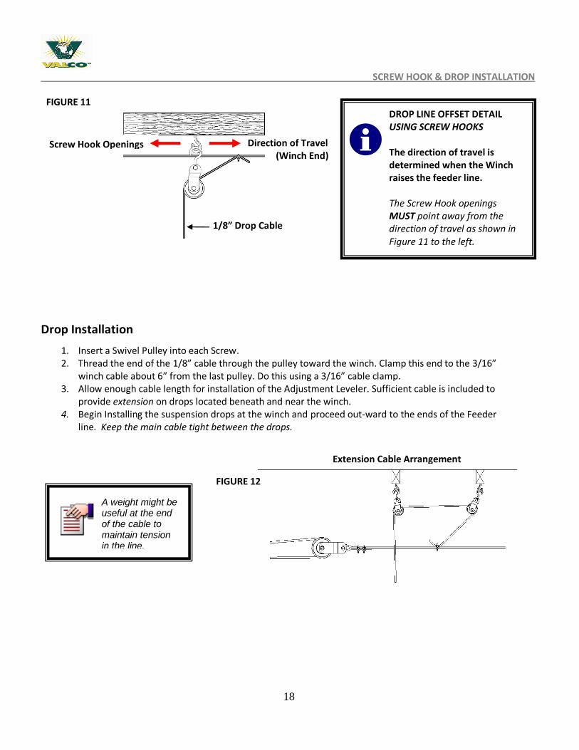
Drop Installation
1. Insert a Swivel Pulley into each Screw. 2. Thread the end of the 1/8” cable through the pulley toward the winch. Clamp this end to the 3/16”
winch cable about 6” from the last pulley. Do this using a 3/16” cable clamp. 3. Allow enough cable length for installation of the Adjustment Leveler. Sufficient cable is included to
provide extension on drops located beneath and near the winch. 4. Begin Installing the suspension drops at the winch and proceed out-ward to the ends of the Feeder
line. Keep the main cable tight between the drops.
A weight might be useful at the end of the cable to maintain tension in the line.
FIGURE 11
FIGURE 12
Screw Hook Openings Direction of Travel (Winch End)
DROP LINE OFFSET DETAIL USING SCREW HOOKS The direction of travel is determined when the Winch raises the feeder line. The Screw Hook openings MUST point away from the direction of travel as shown in Figure 11 to the left.
1/8” Drop Cable
Extension Cable Arrangement
19
PART 2 - FUZE FEEDER- FEEDER ASSEMBLY OVERVIEW
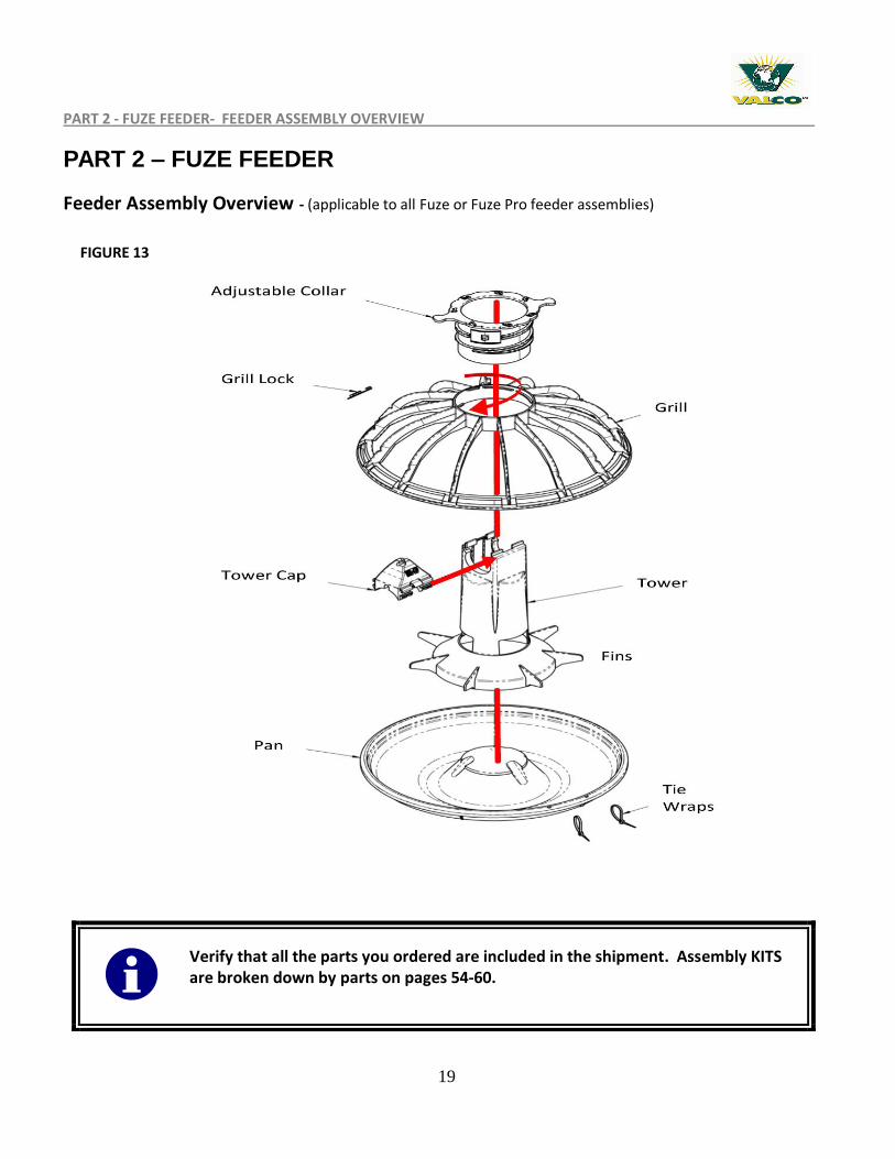
PART 2 – FUZE FEEDER
Feeder Assembly Overview - (applicable to all Fuze or Fuze Pro feeder assemblies)
(990002-2)
Verify that all the parts you ordered are included in the shipment. Assembly KITS are broken down by parts on pages 54-60.
FIGURE 13
20
DETAILED FEEDER ASSEMBLY - (All Fuze Feeders)
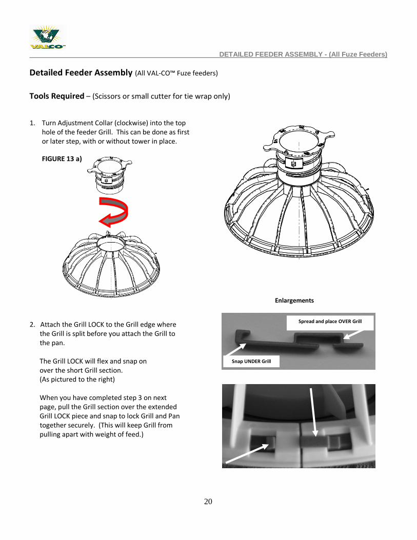
Detailed Feeder Assembly (All VAL-CO™ Fuze feeders)
Tools Required – (Scissors or small cutter for tie wrap only)
1. Turn Adjustment Collar (clockwise) into the top hole of the feeder Grill. This can be done as first or later step, with or without tower in place.
2. Attach the Grill LOCK to the Grill edge where the Grill is split before you attach the Grill to the pan. The Grill LOCK will flex and snap on over the short Grill section. (As pictured to the right) When you have completed step 3 on next page, pull the Grill section over the extended Grill LOCK piece and snap to lock Grill and Pan together securely. (This will keep Grill from pulling apart with weight of feed.)
Spread and place OVER Grill
Snap UNDER Grill
Enlargements
FIGURE 13 a)
21
DETAILED FEEDER ASSEMBLY CONTINUED - (All Feeders)
Detailed Feeder Assembly (All feeders) - continued
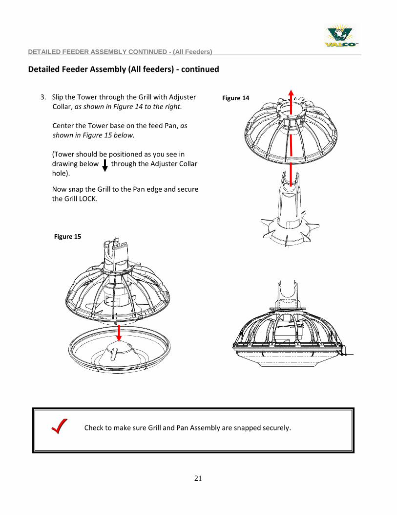
3. Slip the Tower through the Grill with Adjuster Collar, as shown in Figure 14 to the right. Center the Tower base on the feed Pan, as shown in Figure 15 below.
(Tower should be positioned as you see in drawing below through the Adjuster Collar hole).
Now snap the Grill to the Pan edge and secure the Grill LOCK.
Check to make sure Grill and Pan Assembly are snapped securely.
Figure 14
Figure 15
22
PAN FEEDER ASSEMBLY (All Feeders)
Detailed Feeder Assembly (All feeders) - continued
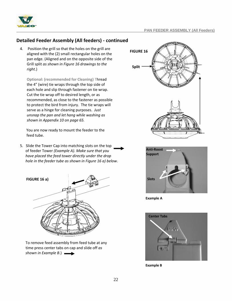
5. Slide the Tower Cap into matching slots on the top of feeder Tower (Example A). Make sure that you have placed the feed tower directly under the drop hole in the feeder tube as shown in Figure 16 a) below.
TO ASSIST OR REMOVE TOWER CAP To remove feed assembly from feed tube at any time press center tabs on cap and slide off as shown in Example B.)
4. Position the grill so that the holes on the grill are aligned with the (2) small rectangular holes on the pan edge. (Aligned and on the opposite side of the Grill split as shown in Figure 16 drawings to the right.) Optional: (recommended for Cleaning) Thread the 4” (wire) tie wraps through the top side of each hole and slip through fastener on tie wrap. Cut the tie wrap off to desired length, or as recommended, as close to the fastener as possible to protect the bird from injury. The tie wraps will serve as a hinge for cleaning purposes. Just unsnap the pan and let hang while washing as shown in Appendix 10 on page 65.
You are now ready to mount the feeder to the feed tube.
Example A
Example B
FIGURE 16 a)
Anti-Roost Support
Slots
Split
Center Tabs
FIGURE 16
23
DETAILED FEEDER ASSEMBLY CONTINUED - (All Feeders)
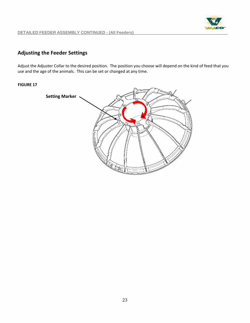
Adjusting the Feeder Settings
Adjust the Adjuster Collar to the desired position. The position you choose will depend on the kind of feed that you use and the age of the animals. This can be set or changed at any time.
Setting Marker
FIGURE 17
24
FEED LINE ASSEMBLY & SUSPENSION
PART 3 – FEED LINE ASSEMBLY & SUSPENSION
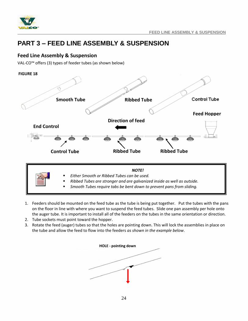
Feed Line Assembly & Suspension
VAL-CO™ offers (3) types of feeder tubes (as shown below)
1. Feeders should be mounted on the feed tube as the tube is being put together. Put the tubes with the pans
on the floor in line with where you want to suspend the feed tubes. Slide one pan assembly per hole onto the auger tube. It is important to install all of the feeders on the tubes in the same orientation or direction.
2. Tube sockets must point toward the hopper. 3. Rotate the feed (auger) tubes so that the holes are pointing down. This will lock the assemblies in place on
the tube and allow the feed to flow into the feeders as shown in the example below.
HOLE - pointing down
NOTE! Either Smooth or Ribbed Tubes can be used. Ribbed Tubes are stronger and are galvanized inside as well as outside. Smooth Tubes require tabs be bent down to prevent pans from sliding.
FIGURE 18
Ribbed Tube
Ribbed Tube Ribbed Tube
Smooth Tube
Control Tube
End Control Direction of feed flow
Feed Hopper
25
FEED LINE ASSEMBLY & SUSPENSION
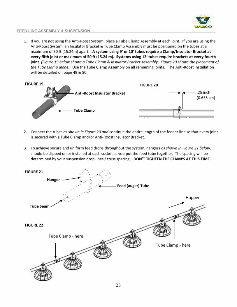
1. If you are not using the Anti-Roost System, place a Tube Clamp Assembly at each joint. If you are using the
Anti-Roost System, an Insulator Bracket & Tube Clamp Assembly must be positioned on the tubes at a maximum of 50 ft (15.24m) apart. A system using 9’ or 10’ tubes require a Clamp/Insulator Bracket at every fifth joint or maximum of 50 ft (15.24 m). Systems using 12’ tubes require brackets at every fourth joint. (Figure 19 below shows a Tube Clamp & Insulator Bracket Assembly. Figure 20 shows the placement of the Tube Clamp alone. Use the Tube Clamp Assembly on all remaining joints. The Anti-Roost installation will be detailed on page 49 & 50.
2. Connect the tubes as shown in Figure 20 and continue the entire length of the feeder line so that every joint
is secured with a Tube Clamp and/or Anti-Roost Insulator Bracket.
3. To achieve secure and uniform feed drops throughout the system, hangers as shown in Figure 21 below,
should be slipped on or installed at each socket as you put the feed tube together. The spacing will be
determined by your suspension drop lines / truss spacing. DON’T TIGHTEN THE CLAMPS AT THIS TIME.
Tube Clamp - here
Hopper
Tube Clamp - here
FIGURE 21
FIGURE 22
FIGURE 20
.25 inch (0.635 cm)
Tube Clamp
Anti-Roost Insulator Bracket
FIGURE 19
Hanger
Feed (auger) Tube
Tube Seam
26
FEED LINE ASSEMBLY & SUSPENSION
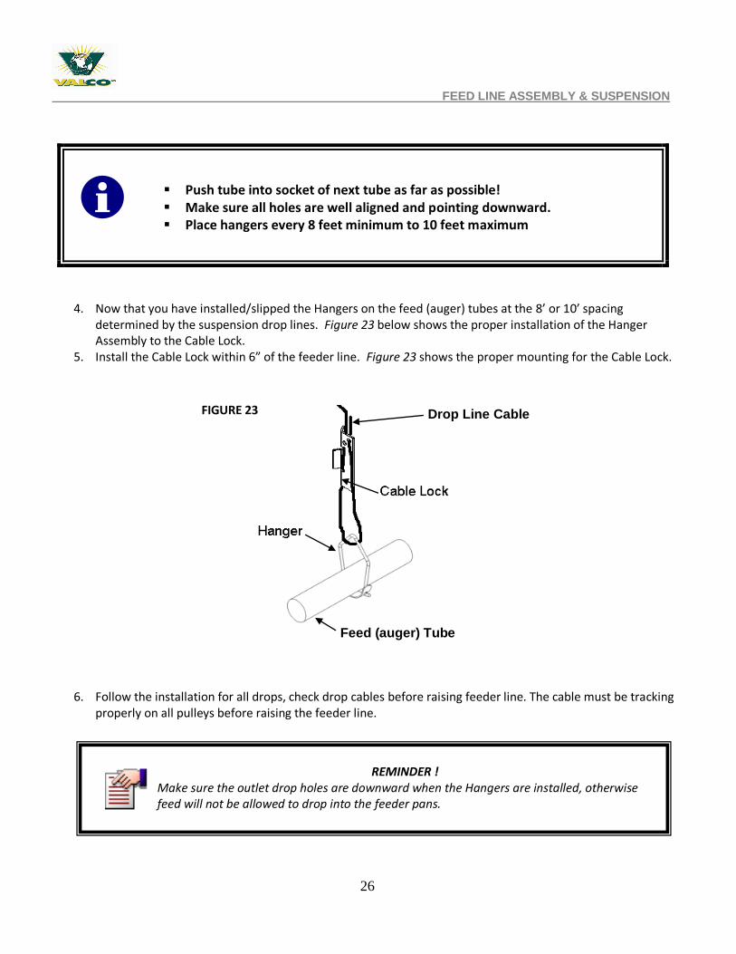
4. Now that you have installed/slipped the Hangers on the feed (auger) tubes at the 8’ or 10’ spacing determined by the suspension drop lines. Figure 23 below shows the proper installation of the Hanger Assembly to the Cable Lock.
5. Install the Cable Lock within 6” of the feeder line. Figure 23 shows the proper mounting for the Cable Lock.
6. Follow the installation for all drops, check drop cables before raising feeder line. The cable must be tracking properly on all pulleys before raising the feeder line.
Push tube into socket of next tube as far as possible!
Make sure all holes are well aligned and pointing downward. Place hangers every 8 feet minimum to 10 feet maximum
FIGURE 23
REMINDER ! Make sure the outlet drop holes are downward when the Hangers are installed, otherwise feed will not be allowed to drop into the feeder pans.
Drop Line Cable
Feed (auger) Tube
27
FEED LINE ASSEMBLY & SUSPENSION
7. Raise the feeder line to a convenient working height. 8. Measure from the floor or ceiling to the auger tubes to level the system. This is to be done while the line is
suspended. 9. Before tightening the clamp:
Make sure each tube is level Ensure that the end of each tube is fully inserted into the belled end of the next tube. Make sure the tube clamps are located as shown in Figures 19 & 20 on page 25.
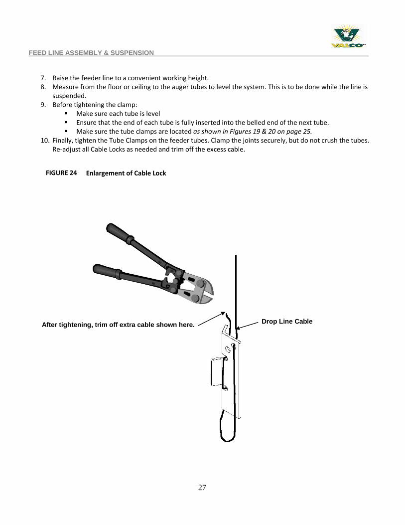
10. Finally, tighten the Tube Clamps on the feeder tubes. Clamp the joints securely, but do not crush the tubes. Re-adjust all Cable Locks as needed and trim off the excess cable.
Enlargement of Cable Lock
After tightening, trim off extra cable shown here.
FIGURE 24
Drop Line Cable
28
PART 4 – END CONTROL PAN UNIT INSTALLATION
PART 4 – END CONTROL PAN UNIT / Motor INSTALLATION
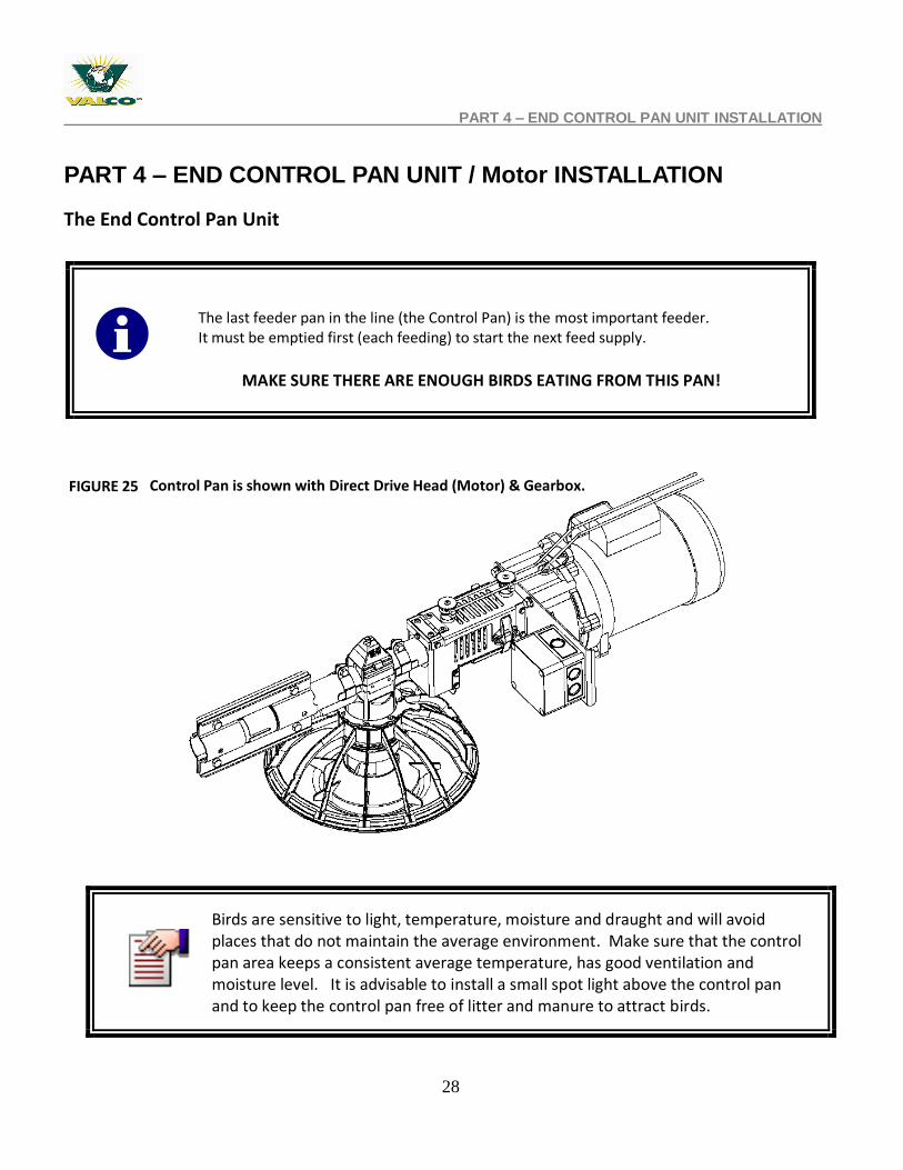
The End Control Pan Unit
The last feeder pan in the line (the Control Pan) is the most important feeder. It must be emptied first (each feeding) to start the next feed supply.
MAKE SURE THERE ARE ENOUGH BIRDS EATING FROM THIS PAN!
Birds are sensitive to light, temperature, moisture and draught and will avoid places that do not maintain the average environment. Make sure that the control pan area keeps a consistent average temperature, has good ventilation and moisture level. It is advisable to install a small spot light above the control pan and to keep the control pan free of litter and manure to attract birds.
Control Pan is shown with Direct Drive Head (Motor) & Gearbox. FIGURE 25
29
OVERVIEW OF CONTROL PAN UNIT LOCATION
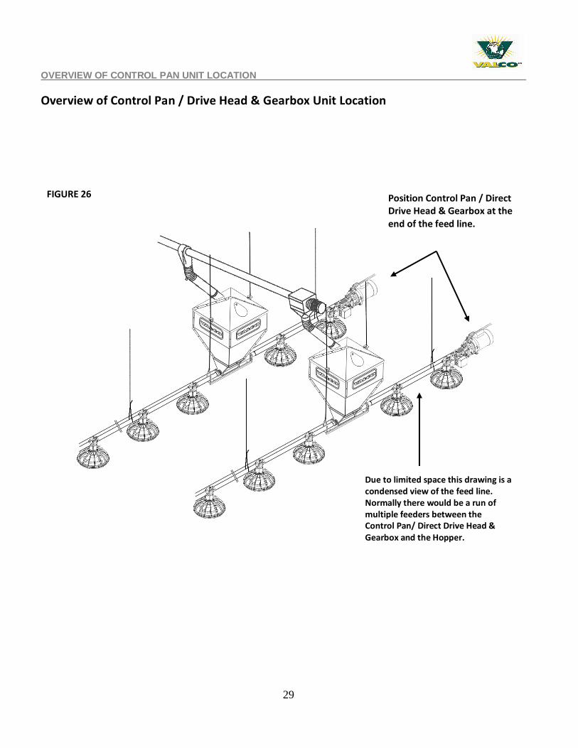
Overview of Control Pan / Drive Head & Gearbox Unit Location
Position Control Pan / Direct Drive Head & Gearbox at the end of the feed line.
FIGURE 26
Due to limited space this drawing is a condensed view of the feed line. Normally there would be a run of multiple feeders between the Control Pan/ Direct Drive Head & Gearbox and the Hopper.
30
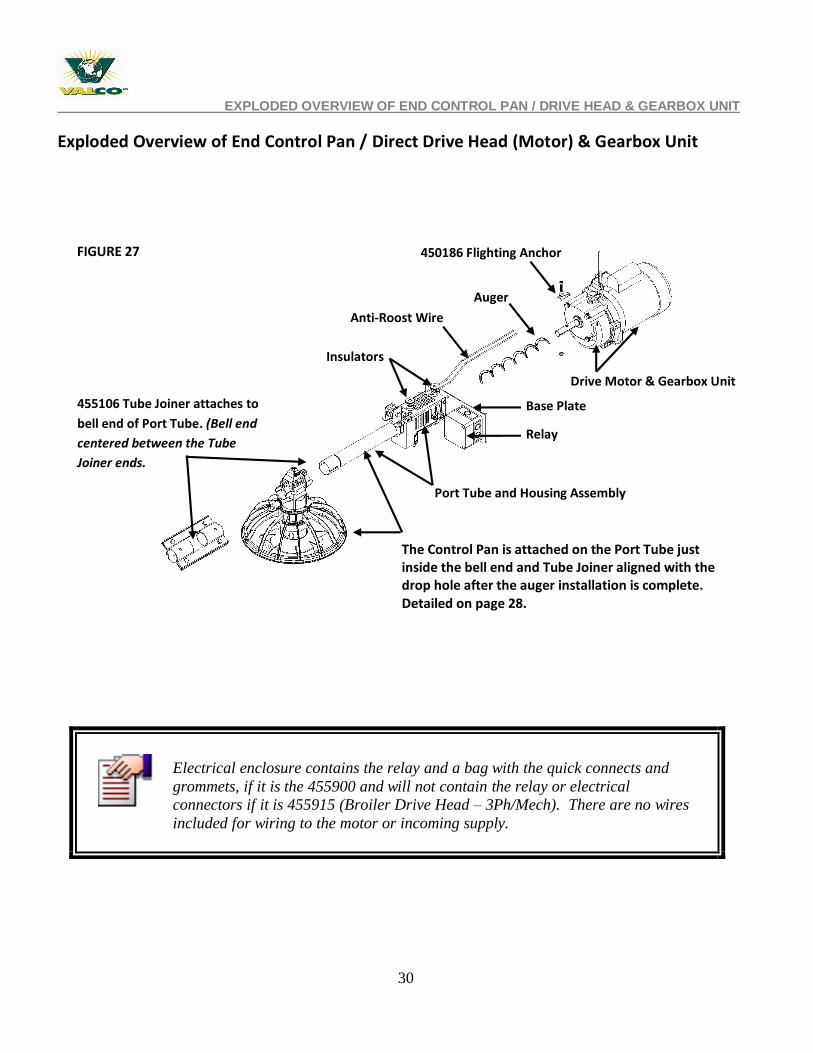
455106 Tube Joiner attaches to
bell end of Port Tube. (Bell end
centered between the Tube
Joiner ends.
Base Plate
Port Tube and Housing Assembly
Drive Motor & Gearbox Unit
Relay
Auger
Anti-Roost Wire
450186 Flighting Anchor
Insulators
Control Pan is attached on the Port Tube just beyond the
bell end and Tube joiner of the after the auger
installation is complete. (feed should flow away from the
sensor hole – detailed on page xx).
EXPLODED OVERVIEW OF END CONTROL PAN / DRIVE HEAD & GEARBOX UNIT
Exploded Overview of End Control Pan / Direct Drive Head (Motor) & Gearbox Unit
Electrical enclosure contains the relay and a bag with the quick connects and
grommets, if it is the 455900 and will not contain the relay or electrical
connectors if it is 455915 (Broiler Drive Head – 3Ph/Mech). There are no wires
included for wiring to the motor or incoming supply.
detailed on page 23).
FIGURE 27
The Control Pan is attached on the Port Tube just inside the bell end and Tube Joiner aligned with the drop hole after the auger installation is complete. Detailed on page 28.
31
DIRECT DRIVE HEAD & GEARBOX INSTALLATION
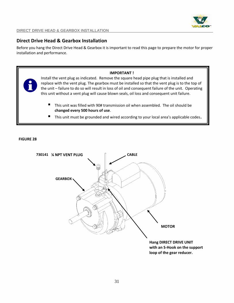
Direct Drive Head & Gearbox Installation
Before you hang the Direct Drive Head & Gearbox it is important to read this page to prepare the motor for proper installation and performance.
IMPORTANT ! Install the vent plug as indicated. Remove the square head pipe plug that is installed and replace with the vent plug. The gearbox must be installed so that the vent plug is to the top of the unit – failure to do so will result in loss of oil and consequent failure of the unit. Operating this unit without a vent plug will cause blown seals, oil loss and consequent unit failure.
This unit was filled with 90# transmission oil when assembled. The oil should be changed every 500 hours of use.
This unit must be grounded and wired according to your local area’s applicable codes.
730141 - 1/4NPT VENT PLUG
Hang Drive Head with an
S- Hook on the support
loop of the gear reducer.
CABLE
GEARBOX
DRIVE HEAD
730141 - 1/4NPT VENT PLUG
Hang Drive Head with an
S- Hook on the support
loop of the gear reducer.
CABLE
GEARBOX
DRIVE HEAD
FIGURE 28
¼ NPT VENT PLUG
MOTOR
Hang DIRECT DRIVE UNIT with an S-Hook on the support loop of the gear reducer.
32
PART 4 – DRIVE HEAD & GEARBOX INSTALLATION / DETAILED CONTROL PAN ASSEMBLY
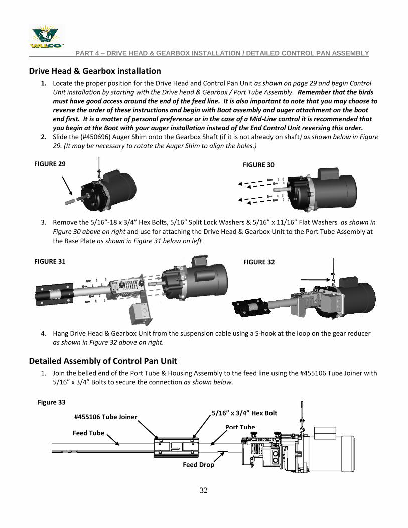
Drive Head & Gearbox installation
1. Locate the proper position for the Drive Head and Control Pan Unit as shown on page 29 and begin Control Unit installation by starting with the Drive head & Gearbox / Port Tube Assembly. Remember that the birds must have good access around the end of the feed line. It is also important to note that you may choose to reverse the order of these instructions and begin with Boot assembly and auger attachment on the boot end first. It is a matter of personal preference or in the case of a Mid-Line control it is recommended that you begin at the Boot with your auger installation instead of the End Control Unit reversing this order.
2. Slide the (#450696) Auger Shim onto the Gearbox Shaft (if it is not already on shaft) as shown below in Figure 29. (It may be necessary to rotate the Auger Shim to align the holes.)
3. Remove the 5/16”-18 x 3/4” Hex Bolts, 5/16” Split Lock Washers & 5/16” x 11/16” Flat Washers as shown in
Figure 30 above on right and use for attaching the Drive Head & Gearbox Unit to the Port Tube Assembly at
the Base Plate as shown in Figure 31 below on left
4. Hang Drive Head & Gearbox Unit from the suspension cable using a S-hook at the loop on the gear reducer
as shown in Figure 32 above on right.
Detailed Assembly of Control Pan Unit
1. Join the belled end of the Port Tube & Housing Assembly to the feed line using the #455106 Tube Joiner with 5/16” x 3/4” Bolts to secure the connection as shown below.
FIGURE 30
FIGURE 32 FIGURE 31
FIGURE 29
#455106 Tube Joiner
Feed Tube
5/16” x 3/4” Hex Bolt
Port Tube
Feed Drop
Figure 33
33
PART 4 - DETAILED ASSEMBLY OF CONTROL PAN UNIT
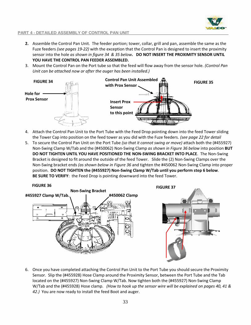
2. Assemble the Control Pan Unit. The feeder portion; tower, collar, grill and pan, assemble the same as the
Fuze feeders (see pages 19-22) with the exception that the Control Pan is designed to insert the proximity sensor into the hole as shown in figure 34 & 35 below. DO NOT INSERT THE PROXIMITY SENSOR UNTIL YOU HAVE THE CONTROL PAN FEEDER ASSEMBLED.
3. Mount the Control Pan on the Port tube so that the feed will flow away from the sensor hole. (Control Pan Unit can be attached now or after the auger has been installed.)
4. Attach the Control Pan Unit to the Port Tube with the Feed Drop pointing down into the feed Tower sliding the Tower Cap into position on the feed tower as you did with the Fuze feeders. (see page 22 for detail
5. To secure the Control Pan Unit on the Port Tube (so that it cannot swing or move) attach both the (#455927) Non-Swing Clamp W/Tab and the (#450062) Non-Swing Clamp as shown in Figure 36 below into position BUT DO NOT TIGHTEN UNTIL YOU HAVE POSITIONED THE NON-SWING BRACKET INTO PLACE. The Non-Swing Bracket is designed to fit around the outside of the feed Tower. Slide the (2) Non-Swing Clamps over the Non-Swing bracket ends (as shown below in Figure 36 and tighten the #450062 Non-Swing Clamp into proper position. DO NOT TIGHTEN the (#455927) Non-Swing Clamp W/Tab until you perform step 6 below. BE SURE TO VERIFY: the Feed Drop is pointing downward into the feed Tower.
6. Once you have completed attaching the Control Pan Unit to the Port Tube you should secure the Proximity Sensor. Slip the (#455928) Hose Clamp around the Proximity Sensor, between the Port Tube and the Tab located on the (#455927) Non-Swing Clamp W/Tab. Now tighten both the (#455927) Non-Swing Clamp W/Tab and the (#455928) Hose clamp. (How to hook up the sensor wire will be explained on pages 40, 41 & 42.) You are now ready to install the feed Boot and auger.
Hole for Prox Sensor
Non-Swing Bracket #450062 Clamp
Control Pan Unit Assembled with Prox Sensor
FIGURE 35
Insert Prox Sensor to this point
FIGURE 36
#455927 Clamp W/Tab.
FIGURE 34
FIGURE 37
34
PART 5 - FEED BOOT INSTALLATION
PART 5 - FEED BOOT INSTALLATION
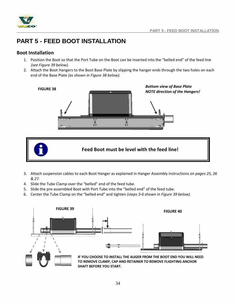
Boot Installation
1. Position the Boot so that the Port Tube on the Boot can be inserted into the “belled end” of the feed line (see Figure 39 below).
2. Attach the Boot Hangers to the Boot Base Plate by slipping the hanger ends through the two holes on each end of the Base Plate (as shown in Figure 38 below).
3. Attach suspension cables to each Boot Hanger as explained in Hanger Assembly instructions on pages 25, 26 & 27.
4. Slide the Tube Clamp over the “belled” end of the feed tube. 5. Slide the pre-assembled Boot with Port Tube into the “belled end” of the feed tube. 6. Center the Tube Clamp on the “belled end” and tighten (steps 3-6 shown in Figure 39 below).
IF YOU CHOOSE TO INSTALL THE AUGER FROM THE BOOT END YOU WILL NEED TO REMOVE CLAMP, CAP AND RETAINER TO REMOVE FLIGHTING ANCHOR SHAFT BEFORE YOU START.
Feed Boot must be level with the feed line!
FIGURE 38
FIGURE 39
Bottom view of Base Plate NOTE direction of the Hangers!
FIGURE 40
35
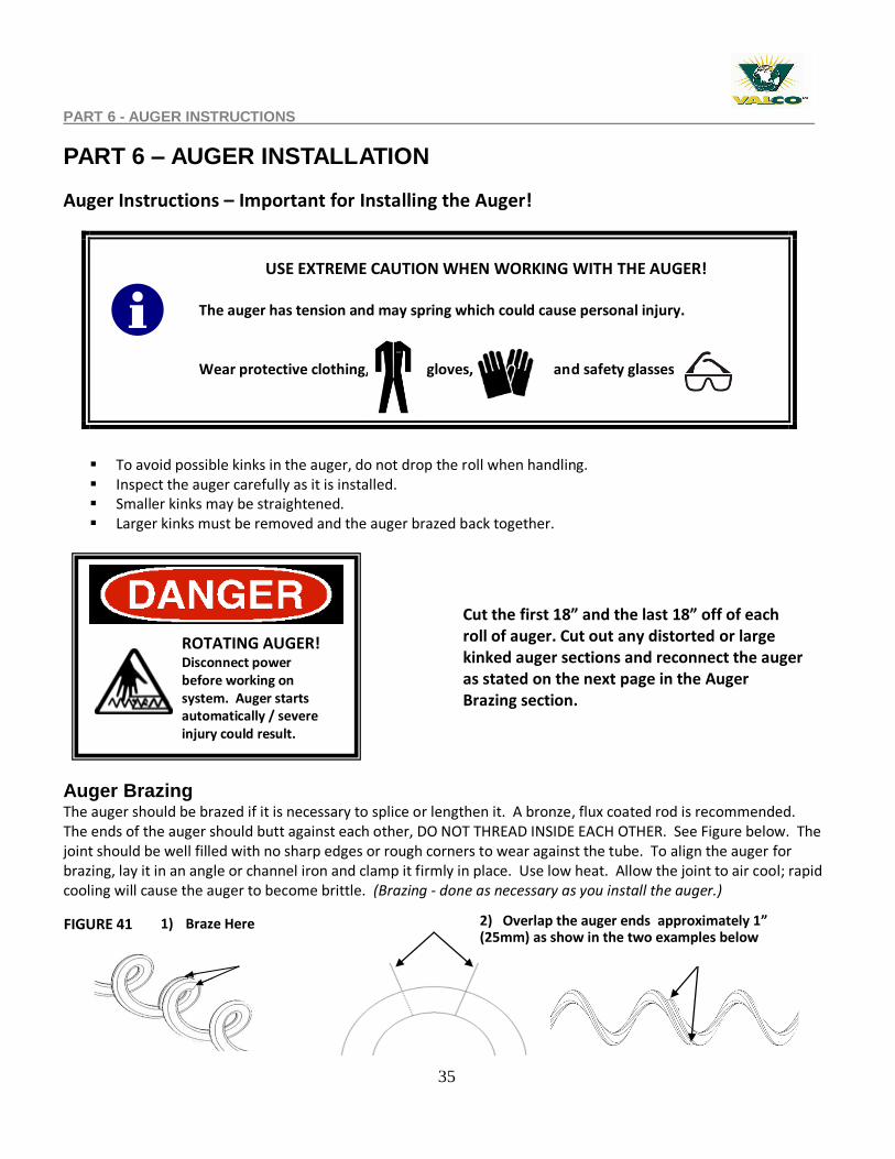
2) Overlap the auger ends approximately 1” (25mm) as show in the two examples below
1) Braze Here
PART 6 - AUGER INSTRUCTIONS
PART 6 – AUGER INSTALLATION
Auger Instructions – Important for Installing the Auger!
To avoid possible kinks in the auger, do not drop the roll when handling. Inspect the auger carefully as it is installed. Smaller kinks may be straightened. Larger kinks must be removed and the auger brazed back together.
Auger Brazing The auger should be brazed if it is necessary to splice or lengthen it. A bronze, flux coated rod is recommended. The ends of the auger should butt against each other, DO NOT THREAD INSIDE EACH OTHER. See Figure below. The joint should be well filled with no sharp edges or rough corners to wear against the tube. To align the auger for brazing, lay it in an angle or channel iron and clamp it firmly in place. Use low heat. Allow the joint to air cool; rapid cooling will cause the auger to become brittle. (Brazing - done as necessary as you install the auger.)
Cut the first 18” and the last 18” off of each roll of auger. Cut out any distorted or large kinked auger sections and reconnect the auger as stated on the next page in the Auger Brazing section.
USE EXTREME CAUTION WHEN WORKING WITH THE AUGER!
The auger has tension and may spring which could cause personal injury. Wear protective clothing, gloves, and safety glasses
ROTATING AUGER! Disconnect power before working on system. Auger starts automatically / severe injury could result.
FIGURE 41
36
AUGER INSTALLATION
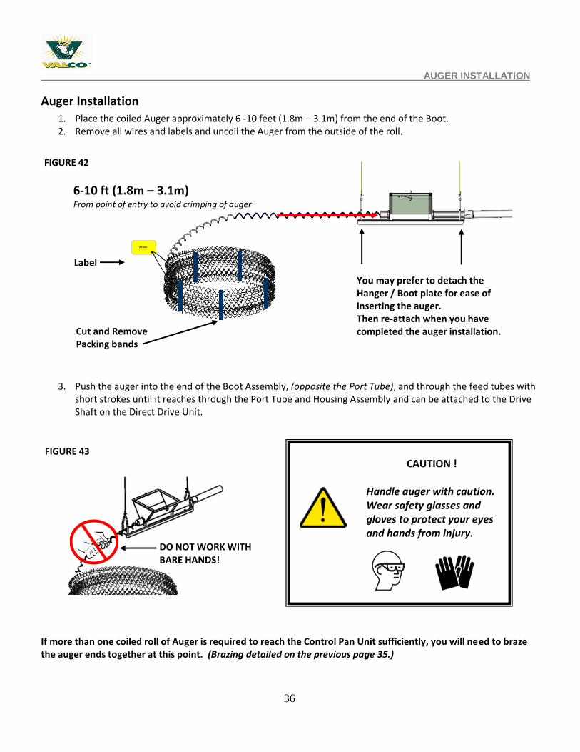
Auger Installation
1. Place the coiled Auger approximately 6 -10 feet (1.8m – 3.1m) from the end of the Boot. 2. Remove all wires and labels and uncoil the Auger from the outside of the roll.
3. Push the auger into the end of the Boot Assembly, (opposite the Port Tube), and through the feed tubes with short strokes until it reaches through the Port Tube and Housing Assembly and can be attached to the Drive Shaft on the Direct Drive Unit.
If more than one coiled roll of Auger is required to reach the Control Pan Unit sufficiently, you will need to braze the auger ends together at this point. (Brazing detailed on the previous page 35.)
Label
Cut and Remove Packing bands
CAUTION !
Handle auger with caution. Wear safety glasses and gloves to protect your eyes and hands from injury.
FIGURE 42
FIGURE 43
6-10 ft (1.8m – 3.1m) From point of entry to avoid crimping of auger
xxxxxxxxxxxxx
.
You may prefer to detach the Hanger / Boot plate for ease of inserting the auger. Then re-attach when you have completed the auger installation.
DO NOT WORK WITH BARE HANDS!
37
AUGER INSTALLATION
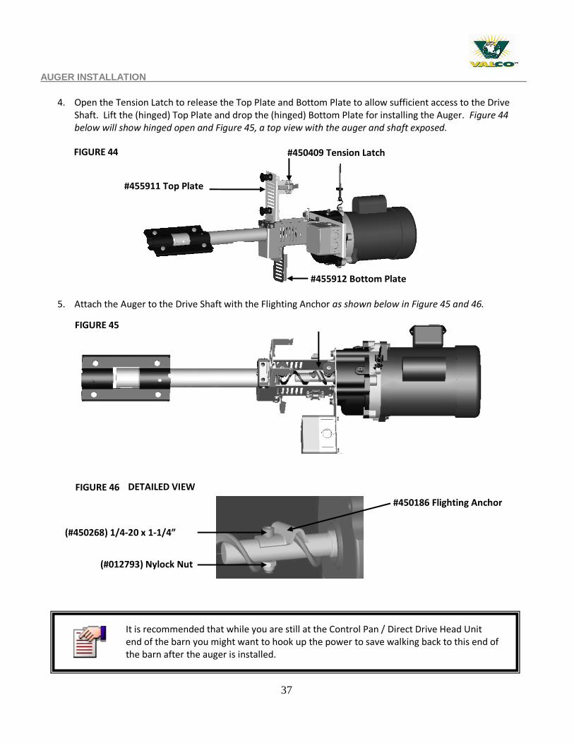
4. Open the Tension Latch to release the Top Plate and Bottom Plate to allow sufficient access to the Drive
Shaft. Lift the (hinged) Top Plate and drop the (hinged) Bottom Plate for installing the Auger. Figure 44 below will show hinged open and Figure 45, a top view with the auger and shaft exposed.
5. Attach the Auger to the Drive Shaft with the Flighting Anchor as shown below in Figure 45 and 46.
(#012793) Nylock Nut
(#450268) 1/4-20 x 1-1/4” SHCS
DETAILED VIEW FIGURE 46
#450186 Flighting Anchor
FIGURE 45
FIGURE 44
#455911 Top Plate
#450409 Tension Latch
#455912 Bottom Plate
It is recommended that while you are still at the Control Pan / Direct Drive Head Unit end of the barn you might want to hook up the power to save walking back to this end of the barn after the auger is installed.
38
PART 7 - WIRING THE END CONTROL / DRIVE HEAD & GEARBOX UNIT
PART 7 – WIRING END CONTROL / DRIVE HEAD & GEARBOX UNIT
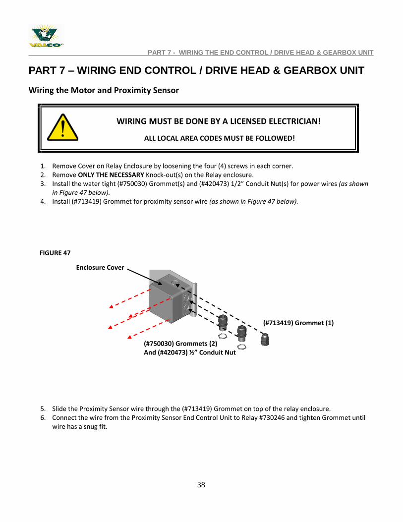
Wiring the Motor and Proximity Sensor
1. Remove Cover on Relay Enclosure by loosening the four (4) screws in each corner. 2. Remove ONLY THE NECESSARY Knock-out(s) on the Relay enclosure. 3. Install the water tight (#750030) Grommet(s) and (#420473) 1/2” Conduit Nut(s) for power wires (as shown
in Figure 47 below). 4. Install (#713419) Grommet for proximity sensor wire (as shown in Figure 47 below).
5. Slide the Proximity Sensor wire through the (#713419) Grommet on top of the relay enclosure. 6. Connect the wire from the Proximity Sensor End Control Unit to Relay #730246 and tighten Grommet until
wire has a snug fit.
(#713419) Grommet (1)
(#750030) Grommets (2) And (#420473) ½” Conduit Nut
Enclosure Cover
FIGURE 47
WIRING MUST BE DONE BY A LICENSED ELECTRICIAN!
ALL LOCAL AREA CODES MUST BE FOLLOWED!
39
WIRING THE END CONTROL / DRIVE HEAD & GEARBOX UNIT
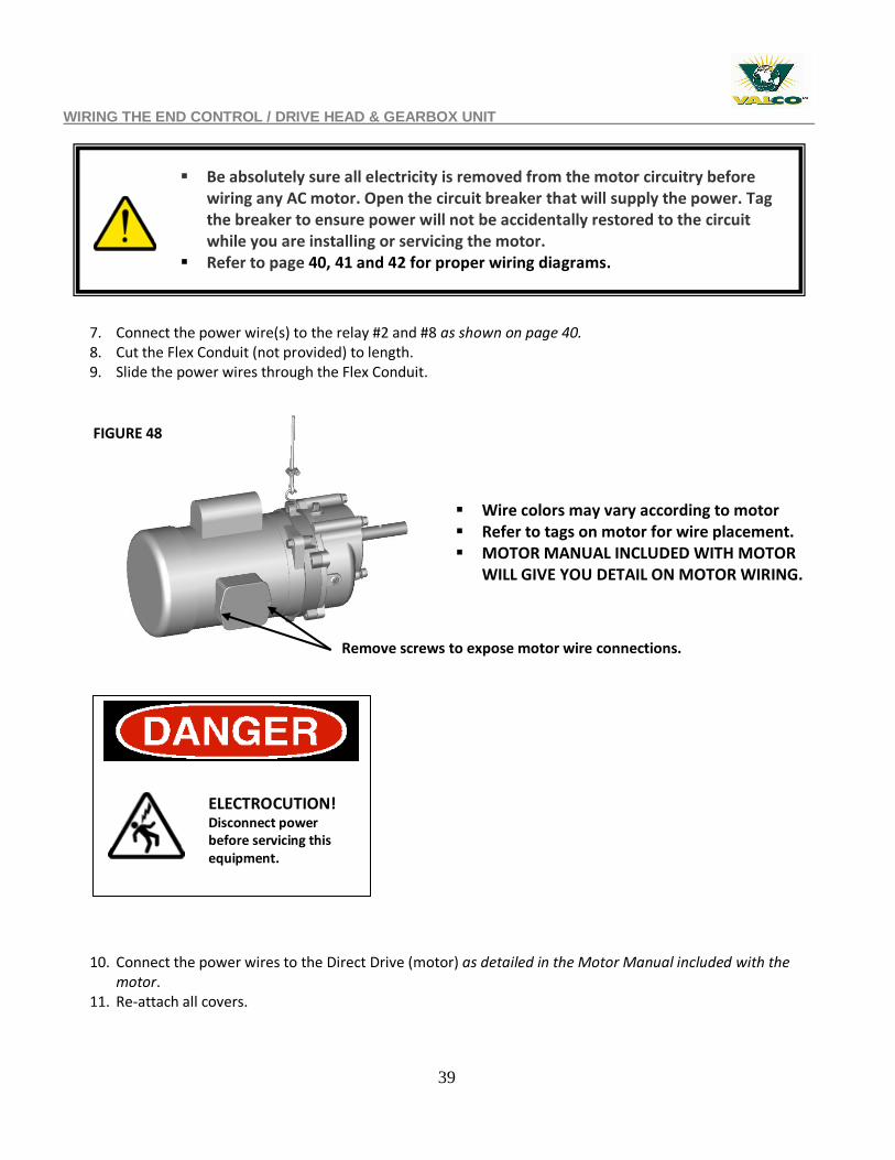
7. Connect the power wire(s) to the relay #2 and #8 as shown on page 40. 8. Cut the Flex Conduit (not provided) to length. 9. Slide the power wires through the Flex Conduit.
10. Connect the power wires to the Direct Drive (motor) as detailed in the Motor Manual included with the motor.
11. Re-attach all covers.
Wire colors may vary according to motor Refer to tags on motor for wire placement. MOTOR MANUAL INCLUDED WITH MOTOR
WILL GIVE YOU DETAIL ON MOTOR WIRING.
ELECTROCUTION! Disconnect power before servicing this equipment.
Be absolutely sure all electricity is removed from the motor circuitry before wiring any AC motor. Open the circuit breaker that will supply the power. Tag the breaker to ensure power will not be accidentally restored to the circuit while you are installing or servicing the motor.
Refer to page 40, 41 and 42 for proper wiring diagrams.
FIGURE 48
Remove screws to expose motor wire connections.
40
WIRING THE SINGLE PHASE END CONTROL
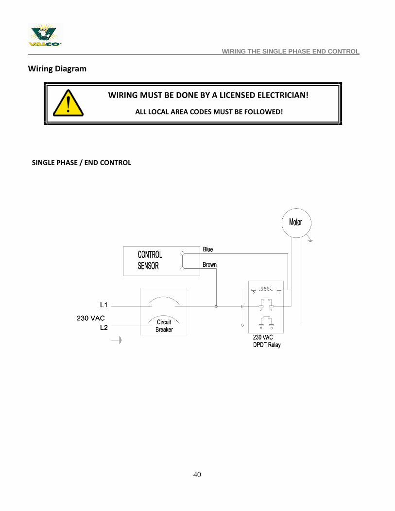
Wiring Diagram
WIRING MUST BE DONE BY A LICENSED ELECTRICIAN!
ALL LOCAL AREA CODES MUST BE FOLLOWED!
SINGLE PHASE / END CONTROL
41
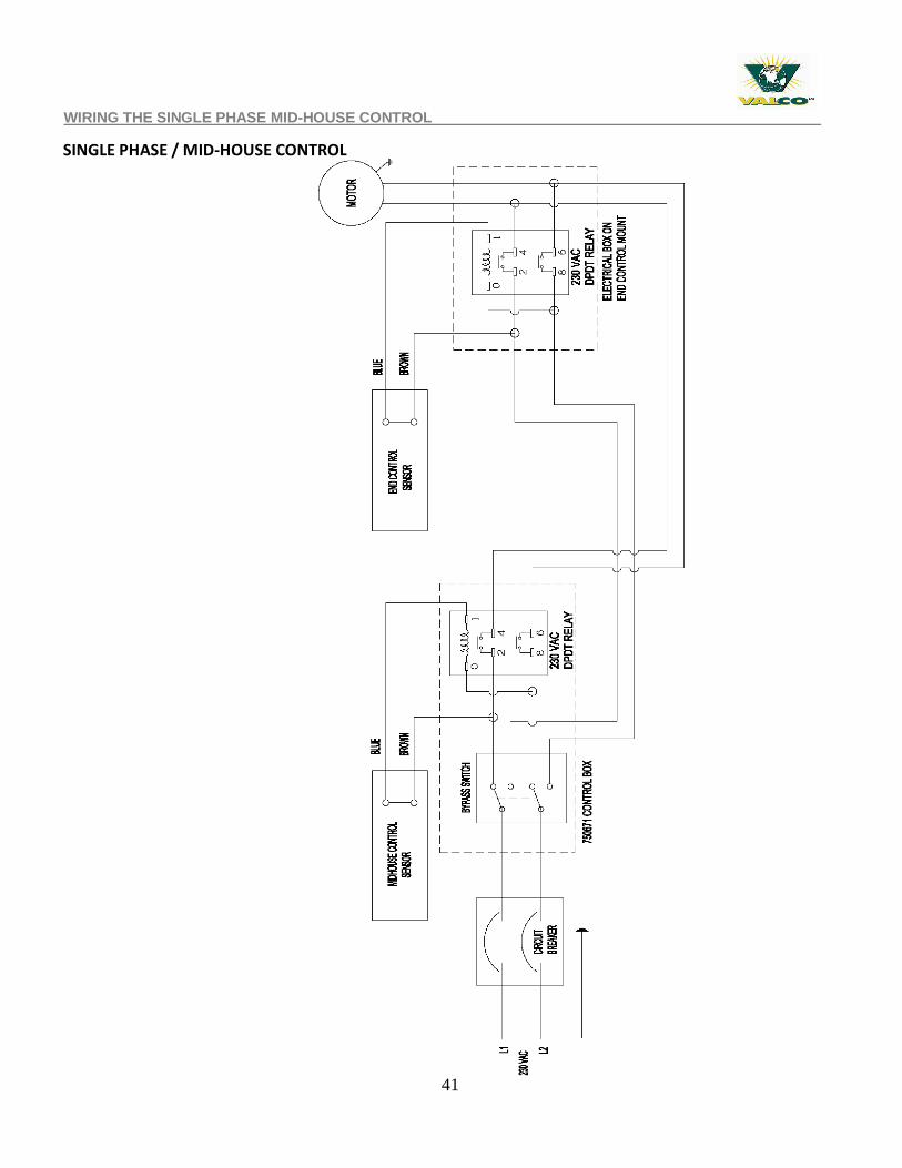
WIRING THE SINGLE PHASE MID-HOUSE CONTROL
SINGLE PHASE / MID-HOUSE CONTROL
42
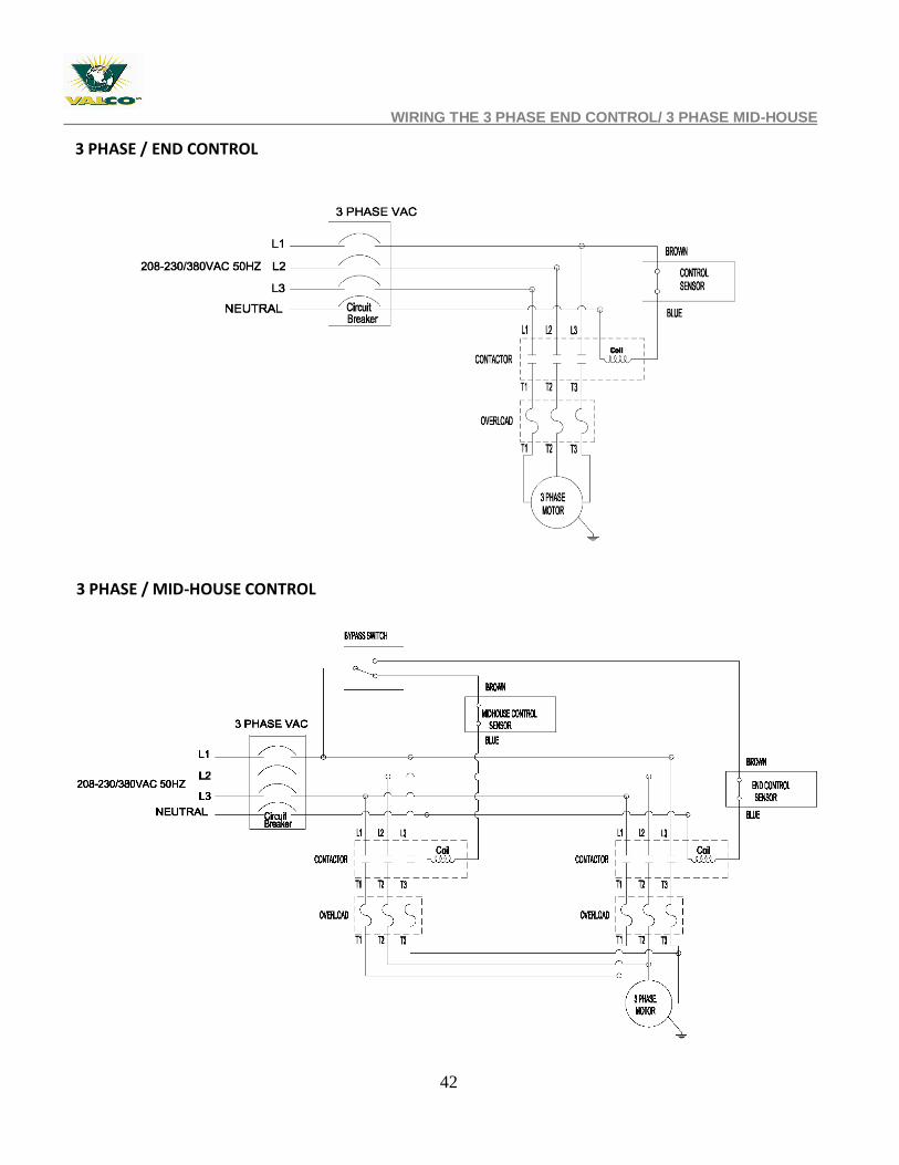
WIRING THE 3 PHASE END CONTROL/ 3 PHASE MID-HOUSE
3 PHASE / END CONTROL
3 PHASE / MID-HOUSE CONTROL
43
PART 8 - FEED BOOT - AUGER CONNECTION
PART 8 FEED BOOT – AUGER CONNECTION
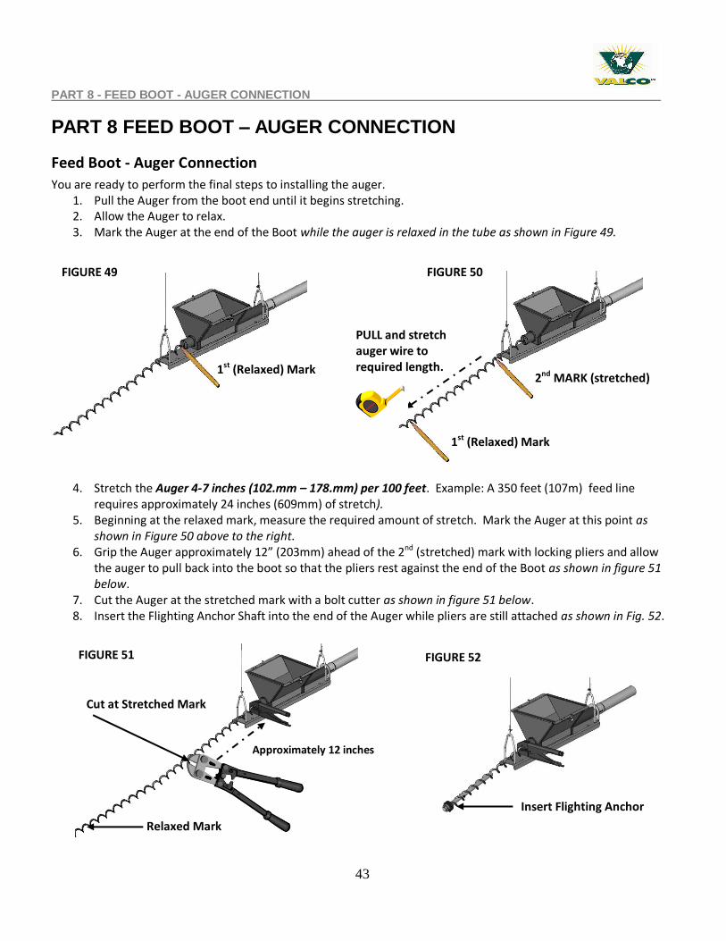
Feed Boot - Auger Connection
You are ready to perform the final steps to installing the auger. 1. Pull the Auger from the boot end until it begins stretching. 2. Allow the Auger to relax. 3. Mark the Auger at the end of the Boot while the auger is relaxed in the tube as shown in Figure 49.
4. Stretch the Auger 4-7 inches (102.mm – 178.mm) per 100 feet. Example: A 350 feet (107m) feed line requires approximately 24 inches (609mm) of stretch).
5. Beginning at the relaxed mark, measure the required amount of stretch. Mark the Auger at this point as shown in Figure 50 above to the right.
6. Grip the Auger approximately 12” (203mm) ahead of the 2nd (stretched) mark with locking pliers and allow the auger to pull back into the boot so that the pliers rest against the end of the Boot as shown in figure 51 below.
7. Cut the Auger at the stretched mark with a bolt cutter as shown in figure 51 below. 8. Insert the Flighting Anchor Shaft into the end of the Auger while pliers are still attached as shown in Fig. 52.
FIGURE 51
Figure 51
FIGURE 50 FIGURE 49
2nd MARK (stretched) 1st (Relaxed) Mark
1st (Relaxed) Mark
Cut at Stretched Mark
Relaxed Mark
PULL and stretch auger wire to required length.
Approximately 12 inches
FIGURE 52
Insert Flighting Anchor
44
PART 8 - FEED BOOT - AUGER CONNECTION
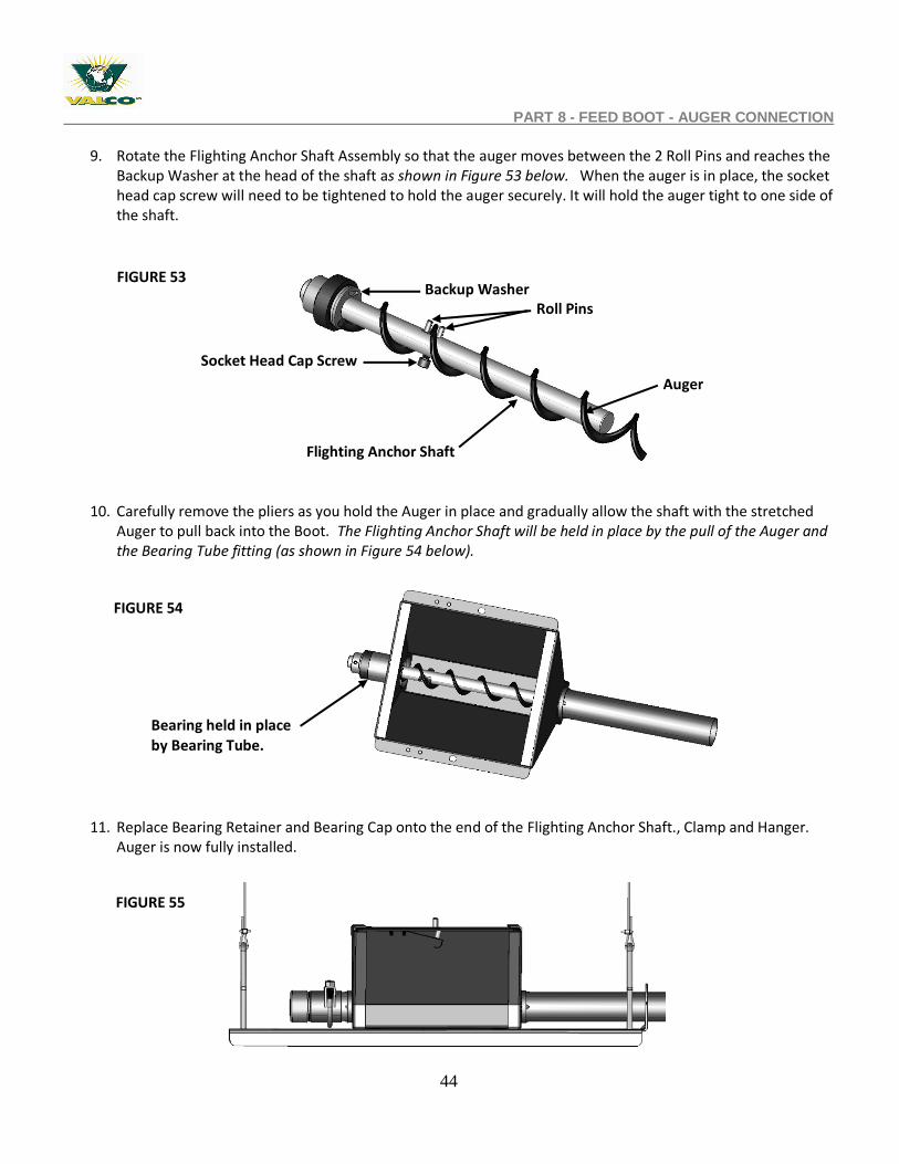
9. Rotate the Flighting Anchor Shaft Assembly so that the auger moves between the 2 Roll Pins and reaches the
Backup Washer at the head of the shaft as shown in Figure 53 below. When the auger is in place, the socket head cap screw will need to be tightened to hold the auger securely. It will hold the auger tight to one side of the shaft.
10. Carefully remove the pliers as you hold the Auger in place and gradually allow the shaft with the stretched Auger to pull back into the Boot. The Flighting Anchor Shaft will be held in place by the pull of the Auger and the Bearing Tube fitting (as shown in Figure 54 below).
11. Replace Bearing Retainer and Bearing Cap onto the end of the Flighting Anchor Shaft., Clamp and Hanger. Auger is now fully installed.
Flighting Anchor Shaft
FIGURE 53
Socket Head Cap Screw
Roll Pins Backup Washer
Auger
Bearing held in place by Bearing Tube.
FIGURE 54
FIGURE 55
45
PART 9 – HOPPER AND HOPPER LEVEL SWITCH ASSEMBLY
PART 9 – HOPPER AND HOPPER LEVEL SWITCH ASSEMBLY
Hopper Assembly / Installation
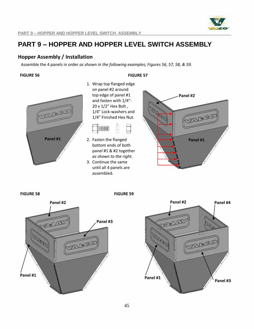
Assemble the 4 panels in order as shown in the following examples; Figures 56, 57, 58, & 59.
1. Wrap top flanged edge on panel #2 around top edge of panel #1 and fasten with 1/4”-20 x 1/2” Hex Bolt , 1/4” Lock-washers and 1/4” Finished Hex Nut.
2. Fasten the flanged
bottom ends of both panel #1 & #2 together as shown to the right.
3. Continue the same until all 4 panels are assembled.
FIGURE 56 FIGURE 57
FIGURE 58 FIGURE 59
Panel #1
Panel #2
Panel #2
Panel #1 . . .
. .
Panel #1
Panel #2 Panel #4
Panel #3
Panel #1 Panel #3
46
PART 9 – HOPPER AND HOPPER LEVEL SWITCH ASSEMBLY
FIGURE 60 FIGURE 61
FIGURE 62 FIGURE 63
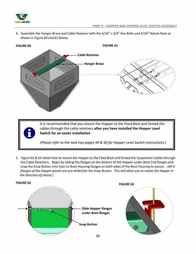
4. Assemble the Hanger Brace and Cable Retainer with the 5/16” x 3/4” Hex Bolts and 5/16” Nylock Nuts as shown in Figure 60 and 61 below.
5. Figure 62 & 63 detail how to mount the Hopper to the Feed Boot and thread the Suspension Cables through the Cable Retainers. Begin by sliding the flanges on the bottom of the Hopper under Boot End flanges and snap the Snap Button into hole on Boot Housing flanges on both sides of the Boot Housing to secure. (All 4 flanges of the Hopper panels are pre-drilled for the Snap Button. This will allow you to rotate the Hopper in the direction of choice.)
It is recommended that you mount the Hopper to the Feed Boot and thread the cables through the cable retainers after you have installed the Hopper Level Switch for an easier installation. (Please refer to the next two pages 49 & 50 for Hopper Level Switch instructions.)
Cable Retainer
Hanger Brace
Snap Button
Slide Hopper flanges under Boot flanges
47
HOPPER LEVEL SWITCH
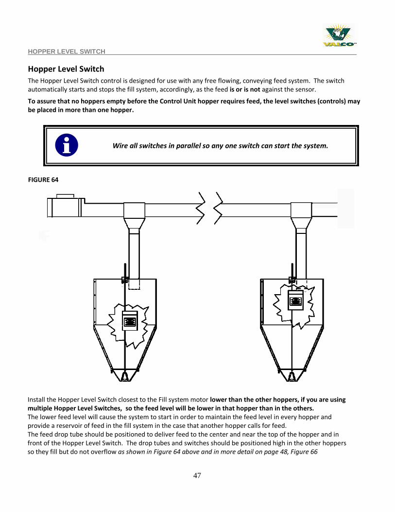
Hopper Level Switch The Hopper Level Switch control is designed for use with any free flowing, conveying feed system. The switch automatically starts and stops the fill system, accordingly, as the feed is or is not against the sensor.
To assure that no hoppers empty before the Control Unit hopper requires feed, the level switches (controls) may be placed in more than one hopper.
Install the Hopper Level Switch closest to the Fill system motor lower than the other hoppers, if you are using multiple Hopper Level Switches, so the feed level will be lower in that hopper than in the others. The lower feed level will cause the system to start in order to maintain the feed level in every hopper and provide a reservoir of feed in the fill system in the case that another hopper calls for feed. The feed drop tube should be positioned to deliver feed to the center and near the top of the hopper and in front of the Hopper Level Switch. The drop tubes and switches should be positioned high in the other hoppers so they fill but do not overflow as shown in Figure 64 above and in more detail on page 48, Figure 66
Wire all switches in parallel so any one switch can start the system.
FIGURE 64
48
720011 HOPPER LEVEL SWITCH INSTALLATION
Hopper Level Switch Installation
5”
1”
Drill holes here
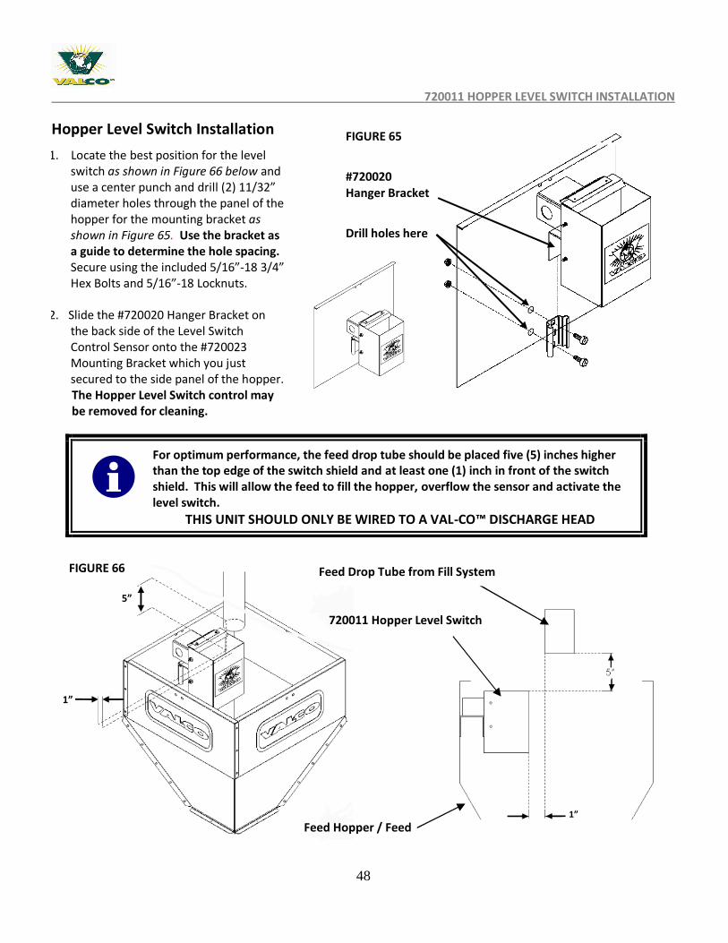
For optimum performance, the feed drop tube should be placed five (5) inches higher than the top edge of the switch shield and at least one (1) inch in front of the switch shield. This will allow the feed to fill the hopper, overflow the sensor and activate the level switch.
THIS UNIT SHOULD ONLY BE WIRED TO A VAL-CO™ DISCHARGE HEAD
1. Locate the best position for the level switch as shown in Figure 66 below and use a center punch and drill (2) 11/32” diameter holes through the panel of the hopper for the mounting bracket as shown in Figure 65. Use the bracket as a guide to determine the hole spacing. Secure using the included 5/16”-18 3/4” Hex Bolts and 5/16”-18 Locknuts.
2. Slide the #720020 Hanger Bracket on the back side of the Level Switch Control Sensor onto the #720023 Mounting Bracket which you just secured to the side panel of the hopper.
The Hopper Level Switch control may be removed for cleaning.
#720020 Hanger Bracket
1”
Feed Drop Tube from Fill System
720011 Hopper Level Switch
Feed Hopper / Feed
FIGURE 66
FIGURE 65
49
PART 10 – ANTI-ROOST INSTALLATION
PART 10 – ANTI-ROOST INSTALLATION
Anti-Roost Detailed
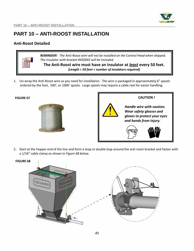
1. Un-wrap the Anti-Roost wire as you need for installation. The wire is packaged in approximately 6” spools ordered by the foot, 500’, or 1000’ spools. Large spools may require a cable reel for easier handling. 2. Start at the hopper end of the line and form a loop or double loop around the anti-roost bracket and fasten with
a 1/16” cable clamp as shown in Figure 68 below.
REMINDER! The Anti-Roost wire will not be installed on the Control Head when shipped. The insulator with bracket #450042 will be Included.
The Anti-Roost wire must have an insulator at least every 50 feet. (Length ÷ 50 feet = number of insulators required)
FIGURE 67 CAUTION !
Handle wire with caution. Wear safety glasses and gloves to protect your eyes and hands from injury.
FIGURE 68
50
ANTI-ROOST INSTALLATION
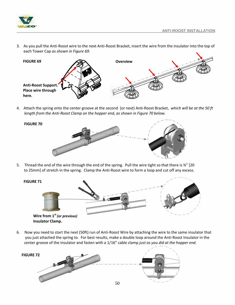
3. As you pull the Anti-Roost wire to the next Anti-Roost Bracket, insert the wire from the insulator into the top of each Tower Cap as shown in Figure 69.
4. Attach the spring onto the center groove at the second (or next) Anti-Roost Bracket, which will be at the 50 ft length from the Anti-Roost Clamp on the hopper end, as shown in Figure 70 below. 5. Thread the end of the wire through the end of the spring. Pull the wire tight so that there is ¾” *20 to 25mm] of stretch in the spring. Clamp the Anti-Roost wire to form a loop and cut off any excess.
6. Now you need to start the next (50ft) run of Anti-Roost Wire by attaching the wire to the same insulator that you just attached the spring to. For best results, make a double loop around the Anti-Roost Insulator in the center groove of the insulator and fasten with a 1/16” cable clamp just as you did at the hopper end.
Anti-Roost Support. Place wire through here.
FIGURE 69
Wire from 1st (or previous)
Insulator Clamp.
Overview
FIGURE 71
FIGURE 72
FIGURE 70
51
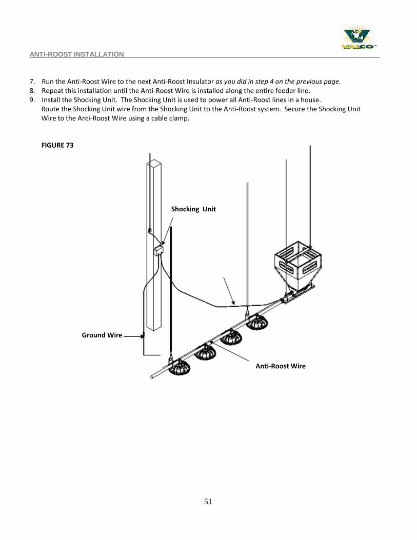
ANTI-ROOST INSTALLATION 7. Run the Anti-Roost Wire to the next Anti-Roost Insulator as you did in step 4 on the previous page. 8. Repeat this installation until the Anti-Roost Wire is installed along the entire feeder line. 9. Install the Shocking Unit. The Shocking Unit is used to power all Anti-Roost lines in a house. Route the Shocking Unit wire from the Shocking Unit to the Anti-Roost system. Secure the Shocking Unit Wire to the Anti-Roost Wire using a cable clamp.
FIGURE 73
Shocking Unit
Anti-Roost Wire
Ground Wire
52
PART 11 - MID HOUSE CONTROL INSTALLATION
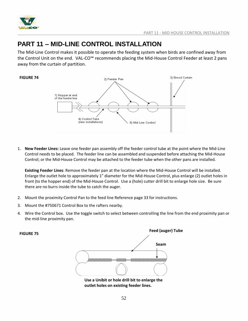
PART 11 – MID-LINE CONTROL INSTALLATION The Mid-Line Control makes it possible to operate the feeding system when birds are confined away from the Control Unit on the end. VAL-CO™ recommends placing the Mid-House Control Feeder at least 2 pans away from the curtain of partition.
1. New Feeder Lines: Leave one feeder pan assembly off the feeder control tube at the point where the Mid-Line
Control needs to be placed. The feeder line can be assembled and suspended before attaching the Mid-House Control; or the Mid-House Control may be attached to the feeder tube when the other pans are installed. Existing Feeder Lines: Remove the feeder pan at the location where the Mid-House Control will be installed. Enlarge the outlet hole to approximately 1” diameter for the Mid-House Control, plus enlarge (2) outlet holes in front (to the hopper end) of the Mid-House Control. Use a (hole) cutter drill bit to enlarge hole size. Be sure there are no burrs inside the tube to catch the auger.
2. Mount the proximity Control Pan to the feed line Reference page 33 for instructions.
3. Mount the #750671 Control Box to the rafters nearby.
4. Wire the Control box. Use the toggle switch to select between controlling the line from the end proximity pan or the mid-line proximity pan.
FIGURE 74
FIGURE 75
Use a Unibit or hole drill bit to enlarge the outlet holes on existing feeder lines.
Seam
Feed (auger) Tube
53
PART 12 – FEEDER OPERATION- ADJUSTING THE FEEDER SETTINGS
PART 12 - Operation Guidelines (Valco Broiler Feeding System)
Brood Stage, First (7-14) days:
1. Lower Feeder to the floor until the pans are resting on the floor and causing the feed flood windows to open and still allow the winch cable lines to remain taught. Do not rest complete system weight on the pan assemblies. It is best to warm up the house and litter at least 24 hours before bird placement.
2. Do not operate the feeder on full automatic when the windows are open. Once pans are flooded, remove power from system until next flooding is required at controller or breaker panel. Running the feeder on automatic with windows open will lead to excess feed waste.
3. Operate the feeders manually 1-3 times per day for the first 7 to 14 days as necessary to keep the pans full of feed, but not so full as to have excessive feed levels that allow the birds to waste feed. If it is not possible to operate the feeding system manually then a time clock should be employed to operate the feeder at predetermined times and to limit the run time of the feeding system.
4. If it is necessary to flood again, re-flooding the system should be scheduled while the lights are off and the birds are bedded down. This will minimize bird activity in the pan while the feeder is running resulting in minimized feed waste.
Grow-out Stage (7-14) days to Finish:
1. As the birds grow and become familiar with eating from the feeder pans it will become time to begin raising the feeder to the grow-out position.
2. As a starting point, set the feeder on the #4 adjustment position by rotating the grill on the collar to the desired position. Feed levels can be “fine tuned” from this setting as breed, and type of feed might dictate.
3. Allow the birds to eat the feed down below the feed windows. This will facilitate the closing of the feed windows as the feeder is raised.
4. Use the winch to raise the feeding system to a height where the lip of the pan is level with the “full portion” of the chicken’s breast. Again make adjustments to accommodate differences in breeds. It is important to initially raise the pans to just the point where they are no longer touching the floor. It may be noticed that some pans may appear “higher” or “lower”. This is not a condition for concern as the birds will level the litter.
5. Continue to raise the feeder as necessary to maintain the same relative position of the feeder pan lip to the bird’s breast until grow-out is completed.
These are to be used as general guidelines. Differences in breed, feed consistency, lighting, climate, and other external factors will dictate changes in these guidelines to individualize a broiler growing program to optimize feeding system performance.
54
APPENDIX 1 – FEEDER CLEANING AND MAINTENANCE
Appendix 1 – Feeder Cleaning and Maintenance
End of Grow-Out
Empty all pans at the end of grow-out.
Auger all feed out of the tubes. Winch up the complete feed system to remove the birds and manure.
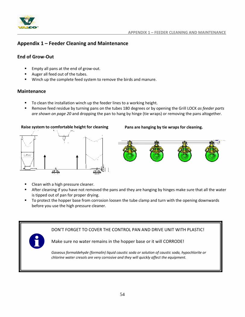
Maintenance
To clean the installation winch up the feeder lines to a working height. Remove feed residue by turning pans on the tubes 180 degrees or by opening the Grill LOCK as feeder parts
are shown on page 20 and dropping the pan to hang by hinge (tie wraps) or removing the pans altogether.
Clean with a high pressure cleaner. After cleaning if you have not removed the pans and they are hanging by hinges make sure that all the water
is tipped out of pan for proper drying. To protect the hopper base from corrosion loosen the tube clamp and turn with the opening downwards
before you use the high pressure cleaner.
DON’T FORGET TO COVER THE CONTROL PAN AND DRIVE UNIT WITH PLASTIC! Make sure no water remains in the hopper base or it will CORRODE! Gaseous formaldehyde (formalin) liquid caustic soda or solution of caustic soda, hypochlorite or chlorine water cresols are very corrosive and they will quickly affect the equipment.
Raise system to comfortable height for cleaning Pans are hanging by tie wraps for cleaning.
55
APPENDIX 2–FE1500LS FUZE FEEDER PARTS LIST
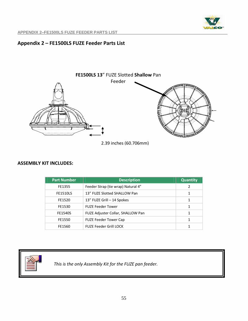
Appendix 2 – FE1500LS FUZE Feeder Parts List
ASSEMBLY KIT INCLUDES:
Part Number Description Quantity
FE1355 Feeder Strap (tie wrap) Natural 4” 2
FE1510LS 13” FUZE Slotted SHALLOW Pan 1
FE1520 13” FUZE Grill – 14 Spokes 1
FE1530 FUZE Feeder Tower 1
FE1540S FUZE Adjuster Collar, SHALLOW Pan 1
FE1550 FUZE Feeder Tower Cap 1
FE1560 FUZE Feeder Grill LOCK 1
FE1500LS 13” FUZE Slotted Shallow Pan Feeder
14 spoke grill
2.39 inches (60.706mm)
This is the only Assembly Kit for the FUZE pan feeder.
56
APPENDIX 3 – FE1500RS FUZE PROLINE FEEDER PARTS LIST
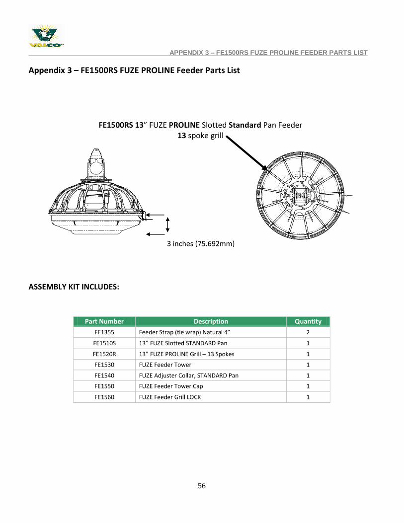
Appendix 3 – FE1500RS FUZE PROLINE Feeder Parts List
ASSEMBLY KIT INCLUDES:
Part Number Description Quantity
FE1355 Feeder Strap (tie wrap) Natural 4” 2
FE1510S 13” FUZE Slotted STANDARD Pan 1
FE1520R 13” FUZE PROLINE Grill – 13 Spokes 1
FE1530 FUZE Feeder Tower 1
FE1540 FUZE Adjuster Collar, STANDARD Pan 1
FE1550 FUZE Feeder Tower Cap 1
FE1560 FUZE Feeder Grill LOCK 1
FE1500RS 13” FUZE PROLINE Slotted Standard Pan Feeder 13 spoke grill
3 inches (75.692mm)
57
APPENDIX 4 – FE1500LRS FUZE PROLINE FEEDER PARTS LIST
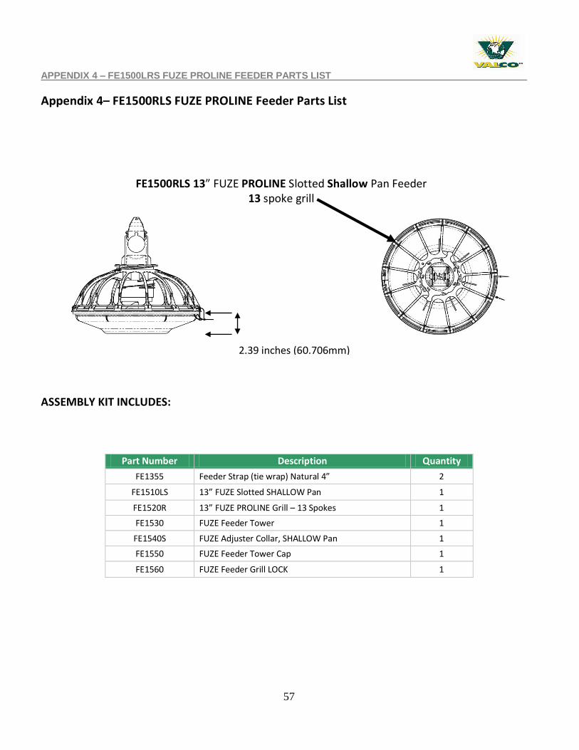
Appendix 4– FE1500RLS FUZE PROLINE Feeder Parts List
ASSEMBLY KIT INCLUDES:
Part Number Description Quantity
FE1355 Feeder Strap (tie wrap) Natural 4” 2
FE1510LS 13” FUZE Slotted SHALLOW Pan 1
FE1520R 13” FUZE PROLINE Grill – 13 Spokes 1
FE1530 FUZE Feeder Tower 1
FE1540S FUZE Adjuster Collar, SHALLOW Pan 1
FE1550 FUZE Feeder Tower Cap 1
FE1560 FUZE Feeder Grill LOCK 1
FE1500RLS 13” FUZE PROLINE Slotted Shallow Pan Feeder 13 spoke grill
2.39 inches (60.706mm)
58
APPENDIX 5 – FE1500RS FUZE PROLINE FEEDER PARTS LIST
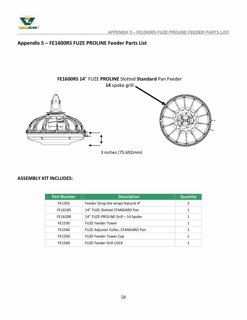
Appendix 5 – FE1600RS FUZE PROLINE Feeder Parts List
ASSEMBLY KIT INCLUDES:
Part Number Description Quantity
FE1355 Feeder Strap (tie wrap) Natural 4” 2
FE1610S 14” FUZE Slotted STANDARD Pan 1
FE1620R 14” FUZE PROLINE Grill – 14 Spoke 1
FE1530 FUZE Feeder Tower 1
FE1540 FUZE Adjuster Collar, STANDARD Pan 1
FE1550 FUZE Feeder Tower Cap 1
FE1560 FUZE Feeder Grill LOCK 1
FE1600RS 14” FUZE PROLINE Slotted Standard Pan Feeder 14 spoke grill
3 inches (75.692mm)
59
APPENDIX 6 – FE1600LRLS FUZE PROLINE FEEDER PARTS LIST
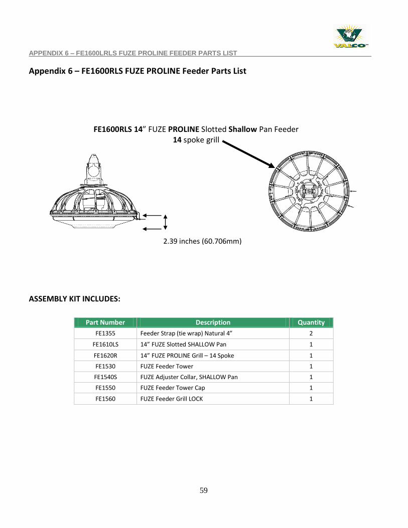
Appendix 6 – FE1600RLS FUZE PROLINE Feeder Parts List
ASSEMBLY KIT INCLUDES:
Part Number Description Quantity
FE1355 Feeder Strap (tie wrap) Natural 4” 2
FE1610LS 14” FUZE Slotted SHALLOW Pan 1
FE1620R 14” FUZE PROLINE Grill – 14 Spoke 1
FE1530 FUZE Feeder Tower 1
FE1540S FUZE Adjuster Collar, SHALLOW Pan 1
FE1550 FUZE Feeder Tower Cap 1
FE1560 FUZE Feeder Grill LOCK 1
FE1600RLS 14” FUZE PROLINE Slotted Shallow Pan Feeder 14 spoke grill
2.39 inches (60.706mm)
60
APPENDIX 7– FE1800RS FUZE PROLINE FEEDER PARTS LIST
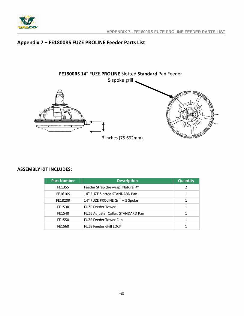
Appendix 7 – FE1800RS FUZE PROLINE Feeder Parts List
ASSEMBLY KIT INCLUDES:
Part Number Description Quantity
FE1355 Feeder Strap (tie wrap) Natural 4” 2
FE1610S 14” FUZE Slotted STANDARD Pan 1
FE1820R 14” FUZE PROLINE Grill – 5 Spoke 1
FE1530 FUZE Feeder Tower 1
FE1540 FUZE Adjuster Collar, STANDARD Pan 1
FE1550 FUZE Feeder Tower Cap 1
FE1560 FUZE Feeder Grill LOCK 1
FE1800RS 14” FUZE PROLINE Slotted Standard Pan Feeder 5 spoke grill
3 inches (75.692mm)
61
APPENDIX 8 – FE1800RLS FUZE PROLINE FEEDER PARTS LIST
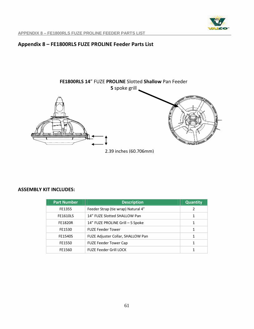
Appendix 8 – FE1800RLS FUZE PROLINE Feeder Parts List
ASSEMBLY KIT INCLUDES:
Part Number Description Quantity
FE1355 Feeder Strap (tie wrap) Natural 4” 2
FE1610LS 14” FUZE Slotted SHALLOW Pan 1
FE1820R 14” FUZE PROLINE Grill – 5 Spoke 1
FE1530 FUZE Feeder Tower 1
FE1540S FUZE Adjuster Collar, SHALLOW Pan 1
FE1550 FUZE Feeder Tower Cap 1
FE1560 FUZE Feeder Grill LOCK 1
FE1800RLS 14” FUZE PROLINE Slotted Shallow Pan Feeder 5 spoke grill
2.39 inches (60.706mm)
62
APPENDIX 9 – EXPLODED CONTROL PAN
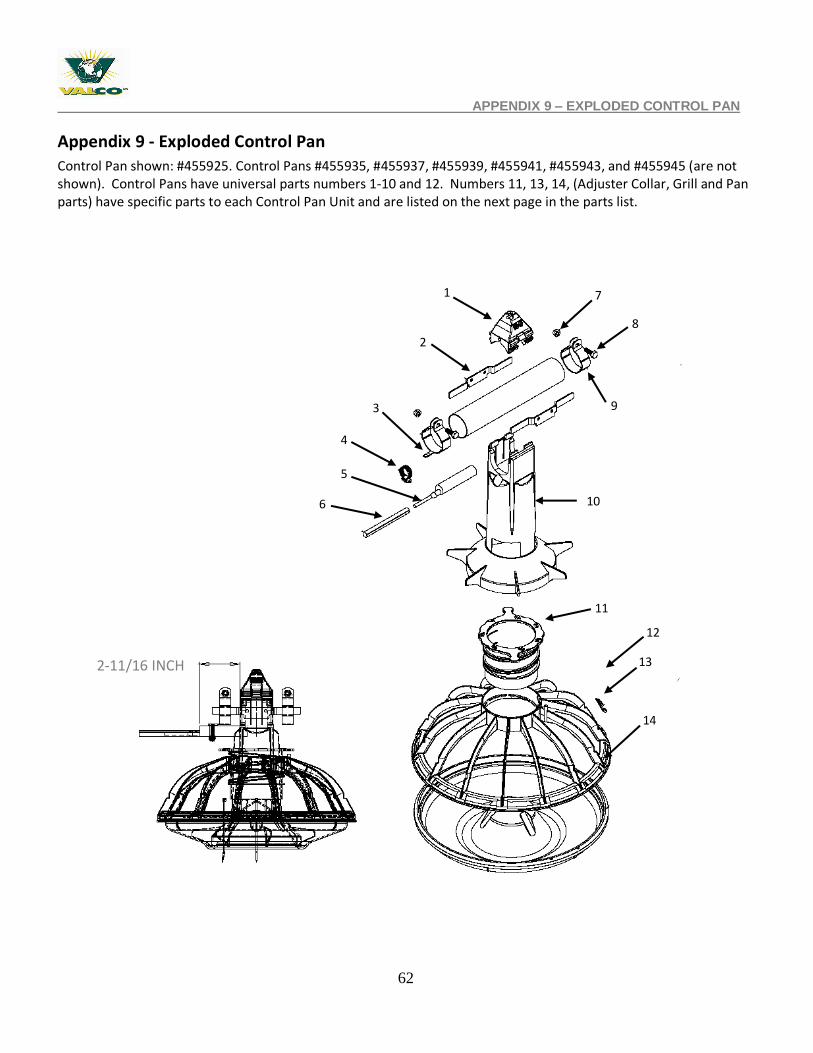
Appendix 9 - Exploded Control Pan
Control Pan shown: #455925. Control Pans #455935, #455937, #455939, #455941, #455943, and #455945 (are not shown). Control Pans have universal parts numbers 1-10 and 12. Numbers 11, 13, 14, (Adjuster Collar, Grill and Pan parts) have specific parts to each Control Pan Unit and are listed on the next page in the parts list.
7
2
3
4
5
6
8
9
10
11
13
12
14
1.
2-11/16 INCH
63
APPENDIX 9 – CONTROL PAN PARTS LIST
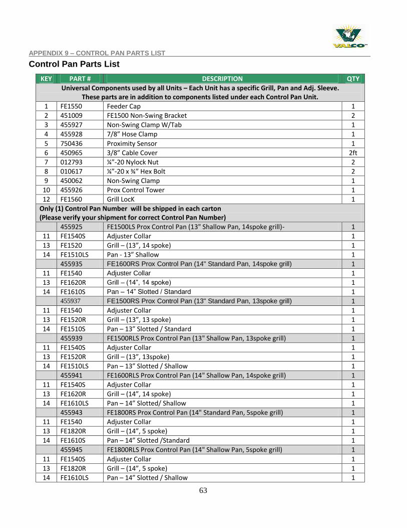
Control Pan Parts List
KEY PART # DESCRIPTION QTY
Universal Components used by all Units – Each Unit has a specific Grill, Pan and Adj. Sleeve. These parts are in addition to components listed under each Control Pan Unit.
1 FE1550 Feeder Cap 1
2 451009 FE1500 Non-Swing Bracket 2
3 455927 Non-Swing Clamp W/Tab 1
4 455928 7/8” Hose Clamp 1
5 750436 Proximity Sensor 1
6 450965 3/8” Cable Cover 2ft
7 012793 ¼”-20 Nylock Nut 2
8 010617 ¼”-20 x ¾” Hex Bolt 2
9 450062 Non-Swing Clamp 1
10 455926 Prox Control Tower 1
12 FE1560 Grill LocK 1
Only (1) Control Pan Number will be shipped in each carton (Please verify your shipment for correct Control Pan Number)
455925 FE1500LS Prox Control Pan (13" Shallow Pan, 14spoke grill)- 1
11 FE1540S Adjuster Collar 1
13 FE1520 Grill – (13”, 14 spoke) 1
14 FE1510LS Pan - 13” Shallow 1
455935 FE1600RS Prox Control Pan (14" Standard Pan, 14spoke grill) 1
11 FE1540 Adjuster Collar 1
13 FE1620R Grill – (14”, 14 spoke) 1
14 FE1610S Pan – 14” Slotted / Standard 1
455937 FE1500RS Prox Control Pan (13" Standard Pan, 13spoke grill) 1
11 FE1540 Adjuster Collar 1
13 FE1520R Grill – (13”, 13 spoke) 1
14 FE1510S Pan – 13” Slotted / Standard 1
455939 FE1500RLS Prox Control Pan (13" Shallow Pan, 13spoke grill) 1
11 FE1540S Adjuster Collar 1
13 FE1520R Grill – (13”, 13spoke) 1
14 FE1510LS Pan – 13” Slotted / Shallow 1
455941 FE1600RLS Prox Control Pan (14" Shallow Pan, 14spoke grill) 1
11 FE1540S Adjuster Collar 1
13 FE1620R Grill – (14”, 14 spoke) 1
14 FE1610LS Pan – 14” Slotted/ Shallow 1
455943 FE1800RS Prox Control Pan (14" Standard Pan, 5spoke grill) 1
11 FE1540 Adjuster Collar 1
13 FE1820R Grill – (14”, 5 spoke) 1
14 FE1610S Pan – 14” Slotted /Standard 1
455945 FE1800RLS Prox Control Pan (14" Shallow Pan, 5spoke grill) 1
11 FE1540S Adjuster Collar 1
13 FE1820R Grill – (14”, 5 spoke) 1
14 FE1610LS Pan – 14” Slotted / Shallow 1
64
APPENDIX 10 – DRIVE HEAD & GEARBOX UNIT PARTS LIST
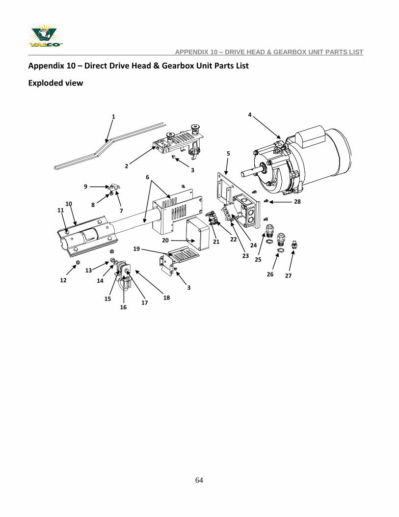
Appendix 10 – Direct Drive Head & Gearbox Unit Parts List
Exploded view
4
6
25
10
5
23
1
2
21
26
7
20
19
27
3
18
24
12
17
14
3
15
16
13
9
8 11
22
28
65
APPENDIX 10 – DRIVE HEAD & GEARBOX PARTS LIST
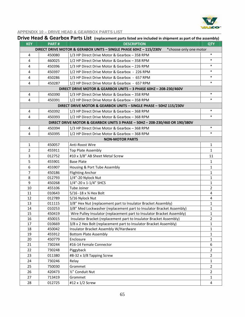
Drive Head & Gearbox Parts List (replacement parts listed are included in shipment as part of the assembly)
KEY PART # DESCRIPTION QTY
DIRECT DRIVE MOTOR & GERABOX UNITS – SINGLE PHASE 60HZ – 115/230V *choose only one motor
4 450080 1/3 HP Direct Drive Motor & Gearbox – 358 RPM *
4 460025 1/2 HP Direct Drive Motor & Gearbox – 358 RPM *
4 450396 1/3 HP Direct Drive Motor & Gearbox – 226 RPM *
4 450397 1/2 HP Direct Drive Motor & Gearbox - 226 RPM *
4 450286 1/3 HP Direct Drive Motor & Gearbox - 657 RPM *
4 450287 1/2 HP Direct Drive Motor & Gearbox - 657 RPM *
DIRECT DRIVE MOTOR & GEARBOX UNITS – 3 PHASE 60HZ – 208-230/460V
4 450390 1/3 HP Direct Drive Motor & Gearbox – 358 RPM *
4 450391 1/2 HP Direct Drive Motor & Gearbox – 358 RPM *
DIRECT DRIVE MOTOR & GEARBOX UNITS – SINGLE PHASE – 50HZ 115/230V
4 450392 1/3 HP Direct Drive Motor & Gearbox – 368 RPM *
4 450393 1/2 HP Direct Drive Motor & Gearbox – 368 RPM *
DIRECT DRIVE MOTOR & GEARBOX UNITS 3 PHASE – 50HZ – 208-230/460 OR 190/380V
4 450394 1/3 HP Direct Drive Motor & Gearbox – 368 RPM *
4 450395 1/2 HP Direct Drive Motor & Gearbox – 368 RPM *
NON-MOTOR PARTS
1 450057 Anti-Roost Wire 1
2 455911 Top Plate Assembly 1
3 012752 #10 x 3/8” AB Sheet Metal Screw 11
5 455901 Base Plate 1
6 455907 Housing & Port Tube Assembly 1
7 450186 Flighting Anchor 1
8 012793 1/4”-20 Nylock Nut 1
9 450268 1/4”-20 x 1-1/4” SHCS 1
10 455106 Tube Joiner 2
11 010643 5/16 -18 x ¾ Hex Bolt 4
12 012789 5/16 Nylock Nut 4
13 011115 3/8” Hex Nut (replacement part to Insulator Bracket Assembly) 1
14 010253 3/8” Med Lockwasher (replacement part to Insulator Bracket Assembly) 1
15 450419 Wire Pulley Insulator (replacement part to Insulator Bracket Assembly) 1
16 450015 Insulator Bracket (replacement part to Insulator Bracket Assembly) 2
17 010669 3/8 x 2 Hex Bolt (replacement part to Insulator Bracket Assembly) 1
18 450042 Insulator Bracket Assembly W/Hardware 1
19 455912 Bottom Plate Assembly 1
20 450779 Enclosure 1
21 730244 #16-14 Female Connector 6
22 730248 Piggyback 2
23 011380 #8-32 x 3/8 Tapping Screw 2
24 730246 Relay 1
25 750030 Grommet 2
26 420473 ½” Conduit Nut 2
27 713419 Grommet 1
28 012725 #12 x 1/2 Screw 4
66
APPENDIX 11 - FEED BOOT PARTS LIST
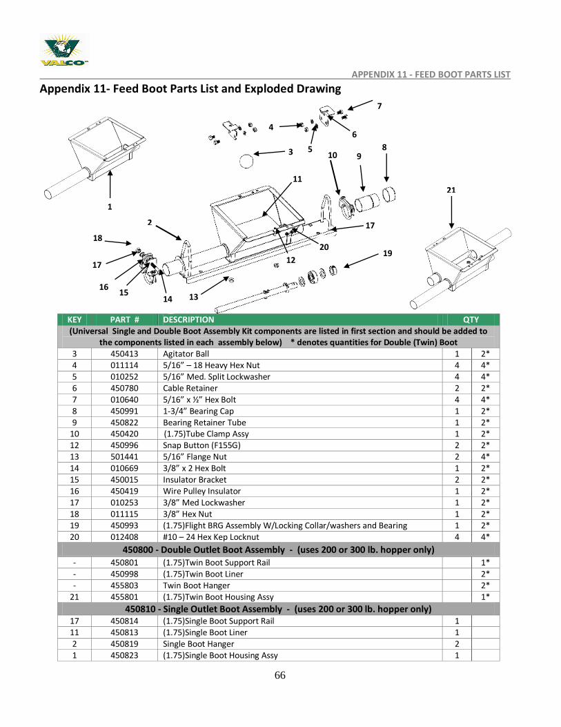
Appendix 11- Feed Boot Parts List and Exploded Drawing
KEY PART # DESCRIPTION QTY (Universal Single and Double Boot Assembly Kit components are listed in first section and should be added to
the components listed in each assembly below) * denotes quantities for Double (Twin) Boot 3 450413 Agitator Ball 1 2* 4 011114 5/16” – 18 Heavy Hex Nut 4 4* 5 010252 5/16” Med. Split Lockwasher 4 4* 6 450780 Cable Retainer 2 2* 7 010640 5/16” x ½” Hex Bolt 4 4* 8 450991 1-3/4” Bearing Cap 1 2* 9 450822 Bearing Retainer Tube 1 2*
10 450420 (1.75)Tube Clamp Assy 1 2* 12 450996 Snap Button (F155G) 2 2* 13 501441 5/16” Flange Nut 2 4* 14 010669 3/8” x 2 Hex Bolt 1 2* 15 450015 Insulator Bracket 2 2* 16 450419 Wire Pulley Insulator 1 2* 17 010253 3/8” Med Lockwasher 1 2* 18 011115 3/8” Hex Nut 1 2* 19 450993 (1.75)Flight BRG Assembly W/Locking Collar/washers and Bearing 1 2* 20 012408 #10 – 24 Hex Kep Locknut 4 4*
450800 - Double Outlet Boot Assembly - (uses 200 or 300 lb. hopper only) - 450801 (1.75)Twin Boot Support Rail 1* - 450998 (1.75)Twin Boot Liner 2* - 455803 Twin Boot Hanger 2*
21 455801 (1.75)Twin Boot Housing Assy 1*
450810 - Single Outlet Boot Assembly - (uses 200 or 300 lb. hopper only) 17 450814 (1.75)Single Boot Support Rail 1 11 450813 (1.75)Single Boot Liner 1 2 450819 Single Boot Hanger 2 1 450823 (1.75)Single Boot Housing Assy 1
2
3 8
12
21
19
11
9 10..
14
17
4
5
6
7
13
1
18
17
20
15 16
67
A PPENDIX 12 – REPLACEMENT OF FEED BOOT FLIGHTING ANCHOR & PARTS
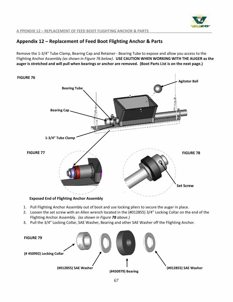
Appendix 12 – Replacement of Feed Boot Flighting Anchor & Parts
Remove the 1-3/4” Tube Clamp, Bearing Cap and Retainer - Bearing Tube to expose and allow you access to the Flighting Anchor Assembly (as shown in Figure 76 below). USE CAUTION WHEN WORKING WITH THE AUGER as the auger is stretched and will pull when bearings or anchor are removed. (Boot Parts List is on the next page.)
1. Pull Flighting Anchor Assembly out of boot and use locking pliers to secure the auger in place. 2. Loosen the set screw with an Allen wrench located in the (#012855) 3/4” Locking Collar on the end of the
Flighting Anchor Assembly. (as shown in Figure 78 above.) 3. Pull the 3/4” Locking Collar, SAE Washer, Bearing and other SAE Washer off the Flighting Anchor.
1-3/4” Tube Clamp
Bearing Cap
Bearing Tube
FIGURE 77 FIGURE 78
FIGURE 76
(# 450992) Locking Collar
(#012855) SAE Washer (#450979) Bearing
(#012855) SAE Washer
FIGURE 79
Agitator Ball
Set Screw
Exposed End of Flighting Anchor Assembly
68
APPENDIX 13- HOPPER ASSEMBLY & INSTALLATION
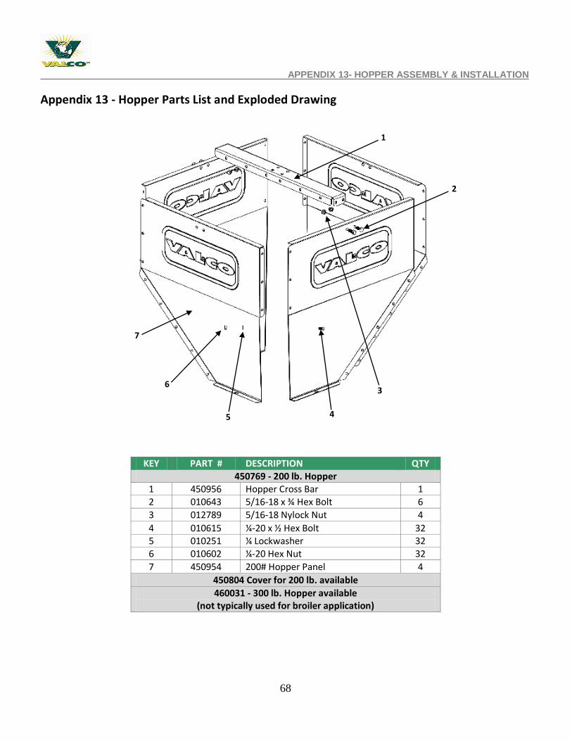
Appendix 13 - Hopper Parts List and Exploded Drawing
KEY PART # DESCRIPTION QTY 450769 - 200 lb. Hopper
1 450956 Hopper Cross Bar 1 2 010643 5/16-18 x ¾ Hex Bolt 6
3 012789 5/16-18 Nylock Nut 4
4 010615 ¼-20 x ½ Hex Bolt 32 5 010251 ¼ Lockwasher 32 6 010602 ¼-20 Hex Nut 32
7 450954 200# Hopper Panel 4
450804 Cover for 200 lb. available
460031 - 300 lb. Hopper available (not typically used for broiler application)
1
4
3
2
5
7
6
69
APPENDIX 14 - HOPPER LEVEL SWITCH CONTROL EXPLODED DRAWING
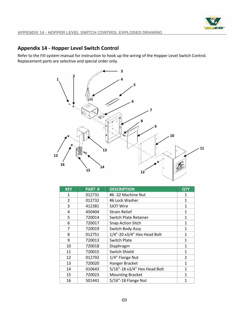
Appendix 14 - Hopper Level Switch Control
Refer to the Fill system manual for instruction to hook up the wiring of the Hopper Level Switch Control. Replacement parts are selective and special order only.
KEY PART # DESCRIPTION QTY 1 012731 #6 -32 Machine Nut 1 2 012732 #6 Lock Washer 1
3 412381 SJOT Wire 1
4 450404 Strain Relief 1 5 720014 Switch Plate Retainer 1 6 720017 Snap Action Sitch 1
7 720019 Switch Body Assy 1
8 012751 1/4”-20 x3/4” Hex Head Bolt 1
9 720013 Switch Plate 1
10 720018 Diaphragm 1
11 720015 Switch Shield 1
12 012792 1/4” Flange Nut 2
13 720020 Hanger Bracket 1
14 010643 5/16”-18 x3/4” Hex Head Bolt 1
15 720023 Mounting Bracket 1
16 501441 5/16”-18 Flange Nut 1
1 2
3
4
5
6
7
9
8
10
11
12 14
13
16
15
12
70
APPENDIX 15 – WINCH SYSTEM REPLACEMENT PARTS
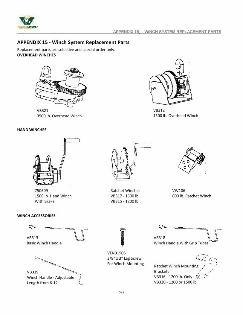
APPENDIX 15 - Winch System Replacement Parts
Replacement parts are selective and special order only. OVERHEAD WINCHES HAND WINCHES
WINCH ACCESSORIES
VB321 3500 lb. Overhead Winch
VB312 1500 lb. Overhead Winch
750609 1500 lb. Hand Winch With Brake
Ratchet Winches VB317 - 1500 lb. VB315 - 1200 lb.
VW106 600 lb. Ratchet Winch
VB313 Basic Winch Handle
VB318 Winch Handle With Grip Tubes
VB319 Winch Handle - Adjustable Length from 6-12'
VEN91505 3/8" x 3" Lag Screw For Winch Mounting
Ratchet Winch Mounting Brackets VB316 - 1200 lb. Only VB320 - 1200 or 1500 lb.
71
APPENDIX 15 – WINCH SYSTEM REPLACEMENT PARTS
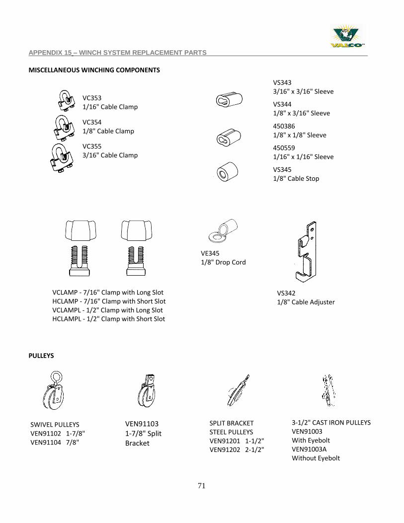
MISCELLANEOUS WINCHING COMPONENTS
PULLEYS
VEN91103 1-7/8" Split Bracket
SWIVEL PULLEYS VEN91102 1-7/8" VEN91104 7/8"
SPLIT BRACKET STEEL PULLEYS VEN91201 1-1/2" VEN91202 2-1/2"
3-1/2" CAST IRON PULLEYS VEN91003 With Eyebolt VEN91003A Without Eyebolt
VC353 1/16" Cable Clamp
VC354 1/8" Cable Clamp
VC355 3/16" Cable Clamp
VS343 3/16" x 3/16" Sleeve
VS344 1/8" x 3/16" Sleeve
450386 1/8" x 1/8" Sleeve
450559 1/16" x 1/16" Sleeve
VS345 1/8" Cable Stop
VCLAMP - 7/16" Clamp with Long Slot HCLAMP - 7/16" Clamp with Short Slot VCLAMPL - 1/2" Clamp with Long Slot HCLAMPL - 1/2" Clamp with Short Slot
VE345 1/8" Drop Cord Clamp
VS342 1/8" Cable Adjuster
72
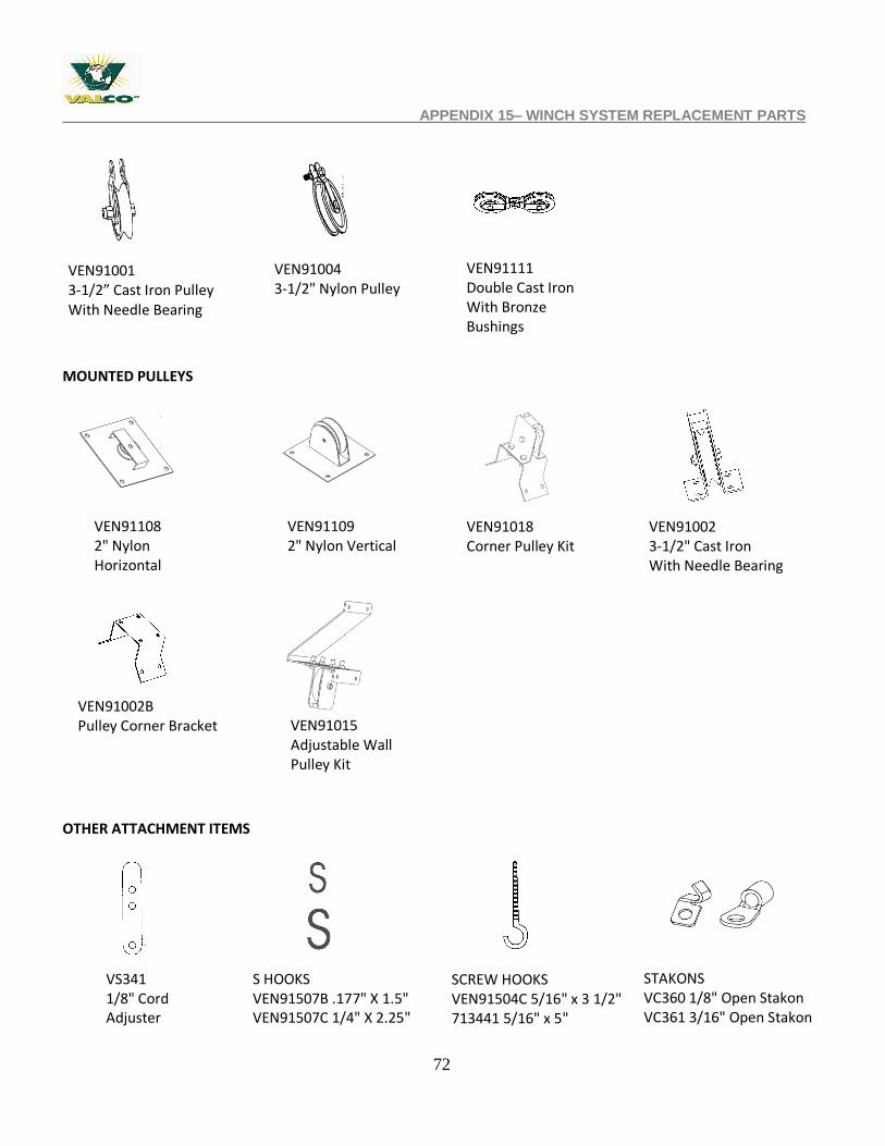
APPENDIX 15– WINCH SYSTEM REPLACEMENT PARTS MOUNTED PULLEYS
OTHER ATTACHMENT ITEMS
VEN91001 3-1/2” Cast Iron Pulley With Needle Bearing
VEN91004 3-1/2" Nylon Pulley
VEN91111 Double Cast Iron With Bronze Bushings
VEN91108 2" Nylon Horizontal
VEN91109 2" Nylon Vertical
VEN91018 Corner Pulley Kit
VEN91002 3-1/2" Cast Iron With Needle Bearing Bushing
VEN91002B Pulley Corner Bracket
VEN91015 Adjustable Wall Pulley Kit
VS341 1/8" Cord Adjuster
S HOOKS VEN91507B .177" X 1.5" VEN91507C 1/4" X 2.25"
SCREW HOOKS VEN91504C 5/16" x 3 1/2" 713441 5/16" x 5"
STAKONS VC360 1/8" Open Stakon VC361 3/16" Open Stakon
73
APPENDIX 16 – CUSTOMER SERVICE
Appendix 16 - CUSTOMER SERVICE
My dealer’s name: _____________________________________________________ How to contact my dealer:
Street/PO Box
City
State/Province
Zip/Postal
Phone
Fax
Web site
_____________________________
_____________________________
_____________________________
_____________________________
_____________________________
_____________________________
_____________________________
_____________________________
Customer Service 210 E. Main Street P.O. Box 117 Coldwater, OH 45828 800-998-2526
North America: Phone: 800.99VALCO (800.998.2526) Fax: 419.678.2200 Email: [email protected]
International: Phone: (+1) 419.678.8731 Fax: (+1) 419.678.2200 Email: [email protected]
Recommended