AG TREME TM
Utilizing
Technology
TMTrusted Difference at Ever y Turn
AGRICULTURAL BEARINGS
BEARING SOLUTIONS FOR THE AGRICULTURAL INDUSTRY

2 www.peerbearing.com
3
TMTrusted Difference at Ever y Turn
Contents
About PEER ....................................................................................................................................................................................................................................... 4
Agricultural industry .................................................................................................................................................................................................................... 5
PEER AGXTREME and agricultural bearing product range ........................................................................................................................................ 6
PEER product validation and sealing solution ................................................................................................................................................................ 7
Agricultural machinery and bearing application ........................................................................................................................................................... 8
Tillage Bearings .............................................................................................................................................................................................................................. 9
Application challenges ..................................................................................................................................................................................................10
Product table by application .......................................................................................................................................................................................12
Seeder Bearings ............................................................................................................................................................................................................................23
Application challenges ..................................................................................................................................................................................................24
Product table by application .......................................................................................................................................................................................26
Combine Bearings .......................................................................................................................................................................................................................31
Application challenges ..................................................................................................................................................................................................32
Product table by application .......................................................................................................................................................................................33
Baler Bearings ...............................................................................................................................................................................................................................37
Application challenges ..................................................................................................................................................................................................38
Product table by application .......................................................................................................................................................................................40
Implement wheel and walking beam.................................................................................................................................................................................48
4 www.peerbearing.com
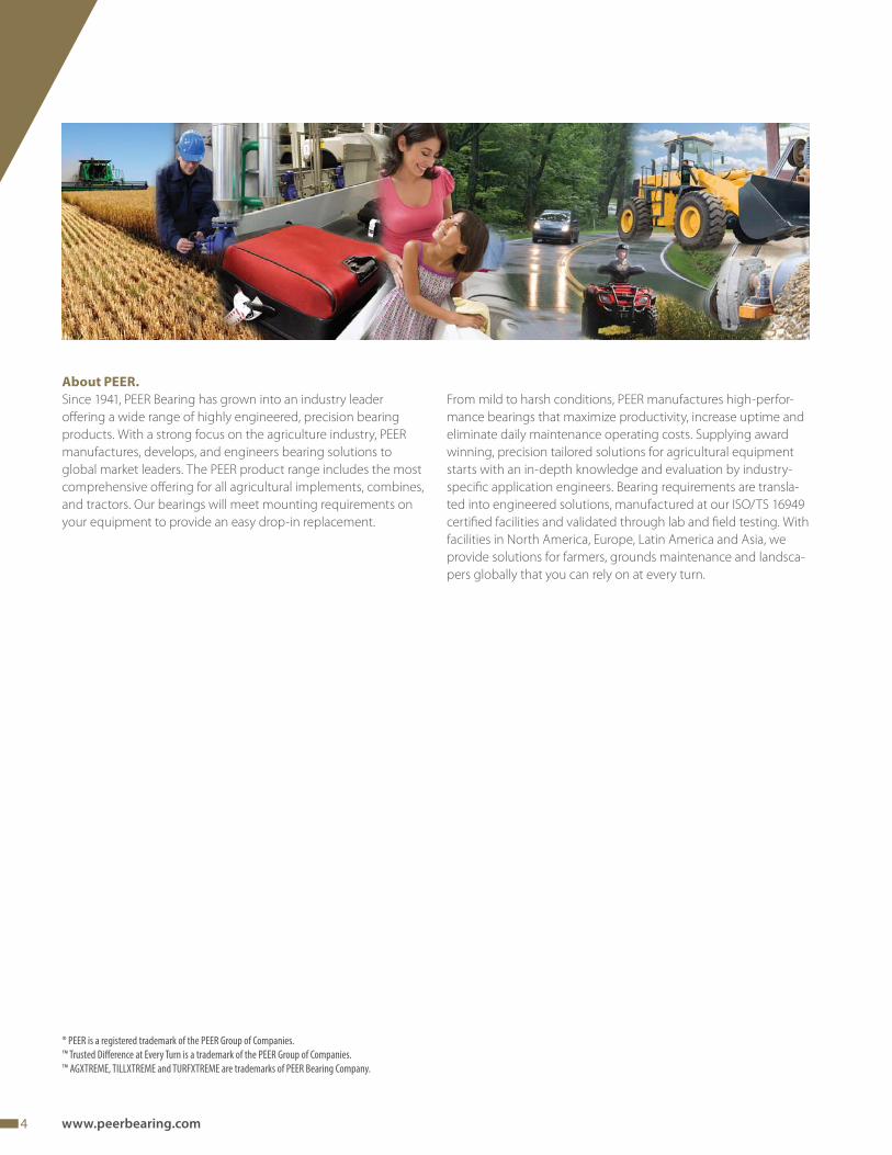
About PEER.
Since 1941, PEER Bearing has grown into an industry leader
off ering a wide range of highly engineered, precision bearing
products. With a strong focus on the agriculture industry, PEER
manufactures, develops, and engineers bearing solutions to
global market leaders. The PEER product range includes the most
comprehensive off ering for all agricultural implements, combines,
and tractors. Our bearings will meet mounting requirements on
your equipment to provide an easy drop-in replacement.
From mild to harsh conditions, PEER manufactures high-perfor-
mance bearings that maximize productivity, increase uptime and
eliminate daily maintenance operating costs. Supplying award
winning, precision tailored solutions for agricultural equipment
starts with an in-depth knowledge and evaluation by industry-
specifi c application engineers. Bearing requirements are transla-
ted into engineered solutions, manufactured at our ISO/TS 16949
certifi ed facilities and validated through lab and fi eld testing. With
facilities in North America, Europe, Latin America and Asia, we
provide solutions for farmers, grounds maintenance and landsca-
pers globally that you can rely on at every turn.
® PEER is a registered trademark of the PEER Group of Companies.
™ Trusted Diff erence at Every Turn is a trademark of the PEER Group of Companies.
™ AGXTREME, TILLXTREME and TURFXTREME are trademarks of PEER Bearing Company.
5
TMTrusted Difference at Ever y Turn
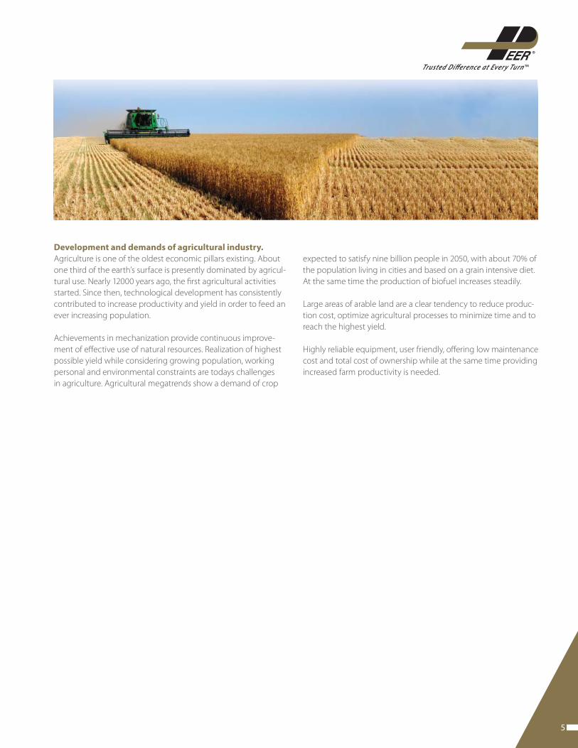
Development and demands of agricultural industry.
Agriculture is one of the oldest economic pillars existing. About
one third of the earth’s surface is presently dominated by agricul-
tural use. Nearly 12000 years ago, the fi rst agricultural activities
started. Since then, technological development has consistently
contributed to increase productivity and yield in order to feed an
ever increasing population.
Achievements in mechanization provide continuous improve-
ment of eff ective use of natural resources. Realization of highest
possible yield while considering growing population, working
personal and environmental constraints are todays challenges
in agriculture. Agricultural megatrends show a demand of crop
expected to satisfy nine billion people in 2050, with about 70% of
the population living in cities and based on a grain intensive diet.
At the same time the production of biofuel increases steadily.
Large areas of arable land are a clear tendency to reduce produc-
tion cost, optimize agricultural processes to minimize time and to
reach the highest yield.
Highly reliable equipment, user friendly, off ering low maintenance
cost and total cost of ownership while at the same time providing
increased farm productivity is needed.
6 www.peerbearing.com
maintenance-free, and simplify installation. As an environmentally
friendly solution, there is no grease purge to contaminate the soil.
SEEDXTREME™ off ers improved bearing solutions to support ma-
nufacturers of seeding equipment. Using our patented seal design
and optimized internal bearing construction, PEER off ers a range of
bearings specifi cally designed for gauge wheels, disc openers and
closing wheels, including integrated fl ange and shaft HUB design.
Whether you have to produce equipment that runs faster or carries
higher loads to cover the growing requirements for higher fi eld
productivity PEER SEEDXTREME™ bearings have been designed to
outperform the competition. These drop in replacements eliminate
the need for redesign and increase your speed to market.
TURFXTREME™ off ers the Lawn and Garden industries highest
performance bearing seal to provide contamination exclusion
and substantially increases the life of lawn and garden equip-
ment, requiring less frequent customer maintenance and greatly
reduced cost of machine ownership.
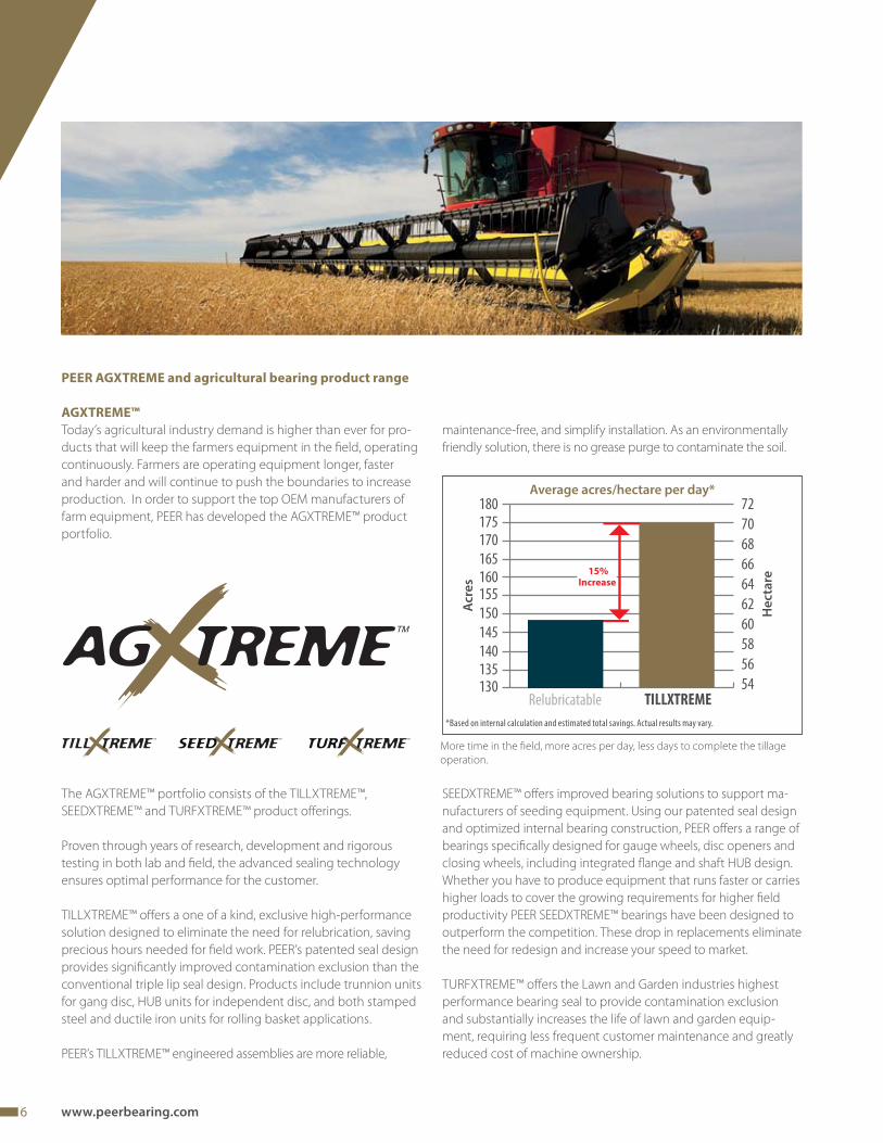
PEER AGXTREME and agricultural bearing product range
AGXTREME™
Today’s agricultural industry demand is higher than ever for pro-
ducts that will keep the farmers equipment in the fi eld, operating
continuously. Farmers are operating equipment longer, faster
and harder and will continue to push the boundaries to increase
production. In order to support the top OEM manufacturers of
farm equipment, PEER has developed the AGXTREME™ product
portfolio.
The AGXTREME™ portfolio consists of the TILLXTREME™,
SEEDXTREME™ and TURFXTREME™ product off erings.
Proven through years of research, development and rigorous
testing in both lab and fi eld, the advanced sealing technology
ensures optimal performance for the customer.
TILLXTREME™ off ers a one of a kind, exclusive high-performance
solution designed to eliminate the need for relubrication, saving
precious hours needed for fi eld work. PEER’s patented seal design
provides signifi cantly improved contamination exclusion than the
conventional triple lip seal design. Products include trunnion units
for gang disc, HUB units for independent disc, and both stamped
steel and ductile iron units for rolling basket applications.
PEER’s TILLXTREME™ engineered assemblies are more reliable,
TREMETURF TMTREMESEED TM
Average acres/hectare per day*
TILLXTREMERelubricatable130135140
145
150
155160165
170175180
54
56
58
60
62
64
66
68
70
72
15%
Increase
More time in the fi eld, more acres per day, less days to complete the tillage
operation.
*Based on internal calculation and estimated total savings. Actual results may vary.
He
cta
re
Acr
es
7
TMTrusted Difference at Ever y Turn
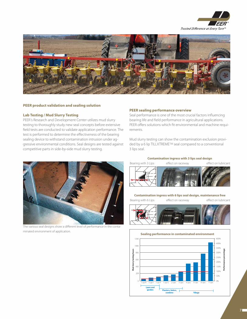
PEER product validation and sealing solution
Lab Testing / Mud Slurry Testing
PEER´s Research and Development Center utilizes mud slurry
testing to thoroughly study new seal concepts before extensive
fi eld tests are conducted to validate application performance. The
test is performed to determine the eff ectiveness of the bearing
sealing device to withstand contamination intrusion under ag-
gressive environmental conditions. Seal designs are tested against
competitive parts in side-by-side mud slurry testing.
PEER sealing performance overview
Seal performance is one of the most crucial factors infl uencing
bearing life and fi eld performance in agricultural applications.
PEER off ers solutions which fi t environmental and machine requi-
rements.
Mud slurry testing can show the contamination exclusion provi-
ded by a 6 lip TILLXTREMETM seal compared to a conventional
3 lips seal.
Contamination ingress with 3 lips seal design
Bearing with 3 Lips eff ect on raceway eff ect on lubricant
Contamination ingress with 6 lips seal design, maintenance free
Bearing with 6 Lips eff ect on raceway eff ect on lubricant
The various seal designs show a diff erent level of performance in the conta-
minated environment of application.
450%
400%
350%
300%
250%
200%
150%
100%
50%
0%1 Lip R 1 Lip Y 1 Lip F 1 Lip G 2 Lips 3 Lips 4 Lips 5 Lips 6 Lips 7 Lips
1200
1000
800
600
400
200
0
Lawn and
garden Planters, balers,
combine Tillage
Sealing performance in contaminated environment
Mu
d s
lurr
y t
est
ing
ho
urs
Pe
rfo
rma
nce
pe
rce
nta
ge
8 www.peerbearing.com
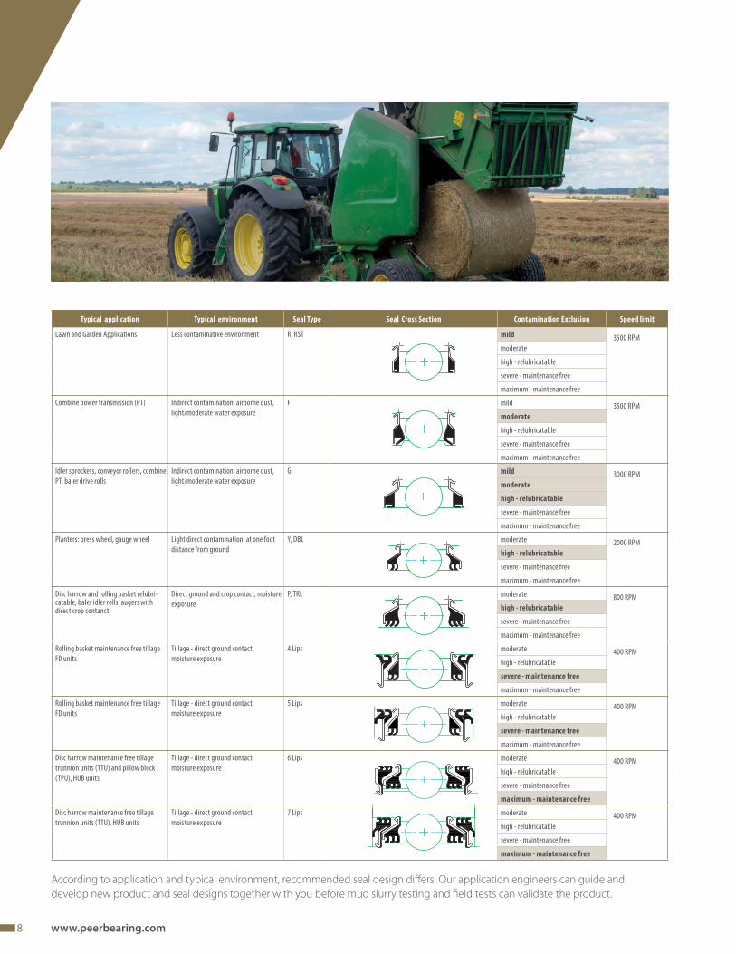
According to application and typical environment, recommended seal design diff ers. Our application engineers can guide and
develop new product and seal designs together with you before mud slurry testing and fi eld tests can validate the product.
Typical application Typical environment Seal Type Seal Cross Section Contamination Exclusion Speed limit
Lawn and Garden Applications Less contaminative environment R, RST mild 3500 RPM
moderate
high - relubricatable
severe - maintenance free
maximum - maintenance free
Combine power transmission (PT) Indirect contamination, airborne dust,
light/moderate water exposure
F mild 3500 RPM
moderate
high - relubricatable
severe - maintenance free
maximum - maintenance free
Idler sprockets, conveyor rollers, combine
PT, baler drive rolls
Indirect contamination, airborne dust,
light/moderate water exposure
G mild 3000 RPM
moderate
high - relubricatable
severe - maintenance free
maximum - maintenance free
Planters: press wheel, gauge wheel Light direct contamination, at one foot
distance from ground
Y, DBL moderate 2000 RPM
high - relubricatable
severe - maintenance free
maximum - maintenance free
Disc harrow and rolling basket relubri-catable, baler idler rolls, augers with direct crop contanct
Direct ground and crop contact, moisture
exposure
P, TRL moderate 800 RPM
high - relubricatable
severe - maintenance free
maximum - maintenance free
Rolling basket maintenance free tillage
FD units
Tillage - direct ground contact,
moisture exposure
4 Lips moderate 400 RPM
high - relubricatable
severe - maintenance free
maximum - maintenance free
Rolling basket maintenance free tillage
FD units
Tillage - direct ground contact,
moisture exposure
5 Lips moderate 400 RPM
high - relubricatable
severe - maintenance free
maximum - maintenance free
Disc harrow maintenance free tillage
trunnion units (TTU) and pillow block
(TPU), HUB units
Tillage - direct ground contact,
moisture exposure
6 Lips moderate 400 RPM
high - relubricatable
severe - maintenance free
maximum - maintenance free
Disc harrow maintenance free tillage
trunnion units (TTU), HUB units
Tillage - direct ground contact,
moisture exposure
7 Lips moderate 400 RPM
high - relubricatable
severe - maintenance free
maximum - maintenance free
9
TMTrusted Difference at Ever y Turn
Tillage Bearings
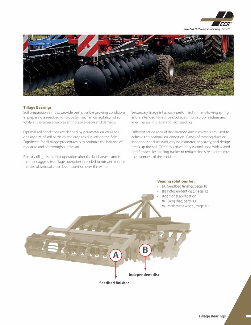
Soil preparation aims to provide best possible growing conditions
in preparing a seedbed for crops by mechanical agitation of soil
while at the same time preventing soil erosion and damage.
Optimal soil conditions are defi ned by parameters such as soil
density, size of soil particles and crop residue left on the fi eld.
Signifi cant for all tillage procedures is to optimize the balance of
moisture and air throughout the soil.
Primary tillage is the fi rst operation after the last harvest, and is
the most aggressive tillage operation intended to mix and reduce
the size of residual crop decomposition over the winter.
Secondary tillage is typically performed in the following spring
and is intended to reduce clod sizes, mix in crop residues and
level the soil in preparation for seeding.
Diff erent set designs of disc harrows and cultivators are used to
achieve this optimal soil condition. Gangs of rotating discs or
independent discs with varying diameter, concavity, and design
break up the soil. Often this machinery is combined with a seed-
bed fi nisher like a rolling basket to reduce clod size and improve
the evenness of the seedbed.
A
Bearing solutions for:
• (A) Seedbed fi nisher, page 18
• (B) Independent disc, page 12
• Additional application
Gang disc, page 13
Implement wheel, page 49
Seedbed fi nisher
B
Independent disc
Tillage Bearings
10 www.peerbearing.com
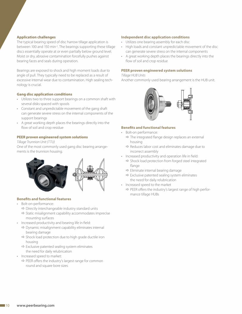
Application challenges
The typical bearing speed of disc harrow tillage application is
between 100 and 150 min-1. The bearings supporting these tillage
discs essentially operate at or even partially below ground level.
Moist or dry, abrasive contamination forcefully pushes against
bearing faces and seals during operation.
Bearings are exposed to shock and high moment loads due to
angle of pull. They typically need to be replaced as a result of
excessive internal wear due to contamination. High sealing tech-
nology is crucial.
Gang disc application conditions
• Utilizes two to three support bearings on a common shaft with
several disks spaced with spools
• Constant and unpredictable movement of the gang shaft
can generate severe stress on the internal components of the
support bearings
• A great working depth places the bearings directly into the
fl ow of soil and crop residue
PEER proven engineered system solutions
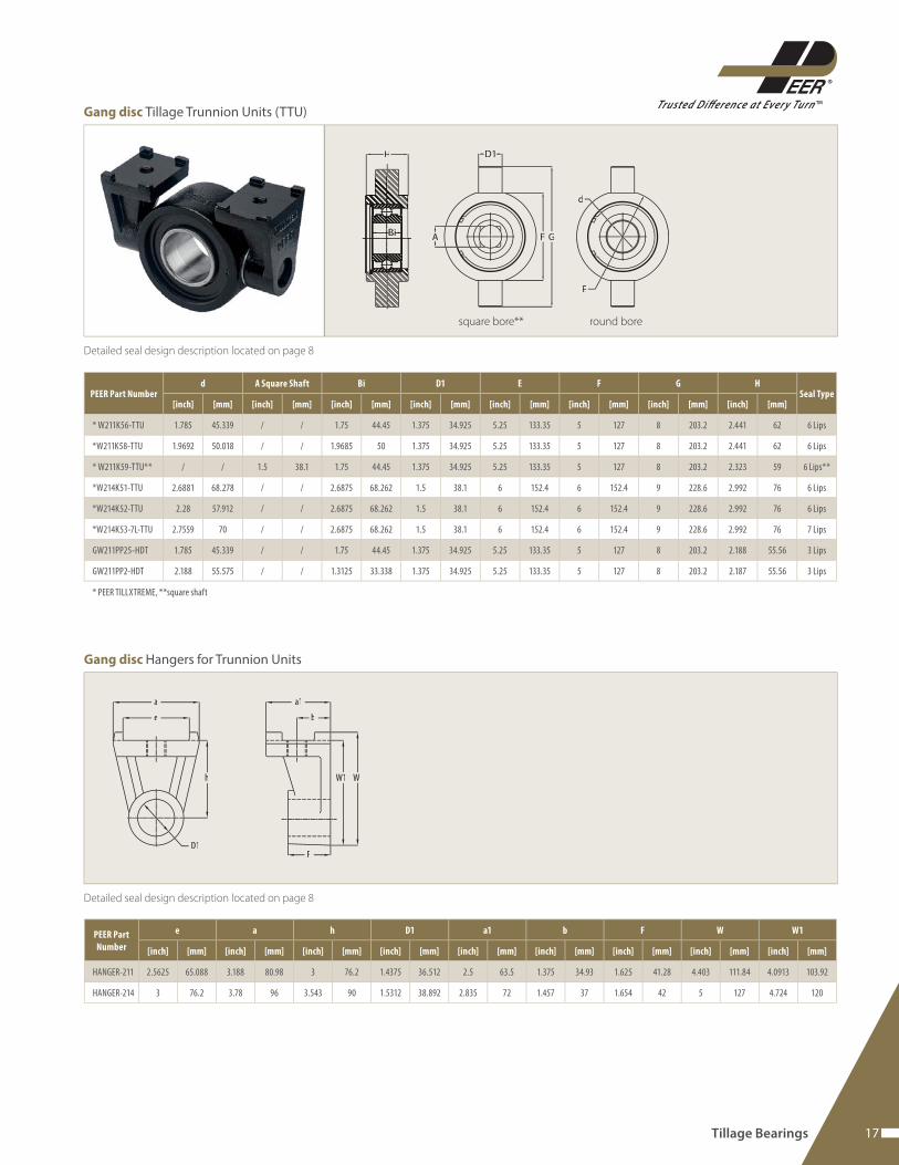
Tillage Trunnion Unit (TTU)
One of the most commonly used gang disc bearing arrange-
ments is the trunnion housing.
Benefi ts and functional features
• Bolt-on-performance:
Directly interchangeable industry standard units
Static misalignment capability accommodates imprecise
mounting surfaces
• Increased productivity and bearing life in fi eld:
Dynamic misalignment capability eliminates internal
bearing damage
Shock load protection due to high grade ductile iron
housing
Exclusive patented sealing system eliminates
the need for daily relubrication
• Increased speed to market:
PEER off ers the industry’s largest range for common
round and square bore sizes
Independent disc application conditions
• Utilizes one bearing assembly for each disc
• High loads and constant unpredictable movement of the disc
can generate severe stress on the internal components
• A great working depth places the bearings directly into the
fl ow of soil and crop residue
PEER proven engineered system solutions
Tillage HUB Units
Another commonly used bearing arrangement is the HUB unit.
Benefi ts and functional features
• Bolt-on performance:
The integrated fl ange design replaces an external
housing
Reduces labor cost and eliminates damage due to
incorrect assembly
• Increased productivity and operation life in fi eld:
Shock load protection from forged steel integrated
fl ange
Eliminate internal bearing damage
Exclusive patented sealing system eliminates
the need for daily relubrication
• Increased speed to the market
PEER off ers the industry’s largest range of high perfor-
mance tillage HUBs
11
TMTrusted Difference at Ever y Turn
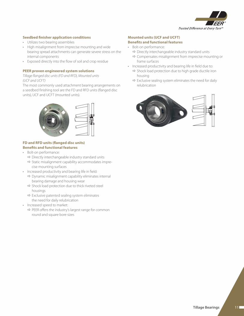
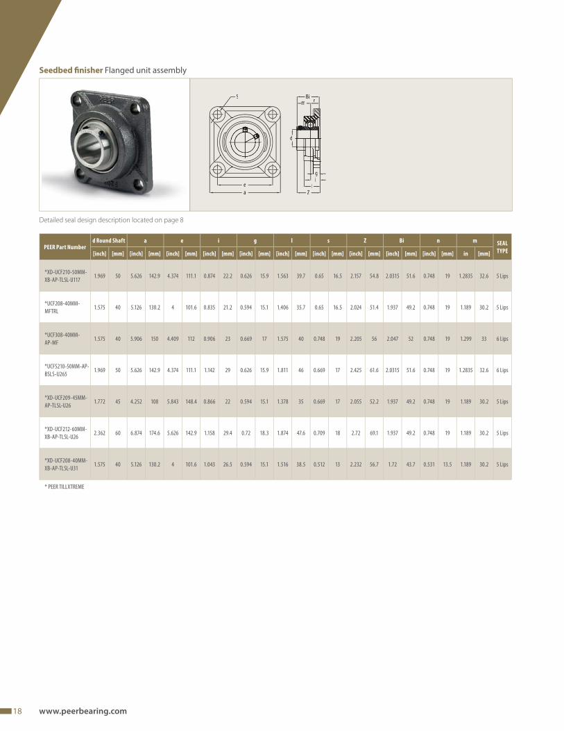
Seedbed fi nisher application conditions
• Utilizes two bearing assemblies
• High misalignment from imprecise mounting and wide
bearing spread attachments can generate severe stress on the
internal components
• Exposed directly into the fl ow of soil and crop residue
PEER proven engineered system solutions
Tillage fl anged disc units (FD and RFD), Mounted units
(UCF and UCFT)
The most commonly used attachment bearing arrangements on
a seedbed fi nishing tool are the FD and RFD units (fl anged disc
units), UCF and UCFT (mounted units).
FD and RFD units (fl anged disc units)
Benefi ts and functional features
• Bolt-on performance:
Directly interchangeable industry standard units
Static misalignment capability accommodates impre-
cise mounting surfaces
• Increased productivity and bearing life in fi eld:
Dynamic misalignment capability eliminates internal
bearing damage and housing wear
Shock load protection due to thick riveted steel
housings
Exclusive patented sealing system eliminates
the need for daily relubrication
• Increased speed to market:
PEER off ers the industry’s largest range for common
round and square bore sizes
Mounted units (UCF and UCFT)
Benefi ts and functional features
• Bolt-on performance:
Directly interchangeable industry standard units
Compensates misalignment from imprecise mounting or
frame surfaces
• Increased productivity and bearing life in fi eld due to:
Shock load protection due to high grade ductile iron
housing
Exclusive sealing system eliminates the need for daily
relubrication
Tillage Bearings
12 www.peerbearing.com
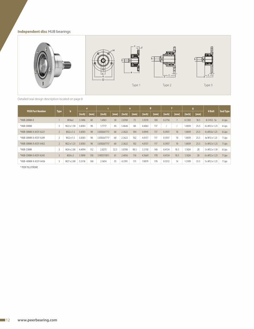
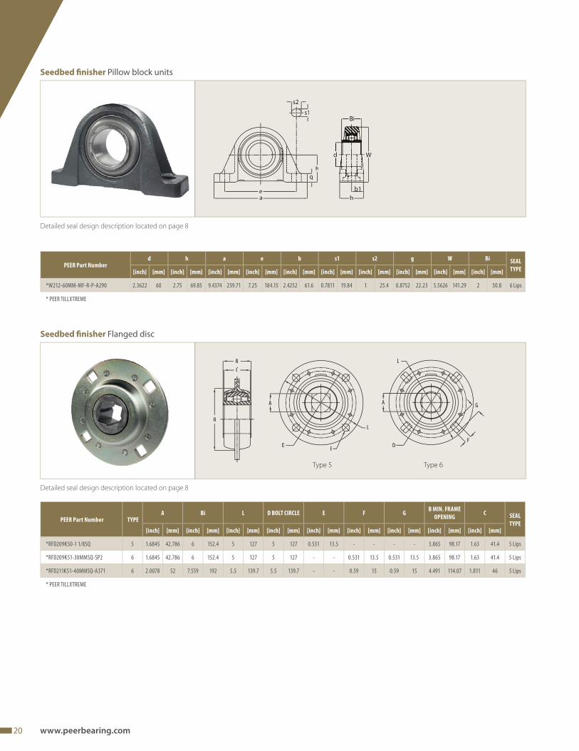
Detailed seal design description located on page 8
Independent disc HUB bearings
b
cf
H
geD
b
ac f
b
c fa
Type 2 Type 3Type 1
PEER Part Number Type be c a D f g
H Bolt Seal Type[inch] [mm] [inch] [mm] [inch] [mm] [inch] [mm] [inch] [mm] [inch] [mm]
*HUB-20MM-X 1 M16x2 3.1496 80 1.4961 38 2.8740 73 3.9370 100 0.2756 7 0.7283 18.5 8.5 H12. 5x 6 Lips
*HUB-30MM 3 M22 x 1.50 3.8583 98 1.7717 45 3.4646 88 4.6063 117 / / 1.0039 25.5 4 x M12 x 1.25 6 Lips
*HUB-30MM-X-ASSY-A221 2 M22 x 1.5 3.8583 98 3.858267717 60 2.3622 104 4.0945 117 0.3937 10 1.0039 25.5 4 x M12x 1.25 6 Lips
*HUB-30MM-X-ASSY-A249 2 M22 x 1.5 3.8583 98 3.858267717 60 2.3622 102 4.0157 117 0.3937 10 1.0039 25.5 6x M12 x 1.25 7 Lips
*HUB-30MM-X-ASSY-A452 2 M22 x 1.25 3.8583 98 3.858267717 60 2.3622 102 4.0157 117 0.3937 10 1.0039 25.5 5 x M12 x 1.25 7 Lips
*HUB-35MM 3 M24 x 2.00 4.4094 112 2.0275 52.5 3.8780 98.5 5.5118 140 0.4134 10.5 1.1024 28 5 x M12 x 1.50 6 Lips
*HUB-35MM-X-ASSY-A243 3 M24 x 2 3.1890 150 5.905511811 61 2.4016 116 4.5669 178 0.4134 10.5 1.1024 28 6 x M12 x 1.25 7 Lips
*HUB-40MM-X-ASSY-A436 3 M27 x 2.00 5.5118 140 2.1654 55 4.3701 111 7.0079 178 0.5512 14 1.3189 33.5 5 x M12 x 1.25 7 Lips
* PEER TILLXTREME
13
TMTrusted Difference at Ever y Turn
Tillage Bearings
Detailed seal design description located on page 8
BiBe
BiBe
Bi
Be
Bi
Be
D D D D D
Bi
Be
A
Type 2 Type 4Type 3Type 1
Gang disc Standard relubricatable bearings, square bore
Type 5
PEER Part Number TypeA D Bi Be
Seal Type[inch] [mm] [inch] [mm] [inch] [mm] [inch] [mm]
GW208PP17 4 1.1800 29.972 3.3755 85.738 1.4375 36.512 1.1875 30.162 3 Lips
GW208PPB5 1 1.1800 29.972 3.1496 80 1.4375 36.512 0.8268 21 3 Lips
GW208PPB8 1 1.1800 29.972 3.1496 80 1.4375 36.512 1.1875 30.162 3 Lips
GW210PP54 4 1.9380 49.225 3.5433 90 1.9375 49.212 0.7874 20 3 Lips
GW210PPB4 3 1.1580 29.413 3.5433 90 1.1875 30.162 1.1875 30.162 3 Lips
GW211PP17 4 1.5310 38.887 3.9370 100 1.7500 44.45 1.3120 33.325 3 Lips
GW211PP3-GX 5 1.5310 38.887 3.9370 100 1.3120 33.325 1.3120 33.325 3 Lips
GW211PPB3 3 1.5310 38.887 3.9370 100 1.3125 33.338 1.3125 33.338 3 Lips
GW212PP50-GX 4 1.7900 45.466 4.3307 110 2.0000 50.8 1.5060 38.252 3 Lips
GW214PPB4-GX 3 2.0551 52.2 4.9213 125 1.5625 39.688 1.5625 39.688 3 Lips
GW216PP2-GX 4 2.3125 58.738 5.5118 140 2.5000 63.5 1.1811 30 3 Lips
14 www.peerbearing.com
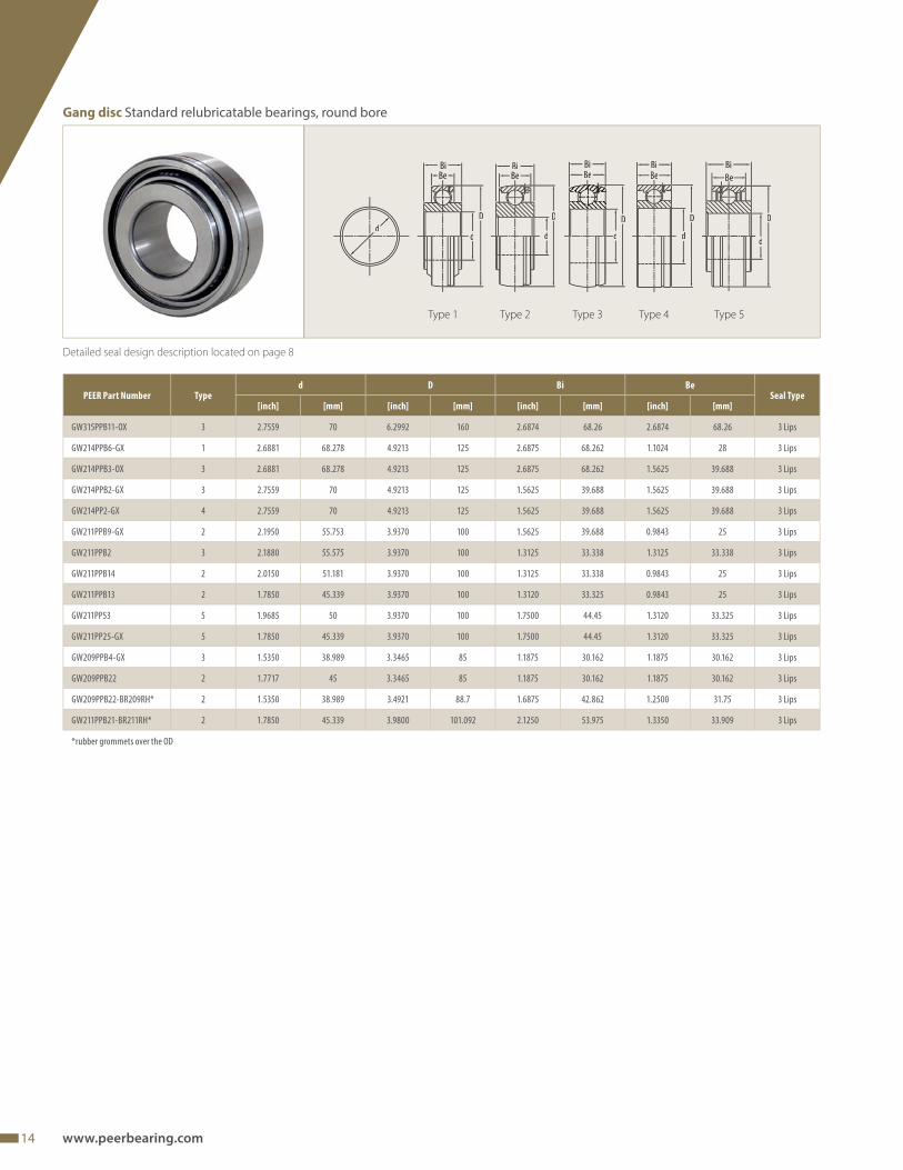
Detailed seal design description located on page 8
d
BiBe
BiBe
BiBe
BiBe
D D D D
d d d d
D
d
Be
Bi
Type 2 Type 4Type 3Type 1
Gang disc Standard relubricatable bearings, round bore
Type 5
PEER Part Number Typed D Bi Be
Seal Type[inch] [mm] [inch] [mm] [inch] [mm] [inch] [mm]
GW315PPB11-OX 3 2.7559 70 6.2992 160 2.6874 68.26 2.6874 68.26 3 Lips
GW214PPB6-GX 1 2.6881 68.278 4.9213 125 2.6875 68.262 1.1024 28 3 Lips
GW214PPB3-OX 3 2.6881 68.278 4.9213 125 2.6875 68.262 1.5625 39.688 3 Lips
GW214PPB2-GX 3 2.7559 70 4.9213 125 1.5625 39.688 1.5625 39.688 3 Lips
GW214PP2-GX 4 2.7559 70 4.9213 125 1.5625 39.688 1.5625 39.688 3 Lips
GW211PPB9-GX 2 2.1950 55.753 3.9370 100 1.5625 39.688 0.9843 25 3 Lips
GW211PPB2 3 2.1880 55.575 3.9370 100 1.3125 33.338 1.3125 33.338 3 Lips
GW211PPB14 2 2.0150 51.181 3.9370 100 1.3125 33.338 0.9843 25 3 Lips
GW211PPB13 2 1.7850 45.339 3.9370 100 1.3120 33.325 0.9843 25 3 Lips
GW211PP53 5 1.9685 50 3.9370 100 1.7500 44.45 1.3120 33.325 3 Lips
GW211PP25-GX 5 1.7850 45.339 3.9370 100 1.7500 44.45 1.3120 33.325 3 Lips
GW209PPB4-GX 3 1.5350 38.989 3.3465 85 1.1875 30.162 1.1875 30.162 3 Lips
GW209PPB22 2 1.7717 45 3.3465 85 1.1875 30.162 1.1875 30.162 3 Lips
GW209PPB22-BR209RH* 2 1.5350 38.989 3.4921 88.7 1.6875 42.862 1.2500 31.75 3 Lips
GW211PPB21-BR211RH* 2 1.7850 45.339 3.9800 101.092 2.1250 53.975 1.3350 33.909 3 Lips
*rubber grommets over the OD
15
TMTrusted Difference at Ever y Turn
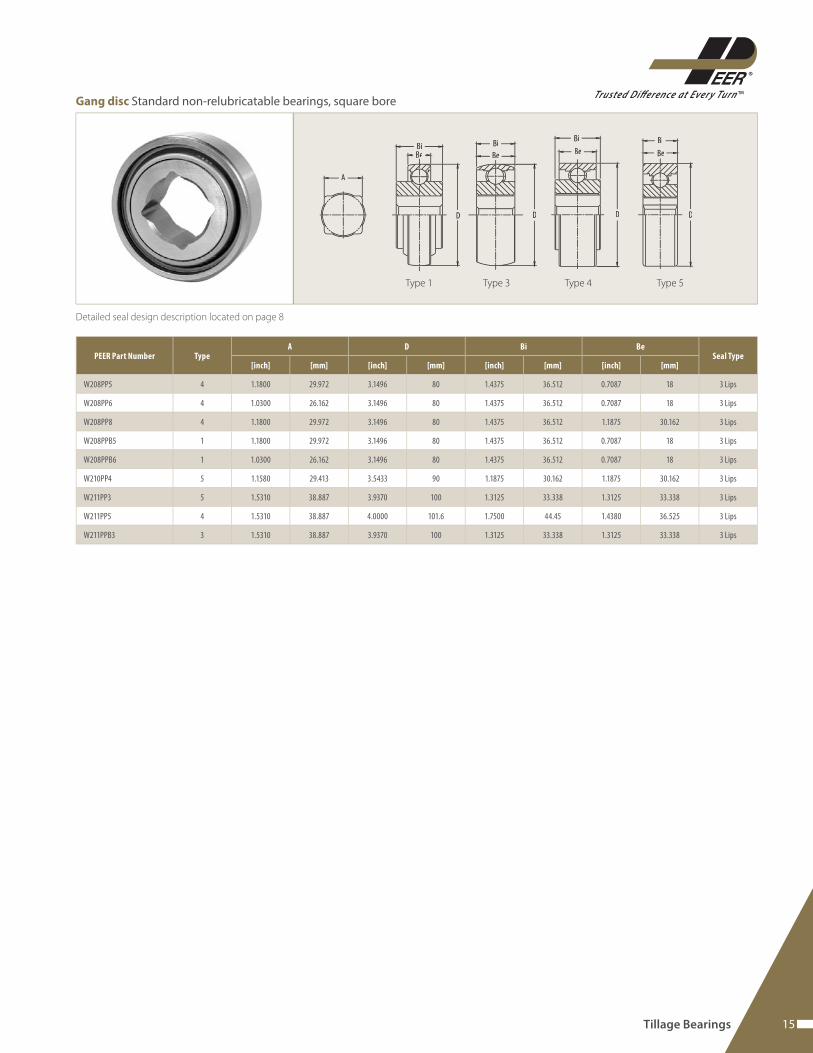
Detailed seal design description located on page 8
A
BiBe
Bi
Be
Bi
Be
Bi
Be
D D D D
PEER Part Number TypeA D Bi Be
Seal Type[inch] [mm] [inch] [mm] [inch] [mm] [inch] [mm]
W208PP5 4 1.1800 29.972 3.1496 80 1.4375 36.512 0.7087 18 3 Lips
W208PP6 4 1.0300 26.162 3.1496 80 1.4375 36.512 0.7087 18 3 Lips
W208PP8 4 1.1800 29.972 3.1496 80 1.4375 36.512 1.1875 30.162 3 Lips
W208PPB5 1 1.1800 29.972 3.1496 80 1.4375 36.512 0.7087 18 3 Lips
W208PPB6 1 1.0300 26.162 3.1496 80 1.4375 36.512 0.7087 18 3 Lips
W210PP4 5 1.1580 29.413 3.5433 90 1.1875 30.162 1.1875 30.162 3 Lips
W211PP3 5 1.5310 38.887 3.9370 100 1.3125 33.338 1.3125 33.338 3 Lips
W211PP5 4 1.5310 38.887 4.0000 101.6 1.7500 44.45 1.4380 36.525 3 Lips
W211PPB3 3 1.5310 38.887 3.9370 100 1.3125 33.338 1.3125 33.338 3 Lips
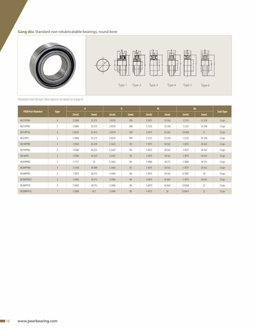
Gang disc Standard non-relubricatable bearings, square bore
Tillage Bearings
Type 3 Type 5Type 4Type 1
16 www.peerbearing.com
Detailed seal design description located on page 8
dD
Bi
d D
Bi
d
BiBe
D
BiBe
d D
BiBe
dD
Bi
d
Gang disc Standard non-relubricatable bearings, round bore
Type 3 Type 5Type 4Type 2 Type 6Type 1
PEER Part Number Typed D Bi Be
Seal Type[inch] [mm] [inch] [mm] [inch] [mm] [inch] [mm]
W211PPB4 6 2.1880 55.575 3.9370 100 2.1875 55.562 1.3125 33.338 3 Lips
W211PPB2 3 2.1880 55.575 3.9370 100 1.3125 33.338 1.3125 33.338 3 Lips
W211PP54 4 2.0635 52.413 3.9370 100 2.1875 55.562 0.8268 21 3 Lips
W211PP2 5 2.1880 55.575 3.9370 100 1.3125 33.338 1.3125 33.338 3 Lips
W210PPB5 3 1.7850 45.339 3.5433 90 1.1875 30.162 1.1875 30.162 3 Lips
W210PPB2 3 1.9380 49.225 3.5433 90 1.1875 30.162 1.1875 30.162 3 Lips
W210PP2 5 1.9380 49.225 3.5433 90 1.1875 30.162 1.1875 30.162 3 Lips
W209PPB2 3 1.7717 45 3.3465 85 1.1880 30.175 1.1880 30.175 3 Lips
W209PPB4 3 1.5350 38.989 3.3465 85 1.1875 30.162 1.1875 30.162 3 Lips
W208PPB7 2 1.1879 30.172 3.1496 80 1.1875 30.162 0.7087 18 3 Lips
W208PPB23 2 1.5005 38.113 3.1496 80 1.6875 42.862 1.1875 30.162 3 Lips
W208PP10 4 1.5005 38.113 3.1496 80 1.6875 42.862 0.8268 21 3 Lips
W208KPP53 1 1.5000 38.1 3.1496 80 1.4173 36 0.8661 22 3 Lips
17
TMTrusted Difference at Ever y Turn
Detailed seal design description located on page 8
PEER Part Numberd A Square Shaft Bi D1 E F G H
Seal Type[inch] [mm] [inch] [mm] [inch] [mm] [inch] [mm] [inch] [mm] [inch] [mm] [inch] [mm] [inch] [mm]
* W211K56-TTU 1.785 45.339 / / 1.75 44.45 1.375 34.925 5.25 133.35 5 127 8 203.2 2.441 62 6 Lips
*W211K58-TTU 1.9692 50.018 / / 1.9685 50 1.375 34.925 5.25 133.35 5 127 8 203.2 2.441 62 6 Lips
* W211K59-TTU** / / 1.5 38.1 1.75 44.45 1.375 34.925 5.25 133.35 5 127 8 203.2 2.323 59 6 Lips**
*W214K51-TTU 2.6881 68.278 / / 2.6875 68.262 1.5 38.1 6 152.4 6 152.4 9 228.6 2.992 76 6 Lips
*W214K52-TTU 2.28 57.912 / / 2.6875 68.262 1.5 38.1 6 152.4 6 152.4 9 228.6 2.992 76 6 Lips
*W214K53-7L-TTU 2.7559 70 / / 2.6875 68.262 1.5 38.1 6 152.4 6 152.4 9 228.6 2.992 76 7 Lips
GW211PP25-HDT 1.785 45.339 / / 1.75 44.45 1.375 34.925 5.25 133.35 5 127 8 203.2 2.188 55.56 3 Lips
GW211PP2-HDT 2.188 55.575 / / 1.3125 33.338 1.375 34.925 5.25 133.35 5 127 8 203.2 2.187 55.56 3 Lips
* PEER TILLXTREME, **square shaft
Detailed seal design description located on page 8
WW1
a a1
e
D1
h
b
F
PEER Part
Number
e a h D1 a1 b F W W1
[inch] [mm] [inch] [mm] [inch] [mm] [inch] [mm] [inch] [mm] [inch] [mm] [inch] [mm] [inch] [mm] [inch] [mm]
HANGER-211 2.5625 65.088 3.188 80.98 3 76.2 1.4375 36.512 2.5 63.5 1.375 34.93 1.625 41.28 4.403 111.84 4.0913 103.92
HANGER-214 3 76.2 3.78 96 3.543 90 1.5312 38.892 2.835 72 1.457 37 1.654 42 5 127 4.724 120
H
A
D1
F G
E
d
Gang disc Tillage Trunnion Units (TTU)
Gang disc Hangers for Trunnion Units
Tillage Bearings
square bore** round bore
18 www.peerbearing.com
Detailed seal design description located on page 8
Bi
d
e
a
S
il
Z
m n
PEER Part Numberd Round Shaft a e i g l s Z Bi n m SEAL
TYPE[inch] [mm] [inch] [mm] [inch] [mm] [inch] [mm] [inch] [mm] [inch] [mm] [inch] [mm] [inch] [mm] [inch] [mm] [inch] [mm] in [mm]
*XD-UCF210-50MM-
XB-AP-TLSL-U1171.969 50 5.626 142.9 4.374 111.1 0.874 22.2 0.626 15.9 1.563 39.7 0.65 16.5 2.157 54.8 2.0315 51.6 0.748 19 1.2835 32.6 5 Lips
*UCF208-40MM-
MFTRL1.575 40 5.126 130.2 4 101.6 0.835 21.2 0.594 15.1 1.406 35.7 0.65 16.5 2.024 51.4 1.937 49.2 0.748 19 1.189 30.2 5 Lips
*UCF308-40MM-
AP-MF1.575 40 5.906 150 4.409 112 0.906 23 0.669 17 1.575 40 0.748 19 2.205 56 2.047 52 0.748 19 1.299 33 6 Lips
*UCFS210-50MM-AP-
BSLS-U2651.969 50 5.626 142.9 4.374 111.1 1.142 29 0.626 15.9 1.811 46 0.669 17 2.425 61.6 2.0315 51.6 0.748 19 1.2835 32.6 6 Lips
*XD-UCF209-45MM-
AP-TLSL-U261.772 45 4.252 108 5.843 148.4 0.866 22 0.594 15.1 1.378 35 0.669 17 2.055 52.2 1.937 49.2 0.748 19 1.189 30.2 5 Lips
*XD-UCF212-60MM-
XB-AP-TLSL-U262.362 60 6.874 174.6 5.626 142.9 1.158 29.4 0.72 18.3 1.874 47.6 0.709 18 2.72 69.1 1.937 49.2 0.748 19 1.189 30.2 5 Lips
*XD-UCF208-40MM-
XB-AP-TLSL-U311.575 40 5.126 130.2 4 101.6 1.043 26.5 0.594 15.1 1.516 38.5 0.512 13 2.232 56.7 1.72 43.7 0.531 13.5 1.189 30.2 5 Lips
* PEER TILLXTREME
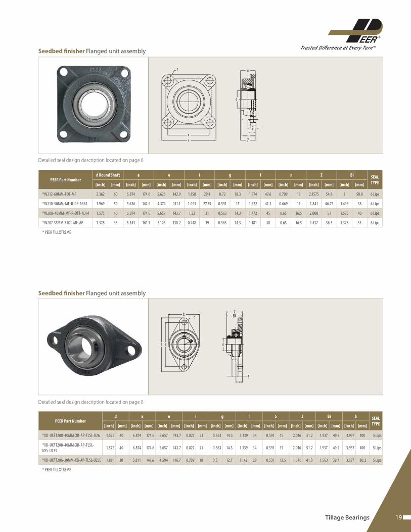
Seedbed fi nisher Flanged unit assembly
19
TMTrusted Difference at Ever y Turn
Detailed seal design description located on page 8
Bi
d
g
ea
S
il
Z
PEER Part Numberd Round Shaft a e i g l s Z Bi SEAL
TYPE[inch] [mm] [inch] [mm] [inch] [mm] [inch] [mm] [inch] [mm] [inch] [mm] [inch] [mm] [inch] [mm] [inch] [mm]
*W212-60MM-FDT-MF 2.362 60 6.874 174.6 5.626 142.9 1.158 29.4 0.72 18.3 1.874 47.6 0.709 18 2.1575 54.8 2 50.8 6 Lips
*W210-50MM-MF-R-DF-A362 1.969 50 5.626 142.9 4.374 111.1 1.093 27.75 0.591 15 1.622 41.2 0.669 17 1.841 46.75 1.496 38 6 Lips
*W208-40MM-MF-R-DFT-A374 1.575 40 6.874 174.6 5.657 143.7 1.22 31 0.563 14.3 1.772 45 0.65 16.5 2.008 51 1.575 40 6 Lips
*W207-35MM-FTDT-MF-AP 1.378 35 6.343 161.1 5.126 130.2 0.748 19 0.563 14.3 1.181 30 0.65 16.5 1.437 36.5 1.378 35 6 Lips
* PEER TILLXTREME
Detailed seal design description located on page 8
Sb
a e d
gl
BiZ
PEER Part Numberd a e i g l S Z Bi b SEAL
TYPE[inch] [mm] [inch] [mm] [inch] [mm] [inch] [mm] [inch] [mm] [inch] [mm] [inch] [mm] [inch] [mm] [inch] [mm] [inch] [mm]
*XD-UCFT208-40MM-XB-AP-TLSL-U26 1.575 40 6.874 174.6 5.657 143.7 0.827 21 0.563 14.3 1.339 34 0.591 15 2.016 51.2 1.937 49.2 3.937 100 5 Lips
*XD-UCFT208-40MM-XB-AP-TLSL-
NSS-U2391.575 40 6.874 174.6 5.657 143.7 0.827 21 0.563 14.3 1.339 34 0.591 15 2.016 51.2 1.937 49.2 3.937 100 5 Lips
*XD-UCFT206-30MM-XB-AP-TLSL-U236 1.181 30 5.811 147.6 4.594 116.7 0.709 18 0.5 12.7 1.142 29 0.531 13.5 1.646 41.8 1.563 39.7 3.157 80.2 5 Lips
* PEER TILLXTREME
Seedbed fi nisher Flanged unit assembly
Seedbed fi nisher Flanged unit assembly
Tillage Bearings
20 www.peerbearing.com
Detailed seal design description located on page 8
W
b1b
s1
s2
hg
ea
PEER Part Numberd h a e b s1 s2 g W Bi SEAL
TYPE[inch] [mm] [inch] [mm] [inch] [mm] [inch] [mm] [inch] [mm] [inch] [mm] [inch] [mm] [inch] [mm] [inch] [mm] [inch] [mm]
*W212-60MM-MF-R-P-A290 2.3622 60 2.75 69.85 9.4374 239.71 7.25 184.15 2.4252 61.6 0.7811 19.84 1 25.4 0.8752 22.23 5.5626 141.29 2 50.8 6 Lips
* PEER TILLXTREME
Detailed seal design description located on page 8
PEER Part Number TYPEA Bi L D BOLT CIRCLE E F G
B MIN. FRAME
OPENINGC SEAL
TYPE[inch] [mm] [inch] [mm] [inch] [mm] [inch] [mm] [inch] [mm] [inch] [mm] [inch] [mm] [inch] [mm] [inch] [mm]
*RFD209K50-1 1/8SQ 5 1.6845 42.786 6 152.4 5 127 5 127 0.531 13.5 - - - - 3.865 98.17 1.63 41.4 5 Lips
*RFD209K51-30MMSQ-SP2 6 1.6845 42.786 6 152.4 5 127 5 127 - - 0.531 13.5 0.531 13.5 3.865 98.17 1.63 41.4 5 Lips
*RFD211K51-40MMSQ-A371 6 2.0078 52 7.559 192 5.5 139.7 5.5 139.7 - - 0.59 15 0.59 15 4.491 114.07 1.811 46 5 Lips
* PEER TILLXTREME
Bi
C
B
D D
A A
L
L
E
F
G
Type 5 Type 6
Seedbed fi nisher Pillow block units
Seedbed fi nisher Flanged disc

21
TMTrusted Difference at Ever y Turn
Detailed seal design description located on page 8 Round Bore Non Relubricatable
PEER Part Number TYPEA/d Bi L D BOLT CIRCLE E F G
B MIN. FRAME
OPENINGC SEAL
TYPE[inch] [mm] [inch] [mm] [inch] [mm] [inch] [mm] [inch] [mm] [inch] [mm] [inch] [mm] [inch] [mm] [inch] [mm]
*FD209K58-1-3/4RD-A326 2 1.77 44.958 1.6845 42.786 5 127 5 127 0.531 13.487 - - - - 3.865 98.17 1.63 41.4 5 Lips
*FD209K50-1-3/4RD 2 1.77 49.958 1.747 44.374 5 127 5 127 0.531 13.487 - - - - 3.865 98.17 1.63 41.4 5 Lips
*FD209K52-1-1/2RD 4 1.535 38.989 1.6845 42.786 5 127 5 127 - - 0.531 13.487 0.687 17.45 3.865 98.17 1.63 41.4 5 Lips
*FD209K53-1-1/2RD 4 1.535 38.989 1.6845 42.786 5 127 5 127 - - 0.531 13.487 0.687 17.45 3.865 98.17 - - 6 Lips
*FD209K54-1-1/4RD 2 1.27 32.258 1.6845 42.786 5 127 5 127 0.531 13.487 - - - - 3.865 98.17 1.63 41.4 5 Lips
*FD211K65-1-15/16RDC-A326 2 1.938 49.253 2.125 53.975 139.7 5.5 5.5 139.7 0.531 13.487 - - - - 4.491 114.07 1.811 46 5 Lips
*FD211K51-1-3/4RD-A366 3 1.78 45.212 2.1875 55.5625 5.5 139.7 5.5 139.7 - - 0.531 13.49 0.687 17.45 4.491 114.07 1.811 46 5 Lips
*FD211K52-1-3/4RD-A365 2 1.78 45.212 2.1875 55.562 5.5 139.7 5.5 139.7 0.531 13.49 - - - - 4.491 114.07 1.811 46 5 Lips
*FD211K61-2-3/16RD 2 2.188 55.575 2.1845 55.486 5.5 139.7 5.5 139.7 0.531 13.487 - - - - 4.491 114.07 1.811 46 5 Lips
*FD212K51-60RD 2 2.4016 61 2.2047 56 6.811 173 5.63 143 6.4 16.25 - - - - 5 127 1.968 50 5 Lips
* PEER TILLXTREME
Square Bore Non-Relubricatable
PEER Part Number TYPEA/d Bi L D BOLT CIRCLE E F G
B MIN. FRAME
OPENINGC SEAL
TYPE[inch] [mm] [inch] [mm] [inch] [mm] [inch] [mm] [inch] [mm] [inch] [mm] [inch] [mm] [inch] [mm] [inch] [mm]
*FD209K51-1-1/4SQ 3 1.6845 42.786 5 127 5 127 5 127 - - 0.531 13.487 0.687 17.45 3.865 98.17 1.63 41.4 5 Lips
*FD209K57-1-1/8SQ-A366 3 1.6845 42.786 5 127 5 127 5 127 - - 0.531 13.487 0.687 17.45 3.865 98.17 1.63 41.4 5 Lips
*FD209K51-1-1/4SQ 3 1.3 33.02 1.6845 42.786 5 127 5 127 0.531 13.487 0.687 17.45 3.865 98.17 1.63 41.4 - - 5 Lips
*FD211K53-1-1/2SQ 3 2 50.8 5.5 139.7 5.5 139.7 5.5 139.7 - - 0.531 13.49 0.687 17.45 4.491 114.07 1.811 46 5 Lips
* PEER TILLXTREME
Bi
C
B
D
L L
F
G
d
L
F
G
D
Type 2 Type 4Type 3
Seedbed fi nisher Flanged disc
Tillage Bearings

22 www.peerbearing.com
Detailed seal design description located on page 8
Round Bore Relubricatable
PEER Part Number TYPEA/d Bi L D BOLT CIRCLE E F G
B MIN. FRAME
OPENINGC SEAL
TYPE[inch] [mm] [inch] [mm] [inch] [mm] [inch] [mm] [inch] [mm] [inch] [mm] [inch] [mm] [inch] [mm] [inch] [mm]
FD211-1-3/4RD 2 1.78 45.212 2.1875 55.563 5.5 139.7 5.5 139.7 0.531 13.49 - - - - 4.491 114.07 1.811 46 3 Lips
FD211-2-3/16RD 2 2.188 55.575 2.1845 55.486 5.5 139.7 5.5 139.7 0.531 13.487 - - - - 4.491 114.07 1.811 46 3 Lips
FD211-1-15/16RDC 2 1.938 49.225 2.125 53.975 5.5 139.7 5.5 139.7 0.531 13.487 - - - - 4.491 114.07 1.811 46 3 Lips
ST491A 2 1.77 44.958 1.6845 42.786 5 127 5 127 0.531 13.487 - - - - 3.865 98.17 - - 3 Lips
ST491A-B 2 1.77 44.958 1.747 44.374 5 127 5 127 0.531 13.487 - - - - 3.865 98.17 1.63 41.4 3 Lips
ST491B 4 1.535 38.989 1.6845 42.786 5 127 5 127 - - 0.531 13.487 0.687 17.45 3.865 98.17 1.63 41.4 3 Lips
Square Bore Relubricatable
PEER Part Number TYPEA/d Bi L D BOLT CIRCLE E F G
B MIN. FRAME
OPENINGC SEAL
TYPE[inch] [mm] [inch] [mm] [inch] [mm] [inch] [mm] [inch] [mm] [inch] [mm] [inch] [mm] [inch] [mm] [inch] [mm]
FD209-1-1/4SQ 3 1.3 33.02 1.6845 42.786 5 127 5 127 - - 0.531 13.5 0.687 17.45 3.865 98.17 1.63 41.4 3 Lips
FD209-1-1/8SQ 3 1.18 29.972 1.6845 42.786 5 127 5 127 - - 0.531 13.5 0.687 17.45 3.865 98.17 1.63 41.4 3 Lips
FD211-1-1/2SQ 3 1.531 38.887 2 50.8 5.5 139.7 5.5 139.7 - - 0.531 13.5 0.687 17.45 4.491 114.07 1.811 46 3 Lips
Bi
C
B
D
L L
F
G
d
L
F
G
D
Type 2 Type 4Type 3
Seedbed fi nisher Flanged disc
23
TMTrusted Difference at Ever y Turn
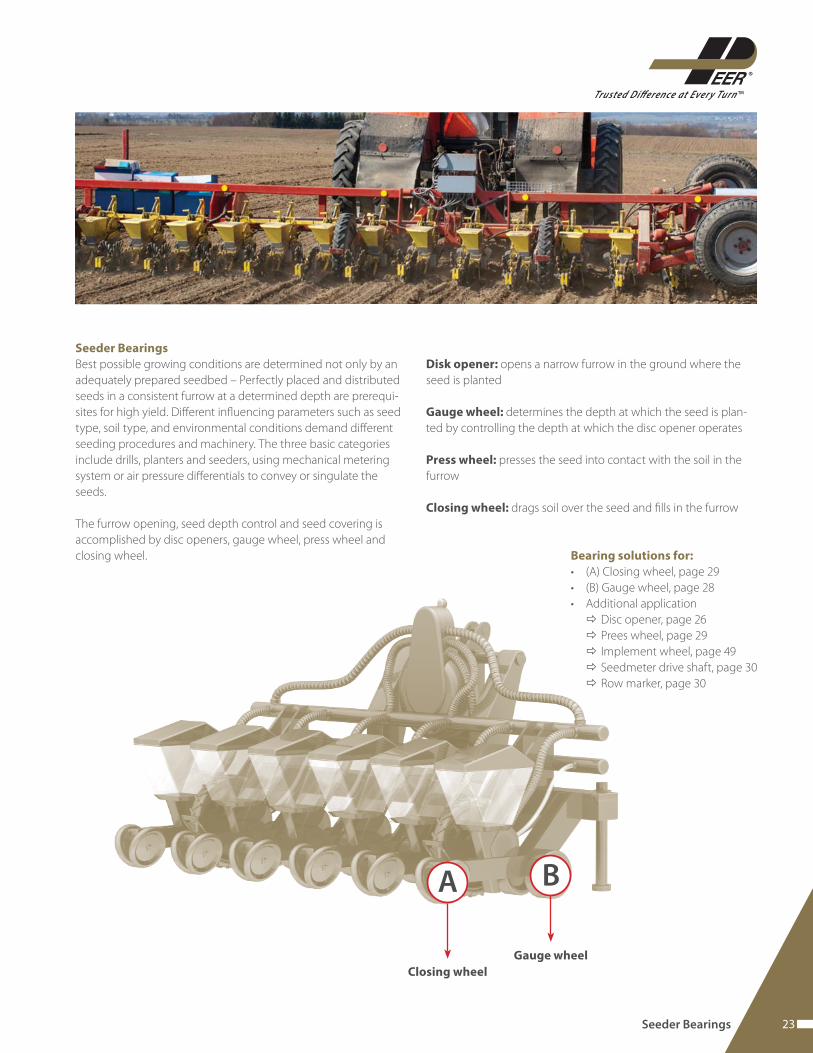
Seeder Bearings
Best possible growing conditions are determined not only by an
adequately prepared seedbed – Perfectly placed and distributed
seeds in a consistent furrow at a determined depth are prerequi-
sites for high yield. Diff erent infl uencing parameters such as seed
type, soil type, and environmental conditions demand diff erent
seeding procedures and machinery. The three basic categories
include drills, planters and seeders, using mechanical metering
system or air pressure diff erentials to convey or singulate the
seeds.
The furrow opening, seed depth control and seed covering is
accomplished by disc openers, gauge wheel, press wheel and
closing wheel.
Disk opener: opens a narrow furrow in the ground where the
seed is planted
Gauge wheel: determines the depth at which the seed is plan-
ted by controlling the depth at which the disc opener operates
Press wheel: presses the seed into contact with the soil in the
furrow
Closing wheel: drags soil over the seed and fi lls in the furrow
A
Bearing solutions for:
• (A) Closing wheel, page 29
• (B) Gauge wheel, page 28
• Additional application
Disc opener, page 26
Prees wheel, page 29
Implement wheel, page 49
Seedmeter drive shaft, page 30
Row marker, page 30
Closing wheel
B
Gauge wheel
Seeder Bearings
24 www.peerbearing.com
Drills
Seeding of multiple rows by row placement of seeds with a com-
mon seeder hopper and a volumetric displacement seeding me-
ter for all the seeding rows. The seeding units are each mounted
on a main frame and seed delivery is accomplished pneumatically
or by free seed fall through individual delivery tubes.
Planters
Seeding of multiple rows by multiple row seeding units, each ty-
pically containing a ground engaging tool, depth control compo-
nents and a singulating meter device for each row. Seeding units
are individually mounted on the main frame. The singulating and
conveying of seeds from the seed hopper takes place pneumati-
cally or by air pressure diff erential.
Seeders
Seeding by spreading or dropping the seed on the soil surface
without the use of furrow openers or seed covering devices un-
der the use of volumetric seed metering devices. Also a pneuma-
tically conveying of seeds to the ground openers of the seeding
tool or to spreaders at the front of the tillage tool might be used.
*Content derived from the American Society of Agricultural and
Biological Engineers (ASABE)
25
TMTrusted Difference at Ever y Turn
Seeder Bearings
Application challenges
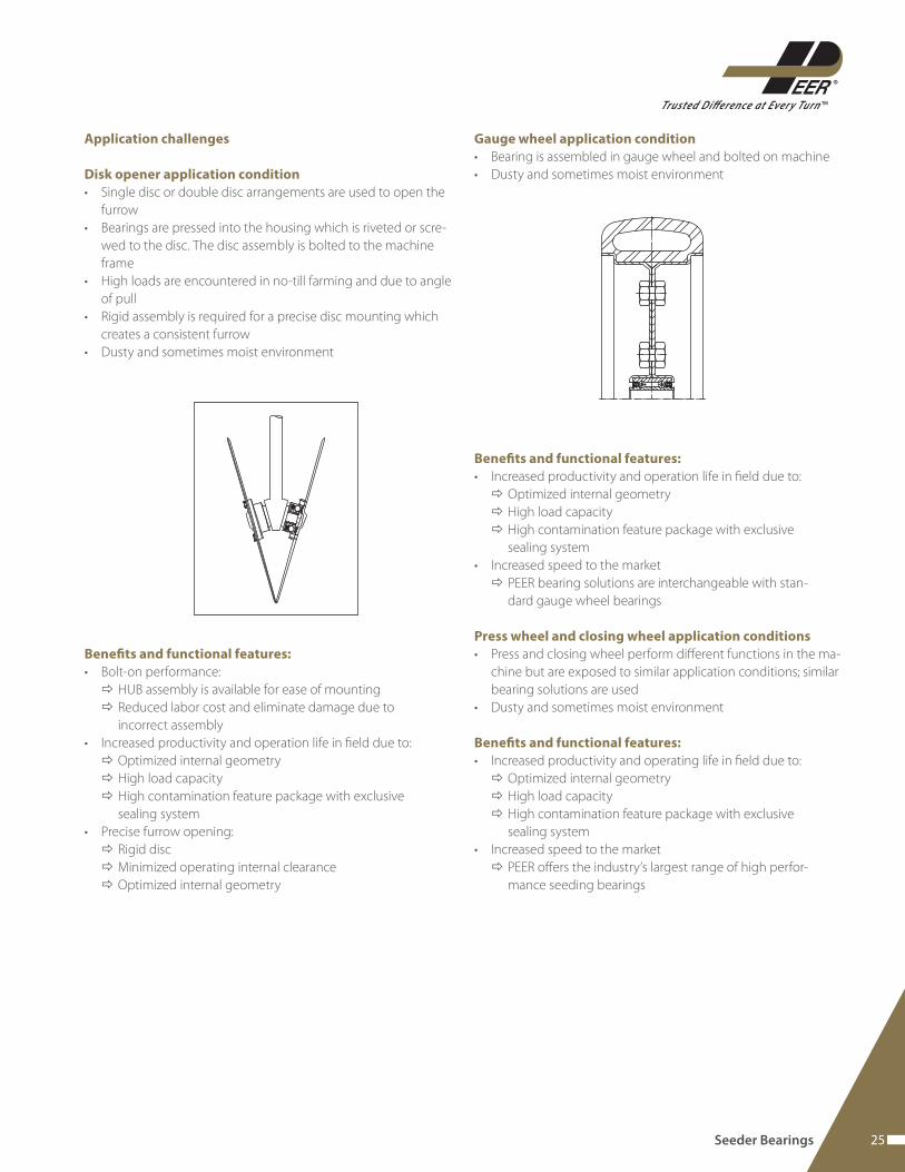
Disk opener application condition
• Single disc or double disc arrangements are used to open the
furrow
• Bearings are pressed into the housing which is riveted or scre-
wed to the disc. The disc assembly is bolted to the machine
frame
• High loads are encountered in no-till farming and due to angle
of pull
• Rigid assembly is required for a precise disc mounting which
creates a consistent furrow
• Dusty and sometimes moist environment
Benefi ts and functional features:
• Bolt-on performance:
HUB assembly is available for ease of mounting
Reduced labor cost and eliminate damage due to
incorrect assembly
• Increased productivity and operation life in fi eld due to:
Optimized internal geometry
High load capacity
High contamination feature package with exclusive
sealing system
• Precise furrow opening:
Rigid disc
Minimized operating internal clearance
Optimized internal geometry
Gauge wheel application condition
• Bearing is assembled in gauge wheel and bolted on machine
• Dusty and sometimes moist environment
Benefi ts and functional features:
• Increased productivity and operation life in fi eld due to:
Optimized internal geometry
High load capacity
High contamination feature package with exclusive
sealing system
• Increased speed to the market
PEER bearing solutions are interchangeable with stan-
dard gauge wheel bearings
Press wheel and closing wheel application conditions
• Press and closing wheel perform diff erent functions in the ma-
chine but are exposed to similar application conditions; similar
bearing solutions are used
• Dusty and sometimes moist environment
Benefi ts and functional features:
• Increased productivity and operating life in fi eld due to:
Optimized internal geometry
High load capacity
High contamination feature package with exclusive
sealing system
• Increased speed to the market
PEER off ers the industry’s largest range of high perfor-
mance seeding bearings
26 www.peerbearing.com
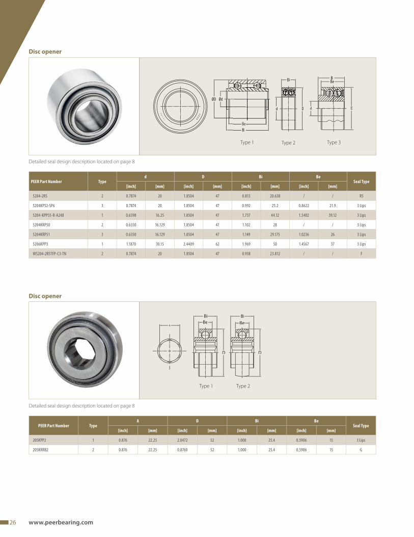
Detailed seal design description located on page 8
ØD Ød
Bi
D
Bi BiBe
Dd
Detailed seal design description located on page 8
Bi BiBe Be
D D
Type 1 Type 2
Disc opener
PEER Part Number TypeA D Bi Be
Seal Type[inch] [mm] [inch] [mm] [inch] [mm] [inch] [mm]
205KPP2 1 0.876 22.25 2.0472 52 1.000 25.4 0.5906 15 3 Lips
205KRRB2 2 0.876 22.25 0.8760 52 1.000 25.4 0.5906 15 G
Disc opener
Type 1 Type 2
PEER Part Number Typed D Bi Be
Seal Type[inch] [mm] [inch] [mm] [inch] [mm] [inch] [mm]
5204-2RS 2 0.7874 20 1.8504 47 0.813 20.638 / / RS
5204KP52-SP6 3 0.7874 20 1.8504 47 0.992 25.2 0.8622 21.9 3 Lips
5204-KPP55-R-A248 1 0.6398 16.25 1.8504 47 1.737 44.12 1.5402 39.12 3 Lips
5204KRP50 2 0.6350 16.129 1.8504 47 1.102 28 / / 3 Lips
5204KRP51 3 0.6350 16.129 1.8504 47 1.149 29.175 1.0236 26 3 Lips
5206KPP3 1 1.1870 30.15 2.4409 62 1.969 50 1.4567 37 3 Lips
W5204-2RSTFP-C3-TN 2 0.7874 20 1.8504 47 0.938 23.812 / / F
Type 3
27
TMTrusted Difference at Ever y Turn
Seeder Bearings
Detailed seal design description located on page 8
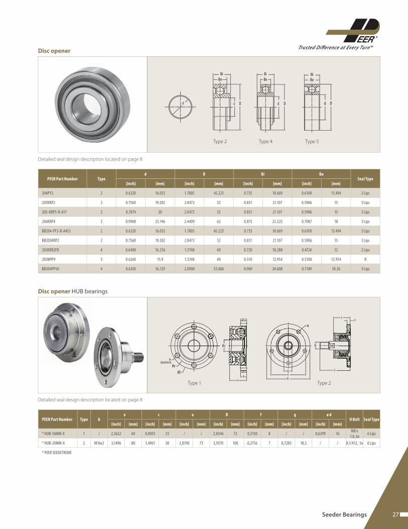
Disc opener
Detailed seal design description located on page 8
ffc
Øe
ØD
HEQUISPACED
a
bb
cf
H
geD
Type 1 Type 2
Disc opener HUB bearings
PEER Part Number Typed D Bi Be
Seal Type[inch] [mm] [inch] [mm] [inch] [mm] [inch] [mm]
204PY3 2 0.6320 16.053 1.7805 45.225 0.735 18.669 0.6100 15.494 2 Lips
205KRP2 2 0.7560 19.202 2.0472 52 0.831 21.107 0.5906 15 3 Lips
205-KRP5-R-A17 2 0.7874 20 2.0472 52 0.831 21.107 0.5906 15 3 Lips
206KRP4 2 0.9900 25.146 2.4409 62 0.875 22.225 0.7087 18 3 Lips
BB204-PF3-R-A453 2 0.6320 16.053 1.7805 45.225 0.735 18.669 0.6100 15.494 3 Lips
BB205KRP2 2 0.7560 19.202 2.0472 52 0.831 21.107 0.5906 15 3 Lips
203KRR2FD 4 0.6400 16.256 1.5748 40 0.720 18.288 0.4724 12 2 Lips
203NPP9 5 0.6260 15.9 1.5748 40 0.510 12.954 0.5100 12.954 R
BB304PP50 4 0.6350 16.129 2.0900 53.086 0.969 24.608 0.7189 18.26 3 Lips
PEER Part Number Type be c a D f g ø d
H Bolt Seal Type[inch] [mm] [inch] [mm] [inch] [mm] [inch] [mm] [inch] [mm] [inch] [mm] [inch] [mm]
* HUB-16MM-X 1 / 2,3622 60 0,9055 23 / / 2,8346 72 0,3150 8 / / 0,6299 16M8 x
1.0, 6x6 Lips
* HUB-20MM-X 2 M16x2 3,1496 80 1,4961 38 2,8740 73 3,9370 100 0,2756 7 0,7283 18,5 / / 8.5 H12, 5x 6 Lips
* PEER SEEDXTREME
d D
Bi
Be
d D
Bi
Be
dDd
Bi
Be
Type 2 Type 4 Type 5
28 www.peerbearing.com
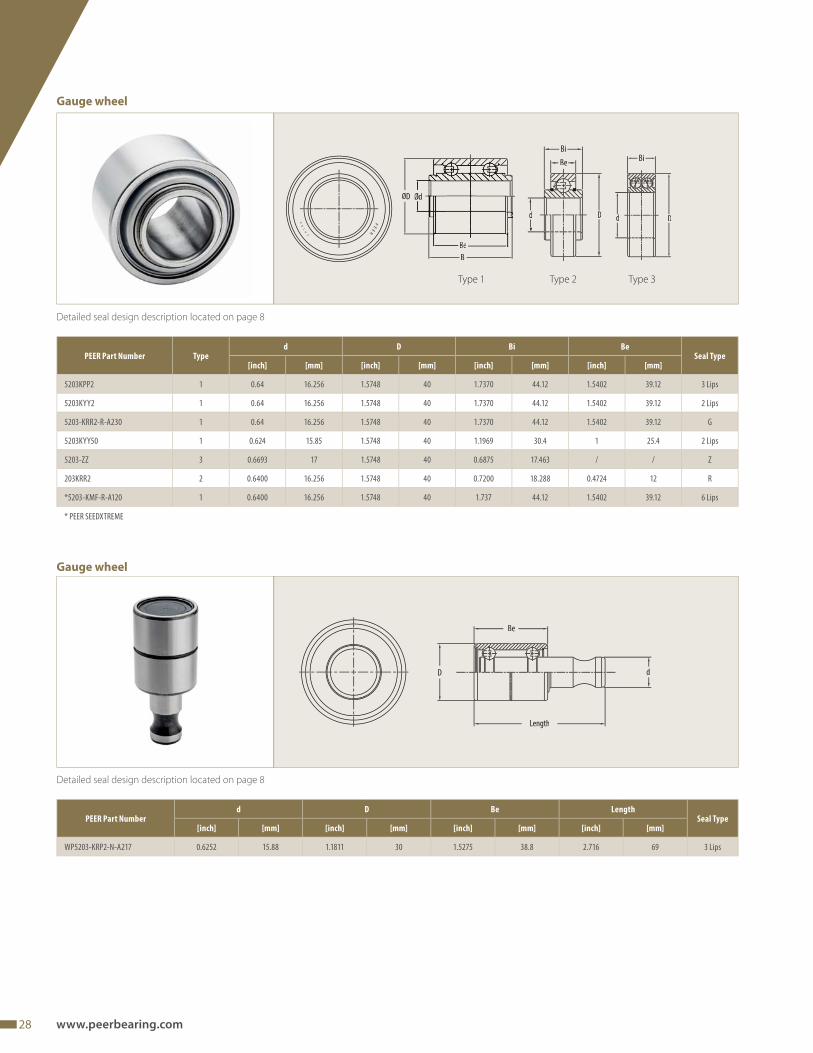
Detailed seal design description located on page 8
Detailed seal design description located on page 8
Be
D
Length
d
PEER Part Numberd D Be Length
Seal Type[inch] [mm] [inch] [mm] [inch] [mm] [inch] [mm]
WP5203-KRP2-N-A217 0.6252 15.88 1.1811 30 1.5275 38.8 2.716 69 3 Lips
ØD
Bi
dd D
Bi
BeBi
D
Type 1
Gauge wheel
Gauge wheel
Type 2 Type 3
PEER Part Number Typed D Bi Be
Seal Type[inch] [mm] [inch] [mm] [inch] [mm] [inch] [mm]
5203KPP2 1 0.64 16.256 1.5748 40 1.7370 44.12 1.5402 39.12 3 Lips
5203KYY2 1 0.64 16.256 1.5748 40 1.7370 44.12 1.5402 39.12 2 Lips
5203-KRR2-R-A230 1 0.64 16.256 1.5748 40 1.7370 44.12 1.5402 39.12 G
5203KYY50 1 0.624 15.85 1.5748 40 1.1969 30.4 1 25.4 2 Lips
5203-ZZ 3 0.6693 17 1.5748 40 0.6875 17.463 / / Z
203KRR2 2 0.6400 16.256 1.5748 40 0.7200 18.288 0.4724 12 R
*5203-KMF-R-A120 1 0.6400 16.256 1.5748 40 1.737 44.12 1.5402 39.12 6 Lips
* PEER SEEDXTREME
29
TMTrusted Difference at Ever y Turn
Seeder Bearings
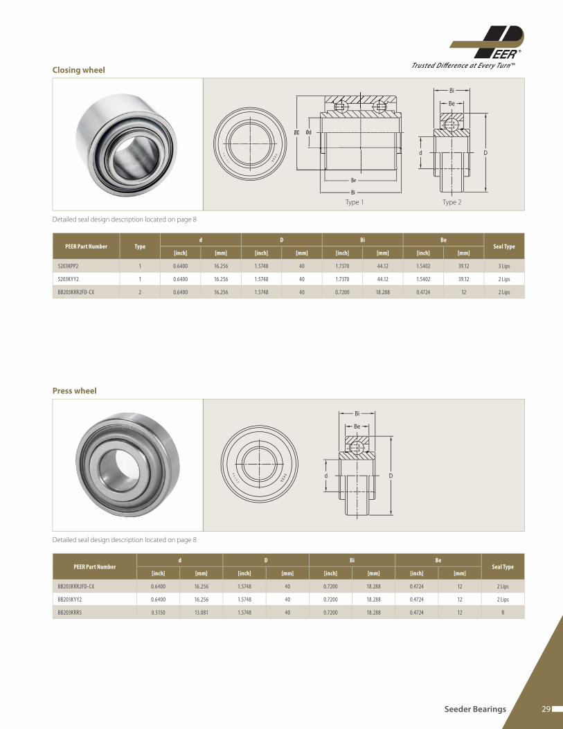
Detailed seal design description located on page 8
PEER Part Number Typed D Bi Be
Seal Type[inch] [mm] [inch] [mm] [inch] [mm] [inch] [mm]
5203KPP2 1 0.6400 16.256 1.5748 40 1.7370 44.12 1.5402 39.12 3 Lips
5203KYY2 1 0.6400 16.256 1.5748 40 1.7370 44.12 1.5402 39.12 2 Lips
BB203KRR2FD-CX 2 0.6400 16.256 1.5748 40 0.7200 18.288 0.4724 12 2 Lips
ØD Ød
Be
Bi
Type 1 Type 2
Closing wheel
Detailed seal design description located on page 8
PEER Part Numberd D Bi Be
Seal Type[inch] [mm] [inch] [mm] [inch] [mm] [inch] [mm]
BB203KRR2FD-CX 0.6400 16.256 1.5748 40 0.7200 18.288 0.4724 12 2 Lips
BB203KYY2 0.6400 16.256 1.5748 40 0.7200 18.288 0.4724 12 2 Lips
BB203KRR5 0.5150 13.081 1.5748 40 0.7200 18.288 0.4724 12 R
Press wheel
30 www.peerbearing.com
Detailed seal design description located on page 8
Detailed seal design description located on page 8
A
PEER Part NumberA D Bi Be
Seal Type[inch] [mm] [inch] [mm] [inch] [mm] [inch] [mm]
205KPPB54 0.8760 22.25 2.0472 52 0.903 22.936 0.5906 15 3 Lips
PEER Part Number TypeA d D Bi Be e s Length L2
Thread Seal Type[inch] [mm] [inch] [mm] [inch] [mm] [inch] [mm] [inch] [mm] [inch] [mm] [inch] [mm] [inch] [mm] [inch] [mm]
2BF205-7/8HX 1 0.876 22.25 / / 3.625 92.08 1 25.4 / / 2.25 57.15 0.4724 12 3.188 80.98 / / / 3 Lips
5203KYY50-ASSY 2 / / 0.6240 15.85 1.5748 40 1.1969 30.4 1 25.4 / / / / 4.291 109 2.677 68 M10X1.5-6H 2 Lips
Length
e
S
A
Length
Bi
Be
D d
Thread
L2
Type 1 Type 2
Seedmeter drive shaft
Seedmeter drive shaft
Detailed seal design description located on page 8
PEER Part
NumberType
d D Bi BeSeal Type
[inch] [mm] [mm] [inch] [mm] [inch] [mm] [inch]
206KRP4 2 0.9900 25.146 62 2.4409 22.23 0.8750 18 0.7087 3 Lips
5204KRP50 1 0.6350 16.129 47 1.8504 28.00 1.1024 / / 3 Lips
Be
Bi
D
d
B
Dd
Type 1
Row marker
Type 2
31
TMTrusted Difference at Ever y Turn
Combine Bearings
Combine Bearings
A combine harvester has the following main functional units:
• Header and feeder house: cutting of crops and transportation
into the threshing unit
• Threshing unit: threshing of crop in order to loosen the grain
from chaff and dust
• Shaker: separation of dust, straw, chaff and grain as well as
movement of straw towards the straw chopper or spreader
• Cleaning unit: cleaning of grain using air ventilation to achieve
clean grain
• Grain tank, auger: storage, transportation and unloading of
grain
• Straw chopper and straw spreader: chopping and spreading of
straw residue
After cutting and threshing, the desired crop is separated from
dust, chaff and straw. Optionally the straw is chopped and the
residue is left on fi eld.
Bearing solutions for:
• Auger bearings, page 33
• Feederhouse bearings, page 34
• Draper head bearings, page 34
• Corn head bearings, page 35
• Conveyor roller bearings, page 35
• Cleaning system shaker drive shaft bearings, page 36
• Clean grain elevator bearings, page 36
32 www.peerbearing.com
Application challenges
Common application conditions and environment
A combine has several diff erent bearing positions, each with
similar conditions but having unique challenges:
• Dry, dust-fi lled environment; several positions have direct crop
contact
• Medium to high speed (500 - 2000 min-1)
• Crop wrap and abrasive wear of bearing components
• Shock loads can be common
PEER proven engineering solutions
• Bolt-on performance
Full range of stamped steel and cast iron housings
Common use of set screws, eccentric lock collars or
hex bore bearings
• Increased productivity and bearing life in fi eld due to:
High contamination feature package with seals
matched to the application
• Increased speed to the market
PEER bearing solutions are interchangeable with
industry standard designs
PEER off ers one of the industry’s largest range of high
performance combine bearings
33
TMTrusted Difference at Ever y Turn
Combine Bearings
Detailed seal design description located on page 8
Tab 1
PEER Part Numberd D Bi Be L W
Seal Type[inch] [mm] [inch] [mm] [inch] [mm] [inch] [mm] [inch] [mm] [inch] [mm]
FH205-14-AP 0.8750 22.225 2.0472 52 0.8465 21.5 0.5906 15 1.22 31 1.5 38.1 F
FH205-16-AP 1.0000 25.4 2.0472 52 0.8465 21.5 0.5906 15 1.22 31 1.5 38.1 F
FH205-25MM-AP 0.9843 25 2.0472 52 0.8465 21.5 0.5906 15 1.22 31 1.5 38.1 F
FH206-18-AP 1.1250 28.575 2.4409 62 0.9370 23.8 0.7087 18 1.4055 35.7 1.7520 44.5 F
FH206-19-AP 1.1875 30.162 2.4409 62 0.9370 23.8 0.7087 18 1.4055 35.7 1.7520 44.5 F
FH206-20-AP 1.2500 31.75 2.4409 62 0.9370 23.8 0.7087 18 1.4055 35.7 1.7520 44.5 F
FH206-30MM-AP 1.1811 30 2.4409 62 0.9370 23.8 0.7087 18 1.4063 35.72 1.7520 44.5 F
FH207-20-AP 1.2500 31.75 2.8346 72 1.0000 25.4 0.7480 19 1.5315 38.9 2.1890 55.6 F
FH207-22-AP 1.3750 34.925 2.8346 72 1.0000 25.4 0.7480 19 1.5315 38.9 2.1890 55.6 F
FH207-23 1.4375 36.512 2.8346 72 1.0000 25.4 0.7480 19 1.5315 38.9 2.1890 55.6 F
FH207-35MM-AP 1.3780 35 2.8346 72 1.0000 25.4 0.7480 19 1.5315 38.9 2.1890 55.6 F
FH208-24-AP 1.5000 38.1 3.1496 80 1.1890 30.2 0.8661 22 1.7205 43.7 2.3740 60.3 F
FH208-40MM-AP 1.5748 40 3.1496 80 1.1890 30.2 0.8661 22 1.7205 43.7 2.3740 60.3 F
FH209-28-AP 1.7500 44.45 3.3465 85 1.1890 30.2 0.8661 22 1.7205 43.7 2.5000 63.5 F
FH209-45MM-AP 1.7717 45 3.3465 85 1.1890 30.2 0.8661 22 1.7205 43.7 2.5000 63.5 F
611
DD
W d
L
Bi
Be
L
Bi
W d
Auger
Tab 1 Tab 2
Tab 2
PEER Part Numberd D Bi Be L W
Seal Type[inch] [mm] [inch] [mm] [inch] [mm] [inch] [mm] [inch] [mm] [inch] [mm]
HC205-16-AP 1.0000 25.4 2.0472 52 1.3701 34.8 0.5906 15 1.7441 44.30 1.7520 44.50 *
HC206-19-GO-AP 1.1875 30.162 2.4409 62 1.4331 36.4 0.7087 18 1.9016 48.30 1.7520 44.50 *
HC206-20-AP 1.2500 31.75 2.4409 62 1.4331 36.4 0.7087 18 1.9016 48.30 1.7520 44.50 *
HC206-30MM-GO-AP 1.1811 30 2.4409 62 1.4331 36.4 0.7087 18 1.9016 48.30 1.7520 44.50 *
HC207-20-AP 1.2500 31.75 2.8346 72 1.4803 37.6 0.7480 19 2.0118 51.10 2.1890 55.60 *
HC207-22-AP 1.3750 34.925 2.8346 72 1.4803 37.6 0.7480 19 2.0118 51.10 2.1890 55.60 *
HC207-23 1.4375 36.513 2.8346 72 1.4803 37.6 0.7480 19 2.0118 51.10 2.1890 55.60 *
HC207-35MM-AP 1.3780 35 2.8346 72 1.4803 37.6 0.7480 19 2.0118 51.10 2.1890 55.60 *
HC208-24-AP 1.5000 38.1 3.1496 80 1.6850 42.8 0.8661 22 2.2200 56.30 2.3740 60.30 *
HC208-40MM-AP 1.5748 40 3.1496 80 1.6850 42.8 0.8661 22 2.2165 56.30 2.3740 60.30 *
HC209-26-GO-AP 1.6250 41.275 3.3465 85 1.6850 42.8 0.8661 22 2.2165 56.30 2.5000 63.50 *
HC209-28-AP 1.7500 44.45 3.3465 85 1.6850 42.8 0.8661 22 2.2165 56.30 2.5000 63.50 *
*single lip or triple lips can be used
34 www.peerbearing.com
Detailed seal design description located on page 8
PEER Part Number TypeA D Bi Be
Seal Type[inch] [mm] [inch] [mm] [inch] [mm] [inch] [mm]
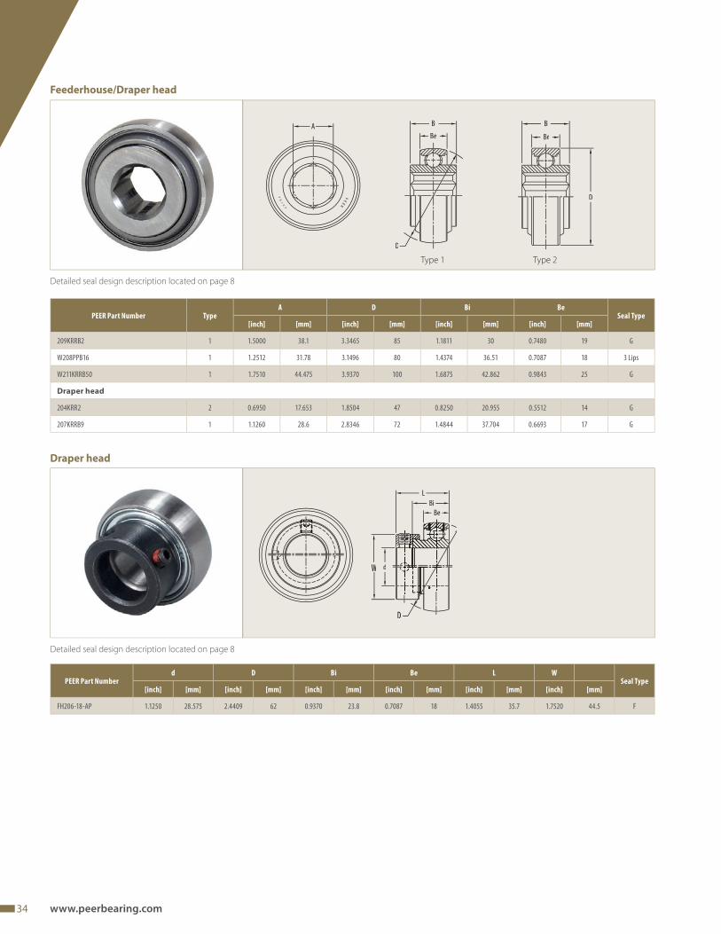
209KRRB2 1 1.5000 38.1 3.3465 85 1.1811 30 0.7480 19 G
W208PPB16 1 1.2512 31.78 3.1496 80 1.4374 36.51 0.7087 18 3 Lips
W211KRRB50 1 1.7510 44.475 3.9370 100 1.6875 42.862 0.9843 25 G
Draper head
204KRR2 2 0.6950 17.653 1.8504 47 0.8250 20.955 0.5512 14 G
207KRRB9 1 1.1260 28.6 2.8346 72 1.4844 37.704 0.6693 17 G
Detailed seal design description located on page 8
A Bi Bi
Be Be
D
D
Type 1 Type 2
Feederhouse/Draper head
Draper head
PEER Part Numberd D Bi Be L W
Seal Type[inch] [mm] [inch] [mm] [inch] [mm] [inch] [mm] [inch] [mm] [inch] [mm]
FH206-18-AP 1.1250 28.575 2.4409 62 0.9370 23.8 0.7087 18 1.4055 35.7 1.7520 44.5 F
D
W d
L
Bi
Be
35
TMTrusted Difference at Ever y Turn
PEER Part Number TypeA/d D Bi Be
Seal Type[inch] [mm] [inch] [mm] [inch] [mm] [inch] [mm]
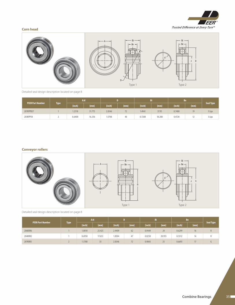
207KPPB57 1 1.2510 31.775 2.8346 72 1.4941 37.95 0.7480 19 3 Lips
203KPP50 2 0.6400 16.256 1.5748 40 0.7200 18.288 0.4724 12 3 Lips
Detailed seal design description located on page 8
A Bi
Be
D
d
D
Bi
Be
d
Type 1 Type 2
Detailed seal design description located on page 8
PEER Part Number TypeA/d D Bi Be
Seal Type[inch] [mm] [inch] [mm] [inch] [mm] [inch] [mm]
206KRR6 1 1.0010 25.425 2.4409 62 0.9449 24 0.6299 16 R
204KRR2 1 0.6950 17.653 1.8504 47 0.8250 20.955 0.5512 14 R
207KRR3 2 1.3780 35 2.8346 72 0.9843 25 0.6693 17 G
Corn head
Conveyor rollers
Combine Bearings
d
D
Bi
Be
d
Bi
Be
D
A
Type 1 Type 2
36 www.peerbearing.com
PEER Part NumberA D Bi Be
Seal Type[inch] [mm] [inch] [mm] [inch] [mm] [inch] [mm]
205KPPB2 0.8760 22.25 2.0472 52 1.0000 25.4 0.5906 15 3 Lips
208KPPB52 1.1260 28.6 3.1496 80 1.1024 28 0.7087 18 3 Lips
Detailed seal design description located on page 8
Detailed seal design description located on page 8
242424
L
Bi
DdW
A
Detailed seal design description located on page 8
PEER Part Numberd D Bi Be L W
Seal Type[inch] [mm] [inch] [mm] [inch] [mm] [inch] [mm] [inch] [mm] [inch] [mm]
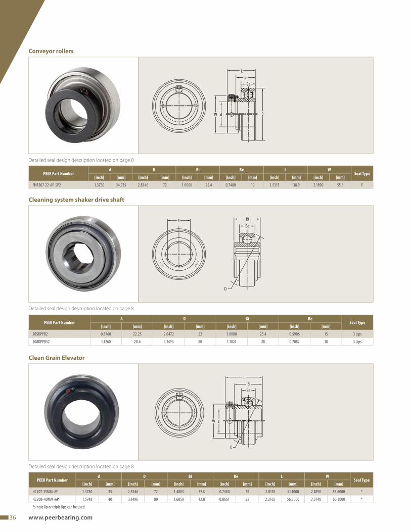
HC207-35MM-AP 1.3780 35 2.8346 72 1.4803 37.6 0.7480 19 2.0118 51.1000 2.1890 55.6000 *
HC208-40MM-AP 1.5748 40 3.1496 80 1.6850 42.8 0.8661 22 2.2165 56.3000 2.3740 60.3000 *
*single lip or triple lips can be used
00022--
666000
22
L
Bi
Be
W d
D
Conveyor rollers
Cleaning system shaker drive shaft
Clean Grain Elevator
PEER Part Numberd D Bi Be L W
Seal Type[inch] [mm] [inch] [mm] [inch] [mm] [inch] [mm] [inch] [mm] [inch] [mm]
FHR207-22-AP-SP2 1.3750 34.925 2.8346 72 1.0000 25.4 0.7480 19 1.5315 38.9 2.1890 55.6 F
37
TMTrusted Difference at Ever y Turn
Baler Bearings
Baler Bearings
To harvest fodder, (such as tall grasses and legumes) or plant
residue (such as corn stalks, wheat straw or peanut vines) crops
are fi rst cut, dried to specifi c moisture content, and formed into
a windrow. Then balers pick up and compact the crop to form
round or square bales for ease of transport and storage.
The more recent practice of baling corn stalks and peanut vines
creates extra stress on the internal components of balers and
special, heavy duty bearing designs have been created to provide
the expected reliability to accommodate this practice.
Round balers use belts or chains to roll crop into round bales
and can have either variable or fi xed chambers. Inside the baling
chamber it is formed and compressed and discharged on the
fi eld afterwards to be collected and stored.
Square balers form the crop residue in square bales: augers feed
the straw into the baling chamber for compression. Plungers give
the bale the density and shape - when the appropriate length
and shape of the bale is reached, the bale is tied and exits the
chamber.
Typical weight of bale:
• 635 Kg / 1400 lbs large (square bale)
• 20 - 40 Kg / 50 – 100 lbs small (square bale)
Bearing solutions for:
• Pickup tine bar, page 45
• Pickup cam follower, page 44
Additional applications:
• Roller bearings
Drive roll, page 42
Idler roll, page 40
• Implement wheel, page 49
A
38 www.peerbearing.com
Application challenges
The baler has several diff erent bearing positions, each with similar
conditions but having unique challenges. In a high level, it can be
broken up into the following sections:
• Pickup
• Bale chamber
Load and contamination typically contribute to bearing damage.
Pickup assembly application condition
The pickup assembly rakes the hay from the windrow into the
baling chamber. Tine bar, pickup drum and cam follower are all
part of the pickup subassembly.
• The tine bar is a bar of tine that rakes the hay off the fi eld and
into the baling chamber
• The cam follower creates a fl ipping action to the tine bar to
deposit the hay into the baling chamber
Tine bar application condition
• Four to six tine bars on a reel with two bearings supporting
each tine bar
• Exposed to oscillating motion from the pickup cam follower
• Medium to high contamination due to dry and wrapping hay
and contact with soil
Proven engineered solutions:
Tine bar bearings
Benefi ts and functional features:
• Increased productivity and operating life in fi eld due to:
High contamination feature package with exclusive
sealing system
• Bolt-on performance:
For ease of mounting an extended inner ring with
through hole for roll-pin
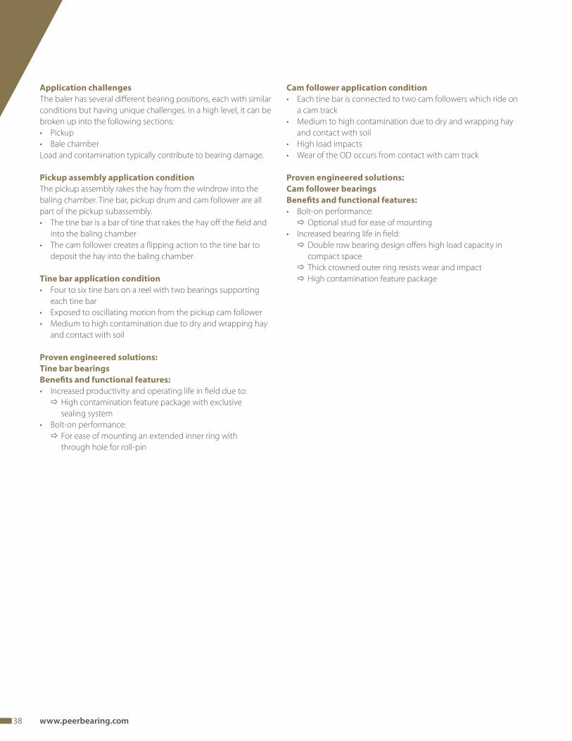
Cam follower application condition
• Each tine bar is connected to two cam followers which ride on
a cam track
• Medium to high contamination due to dry and wrapping hay
and contact with soil
• High load impacts
• Wear of the OD occurs from contact with cam track
Proven engineered solutions:
Cam follower bearings
Benefi ts and functional features:
• Bolt-on performance:
Optional stud for ease of mounting
• Increased bearing life in fi eld:
Double row bearing design off ers high load capacity in
compact space
Thick crowned outer ring resists wear and impact
High contamination feature package
39
TMTrusted Difference at Ever y Turn
Bale chamber application condition
Idler roll bearings support and establish the belt tension.
Drive rolls rotate belts at appropriate speed. Both rollers are most-
ly exposed to the following application conditions:
Idler and driver roller application conditions
• Two bearings support the roll which spans the width of the
bale chamber
• Rolls can either be chain-driven or non-chain-driven with
driven rolls typically using larger bearings
• Support bearings placed outside the chamber are exposed to
medium contamination
• Support bearings placed inside the chamber are exposed to
high contamination
• Loading at the end of a baling cycle combined with shaft
defl ection can generate severe stress on the internal compo-
nents of the support bearings
Proven engineered solutions:
Idler, drive roll bearings
Benefi ts and functional features:
• Bolt on performance
Several mounting and housing options available
• Increased bearing life in fi eld:
Application specifi c internal construction accommo-
dates shaft defl ection
High contamination feature package with exclusive
sealing system
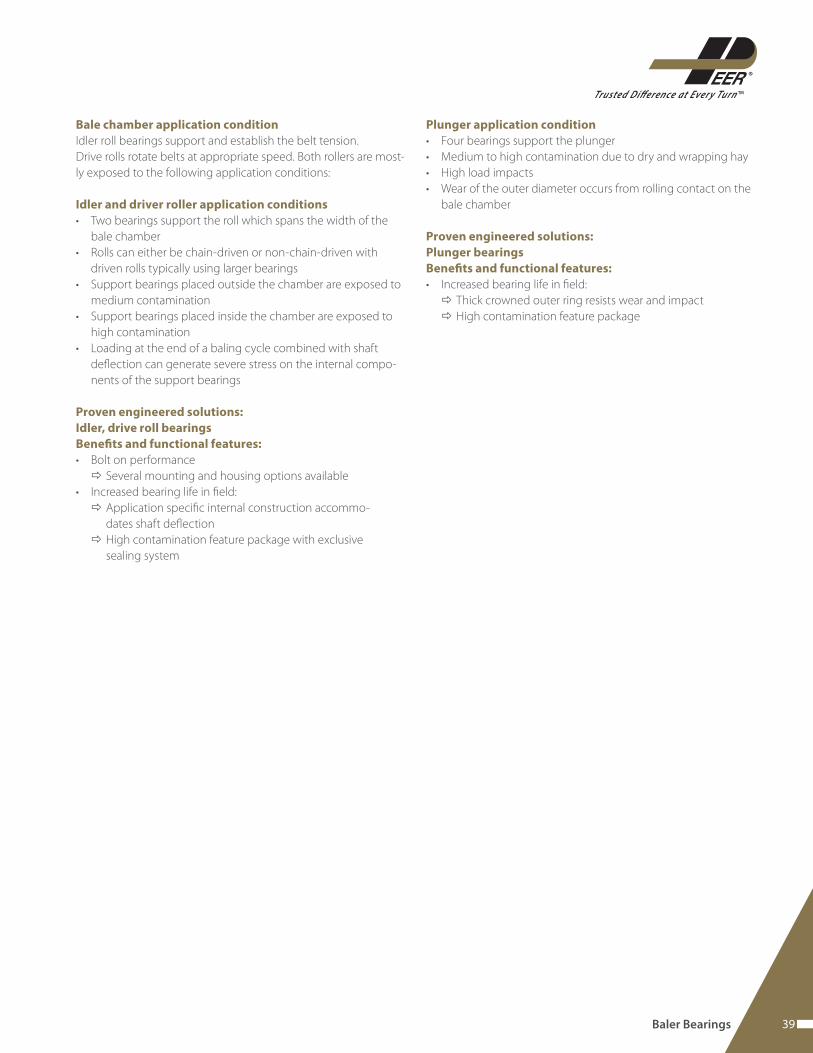
Plunger application condition
• Four bearings support the plunger
• Medium to high contamination due to dry and wrapping hay
• High load impacts
• Wear of the outer diameter occurs from rolling contact on the
bale chamber
Proven engineered solutions:
Plunger bearings
Benefi ts and functional features:
• Increased bearing life in fi eld:
Thick crowned outer ring resists wear and impact
High contamination feature package
Baler Bearings
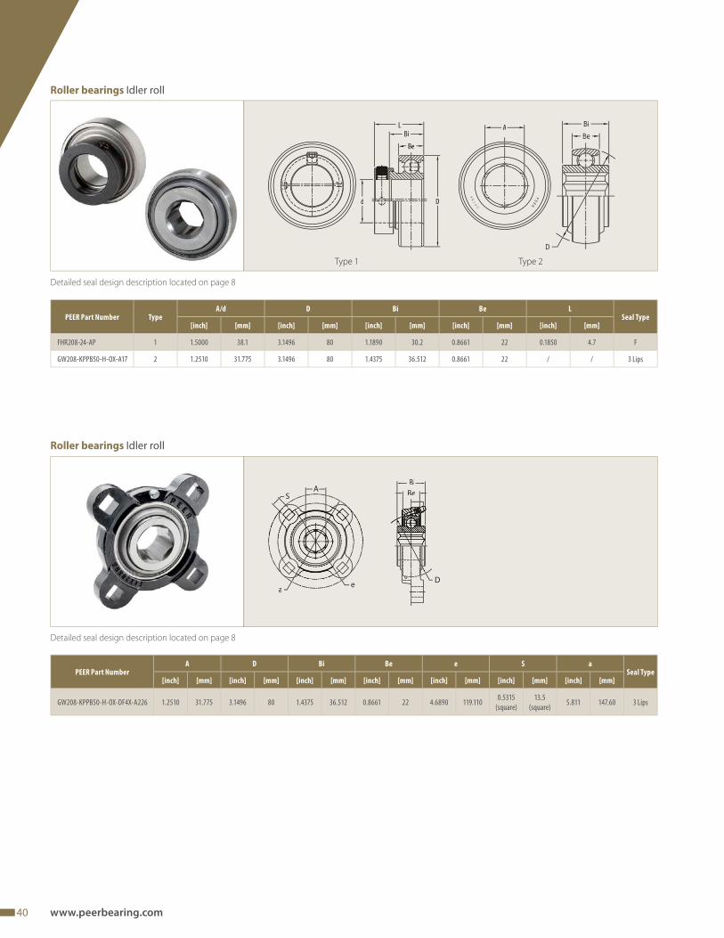
40 www.peerbearing.com
PEER Part Number TypeA/d D Bi Be L
Seal Type[inch] [mm] [inch] [mm] [inch] [mm] [inch] [mm] [inch] [mm]
FHR208-24-AP 1 1.5000 38.1 3.1496 80 1.1890 30.2 0.8661 22 0.1850 4.7 F
GW208-KPPB50-H-OX-A17 2 1.2510 31.775 3.1496 80 1.4375 36.512 0.8661 22 / / 3 Lips
Detailed seal design description located on page 8
PEER Part NumberA D Bi Be e S a
Seal Type[inch] [mm] [inch] [mm] [inch] [mm] [inch] [mm] [inch] [mm] [inch] [mm] [inch] [mm]
GW208-KPPB50-H-OX-DF4X-A226 1.2510 31.775 3.1496 80 1.4375 36.512 0.8661 22 4.6890 119.1100.5315
(square)
13.5
(square)5.811 147.60 3 Lips
d D
LBi
242424
A
Type 1
Detailed seal design description located on page 8
D
BiBeA
S
ea
Type 2
Roller bearings Idler roll
Roller bearings Idler roll
41
TMTrusted Difference at Ever y Turn
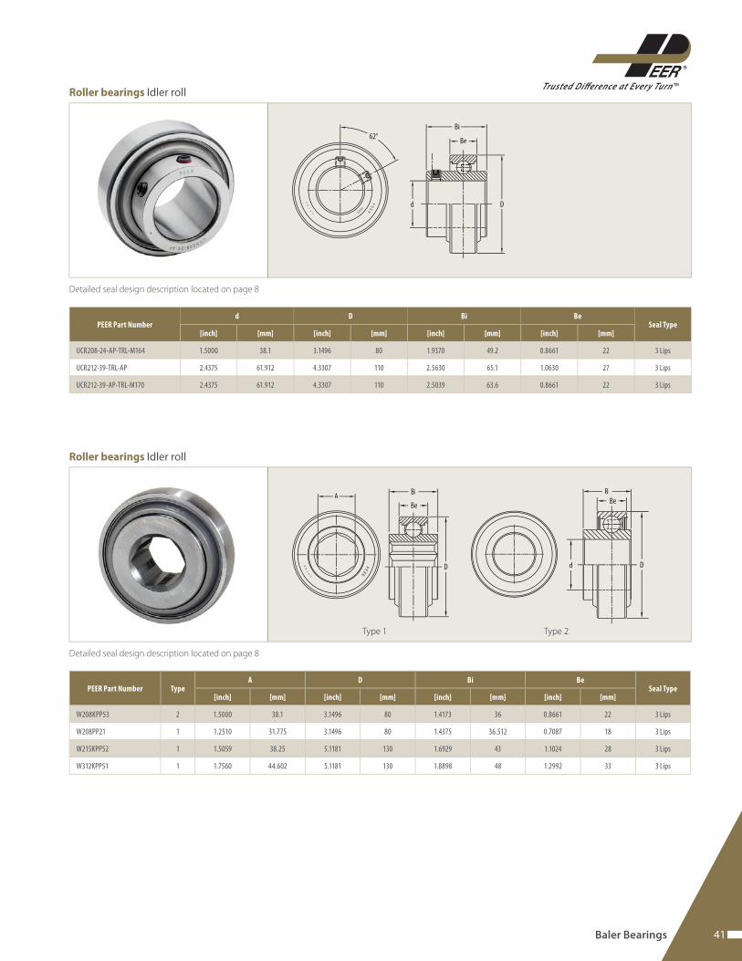
Baler Bearings
PEER Part Numberd D Bi Be
Seal Type[inch] [mm] [inch] [mm] [inch] [mm] [inch] [mm]
UCR208-24-AP-TRL-M164 1.5000 38.1 3.1496 80 1.9370 49.2 0.8661 22 3 Lips
UCR212-39-TRL-AP 2.4375 61.912 4.3307 110 2.5630 65.1 1.0630 27 3 Lips
UCR212-39-AP-TRL-M170 2.4375 61.912 4.3307 110 2.5039 63.6 0.8661 22 3 Lips
Detailed seal design description located on page 8
Bi
Be
Dd
62°
Detailed seal design description located on page 8
ABe
BiBe
Bi
d DD
Roller bearings Idler roll
Roller bearings Idler roll
Type 1 Type 2
PEER Part Number TypeA D Bi Be
Seal Type[inch] [mm] [inch] [mm] [inch] [mm] [inch] [mm]
W208KPP53 2 1.5000 38.1 3.1496 80 1.4173 36 0.8661 22 3 Lips
W208PP21 1 1.2510 31.775 3.1496 80 1.4375 36.512 0.7087 18 3 Lips
W215KPP52 1 1.5059 38.25 5.1181 130 1.6929 43 1.1024 28 3 Lips
W312KPP51 1 1.7560 44.602 5.1181 130 1.8898 48 1.2992 33 3 Lips
42 www.peerbearing.com
PEER Part NumberA D Bi Be
Seal Type[inch] [mm] [inch] [mm] [inch] [mm] [inch] [mm]
210RRB52-SP1 1.5000 38.1 3.6024 91.5 1.1811 30 0.8661 22 G
Detailed seal design description located on page 8
A
Detailed seal design description located on page 8
PEER Part Number TypeA D Bi Be e S a
Seal Type[inch] [mm] [inch] [mm] [inch] [mm] [inch] [mm] [inch] [mm] [inch] [mm] [inch] [mm]
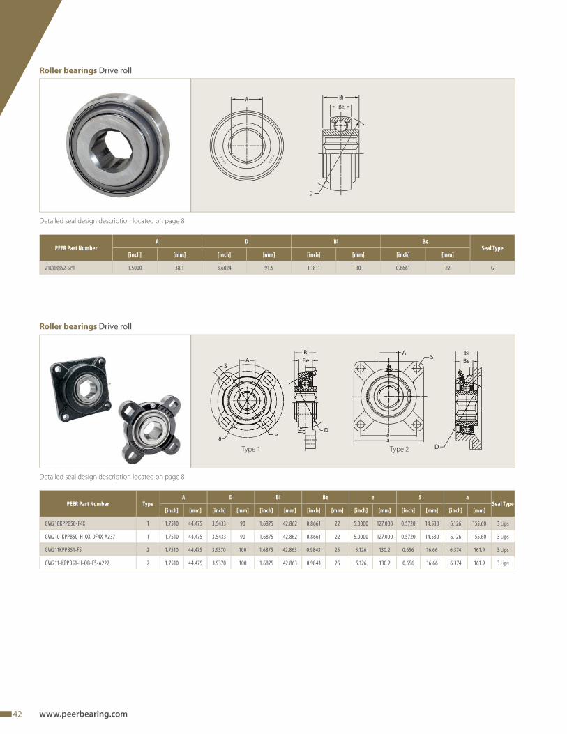
GW210KPPB50-F4X 1 1.7510 44.475 3.5433 90 1.6875 42.862 0.8661 22 5.0000 127.000 0.5720 14.530 6.126 155.60 3 Lips
GW210-KPPB50-H-OX-DF4X-A237 1 1.7510 44.475 3.5433 90 1.6875 42.862 0.8661 22 5.0000 127.000 0.5720 14.530 6.126 155.60 3 Lips
GW211KPPB51-FS 2 1.7510 44.475 3.9370 100 1.6875 42.863 0.9843 25 5.126 130.2 0.656 16.66 6.374 161.9 3 Lips
GW211-KPPB51-H-OB-FS-A222 2 1.7510 44.475 3.9370 100 1.6875 42.863 0.9843 25 5.126 130.2 0.656 16.66 6.374 161.9 3 Lips
D
BiBe
S
ea
BiBe
Dea
SA
Type 1 Type 2
Roller bearings Drive roll
Roller bearings Drive roll
43
TMTrusted Difference at Ever y Turn
Detailed seal design description located on page 8
Bi
D
Bee
a
S
HeightSquare
Detailed seal design description located on page 8
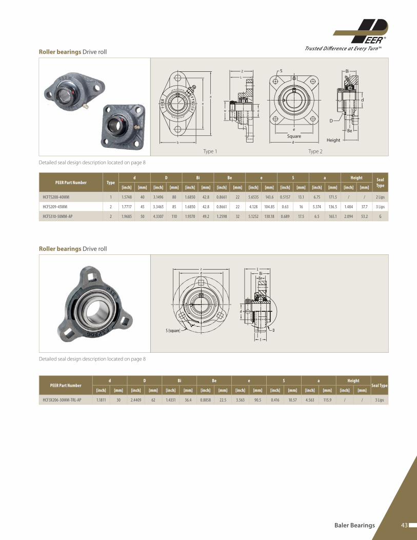
PEER Part Number Typed D Bi Be e S a Height Seal
Type[inch] [mm] [inch] [mm] [inch] [mm] [inch] [mm] [inch] [mm] [inch] [mm] [inch] [mm] [inch] [mm]
HCFTS208-40MM 1 1.5748 40 3.1496 80 1.6850 42.8 0.8661 22 5.6535 143.6 0.5157 13.1 6.75 171.5 / / 2 Lips
HCFS209-45MM 2 1.7717 45 3.3465 85 1.6850 42.8 0.8661 22 4.128 104.85 0.63 16 5.374 136.5 1.484 37.7 3 Lips
HCFS310-50MM-AP 2 1.9685 50 4.3307 110 1.9370 49.2 1.2598 32 5.1252 130.18 0.689 17.5 6.5 165.1 2.094 53.2 G
Type 1 Type 2
Roller bearings Drive roll
Roller bearings Drive roll
Baler Bearings
000333MMMMMMM
L
d
BiBe
D
I
S (square)
ae
PEER Part Numberd D Bi Be e S a Height
Seal Type[inch] [mm] [inch] [mm] [inch] [mm] [inch] [mm] [inch] [mm] [inch] [mm] [inch] [mm] [inch] [mm]
HCF3X206-30MM-TRL-AP 1.1811 30 2.4409 62 1.4331 36.4 0.8858 22.5 3.563 90.5 0.416 10.57 4.563 115.9 / / 3 Lips
44 www.peerbearing.com
Detailed seal design description located on page 8
D d
Bi
Be
D
d
Bi
Be
Detailed seal design description located on page 8
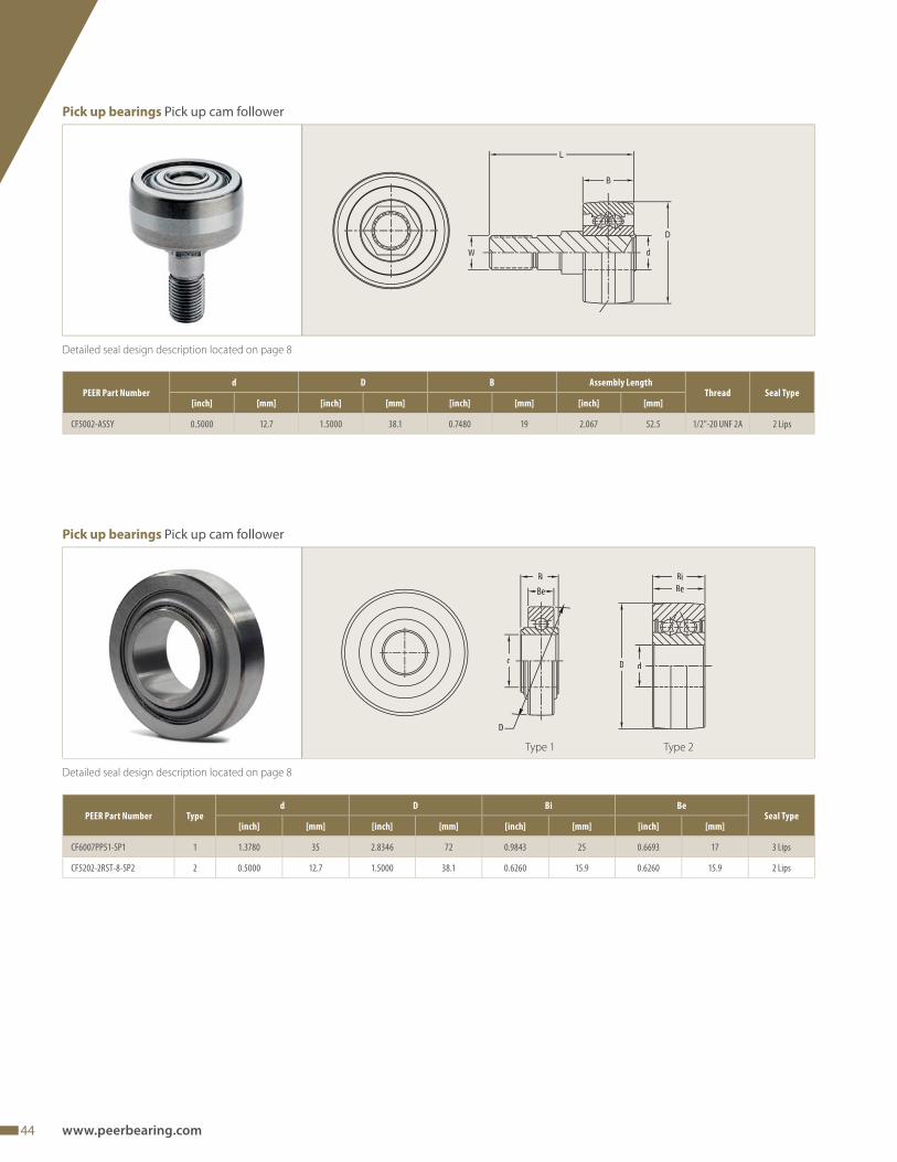
PEER Part Numberd D B Assembly Length
Thread Seal Type[inch] [mm] [inch] [mm] [inch] [mm] [inch] [mm]
CF5002-ASSY 0.5000 12.7 1.5000 38.1 0.7480 19 2.067 52.5 1/2"-20 UNF 2A 2 Lips
Pick up bearings Pick up cam follower
Pick up bearings Pick up cam follower
Type 1 Type 2
PEER Part Number Typed D Bi Be
Seal Type[inch] [mm] [inch] [mm] [inch] [mm] [inch] [mm]
CF6007PP51-SP1 1 1.3780 35 2.8346 72 0.9843 25 0.6693 17 3 Lips
CF5202-2RST-8-SP2 2 0.5000 12.7 1.5000 38.1 0.6260 15.9 0.6260 15.9 2 Lips
45
TMTrusted Difference at Ever y Turn
Baler Bearings
Detailed seal design description located on page 8
Detailed seal design description located on page 8
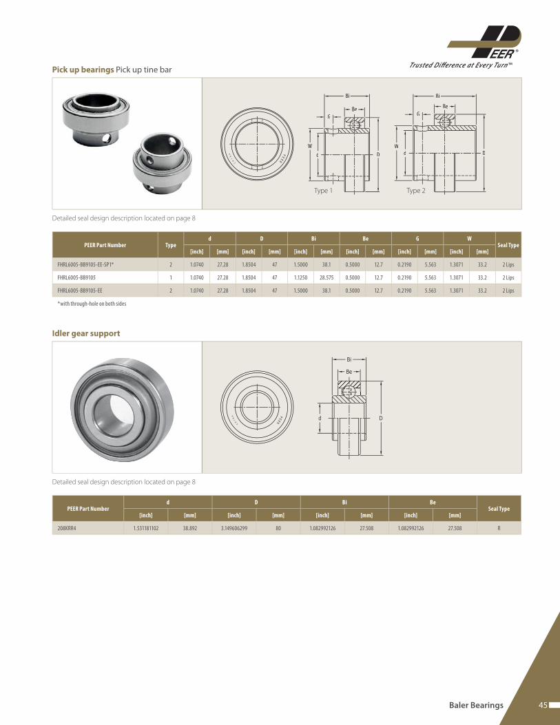
PEER Part Number Typed D Bi Be G W
Seal Type[inch] [mm] [inch] [mm] [inch] [mm] [inch] [mm] [inch] [mm] [inch] [mm]
FHRL6005-BB9105-EE-SP1* 2 1.0740 27.28 1.8504 47 1.5000 38.1 0.5000 12.7 0.2190 5.563 1.3071 33.2 2 Lips
FHRL6005-BB9105 1 1.0740 27.28 1.8504 47 1.1250 28.575 0.5000 12.7 0.2190 5.563 1.3071 33.2 2 Lips
FHRL6005-BB9105-EE 2 1.0740 27.28 1.8504 47 1.5000 38.1 0.5000 12.7 0.2190 5.563 1.3071 33.2 2 Lips
*with through-hole on both sides
Bi
Be
Dd d D
Be
Bi
WW
GG
Type 1 Type 2
Pick up bearings Pick up tine bar
Idler gear support
PEER Part Numberd D Bi Be
Seal Type[inch] [mm] [inch] [mm] [inch] [mm] [inch] [mm]
208KRR4 1.531181102 38.892 3.149606299 80 1.082992126 27.508 1.082992126 27.508 R
46 www.peerbearing.com
Detailed seal design description located on page 8
A
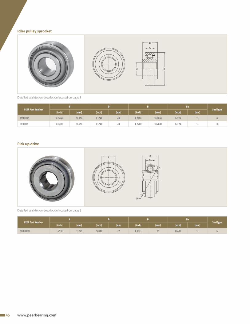
PEER Part NumberA D Bi Be
Seal Type[inch] [mm] [inch] [mm] [inch] [mm] [inch] [mm]
207KRRB17 1.2510 31.775 2.8346 72 0.9843 25 0.6693 17 G
Pick up drive
Detailed seal design description located on page 8
PEER Part Numberd D Bi Be
Seal Type[inch] [mm] [inch] [mm] [inch] [mm] [inch] [mm]
203KRR50 0.6400 16.256 1.5748 40 0.7200 18.2880 0.4724 12 G
203KRR2 0.6400 16.256 1.5748 40 0.7200 18.2880 0.4724 12 R
Idler pulley sprocket
47
TMTrusted Difference at Ever y Turn
Detailed seal design description located on page 8
d Dd
D
BiBe
BiBe
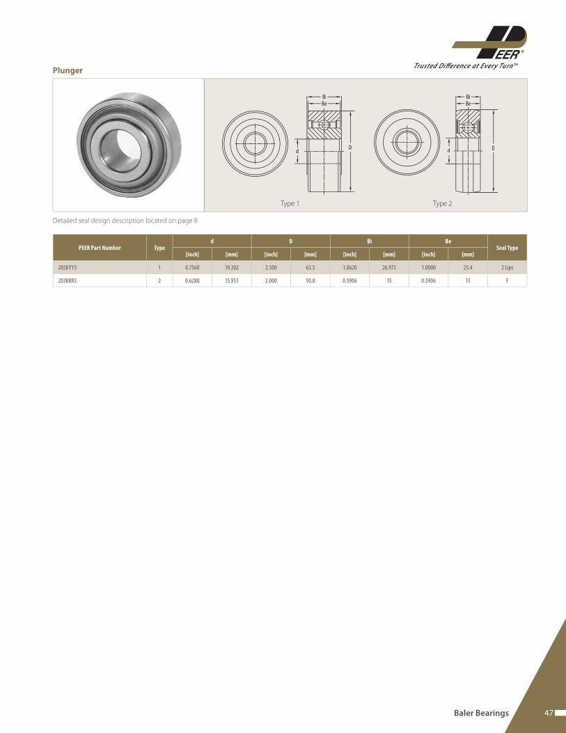
Plunger
Baler Bearings
Type 1 Type 2
PEER Part Number Typed D Bi Be
Seal Type[inch] [mm] [inch] [mm] [inch] [mm] [inch] [mm]
205KYY3 1 0.7560 19.202 2.500 63.5 1.0620 26.975 1.0000 25.4 2 Lips
203KRR3 2 0.6280 15.951 2.000 50.8 0.5906 15 0.5906 15 F
48 www.peerbearing.com
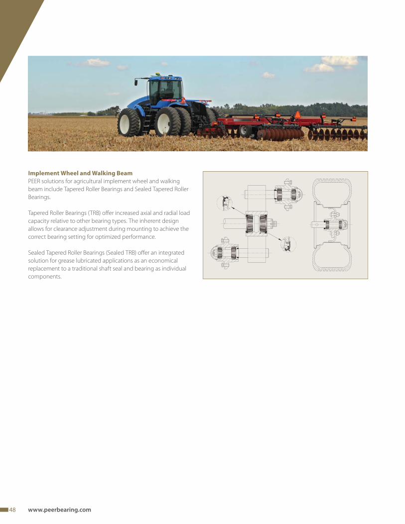
Implement Wheel and Walking Beam
PEER solutions for agricultural implement wheel and walking
beam include Tapered Roller Bearings and Sealed Tapered Roller
Bearings.
Tapered Roller Bearings (TRB) off er increased axial and radial load
capacity relative to other bearing types. The inherent design
allows for clearance adjustment during mounting to achieve the
correct bearing setting for optimized performance.
Sealed Tapered Roller Bearings (Sealed TRB) off er an integrated
solution for grease lubricated applications as an economical
replacement to a traditional shaft seal and bearing as individual
components.
49
TMTrusted Difference at Ever y Turn
D d
C
B
T
PEER Part NumberCONE CUP
T (mm)d (mm) B (mm) D (mm) C (mm)
460 / 453A 44.45 29.317 107.95 22.225 27.783
2790 / 2720 33.338 25.654 76.2 19.05 23.774
3780 / 3720 50.8 30.302 93.264 23.812 30.162
15123 / 15250 31.75 19.05 63.5 15.875 19.478
15126 / 15250 31.75 20.638 63.5 15.875 20.638
25580 / 25520 44.45 25.4 82.931 19.05 23.812
25590 / 25520 45.618 25.4 82.931 19.05 23.812
25877 / 25821 34.925 24.608 73.025 19.05 23.812
30207 35 17 72 15 18.25
33109 45 26 80 20.5 26
33889 / 33821 50.8 28.575 95.25 22.225 27.783
39585 / 39520 63.500 30.162 112.712 23.812 30.162
45289/ 45220 57.15 30.958 104.775 23.812 30.162
342A-d2 / 332 41.275 29.977 80 17.826 28.575
387AS / 382A 57.15 21.946 96.838 15.875 21
HM212049 / HM212011 66.675 38.354 122.238 29.718 38.1
HM218248 / HM218210 89.974 40 146.975 32.5 40
HM803149 / HM803110 44.45 29.37 88.9 23.02 30.162
JL69349 / JL69310 38 17 62 13.5 17
JLM506849 / JLM506810 55 23 90 18.5 23
L44643 / L44610 25.4 14.732 50.292 10.668 14.224
L44649 / L44610 26.988 14.732 50.292 10.668 14.224
L68149 / L68111 34.988 16.764 59.975 11.938 15.875
LM104949 / LM104911 50.8 22.225 82.55 16.51 21.59
LM29749 / LM29710 38.1 18.288 65.088 13.97 18.034
LM48548 / LM48510 34.925 18.288 65.088 13.97 18.034
LM501349 / LM501310 41.275 19.812 73.431 14.732 19.558
LM603049 / LM603011 45.242 19.842 77.788 15.08 19.842
LM67048 / LM67010 31.75 16.764 59.131 11.811 15.875
Implement wheel and walking beam
50 www.peerbearing.com
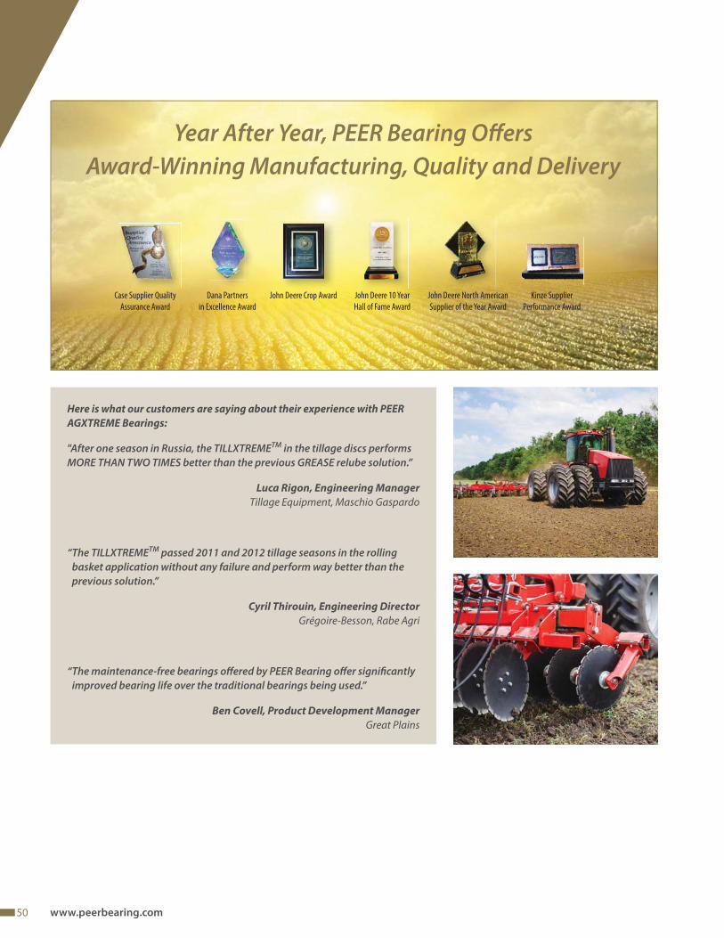
Here is what our customers are saying about their experience with PEER
AGXTREME Bearings:
"After one season in Russia, the TILLXTREMETM in the tillage discs performs MORE THAN TWO TIMES better than the previous GREASE relube solution.”
Luca Rigon, Engineering Manager
Tillage Equipment, Maschio Gaspardo
“ The TILLXTREMETM passed 2011 and 2012 tillage seasons in the rolling basket application without any failure and perform way better than the previous solution.”
Cyril Thirouin, Engineering Director
Grégoire-Besson, Rabe Agri
“ The maintenance-free bearings off ered by PEER Bearing off er signifi cantly improved bearing life over the traditional bearings being used.”
Ben Covell, Product Development Manager
Great Plains
John Deere North American
Supplier of the Year Award
John Deere Crop Award John Deere 10 Year
Hall of Fame Award
Dana Partners
in Excellence Award
Kinze Supplier
Performance Award
Case Supplier Quality
Assurance Award
Year After Year, PEER Bearing Off ersAward-Winning Manufacturing, Quality and Delivery

51
TMTrusted Difference at Ever y Turn
TMTrusted Difference at Ever y Turn
PEER® Bearing off ers• A comprehensive and wide range of bearings, radial ball bearings and tapered roller bearings• Advanced technological solutions for all kinds of applications• ISO/TS 16949 certifi ed production facilities• A scalable research and development center• World-wide and international customer and application support
Brazil
PEER Bearing Brazil Av. Marginal do Ribeirão dos Cristais, 200Bloco 1100, Jordanésia – Cajamar-SPBrazilCEP 07775-240Phone: +55 11 [email protected]
China
Shanghai PEER Bearing Co., Ltd.9/F, Tower B, Central Towers#567 Langao RoadPutuo District, Shanghai,P.R. ChinaPhone: +86 21 [email protected]
Germany
PEER Bearing GmbHGruitener Str. 2340699 ErkrathGermanyPhone: +49 2104 1 42 63 [email protected]
Italy
PEER Bearing S.R.L.Via Paolo Nanni Costa, 12/3 A40133 BolognaItalyPhone: +39 051 [email protected]
United States
PEER Bearing2200 Norman DriveWaukegan, IL 60085USAPhone: +1 847 578 [email protected]
AG CAT ENG LETTER VER2_092016
Recommended