A Personal Beacon or LO for 5760 and 3456 MHz
Paul Wade, W1GHZ ©2015 [email protected]
Updated August 2015
My Personal Beacon for 10 GHz1 has proven quite popular, probably because many areas don’t have a
good beacon available. Here in New England, we are blessed with several 10 GHz beacons in high
locations with good coverage, so most stations and portable sites can hear at least one and use if for
three important things:
1. Assurance that your receiver is working
2. A frequency reference
3. A heading for aligning your antenna
However, there are no operational beacons on 5760 or 3456 MHz as far as I know, and activity is also
lower on these bands. A personal beacon on these bands might enable more stations to get gear
working and get it on the air.
Update – since this appeared in the 2015 Central States proceedings, I’ve done some more work on using this board as a local oscillator for a 5760 MHz transverter. In the process, I discovered a few things that needed corrections, which will be highlighted in a different typeface and color.
The 10 GHz personal beacon starts off with a MMIC tripler to 3456 MHz followed by a ¾” pipe-cap
filter and MMIC amplifier before further multiplication to 10368 MHz. Obviously, we could just chop
off this section of a board and use it for 3456 MHz, so I hadn’t considered a version for 3456 MHz.
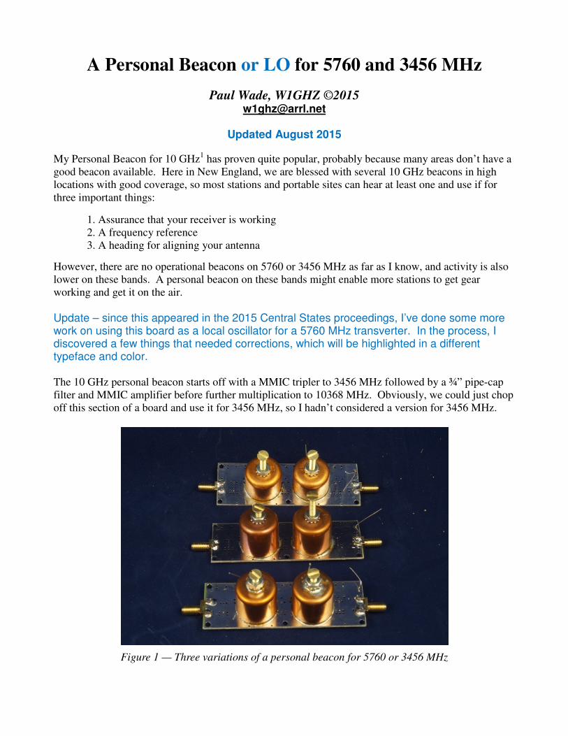
Figure 1 — Three variations of a personal beacon for 5760 or 3456 MHz

However, for 5760 MHz, we would be multiplying x5 so a lot less output might be expected, and more
amplification is probably necessary. Since two pipe-cap filters do a decent job of filtering at 10 GHz, a
second pipe-cap might be good at 5760 MHz. So a good lineup might be: MMIC x5 multiplier, pipe-
cap filter, MMIC amplifier, pipe-cap filter, and MMIC amplifier. The schematic is shown in Figure 2.
With ¾” pipe-caps, this fits comfortably on a PC board the same size as the 10 GHz version.
Figure 2 – Schematic diagram of Personal Beacon for 5760 or 3456 MHz
Update – ERA-2 data sheet recommends 110 ohms for R1, R2, and R3
My first prototype produced a couple of milliwatts at 5760 MHz with an input at 1152 MHz, but
nothing I did would increase the output power. My goal is around +10 dBm, enough to drive a mixer
so the board could also be used as on LO for a simple transverter. So I put the project aside for a while
waiting for inspiration.
Eventually, it occurred to me that other input frequencies could be used, with other multiplication
factors. If the signal source is a synthesizer, it isn’t hard to generate other frequencies. One choice
might be to multiply to 2880 MHz, then multiply x2 up to 5760 MHz, if the ¾” pipe –cap would tune
that low in frequency. My pipe-cap filter experiments2 suggested that might be possible.
To make the last option possible, I modified the bias stubs on the PC board so that they could be used
at ~3 GHz by placing a chip capacitor bypass at the very end, or at 5760 MHz by connecting a ¼ λ
stub roughly ¼ λ from the 50Ω main line. I added this modification to all three stages, allowing the
board to operate at 3456 MHz as well.
I assembled three variations on the new PC boards:
1. 5760 directly, all three stages tuned to 5760 MHz
2. 2880 MHz first stage, x2 multiplier to 5760 MHz
3. 3456 MHz, all three stages with the bias network at the 3 GHz position
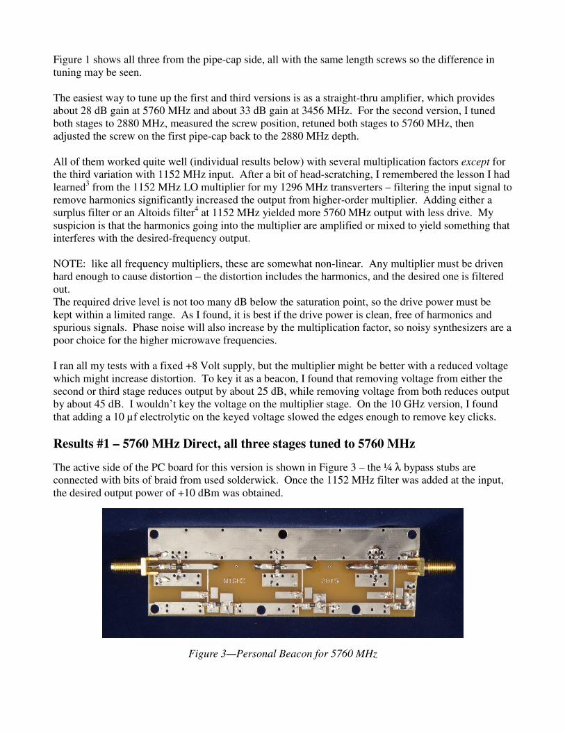
Figure 1 shows all three from the pipe-cap side, all with the same length screws so the difference in
tuning may be seen.
The easiest way to tune up the first and third versions is as a straight-thru amplifier, which provides
about 28 dB gain at 5760 MHz and about 33 dB gain at 3456 MHz. For the second version, I tuned
both stages to 2880 MHz, measured the screw position, retuned both stages to 5760 MHz, then
adjusted the screw on the first pipe-cap back to the 2880 MHz depth.
All of them worked quite well (individual results below) with several multiplication factors except for
the third variation with 1152 MHz input. After a bit of head-scratching, I remembered the lesson I had
learned3 from the 1152 MHz LO multiplier for my 1296 MHz transverters – filtering the input signal to
remove harmonics significantly increased the output from higher-order multiplier. Adding either a
surplus filter or an Altoids filter4 at 1152 MHz yielded more 5760 MHz output with less drive. My
suspicion is that the harmonics going into the multiplier are amplified or mixed to yield something that
interferes with the desired-frequency output.
NOTE: like all frequency multipliers, these are somewhat non-linear. Any multiplier must be driven
hard enough to cause distortion – the distortion includes the harmonics, and the desired one is filtered
out.
The required drive level is not too many dB below the saturation point, so the drive power must be
kept within a limited range. As I found, it is best if the drive power is clean, free of harmonics and
spurious signals. Phase noise will also increase by the multiplication factor, so noisy synthesizers are a
poor choice for the higher microwave frequencies.
I ran all my tests with a fixed +8 Volt supply, but the multiplier might be better with a reduced voltage
which might increase distortion. To key it as a beacon, I found that removing voltage from either the
second or third stage reduces output by about 25 dB, while removing voltage from both reduces output
by about 45 dB. I wouldn’t key the voltage on the multiplier stage. On the 10 GHz version, I found
that adding a 10 µf electrolytic on the keyed voltage slowed the edges enough to remove key clicks.
Results #1 – 5760 MHz Direct, all three stages tuned to 5760 MHz
The active side of the PC board for this version is shown in Figure 3 – the ¼ λ bypass stubs are
connected with bits of braid from used solderwick. Once the 1152 MHz filter was added at the input,
the desired output power of +10 dBm was obtained.
Figure 3—Personal Beacon for 5760 MHz
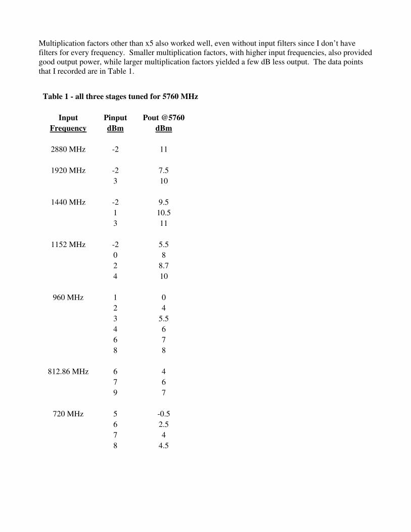
Multiplication factors other than x5 also worked well, even without input filters since I don’t have
filters for every frequency. Smaller multiplication factors, with higher input frequencies, also provided
good output power, while larger multiplication factors yielded a few dB less output. The data points
that I recorded are in Table 1.
Table 1 - all three stages tuned for 5760 MHz
Input Pinput Pout @5760
Frequency dBm dBm
2880 MHz -2 11
1920 MHz -2 7.5
3 10
1440 MHz -2 9.5
1 10.5
3 11
1152 MHz -2 5.5
0 8
2 8.7
4 10
960 MHz 1 0
2 4
3 5.5
4 6
6 7
8 8
812.86 MHz 6 4
7 6
9 7
720 MHz 5 -0.5
6 2.5
7 4
8 4.5
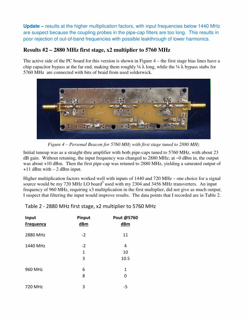
Update – results at the higher multiplication factors, with input frequencies below 1440 MHz
are suspect because the coupling probes in the pipe-cap filters are too long. This results in
poor rejection of out-of-band frequencies with possible leakthrough of lower harmonics.
Results #2 – 2880 MHz first stage, x2 multiplier to 5760 MHz
The active side of the PC board for this version is shown in Figure 4 – the first stage bias lines have a
chip capacitor bypass at the far end, making them roughly ¼ λ long, while the ¼ λ bypass stubs for
5760 MHz are connected with bits of braid from used solderwick.
Figure 4 – Personal Beacon for 5760 MHz with first stage tuned to 2880 MHz
Initial tuneup was as a straight-thru amplifier with both pipe-caps tuned to 5760 MHz, with about 23
dB gain. Without retuning, the input frequency was changed to 2880 MHz; at ~0 dBm in, the output
was about +10 dBm. Then the first pipe-cap was retuned to 2880 MHz, yielding a saturated output of
+11 dBm with – 2 dBm input.
Higher multiplication factors worked well with inputs of 1440 and 720 MHz – one choice for a signal
source would be my 720 MHz LO board5 used with my 2304 and 3456 MHz transverters. An input
frequency of 960 MHz, requiring x3 multiplication in the first multiplier, did not give as much output;
I suspect that filtering the input would improve results. The data points that I recorded are in Table 2.
Table 2 - 2880 MHz first stage, x2 multiplier to 5760 MHz
Input Pinput Pout @5760
Frequency dBm dBm
2880 MHz -2 11
1440 MHz -2 4
1 10
3 10.5
960 MHz 6 1
8 0
720 MHz 3 -5
4 4
5 8
6 9
7 9
Update – results at the higher multiplication factors, with input frequencies below 1440 MHz are suspect because the coupling probes in the pipe-cap filter at 5760 MHz are too long. This results in poor rejection of out-of-band frequencies with possible leakthrough of lower harmonics.
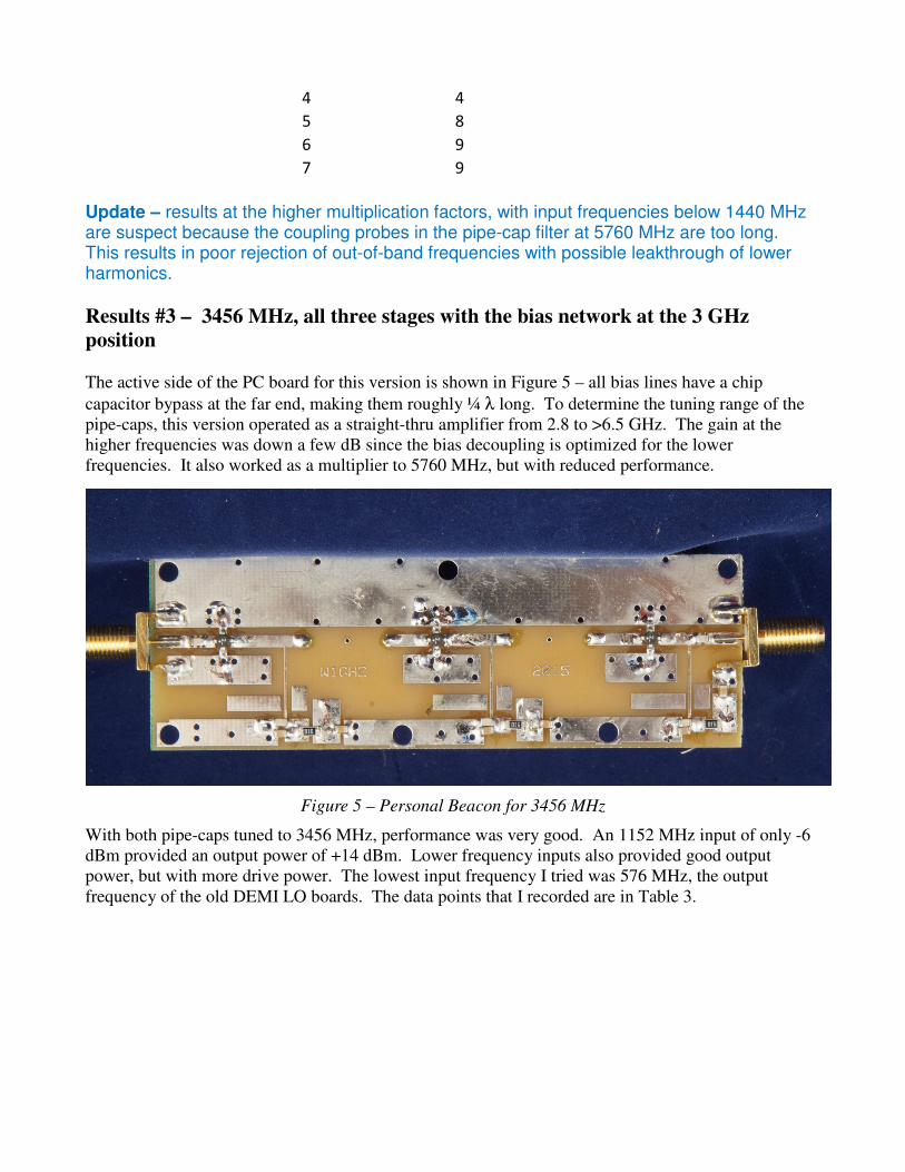
Results #3 – 3456 MHz, all three stages with the bias network at the 3 GHz
position
The active side of the PC board for this version is shown in Figure 5 – all bias lines have a chip
capacitor bypass at the far end, making them roughly ¼ λ long. To determine the tuning range of the
pipe-caps, this version operated as a straight-thru amplifier from 2.8 to >6.5 GHz. The gain at the
higher frequencies was down a few dB since the bias decoupling is optimized for the lower
frequencies. It also worked as a multiplier to 5760 MHz, but with reduced performance.
Figure 5 – Personal Beacon for 3456 MHz
With both pipe-caps tuned to 3456 MHz, performance was very good. An 1152 MHz input of only -6
dBm provided an output power of +14 dBm. Lower frequency inputs also provided good output
power, but with more drive power. The lowest input frequency I tried was 576 MHz, the output
frequency of the old DEMI LO boards. The data points that I recorded are in Table 3.
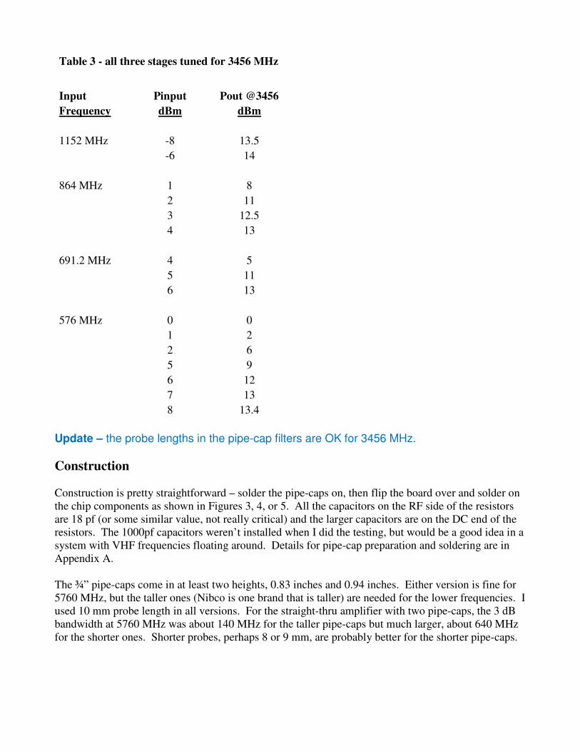
Table 3 - all three stages tuned for 3456 MHz
Input Pinput Pout @3456
Frequency dBm dBm
1152 MHz -8 13.5
-6 14
864 MHz 1 8
2 11
3 12.5
4 13
691.2 MHz 4 5
5 11
6 13
576 MHz 0 0
1 2
2 6
5 9
6 12
7 13
8 13.4
Update – the probe lengths in the pipe-cap filters are OK for 3456 MHz.
Construction
Construction is pretty straightforward – solder the pipe-caps on, then flip the board over and solder on
the chip components as shown in Figures 3, 4, or 5. All the capacitors on the RF side of the resistors
are 18 pf (or some similar value, not really critical) and the larger capacitors are on the DC end of the
resistors. The 1000pf capacitors weren’t installed when I did the testing, but would be a good idea in a
system with VHF frequencies floating around. Details for pipe-cap preparation and soldering are in
Appendix A.
The ¾” pipe-caps come in at least two heights, 0.83 inches and 0.94 inches. Either version is fine for
5760 MHz, but the taller ones (Nibco is one brand that is taller) are needed for the lower frequencies. I
used 10 mm probe length in all versions. For the straight-thru amplifier with two pipe-caps, the 3 dB
bandwidth at 5760 MHz was about 140 MHz for the taller pipe-caps but much larger, about 640 MHz
for the shorter ones. Shorter probes, perhaps 8 or 9 mm, are probably better for the shorter pipe-caps.
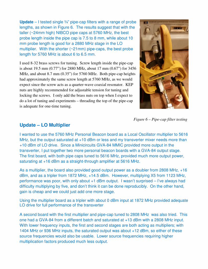
Update – I tested single ¾” pipe-cap filters with a range of probe
lengths, as shown in Figure 6. The results suggest that with the
taller (~24mm high) NIBCO pipe caps at 5760 MHz, the best
probe length inside the pipe cap is 7.5 to 8 mm, while about 10
mm probe length is good for a 2880 MHz stage in the LO
multiplier. With the shorter (~21mm) pipe-caps, the best probe
length for 5760 MHz is about 6 to 6.5 mm.
I used 8-32 brass screws for tuning. Screw length inside the pipe-cap
is about 19.5 mm (0.77”) for 2880 MHz, about 17 mm (0.67”) for 3456
MHz, and about 8.7 mm (0.35”) for 5760 MHz. Both pipe-cap heights
had approximately the same screw length at 5760 MHz, as we would
expect since the screw acts as a quarter-wave coaxial resonator. KEP
nuts are highly recommended for adjustable tension for tuning and
locking the screws. I only add the brass nuts on top when I expect to
do a lot of tuning and experiments – threading the top of the pipe-cap
is adequate for one-time tuning.
Update – LO Multiplier
I wanted to use the 5760 MHz Personal Beacon board as a Local Oscillator multiplier to 5616
MHz, but the output saturated at +10 dBm or less and my transverter mixer needs more than
+10 dBm of LO drive. Since a Minicircuits GVA-84 MMIC provided more output in the
transverter, I put together two more personal beacon boards with a GVA-84 output stage.
The first board, with both pipe caps tuned to 5616 MHz, provided much more output power,
saturating at +16 dBm as a straight-through amplifier at 5616 MHz.
As a multiplier, the board also provided good output power as a doubler from 2808 MHz, +16
dBm, and as a tripler from 1872 MHz, +14.5 dBm. However, multiplying X5 from 1123 MHz,
performance was poor, with only about +1 dBm output. I wasn’t surprised – I’ve always had
difficulty multiplying by five, and don’t think it can be done reproducibly. On the other hand,
gain is cheap and we could just add one more stage.
Using the multiplier board as a tripler with about 0 dBm input at 1872 MHz provided adequate LO drive for full performance of the transverter A second board with the first multiplier and pipe-cap tuned to 2808 MHz was also tried. This
one had a GVA-84 from a different batch and saturated at +13 dBm with a 2808 MHz input.
With lower frequency inputs, the first and second stages are both acting as multipliers; with
1404 MHz or 936 MHz inputs, the saturated output was about +12 dBm, so either of these
source frequencies would also be usable. Lower source frequencies requiring higher
multiplication factors produced much less output.
Figure 6 – Pipe-cap filter testing
Summary
It has probably occurred to you by now that this board has a number of possible uses. For any
frequency from about 2.8 GHz to >6 GHz, it can be a multiplier to provide a signal, or just a bandpass
amplifier, providing filtering and gain. The +10 dBm power level is more than adequate to provide LO
for a mixer, but higher power might be possible with a device like an ERA-4 or ERA-5 in the output
stage. The MMIC footprints will also accommodate devices in the SOT-89 package, like the GVA-
and GALI- series MMICs from Minicircuits.
Another possibility that just occurred to me would be a single-band preamp – the PHA-1 MMIC has
respectable gain and noise figure at these frequencies, and three stages would provide adequate overall
gain even with pipe-cap filter loss. The only change required to the board would be to replace the
resistors with SMT RF chokes. I will have to give this a try.
PC boards are available – www.w1ghz.org
References
1. Paul Wade, W1GHZ, “Multiband Microwave Transverters for the Rover,”
http://www.w1ghz.org/MBT/Multiband_Four_Microwave_Transverters.pdf
2. Paul Wade, W1GHZ, “Pipe-cap Filters Revisited,” www.w1ghz.org/new/Pipe-
cap_Filters_Revisited.pdf
3. Paul Wade, W1GHZ, “Locked VCXOs for Stable Microwave Local Oscillators with Low
Phase Noise,”
http://www.w1ghz.org/small_proj/VCXO_for_Microwave_LO_update2.pdf
4. Paul Wade, W1GHZ, “Altoids_Tin_Filters,”
http://www.w1ghz.org/filter/Altoids_Tin_Filters.pdf

Appendix – Pipe-cap Filter Assembly
A pipe-cap filter sketch is shown in Figure A1. This is the procedure I use to install the pipe-cap filters.
For each pipe cap, I measure from the holes and scribe a square on the ground plane that the pipe cap
just fits inside. Next I prepare each pipe cap by drilling and tapping (use lots of oil, but clean it off) the
hole for an 8-32 tuning screw, then flattening the open end by sanding on a flat surface. Then I apply
resin paste flux lightly to the open end, and to the area around the screw hole for a brass nut to extend
the thread length. The nut is not necessary, but it makes tuning smoother. The nut is held in place for
soldering with a temporary stainless-steel screw. (Solder won't stick to it.) Next I center the open end
of each cap in the scribed square on the PC board - the flux holds it in place. Finally, I fit a circle of
thin wire solder around the base of each pipe cap and nut. The caps are soldered one at a time, starting
with the center one. I hold each cap down with gentle pressure and heat it for a few seconds with a hot
air gun, like a paint stripper, until the solder melts and flows into the joints, then let the solder harden
before releasing pressure.
Figure A1 - Pipe-Cap Filter sketch
I found that using disc capacitor leads for the probes makes it easier to control the depth, as shown in
Figure A2. The leads fit the holes well, and the capacitor provides enough tension to keep them from
slipping while soldering. Just measure the height to the bottom of the disc with the leads resting on the
board, then insert the leads the desired distance plus the board thickness, 0.062 inches (1.5 mm). C4 is
in the test position in this photo, ready for tuneup as soon as the capacitor leads are soldered and cut
off. And the disc capacitor is still usable – a VHFer would never use more than ¼ inch lead length.
Figure A2 - Inserting probes into pipe-cap filters
Recommended