Product information PI 54 en
Machining unit 0.5.030.xxxSlide unit 0.2.200.xxx
2016-03-01


3
®
PI 54 e
PI_54_en_2016-02-29.fm
Table of Contents
Machining Unit
Brief Description .............................................................................................................................4
Technical Data ..............................................................................................................................6
Dimensions.....................................................................................................................................7
Precision.........................................................................................................................................8
Installation Options.........................................................................................................................9
Application Examples ...................................................................................................................10
Slide Unit
Brief Description ...........................................................................................................................12
Technical Data ............................................................................................................................14
Dimensions...................................................................................................................................15
Installation Options.......................................................................................................................16
Spindle heads
Features .......................................................................................................................................18
Spindle Heads 0° Selection..........................................................................................................19
Admissible Loads .........................................................................................................................20
Spindle Heads 90° Selection........................................................................................................21
Precision.......................................................................................................................................22
Ordering details
Machining Unit..............................................................................................................................23
Spindle Heads..............................................................................................................................24
Slide Unit ......................................................................................................................................25
NOTE:The information contained in this product information is based on the knowledge available at the time of printing. We expressly reserve the right to make changes which occur in line with continuous development.Our guarantee demands observance of the information provided in the project planning instructions!
Table of Contents

®
4 PI 54 e
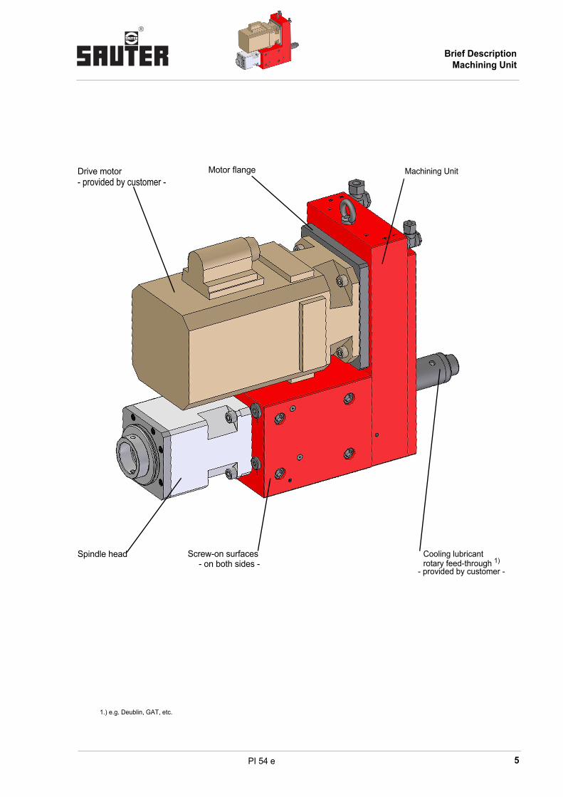
Brief description of machining unit
Machining units are used particularly for machining stations of transfer lines,revolving transfer machines and for turning machines.
Features
• Prepared for high-power servomotors
• High torque capacity.
• Protection of all tool spindles against swarf and cooling lubricant bylabyrinth seals supported by sealing air
• Cooling lubricant supply
– externally by the spindle head housing or
– internally by the tool spindle (suitable for dry running)
– Minimal quantity lubrication (optional)
• Universal installation
• Expansion of the application areas of your machine
• Other versions on request
Brief DescriptionMachining Unit
5
®
PI 54 e
Motor flangeDrive motor- provided by customer -
Screw-on surfaces- on both sides -
Cooling lubricantrotary feed-through 1)
- provided by customer -
Spindle head
Machining Unit
1.) e.g. Deublin, GAT, etc.
Brief DescriptionMachining Unit

®
6 PI 54 e
Technical Data of Machining Unit
Series Size
Machining unit 0.5.030.0xx 06
Max. permitted drive speed 1.) min-1 6000
Max. permitted drive torque 3.) Nm 100
Max. permitted output torque Nm 150
Max. permitted drive rating kW 12
Transmission ratio 2.) (Options) i = n1/n2 2,4 (1,0 / 1,5 / 2,0)
Mass (machining unit without motor and without spindle head) kg 70
Operating pressure
Sealing air bar 0.4 - 0.8 (filtering <5µm)
Cooling lubricant
• for external supply through the spindle head housing bar < 25 (filtering <100µm)
• for internal supply through the tool spindle bar <100 (filtering <50µm)
• for minimal quantity lubrication bar On request
Recommended drive motors
SIEMENS 1FT6 086
rpm nmax min-1 6000
Torque Mmax 60% DC Nm 35
Power Pmax 60% DC kW 12
Mass kg 26
FANUC Alpha 30 / 4000HVis
rpm nmax min-1 4000
Torque Mmax 60% DC Nm 38
Power Pmax 60% DC kW 12
Mass kg 23
For this purpose SAUTER spindle heads
0.5.934.1.. 0.5.934.2..
1.) Higher rpm on request
2.) Other transmissions on request.
3.) Madm is the admissible peak load for the gearbox.
The torque must be reduced to the indicated value on the motor inverter. Also consider the gear ratio. The usable performance data depends on the performance characteristic of the motor type used. The permitted torque can be used for shock-free machining. For high-shock machining – e.g. cutter head milling, etc. – the drive torque must be reduced considerably to prevent an overload of the gearbox.
Technical DataMachining Unit

7
®
PI 54 e
Dimensions of Machining Unit
Series Size
Machining unit 0.5.030.0xx 06
B mm 187
C mm 77
D mm 360,5
E mm 78
F mm depending on transmission ratio
G mm 88
H mm 176
L mm depending on motor manufacturer and motor type
K mm depending on spindle head length
Mmax. mm 87,5
U mm 146
T mm 72
SG M12
SL mm 20
Y mm 28
X mm 120
Z mm 45
W mm 45
Cooling lubricant connection (external)
DimensionsMachining Unit

®
8 PI 54 e
Precision of Machining Unit
Positioning accuracy
• Spindle head location hole
- Positioning accuracy
- Bore tolerance H6
Spindle head contact surface
To determine the positioning accuracy of the tool tip, the accuracy of the spindle head and tools must also be considered
Precision Machining Unit

9
®
PI 54 e
Installation options
Adjustment parts for installation on the head turret 0.5.320.xxx with tool holder in accordance with DIN 69881
Installation option 1
Installation option 2
Tool holder - adapter-without height adjustment-
42
NG
140
Alignment device
Tool holder - adapter-with manual height adjustment-
Stroke ± 11 mm
95
NG
140
Installation options

®
10 PI 54 e
Application examples:
Head turret 0.5.320.xxx
Slide unit 0.2.201.036
Other installation options on request
Application examples

11
®
PI 54 e
Notes
Notes

®
12 PI 54 e
Brief description of slide unit
These slide units are particularly suitable for accommodating machining units. Installation is e.g. on a bidirectional head turret.
Features
• Slide unit designed as a compact dovetail guide.
• Central lubrication connection.
• Cooling lubricant supply via the interface DIN 69881.
• Slide position via motor encoder.
• Expansion of the application area of your machine.
• Quick installation by precision quick-change system. (e.g. SPEEDY metec)
• High repeating accuracy by alignment device.
• Other versions on request.
Brief DescriptionSlide Unit

13
®
PI 54 e
Drive motor -provided by -customer-
Attachment drilling pattern for machining unit
Central terminal box -option -
Slide Unit
Central lubrication connection
Alignment device
Brief DescriptionSlide Unit

®
14 PI 54 e
Technical Data of Slide Unit
Series Size
Slide unit 0.2.200.0xx 25
Gearing ratio i 1
Gradient of the ball roller spindle mm 5
Adm. rapid feed rate m/min 10
Working stroke mm ±100
Adm. feed force kN 1
Adm. motor drive speed min-1 2000
Adm. motor drive torque Nm 3
Length measuring systemMotor
encoder
Achievable positioning accuracy µm 10
Mass (slide unit without machining unit, without spindle head and without motor) kg 125
Recommended drive motors
SIEMENS 1FK7 042 with brake
Speed 1.) nmax min-1 3000
Torque 1.) Mmax 60% DC Nm 3,2
Mass kg 5,4
FANUC Alpha 2 / 5000 is with brakeFANUC Alpha 2 / 5000 HVis with brake
Speed 1.) nmax min-1 5000
Torque 1.) Mmax 60% DC Nm 2,6
Mass kg 3,8
1.) Limit motor to adm. values of the slide unit.
Technical DataSlide Unit

15
®
PI 54 e
Series Size
Slide unit 0.2.200.0xx 25
B mm 108
C mm 130
D mm 260
H mm 228
±H mm 100
M mm 542
Y mm 105
X mm 120
R (Grid) mm 30
Z mm 90
W mm 45
DimensionsSlide Unit

®
16 PI 54 e
Installation options
Adjustment parts for installation on the head turret 0.5.320.xxx with tool holder
Installation options
KSS out-put to theKSS supply from
head turretin accordance
Tool holder - adapterwith quick-change system
Central terminal box- Option -
Cable carrier- Option -
42
NG
140
300

17
®
PI 54 e
Notes
Notes

®
18 PI 54 e
Spindle heads of series 0.5.934.xxx
Features
• Bearing assembly via precision spindle bearings in -O- or tandem-O-arrangement,moderate preload
• Service life grease lubrication
• Wear-free labyrinth seal with sealing air support
• Cooling lubricant supply:
– externally by the spindle head housing or
– internally by the tool spindle
• Very high concentricity and degree of balance
• Tool holder in the spindle: for HSK/Mapal clamping system
• Transmission i = 1
Options
• Special tool holders
• Spindle bearings (selection):
– for high speed
– for high load
– for special requests
• Other options on request:
• Spindle heads with transmission i ‡ 1
– Multi-spindle drill heads
. . .
Features of the Spindle

19
®
PI 54 e
Application recommendation:
Bearing arrangement << O > – for higher loads.
Internal cooling lubricant supply – suitable for dry running.
Spindle head 0° selection 0.5.934.xxx
Shaft diameter D
Tool
holder1)
1) Including clamping unit from Mapal, type KS..-07 clamping unit and guard ring.
Arrangement of bearings
Size Length L
60
HSK 50-C < O > 106 138
HSK 63-C < O > 106 138
HSK 63-C << O > 106 138
HSK 63-C << O > 106 180
HSK 63-C << O >> 106 -
Spindle head 0° selection

®
20 PI 54 e
Permitted axial force during drilling
Permitted transverse force during milling
Characteris-tic no.
Bearing arrangement
Nominal bearing service life
Lh [h]
1 Standard 4000
2 Tandem 4000
3 Standard 8000
4 Tandem 8000
Characteris-tic no.
Bearing arrange-ment
Bearing spac-ing
LW [mm]
1 Tandem Long
802 Tandem Standard
3 Standard Standard
4 Tandem Long
1605 Tandem Standard
6 Standard Standard
0,00
1,00
2,00
3,00
4,00
5,00
6,00
7,00
10002000
30004000
50006000
0.5.934.106
n [1/min]
F[k
N]
ax
2
4
1
3
LW
Admissible Loads
21
®
PI 54 e
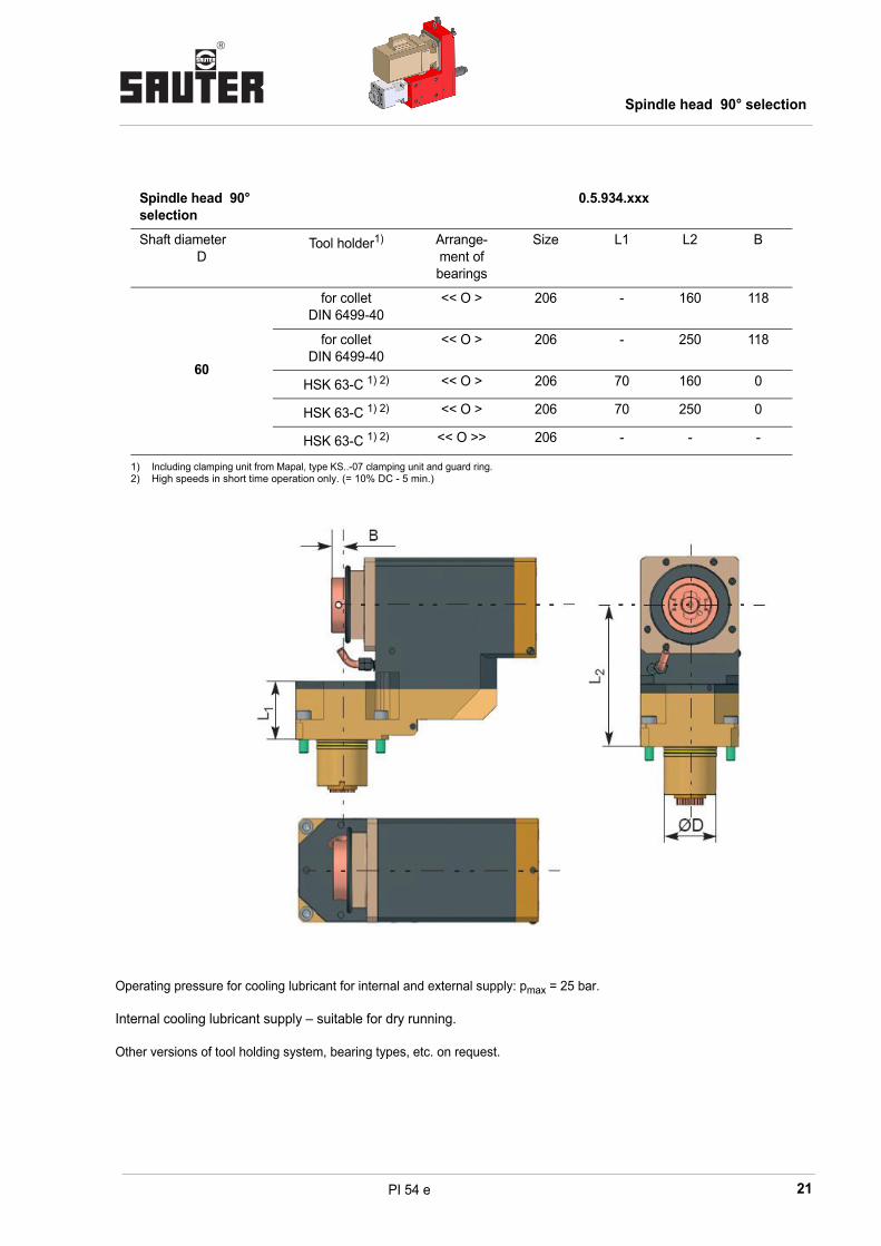
Operating pressure for cooling lubricant for internal and external supply: pmax = 25 bar.
Internal cooling lubricant supply – suitable for dry running.
Other versions of tool holding system, bearing types, etc. on request.
Spindle head 90° selection
0.5.934.xxx
Shaft diameter D
Tool holder1)
1) Including clamping unit from Mapal, type KS..-07 clamping unit and guard ring.
Arrange-ment of bearings
Size L1 L2 B
60
for collet DIN 6499-40
<< O > 206 - 160 118
for collet DIN 6499-40
<< O > 206 - 250 118
HSK 63-C 1) 2)
2) High speeds in short time operation only. (= 10% DC - 5 min.)
<< O > 206 70 160 0
HSK 63-C 1) 2) << O > 206 70 250 0
HSK 63-C 1) 2) << O >> 206 - - -
Spindle head 90° selection
®
22 PI 54 e
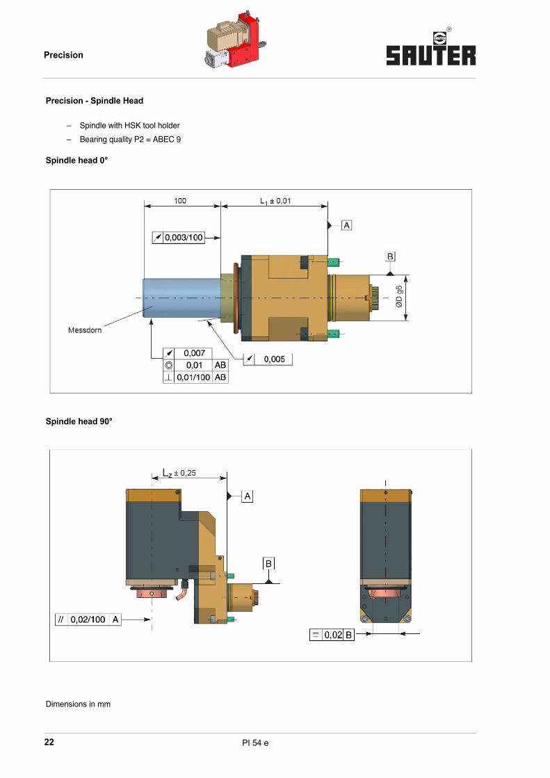
Precision - Spindle Head
– Spindle with HSK tool holder
– Bearing quality P2 = ABEC 9
Spindle head 0°
Spindle head 90°
Dimensions in mm
Precision
23
®
PI 54 e
Firma:
Straße:
PLZ, Ort:
Name:
Tel.:
++49 (0) 7123-926-190
++49 (0) 123-926-0
Sauter Feinmechanik GmbHPostfach 1551D-72545 MetzingenGermany
Fax:
E-Mail:
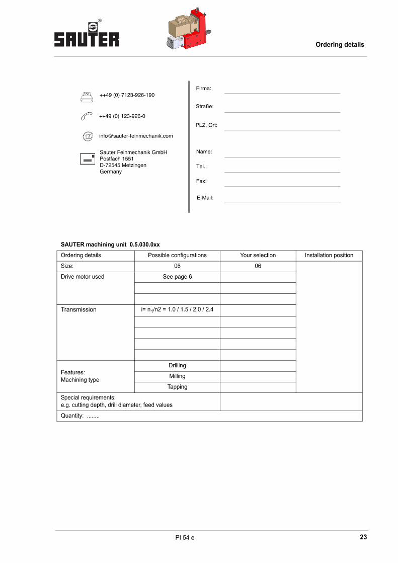
SAUTER machining unit 0.5.030.0xx
Ordering details Possible configurations Your selection Installation position
Size: 06 06
Drive motor used See page 6
Transmission i= n1/n2 = 1.0 / 1.5 / 2.0 / 2.4
Features:Machining type
Drilling
Milling
Tapping
Special requirements: e.g. cutting depth, drill diameter, feed values
Quantity: ........
Ordering details

®
24 PI 54 e
SAUTER spindle heads 0.5.934.xxx
Ordering details Possible configurations Your selection
Size: 06
Tool holder: HSK 50
HSK 63
including Mapal clamping unit
Special
Bearing spacing/bearing arrange-ment:
Standard / -O-
Standard / Tandem -O-
Standard / Special
Long / Tandem -O-
Long / Special
Application features: Drilling nmax = ..... min-1
Milling Md = ..... Nm
Other ......
Transmission: i = ....
Special requirements: Sketch is enclosed
Quantity: .......
SAUTER slide unit 0.2.200.xxx
Ordering details Possible configura-tions
Your selection Installation position
Size: 025
Working stroke + 100
Drive motor used See page 14
Quantity: .........
Ordering details
Recommended