1/ 5
PK10/S RK Series
Model Length (L) mm
Width (W)mm
Height (H) mm
Dry Weightkg
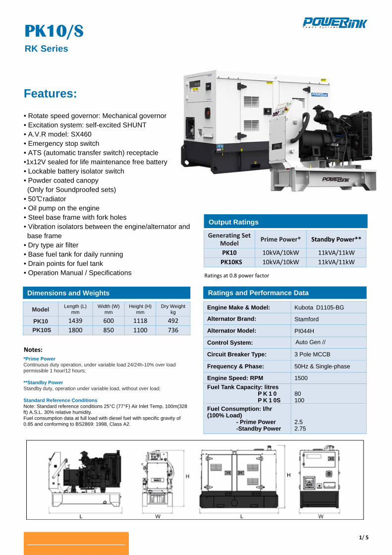
PK10 1439 600 1118 492PK10S 1800 850 1100 736
Features: • Rotate speed governor: Mechanical governor • Excitation system: self-excited SHUNT • A.V.R model: SX460 • Emergency stop switch • ATS (automatic transfer switch) receptacle •1x12V sealed for life maintenance free battery • Lockable battery isolator switch • Powder coated canopy (Only for Soundproofed sets) • 50℃radiator • Oil pump on the engine • Steel base frame with fork holes • Vibration isolators between the engine/alternator and base frame
• Dry type air filter • Base fuel tank for daily running • Drain points for fuel tank • Operation Manual / Specifications
Notes: ***
Ratings at 0.8 power factor
Engine Make & Model: Kubota D1105BG
Alternator Brand: Stamford
Alternator Model: PI044H
Control System: Auto Gen //
Circuit Breaker Type: 3 Pole MCCB
Frequency & Phase: 50Hz & Single-phase
Engine Speed: RPM 1500 Fuel Tank Capacity: litres P K 1 0 P K 1 0S
80 100
Fuel Consumption: l/hr (100% Load)
- Prime Power -Standby Power
2.5 2.75
Generating Set Model Prime Power* Standby Power**
PK10 10kVA/10kW 11kVA/11kWPK10KS 10kVA/10kW 11kVA/11kW
Dimensions and Weights
Output Ratings
Ratings and Performance Data
*Prime Power Continuous duty operation, under variable load 24/24h-10% over load permissible 1 hour/12 hours; **Standby Power Standby duty, operation under variable load, without over load; Standard Reference Conditions Note: Standard reference conditions 25°C (77°F) Air Inlet Temp, 100m(328ft) A.S.L. 30% relative humidity. Fuel consumption data at full load with diesel fuel with specific gravity of 0.85 and conforming to BS2869: 1998, Class A2.
2/ 5
PK10/S RK Series
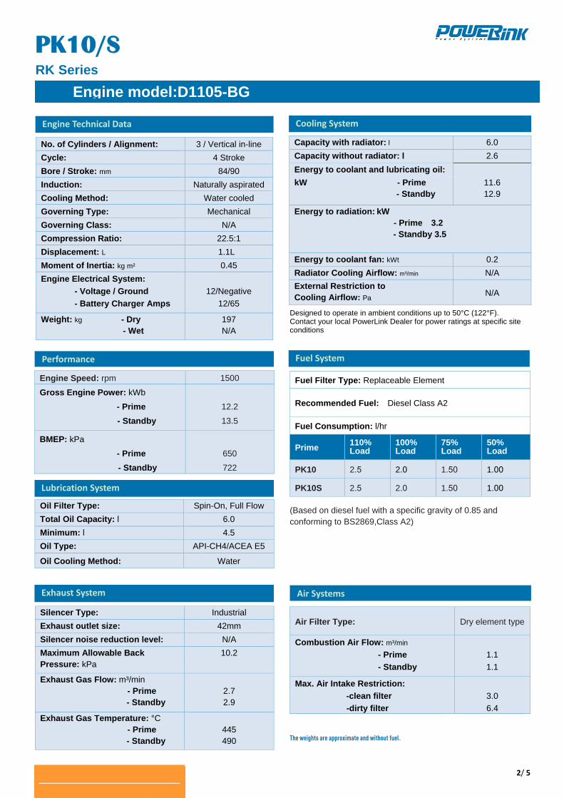
Engine Speed: rpm 1500
Gross Engine Power: kWb
- Prime - Standby
12.2
13.5
BMEP: kPa
- Prime - Standby
650
722
Capacity with radiator: l 6.0 Capacity without radiator: l 2.6 Energy to coolant and lubricating oil:
kW - Prime - Standby
11.6 12.9
Energy to radiation: kW
- Prime 3.2 - Standby 3.5
Energy to coolant fan: kWt 0.2 Radiator Cooling Airflow: m³/min N/A External Restriction to Cooling Airflow: Pa N/A
No. of Cylinders / Alignment: 3 / Vertical in-line Cycle: 4 Stroke Bore / Stroke: mm 84/90 Induction: Naturally aspiratedCooling Method: Water cooled Governing Type: Mechanical Governing Class: N/A Compression Ratio: 22.5:1 Displacement: L 1.1L Moment of Inertia: kg m² 0.45 Engine Electrical System:
- Voltage / Ground - Battery Charger Amps
12/Negative
12/65
Weight: kg - Dry - Wet
197 N/A
Oil Filter Type: Spin-On, Full Flow Total Oil Capacity: l 6.0 Minimum: l 4.5 Oil Type: API-CH4/ACEA E5
Oil Cooling Method: Water
Silencer Type: Industrial Exhaust outlet size: 42mm Silencer noise reduction level: N/A Maximum Allowable Back Pressure: kPa
10.2
Exhaust Gas Flow: m³/min - Prime - Standby
2.7 2.9
Exhaust Gas Temperature: °C - Prime - Standby
445 490
Designed to operate in ambient conditions up to 50°C (122°F). Contact your local PowerLink Dealer for power ratings at specific site conditions
Fuel Filter Type: Replaceable Element
Recommended Fuel: Diesel Class A2
Fuel Consumption: l/hr
Prime 110% Load
100% Load
75% Load
50% Load
PK10 2.5 2.0 1.50 1.00
PK10S 2.5 2.0 1.50 1.00
(Based on diesel fuel with a specific gravity of 0.85 and conforming to BS2869,Class A2)
The weights are approximate and without fuel.
Air Filter Type: Dry element type
Combustion Air Flow: m³/min
- Prime - Standby
1.1 1.1
Max. Air Intake Restriction: -clean filter -dirty filter
3.0 6.4
Engine Technical Data
Exhaust System
Fuel System
Air Systems
Engine model:D1105BG
Performance
Lubrication System
Cooling System
3/ 5
PK10/S RK Series
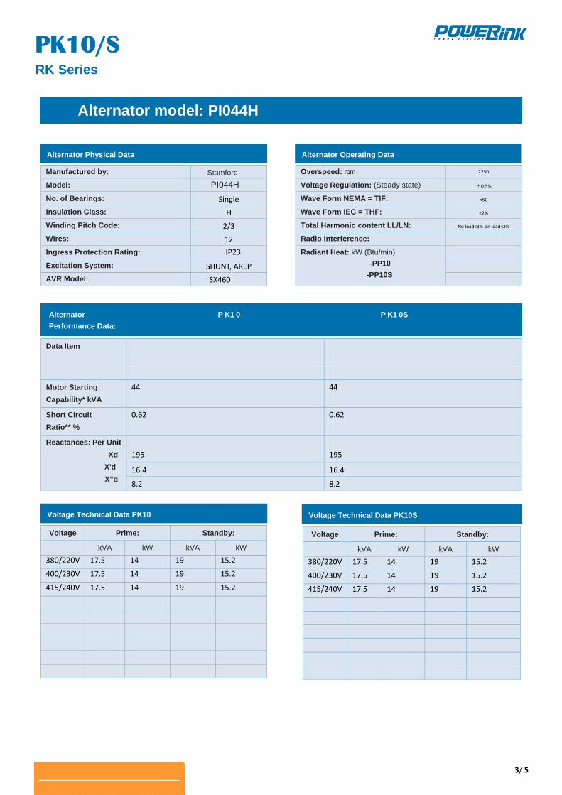
Manufactured by: StamfordModel: PI044H No. of Bearings: Single
Insulation Class: H
Winding Pitch Code: 2/3
Wires: 12
Ingress Protection Rating: IP23
Excitation System: SHUNT, AREP
AVR Model: SX460
Overspeed: rpm 2250
Voltage Regulation: (Steady state) ±0.5%
Wave Form NEMA = TIF: <50
Wave Form IEC = THF: <2%
Total Harmonic content LL/LN: No load<3%‐on load<2%
Radio Interference:
Radiant Heat: kW (Btu/min) -PP10
-PP10S
Data Item
Motor Starting Capability* kVA
44 44
Short Circuit Ratio** %
0.62 0.62
Reactances: Per Unit Xd
X'd X"d
195
195
16.4 16.4
8.2 8.2
Voltage Prime: Standby: kVA kW kVA kW
380/220V 17.5 14 19 15.2
400/230V 17.5 14 19 15.2
415/240V 17.5 14 19 15.2
Voltage Prime: Standby: kVA kW kVA kW
380/220V 17.5 14 19 15.2
400/230V 17.5 14 19 15.2
415/240V 17.5 14 19 15.2
Alternator model: PI044H
Alternator Operating Data
Alternator P K1 0 P K1 0S Performance Data:
Alternator Physical Data
Voltage Technical Data PK10S Voltage Technical Data PK10
4/ 5
PK10/S RK Series
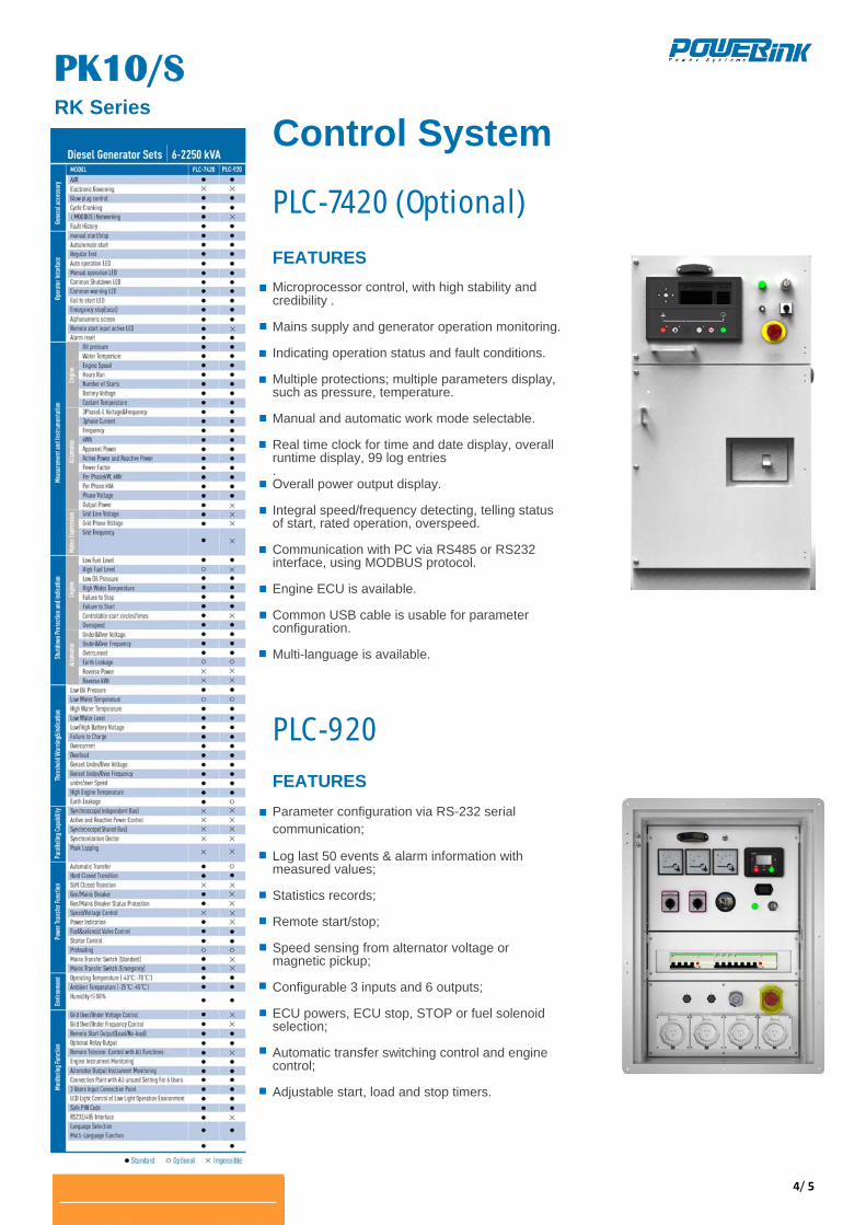
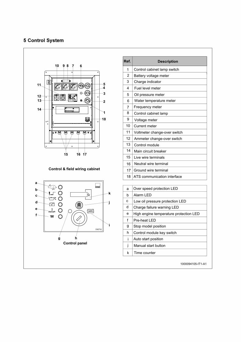
Control System
PLC-7420 (Optional)
FEATURES
Microprocessor control, with high stability and credibility . Mains supply and generator operation monitoring.
Indicating operation status and fault conditions. Multiple protections; multiple parameters display, such as pressure, temperature. Manual and automatic work mode selectable. Real time clock for time and date display, overall runtime display, 99 log entries . Overall power output display. Integral speed/frequency detecting, telling status of start, rated operation, overspeed. Communication with PC via RS485 or RS232 interface, using MODBUS protocol. Engine ECU is available. Common USB cable is usable for parameter configuration. Multi-language is available.
PLC-920
FEATURES
Parameter configuration via RS-232 serial communication; Log last 50 events & alarm information with measured values; Statistics records; Remote start/stop; Speed sensing from alternator voltage or magnetic pickup; Configurable 3 inputs and 6 outputs; ECU powers, ECU stop, STOP or fuel solenoid selection; Automatic transfer switching control and engine control; Adjustable start, load and stop timers.
�#$�� $W�d!�'V
5/ 5
Pk10/S RK Series
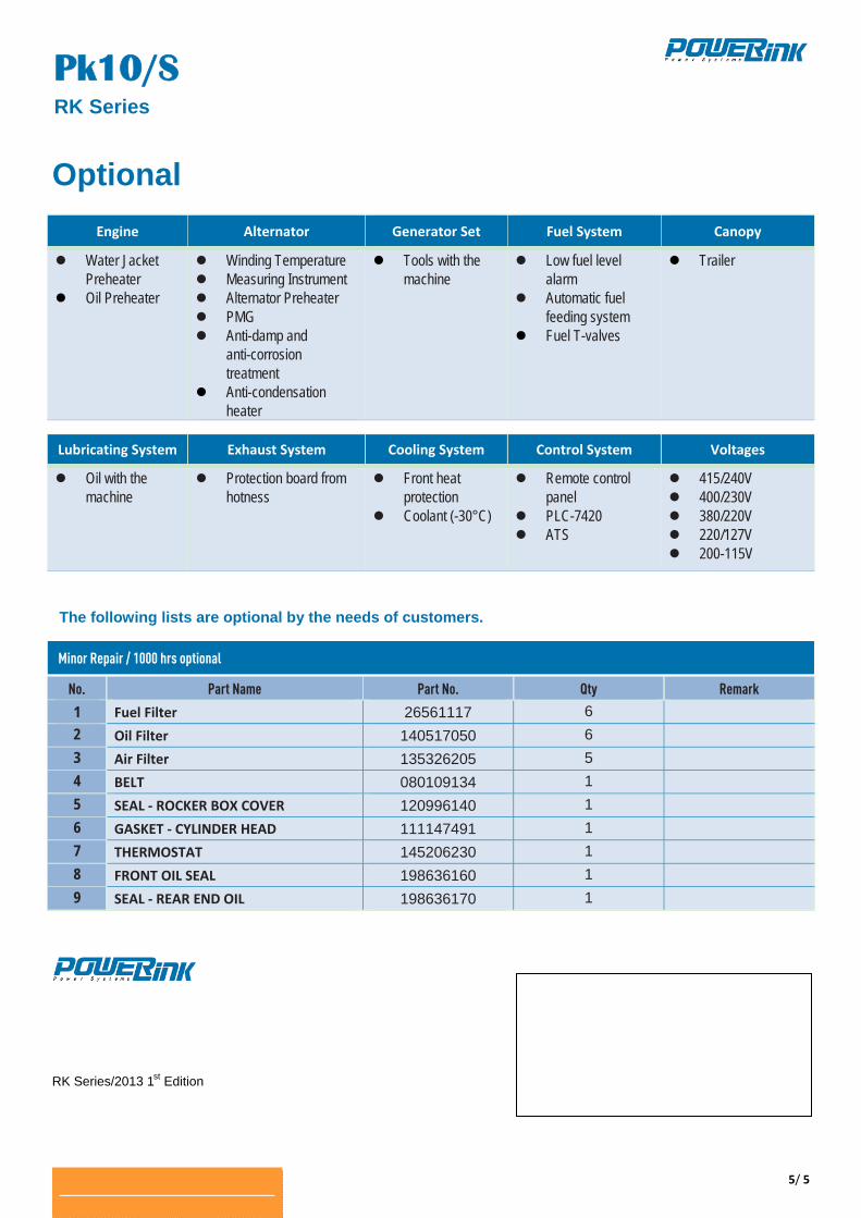
Optional
RK Series/2013 1st Edition
Engine Alternator Generator Set Fuel System Canopy
Water Jacket Preheater
Oil Preheater
Winding Temperature Measuring Instrument Alternator Preheater PMG Anti-damp and
anti-corrosion treatment
Anti-condensation heater
Tools with the machine
Low fuel level alarm
Automatic fuel feeding system
Fuel T-valves
Trailer
Lubricating System Exhaust System Cooling System Control System Voltages
Oil with the machine
Protection board from hotness
Front heat protection
Coolant (-30°C)
Remote control panel
PLC-7420 ATS
415/240V 400/230V 380/220V 220/127V 200-115V
No. Part Name Part No. Qty Remark
1 Fuel Filter 26561117 6
2 Oil Filter 140517050 6
3 Air Filter 135326205 5
4 BELT 080109134 1
5 SEAL ‐ ROCKER BOX COVER 120996140 1
6 GASKET ‐ CYLINDER HEAD 111147491 1
7 THERMOSTAT 145206230 1
8 FRONT OIL SEAL 198636160 1
9 SEAL ‐ REAR END OIL 198636170 1
The following lists are optional by the needs of customers.
Minor Repair / 1000 hrs optional
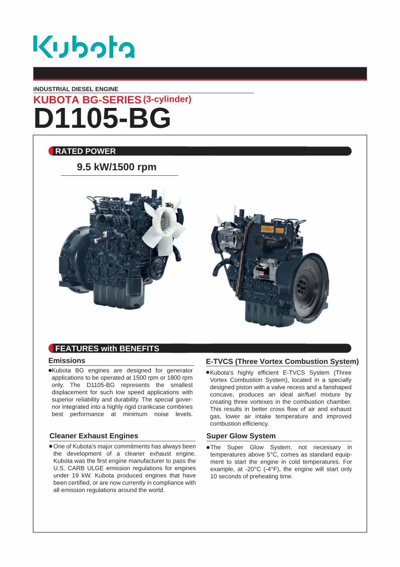
INDUSTRIAL DIESEL ENGINE
D1105-BGRATED POWER
KUBOTA BG-SERIES (3-cylinder)
9.5 kW/1500 rpm
FEATURES with BENEFITSE-TVCS (Three Vortex Combustion System)
Kubota’s highly efficient E-TVCS System (Three Vortex Combustion System), located in a specially designed piston with a valve recess and a fanshaped concave, produces an ideal air/fuel mixture by creating three vortexes in the combustion chamber. This results in better cross flow of air and exhaust gas, lower air intake temperature and improvedcombustion efficiency.
Super Glow SystemThe Super Glow System, not necessary in temperatures above 5°C, comes as standard equip-ment to start the engine in cold temperatures. For example, at -20°C (-4°F), the engine will start only10 seconds of preheating time.
Cleaner Exhaust EnginesOne of Kubota’s major commitments has always beenthe development of a cleaner exhaust engine. Kubota was the first engine manufacturer to pass theU.S. CARB ULGE emission regulations for engines under 19 kW. Kubota produced engines that have been certified, or are now currently in compliance with all emission regulations around the world.
EmissionsKubota BG engines are designed for generator applications to be operated at 1500 rpm or 1800 rpm only. The D1105-BG represents the smallest displacement for such low speed applications with superior reliability and durability. The special gover-nor integrated into a highly rigid crankcase combines best performance at minimum noise levels.
551.3 (21.7)
230.
0 (9
.01)
98.0 (3.86)
396.0 (15.59)
194.0 (7.64)
602.
0 (2
3.7)
227.
6 (8
.96)
360.0 (14.17)
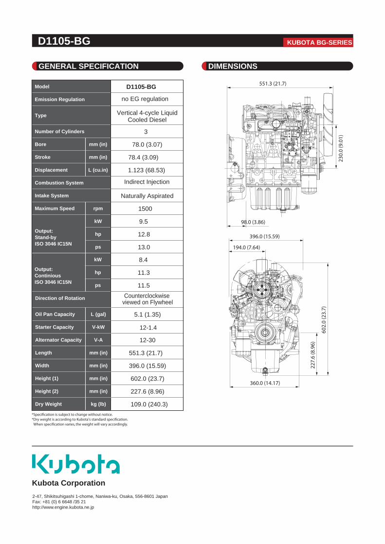
D1105-BG
GENERAL SPECIFICATION DIMENSIONS
KUBOTA BG-SERIES
Kubota Corporation2-47, Shikitsuhigashi 1-chome, Naniwa-ku, Osaka, 556-8601 JapanFax: +81 (0) 6 6648 /35 21http://www.engine.kubota.ne.jp
Model
Emission Regulation
Type
Number of Cylinders
Bore
Stroke
Displacement
Combustion System
Intake System
Maximum Speed
Output:Stand-byISO 3046 IC15N
mm (in)
mm (in)
L (cu.in)
rpm
kW
hp
ps
D1105-BG
no EG regulation
Vertical 4-cycle Liquid Cooled Diesel
3
78.0 (3.07)
78.4 (3.09)
1.123 (68.53)
Indirect Injection
Naturally Aspirated
1500
9.5
12.8
13.0
Output:ContiniousISO 3046 IC15N
kW
hp
ps
8.4
11.3
11.5
Direction of Rotation
Oil Pan Capacity
Starter Capacity
Alternator Capacity
Length
Width
Height (1)
Height (2)
Dry Weight
L (gal)
V-kW
V-A
mm (in)
mm (in)
mm (in)
mm (in)
kg (lb)
Counterclockwise viewed on Flywheel
5.1 (1.35)
12-1.4
12-30
551.3 (21.7)
396.0 (15.59)
602.0 (23.7)
227.6 (8.96)
109.0 (240.3)
When specification varies, the weight will vary accordingly.
AP
PR
OV
ED
DO
CU
ME
NT
PI044H - Winding 311 Single Phase
Technical Data Sheet
AP
PR
OV
ED
DO
CU
ME
NT
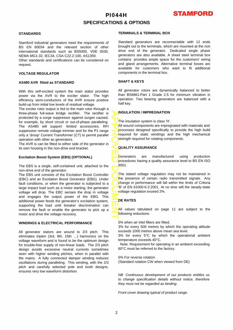
PI044HSPECIFICATIONS & OPTIONS
STANDARDS
Stamford industrial generators meet the requirements ofBS EN 60034 and the relevant section of otherinternational standards such as BS5000, VDE 0530,NEMA MG1-32, IEC34, CSA C22.2-100, AS1359.Other standards and certifications can be considered onrequest.
VOLTAGE REGULATOR
AS480 AVR fitted as STANDARD
With this self-excited system the main stator providespower via the AVR to the exciter stator. The highefficiency semi-conductors of the AVR ensure positivebuild-up from initial low levels of residual voltage.The exciter rotor output is fed to the main rotor through athree-phase full-wave bridge rectifier. The rectifier isprotected by a surge suppressor against surges caused,for example, by short circuit or out-of-phase paralleling.The AS480 will support limited accessories, RFIsuppession remote voltage trimmer and for the P1 rangeonly a 'droop' Current Transformer (CT) to permit paralleloperation with other ac generators.The AVR is can be fitted to either side of the generator inits own housing in the non-drive end bracket.
Excitation Boost System (EBS) (OPTIONAL)
The EBS is a single, self-contained unit, attached to thenon-drive end of the generator.The EBS unit consists of the Excitation Boost Controller(EBC) and an Excitation Boost Generator (EBG). Underfault conditions, or when the generator is subjected to alarge impact load such as a motor starting, the generatorvoltage will drop. The EBC senses the drop in voltageand engages the output power of the EBG. Thisadditional power feeds the generator’s excitation system,supporting the load until breaker discrimination canremove the fault or enable the generator to pick up amotor and drive the voltage recovery.
WINDINGS & ELECTRICAL PERFORMANCE
All generator stators are wound to 2/3 pitch. Thiseliminates triplen (3rd, 9th, 15th …) harmonics on thevoltage waveform and is found to be the optimum designfor trouble-free supply of non-linear loads. The 2/3 pitchdesign avoids excessive neutral currents sometimesseen with higher winding pitches, when in parallel withthe mains. A fully connected damper winding reducesoscillations during paralleling. This winding, with the 2/3pitch and carefully selected pole and tooth designs,ensures very low waveform distortion.
TERMINALS & TERMINAL BOX
Standard generators are reconnectable with 12 endsbrought out to the terminals, which are mounted at the nondrive end of the generator. Dedicated single phasegenerators are also available. A sheet steel terminal boxcontains provides ample space for the customers' wiringand gland arrangements. Alternative terminal boxes areavailable for customers who want to fit additionalcomponents in the terminal box.
SHAFT & KEYS
All generator rotors are dynamically balanced to betterthan BS6861:Part 1 Grade 2.5 for minimum vibration inoperation. Two bearing generators are balanced with ahalf key.
INSULATION / IMPREGNATION
The insulation system is class 'H'.All wound components are impregnated with materials and processes designed specifically to provide the high buildrequired for static windings and the high mechanicalstrength required for rotating components.
QUALITY ASSURANCE
Generators are manufactured using productionprocedures having a quality assurance level to BS EN ISO9001.
The stated voltage regulation may not be maintained inthe presence of certain radio transmitted signals. Anychange in performance will fall within the limits of Criteria'B' of EN 61000-6-2:2001. At no time will the steady-statevoltage regulation exceed 2%.
DE RATES
All values tabulated on page 11 are subject to thefollowing reductions
5% when air inlet filters are fitted.3% for every 500 metres by which the operating altitudeexceeds 1000 metres above mean sea level.3% for every 5°C by which the operational ambienttemperature exceeds 40°C. Note: Requirement for operating in an ambient exceeding 60°C must be referred to the factory.
5% For reverse rotation(Standard rotation CW when viewed from DE)
NB Continuous development of our products entitles usto change specification details without notice, thereforethey must not be regarded as binding.
Front cover drawing typical of product range.
2
AP
PR
OV
ED
DO
CU
ME
NT
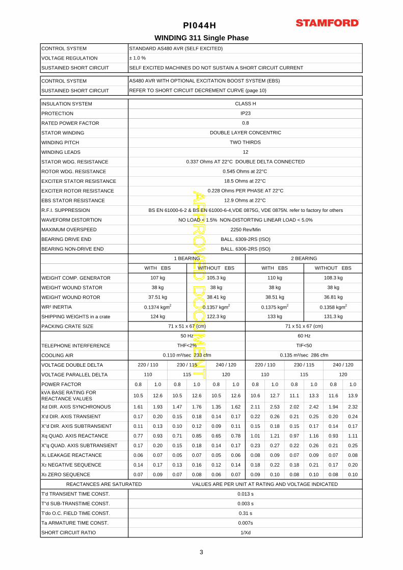
CONTROL SYSTEM STANDARD AS480 AVR (SELF EXCITED)
VOLTAGE REGULATION
SUSTAINED SHORT CIRCUIT SELF EXCITED MACHINES DO NOT SUSTAIN A SHORT CIRCUIT CURRENT
CONTROL SYSTEM
SUSTAINED SHORT CIRCUIT
INSULATION SYSTEM
PROTECTION
RATED POWER FACTOR
STATOR WINDING
WINDING PITCH
WINDING LEADS
STATOR WDG. RESISTANCE
ROTOR WDG. RESISTANCE
EXCITER STATOR RESISTANCE
EXCITER ROTOR RESISTANCE
EBS STATOR RESISTANCE
R.F.I. SUPPRESSION BS EN 61000-6-2 & BS EN 61000-6-4,VDE 0875G, VDE 0875N. refer to factory for others
WAVEFORM DISTORTION NO LOAD < 1.5% NON-DISTORTING LINEAR LOAD < 5.0%
MAXIMUM OVERSPEED 2250 Rev/Min
BEARING DRIVE END BALL. 6309-2RS (ISO)
BEARING NON-DRIVE END BALL. 6306-2RS (ISO)
WEIGHT COMP. GENERATOR
WEIGHT WOUND STATOR
WEIGHT WOUND ROTOR
WR² INERTIA
SHIPPING WEIGHTS in a crate
PACKING CRATE SIZE
TELEPHONE INTERFERENCE
COOLING AIR
VOLTAGE DOUBLE DELTA
VOLTAGE PARALLEL DELTA
POWER FACTOR 0.8 1.0 0.8 1.0 0.8 1.0 0.8 1.0 0.8 1.0 0.8 1.0
kVA BASE RATING FOR REACTANCE VALUES 10.5 12.6 10.5 12.6 10.5 12.6 10.6 12.7 11.1 13.3 11.6 13.9
Xd DIR. AXIS SYNCHRONOUS 1.61 1.93 1.47 1.76 1.35 1.62 2.11 2.53 2.02 2.42 1.94 2.32
X'd DIR. AXIS TRANSIENT 0.17 0.20 0.15 0.18 0.14 0.17 0.22 0.26 0.21 0.25 0.20 0.24
X''d DIR. AXIS SUBTRANSIENT 0.11 0.13 0.10 0.12 0.09 0.11 0.15 0.18 0.15 0.17 0.14 0.17
Xq QUAD. AXIS REACTANCE 0.77 0.93 0.71 0.85 0.65 0.78 1.01 1.21 0.97 1.16 0.93 1.11
X''q QUAD. AXIS SUBTRANSIENT 0.17 0.20 0.15 0.18 0.14 0.17 0.23 0.27 0.22 0.26 0.21 0.25
XL LEAKAGE REACTANCE 0.06 0.07 0.05 0.07 0.05 0.06 0.08 0.09 0.07 0.09 0.07 0.08
X2 NEGATIVE SEQUENCE 0.14 0.17 0.13 0.16 0.12 0.14 0.18 0.22 0.18 0.21 0.17 0.20
X0 ZERO SEQUENCE 0.07 0.09 0.07 0.08 0.06 0.07 0.09 0.10 0.08 0.10 0.08 0.10
REACTANCES ARE SATURATED VALUES ARE PER UNIT AT RATING AND VOLTAGE INDICATED
T'd TRANSIENT TIME CONST. 0.013 s
T''d SUB-TRANSTIME CONST. 0.003 s
T'do O.C. FIELD TIME CONST. 0.31 s
Ta ARMATURE TIME CONST. 0.007s
SHORT CIRCUIT RATIO 1/Xd
220 / 110230 / 115
115
240 / 120
120 110
DOUBLE LAYER CONCENTRIC
0.8
12.9 Ohms at 22°C
WITH EBS WITHOUT EBS WITH EBS WITHOUT EBS
71 x 51 x 67 (cm) 71 x 51 x 67 (cm)
1 BEARING 2 BEARING
124 kg
105.3 kg
38 kg
38.41 kg
0.1357 kgm2
122.3 kg
WINDING 311 Single PhasePI044H
0.228 Ohms PER PHASE AT 22°C
18.5 Ohms at 22°C
IP23
CLASS H
0.545 Ohms at 22°C
0.337 Ohms AT 22°C DOUBLE DELTA CONNECTED
12
TWO THIRDS
± 1.0 %
AS480 AVR WITH OPTIONAL EXCITATION BOOST SYSTEM (EBS)
REFER TO SHORT CIRCUIT DECREMENT CURVE (page 10)
38.51 kg
0.1375 kgm2
107 kg
38 kg
37.51 kg
0.1374 kgm2
220 / 110
110
133 kg
108.3 kg
38 kg
36.81 kg
0.1358 kgm2
131.3 kg
110 kg
38 kg
0.110 m³/sec 233 cfm 0.135 m³/sec 286 cfm
50 Hz 60 Hz
THF<2% TIF<50
240 / 120
120
230 / 115
115
3
AP
PR
OV
ED
DO
CU
ME
NT
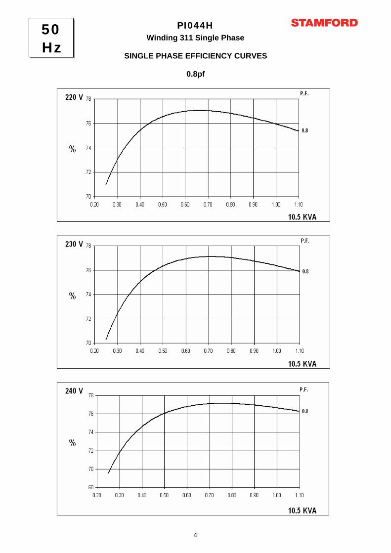
0.8pf
PI044HWinding 311 Single Phase
SINGLE PHASE EFFICIENCY CURVES
50Hz
4
AP
PR
OV
ED
DO
CU
ME
NT
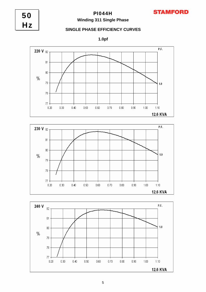
PI044HWinding 311 Single Phase
SINGLE PHASE EFFICIENCY CURVES
1.0pf
50Hz
5
AP
PR
OV
ED
DO
CU
ME
NT
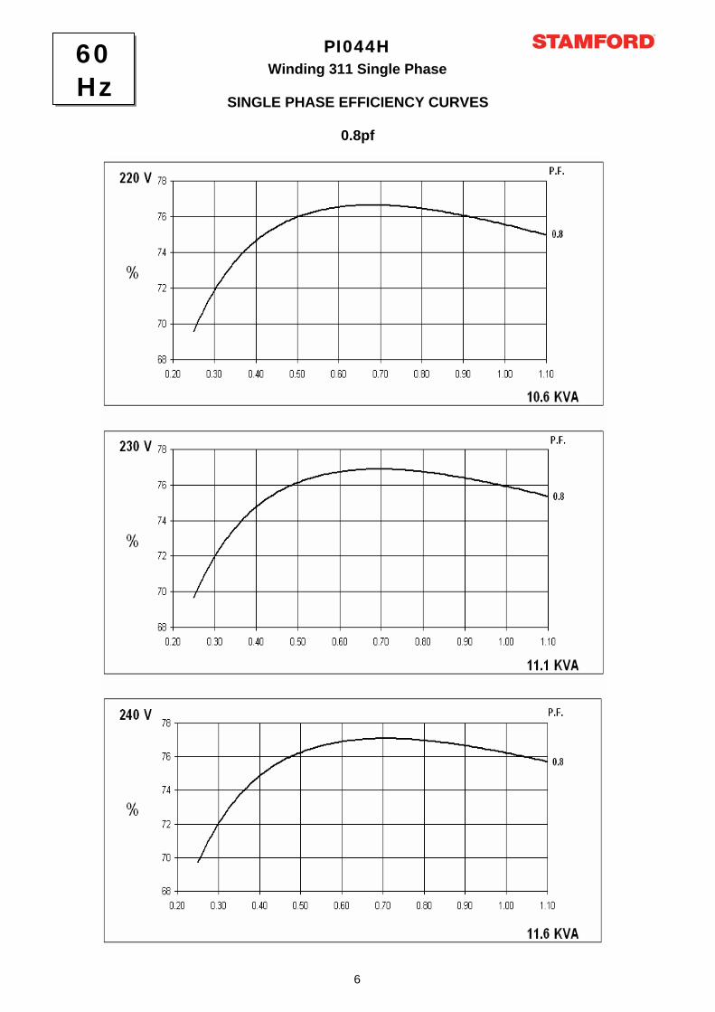
PI044HWinding 311 Single Phase
SINGLE PHASE EFFICIENCY CURVES
0.8pf
60Hz
6

AP
PR
OV
ED
DO
CU
ME
NT
PI044HWinding 311 Single Phase
SINGLE PHASE EFFICIENCY CURVES
1.0pf
60Hz
7
AP
PR
OV
ED
DO
CU
ME
NT
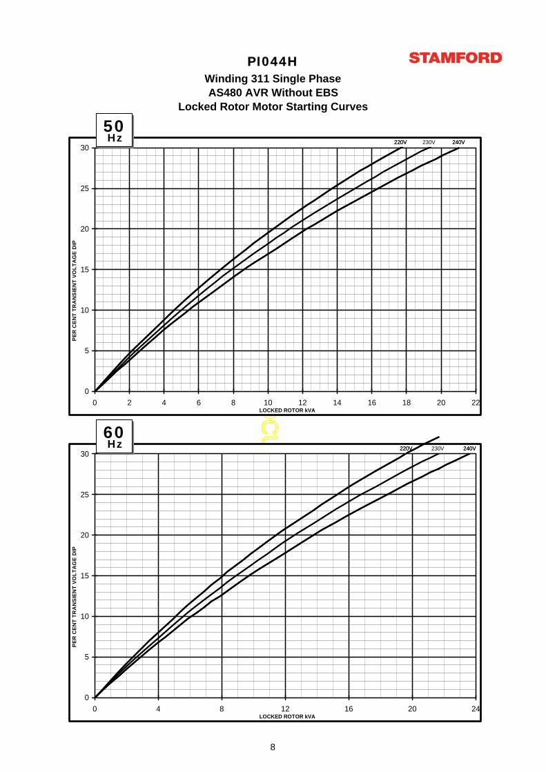
PI044HWinding 311 Single Phase
Locked Rotor Motor Starting CurvesAS480 AVR Without EBS
220V220V 230V 240V240V
0
5
10
15
20
25
30
0 2 4 6 8 10 12 14 16 18 20 22LOCKED ROTOR kVA
PER
CEN
T TR
AN
SIEN
T VO
LTA
GE
DIP
.
220V220V 230V 240V240V
0
5
10
15
20
25
30
0 4 8 12 16 20 24LOCKED ROTOR kVA
PER
CEN
T TR
AN
SIEN
T VO
LTA
GE
DIP
.
50Hz
60Hz
8
AP
PR
OV
ED
DO
CU
ME
NT
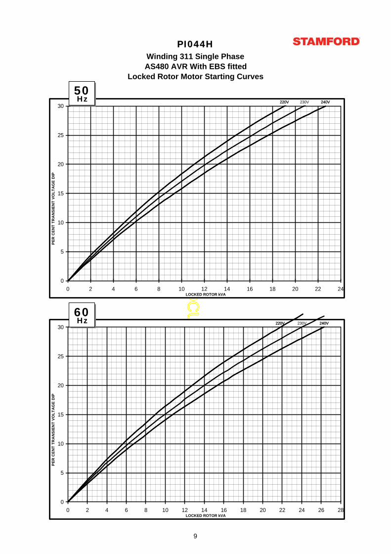
PI044HWinding 311 Single Phase
Locked Rotor Motor Starting CurvesAS480 AVR With EBS fitted
220V220V 230V 240V240V
0
5
10
15
20
25
30
0 2 4 6 8 10 12 14 16 18 20 22 24LOCKED ROTOR kVA
PER
CEN
T TR
AN
SIEN
T VO
LTA
GE
DIP
.
220V220V 230V 240V240V
0
5
10
15
20
25
30
0 2 4 6 8 10 12 14 16 18 20 22 24 26 28LOCKED ROTOR kVA
PER
CEN
T TR
AN
SIEN
T VO
LTA
GE
DIP
.
50Hz
60Hz
9
AP
PR
OV
ED
DO
CU
ME
NT
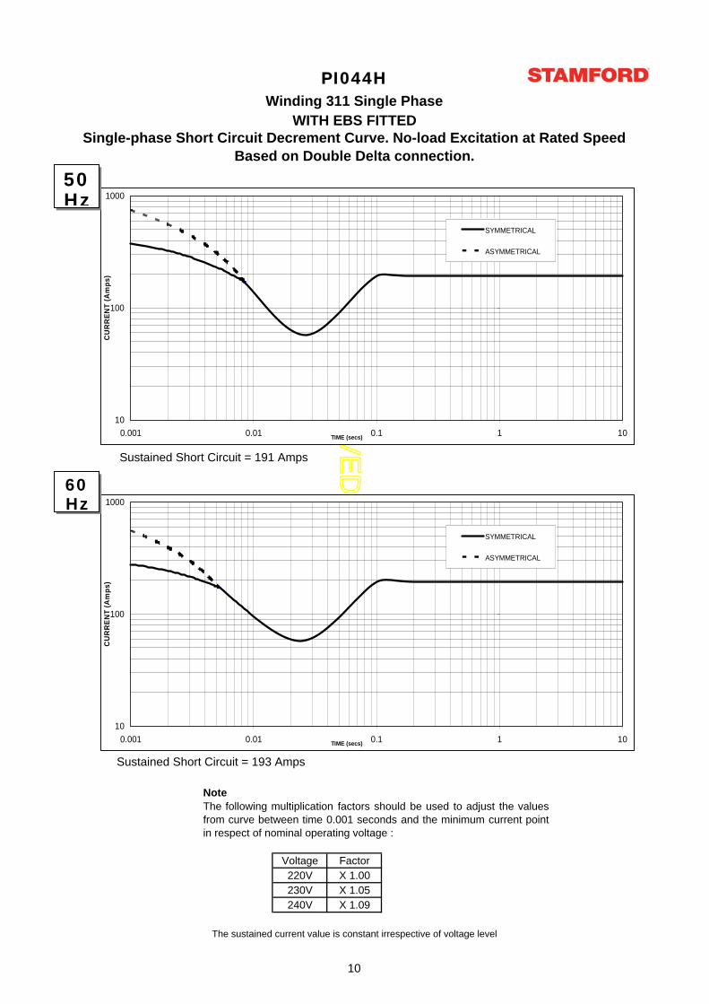
Voltage Factor220V X 1.00230V X 1.05240V X 1.09
Single-phase Short Circuit Decrement Curve. No-load Excitation at Rated SpeedBased on Double Delta connection.
The sustained current value is constant irrespective of voltage level
PI044H
WITH EBS FITTEDWinding 311 Single Phase
Sustained Short Circuit = 191 Amps
Sustained Short Circuit = 193 Amps
Note The following multiplication factors should be used to adjust the valuesfrom curve between time 0.001 seconds and the minimum current pointin respect of nominal operating voltage :
10
100
1000
0.001 0.01 0.1 1 10TIME (secs)
CU
RR
ENT
(Am
ps)
SYMMETRICAL
ASYMMETRICAL
10
100
1000
0.001 0.01 0.1 1 10TIME (secs)
CU
RR
ENT
(Am
ps)
SYMMETRICAL
ASYMMETRICAL
50Hz
60Hz
10
AP
PR
OV
ED
DO
CU
ME
NT
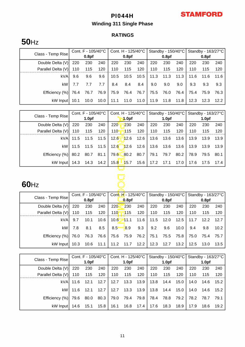
Class - Temp Rise
Double Delta (V) 220 230 240 220 230 240 220 230 240 220 230 240Parallel Delta (V) 110 115 120 110 115 120 110 115 120 110 115 120
kVA 9.6 9.6 9.6 10.5 10.5 10.5 11.3 11.3 11.3 11.6 11.6 11.6
kW 7.7 7.7 7.7 8.4 8.4 8.4 9.0 9.0 9.0 9.3 9.3 9.3
Efficiency (%) 76.4 76.7 76.9 75.9 76.4 76.7 75.5 76.0 76.4 75.4 75.9 76.3
kW Input 10.1 10.0 10.0 11.1 11.0 11.0 11.9 11.8 11.8 12.3 12.3 12.2
Class - Temp Rise
Double Delta (V) 220 230 240 220 230 240 220 230 240 220 230 240Parallel Delta (V) 110 115 120 110 115 120 110 115 120 110 115 120
kVA 11.5 11.5 11.5 12.6 12.6 12.6 13.6 13.6 13.6 13.9 13.9 13.9
kW 11.5 11.5 11.5 12.6 12.6 12.6 13.6 13.6 13.6 13.9 13.9 13.9
Efficiency (%) 80.2 80.7 81.1 79.6 80.2 80.7 79.1 79.7 80.2 78.9 79.5 80.1
kW Input 14.3 14.3 14.2 15.8 15.7 15.6 17.2 17.1 17.0 17.6 17.5 17.4
Class - Temp Rise
Double Delta (V) 220 230 240 220 230 240 220 230 240 220 230 240Parallel Delta (V) 110 115 120 110 115 120 110 115 120 110 115 120
kVA 9.7 10.1 10.6 10.6 11.1 11.6 11.5 12.0 12.5 11.7 12.2 12.7
kW 7.8 8.1 8.5 8.5 8.9 9.3 9.2 9.6 10.0 9.4 9.8 10.2
Efficiency (%) 76.0 76.3 76.6 75.6 75.9 76.2 75.1 75.5 75.8 75.0 75.4 75.7
kW Input 10.3 10.6 11.1 11.2 11.7 12.2 12.3 12.7 13.2 12.5 13.0 13.5
Class - Temp Rise
Double Delta (V) 220 230 240 220 230 240 220 230 240 220 230 240Parallel Delta (V) 110 115 120 110 115 120 110 115 120 110 115 120
kVA 11.6 12.1 12.7 12.7 13.3 13.9 13.8 14.4 15.0 14.0 14.6 15.2
kW 11.6 12.1 12.7 12.7 13.3 13.9 13.8 14.4 15.0 14.0 14.6 15.2
Efficiency (%) 79.6 80.0 80.3 79.0 79.4 79.8 78.4 78.8 79.2 78.2 78.7 79.1
kW Input 14.6 15.1 15.8 16.1 16.8 17.4 17.6 18.3 18.9 17.9 18.6 19.2
Cont. F - 105/40°C 1.0pf
Cont. H - 125/40°C 1.0pf
Standby - 150/40°C 1.0pf
Standby - 163/27°C 1.0pf
Cont. F - 105/40°C 0.8pf
Cont. H - 125/40°C 0.8pf
Standby - 150/40°C 0.8pf
Standby - 163/27°C 0.8pf
Cont. F - 105/40°C 1.0pf
Cont. H - 125/40°C 1.0pf
Standby - 150/40°C 1.0pf
Standby - 163/27°C 1.0pf
PI044HWinding 311 Single Phase
RATINGS
Cont. F - 105/40°C 0.8pf
Cont. H - 125/40°C 0.8pf
Standby - 150/40°C 0.8pf
Standby - 163/27°C 0.8pf
50Hz
60Hz
11

AP
PR
OV
ED
DO
CU
ME
NT
DIMENSIONS
PI044HWinding 311 Single Phase
12

AP
PR
OV
ED
DO
CU
ME
NT
PI044H-311-1P-TD-EN-SG-A
Head Office Address:Barnack Road, StamfordLincolnshire, PE9 2NB
United KingdomTel: +44 (0) 1780 484000Fax: +44 (0) 1780 484100
www.cumminsgeneratortechnologies.com
Copyright 2010, Cummins Generator Technologies Ltd, All Rights ReservedStamford and AvK are registered trade marks of Cummins Generator Technologies Ltd
Cummins and the Cummins logo are registered trade marks of Cummins Inc.
Recommended