LSCO. Report No. 2123-3.0-4-1
-
TECHNOLOGY TRANSFER PROGRAM (TTP)
F I N A L R E P O R T
PLANNING AND PRODUCTION CONTROL SYSTEM
0029
PLANNING & PRODUCTION CONTROL
VOLUME 1 REPORT
Prepared by:
Livingston Shipbuilding Companyin conjunction with:IHI Marine Technology Inc. November 24, 1980

Report Documentation Page Form ApprovedOMB No. 0704-0188
Public reporting burden for the collection of information is estimated to average 1 hour per response, including the time for reviewing instructions, searching existing data sources, gathering andmaintaining the data needed, and completing and reviewing the collection of information. Send comments regarding this burden estimate or any other aspect of this collection of information,including suggestions for reducing this burden, to Washington Headquarters Services, Directorate for Information Operations and Reports, 1215 Jefferson Davis Highway, Suite 1204, ArlingtonVA 22202-4302. Respondents should be aware that notwithstanding any other provision of law, no person shall be subject to a penalty for failing to comply with a collection of information if itdoes not display a currently valid OMB control number.
1. REPORT DATE 24 NOV 1980
2. REPORT TYPE N/A
3. DATES COVERED -
4. TITLE AND SUBTITLE Technology Transfer Program (TTP) Planning & Production ControlVolume 1 Report
5a. CONTRACT NUMBER
5b. GRANT NUMBER
5c. PROGRAM ELEMENT NUMBER
6. AUTHOR(S) 5d. PROJECT NUMBER
5e. TASK NUMBER
5f. WORK UNIT NUMBER
7. PERFORMING ORGANIZATION NAME(S) AND ADDRESS(ES) Naval Surface Warfare Center CD Code 2230 - Design Integration ToolsBuilding 192 Room 128-9500 MacArthur Blvd Bethesda, MD 20817-5700
8. PERFORMING ORGANIZATIONREPORT NUMBER
9. SPONSORING/MONITORING AGENCY NAME(S) AND ADDRESS(ES) 10. SPONSOR/MONITOR’S ACRONYM(S)
11. SPONSOR/MONITOR’S REPORT NUMBER(S)
12. DISTRIBUTION/AVAILABILITY STATEMENT Approved for public release, distribution unlimited
13. SUPPLEMENTARY NOTES
14. ABSTRACT
15. SUBJECT TERMS
16. SECURITY CLASSIFICATION OF: 17. LIMITATION OF ABSTRACT
SAR
18. NUMBEROF PAGES
229
19a. NAME OFRESPONSIBLE PERSON
a. REPORT unclassified
b. ABSTRACT unclassified
c. THIS PAGE unclassified
Standard Form 298 (Rev. 8-98) Prescribed by ANSI Std Z39-18

ACKNOWLEDGEMENTS
Livingston gratefully acknowledges the generous
contributions of the IHI Consulting Personnel and
all of the IHI personnel in Japan who made this
study possible.
Yukinori Mikami,
Mr. O. Togo, Mr.
Yukinawa, Mr. H.
Special appreciation is due Mr.
Mr. H. Kurose, Mr. T. Yamamoto,
K. Chikara, Mr. S. Sato, Mr. T.
Akamatsu, Mr. K. Honda, and Mr.
I. Kanazawa whose patience and persistence enabled
us to understand the IHI concepts presented herein.

PREFACE
This report is one of several emanating from the Shipbuilding
Technology Transfer program performed by Livingston Shipbuilding
Company under a cost-sharing contract with the U.S. Maritime Adminis-
tration.
The material contained herein was developed from the study of the
Planning & Production Control systems presently in operation in the
shipyards of Ishikawajima-Harima Heavy Industries (IHI) of Japan.
Information for this study was derived from source documentation
supplied by IHI, information obtained directly from IHI consulting
personnel assigned on-site at Levingston, and from personal observa-
tions by two teams of Livingston personnel of actual operations at
various IHI shipyards in Japan.
In order to place this study in context within the overall Tech-
nology Transfer Program, a brief overview of the program and its
organization is provided in the following paragraphs.
THE TECHNOLOGY TRANSFER PROGRAM (TTP)
The U.S. shipbuilding industry is well aware of the significant
shipbuilding cost differences between the Japanese and ourselves.
Many reasons have been offered to explain this differential and
whether the reasons are valid or not, the fact remains that Japanese
yards are consistently able to offer ships at a price of one-half to
two-thirds below the U.S. prices.
Seeing this tremendous difference first hand in their own estimate
of a bulk carrier slightly modified from the IHI “Future-32” class de-
sign, Livingston management determined not only to find out why this was
i
true but also to attempt to determine precise differences between IHI
and Livingston engineering and design practices; production planning
and control methods; facilites, production processes, methods and
techniques; quality assurance methods; and personnel organization,
operations and training. The obvious objective of such studies was to
identify, examine and implement the Japanese systems, methods and pro-
cesses which promised a significant improvement in the Livingston
design/production process.
With this objective in mind, and recognizing the potential appli-
cation of the TTP results to the American shipbuilding industry,
Livingston initiated a cost-sharing contract with MarAd to provide
documentation and industry seminars to reveal program findings and
production improvement results measured during production of the
bulkers. At the same time, Livingston subcontracted with IHI Marine
Technology Inc. (an American corporation and a subsidiary of IHI,
Japan) specifying the areas to be explored and the number and type of
IHI consulting personnel required during the period of re-design and
initial construction of the first bulker.
Basically, the program is organized into six major tasks:
1 - Cost Accounting
2 - Engineering and Design
3 - Planning and Production Control
4 - Facilities and Industrial Engineering
5 - Quality Assurance
6 - Industrial Relations
Beneath each of these major tasks is a series of sub-tasks which
ii

further delineate discrete areas of investigation and study. Each sub-
task area has been planned and scheduled to: 1) study IHI systems,
methods and techniques; 2) compare the Livingston and IHI practices;
3) identify improvements to the Livingston systems; 4) implement
approved changes; 5) document program findings, changes to the
Livingston systems, and the results of those changes; and 6) dissem-
inate program findings and results to industry via MarAd.
iii

SECTION PARAGRAPH
3.2.3
3.2.3.1
3.2.3.1.1
3.2.3.1.2
3.2.3.2
3.2.3.2.1
3.2.3.2.2
3.2.3.2.3
3.2.3.2.4
3.2.3.2.5
3.2.3.2.6
3.2.3.3
3.2.3.3.1
3.2.3.3.2
3.2.3.3.3
3.2.3.3.4
3.2.3.3.5
3.3
3.3.1
3.3.2
TABLE OF CONTENTS
TITLE
(CONT.)
Working Instruction Plans
Working Instruction Plans forFabrication
Cutting Plans
Bending Plans
Working Instruction Plan forSub-assembly and Assembly
Block Parts List
PAGE NO.
3-14
3--17
3-17
3-19
3-24
3-24
Block Lifting Instructions Plan 3-24
Working Instruction Plan forSub-assembly
Working Instruction Plan forAssembly
Finishing Dimensions Plan
Assembly Jig Arrangement Plan
Working Instruction Plans forErection
Hull Blocking Plans
Shipwright Dimensions Plans
Supporting Block ArrangementPlans
Welding Process InstructionPlans
Scaffolding Arrangement Plan
Outfit Planning
Design
Procurement
3-26
3-26
3-26
3-35
3-35
3-35
3-37
3-37
3-37
3-41
3-41
3-45
3-60
v


TABLE OF CONTENTS (CONT.)
SECTION PARAGRAPH
7.2.3.2
7.2.3.3
7.3
7.4
7.5
7.6
8.1
8.2
8.3
8.4
TITLE
Basic Production Flow List
Unit Information List
Outfit Planning
Schedules
Manpower Planning and PerformanceMeasurement
Current Livingston Application
APPLICATION TO U.S. SHIPBUILDING
General
Hull Construction
Outfitting
Conclusion
VOLUME II - APPENDICES
Glossary of Terms
Product-Oriented Work BreakdownStructure
Hull Blocking Plan
Block Assembly Plan
Field Plans
Gate System Implementation
PAGE NO.
7-13
7-13
7-16
7-20
7-20
7-24
8-1
8-3
8-4
8-6
A-1
B-1
c-1
D-1
E-1
F-1
viii
LIST OF ILLUSTRATIONS
FIGUREN O .
2-1
2-2
2-3
2-4
2-5
2-6
2-7
2-8
2-9
2-10
2-11
3-1
3-2
3-3
3-4
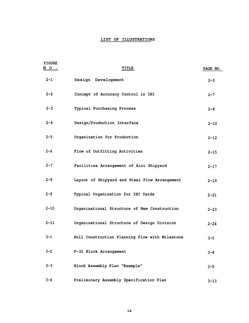
TITLE
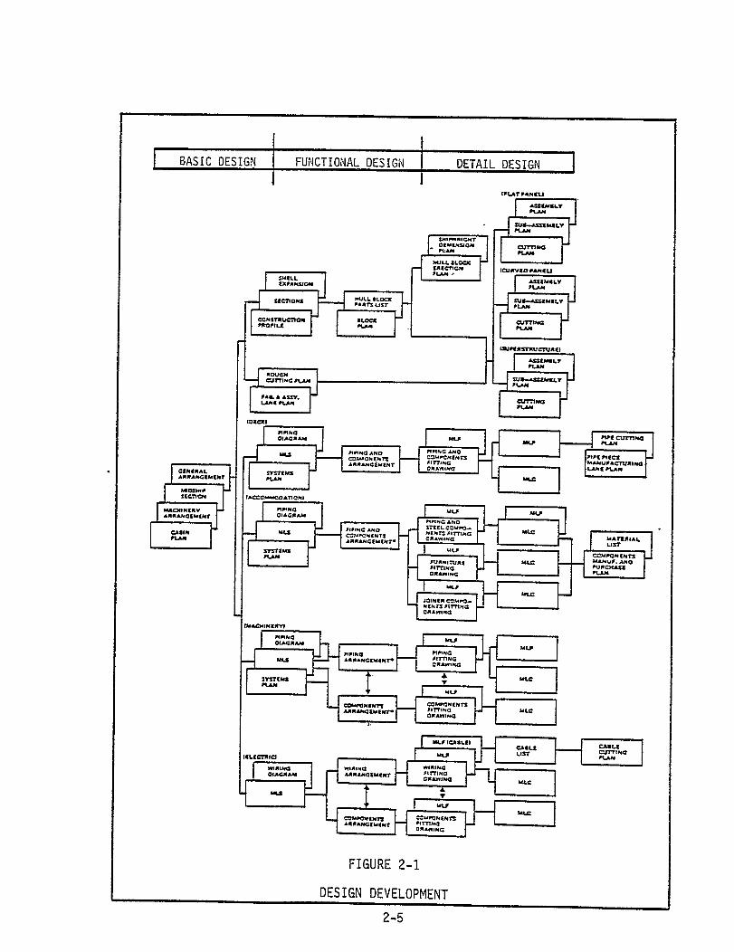
Design Development
Concept of Accuracy Control in IHI
Typical Purchasing Process
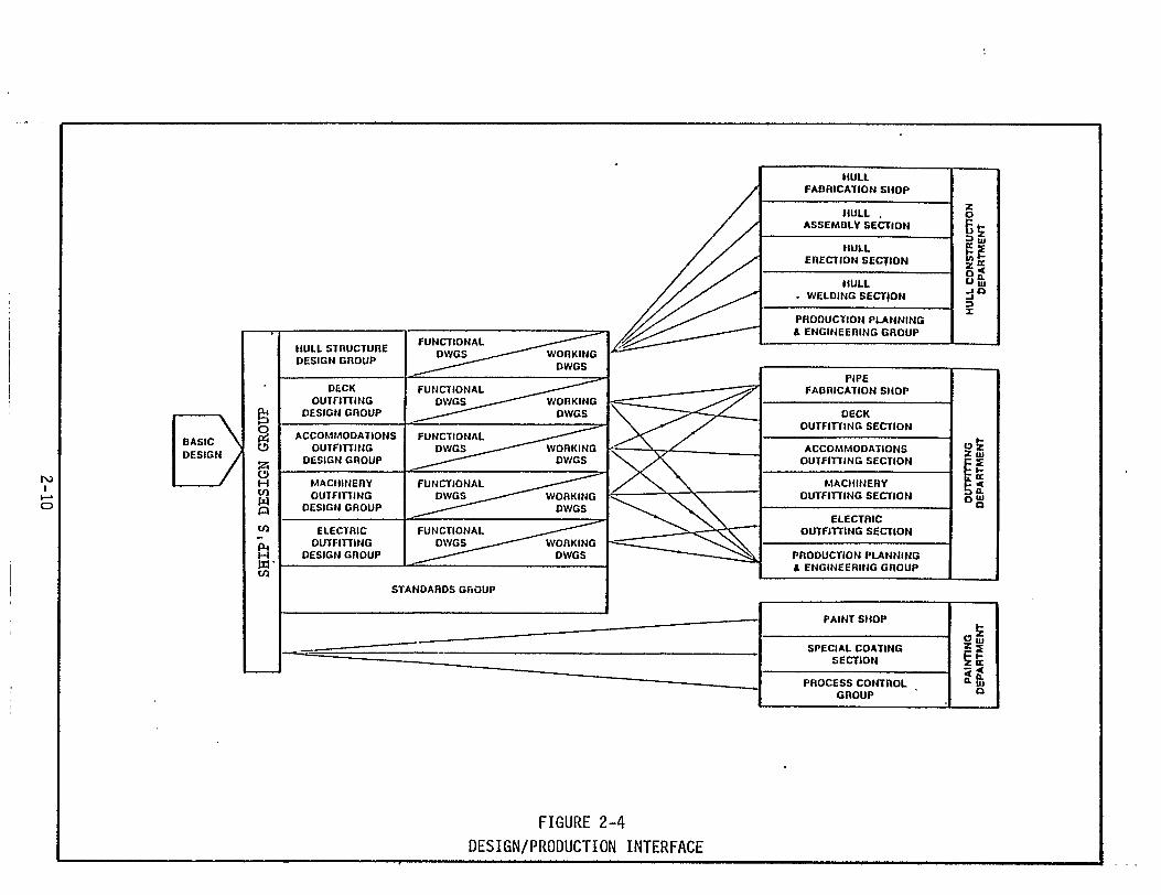
Design/Production Interface
Organization for Production
Flow of Outfitting Activities
Facilities Arrangement of Aioi Shipyard
Layout of Shipyard and Steel Flow Arrangement
Typical Organization for IHI Yards
Organizational Structure of New Construction
Organizational Structure of Design Division
Hull Construction Planning Flow with Milestone
F-32 Block Arrangement
Block Assembly Plan "Example"
Preliminary Assembly Specification Plan
ix
PAGE NO.
2-5
2-7
2-8
2-10
2-12
2-15
2-17
2-19
2-21
2-23
2-24
3-5
3-8
3-9
3-13
LIST OF ILLUSTRATIONS
FIGURENO.
3-!5
3-6
3-7
3-8
3-9
3-10
3-11
3-12
3-13
3-14
3-15
3-16
3-17
3-18
3-19
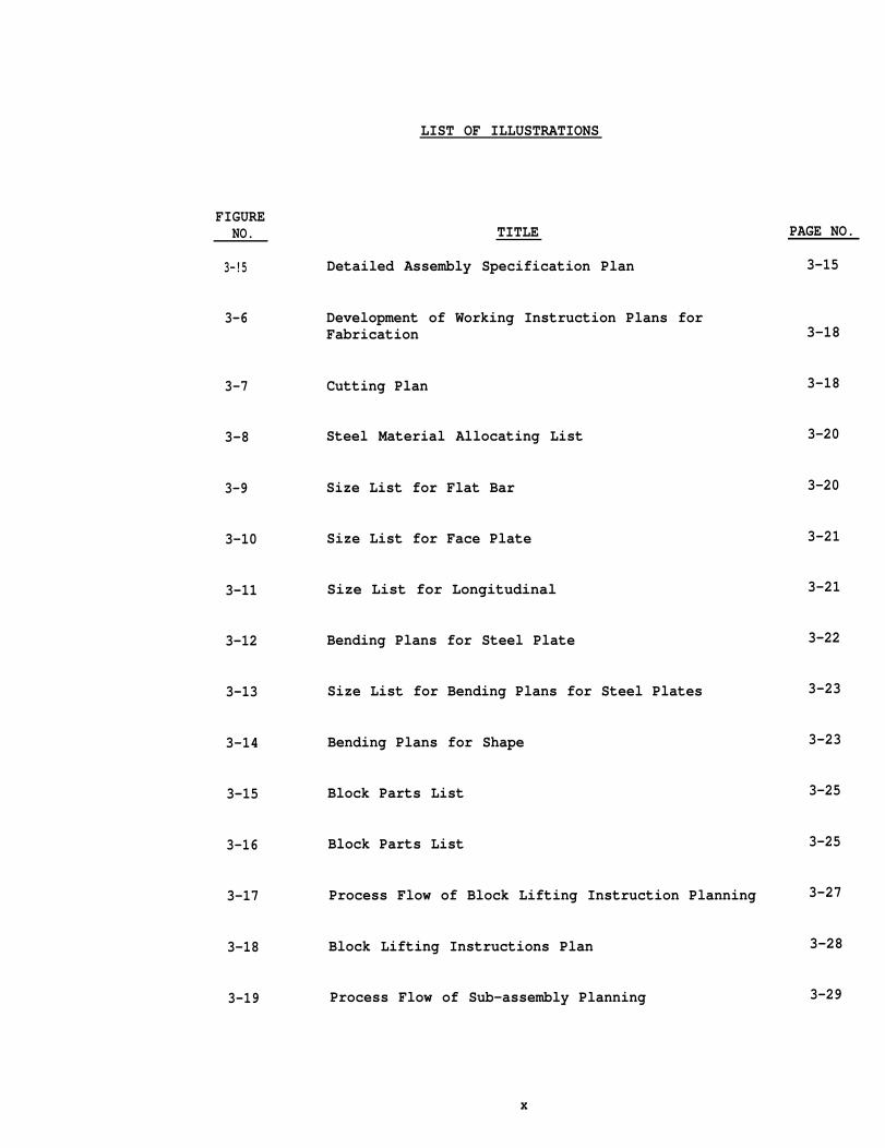
TITLE
Detailed Assembly Specification Plan
Development of Working Instruction Plans forFabrication
Cutting Plan
Steel Material Allocating List
Size List for Flat Bar
Size List for Face Plate
Size List for Longitudinal
Bending Plans for Steel Plate
Size List for Bending Plans for Steel Plates
Bending Plans for Shape
Block Parts List
Block Parts List
Process Flow of Block Lifting Instruction Planning
Block Lifting Instructions Plan
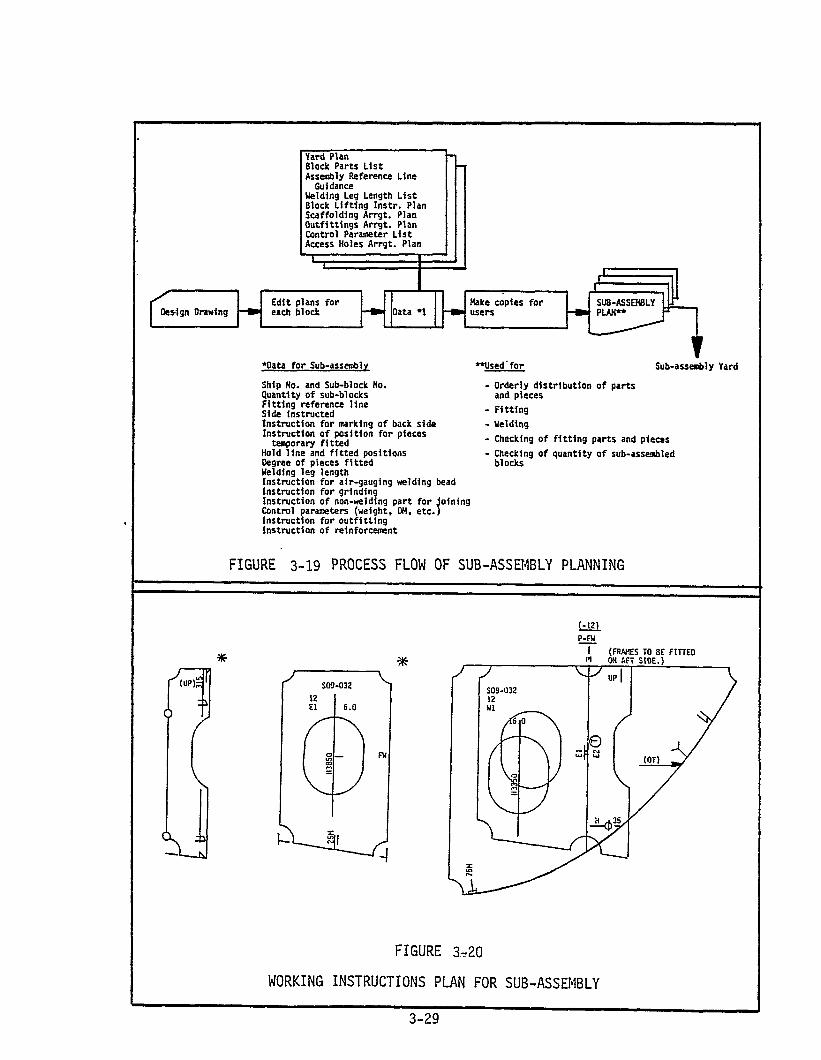
Process Flow of Sub-assembly Planning
PAGE NO.
3-15
3-18
3-18
3-20
3-20
3-21
3-21
3-22
3-23
3-23
3-25
3-25
3-27
3-28
3-29
x
LIST OF ILLUSTRATIONS
FIGURENO.
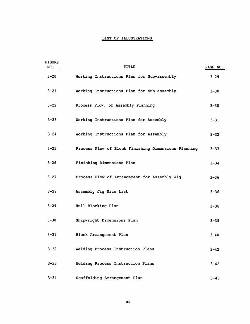
3-20
3-21
3-22
3-23
3-24
3-25
3-26
3-27
3-28
3-29
3-30
3-31
3-32
3-33
3-34
TITLE
Working Instructions Plan for Sub-assembly
Working Instructions Plan for Sub-assembly
Process Flow. of Assembly Planning
Working Instructions Plan for Assembly
Working Instructions Plan for Assembly
Process Flow of Block Finishing Dimensions Planning
Finishing Dimensions Plan
Process Flow of Arrangement for Assembly Jig
Assembly Jig Size List
Hull Blocking Plan
Shipwright Dimensions Plan
Block Arrangement Plan
Welding Process Instruction Plans
Welding Process Instruction Plans
Scaffolding Arrangement Plan
PAGE NO.
3-29
3-30
3-30
3-31
3-32
3-33
3-34
3-36
3-36
3-38
3-39
3-40
3-42
3-42
3-43
xi

LIST OF ILLUSTRATIONS
FIGURENO.
3-35
3-36
3-37
3-38
3-39
3-40
3-40(Cont. )
3-41
3-42
3-43
3-44
3-45
3-46
3-47
3-48
TITLE
Outline of Scaffolding Facilities
Flow of Outfitting
Material List by System
Different Ship Zones
Outfitting Zones
Material List for
Material List for
Composite Drawing
Outfitting Design
Pipe (MLP)
Component (MLc)
Development
Work Instruction Drawing
Material List for Fitting (MLF)
Procurement Information Flow
Functional Flow of Material and Requisition
Purchasing Process
Functional Flow of the Subcontracting Process
PAGE NO.
3-44
3-46
3-48
3-49
3-51
3-53
3-54
3-55
3-57
3-58
3-59
3-61
3-62
3-63
3-64
xii

LIST OF ILLUSTRATIONS
FIGURENO.
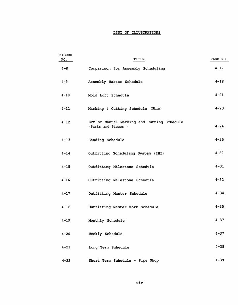
4-8
4-9
4-10
4-11
4-12
4-13
4-14
4-15
4-16
4-17
4-18
4-19
4-20
4-21
4-22
TITLE
Comparison for Assembly Scheduling
Assembly Master Schedule
Mold Loft Schedule
Marking & Cutting Schedule (Skin)
EPM or Manual Marking and Cutting Schedule(Parts and Pieces )
Bending Schedule
Outfitting Scheduling System (IHI)
Outfitting Milestone Schedule
Outfitting Milestone Schedule
Outfitting Master Schedule
Outfitting Master Work Schedule
Monthly Schedule
Weekly Schedule
Long Term Schedule
Short Term Schedule - Pipe Shop
PAGE NO.
4-17
4-18
4-21
4-23
4-24
4-25
4-29
4-31
4-32
4-34
4-35
4-37
4-37
4-38
4-39
xiv
LIST OF ILLUSTRATIONS
F I G U R ENO. TITLE PAGE NO.
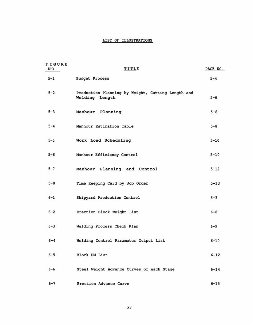
5-1 Budget Process 5-4
5-2 Production Planning by Weight, Cutting Length andWelding Length 5-6
5-3 Manhour Planning 5-8
5-4 Manhour Estimation Table 5-8
5-5 Work Load Scheduling 5-10
5-6 Manhour Efficiency Control 5-10
5-7 Manhour Planning and Control 5-12
5-8 Time Keeping Card by Job Order 5-13
6-1 Shipyard Production Control 6-3
6-2 Erection Block Weight List 6-8
6-3 Welding Process Check Plan 6-9
6-4 Welding Control Parameter Output List 6-10
6-5 Block DM List 6-12
6-6 Steel Weight Advance Curves of each Stage 6-14
6-7 Erection Advance Curve 6-15
xv

LIST OF ILLUSTRATIONS
F U EN O .
6-8
6-9
6-10
7-1
7-2
7-2(Cont.)
7-3
7-4
7-5
7-6
7-7
7-8
7-9
7-10
7-11
T I TLE
Outfitting Scheduling System [IHI)
On-Board Piping Schedule in Engine Room
Performance Control Chart
Gate System
Livingston Yard Layout
Material Flow
Basic Method of Planning and Scheduling
Key Erection Plan
Key Erection Times List
Basic Production Flow List
Unit Information List
Material Information List
Final Assembly Master Schedule
Unit to Unit Master Schedule
Component Assembly Master Schedule
PAGE NO.
6-17
6-19
6-19
7-7
7-9
7-10
7-11
7-12
7-14
7-15
7-17
7-18
7-21
7-21
7-22
xvi

FIGURE
7-12
7-13
7-14
7-15
T3-1
T4- 1
T6-1
T7- 1
LIST OF ILLUSTRATIONS
TITLE
Panel Line Master Schedule
Long Term Gate Schedule
Short Term Gate Schedule
LSCO. Planning and Scheduling Flow
LIST OF TABLES
Plans for Production
Typical Milestone List
Hull Construction Control Graphs
Planning and Control Techniques Adopted byLivingston
xvi i
PAGE NO.
7-22
7-23
7-23
7-27
3-3
4-31
6-6
7-25
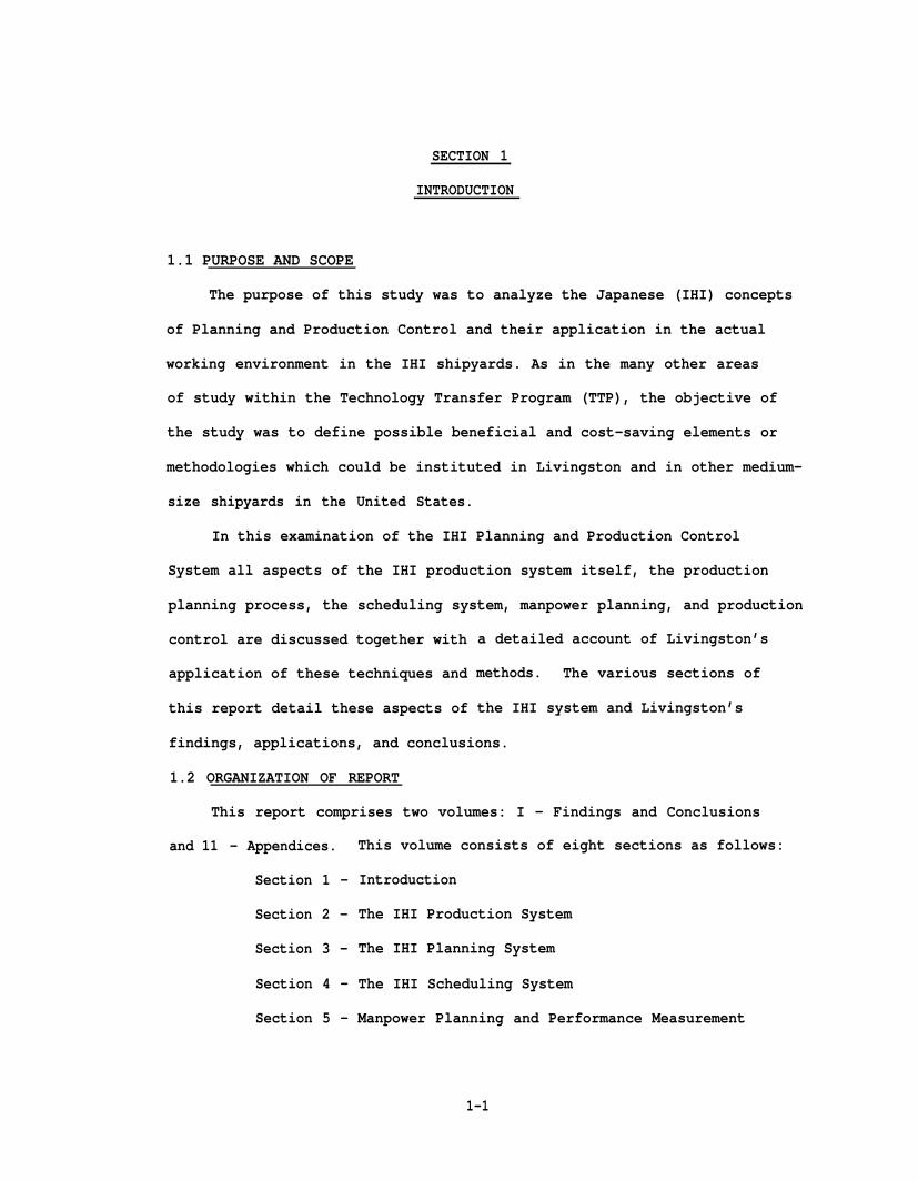
SECTION 1
INTRODUCTION
1.1 PURPOSE AND SCOPE
The purpose of this study was to analyze the Japanese (IHI) concepts
of Planning and Production Control and their application in the actual
working environment in the IHI shipyards. As in the many other areas
of study within the Technology Transfer Program (TTP), the objective of
the study was to define possible beneficial and cost-saving elements or
methodologies which could be instituted in Livingston and in other medium-
size shipyards in the United States.
In this examination of the IHI Planning and Production Control
System all aspects of the IHI production system itself, the production
planning process, the scheduling system, manpower planning, and production
control are discussed together with
application of these techniques and
this report detail these aspects of
a detailed account of Livingston’s
methods. The various sections of
the IHI system and Livingston’s
findings, applications, and conclusions.
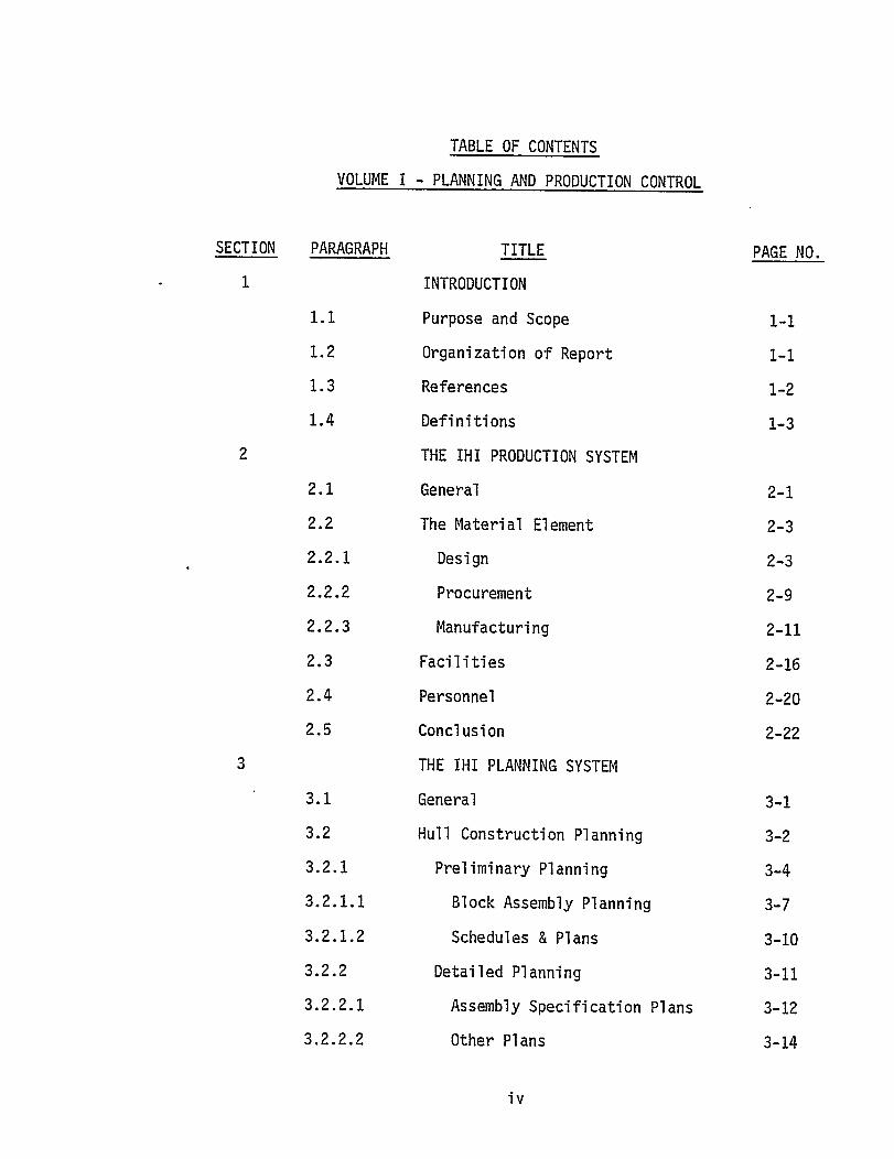
1.2 ORGANIZATION OF REPORT
This report comprises two volumes: I - Findings and Conclusions
and 11 - Appendices.
Section 1 -
Section 2 -
Section 3 -
Section 4 -
Section 5 -
This volume consists of eight sections as follows:
Introduction
The IHI Production System
The IHI Planning System
The IHI Scheduling System
Manpower Planning and Performance Measurement
1-1

Section 6 - Production Control
Section 7 - Livingston Application of IHI Technology
Section 8 - Application to U.S. Shipbuilding
Sections 2 through 6 detail the IHI production and production plan-
ning and control methods, whereas Sections 7 and 8 serve to synthesize
these data for application to U.S. shipyards.
A series of appendices are also included in Volume II of this
report as an adjunct to the findings and conclusions presented herein.
These appendices comprise data provided by IHI in the course of this
program. The appendices are listed below.
Appendix A - Glossary of Terms
Appendix B - Product-Oriented Work Breakdown Structure
Appendix C - Hull Blocking Plan
Appendix D - Block Assembly Plan
Appendix E - Field Plans
Appendix F - Gate System Implementation
1.3 REFERENCES
Throughout this report reference is made to other reports some of
which were produced by Livingston, resulting from the Technology Transfer
Program. A list of these reports is presented below.
REPORT
Final Report - Quality Assurance (LSCO. )
Final Report - Industrial Relations (LSCO.)
Special Report - Accuracy Control P1 arming ( LSCO. )
Report - Outfit Planning (Todd)
REPORT NO. DATE IS
2123-5.1-4-1 3/3/80
2123-6.1-4-1 3/28/80
2123-5.1-4-2 3/15/80
12/79
1-2

1.4 DEFINITIONS
Throughout this
sections of the ship
to form the complete
report several terms
which are ultimately
are used to denote fabricated
erected in a building basin
ship structure. These terms have specific meanings
within the context of the Japanese ship construction methodology. Al-
though a more thorough Glossary of Terms is provided in Appendix A to
this report, it is necessary to define certain of these terms in ad-
vance of the text to provide some clarification of the material for the
reader.
ASSEMBLY - (Noun) A composite of fabricated parts and pieces
assembled and affixed to form a whole element which will be installed
as an entity in a larger assembly or in the ship under construction.
UNIT - A defined segment of the ship’s structure capable of being
individually constructed, handled, transported, lifted and landed as
an entity aboard the ship under construction.
BLOCK - Japanese term for unit.
NOTE: In the following discussion the terms Unit and Block
are used interchangeably, however, the term Block is
used only to refer to formal IHI planning documents
and techniques.
(e.g. Hull Block Planning)
1-3

SECTION 2
THE IHI PRODUCTION SYSTEM
2.1 GENERAL
The IHI Production System is a well designed and highly integrated
composite of material, facilities and personnel. It comprises a series
of sub-systems which, although they can be described as independent
elements, are interwoven to form a functional whole capable of efficient
operation at each stage of design and production and at every level of
the organization.
The basic and total orientation of the IHI shipyards is toward the
production of high-quality products at the least possible cost and
every aspect of the production process has been refined and perfected
over a number of years to serve this production objective. As a
result of this system refinement and integration it is impossible to
separate clearly each of the elements of the production system without
at least a cursory understanding of the whole process. For example,
to understand the Planning and Production Control function it is
necessary to relate it to the basic shipyard organization, to the
production system itself, to the activities of the Design Department
and to the functions of Accuracy Control and Quality Control. TO
take any one element out of the context of the whole system is to
deny any real understanding of the IHI production methodology. There-’
fore, to enable a better understanding of the subject of this report,
a general overview of the IHI Production System is presented in the
following pages.
2-1

It is possible to describe the IHI Production System in several
ways: chronologically, by discrete functions, by organization, by
process stages, etc. There are, however, inevitable distortions of
the real situation inherent in any written description of such a com-
plex subject. Also, one of the intrinsic characteristics of the IHI
system is flexibility, which further limits the ability of any docu-
mentation to portray accurately the absolute functioning and methods
of the IHI yards. Each yard superintendent is given some latitude in
the implementation of the production system methodology but the essen-
tial elements of the system are preserved in each yard, regardless of
minor deviations.
The essential elements of the system concern the three basic
ingredients of any manufacturing enterprise: material, facilities
and personnel. Each of these basic elements is subdivided into the
functions, processes or arrangements necessary to provide the infor-
mation, hardware and people requisite to the
of the operation.
The following paragraphs describe these
and the various subdivisions of each to famil
the total system. This breakdown into mater
personnel is not intended to define specific
relationships nor the time-sequencing of the
chronological sequence
major system elements
iarize the reader with
al, facilities and
organizations, inter-
activities of the various
subdivisions. Rather, it is intended simply as an overview of how
the three major elements are structured in the total IHI production
system. The description of the integrated functioning of these
2-2
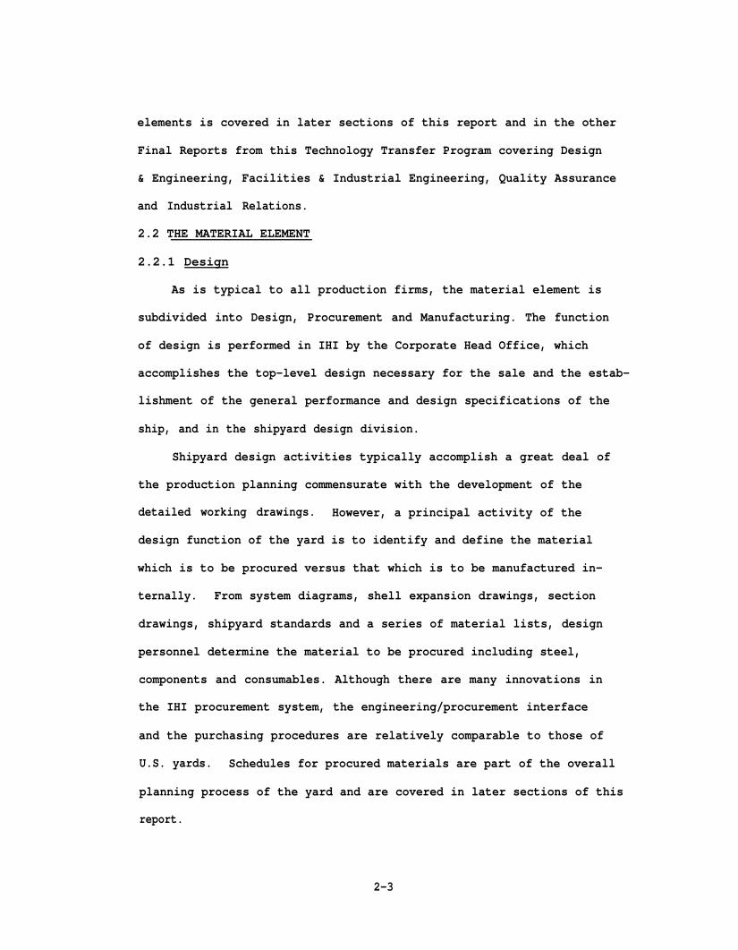
elements is covered in later sections of this report and in the other
Final Reports from this Technology Transfer Program covering Design
& Engineering, Facilities & Industrial Engineering, Quality Assurance
and Industrial Relations.
2.2 THE MATERIAL ELEMENT
2.2.1 Design
As is typical to all production firms, the material element is
subdivided into Design, Procurement and Manufacturing. The function
of design is performed in IHI by the Corporate Head Office, which
accomplishes the top-level design necessary for the sale and the estab-
lishment of the general performance and design specifications of the
ship, and in the shipyard design division.
Shipyard design activities typically accomplish a great deal of
the production planning commensurate with the development of the
detailed working drawings. However, a principal activity of the
design function of the yard is to identify and define the material
which is to be procured versus that which is to be manufactured in-
ternally. From system diagrams, shell expansion drawings, section
drawings, shipyard standards and a series of material lists, design
personnel determine the material to be procured including steel,
components and consumables. Although there are many innovations in
the IHI procurement system, the engineering/procurement interface
and the purchasing procedures are relatively comparable to those of
U.S. yards. Schedules for procured materials are part of the overall
planning process of the yard and are covered in later sections of this
report.
2-3

The design for manufacture is the primary function of the yard
design division. From the top-level drawings and specifications, the
details of the ship are progressively developed to the lowest level
necessary for the fabrication of parts and pieces, sub-assembly of
individual components (both hull parts and outfitting parts), assembly
of hull units and final erection of these units on the ways. Figure
2-1 portrays the design plan for the development of these details.
Throughout the design development, detail planning and scheduling
is performed by a consolidated group of design engineers, planners
and production engineers. This planning is part of the design process
in that an iterative cycle of design - planning - design occurs at
each level of drawing development. On the basis of the top-level
design, the hull is subdivided into major assembly units or blocks
suitable for handling, outfitting and erecting. Subsequently, each
assembly unit is further divided into its detailed parts which are
identified on material lists for either procurement or manufacture.
Design engineers progressively detail each level of the ship breakdown
in drawings of unit assemblies, sub-assemblies of hull and outfitting
components and detail parts and pieces.
As part of the planning/detail design development process, a
series of planning documents are developed. Detailed assembly pro-
cedures are documented for each unit in Assembly Specification Plans
and a series of Working Instruction Plans provide data relevant to:
Marking, Cutting and Bending of plates during fabrication; Unit
Assembly (or block) Parts Lists; Finish Dimension Plans for each unit;
Sub-assembly Plans; Assembly Plans; Assembly Jig Size Lists; and
Lifting Instructions for each unit. Working Instruction Plans are
2-4

also prepared for specific items of the erection process, such as:
the Block Arrangements Plan; Shipwright Dimensions Plan; Support Block
Arrangements Plan; Welding Instructions; and a Scaffolding Arrangements
Plan.
Simultaneously with the design development and production planning,
Accuracy Control Engineers designate the critical dimensions of the
procured and manufactured components and units to assure the highest
accuracy of the product at each stage of production. This Accuracy
Control activity greatly influences the design and the selection of
the production processes to be utilized. It also forms the basis for
the quality control of each "interim product" (i.e. each sub-assembly
or unit) as it is built up through the fabrication, sub-assembly
and assembly cycle. Figure 2-2 depicts the concept of Accuracy Control
in IHI. Several Livingston reports referenced herein discuss the
application of Accuracy Control.
Throughout this design process Production Planning and Engineering
personnel attached to each of the Panel, Hull and Outfitting Workshops,
provide appropriate production information and requirements to the
designers. The working drawings and plans are carefully prepared to
match facility and production organization capabilities. The
shipyard design division is considered. a support organization to
production in this activity and is thoroughly oriented toward providing
all design and planning information required by the production workshops
to enable the best possible flow of precise and accurate material
throughout the construction process. Figure 2-3 depicts the interface
between the design and production organization.
2-6


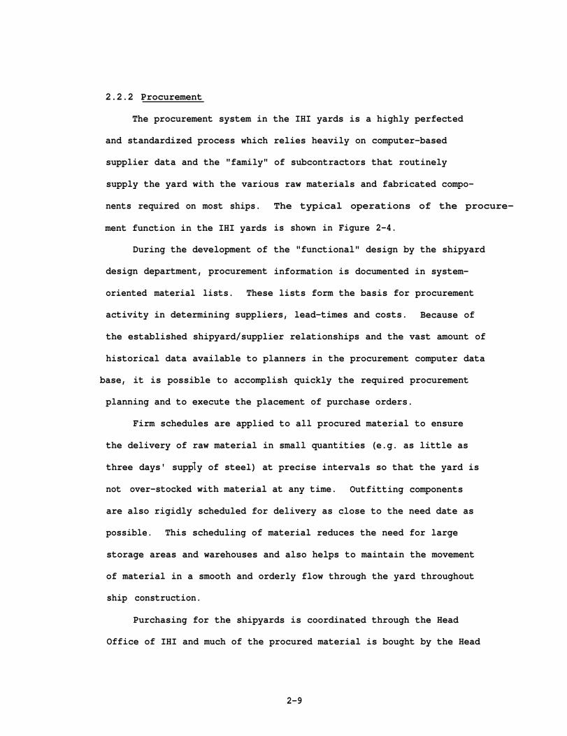
2.2.2 Procurement
The procurement system in the IHI yards is a highly perfected
and standardized process which relies heavily on computer-based
supplier data and the "family" of subcontractors that routinely
supply the yard with the various raw materials and fabricated compo-
nents required on most ships.
ment function in the IHI yards
During the development of
design department, procurement
The typical operations of the procure-
is shown in Figure 2-4.
the "functional" design by the shipyard
information is documented in system-
oriented material lists. These lists form the basis for procurement
activity in determining suppliers, lead-times and costs. Because of
the established shipyard/supplier relationships and the vast amount of
historical data available to planners in the procurement computer data
base, it is possible to accomplish quickly the required procurement
planning and to execute the placement of purchase orders.
Firm schedules are applied to all procured material to ensure
the delivery of raw material in small quantities (e.g. as little as
three days' supp
not over-stocked
are also rigidly
y of steel) at precise intervals so that the yard is
with material at any time. Outfitting components
scheduled for delivery as close to the need date as
possible. This scheduling of material reduces the need for large
storage areas and warehouses and also helps to maintain the movement
of material in a smooth and orderly flow through the yard throughout
ship construction.
Purchasing for the shipyards is coordinated through the Head
Office of IHI and much of the procured material is bought by the Head
2-9

Office Procurement Group. This allows economic lot-quantity buying
wherever possible.
2.2.3 Manufacturing
As in most shipyards the major production activities are divided
into hull construction and outfitting. Each of these activities are
organized and executed by a separate "Workshop". Hull construction
encompasses all steel fabrication, sub-assembly, assembly and erection
of the final hull units. Outfitting is planned and organized to
correspond with the hull construction work so that appropriate out-
fitting of components and sub-assemblies is accomplished at the best
time during manufacture of the steel unit assemblies.
The manufacture of steel parts and pieces, the assembly of these
components into progressively larger and more complex units, and
ultimately the construction of these units into the ship itself, is
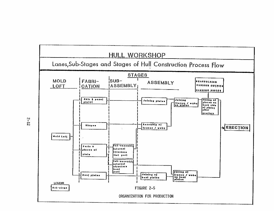
the function of the Hull Construction Workshop. In IHI the process of
hull construction is a well defined system which utilizes designated
material flow routes called "process lanes" for the processing of all
material. "process Lanes" extend through several different physical
areas either within shops or assembly areas in a series of operations
referred to as "Sub-stages". These "Sub-stages" are part of a larger
process step called a "stage". Figure 2-5 illustrates this organiza-
tion of production into the various process lanes, sub-stages and
stages.
This type of production system aligns the physical
overall facility into several material flow paths which
areas of the
begin with
the fabrication of detail parts and pieces, the subsequent sub-assembly
2-11


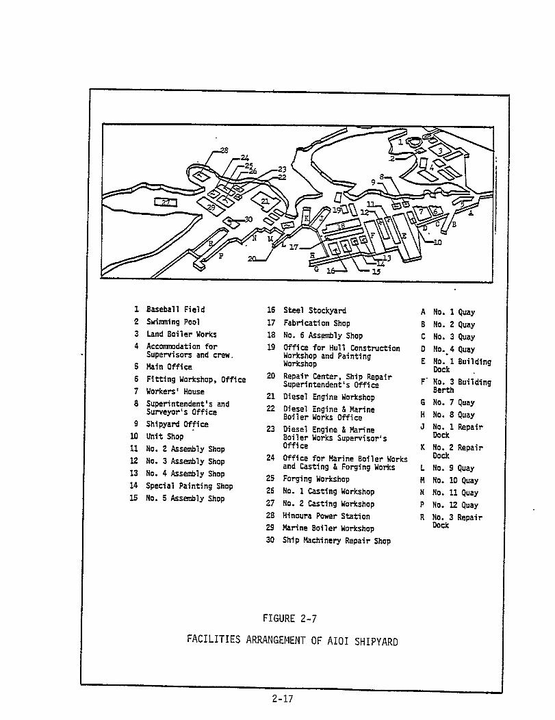
The Aioi Shipyard is a compact area occupying the middle portion
of the complex and consisting of a steel stockyard, a fabrication shop,
several assembly and outfitting shops and areas, a pipe shop, a unit
painting shop and two large building basins. Additionally, several
shops, quays and dry docks are dedicated to ship overhaul and repair.
The Aioi yard comprises a total of 6,832,965 square feet of space
of which 1,715,750 sq. ft. are utilized for shops, assembly areas
and other working areas. Some 49 percent of the total utilized area
(i. e. that stated above) is covered by permanent or temporary (i.e.
moveable) enclosures.
The two building basins used for new construction have a capacity
for up to 180,000 DWT vessels in the larger basin and up to 164,000 DWT
vessels in the smaller basin. The larger basin is serviced by two
200-ton cranes and two 70-ton cranes. The smaller basin is serviced
by two 120-ton cranes and two 80-ton cranes.
The flow of material within the yard is shown in Figure 2-8. As
shown in the figure, steel moves from the stesl stockyard through shot
blasting and painting to either N/C cutting machines or the Electro-
Photo Marking machine and then to the N/C cutting machines. These
operations occur in one of the fabrication and sub-assembly bays of
the main fabrication shop. Material processed in the fabrication
shop is routed to one of several "Process Lanes" according to its
eventual use in flat-panel or curved units. Sub-assembly of the
fabricated parts and pieces occurs at the exit end of the four fabri-
cation bays. Sub-assemblies are then routed to one of several
assembly yards to be joined with other sub-assemblies or incorporated
2-18

into the unit being built-up in that yard. Pre-outfitting of the unit
occurs at appropriate points in the build-up with the installation of
pre-assembled outfitting component sub-assemblies or of individual
outfitting components. When the unit is complete, it is moved either
to the platen area of the building basin or to a unit storage area.
Deck house units are built in an area separate from the other units.
This "superstructure" assembly area is self-contained to provide all
necessary finishing and outfitting of the house unit. The pipe shop,
which is not shown on the figure, is located further to the North of
the Outfitting Shop. Pipe components and sub-assemblies are moved
to the appropriate outfitting location when required by the outfitting
schedule.
2.4 PERSONNEL
The IHI shipyards are often part of a "District" or larger complex
which produces several products other than new ships, such as diesel
engines (as explained in paragraph 2.3). However, the shipyard
portion of the complex is organized as a separate entity within this
District, reporting to a General Superintendent. The organization
within each of the shipyards is generally the same throughout the IHI
yards. Figure 2-9 shows the typical organization for these yards.
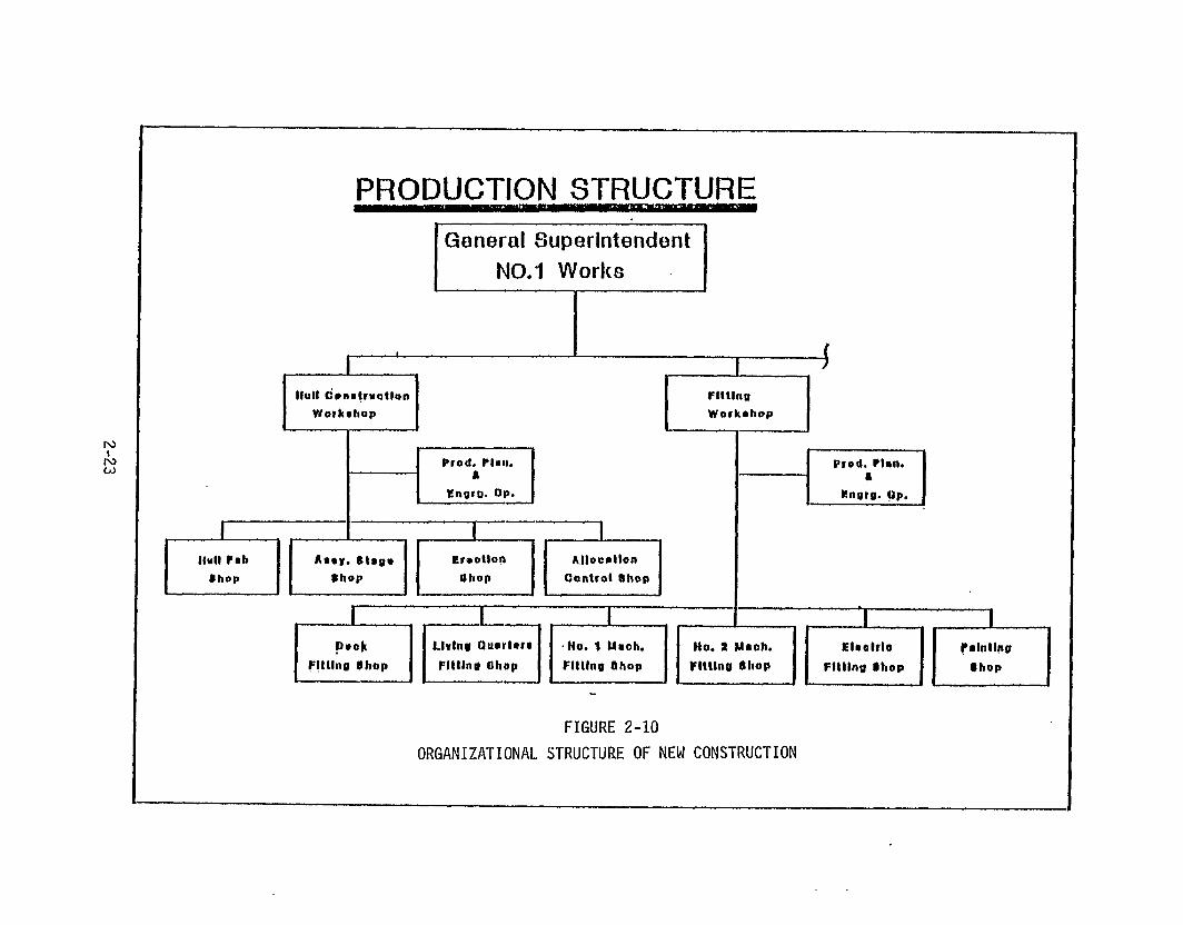
The shipyard General Superintendent maintains five primary (or
line) functions for the accomplishment of new ship construction and
ship repair.
Construction
and the Ship
for both new
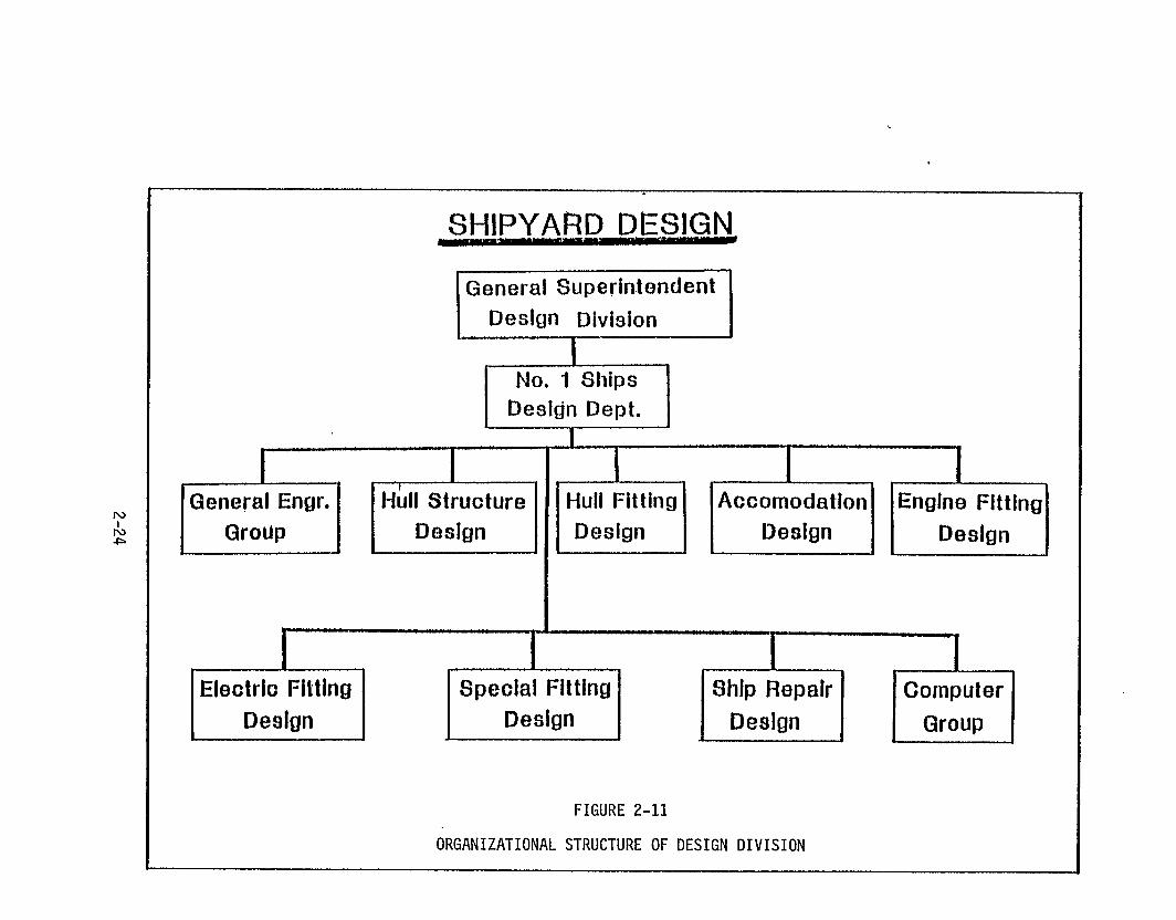
These are the Design Division (or Department), the Hull
Workshop, the Outfitting Workshop, the Panel Workshop
Repair Workshop. The Panel Workshop provides panels
construction and for ship repair and is, therefore,
2-20


SECTION 3
THE IHI PLANNING SYSTEM
3.1 GENERAL
The IHI Planning system consists basically of two major activities -
the planning for hull construction and outfit planning - extending
through three stages of development: Preliminary Planning, Detailed
Planning and Working Instruction Planning. Of these two activities,
hull construction planning is the primary activity while outfit
ning is accomplished essentially on the basis of the production
of the hull units. Therefore, in this discussion the two types
plan-
of
planning will be discussed separately beginning with hull construction.
It is difficult to discuss planning, as it is accomplished in
the IHI shipyards, as separate from scheduling since much of the plan-
ning is concerned with the development of schedules which coincide
with the processes and movement of material through the production
activities. The absence of this scheduling activity in any such
discussion would seriously degrade the proper
planning activities and the flow of events in
Therefore, scheduling activities are included
understanding of the
the planning cycle.
in this discussion
where applicable, although a more definitive and comprehensive study
of the scheduling hierarchy, methods and techniques is provided in
Section 4.
This section of this report expressly deals with the planning
system utilized by IHI. In preparing this report it became apparent
3-1
that the various yards of IHI use somewhat different terminology for
the various elements developed during the planning phase. Also, in
a later section the Livingston adaptation of this IHI planning system
is described. This Livingston system uses still other terminology
from that presented in this section. Every effort has been made to
avoid confusion from this disparity in terminology, however, to help
in clarifying the various terms and the description of the two systems
a glossary of terms is provided as Appendix A to this report. Also,
to assist the reader in assimilation of the information concerning the
many planning documents utilized in the IHI planning system, Table
T3-1 provides a listing of the plans and their application in the
ship construction process.
3.2 HULL CONSTRUCTION PLANNING
Hull construction planning follows a prescribed methodology which
progressively breaks down and details successively lower levels of the
hull until the parts and pieces at the lowest level of fabrication
are completely defined. This methodology is based on a “Product-
Oriented Work Breakdown Structure" (see Appendix B) although the
actual activity of defining the ship into its detail parts follows
a somewhat different and more pragmatic approach. Essentially, the
steps followed by shipyard engineers performing this breakdown are:
1 . Unit division (i.e. dividing the ship into major unitscapable of being assembled, transported and erected);
2. Assembly breakdown (i.e. defining the component sub-assembliesand detail parts which constitute each of the units);
3. Specifying the fabrication, sub-assembly and assembly methodsto be used in the fabrication of the detail parts and thebuild-up of these parts into progressively larger and morecomplex assemblies.
3-2

This methodology is well known to U.S. industries. It is the
system developed long ago for engineering drawing development and for
assembly line production. This system was developed and established
as the traditional production methodology for the U.S. aircraft
industry during World War II. Its application to shipbuilding is also
well known and understood although few shipyards employ
degree that the IHI yards do.
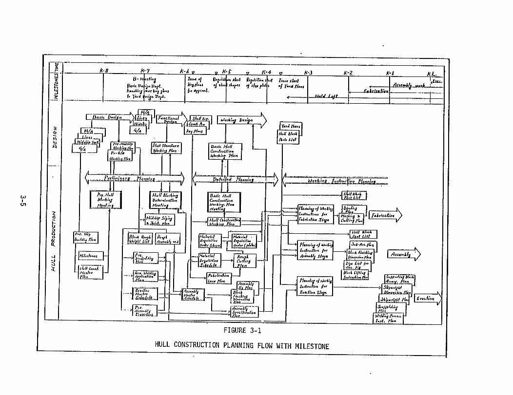
While this breakdown of the overall product and of
lower-level "interim" products is being accomplished, a
it to the
the successive
host of other
planning activities are taking place.
confirmed; fabrication, sub-assembly,
are determined; material requisitions
Facilities arrangements are
assembly and erection processes
are determined and issued; and
manpower and performance measurement requirements are established.
Figure 3-1 depicts the flow of planning activities prior to the start
of hull construction.
To describe the individual planning efforts taking place during
the planning phase of a new ship construction program, planning activi-
ties are described as they occur in each of the three time periods
specified above, i.e., Preliminary Planning, Detailed Planning, and
Working Instruction Planning.
3.2.1 Preliminary Planning
Hul1
the Basic
Office in
construction planning begins immediately upon completion of
Design (accomplished by the Design Department in the Head
IHI in Tokyo). The Basic Design consists of: Unfaired
Ship’s Lines, Midship Section,
ment and Machinery Arrangement
Construction Profile, General Arrange-
drawings. On the basis of these plans,
3-4

the shipyard Design Department undertakes the breakdown of the ship
into "Blocks" or units. This activity is called "Hull Block Planning”
and consists of dividing the ship into manageable units suitable for
assembly and erection.
This planning generally centers initially around the midship
sections (i.e. cargo holds) since these sections represent the majority
of ship units and because of the repetitive nature of the midship
section units. The bottom units of these cargo hold sections are also
the starting point for the development of the requirements for curved
(bottom) units. Forward and aft sections of the ship are necessarily
treated individually and require a more in-depth analysis to determine
proper division into units.
Beginning with the bottom midship section of the ship, units are
defined using the following criteria:
1) First unit to be laid in the
the midship section unit just forward
2) Crane Capacity - The size of
building basin (this is generally
of the engine room).
the units must be restricted
to the lifting capacity of the available cranes both in the assembly
areas and in the erection area.
3) Assembly Areas - Unit size is further limited by the size
of the assembly areas and facilities such as over-turning equipment,
transporters, cranes, etc. During over-turning and transportation
the unit size must not be so great that deformation will occur during
lifting or movement.
4) Work Flow - Unit size should be kept at an optimum to provide
maximum work flow through the production work stations. Too big a
3-6

unit would require a prolonged assembly time thus creating a “bottle-
neck" for following work.
5) Reduction of Erection Work - Unit size and shape must be
capable of being eas"
Welding lengths must
welding requirements
ly erected and must be stable during joining.
be minimal, especially for difficult (overhead)
6) Unit Outfitting - Assembly and outfitting schedules must be
taken into consideration in sizing units. Units of too large a size
or requiring an inordinate amount of outfitting will cause schedule
delays, consume assembly area space, and delay following work (which
may also result in idle time in following work stations).
Using the above criteria, the ship is divided into manageable
units which fit the facilites, equipment, manpower, and schedules
established for ship construction. The overriding concern during
this planning step is to derive the highest productivity at the
stages of assembly and erection, and to maintain the highest accuracy
of the manufactured units. Figure 3-2 presents an example of a ship’s
hull divided into units by the above process. Appendix C provides
additional information concerning this process.
3.2.1.1 Unit Assembly Planning
After division of the ship into manageable units, typical common-
shaped units are analytically disassembled in a progressive breakdown
from the entire unit to the component sub-assemblies and then to the
parts and pieces which constitute the sub-assemblies. All unique
units are broken down in this manner. Figure 3-3 shows a typical
example of such a breakdown.
3-7


These breakdowns serve
the basic assembly sequence
several purposes in addition to showing
of each unit. A preliminary evaluation
of the assembly sequence yields details concerned with the necessary
facilities and processes required for the assembly, e.g., required
fitting jigs, probable welding processes, required assembly area size
and capacity. Further details are developed including: the classifi-
cation of sub-assemblies and assemblies; reference level and line;
length and types of.welding joints; welding edge-preparation require-
ments; and requirements for added material for adjusting seam and
butt lines. Appendix D provides examples of this planning.
All of this planning is considered "preliminary" information for
the development of "detailed process planning" which is documented
and disseminated as "Assembly Specification Plans" and "Working
Instruction plans".
3.2.1.2 Schedules & Plans
A Master Key Event Schedule showing milestones such as Program
Start, Fab Start, Keel Laying, Launch and Delivery is determined
when the ship is placed under contract. This schedule is estab-
lished by the Head Office with input from the shipyard which will
accomplish the ship construction. On the basis of this schedule,
preliminary milestone schedules and general hull construction plans
are generated. This rough information is considered in the formulation
of the hull block planning.
A rough Unit Weight List, a unit assembly plan, a scaffolding
plan, an auto-welding application plan, a midship sizing and joining
plan and an erection master schedule are established for consideration
3-1o

at a general meeting held to
initial Hull Blocking Plan.
planning is begun.
review and determine
Upon approval of the
the validity of the
plan, detailed
3.2.2 Detailed Planning
During the preliminary planning stage, the Basic Design generated
by the Head Office Design Department is refined and elaborated to the
extent necessary to fix the Hull Blocking Plan. This design is refer-
red to as the Functional Design and upon approval of the Hull Blocking
Plan the Working Design is started.
At the start of the detailed planning stage, the Assembly Master
Schedule is prepared from the Erection Master Schedule. On the basis
of this schedule, the Material Requisition Schedule and Material
Requisition Orders are prepared. Detailed Hull Construction Working
Plans (drawings) are also prepared by the Design Department defining
the assembly units identified in the Hull Blocking Plan. A meeting,
such as was held for the review of the Hull Blocking Plan, is held
for a similar review and approval of the Hull Construction Working
Plans.
Based on these working plans and on the material requisition
schedule and a Fabrication Lane Plan (which details the processing
of plate steel through the fabrication shops), a Rough Cutting Plan
is generated. This plan is
Material Requisition Orders
of sizes, thickness and the
made to assist in the preparation of
for steel plates to minimize the number
total quantity of plates required. The
purpose of the plan is to improve the usage and control
and scraps; to determine the quantity of steel required
of remnants
each month;
3-11
and to provide guidance for
the workshop. The Material
basis of the information in
the preparation of the
Requisition Orders are
this plan.
3.2.2.1 Assembly Specification Plans
Based on the information developed during the
planning", formal Assembly Specification Plans are
Cutting Plan to
prepared on the
"preliminary process
developed. These
plans detail the methods to be followed during fabrication, assembly
and erection. This planning is accomplished by engineering personnel
in the Design Department and by accuracy control engineers in the
various workshops.
Assembly Specification Plans are prepared for units of the fore
and aft sections of the ship and for typical midship (cargo holds)
sections. Evaluation of the assembly sequence is made to determine
the assembly process lanes which must be used for curved versus flat
units. This evaluation concerns an in-depth analysis of the processes
through which each of the piece parts and the sub-assemblies must flow
in order to be collected and assembled in the least possible time while
simultaneously achieving full utilization of manpower, facilities and
equipment. Figure 3-4 is an example of the Assembly Specification
Plan prepared at this stage.
The planning accomplished during the preparation of the Assembly
Specification Plans provides progressively more detailed information
for lower-level planning in the workshops. From this relatively
broad planning for assembly of units, Detailed Assembly Specification
Plans are developed
assembly procedures
for each unit.
to be utilized
These plans provide more precise
by the workshop personnel.
3-12

The
utilized
of jigs;
accuracy
process;
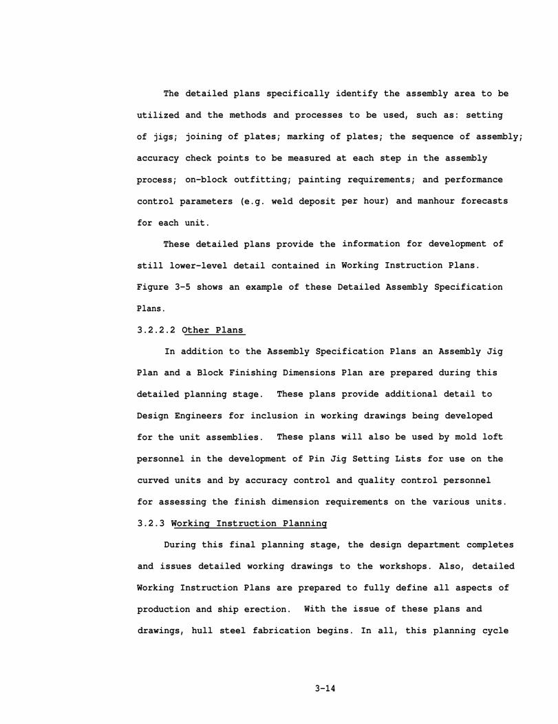
detailed plans specifically identify the assembly area to be
and the methods and processes to be used, such as: setting
joining of plates; marking of plates; the sequence of assembly;
check points to be measured at each step in the assembly
on-block outfitting; painting requirements; and performance
control parameters (e.g. weld deposit
for each unit.
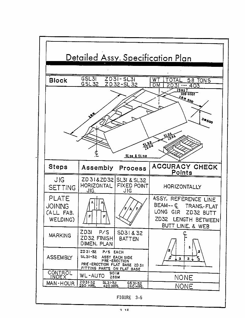
These detailed plans provide the
still lower-level detail contained in
per hour) and manhour forecasts
information for development of
Working Instruction Plans.
Figure 3-5 shows an example of these Detailed Assembly Specification
Plans.
3.2.2.2 Other Plans
In addition to the Assembly Specification Plans an Assembly Jig
Plan and a Block Finishing Dimensions Plan are prepared during this
detailed planning stage. These plans provide additional detail to
Design Engineers for inclusion in working drawings being developed
for the unit assemblies. These plans will also be used by mold loft
personnel in the development of Pin Jig Setting Lists for use on the
curved units and by accuracy control and quality control personnel
for assessing the finish dimension requirements on the various units.
3.2.3 Working Instruction Planning
During this final planning stage, the design department completes
and issues detailed working drawings to the workshops. Also, detailed
Working Instruction Plans are prepared to fully define all aspects of
production and ship erection. With the issue of these plans and
drawings, hull steel fabrication begins. In all, this planning cycle
3-14

consumes from six to eight months of the total ship construction
schedule. This thorough planning however, serves to considerably
reduce both the time required for ship construction and also the cost
of production.
Working Instruction Plans represent the final planning step, and
are derived from the functional and detailed design, Detailed Assembly
Specification Plans, and the other data which have been progressively
developed from the Basic Design for each unit. Morking Instruction
Plans provide detail working-level data for the fabrication, assembly
and erection of each unit. These plans complete the development of
data from the design level information to the working level details
necessary for workshop execution.
Three Working Instruction Plans are prepared for each unit in
the area of fabrication: Marking Plan, Cutting Plan and Bending Plan
(often the Marking and Cutting Plans wi11 be combined into a single
plan).
In the area of assembly, six plans are prepared on each unit as
follows:
Part Lists
Finishing Dimensions Plan
Sub-assembly Plans
Assembly Plans
Lifting Instructions Plan
Working Instruction Plans originated for erection include:
Arrangements Plan
Shipwright Dimensions Plan
3-16
Support Block Arrangements Plan
Welding Instruction Plan
Scaffolding Arrangements Plan
These plans provide all necessary information at
stage for the proper manufacture and handling of each
basic objectives intended for these plans are: 1) to
each production
unit. T h e
effect control
of the total workload and the products as the work progresses through
the various process lanes, sub-stages and stages of the production
system; 2) to effect control of the great number of parts and pieces
of material as they flow through the production processes; and 3) to
provide explicit instructions to all levels of personnel concerned
with the fabrication, assembly and erection of ship components.
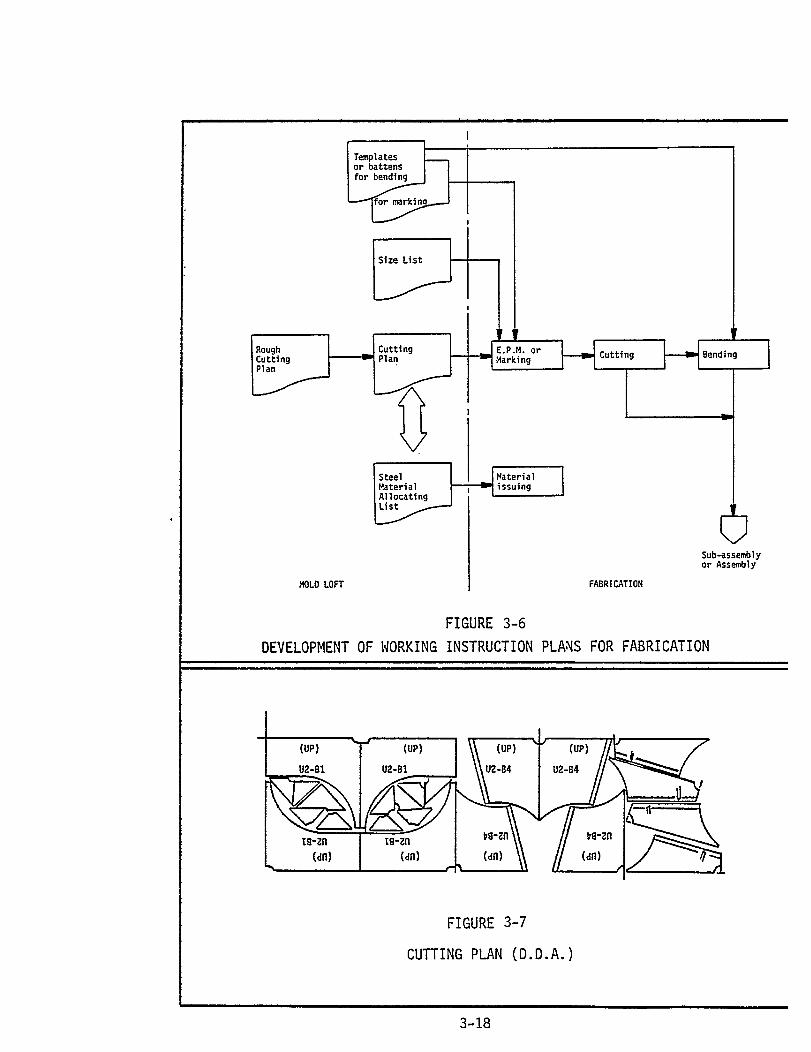
3.2.3.1 Working Instruction Plans for Fabrication
Three plans are prepared for the fabrication processes: a Marking
Plan; a Cutting Plan and a Bending
chart representing the development
3.2.3.1.1 Cutting Plans
Plan. Figure 3-6 presents a flow
of these plans.
These plans are constructed from Rough Cutting Plans by inserting
small computer-prepared drawing pieces on a sheet of layout paper for
each process lane and for each unit. This composite is used by workers
to
of
mark parts and pieces on steel plates. Figure 3-7 shows an example
this method.
These plans can also be constructed by affixing 1/10 scale
drawings (transparent film) of the parts and pieces, (drawn in the
automated drafter) on to a transparent base film.
Marking on the plate is accomplished by projecting the transparency
3-17

on to the plate in full scale which exposes a photo-sensitive powder
on the plate causing the powder to adhere to the projected lines on
the plate’s surface. This is called Electro Photo Marking (EPM).
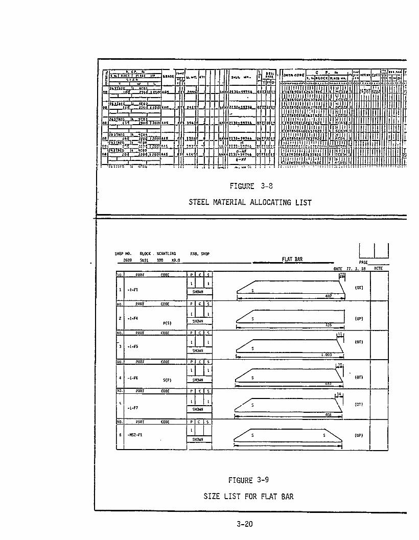
Steel Material Allocating Lists
These lists are prepared from Material Requisition Orders which
are developed from the completed Cutting Plans. These lists are
issued, together with the Cutting Plans, as Steel Material Issue Orders
for the shops for the marking and cutting of material. Figure 3-8
provides an example of these lists.
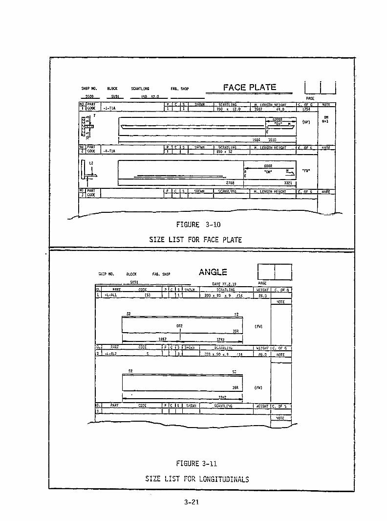
Size Lists
Size lists also accompany the Cutting Plans. These lists specify
the size of flat bars, face plates, longitudinal for each material/
unit/process lane. These lists provide information for the cutting
of these items on plate remnants or on one entire plate regardless of
the number of units involved. Figures 3-9 through 3-11 show examples
of these lists.
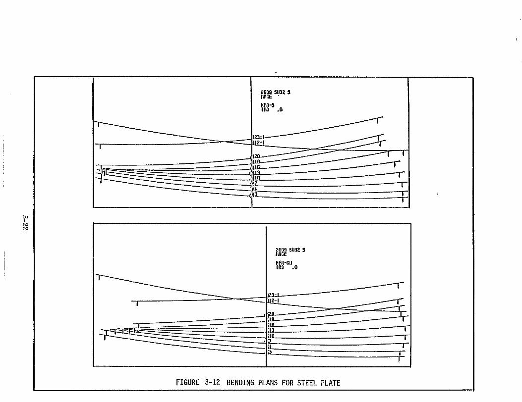
3.2.3.1.2 Bending Plans
Bending plans are prepared for both steel plate and shapes.
1/10 scale plans are prepared by the computerized drafting system,
(SHELL - Shell Expansion and Logical Layout System) for plate bending.
Bending jigs are then used for the actual bending.
Figure 3-12 shows a 1/10 scale plan produced by the Automatic
Drafter. Full size plans are used by Mold Loft personnel by projecting
the scale drawing to full size and indicating the sizes necessary
for making templates on the full sized plans. Figure 3-13 illustrates
a Size List for Bending Plans for steel plates.
3 - 19
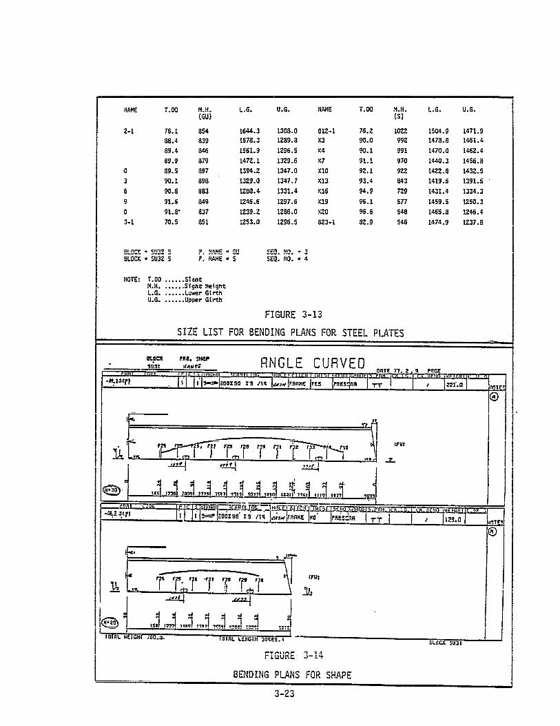

Bending Plans for Shapes show a curved line marked on webs as a
guideline for bending. The bending of the shape is performed by
straightening the curved line which has been marked on the material.
Figure 3-14 illustrates this mehtod.
3.2.3.2 Working Instruction Plans for Sub-assembly and Assembly
The Norking Instruction Plans for sub-assembly and assembly are:
Parts Lists
Lifting Instruction Plans
Sub-assembly Plans
Assembly Plans
Finishing Dimensions Plans
Size Lists for Assembly Jig
Each of these plans are described below.
3.2.3.2.1 Parts Lists
These lists are issued for each unit for each production stage
(i. e., Sub-assembly, Assembly and Erection). These lists are used by
workers at each stage to assure the collection of components and that
all components have been properly installed. Figures 3-15 and 3-16
show examples of the Parts List.
3.2.3.2.2 Lifting Instructions Plan
A Lifting Instructions Plan is prepared for each unit. This
plan provides information for the attachment of pad eyes, the attach-
ment of any reinforcing material required during lifts, attachment
of pieces on the unit
erection, the loading
weight and the safety
that will be required for joining during
weight for lifting devices, the total block
margin for all lifting conditions.
3-24


This plan is carefully constructed taking into consideration
all movement of the unit during transport, over-turning and final
erection of the unit on the ways. Figure 3-17 depicts the development
of the plan for each unit. Figure 3-18 shows an example of the plan
for one type of unit.
3.2.3.2.3 Working Instructions Plan for Sub-assembly
Sub-assembly plans for each unit are prepared to show the details
of constructing the one or more sub-assemblies which will be included
in the final units. These plans show necessary alignment, welding
and
for
the
finishing requirements together with the outfitting requirements
each sub-assembly. Figure 3-19 shows the development flow for
preparation of these plans. Figures 3-20 and 3-21 present examples
. of the type of instructions conveyed by these plans.
3.2.3.2.4 Working Instructions Plan for Assembly
Details of unit assembly are presented in these plans. Figure
3-22 shows the development flow of these plans. These
information from Assembly Specification Plans and yard
and simplify the data through presentation in the form
3-23 and 3-24.
3.2.3.2.5 Finishing Dimensions Plan
plans extract
working drawings
shown in Figures
This plan is prepared for each unit to show applicable reference
lines for assembly and erection, diagonal dimensions, fitting lines
for outfitting parts and pieces and several other critical dimensions
related to outfitting and installation of the unit during erection.
Figure 3-25 illustrates the development of these plans and the
pertinent information presented for each unit. Figure 3-26 shows an
example of one such plan.
3-26


3.2.3.2.6 Assembly Jig Arrangement Plan
These plans, prepared for each curved unit, designate necessary
information on the approximate size of plates, the gap length between
the welding seam and the fixed point jigs, the position of the first
setting plate, the weight of the jigs, and the slant of the frames.
These plans are required for the adjusting or building of a proper
curved unit assembly jig and for assembly area planning. Figure 3-27
shows the process of developing these plans and Figure 3-28 presents
an example of an Assembly Jig Size List which provides the information
for the construction of the jig for one unit.
3.2.3.3 Working Instruction Plans for Erection
Working Instruction Plans for the Erection Stage are:
3.2.3.3.1
These
individual
Hull Blocking Plans
Shipwright Dimensions Plans
Supporting Block Arrangement Plans
Welding Process Instruction Plans
Scaffolding Arrangement Plans
Hull Blocking Plans
plans provide detailed information for the erection of the
hull units. In addition to the drawing showing the division
of the ship into hull units other data includes information on:
Hull joints
Positions of joints in the distance from someframe
Unit Code and Number
Erection sequence and direction
Insert blocks
3-35


- Loose plate and temporarily affixed pieces
- Sections in charge of work
- Access holes for working
- Bevel angle for welding at Erection Stage
- Frame spaces
- Longitudinal spaces
- Overlapping length of frames on skin plates
- Welding leg Length
- Scantling
Figure 3-29 provides an example of a hull blocking drawing.
3.2.3.3.2 Shipwright Dimensions Plans
These plans, which are prepared by computer (through a sub-system
of the IHI Computer System or IHICS) describe the position of each
unit in the erection sequence. This position is described by reference
to adjacent frames. Figure 3-30 provides an example of this plan.
3.2.3.3.3 Supporting Block Arrangement Plans
These plans
support blocks.
Figure 3-31
show the arrangement of under-keel and under-frame
Considerations for making these plans are:
Loading weight for each block . . . ..3O - 40 tons/unit
(Special attention is given to the blocks underEngine Room.)
Arrangement suitable for shipwrighting
Prevention of shell plate damage at launch
presents an example of this type of plan.
3.2.3.3.4 Welding Process Instruction Plans
Welding instructions are determined by the Hull Construction
Workshop for inclusion in yard working drawings. These plans provide
3-37


information concerning automatic and semi-automatic welding processes
for each hull unit. Bevel information is also included. These plans
also provide detail instruction to welders during the erection process.
Figures 3-32 and 3-33 provide examples of these instructions.
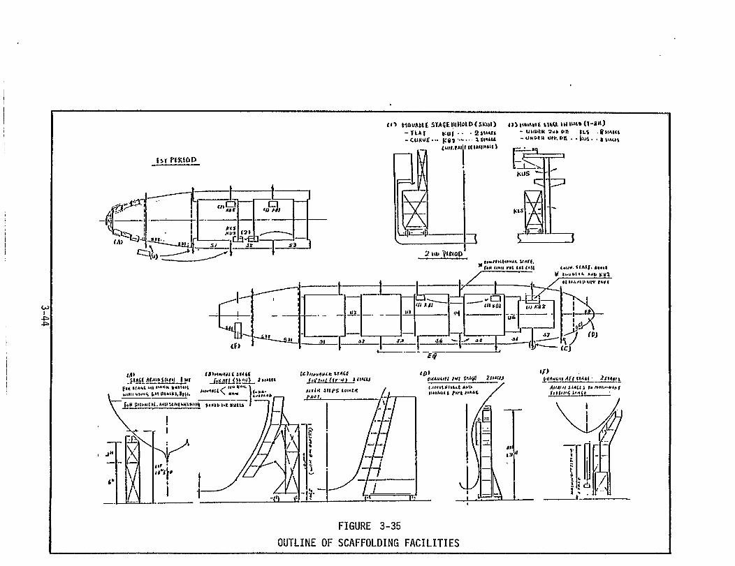
3.2.3.3.5 Scaffolding Arrangement Plan
The scaffolding plan prescribes the use of both interior and
exterior scaffolding during ship erection. The use of moveable
scaffolding stages greatly facilitates the use of the scaffolding
but necessitates a definitive plan for its erection and take-down.
Information regarding scaffolding hangers and materials described in
this plan is also included in sub-assembly and assembly plans.
Figures 3-34 and 3-35 present examples of the information contained
in these plans.
3.3 OUTFIT PLANNING
In IHI outfit planning begins immediately upon receipt of the
Basic Design and parallels hull construction planning in the develop-
ment of the Hull Blocking Plan, Unit Assembly Plans and the develop-
ment of the functional and detailed design.
The IHI shipyards accomplish as much "pre-outfitting" of hull
units as possible during the construction of these ship elements.
This, of course, greatly reduces the amount of outfitting work that
must be done during erection and after launch. The manhour and cost
savings attributable to this approach are considerable and this
approach is another
yards.
Pre-outfitting
factor in the high productivity achieved by these
is a logical and highly effective method for
reducing ship construction costs especially in light of the "modular"
3-41


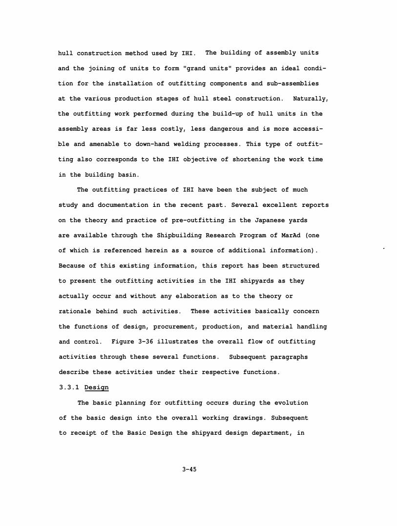
hull construction method used by IHI. The building of assembly units
and the joining of units to form "grand units" provides an ideal condi-
tion for the installation of outfitting components and sub-assemblies
at the various production stages of hull steel construction. Naturally,
the outfitting work performed during the build-up of hull units in the
assembly areas is far less costly, less dangerous and is more accessi-
ble and amenable to down-hand welding processes. This type of outfit-
ting also corresponds to the IHI objective of shortening the work time
in the building basin.
The outfitting practices of IHI have been the subject of much
study and documentation in the recent past. Several excellent reports
on the theory and practice of pre-outfitting in the Japanese yards
are available through the Shipbuilding Research Program of MarAd (one
of which is referenced herein as a source of additional information).
Because of this existing information, this report has been structured
to present the outfitting activities in the IHI shipyards as they
actually occur and without any elaboration as to the theory or
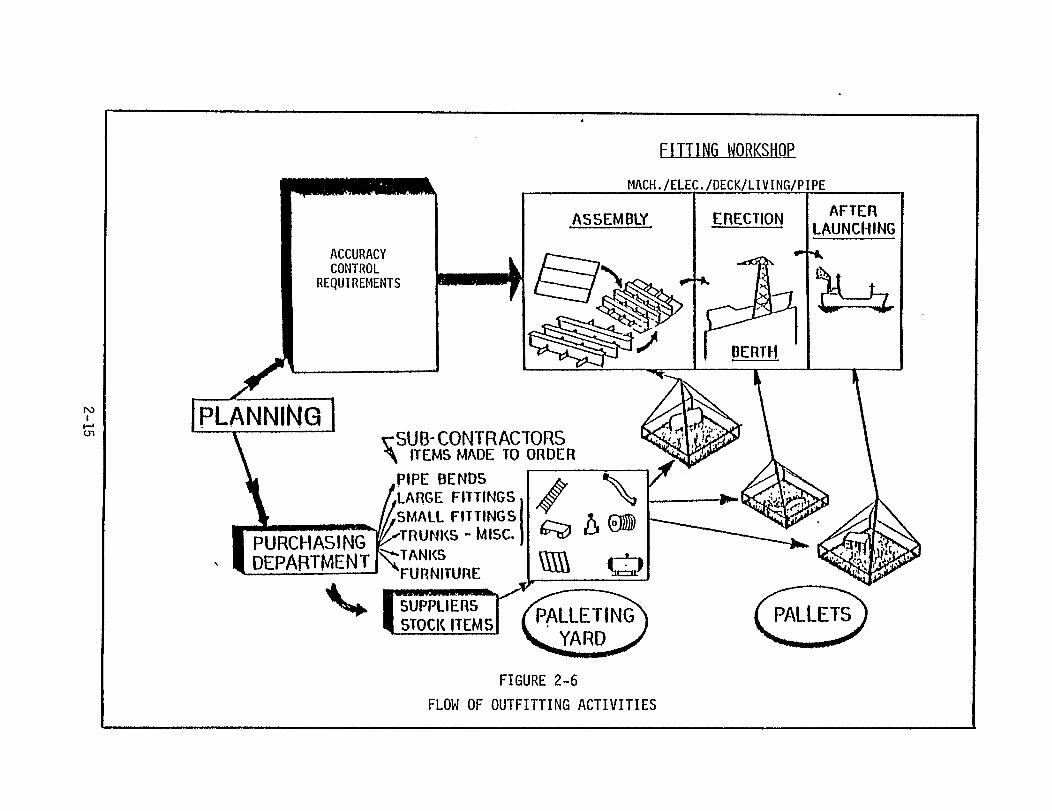
rationale behind such activities. These activities basically concern
the functions of design, procurement, production, and material handling
and control. Figure 3-36 illustrates the overall flow of outfitting
activities through these several functions. Subsequent paragraphs
describe these activities under their respective functions.
3.3.1 Design
The basic planning for outfitting occurs during the evolution
of the basic design into the overall working drawings. Subsequent
to receipt of the Basic Design the shipyard design department, in
3-45


collaboration with the Fitting Workshop Production Planning and Engineer-
ing staff, develops system diagrams for each functional system of the
ship. The diagrams define all components required in each functional
system but do not reflect any sub-division of the ship into units or
zones. On the basis of these diagrams, a Material List by System (MLS)
is compiled. These lists provide an itemization of the bulk and raw
materials and system components required for a particular Material
Ordering Zone. Figure 3-37 provides an example of an MLS.
IHI establishes a series of "Zones" for each ship: major zones,
which are primarily used for sub-dividing the ship for the purpose of
hull construction; Material Ordering Zones, which are used to categorize
material for procurement; Outfitting Zones, which designate major areas
of outfitting; and Outfitting Work Zones, which are further sub-divisions
of Outfitting Zones into discrete small packages of outfitting work.
Figure 3-38 illustrates these different types of zones.
Material Ordering Zones range from four to seven depending on the
type of ship. The first four zones are: the cargo hold, the engine
room, the main deck, and the house. Electrical outfitting is nearly
always considered as a separate zone which makes five basic zones of
a ship such as a tanker or bulk carrier. Container ships or combina-
tion
Zone
container/bulk carriers would require additional material zones.
The system-oriented material lists (MLS) for each Material Ordering
are sent to the Material Procurement Department for scheduling
and ordering. Because of the wealth of historical data accumulated by
the IHI yards over the past decades and because of the unique relation-
ships between these yards and subcontractor/suppliers (which generally
3-47


reside in proximity to the yards), the yard procurement function is able
to construct immediately valid lead-time and cost information.
The majority of such information resides in a procurement computer
data bank and is constantly updated by procurement personnel. A more
complete explanation of the procurement function is presented in sub-
sequent paragraphs.
The system diagrams developed by the Engineering Department are
part of the second stage of design development which is called
"Functional Design". This stage translates the Basic Design to the
next logical level of development, i.e. Detail Design.
During the Detail Design stage, the data from the functional design
is converted into working drawings of unit assemblies, sub-assemblies,
detail parts and pieces, etc. Also, at the detail design stage an
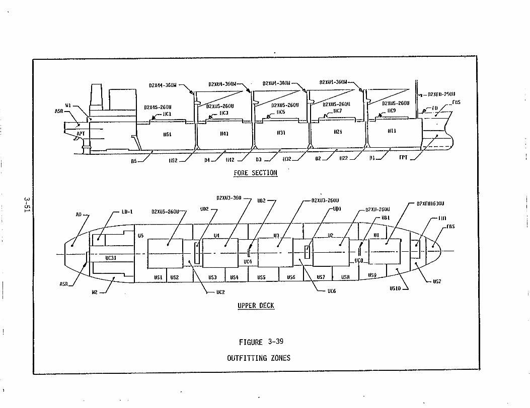
Outfitting Zone Plan is developed for the ship. This outfitting zone
planning essentially sub-divides the major ship zones into smaller
areas concerned with outfitting activities in the major ship sections,
i.e., cargo hold, engine room, deck house, main deck, etc. An "Out-
fitting Zone" is simply a geographical area (3-dimensional) of the
ship having no relation to a particular system. Instead all systems
within a given area are encompassed by the zone boundaries. An Out-
fitting Zone can represent a portion of a deck, a portion of several
decks, one or more compartments, parts of adjacent compartments, etc.
Figure 3-39 illustrates the Outfitting Zones identified for one type
of ship.
The criteria for sub-dividing the ship into outfitting zones are
based on the hull breakdown (in the Hull Blocking Plan), and the
3-50
identification of logical packages of outfitting work at each of the
production stages of sub-assembly, assembly and erection. This identi-
fication of work packages parallels the construction of the steel sub-
assemblies and assemblies since outfitting must be accomplished at
precise periods in the hull construction schedule. As a consequence,
Outfitting Zones are identified which correspond to the hull units
specified in the Hull Blocking Plan.
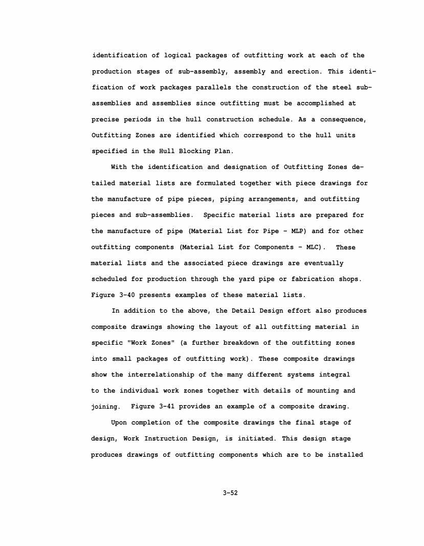
With the identification and designation of Outfitting Zones de-
tailed material lists are formulated together with piece drawings for
the manufacture of pipe pieces, piping arrangements, and outfitting
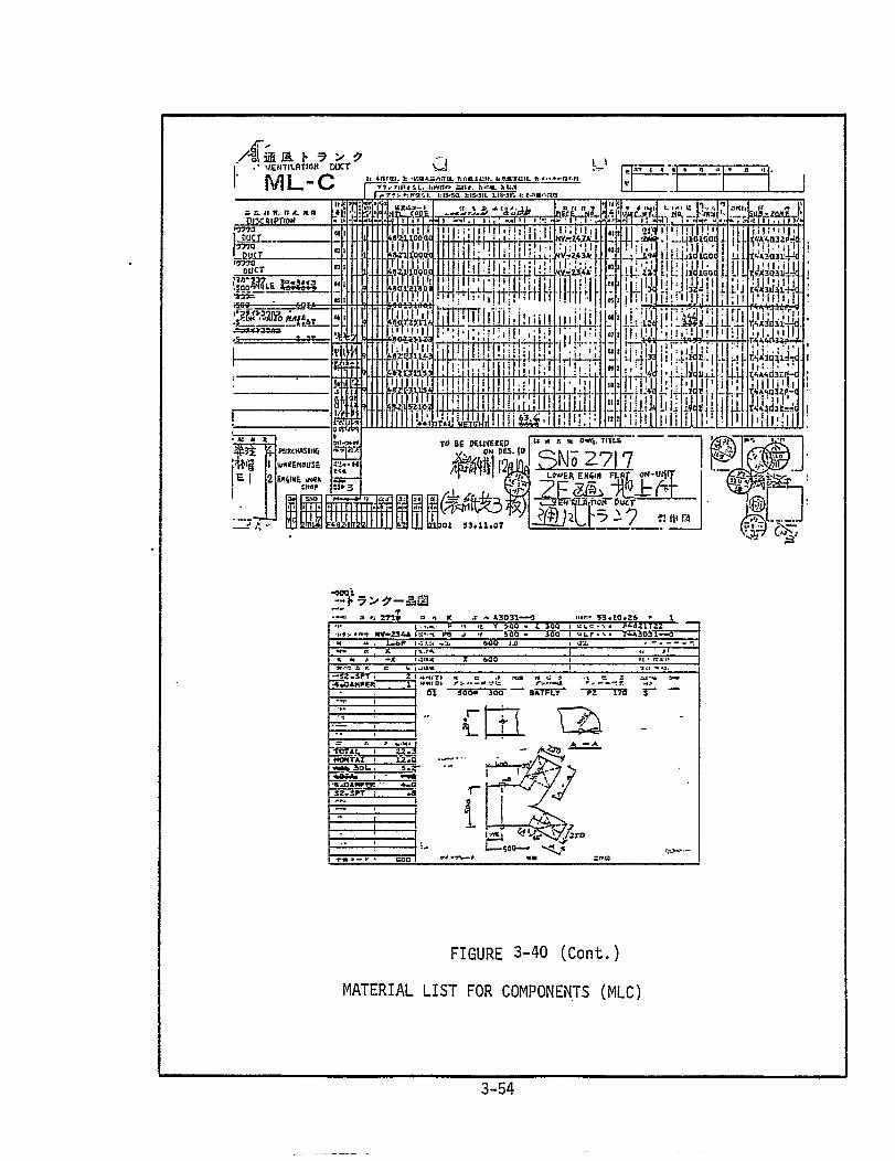
pieces and sub-assemblies. Specific material lists are prepared for
the manufacture of pipe (Material List for Pipe - MLP) and for other
outfitting components (Material List for Components - MLC). These
material lists and the associated piece drawings are eventually
scheduled for production through the yard pipe or fabrication shops.
Figure 3-40 presents examples of these material lists.
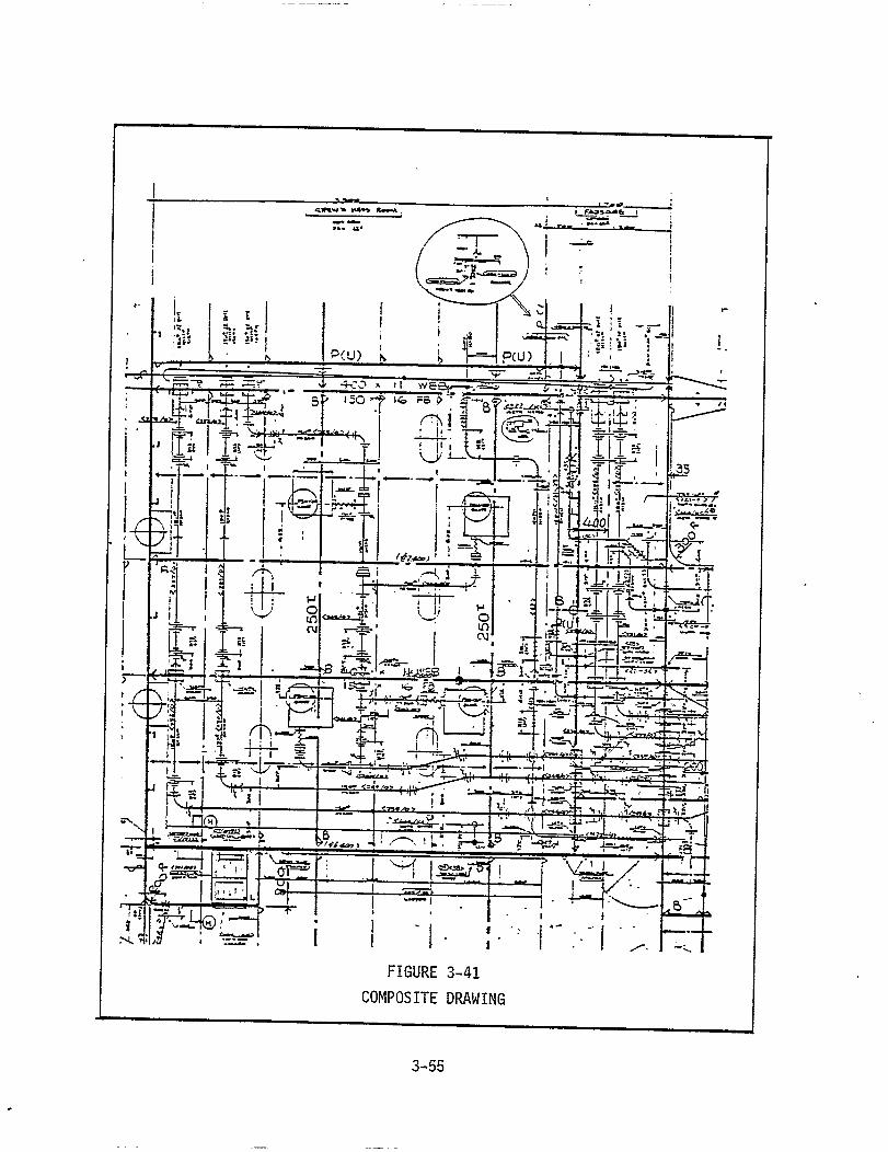
In addition to the above, the Detail Design effort also produces
composite drawings showing the layout of all outfitting material in
specific "Work Zones" (a further breakdown of the outfitting zones
into small packages of outfitting work). These composite drawings
show the interrelationship of the many different systems integral
to the individual work zones together with details of mounting and
joining. Figure 3-41 provides an example of a composite drawing.
Upon completion of the composite drawings the final stage of
design, Work Instruction Design, is initiated. This design stage
produces drawings of outfitting components which are to be installed
3-52

MATFRIAL LIST FOR PIPE
MLP
OUTFITTING MATERIALDESCRIPTION S NO CODE C NO CODE WEIGHT
15A 94 161001 1 13 0 93.7
25A 94 161003 1 31 0 414.3
40A 94 161005 1 26 0 556.3
50A 94 161006 1 14 0 408.9
65A 94 161007 1 9 0 369.8
15B 94 162001 1 1 0 7.2
25B 94 162003 1 9 0 127.2
40B 94 152005 1 14 0 315.7
65B 94 162007 1 5 0 260.8
25C 94 162103 1 1 0 18.0
40C 94 162105 1 6 0 180.5
50C 94 162106 1 4 0 164.1
65C 94 162107 1 3 0 193.0
25CC 94 162118 1 1 0 18.0
40BB 94 162156 1 2 0 45.1
50BB 94 162157 1 2 0 59.8
65BB 94 162158 1 1 0 50.2
25CC NK 94 172022 1 2 0 35.0
40CC NK 94 172024 1 3 0 90.3
40CC AB 94 178024 1 1 0 30.1
40SC LR 94 184077 1 1 0 30.1
15B AB 94 188004 1 1 0 7.2
25B NK 94 188006 1 2 0 28.3
94
94
94
TOTAL 94 3,499.6
FIGURE 3-40
MATERIAL LIST (MLP)
3-53

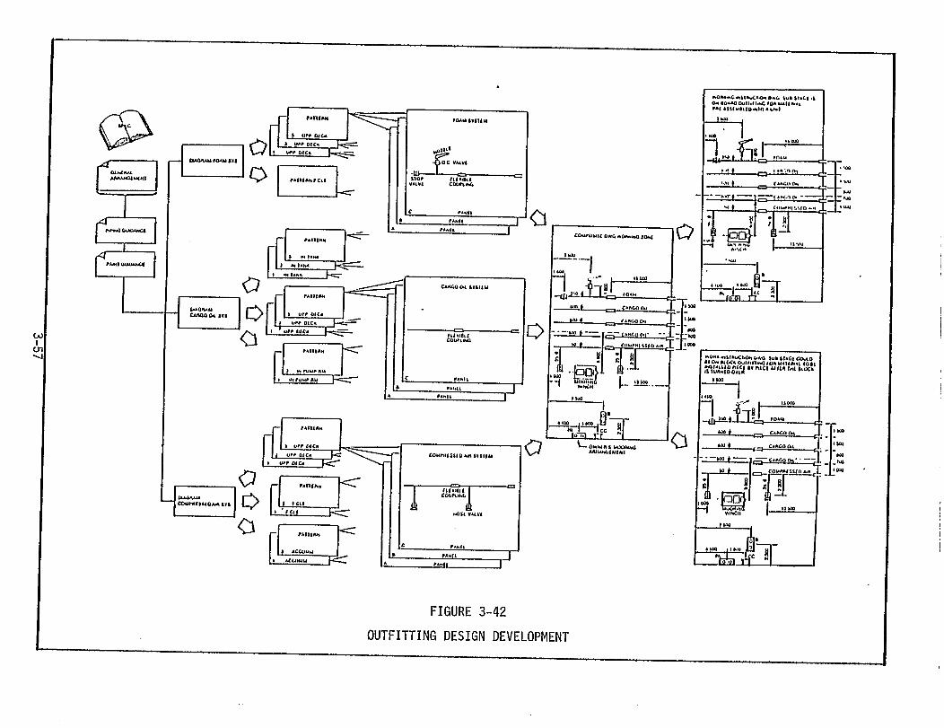
at di f ferent product ion s tages , e .g . , sub-assembly , assembly , e rec t ion
a f t e r l a u n c h . F igure 3 -42 i l lus t ra tes th i s deve lopment f rom top- leve l
design data to individual Work Instruction Drawings. Accompanying
these drawings is another material list, the Material List for Fitting
(MLF) which corresponds to the work to be accomplished at the production
stage shown on the Work Instruction Drawing. This package of informa-
tion describes the work to be done, the production stage at which it is
to be done, and the list of materials which must be accumulated and
present at the work site. Figures 3-43 and 3-44 provide examples of
a Work Instruction Drawing and a Material List for Fitting, respectively.
The Work Instruction Drawing, the associated MLF, the procured
components and the manufactured components (i.e. by the yard) comprise
a specific work package or "pallet" as it is defined by IHI. All
information and all related material is collected at the proper work
site, at the proper production work stage, and at the proper time
interval to enable the outfitting of specific units or on-board the
erected ship.
The "pallets" of information and material correspond to the "work
zones" established for a given outfitting zone. These outfitting
activities are rigorously scheduled to continuously parallel the hull
construction sub-assembly, assembly and erection schedules.
Physical material is indeed "palletized" in the above system.
Pallets of pipe and other outfitting components are organized by pipe
shop and warehousing personnel and are transported to the outfitting
area as required by the outfitting schedules. This "kitting" of
material greatly facilitates the outfitting activities occurring at
3-56


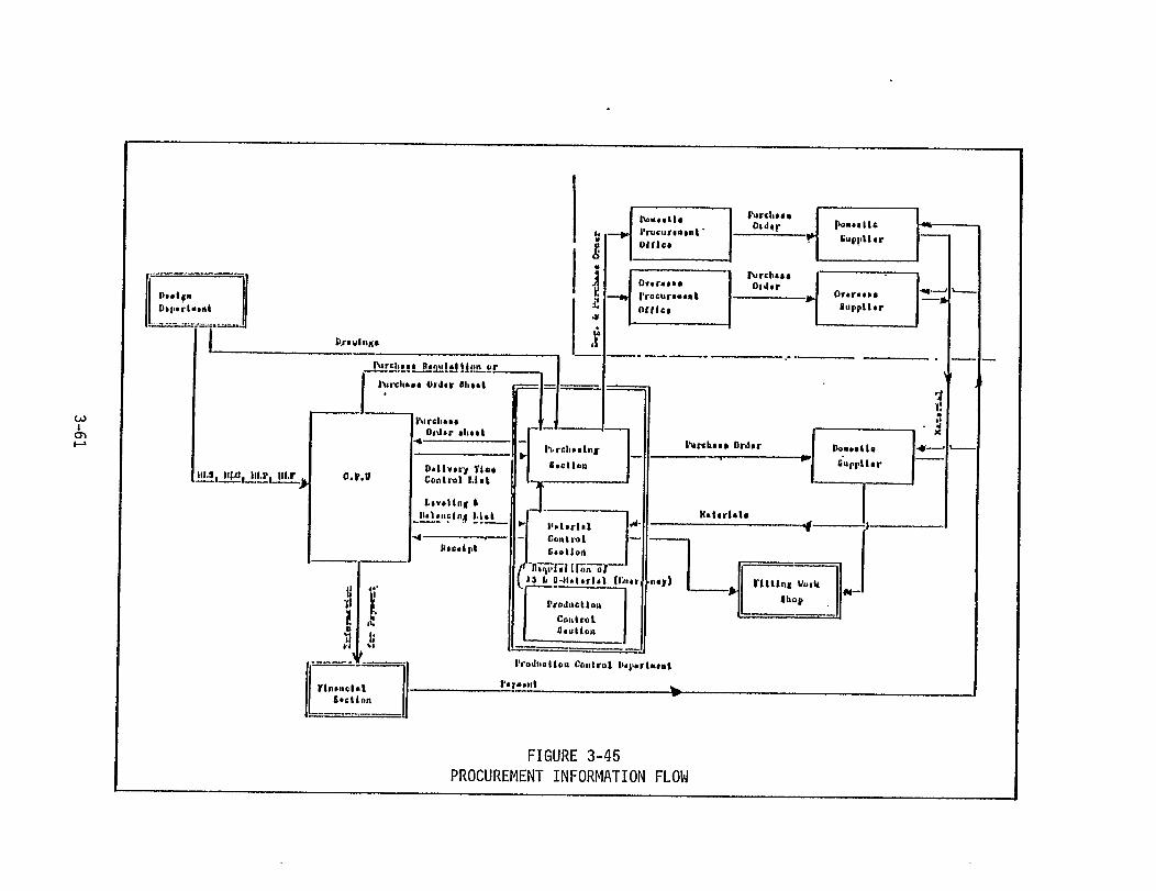


and disbursement. The purchasing activity naturally precedes the other
material control functions working parallel with the design development
and production planning to identify and procure vendor-supplied material
early in the program.
Material deliveries occur throughout the ship construction process
at appropriate times to support hull construction and outfitting. One
of the objectives of the material procurement activity is to maintain
deliveries at an even level so that the yard is never over-stocked
with steel or outfitting components.
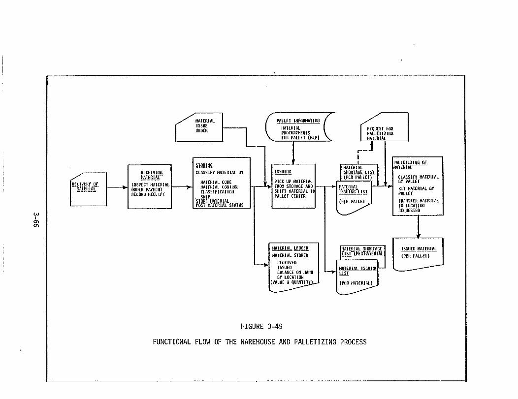
Upon delivery of material, the warehousing and palletizing process
begins. Figure 3-49 illustrates this process. Overall the process is
similar to the material receipt, storage and disbursement activities
common to most shipyards. In typical fashion the material is received,
inspected,
area. The
identifies
in a Mater
recorded and stored in an appropriate warehouse or storage
material is
its use for
al Ledger.
appropriate MLF is referenced and
classified by a specific code number that
a particular hull and the material is recorded
Upon receipt of a Material Issue Order the
Zone is released to a palletizing
several pallets. Materials lists
all material for a particular Work
area for collection into one or
are checked as material is loaded
into the pallets and any shortages are noted and forwarded to an
Expediting activity (in the Purchasing Department) for immediate
action. After all material (except that noted on shortage lists) has
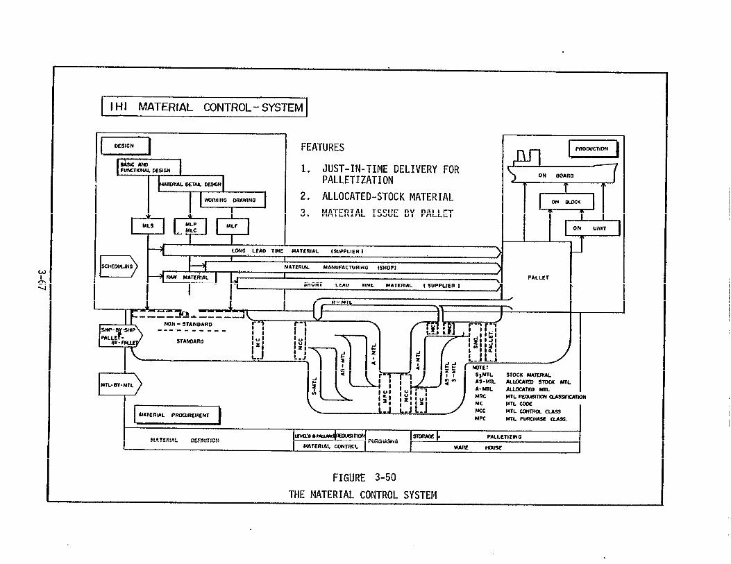
been collected, the pallets are transported to the appropriate
outfitting area. Figure 3-50 depicts this entire design, procurement
and outfitting process.
3-65

3.3.4 Production
The Fitting Workshop performs the actual fabrication of the manu-
factured outfitting materials and components except for those procured
from outside sources, and physically installs these components in
sub-assemblies, units and on-board the erected ship. This workshop
is organized to parallel the major outfitting zones of each ship except
for pipe and electrical which work across the outfitting zones. This
organization is shown in Figure 3-51.
The production flow of outfitting work is a combination of design,
procurement, manufacture of outfitting components and sub-assemblies
in the yard, and the installation of components (both yard-manufactured
and purchased) into units and on-board ship during erection and after
launch. These numerous activities are carefully scheduled in a de-
scending hierarchy of schedules from an overall master outfitting
schedule to weekly schedules prepared by the Fitting Workshop Planning
and Engineering Staff. Figure 3-52 depicts this production flow of
outfitting activities as they proceed in parallel with the building
of the hull construction units.
During the fitting process it is critical that the material and
the appropriate information in the form of material lists, drawings
and schedules flow together to the particular building stage and sub-
stage. Since some of the fitting material is manufactured internally,
not only the fitting schedules must be developed, but also the manu-
facturing schedules which provide the requisite material must be pre-
cisely developed to support the outfitting requirements. These manu-
facturing schedules are developed from the fitting schedules and
"set back" to provide sufficient manufacturing and palleting time
3-68
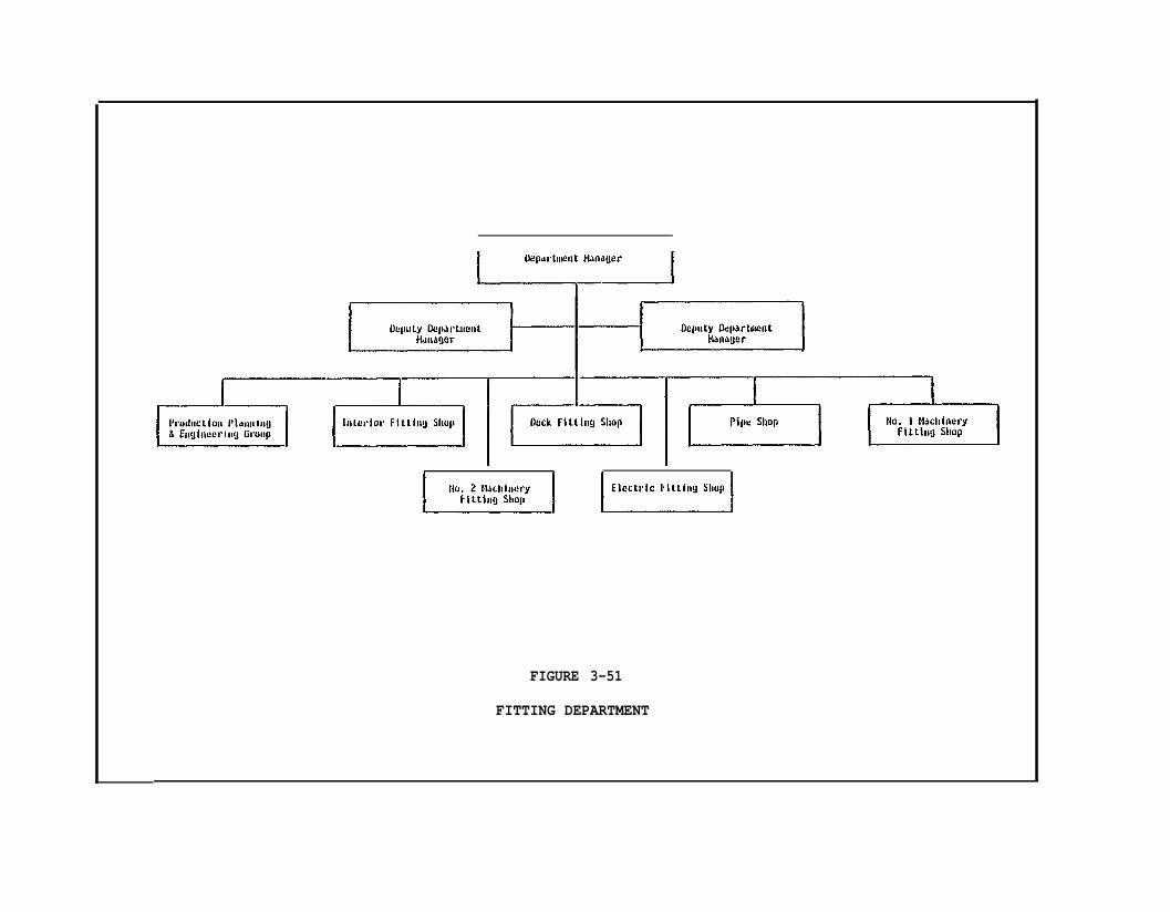
FIGURE 3-51
FITTING DEPARTMENT
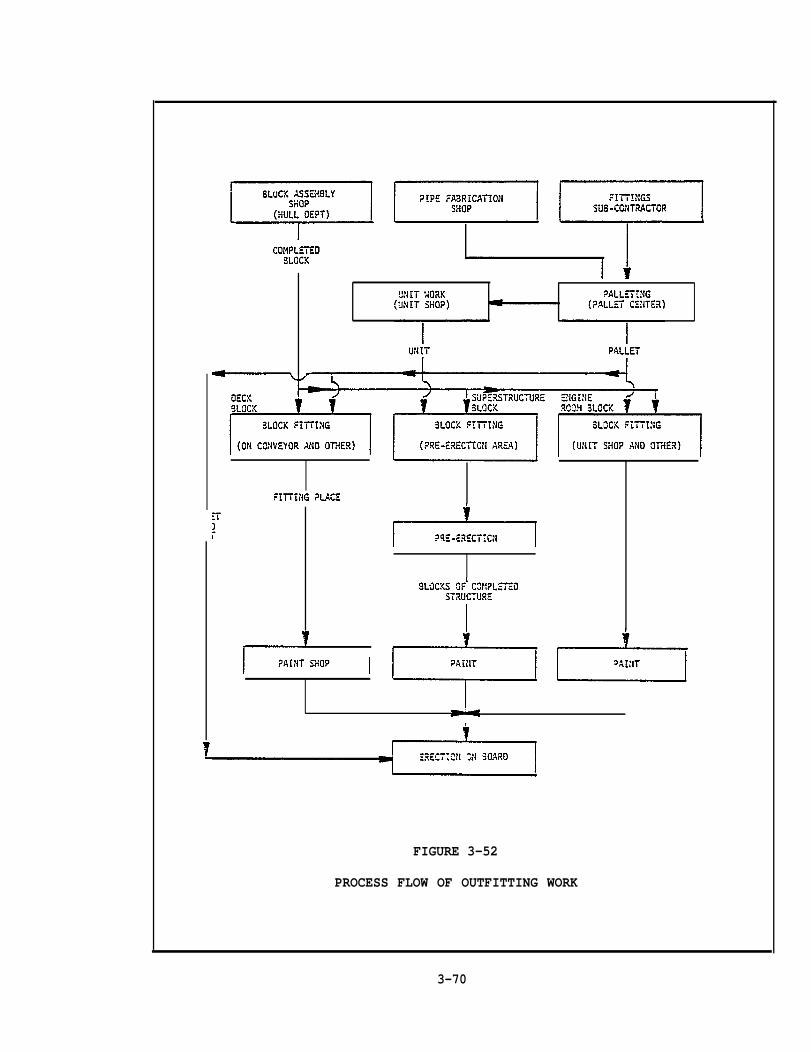
FIGURE 3-52
PROCESS FLOW OF OUTFITTING WORK
3-70

for all pipe pieces and other manufactured components. Figure 3-53
illustrates the flow of materials
outfitting system.
Engineering data development
and associated
continues well
struction program with the documentation of MLF,
data through the
into the ship con-
drawings and test
methods for the production stages of erection and post-launch. At
each stage of production specific data are required for the outfitting
activities for each unit or ship system (in the completed ship).
Figure 3-54 provides examples of the data required at each production
stage.
3.3.4.1 Pipe Shop
By far the most involved activity in the area of the manufacture
of outfitting components is related to the fabrication of pipe and
piping sub-assemblies. As explained above, the scheduling of this
activity is critical to the supply of outfitting components to the
fitting areas at the proper production stage of the hull units.
Also, because of the many diverse parts and pieces of the piping
arrangements, this activity must be carefully planned to avoid
delinquencies and schedule slippages.
To assure that the pipe fabrication
and executed,
IHI to direct
the essential
scheduling of
data flows to
a Pipe Fabrication Control
process is adequately planned
System has evolved within
this important production element. Figure 3-55 shows
elements of this system. As shown in the figure, the
raw material together with the appropriate engineering
the pipe shop in a precise and controlled manner. The
pipe is fabricated, bent, flanged and made ready for allocation to a
specific pallet. The material is then held in pallets until required
3-71

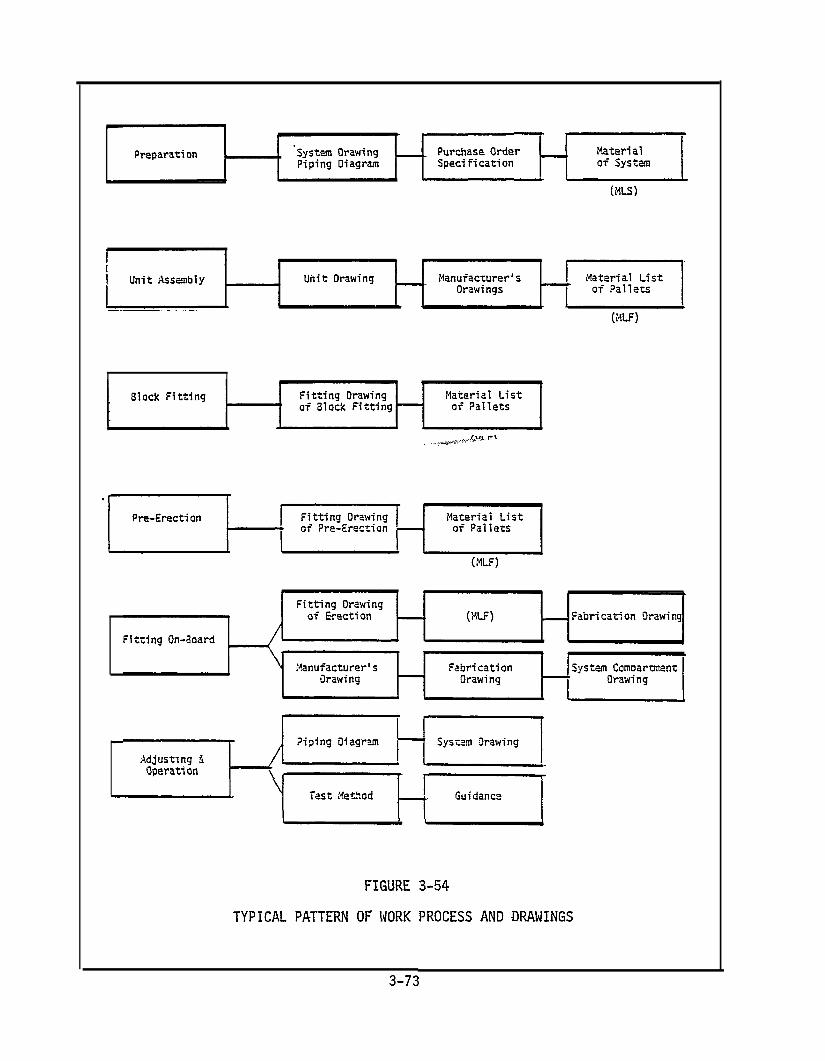
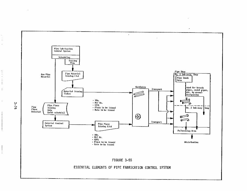
at a specific time at a particular outfitting area. Figure 3-56
defines the schedules, lists and drawings required to support this
process.
3.4 ADDITIONAL PLANNING
The Hull Construction and Outfit planning discussed in the fore-
going pages combine the aspects of design and production into a
thoroughly defined set of working drawings and plans necessary for the
manufacture of the hull units, the outfitting of those units and the
erection and outfitting of the entire ship. This discussion has pur-
posely omitted some types of planning (that occur simultaneously) in
order to simplify the production planning process. However, it is
important to cover these other planning aspects to complete the over-
view of this involved process.
Throughout the planning occurring in the breakdown of the hull
into its constituent bits and pieces and the outfit planning, a staff
of Accuracy Control Engineers assists the planners and designers and
formulates discrete accuracy control requirements for each unit,
sub-assembly and piece part. These engineers develop detailed data
concerning the vital dimensions and points of measurement to ensure
that all manufactured components of the ship meet the highest
accuracy standards possible. Additionally, these engineers develop
a plan or scheme for providing added material at each stage of pro-
duction to ensure that errors can be corrected without rework of
the part and to provide for neat cutting at the various sub-assembly,
assembly or erection stages. Accuracy Control Engineers also define
the base lines which must be used for unit alignment to keep
3-75
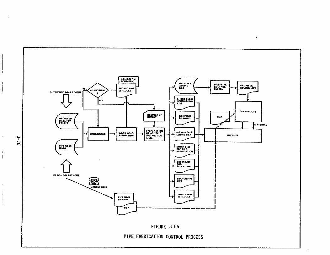

maximum accuracy throughout the production, assembly and erection
processes. The selection and application of process standards to the
fabrication processes is also the responsibility of these engineers.
The objective of this accuracy planning is to effect the highest
production efficiency by ensuring that each of the fabricated and
assembled components meets prescribed standards and therby requires
no re-work as the material flows through the production process. This
achievement of high accuracy reduces the amount of work required at
the erection stage and ensures that the completed ship will meet or
exceed all quality standards and will be in true alignment as required
by design specifications.
The details of this accuracy control planning are contained in
two Technology Transfer Program Reports: Livingston’s Final Report
on Quality Assurance, No. L2123-5.1-4-1, and the Special Report on
Accuracy Control Planning for Hull Construction, No. L2123-5.1-4-2.
Other plans are prepared by workshop staff personnel to detail the
methods for facilitating work during the erection stage and during
on-board outfitting. This planning is called "Field Planning" and
consists of the following types of plans.
Plan
Plan
Plan
Plan
PI an
Plan
Planini
for temporary holes (in the hull during erection)
for ventilation and cooling of the hull on the ways
for supply of electrical power and gas lines
for stools arrangement on the ways
for equipment access on-board and on working staging
for standard shipwrighting techniques
for maintaining shaft alignment considering thetial hogging of the aft and forward ship sections
3-77

Plan for tank arrangement and testing
Plan for final dimension check items
Plan for disposal of temporary pieces for construction
Examples of these types of plans are presented in Appendix E.
3-78

SECTION 4
THE IHI SCHEDULING SYSTEM
4.1 GENERAL
The IHI scheduling system is a delineated hierarchy of schedules
descending from the customer delivery requirement to the lowest working
levels.
unique;
parison
The methods used by IHI in this scheduling system are not
however, some of the techniques are somewhat different in com-
to U.S. practice.
Basically, the system begins with the delivery schedule established
by the Head Office. This schedule is reviewed in some detail by the
Production Control staff of the shipyard selected to build the ship
and can be adjusted if found to be impracticable. If the yard can
accommodate the ship in the time established by the Head Office, the
Production Control group (in the shipyard’s General Superintendent’s
office) formulates a Ship Construction Master Schedule which places
the total building period into context with all other construction
work in the yard. Placement of a new
Construction Master Schedule is based
and personnel to accomplish the work
ship program into the Ship
on availability of facilities
in the desired time frame.
The Ship Construction Master Schedule becomes the guiding master
schedule for the development of all lower tier schedules and is re-
garded as the one absolute and inflexible schedule throughout the
building process.
Figure 4-1 presents
from this primary master
Major Milestone Schedule
the hierarchy of schedules which are developed
schedule. The next schedule prepared is the
which defines the time period designated in
4-1


the Ship Construction Master Schedule for construction of a particular
ship or ships in terms of key events such as planning, fabrication
start, keel laying, launch and delivery. Other key events that normally
constrain the ship construction process, such as delivery of main
engines or other long lead-time items that are procured from outside
sources, may also be included. This schedule provides information for
the construction of the Erection Master Schedule.
The Erection Master Schedule prescribes the sequence to be followed
in the build-up of the ship in the building basin. The several major
zones of the ship (i.e., mid-body, bow, stern and house) are separately
scheduled and each of the units comprising these zones are scheduled
individually for the precise time of landing in the basin. This
erection schedule allows for the completion of all on-board outfitting
work subsequent to the landing of the final unit on the erected ship.
A precise set of standards is used to calculate the landing and joining
of each unit to adjacent units already in the basin. These time
standards dictate the amount of time required between each unit, and
the schedule is developed as a series of "set backs" from the final
unit in each zone.
Based on the mandatory erection time requirements for each unit,
the Assembly Master Schedule is prepared. This Master schedule estab-
lishes the periods for assembly of each unit sufficiently ahead of the
erection schedule to permit unit outfitting and transportation to
buffer storage or to the building basin platen areas.
From the Assembly Master Schedule detailed subordinate schedules
for hull fabrication, sub-assembly, assembly and erection are prepared.
4-3
These schedules are developed by the Production Planning and Engineering
groups of the Hull Construction Workshop in conjunction with the appli-
cable Section Managers and Foremen in the respective production stages
and areas.
In the fabrication area specific sub-schedules are developed for
the activities of the mold loft and for marking, cutting and bending
of all materials for each of the hull units. In the sub-assembly area,
schedules are prepared for the common or ordinary sub-assemblies (such
as webs) which are typical to many units and for more complex sub-
assemblies containing ducting or major frame components.
Detailed assembly schedules are prepared for each hull unit.
Due to the different process lanes through which the flat versus
curved units emerge, these schedules are prepared for each type of
unit with somewhat different information presented thereon. Schedules
are prepared for typical flat units (e.g. flat double bottom units),
semi-flat units (e.g. curved shell and curved internal structure
mounted on a flat panel such as the side double bottom units), bent
or curved units (e.g. bow or stern units), and joined units (e.g. two
units joined to allow the landing of a larger unit during erection).
The Erection sub-schedules detail the preparation, transport,
buffer storage, and final erection of each unit in the building basin.
All of the above schedules are primarily concerned with the hull
construction effort. In parallel with this effort, a series of out-
fitting schedules are prepared based on the Ship Construction Master
Schedule and the hull construction schedules as they are developed
for each stage of production.
4-4

After development of the Major Milestone Schedule, the Outfitting
Milestone Schedule is prepared by the Production Planning and Engineering
Group in the Fitting Workshop. This schedule expands the key milestones
shown in the Major Milestone Schedule to include the periods where the
fitting of the outfitting zones of the ship must begin and end. Other
key events, which coincide with the receipt of major purchased equip-
ment, are defined to indicate the completion of outfitting on critical
sub-assemblies or units of the ship which will constrain the start of
erection or the erection of specific units during the erection process.
The Outfitting Milestone Schedule provides the basis for develop-
ment of the Outfitting Master Schedule. This schedule must of course
coincide with the Assembly Master Schedule to allow proper time inter-
vals for the installation of outfitting sub-assemblies and components
during the build-up of each hull unit. Unit assembly instruction plans
are carefully studied to
the outfitting area, and
individual components or
assembly) into the unit.
Once the Outfitting
determine the time requirements for outfitting,
whether it
outfitting
would be more efficient to install
sub-assemblies (e.g. a piping sub-
Master Schedule has been developed, the
detailed subordinate schedules are prepared. Individual schedules
for the build-up of sub-assemblies of outfitting components (called on-
unit outfitting), for the fitting of both these sub-assemblies and
individual outfitting components in the hull units and for installation
of other sub-assemblies or components on-board the erected ship are
then constructed for each group of fitting personnel based on the
fitting tasks to be accomplished in order to execute the individual
4-5

sub-schedules. These work schedules cover each month of the Outfitting
Master Schedule and each week of each monthly schedule. These weekly
schedules prescribe the task, the personnel and the time allowed for
each outfitting activity each day.
In this descending hierarchy of schedules both the hull construc-
tion and the outfitting tasks are developed and sequenced to coincide
with one another and with each higher level schedule. The Ship Con-
struction Master Schedule usually contains only two weeks slack time
which can be used to accommodate any unanticipated delays. This
obviously requires careful and comprehensive schedule planning at each
level of schedule development and a total commitment by all personnel
to meet schedule dates once they are developed. The use of overtime is
permitted in order to maintain schedule position, but unless overtime
is purposely included in the schedules (by top-management decision)
the use of overtime is restricted to the most dire circumstances.
This description of the IHI schedule system provides only a brief
overview of this complex and highly refined scheduling process. The
following paragraphs provide a more detailed description of each of
the schedules in this system.
4.2 SHIP CONSTRUCTION MASTER SCHEDULE
The Ship Construction Master Schedule is the top-level construction
schedule for all work in a given yard. When a new ship or ship program
is introduced into a yard a suitable time frame must be allocated to
its construction within the overall building schedule of the yard and
with
This
yard
due regard to the delivery schedule established by the Head Office.
schedule is prepared by the Production Control Group of the ship-
through an estimation of the required man-hours per month based
4-6
on the through-put rates established for the yard facilities and work-
force. This estimate is compared to the manpower available at specific
times in the overall building schedule of the yard and times are ad-
justed to provide sufficient manpower for the construction task.
Naturally many considerations are necessary to the fixing of the appro-
priate time period, especially if the yard is heavily loaded with work.
However, the primary basis for the establishment of this schedule is
the availability of manpower. Figure 4-2 depicts the requisites and
flow of development of the Ship
4-3 provides an example of this
4.3 MAJOR MILESTONE SCHEDULE
Construction Master Schedule. Figure
type of schedule.
Figure 4-2 also shows the development of the Major Milestone
Schedule as a continuance of the Ship Construction Master Schedule.
This combined development is necessary to properly refine both sched-
ules in an iterative process that takes into consideration the major
constraining events to the ship construction cycle. These events
typically portray keel laying, launch, sea trials and delivery, but
may also be expanded to show other major events such as the landing
of the main engines or receipt or installation of critical purchased
items. Depending on the amount of work in the yard these schedules
can be simple or elaborate as deemed necessary to delineate clearly
mandatory scheduled events. Figure 4-4 shows an example of this
Major Milestone Schedule.
4.4 ERECTION MASTER SCHEDULE
The Erection Master Schedule is the first working schedule pre-
pared. This schedule establishes the erection times for each unit in
each zone of the ship. The ship is typically built up from the mid-ship
4-7
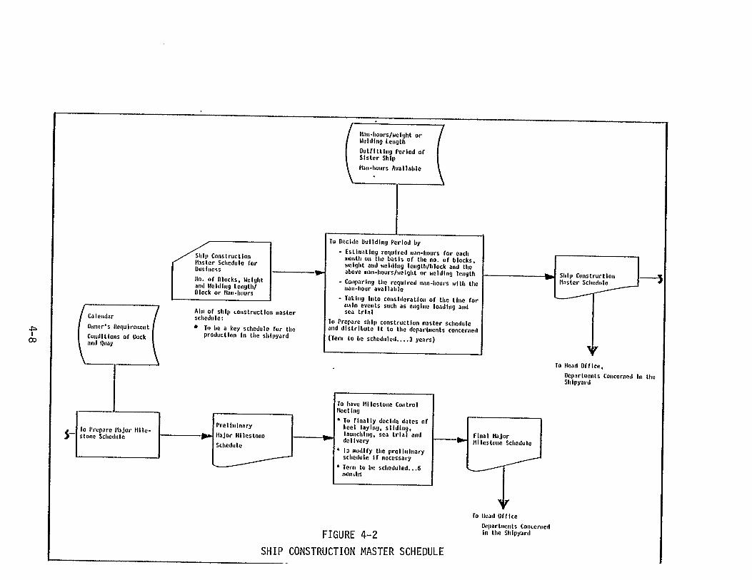
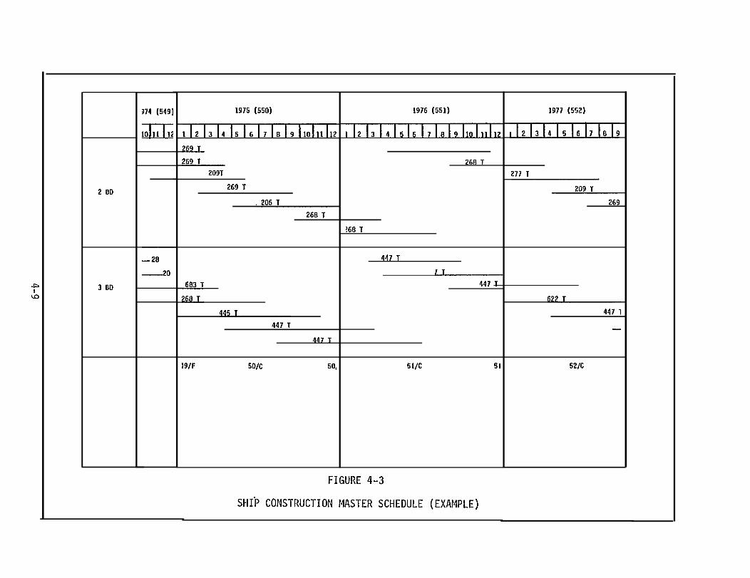

sections starting with the first center bottom units just forward of
the engine room. Bow and stern sections will be started subsequent
to the joining of the bottom midship sections and the build-up will
proceed in all three zones according to the erection sequence estab-
lished in the Erection Master Schedule.
This schedule establishes the requirements for completed units
which must be either in buffer storage, in storage in the building
basin platen area, or being completed in time for direct movement to
the building basin and immediate erection. This schedule is therefore
structured taking account of the following:
1. Proper erection sequence
2. Erection process
3. Capacities of assembly yard
4. Capacities of storage yard
5. Crane Capacities
6. Capacities of outfitting and painting shops
7. Capacities of erection work groups
The objective of this scheduling activity is to maintain the best
possible balance among all of these elements while preserving a good
erection sequence and schedule within the total ship construction
time frame. Figure 4-5 provides an example of the Erection Master
Schedule.
4.5 ASSEMBLY MASTER SCHEDULE
The Assembly Master Schedule is prepared to show the time require-
ments for each unit during the assembly process. Each type of unit
is sorted by the type of fabrication process required for its production
4-11
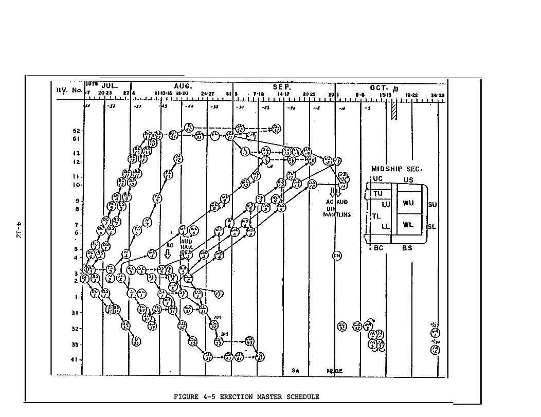
FIGURE 4-5 ERECTION MASTER SCHEDULE
into the following:
Flat Units (e.g. center double bottom units of the midship section)
Semi-flat Units (e.g. side double bottom units)
Curved Units (e.g. bow and stern sections)
Joined Units (e.g. two or more units joined to form a "Grand Unit"
After sorting of the units into the above categories a "latest comple-
tion schedule" is determined for each unit using the formula C = E - A,
where:
C = Assembly completion date
E = Erection date
A = Advance days required for painting, outfitting, overturning,and joining with other units.
Using this formula, the latest completion date for each unit is computed.
The Advance Days required for additional work once the unit build-up
is complete is standardized as shown in Figure 4-6.
Once the latest completion date has been established for each
unit several other criteria are applied to arrange the units in a
proper sequence and flow to maintain a full load and smooth flow through
the assembly areas. These criteria are listed below.
1. Determination of the number of assembly days per unit
2. Assembly area requirements for each type of unit
3. Capacities of each process lane
4. Optimum manloading of each process lane
5. Outfitting requirements on units having major outfitting
6. Painting requirements
7. Storage requirements
8. Flow of structurally similar units in series
4-13

These considerations enter into the scheduling of each individual
unit and of each unit category. Every attempt is made to maintain a
smooth and even flow of materials through the production and assembly
process and to minimize the requirement to store a great many units
in buffer storage areas.
The number of required assembly days for the different types of
units is a standard in the yards. This standard is shown in Figure
4-7. Also the calculation of manloading is standardized through the
computation of weld deposit required on the various units. Weld deposit
(DM or Deposit Meters) per month per assembly area is plotted on a graph
and compared to the established capacity of that area. If the plot
shows that the scheduled work exceeds that of the established capacity,
work may be shifted to other assembly areas, subcontracted or, in
extreme cases, the erection date may be rescheduled. Figure 4-8 depicts
a plot of a proposed assembly schedule versus the established capacity
of a specific assembly area. Figure 4-9 provides an example of an
Assembly Master Schedule.
4.6 SUBORDINATE SCHEDULES
Using the information contained in the Assembly Master Schedule,
Hull Construction Workshop engineers prepare detailed schedules for
each sub-stage of the fabrication, assembly and erection stages. N o
overall schedule is prepared for each of the production stages; rather,
the schedules detail the required dates for lofting, marking, cutting,
bending, sub-assembly, etc., to meet the assembly dates established
in the Assembly Master Schedule.
All of this sub-scheduling is an iterative process which generally
4-15

PART UNIT ASSEMBLY JOIN
FORE Curved Skin 8Semi-Flat 7Pre-Ere. 15 - 20
Bottom 7 7-10Skin 7 7 - 10BilgeMID 7 10 - 15T. Bhd. 6L. Bhd. 6Deck 6 10
E/R Engine Bed 8 10 - 20Curved Skin 8Semi-Flat 7
Curved Skin 8AFT. Semi-Flat 7
Pre-Ere. 15 - 20
FIGURE 4-7
REQUIRED ASSEMBLY DAYS STANDARD PER HULL STRUCTURAL TYPE
4-16
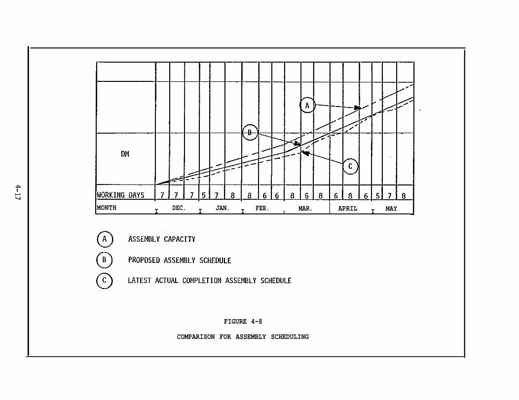
MONTH I DEC. I JAN. I FEB.I
MAR. I APRIL I MAY
FIGURE 4-8
COMPARISON FOR ASSEMBLY SCHEDULING

develops from the erection sub-schedule to the assembly sub-schedule
to the sub-assembly sub-schedule. However, because of the many con-
siderations of process times, manloading, maintenance of a continuous
production flow, storage of sub-assemblies and units, etc., it is
necessary to constantly adjust these schedules during their development.
All of the sub-schedules really work as a "set" of schedules which
detail the entire manufacturing process from start to finish.
4.6.1 Fabrication Sub-schedules
Detailed sub-schedules are prepared for each operation in the
fabrication process (i.e., lofting, marking, cutting, bending, and
sub-assembly). These schedules cover all of the work required for
each ship set of parts, pieces, and sub-assemblies. For example,
all of the work required by the mold loft is covered by one sub-
schedule, marking by another, and so on. Each of these schedules
is formulated taking into account the longer processing times of
certain components versus other more simple components. Parts requiring
mechanical and flame bending naturally require longer scheduling than
simply cut pieces. Therefore, these parts will be started into the
production process before the simpler pieces to assure that all re-
quired components are available in time to support sub-assembly or
assembly of a unit.
4.6.1.1 Mold Loft Schedules
Mold Loft schedules are prepared for each unit of a given ship.
The schedules define each day’s activity for the mold loft for each
unit. Lofting requirements are specified in the working drawings
and these requirements and the daily schedule are coordinated by the
Production Planning and Engineering group.
4-19
Precise lofting is considered vital to the "downstream" activities
of fabrication and assembly for a mistake in lofting is often not
recognized until parts have been fabricated and are being assembled.
Also, lofting is the pacing activity for the fabrication operations
and the careful and accurate scheduling of lofting activities is
considered one of the major prerequisites to the smooth flow of
material through the fabrication shops. Figure 4-10 shows an example
of a lofting schedule.
4.6.1.2 Marking , Cutting and Bending
These sub-schedules are developed for each of the different pro-
cess lanes of the fabrication shops. Basically there are four process
lanes used to process the different types of steel components: 1) a
lane for cutting of small pieces (e.g. internal structure members)
using N/C or manual methods; 2) a lane for cutting skin or panel
plates using a flame planer; 3) a lane for cutting and bending raw
shapes such as angles; and 4) a lane for bending skin and panel plates
for curved units. Each of these process lanes requires individual
schedules for marking and cutting. Bending schedules are prepared
for those lanes engaged in this activity.
These sub-schedules are prepared on the ultimate need date for
the components for sub-assembly or assembly, and the length of time
required to process bent or curved pieces versus simpler parts and
pieces. Consideration is also given to any pieces requiring special
cutting such as beveling which necessitates a longer process time and
which should be removed from the continuous process flow, and to
arranging a flow of similar or identical pieces through a given work
station to maximize the production rate (e.g. plates moving through
4-20


a flame planing station). Examples of the marking and cutting, and
bending schedules are presented in Figures 4-11 through 4-13.
4.6.1.3 Sub-Assembly
The breakdown of the units, performed during Block Assembly Plan-
ning, identifies the sub-assembly requirements for each unit. Using
this information and the Assembly Master Schedule, workshop engineers
develop the sub-assembly schedule for each block.
Sub-assembly of components allows a more gradual build-up of the
units in diverse areas and in a less comlex and more controllable
manner.
Sub-assembly of steel components is performed at the end of the
fabrication process lanes. The scheduling performed for components
undergoing fabrication is primarily oriented toward completing all
necessary components to support a smooth flow through the sub-assembly
process. Sub-assembly schedules are constructed so as to support
the assembly of units, just as the fabrication schedules support the
build-up of the sub-assemblies.
An important consideration in the formulation of the sub-assembly
schedule is the arranging of material flow so that identical sub-
assemblies can be processed one after another until that type of sub-
assembly is completed. This is not always possible due to the schedul-
ing requirements for other types of sub-assemblies to support the
assembly requirements of the units.
4.6.1.4 Assembly
Assembly sub-schedules are prepared for each type of unit i.e.
flat or curved, and for each assembly area and each sub-stage. The
Block Assembly Plans, Assembly Specification Plans and the Assembly
4-22
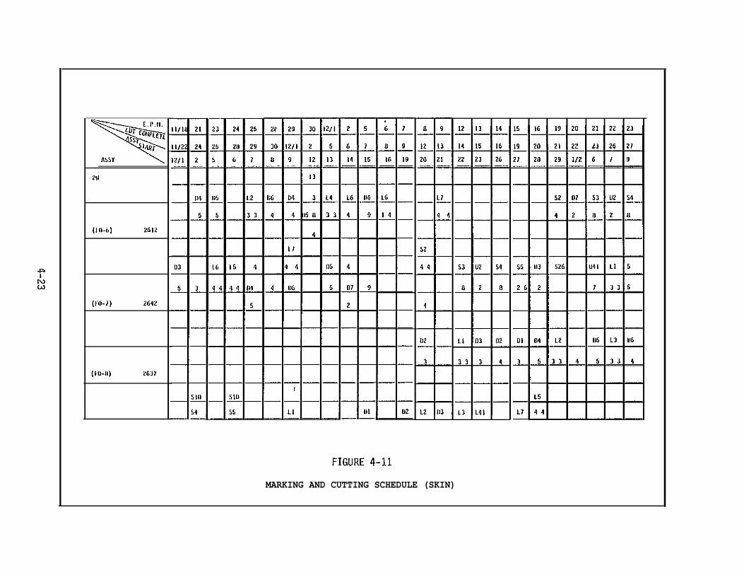
MARKING AND CUTTING SCHEDULE (SKIN)

FIGURE 4-12
EPM OR MANUAL MARKING AND CUTTING SCHEDULE (PARTS AND PIECES)


Master Schedule are the basis for these schedules.
The Assembly stage is divided into a series of sub-stages as
follows:
Assembly and welding of stiffened panels
Assembly and welding of frames, webs and other internalstructures
Assembly and welding of frames and webs to panels
Turning over of assembled blocks
Completion of welding
Fitting of frames, hanging pieces, scaffolding,outfittings, pipes, etc.
Painting
Each of these sub-stages is detailed for each assembly in the
sub-schedules. Production Planning and Engineering group personnel
develop the sub-schedules on the basis of the total welding require-
ments for each unit which also dictate the manloading for that assembly
area. The use of cranes is also carefully scheduled especially for
the heavy lifts after the units begin to be assembled.
Assembly scheduling is also concerned with the necessity to
store units prior to ship erection. Since space is nearly always
at a premium in the IHI yards, the storage of the large units can
cause serious problems and result in excessive transportation require-
ments or in the slow-down of assembly work because completed units
cannot be moved promptly. Ideally, units would be transported directly
to the building basin and immediately erected. However, this is not
possible due to the longer schedule time required for assembly versus
erection. Therefore, a considerable number of units are completed
and stored either on the basin platen area or in buffer storage areas
4-26
awaiting
erection
building
a smooth
erection
4.6.1.5
the start of erection. This provides sufficient time once
begins for following units to be completed and moved to the
site by the time they are to be erected. This method allows
flow of assembly units to the erection site throughout the
stage.
Erection
As in the Assembly Stage, the Erection Stage is divided into a
series of sub-stages detailing each step of the erection process.
These sub-stages are:
Unit Erection
Shipwrighting
Scaffold Erection
Main Structure Fitting
Main Structure Welding
Sub-structure Fitting
Sub-structure Welding
Cleaning
Internal Visual Inspection
Scaffold Removal
Water Tank Test
Completion
Erection is performed by zone or in the case of the cargo holds
by individual tank or hold.
The erection sub-schedules are developed in concert with the
Erection Master Schedule by detailing the steps involved in prepara-
tion, landing and joining the individual units either one at a time or
4-27
after being joined into a combination of units which are landed as a
composite into the basin.
Fitting and welding manhours are calculated for each step in the
erection sequence and the steps are "set back" from the preceding step
the appropriate number of days to allow for the accomplishment of the
requisite tasks. When completed the schedules are adjusted to coincide
with
next
tied
ship
the launch of the ship and with the start of the erection of the
ship scheduled for that building basin.
Schedules for the disassembly of erection scaffolding are closely
to both the schedule of inspection and the schedule for final
painting.
Examples of sub-assembly, assembly and erection schedules are
provided in Appendix F.
4.7 OUTFITTING SCHEDULING
In parallel with the scheduling of the steel work through the
Hull Construction Workshop, outfitting scheduling is developed to
reflect the procurement, fabrication, sub-assembly and installation
of outfitting components. The schedules coincide with the various
production stages of hull work as it proceeds through the sub-assembly,
assembly and erection process. Outfit scheduling is critical to the
completion of hull units and must be carefully organized to avoid
the interruption of the flow of work to the building basin.
The schedules prepared for outfitting are: the Outfitting Mile-
stone Schedule; the Outfitting Master Schedule; Master Schedules for
On-unit, On-block and On-board Outfitting; and Monthly and Weekly
Shop Schedules. Figure 4-14 depicts this hierarchy of outfitting
schedules.
4-28
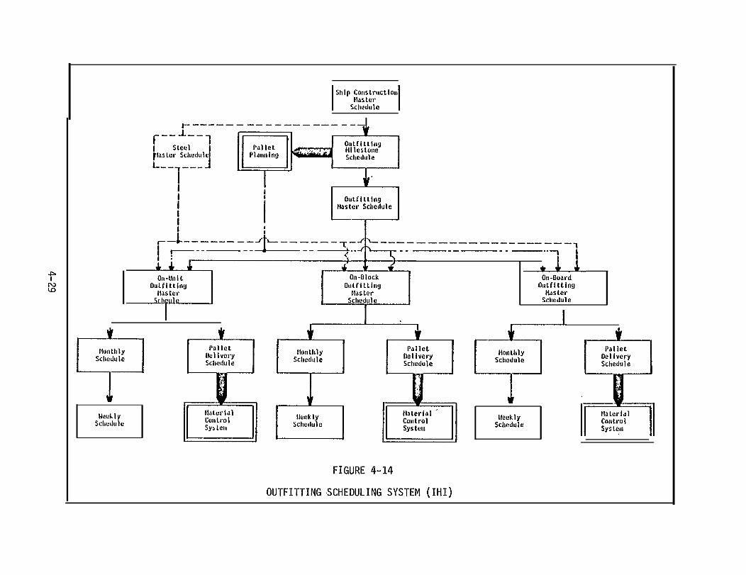

4.7.1 Outfitting Milestone Schedule
The objective of this schedule is to coordinate the principal
outfitting requirements with those of hull construction and painting.
Table T4-1 provides an indication of the types of milestones plotted
in this schedule.
This schedule is prepared by the Production Planning and Engineer-
ing group in the Fitting Workshop and coordinated with the staff group
of the Hull Construction Workshop. Each of the Fitting Shop Managers
approves the scheduling of the milestones in his respective area and
subsequently the schedule is reviewed and approved by the Managers of
Hull Construction and Painting.
Figure 4-15 depicts the development of the Outfitting Milestone
Schedule including the information required for its development and
its distribution. Figure 4-16 provides an example of this schedule.
4.7.2 Outfitting Master Schedule
Based on the milestones established in the Outfitting Milestone
Schedule, the Erection Schedule and the Master Assembly Schedule,
the outfitting Master Schedule is prepared. The objective of this
schedule is to establish firm dates for the build-up of outfitting
sub-assemblies, the installation of these sub-assemblies and other
outfitting components on the unit assemblies, and/or on-board the
erected ship. The schedule contains the milestone events previously
scheduled in the Outfitting Milestone Schedule and "set back" dates
for the step-by-step activities required to achieve the scheduled
event. Manpower availability is thoroughly investigated to ensure
that sufficient manpower is available to accomplish the required
outfitting as developed on the schedule. Dates may be adjusted in
4-30
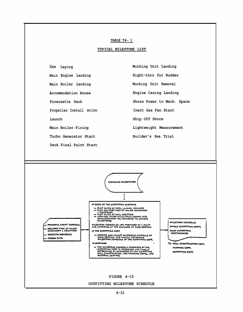
Main
Main
Laying
Engine Landing
Boiler Landing
Accommodation House
Forecastle Deck
Propeller Install
Launch
ation
TABLE T4- 1
TYPICAL MILESTONE LIST
Main Boiler Firing
Turbo Generator Start
Deck Final Paint Start
Working Unit Landing
Sight-thru for Rudder
Working Unit Removal
Engine Casing Landing
Shore Power to Mach. Space
Inert Gas Fan Start
Ship Off Shore
Lightweight Measurement
Builder’s Sea Trial
FIGURE 4-15
OUTFITTING MILESTONE SCHEDULE
4-31


the case where manpower is not sufficient to accommodate the scheduled
work.
Since all Fitting groups will be performing some type of work
in many different areas during the execution of this schedule, the
managers of each group review and approve the schedule of the work
for their group. Figure 4-17 shows the development of this schedule
and Figure 4-18 provides an example of the completed schedule.
4.7.3 On-Unit, On-Block and On-Board Master Schedules
A further breakdown of the Outfitting Master Schedule is made to
isolate the distinct activities of outfitting concerned with the
build-up of outfitting sub-assemblies (on-unit), the outfitting to be
accomplished on the hull units (on-block), and the outfitting to be
performed on-board the erected ship. Each of these production stages
is covered by a separate schedule which is used by the outfitting
section managers in creating the detail working schedules for their
respective sections.
4.7.4 Working Schedules
Section Managers prepare two types of schedules to control and
allocate resources to the individual jobs which must be performed by
their sections. Each manager prepares a "Monthly" schedule which really
encompasses the work to be accomplished over the next two month period.
These schedules identify the outfitting activities which must be per-
formed, the times at which pallets must be ordered to support those
activities and to schedule fitting personnel for the different tasks.
This schedule is prepared by a staff engineer, but is ultimately used
by individual foremen within each fitting section and acts as a per-
formance control chart in that each month’s progress is measured
4-33

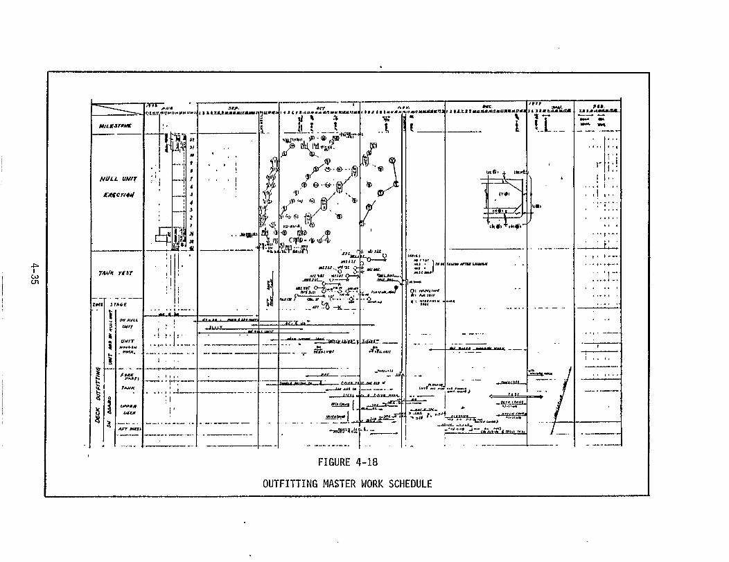

during the preparation of each subsequent month's schedule. Figure
4-19 depicts the development flow of these monthly schedules.
The second working schedule is prepared weekly on the basis of
the monthly schedule for each section. This schedule is prepared by
an Assistant Foreman and approved by the Foreman. The weekly schedule
covers a two week period but is up-dated every week. The schedule is
simply a more definitive breakdown of the activities shown on the
monthly schedule and designates the day-by-day personnel assignments
and tasks to be performed. Figure 4-20 illustrates the development
of these schedules.
4.7.5 Pipe Fabrication Scheduling
The Pipe Shop is responsible only for the fabrication of pipe.
Fitting work involving pipe is the responsibility of the other fitting
groups. Because the fabrication of pipe to support the various fitting
schedules is so critical specific pipe shop schedules are prepared.
These schedules identify the pipe requirements for specific pallets
as required by the MLF and the Outfitting Master Schedules. Pipe is
then categorized by type or "family" and scheduled in "long-term" and
"short-term" schedules. The development of the two different schedules
is shown in Figures' 4-21 and 4-22.
4-36


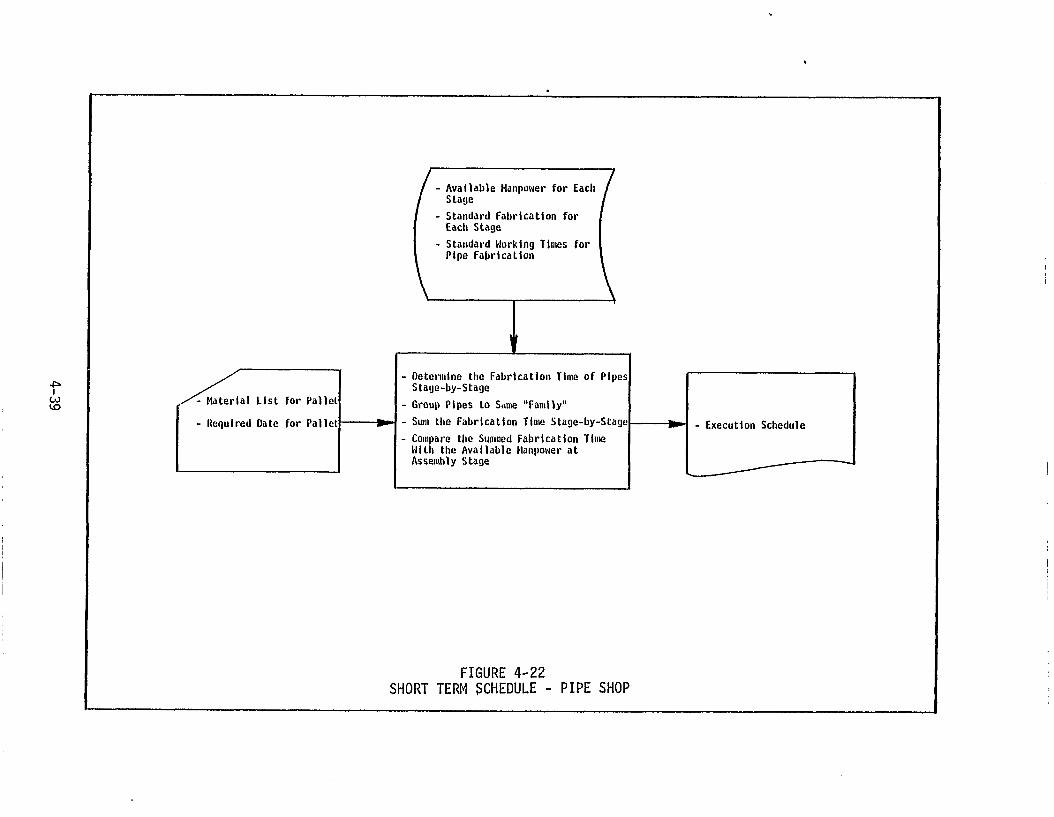

SECTION 5
MANPOWER PLANNING
5.1 GENERAL
Manpower planning in IHI is a precise method of applying personnel
resources to each task of the well defined production process. The
planning accomplished for hull construction and outfitting and the
exact scheduling of these activities provides the framework for the
application of manpower in discrete stages, sub-stages and time periods.
The entire production process is organized around the "process
lanes" system. As previously discussed in Section 2, this system allo-
cates specific types of work to particular work stations established
in a fixed location within one of several process lanes. In Hull
Construction these work stations are related to lofting, marking,
cutting, bending, sub-assembly, assembly and erection. The activities
of each of these work stations is defined in great detail in the plans
prepared prior to the start of fabrication, and further delineated in
the detailed schedules discussed in the previous section. The organi-
zation of the basic production system and this highly refined planning
and scheduling allows the application of personnel to small increments
of work at fixed times throughout the hull production process.
In outfitting the same basic methodology is applied although the
locations and mix of personnel vary according to the type of outfitting
being accomplished. Also, the fabrication of pipe is a discrete
planning and scheduling effort of its own and the application of man-
power is determined separately from that of hull construction and out-
fitting.
5-1

The computation of manpower in each of these major areas of hull
construction, outfitting and pipe fabrication is based to a large
extent on the historical data accumulated by the various yards from
the prior construction of similar ships. This historical data has
cataloged production rates per manhour in terms of weight of steel,
weld metal deposited, cutting length, outfitting component weight and
manhours required for sub-assembly or installation, painting and pipe
fabrication. The application of these data to the same type of opera-
tions ship after ship is a routine and accurate process.
The concept of accuracy control plays an important part in the
estimation and allocation of manpower to the specific tasks and areas
of the production system. Because of the emphasis placed on accuracy
control by the IHI yards and because of the continual improvement of
accuracy in the production activities, the estimation of manhours for
each production process is very precise. Under the concept of accuracy
control it is assumed that few errors or discrepancies will exist in
the processed material as it moves from work station to work station.
Errors or discrepancies in workmanship are nearly always discovered in
the area where they occur and are repaired prior to leaving that work
station. This means that only the work programmed for a given work
station need be performed at that work station. No rework or correc-
tion of defects passed on by a prior work station is necessary. This
allows very accurate man-loading of each work station area.
5.2 BUDGET PLANNING
The budget planning process in IHI is not unlike that utilized
in U.S. yards, although the participation of the workshops planning
5-2

staffs is a unique aspect and indicates that workshop managers
participate more fully in the establishment of their budgets than
their U.S. counterparts.
Essentially, the overall budget is established by the IHI Head
Office and refined by the shipyard General Manager into working budgets
for each department in each workshop. This refinement of the overall
budget is accomplished both by the Production Control Department which
is staff to the General Manager, and by the Production workshops. The
estimate generated by Production Control is in more general terms and
is based primarily on historical data collected from previous ship
construction programs. Production department estimates are in precise
terms of numbers of welding and fitting manhours required per day/week/
month.
Subsequent to the initial estimation of manhours by Production
Control and the production shops, a Budget Meeting is held and a de-
cision as to the operating budget is made by the General Manager. This
operating budget is then issued by Production Control to the various
cost centers in the yard. No adjustment of the budget is made until
one or two months before ship delivery. This adjustment is made on
the basis of accumulated manhour expenditures at another meeting of
Production Control, the affected shop(s), and the General Manager.
Figure 5-1 shows this budgeting process.
5.3 SPECIFIC MANPOWER PLANNING METHODS
The manpower planning process involves several distinct steps to
ascertain the precise numbers of the different types of personnel
required for hull construction and outfitting. Essentially, this
5-3


planning evolves from an overall estimate of the manhours required for
each production stage (i.e., lofting, fabrication, assembly, erection,
outfitting) to a scheduling of these manhours on a month-by-month basis
and, by means of these man-loading schedules, to an
and allocation of appropriate personnel to the work
work station. Monitoring of these manhours is then
identification
groups at each
accomplished by
means of production control charts maintained by the workshop staff
groups.
5.3.1 Production Planning Estimate
The overall estimate of manpower is performed by the Production
Control Department by first breaking down the estimate into the three
main areas of hull construction, fitting and painting.
Using the ship specifications and a Budget Control List (prepared
from historical data) and additional historical data from similar
ships, the Production Control planners estimate the number of manhours
required for hull construction based on the weight of the hull, probable
welding lengths, and probable cutting lengths. Outfitting manhours
are estimated using the weight of fittings and the electrical cable
length. Main machinery weight is not included in this calculation.
Painting is estimated by weight and by the area requiring painting.
These manhours estimates are plotted in a series of curves which
are then aggregated in a "Production Curve" to show the total manhours
requirement for the ship over the time allocated in the Shipyard Master
Schedule for ship construction. Figure 5-2 shows the development of
this overall Production Curve.
5-5
--

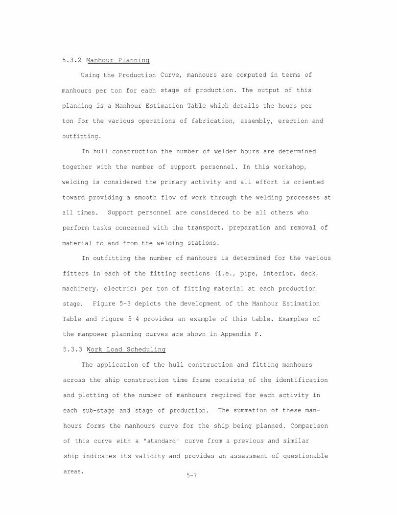
5.3.2 Manhour Planning
Using the Production
manhours per ton for each
Curve, manhours are computed in terms of
stage of production. The output of this
planning is a Manhour Estimation Table which details the hours per
ton for the various operations of fabrication, assembly, erection and
outfitting.
In hull construction the number of welder hours are determined
together with the number of support personnel. In this workshop,
welding is considered the primary activity and all effort is oriented
toward providing a smooth flow of work through the welding processes at
all times. Support personnel are considered to be all others who
perform tasks concerned with the
material to and from the welding
In outfitting the number of
transport, preparation and removal of
stations.
manhours is determined for the various
fitters in each of the fitting sections (i.e., pipe, interior, deck,
machinery, electric) per ton of fitting material at each production
stage. Figure 5-3 depicts the development of the Manhour Estimation
Table and Figure 5-4 provides an example of this table. Examples of
the manpower planning curves are shown in Appendix F.
5.3.3 Work Load Scheduling
The application of the hull construction and fitting manhours
across the ship construction time frame consists of the identification
and plotting of the number of manhours required for each activity in
each sub-stage and stage of production. The summation of these man-
hours forms the manhours curve for the ship being planned. Comparison
of this curve with a "standard"
ship indicates its validity and
areas.
curve from a previous and similar
provides an assessment of questionable
5-7
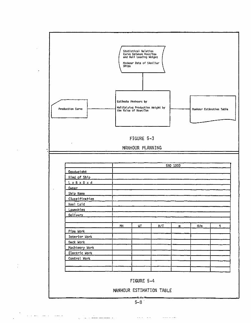
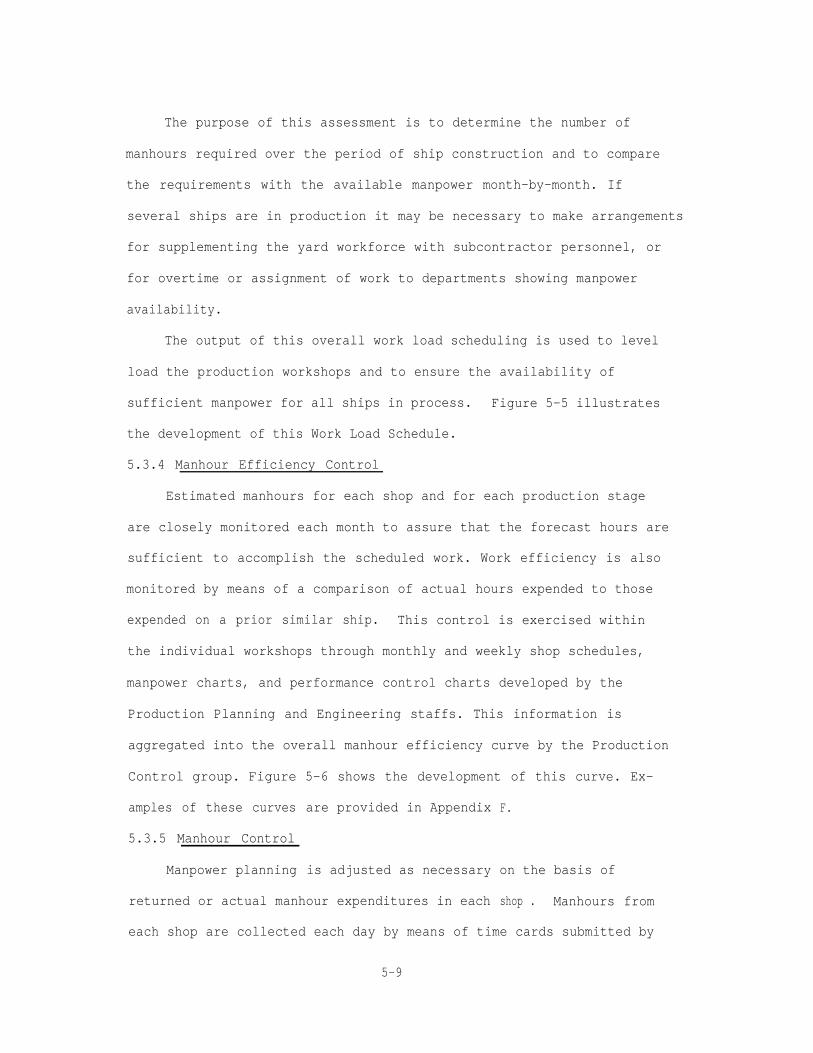
The purpose of this assessment is to determine the number of
manhours required over the period of ship construction and to compare
the requirements with the available manpower month-by-month. If
several ships are in production it may be necessary to make arrangements
for supplementing the yard workforce with subcontractor personnel, or
for overtime or assignment of work to departments showing manpower
availability.
The output of this overall work load scheduling is used to level
load the production workshops and to ensure the availability of
sufficient manpower for all ships in process. Figure 5-5 illustrates
the development of this Work Load Schedule.
5.3.4 Manhour Efficiency Control
Estimated manhours for each shop and for each production stage
are closely monitored each month to assure that the forecast hours are
sufficient to accomplish the scheduled work. Work efficiency is also
monitored by means of a comparison of actual hours expended to those
expended on a prior similar ship. This control is exercised within
the individual workshops through monthly and weekly shop schedules,
manpower charts, and performance control charts developed by the
Production Planning and Engineering staffs. This information is
aggregated into the overall manhour efficiency curve by the Production
Control group. Figure
amples of these curves
5.3.5 Manhour Control
Manpower planning
5-6 shows the development of this curve. Ex-
are provided in Appendix
is adjusted as necessary
returned or actual manhour expenditures in each
F.
on the basis of
shop . Manhours from
each shop are collected each day by means of time cards submitted by
5-9

the shop foreman. These manhours are entered into the computer system
and compilations are produced every ten days by cost center and by
shop. This output is used to prepare the Manhour Efficiency Curve and
the detail performance control curves for each shop and department.
Figure 5-7 depicts the cycle of time charge collection and usage and
Figure 5-8 provides an example of the time collection sheet used by
shop foremen. Examples of these curves are provided in Appendix F.
The entire manpower planning cycle extends from the overall plan-
ning accomplished to establish the shipyard and department budgets to
the manhour-plans of the individual foremen of each production area.
Manpower planning at the working levels consists of the identification
and scheduling of the work groups allocated either to the hull con-
struction work stations or to the fitting tasks in the outfitting
schedule. Manhours are continually weighed against the actual man-
hours used on previous ships and by the various factors of manhours/
ton, manhours per length of weld deposited, cut lengths, outfittings
weight, cable lengths, etc. This manpower planning, when combined
with the production planning and scheduling (discussed in Sections
2 and 3), forms a complete framework of data for the performance of
all work in each area of production.
5-11
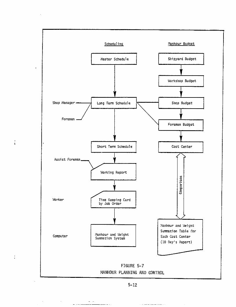


SECTION 6
PRODUCTION CONTROL
6.1 GENERAL
Production Control in the IHI yards happens as a natural consequence
of the production planning and scheduling system. The organization of
the hull construction and outfitting shops and activities, the detailed
planning accomplished for each of these activities and the use of work-
ing level schedules for small groups of personnel allows close monitor-
ing and control of each step of the production process.
Basically, three organizations are concerned with production
control: the Production Control Department and the Production Planning
and Engineering groups for the Hull Construction Workshop and the Fit-
ting Workshop respectively. This de-centralized control parallels
the de-centralization which characterizes the planning and scheduling
activities. The Production Control Department is primarily concerned
with the overall yard aspects while the Production Planning and Engineer-
ing groups are concerned with the detail control of the workshop activ-
ities.
The activities of these three groups start from the overall yard
planning and scheduling and descend to the levels of the individual
work stations. However, once production has begun, the daily inputs
from the working levels are coalesced into the control information
required to judge the status of the total program. In the planning
phase the production control system works from the top down, in the
production phase the system works from the bottom up.
6-1

6.2 PRODUCTION CONTROL DEPARTMENT
The Production Control Department is responsible to the shipyard
General Manager for the planning and scheduling of yard facilities and
manpower for all ships and other types of construction in process and
backlogged. This department prepares the Ship Construction Master
Schedule; accomplishes the planning of production functions in terms
of weight, cutting length, welding length, outfitting weight, cable
length, etc.; prepares
overall yard work load
control curves used to
trates this production
the overall yard manpower plans; prepares the
schedule; and prepares the manhour efficiency
monitor shipyard performance. Figure 6-1 illus-
control function.
This top-level planning and control is translated to successively
lower levels of the organization until each organization (i.e., workshop,
section, group) and each production stage (i.e., fabrication, assembly,
erection and outfitting) is fully detailed by planning, schedules and
performance control data.
Because of the thoroughness of the planning and scheduling,
usually only minor changes to the top-level plans and schedules are
required. If changes are required, they are generally accomplished
at the working levels such that the top-level plans are not affected.
Although the overall status of each program is closely monitored by
the Production Control Department, the majority of the actual production
control activity is performed by the workshop staff groups (i.e. the
Production Planning and Engineering groups).
6.3 PRODUCTION PLANNING AND ENGINEERING GROUPS
These groups, called the workshop staff groups, attend to a
6-2


multitude of planning, scheduling, coordination and control functions.
As previously mentioned, these groups are responsible for working with
design engineers in formulating the various plans and schedules to be
used throughout the production process. They also interface closely
with the foremen, Section Managers and the Production Control Depart-
ment in the preparation and updating of man-loading and performance
control charts and
Once the top-
Production Control
development of the
graphs.
evel shipyard planning is accomplished by the
Department, the workshop staff groups begin the
detailed plans and schedules for the actual opera-
tions of the various hull and outfitting groups. The wealth of plan-
ning data developed during the detail design process together with
the master schedules form the basis for the preparation of these
detailed shop and group plans and schedules.
Usually one member of the hull construction workshop staff group
is assigned responsibility for a particular sub-stage within the
fabrication, assembly or erection stages. This responsibility includes
working with the cognizant foreman in developing the detailed plans
and schedules for that area and preparation of performance control
graphs that will show the daily/weekly through-put rates, the weight
of steel processed, the length of weld metal deposited, and progress
achieved against schedule.
In the outfitting area, workshop staff personnel are assigned to
particular work groups concerned with the build-up of outfitting
component sub-assemblies, or on-block or on-board outfitting. The
tasks performed by these staff members are essentially the same as
6-4

those performed by staff members in the hull workshop. However, the
organization of the work, due to the many different jobs related to
outfitting versus the repetitive nature of hull construction, makes
the outfitting staff work far more variable. These differences are
discussed in the following paragraphs.
6.3.1 Hull Construction
Production Control of the various activities occurring in the Hull
Construction Workshop involves the planning and scheduling and subse-
quent monitoring and control of the manpower, processes and methods
utilized in these activities. The hull construction process, for
purposes of production control, is divided into the following areas:
Total hull, lofting, fabrication, sub-assembly, assembly and erection.
Within each of these areas several different means are established to
monitor production performance. Table T6-1 shows the various control
graphs prepared for each area. Examples of these graphs are provided
in Appendix F.
Prior to the preparation of the control graphs shown in the table,
the workshop staff engineers prepare sketches and a series of lists
detailing the weight of each hull block and the welding lengths in
specific assemblies or erection areas. These are:
Block Weight List
Welding Control Parameter Output List
Block DM List
Welding Progress Check Plan
The Block Weight List provides the total outfitted weight of
each block in the condition that it is to be erected. The list indi-
cates the blocks of the bow, stern, cargo hold section and the engine
6-5
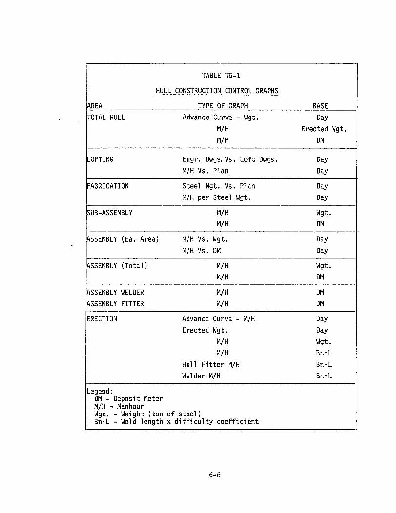
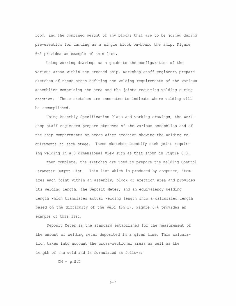
room, and the combined weight of any blocks that are to be joined during
pre-erection for landing as a single block on-board the ship. Figure
6-2 provides an example of this list.
Using working drawings as a guide to the configuration of the
various areas within the erected ship, workshop staff engineers prepare
sketches of these areas defining the welding requirements of the various
assemblies comprising the area and the joints requiring welding during
erection. These sketches are annotated to indicate where welding will
be accomplished.
Using Assembly Specification Plans and working drawings, the work-
shop staff engineers prepare sketches of the various assemblies and of
the ship compartments or areas after erection showing the welding re-
quirements at each stage. These sketches identify each joint requir-
ing welding in a 3-dimensional view such as that shown in Figure 6-3.
When complete, the sketches are used to prepare the Welding Control
Parameter Output List. This list which is produced by computer, item-
izes each joint within an assembly, block or erection area and provides
its welding length, the Deposit Meter, and an equivalency welding
length which translates actual welding length into a calculated length
based on the difficulty of the weld (Bn.L). Figure 6-4 provides an
example of this list.
Deposit Meter is the standard established for the measurement of
the amount of welding metal deposited in a given time. This calcula-
tion takes into account the cross-sectional areas as well as the
length of the weld and is formulated as follows:
DM = p.S.L
6-7

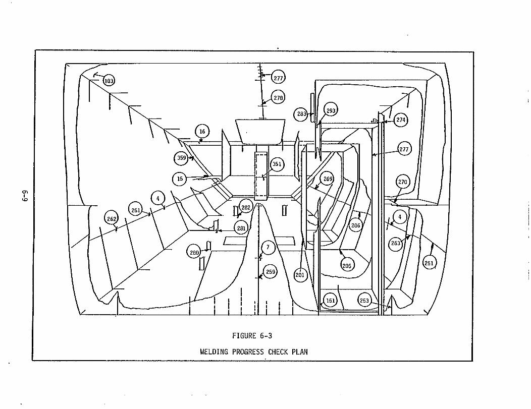


where: P = Constant
S = Sectional area of welding deposit
L = Welding Length
Bn.L is the modified or corrected welding length necessitated to
incorporate the varying degrees of complexity or difficulty inherent
in the welding processes during the erection stage. Bn.L is simply
calculated as follows:
Bn.L = L x D C
where: L = Welding Length
DC = Difficulty Coefficient
The Difficulty Coefficient is either an established standard de-
rived from work on prior similar ships or is assigned by the staff
engineer.
After the completion of the Welding Control Parameter Output List
the Block DM List is developed. This list provides an aggregate DM
for each block of the bow, stern, cargo hold section and the engine
room and will be used for progress measurement during the assembly
process. Figure 6-5 is an example of this list.
Using the Block Weight List, the Block DM List and the Welding
Control Parameter Output List, the workshops’ staff engineers prepare
the control charts applicable to their area of responsibility. The
majority of these control graphs reflect manhour expenditures versus
steel weight or DM per day per area. This actual data is contrasted
against the projections estimated for that area which will achieve
the required production rate and maintain the forecasted manpower and
schedule position. Since most of these control graphs are plotted
6-11
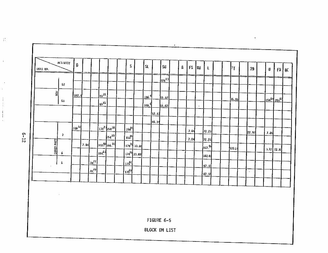

daily, deviations from projections are quickly recognized and corrective
action initiated.
In the areas of total hull progress and erection progress an
"Advance" curve is prepared to show the time intervals between the
stages of production (for the total hull) and between the fitters and
the welders during erection. In the case of the total hull advance
curve, the total weight processed during fabrication is plotted over
the time required for this processing. Then the total weight of the
steel processed during assembly and the total erected steel weight is
plotted over the time scheduled for each of these stages. Figure 6-6
shows an example of this type of curve.
The scheduled time between fitters and welders during the erection
process is also a critical schedule interval and is plotted on the
Erection Advance Curve. This application of personnel is especially
important when a series run of ships is in production. Figure 6-7
shows an example of this type of curve.
6.3.2 Outfitting,
As mentioned previously, outfitting activities parallel the hull
construction activities of sub-assembly, assembly and erection. With
the exception of pipe fabrication and painting, these activities
involve several or all of the fitting groups in the outfitting organi-
zation.
Although the outfitting organization is structured essentially
around the outfitting zones of the ship (i.e. Interior or Accommodations
Fitting group, Deck Fitting, No. 1 and No. 2 Machinery Fitting, and
Electric Fitting group) the man-loading and scheduling of the outfitting
6-13
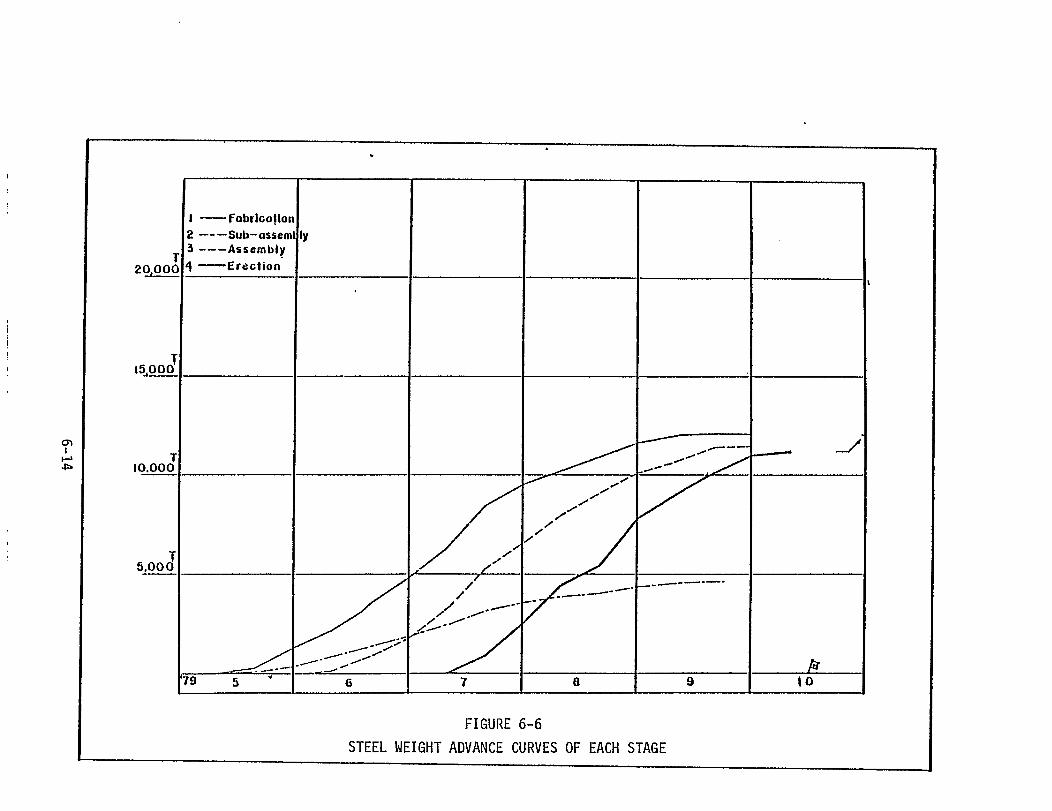

tasks is oriented toward On-unit (i.e. sub-assembly of outfitting
components), On-block and On-board activities. Hence, the outfitting
tasks require a blending of the skills of each of the organizational
groups into the type of work groups required for a given task. Also,
since the outfitting tasks are not of a repetitive nature (such as
those in hull construction) and since these tasks are performed in a
number of different locations, a distinctly different type of manhour
and schedule control is required.
In outfitting there is far more reliance on the use of the monthly
and weekly schedules than on performance control charts or graphs
although such control graphs are used to measure the progress of each
group.
As discussed in the Hull Construction paragraphs, Production
Control evolves from the top-level planning, scheduling and control
graphs to the successively lower levels of production. In outfitting
this top-level planning and control is manifested by the Shipbuilding
Master Schedule, the Outfitting Milestone Schedule, the Outfitting
Master Schedule and the corresponding shipyard and Outfitting Section
control charts. Beneath this level production control charts are
prepared to reflect progress of each work group during On-Unit, On-
block and On-board outfitting. Figure 6-8 illustrates this descending
hierarchy of controls and the correlation between these control charts
and the related schedules.
The primary measure of all of the top-level charts is the weight
of the outfitting components installed plotted against a constant time
base (i.e. day/week/month). Actuals are plotted against projections
6-16


to ascertain any discrepancies between manpower and schedule and to
take remedial action as necessary.
At the work group level control charts are precisely oriented
toward individual fitting jobs such as the installation of piping
in the engine room. In these cases performance control charts reflect
actual work accomplishment in contrast to the projected schedule.
Figures 6-9 and
the engine room
the actual work
6-10 show the schedule for the
(on-board) and the performance
accomplished, respectively.
installation of pipe in
control chart showing
The Production Planning and Engineering Group in the Fitting
Workshop prepares and maintains these schedules and control graphs,
and works with the respective foremen and section managers to adjust
any apparent deficiencies in schedules or man-loading.


SECTION 7
LEVINGSTON APPLICATION OF IHI TECHNOLOGY
7.1
has
GENERAL
During the course of the Technology Transfer Program, Livingston
adopted many of the IHI techniques of production planning and con-
trol. This has entailed a detailed study of the IHI system and a
careful evaluation of the parts of the system applicable to LSCo.
The principal difficulty in the institution of the IHI methodology
in another
techniques
of the IHI
shipyard is the fact that the IHI planning and scheduling
are built around the process lanes, sub-stages and stages
production
work groups and staff
work station or area,
planning, scheduling,
system. Also, the organization of personnel into
groups who are permanently assigned to a given
which greatly facilitates the implementation of
manloading and performance measurement data, is
generally absent in U.S. shipbuilding practice. Any attempt to employ
the IHI planning and production control techniques in a different type
of production system is extremely difficult and only marginally
effective.
As a result of the LSCo. studies,
the Livingston production system to an
the decision was made to convert
approximation of the IHI system
over a period of time and to initiate changes to the Livingston plan-
ning and scheduling system which would lead eventually to an IHI-type
system. All of the planning data originated for the first of the mod-
ified Future 32 bulk carriers being built by Livingston was converted
piece-by-piece to the IHI methods. Outfit planning, which had not
progressed far when this decision was made, was started using the IHI
7-1
techniques. Schedules were developed which
IHI and were adapted for use in conjunction
System. Also, the planning for the changes
paralleled those used by
with the LSCo. Work Order
required to the physical
plant were accomplished and work orders were issued to conform with
the modified flow of work through the facility.
In early 1980 Livingston began to modify its production system to
one using the concept of the "Process Lanes" system of IHI. To avoid
confusion during this period of re-organization the term "Gate System"
was adopted to describe the production system of LSCo. Essentially,
the system comprises a series of "gates" which are equivalent to the
IHI sub-stages and stages (i.e., plate cleaning, marking, cutting,
bending, sub-assembly, assembly, erection and the several outfitting
stages of sub-assembly of outfitting components, installation on
assembly units, and installation on-board the erected ship). Each of
these gates has an assistant foreman or foreman permanently assigned
and a number of worker personnel. The gates process steel according
to detail gate schedules to support the assembly, outfitting and
erection master schedules.
The implementation of the "Gate System" is far from complete at
this writing. The conversion of the production system in the midst of
producing the bulk carriers has been a formidable undertaking requiring
a gradual step-by-step transition from the old methods to the new.
The adaptation of the planning and scheduling data and the re-work of
the work order system to match the new planning was accomplished through-
out 1979. However, the modification of the physical plant to conform
to the requirements of the "gates" is still in work.
7-2
are
to
Several of the problems encountered by LSCo. during this transition
worthy of note. The physical facilities required a detailed study
dentify "gates" which would optimize material flow through the yard.
Once this study was completed, considerable reorganization and reloca-
tion of some facilites was necessary. Also, the new techniques adopted
for use in the system, such as flame bending, required new facilities
and areas within the new material flow lanes. This reorganization of
material flow necessitated the movement and restraining of personnel
and a re-routing of material from previously used processing and
storage sites. Movement and storage of components, sub-assemblies and
unit assemblies became a significant problem and buffer areas between
gates had to be developed to cushion the effects of the varying rates
of production through each of the gates.
At present the system is only partially installed and operable.
Several gates are functioning as true "gates", but many of the desirable
characteristics of a totally operating and highly perfected "process
lanes" system are still far in the future.
7.2 CHRONOLOGY OF THE LSCO. STUDY AND APPLICATION
The Technology Transfer Program was initiated simultaneously with
the start of construction of the modified Future 32 bulk carriers.
This, of course, did not allow for extensive prior study of the IHI
methods of planning which so strongly influence the development of the
detail and working level drawings. However, IHI consultants did join
the LSCo. design team shortly after the effort had begun.
Senior designers and planners in LSCo. had already determined
that the ship would have to be divided into manageable units which
could be fabricated individually on the slab areas of the existing
7-3
LSCo. facility. This had led to a breakdown of the ship which very
closely paralleled the Hull Block Planning of IHI. When the IHI
engineers joined the design team, some minor revisions of the unit
divsion were made. IHI documents describing the IHI Hull Block
Planning had been available to the LSCo. planners and the unit division
of Zone 1 (mid-ship section) of the ship essentially followed this
planning.
The LSCo.
ship breakdown
engineers had used specific criteria in determining the
for Zone 1. These criteria were:
1. Weight. It was decided to keep the units in the 40 to 50 ton
range to allow ease of handling by the gantry cranes which operated
parallel to the slab areas. From the General Arrangement drawing and
scantlings, the weight per foot of steel had been determined to assist
in deciding dividing points of the hull units.
less
U.S.
Zone
were
2. Available Material. The decision was made to keep the units
than 40'0" long since this length is the optimum mill length for
steel mills.
3. Natural Dividing Points. After studying the cross section of
1, it was noted that the watertight bulkheads between the holds
evenly spaced at 73'6" centers. This was divided in half and the
units were set at 36'9". The first unit was located in the center
under the first watertight bulkhead. Alternately, the units were
centered at the bulkhead and the units between the bulkheads were
centered on the hold. This arrangement did not exactly match the IHI
system where the first unit would have been started at the bulkhead
between the engine room and the first hold forward of the engine room;
however, some advantage was gained since only the four bilge units,
7-4
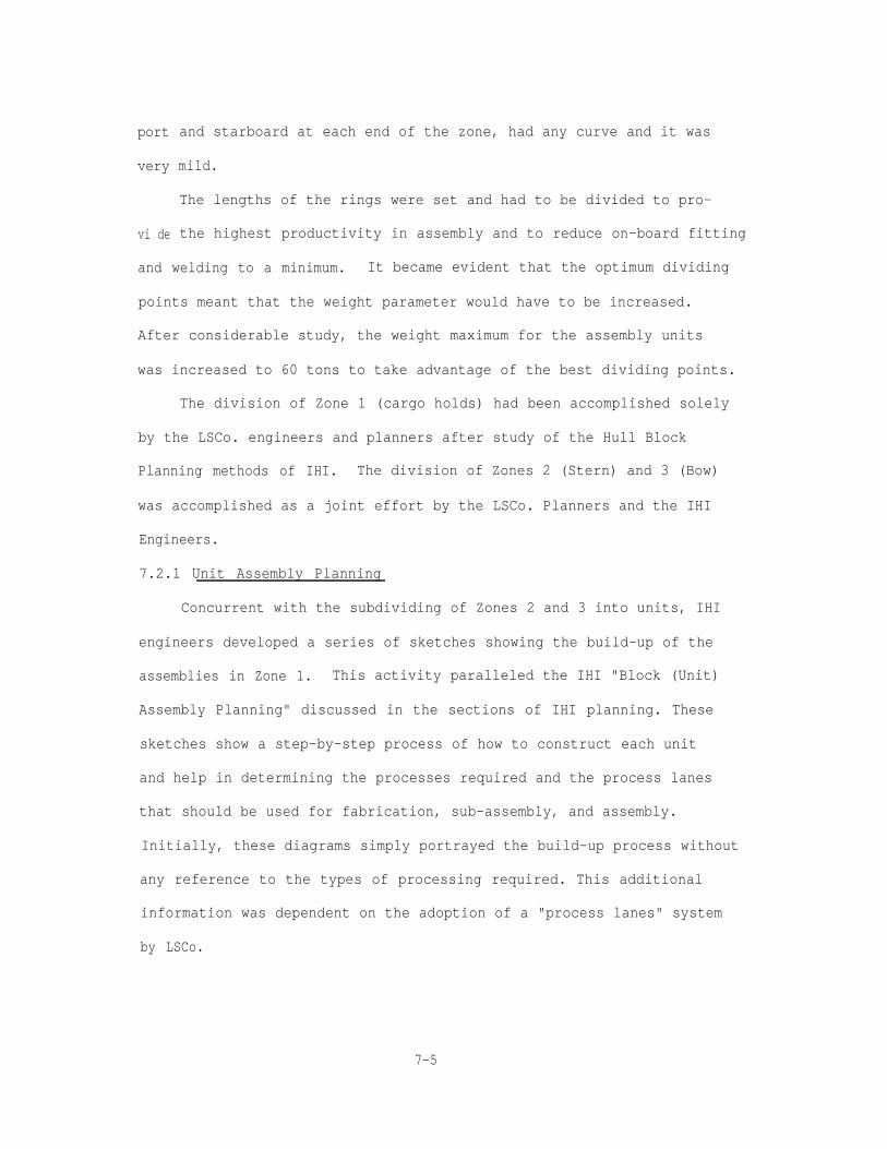
port
very
vi de
and starboard at each end of the zone, had any curve and it was
mild.
The lengths of the rings were set and had to be divided to pro-
the highest productivity in assembly and to reduce on-board fitting
and welding to a minimum. It became evident that the optimum dividing
points meant that the weight parameter would have to be increased.
After considerable study, the weight maximum for the assembly units
was increased to 60 tons to take advantage of the best dividing points.
The division of Zone 1 (cargo holds) had been accomplished solely
by the LSCo. engineers and planners after study of the Hull Block
Planning methods of IHI. The division of Zones 2 (Stern) and 3 (Bow)
was accomplished as a joint effort by the LSCo. Planners and the IHI
Engineers.
7.2.1 Unit Assembly Planning
Concurrent with the subdividing of Zones 2 and 3 into units, IHI
engineers developed a series of sketches showing the build-up of the
assemblies in Zone 1. This activity paralleled the IHI "Block (Unit)
Assembly Planning" discussed in the sections of IHI planning. These
sketches show a step-by-step process of how to construct each unit
and help in determining the processes required and the process lanes
that should be used for fabrication, sub-assembly, and assembly.
Initially, these diagrams simply portrayed the build-up process without
any reference to the types of processing required. This additional
information was dependent on the adoption of a "process lanes" system
by LSCo.
7-5

7.2.2 Process Lanes System
In May of 1979, the IHI consulting engineers presented a plan
that divided the construction area of the shipyard into "process lanes".
The basis for the division was the type of work to be done, the quantity
of the required work and the available facilities (especially the lift-
ing capacity of the cranes). The plan was accepted for implementation
by LSCo
facilit
by LSCo.
and a more intense study began to fit the system to the LSCo.
es. To avoid confusion between the IHI system and that adopted
the name "Gate System" was selected to describe the new system.
The LSCo. shipyard was already divided into "work stations" which
had been used to identify various process locations under the old ship
construction process used by the yard. These work stations were re-
organized to indicate work group locations within a specific "Gate".
The basic concept of the "Gate System" is the assignment of an
area(s) for specific types of work, or processes; the assignment of
a group of workers together with a foreman to a permanent area that
processes the same type of work regularly, so that planning and
scheduling becomes standardized and routine. Figure 7-1 depicts the
concepts of the Gate System throughout the shipbuilding cycle.
The division of the facilities began at the start of the fabrica-
tion process, layout and cutting. After material passes through the
painting process, it enters the "Gate System" and from that point
through other appropriate gates depending on whether it is a flat or
curved unit. After layout and cutting, the material passes into shaping
gates (if shaping is required) or into a gate specifically concerned
with sub-assembly. It next flows into component assembly gates and
eventually into one of several gates designated for final assembly.
7-6
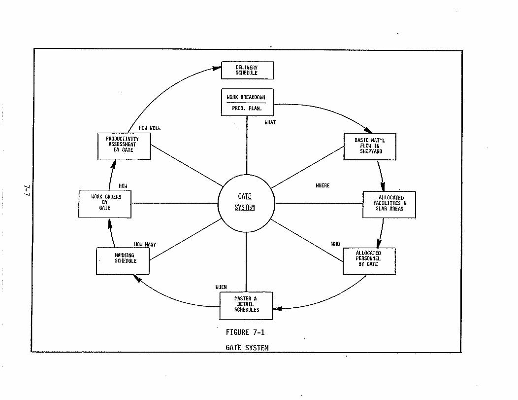
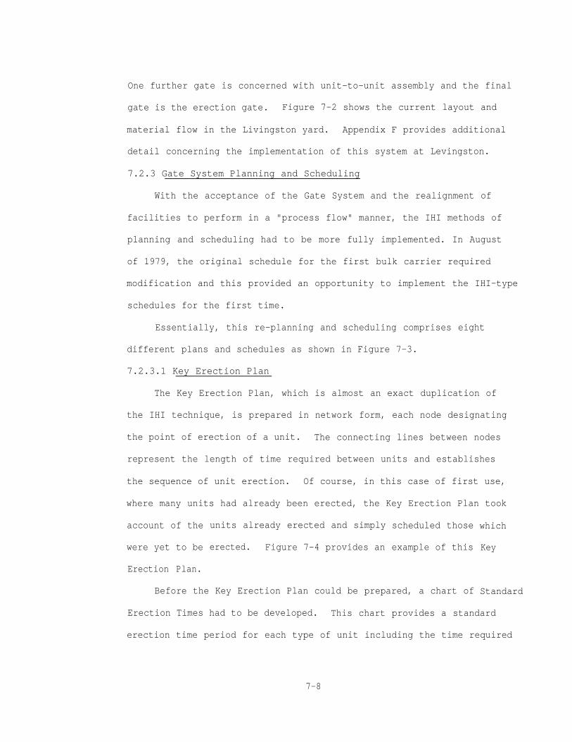
One further gate is concerned with unit-to-unit assembly and the final
gate is the erection gate. Figure 7-2 shows the current layout and
material flow in the Livingston yard. Appendix F provides additional
detail concerning the implementation of this system at Levingston.
7.2.3 Gate System Planning and Scheduling
With the acceptance of the Gate System and the realignment of
facilities to perform in a "process flow" manner, the IHI methods of
planning and scheduling had to be more fully implemented. In August
of 1979, the original schedule for the first bulk carrier required
modification and this provided an opportunity to implement the IHI-type
schedules for the first time.
Essentially, this re-planning and scheduling comprises eight
different plans and schedules as shown in Figure 7-3.
7.2.3.1 Key Erection Plan
The Key Erection Plan, which is almost an exact duplication of
the IHI technique, is prepared in network form, each node designating
the point of erection of a unit. The connecting lines between nodes
represent the length of time required between units and establishes
the sequence of unit erection. Of course, in this case of first use,
where many units had already been erected, the Key Erection Plan took
account of the
were yet to be
Erection Plan.
units already erected and simply
erected. Figure 7-4 provides an
scheduled those
example of this
Before the Key Erection Plan could be prepared, a chart of
Erection Times had to be developed. This chart provides a standard
which
Key
Standard
erection time period for each type of unit including the time required
7-8

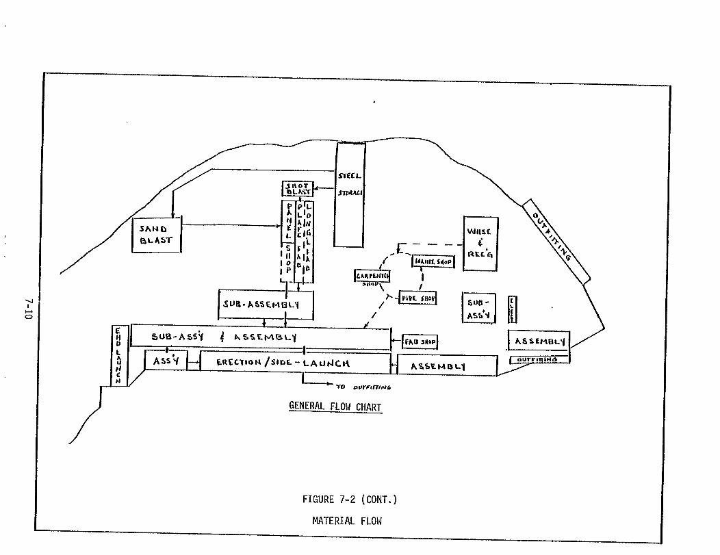
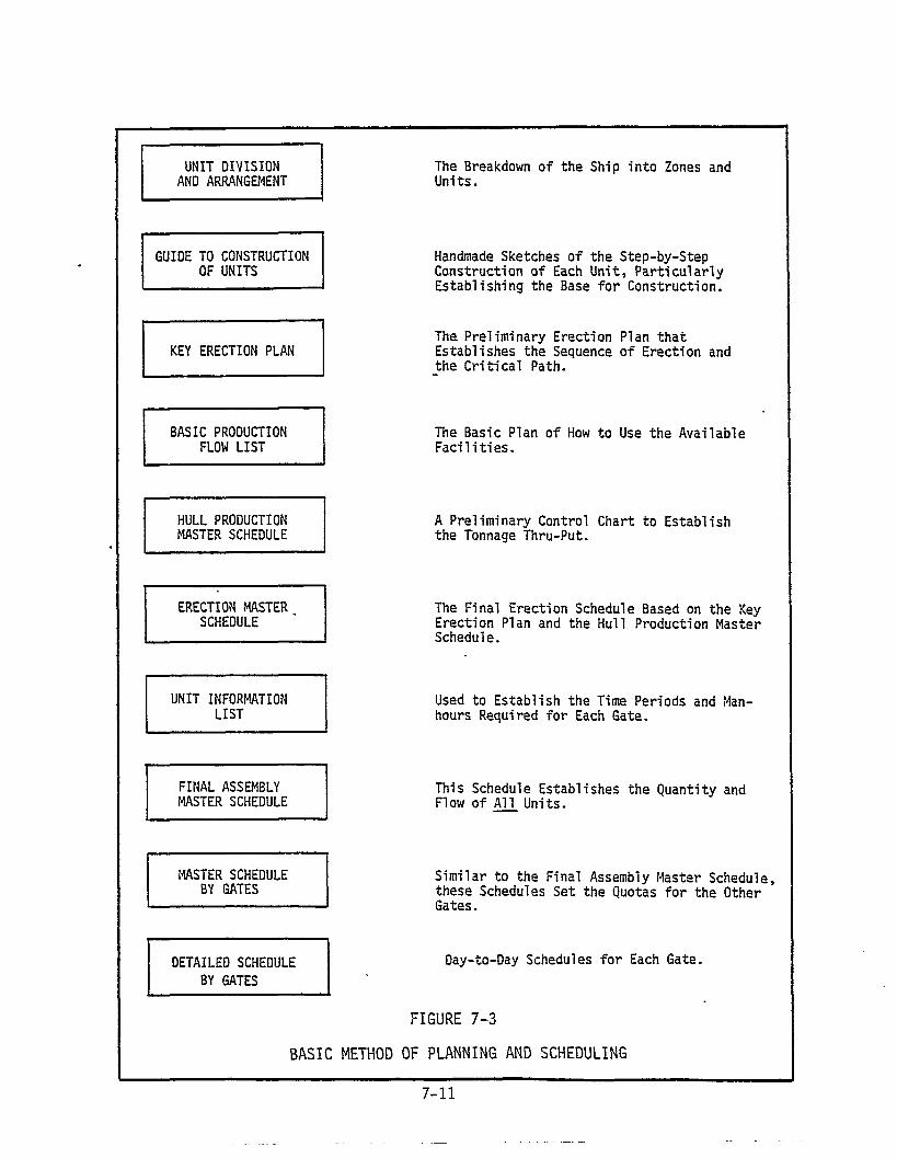


to complete the fitting and
unit can be landed. Figure
Times list.
welding necessary before the next adjoining
7-5 shows an example of a Standard Erection
7.2.3.2 Basic Production Flow List
As previously mentioned, the IHI engineers prepared a "Guide
to the Construction of Units" , which were a series of sketches showing
the assembly sequence of each unit. In the process of breaking each
unit down to components and sub-assemblies, the engineer can make basic
decisions as to what process lane can be used to fabricate the component.
Later, the engineer can also confirm the method and determine the gates
through which the component will flow. This process was used to plan
the flow of material through the new "Gate System". Considerations
for determining the proper process gates were numerous including factors
such as: crane capacities, the amount of area required, the amount of
work that would have to be processed through each gate, buffer storage
requirements, etc. When completed, this list became known as the Basic
Production Flow List. Figure 7-6 shows an example of this list.
7.2.3.3 Unit Information List
Based on the Basic Production Flow List, a Unit Information List
was compiled. This list established a time frame for the fabrication,
assembly and erection of each unit and estimated the number of workers
(in manhours) and the types of personnel required for each operation.
The preparation of this list required intensive study of the facilities
and capabilities of the LSCo. yard as revised to the new "Gate System".
Naturally, no historical data was available for the estimation of time
and manpower requirements and because of the urgent requirement for
7-13

PROCESS (1) (2) (3) (4) (5) (6) (7) (8) (9) (l0) (11) FIT FIT
TYPE OF UNITWELD BACK- WELD WELD OUT-
LIFT SET MN. JTS. INT. JTS 1ST SIDE GOUGE OP. SIDE INTS. INSP. FITTING
Double-Bottom CenterUnitsDays Required .5 .5 .5 1 .5 1 1
Double-Bottom CenterSide UnitsOays Required .5 1 1 1 .5 1 1
Bilge Units
Days Required .5 1 1 1 1 1 1 2
Stools
Days Required .5 2 1 1 1 .5 1 2
Bulkheads
Days Required .5 2 1 1 1 0 1 3
Top Side Tank Units
Days Required 1 2 2 2 1 2 3
Upper Deck Center Units
Days Required .5 1 1 2 1 1 1 2
Curved Units
Days Required 1 1.5 1.5 1 2 1 2 2
Curved Unit-to-Unit
Days Required 1 2 2 2 3 2 3 4
FIGURE 7-5
KEY ERECTION TIMES LIST
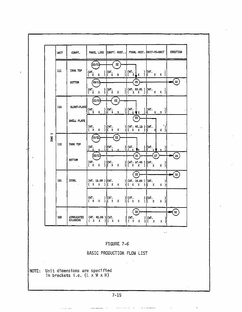

working
that it
thereon
level schedules this list was prepared with the foreknowledge
would require many revisions before the information listed
became accurate. Figure 7-7 provides an example of this list.
7.3 OUTFIT PLANNING
Outfit planning on the first of the bulk carriers began using the
IHI techniques. As in the IHI process, the ship was divided into a
series of outfitting zones and the necessary outfitting was then planned
for each zone. No attempt was made to closely tie this planning with
the engineering or purchasing effort as that was considered an advance-
ment of the planning activity that would require extensive future study
and application.
The outfitting zones selected by LSCo. planners were essentially
work zones in the IHI terminology and dealt primarily with the unit
sub-assemblies and assemblies that had been identified during the hull
b r e a k d o w n .
The planning for each work zone included the identification of
each part and piece of outfitting material (with the exception of
electrical:
components
equivalent
identified
that would be required for each assembly unit. These
were listed on a Material Information List which is the
of the IHI Material List for Fitting (MLF). The list
not only each component, but also the point in the building
cycle of the assembly unit at which the component was to be installed,
by whom (i.e. craft), and the estimated manhours required. Figure
7-8 presents an example of a Material Information List.
Pipe fabrication was handled in a manner similar to that of
IHI. Pipe components were listed on a separate Pipe Material List
7-16


together with all relevant information as to zone number, schedule
requirements, and whether the pipe was to be fabricated or purchased.
Information from this list was then transferred to pipe fabrication
schedules for use by the Pipe Shop and Material Control personnel.
The two material lists of fitting components and pipe were oriented
by assembly unit and thus could be scheduled in accordance with the
fabrication and assembly of steel during the unit build-up.
The objective of this planning was, as at IHI, to accomplish as
much pre-outfitting as possible on the slabs during the build-up of
the steel assembly units and thereby reduce the extensive on-board
outfitting required by traditional methods.
The many changes occurring in both the planning and scheduling
system and in the production system itself with the conversion to the
Gate System minimized the effectiveness of this outfit planning on
the first vessel. Too often pre-outfitting was prevented by the
exigencies of material flow and excessive manhour requirements in the
steel assembly process. However, the major assembly units, such as
engine room flats, were outfitted on slab areas and were able to be
landed in completed module form aboard the erected ship. This pre-
outfitting planning is being more fully implemented on each succeeding
ship.
During the initial implementation of the outfit planning it became
apparent that the IHI concept of palletization was essential to the
successful adaptation of the outfitting activity. Several studies
were conducted by both IHI consultants and LSCo. Industrial Engineers
to ascertain the minimal requirements for getting a palletization
7-19

system started to support the collection of pipe and other outfitting
components. Once completed, recommendations from these studies were
implemented and several different configurations of outfitting pallets
were put into use. The concept of palletization includes not only the
accumulation of material onto pallets which will be routed to outfitting
locations on a
concerned with
This system of
ting activity;
specific schedule, but also the requisite information
schedule, personnel and installation sketches or drawings.
palletization is being followed by LSCo. in its outfit-
however, not in the precise form utilized by IHI. As
the system becomes more perfected, it is expected that the LSCo. system
will more closely approximate that of IHI.
7.4 SCHEDULES
A descending hierarchy of schedules similar to those used by IHI
was developed to support the Gate System. These schedules derive
from the
shipyard
Assembly
Key Erection Plan and basically evolve from the top-level
schedule, to a Ship Erection Master Schedule, to a Final
Master Schedule, to several subordinate master schedules by
gate to detailed schedules for each gate.
provide examples of each type of schedule
the Gate System.
Figures 7-9 through 7-14
presently used to support
7.5 MANPOWER PLANNING AND PERFORMANCE MEASUREMENT
The planning and implementation of the Gate System provided an
excellent opportunity to establish manpower levels and manhour re-
quirements for each operation within the yard. These levels and man-
hours were estimated initially by Production Control personnel and
actual manhours are presently being monitored for comparison with
these estimates. Once the gates are fully functioning, these estimates,
7-20
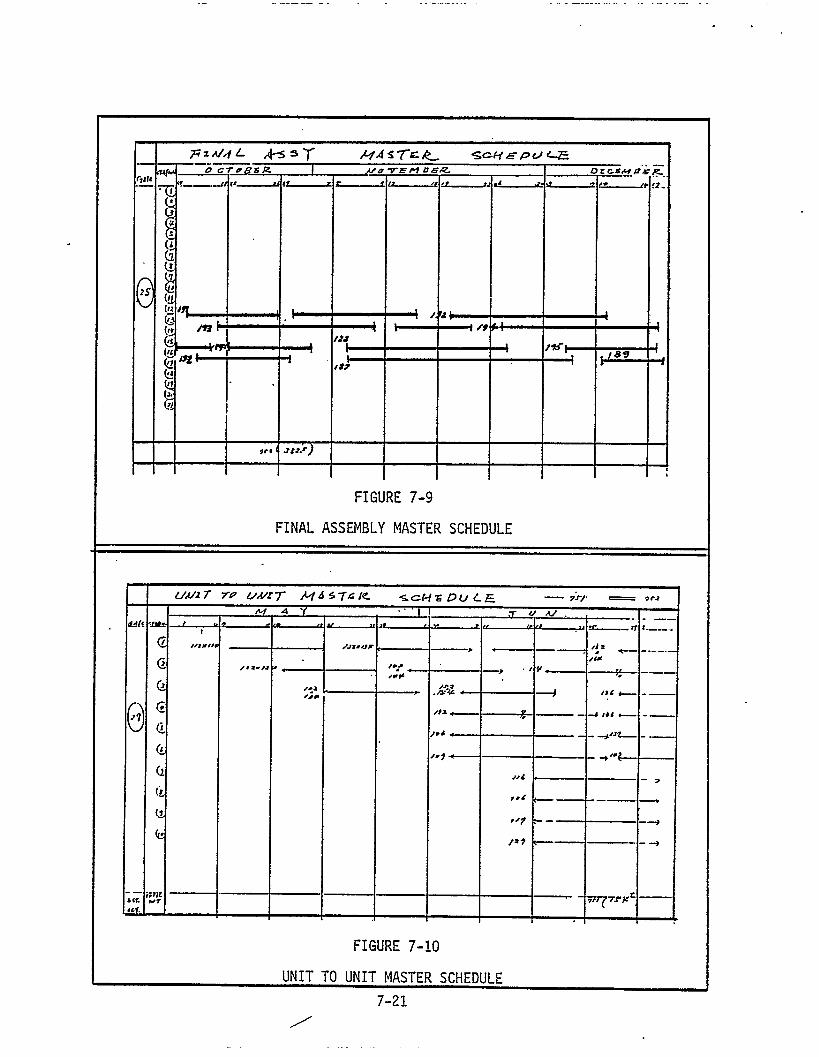


as adjusted to conform with actual experience, will become the standards
for each process gate.
Performance measurement for gates already functioning is also
being developed, initially on the basis of weight throughput. Studies
of weld metal deposit per hour are also being performed and will be
incorporated into the performance measurement activity in the future.
7.6 CURRENT LIVINGSTON APPLICATION
With the adaptation of the "Gate System" Livingston is fully com-
mitted to the application of the IHI production planning and control
techniques. These techniques have necessarily been modified to fit
the facilities, capabilities and personnel organization of Levingston.
Many of the peripheral aspects of the system, such as Accuracy Control,
decentralized planning and production control, the decentralized or-
ganization of work groups and staff groups, and total communication
of planning and scheduling information to the work positions, have
not yet been addressed in their fullest degree for application.
The re-orientation of an entire and traditional ship production
system is a lengthy undertaking. A great deal of personnel training,
as well as reorganization of facilities and material flow is involved
and must be carefully structured in a step-by-step manner over a
prolonged period.
Currently, Livingston has adopted only a portion of the planning
methodology used by IHI. Table T7-1 shows the planning techniques
presently utilized by LSCo. versus those of IHI. The
in the table that has not been adopted by LSCo. is of
plished in one form or another, but is generally less
planning shown
course, accom-
formal and
7-24


less discretely identified than that of IHI. For example, many of
the Working Instruction Plans shown as not adopted by LSCo. are pre-
pared as part of the engineering or Industrial Engineering activities
of LSCo. It is the planning concerned primarily with the fabrication,
sub-assembly, assembly and erection of steel and the pre-outfitting
and outfitting of the assembly units and the erected hull that has
been emphasized by LSCo. in the Technology Transfer Program and until
this planning and control methodology has been mastered and fully
implemented, the remaining types of planning will be deferred.
The basic production system, the material handling and control
system, scheduling, manpower planning and performance measurement
systems have all been adapted to the LSCo. yard and although the
implementation of these systems is far from complete, the basic
decisions have been made and the eventual goals established for the
complete reorganization of the LSCo. shipbuilding process. Figure
7-15 presents a diagram of the current Livingston planning, scheduling
and manning control system as described in the preceding paragraphs.
7-26
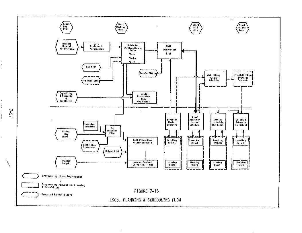

SECTION 8
APPLICATION TO U.S. SHIPBUILDING
8.1 GENERAL
The application of the IHI Planning and Production Control system
to typical U.S. shipyards is entirely practicable and desirable. The
institution of this system, however, requires major modification not
only to the planning and scheduling practices of the typical U.S. yard
but also to the production system itself.
As explained previously, the heart of the Japanese system is the
organization of the production flow through "Process Lanes". These
lanes are the essential ingredient to the establishment of the planning
and production control methods utilized by IHI. This may entail some
radical changes in yards which have not been structured around an
"interim product" or "module" type of ship construction.
Although module construction methods have been practiced by many
U.S. yards, the full potential of these methods, as demonstrated by
the Japanese, have seldom been realized in this country. Much of
the reason for this is attributable to the traditional practices and
reticence to change established production systems. Any re-organization
of the physical facilites of many yards is an expensive and time-
consuming undertaking. In the midst of ship construction this under-
taking may severely penalize the work in process. It is therefore
understandable why most yards are reticent to experiment with different
production systems even though these systems are quite obviously more
efficient and contribute to increased productivity.
8-1

The institution of the IHI system requires a thoroughly developed
plan which must be executed at the beginning of each new contract.
Since the majority of planning for production needs to be accomplished
prior to the start of fabrication, this planning should be incorporated
into the design effort and, in fact, be a part of the design development.
Naturally, in order for this planning to be meaningful, the production
system, both hull construction and outfitting, must be thoroughly
developed and in place to support a rapid and optimized production
schedule once fabrication has begun.
Several major obstacles present themselves in the institution of
this type of planning and control system. The most formidable, of
course, is the realignment of the production system into a "Process
Lanes" type of organization. The second is the development of the
planning and production control system organized around the new pro-
duction structure. Additionally, restraining of personnel, material
flow/handling/control, pre-outfitting, and the application of accuracy
control and quality control methods to the new system must all be in-
vestigated to ensure that all aspects are integrated to form a precise
composite that does indeed benefit and not degrade production rates.
Each shipyard has its peculiarities of location; geographical
arrangement; facilities layout; physical plant complement of machinery,
equipment, and transportation; and those related to the mix, skill
levels and other characteristics
each yard will necessarily adopt
in a somewhat different manner.
IHI will have direct application
of its workforce. For these reasons
the Japanese concepts of production
Not all of the methods utilized by
in each yard; however, the general
methodology is applicable without exception.
8-2
8.2 HULL CONSTRUCTION
The practices of IHI regarding the division of the hull into unit
assemblies (or interim products) is basic to the planning system and,
of course, to the production system. This single aspect of the IHI
methodology carries throughout all of the planning, scheduling, man-
power planning, and performance measurement practices of the IHI yards.
The production system is organized to produce the components necessary
to build the sub-assemblies and the assemblies which ultimately will
be erected in the building basin. The flows developed for this fabrica-
tion and build-up are extremely logical and practical
effort applied toward perfecting each process step to
efficiency and accuracy of each product.
with determined
improve both
After the breakdown of the ship into the assembly (or erection)
units, the process becomes one of further defining the parts, pieces
and processes for each assembly unit. A separate (but integral) part
of this planning process involves the identification and scheduling
of outfitting components to be integrated into the evolving hull units.
Once accomplished, this planning becomes the baseline for the
planning of manpower at each process stage and sub-stage and, in an
iterative process involving the application of manpower to schedules,
the hierarchy of schedules is developed to provide the optimum loading
of personnel into the shortest possible schedule.
This type of hull planning and construction is contingent on a
thoroughly designed and established production system which to a large
extent is predictable in its performance. IHI developed its production
system over a period of 15 to 20 years and continually made modifications
8-3
to improve the system's performance. Even though a thoroughly designed
model of the system exists (in the Japanese yards), U.S. yards seeking
to institute such a system will have a difficult period of development
before achieving anything close to the productivity rates of the Japanese.
The realignment of any production system requires a total commitment
and consistent dedication to effect the change and, even then, in an
industry as complex as ship construction, the
quickly.
Unlike many of the other systems of IHI,
change will not be effected
the Planning and Produc-
tion Control System cannot be fragmented either for selective institu-
tion of a few parts of the system or for gradual implementation over
a prolonged period of time. Because the planning system is intimately
tied to the production system, each must reflect the other and no
appreciable effect will be felt
extent that the majority of the
Certain planning and scheduling
have some beneficial effects on
until both are developed to such an
total system is effectively operating.
techniques may be instituted and may
production; however, the great in-
creases in productivity reflected in the Japanese system are not pos-
sible without the adoption of the total planning and production system.
8.3 OUTFITTING
Pre-outfitting is another area that has been widely discussed as
a means to greatly reduce ship construction costs. Many U.S. yards
currently employ some pre-outfitting to reduce the on-board outfitting
of difficult functional systems. However, the IHI pre-outfitting
practices are tied directly to the production of the hull assembly
units and to the production system which produces them. The study
8-4
and application of the principles of pre-outfitting utilized by IHI
must necessarily correspond to the principles of hull construction
used by those yards. Otherwise, the advantages gained by the use of
the IHI pre-outfitting methods will be marginal and may even have
deleterious effects on production schedules.
Pre-outfitting, of course, can be instituted in U.S. yards a
number of ways. Certainly, the IHI methods are not the only alterna-
tive in this important area. Any method of pre-outfitting which serves
to diminish the time spent in erection or on-board outfitting will
contribute to reduced costs; however, pre-outfitting itself is not
a panacea for poor production efficiency. Rather, it is simply one
of the many aspects of production which must be integrated in a total
planning and production system. The attempt to institute the IHI
pre-outfitting methods in a traditional ship construction system (i.e.
a ship assembled and erected on the ways) simply would not work, and,
even in a production system only slightly modified from the traditional
approach, these methods would be extremely difficult and generally in-
effective.
Livingston’s study of the IHI system has derived one over-riding
axiom for the application of IHI practices, that is: the IHI ship con-
struction system is a well developed and highly integrated whole,
pieces of which can be adopted for use in U.S. yards and can be
effective, but only through the adoption of the total system can any
great increase in productivity be effected. This applies especially
to the planning and production control system. Only through the
adoption of the IHI production system does the direct application of
8-5

the IHI planning and control system have meaning and, similarly, only
through the adoption of the production system does the IHI pre-outfit-
ting methodology have significant benefit. Each piece of the planning
and production system is dependent upon every other piece. One piece
cannot stand alone.
8.4 CONCLUSION
The IHI Planning and Production Control System is a comprehensive
and effective system in the IHI shipyards, but because of its total
orientation toward the production system, methods, processes and tech-
niques of the IHI yards, its application to U.S. yards is dependent
on the willingness of U.S. yards to change their production methodology.
There is little doubt that should a U.S. yard successfully replicate
the IHI planning and production system that such a system would have
a significant effect on productivity although, because of the cultural
differences between the two countries, U.S. yards may never achieve
the productivity levels experienced by Japan. Many more aspects of
productivity, besides those of planning and the production system,
will influence the ultimate productivity equation and, although this
area of production is by far the most significant in terms of tech-
nology that can be adopted by the U.S., it is entirely possible that
the areas of non-technological application (such as personnel relations)
can produce an influence of equal proportion. In any case, U.S. yards
cannot help but derive benefit from the study of this technological
area.
Recommended