PON Technology – A Shift in Building Network Infrastructure
Bob Matthews Technical Manager
CommScope Canada
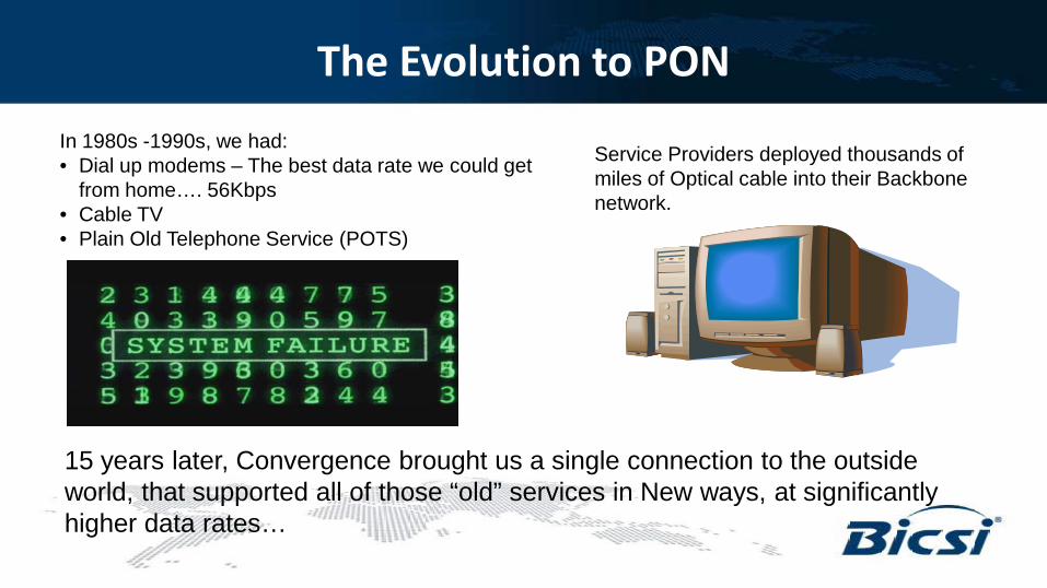
The Evolution to PON In 1980s -1990s, we had: • Dial up modems – The best data rate we could get
from home…. 56Kbps • Cable TV • Plain Old Telephone Service (POTS)
15 years later, Convergence brought us a single connection to the outside world, that supported all of those “old” services in New ways, at significantly higher data rates…
Service Providers deployed thousands of miles of Optical cable into their Backbone network.
So, what is PON (or POL)?
• A passive optical network (PON) is a telecommunications network that uses point to multipoint fiber to the premises in which unpowered optical splitters are used to enable a single optical fiber to serve multiple premises. A PON consists of an Optical Line Terminal (OLT) at the service provider's central office and a number of Optical Network Units (ONUs) near the end users. A PON reduces the amount of fiber and central office equipment required compared with point to point architectures. A passive optical network is a form of fiber-optic access network.
credit – Wikipedia, the free encyclopedia
Definition:
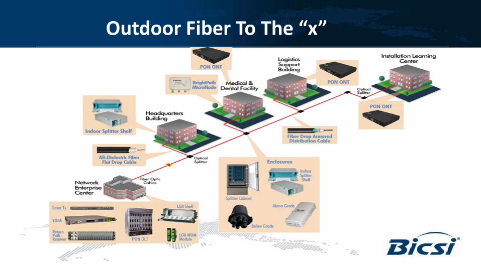
Outdoor Fiber To The “x”
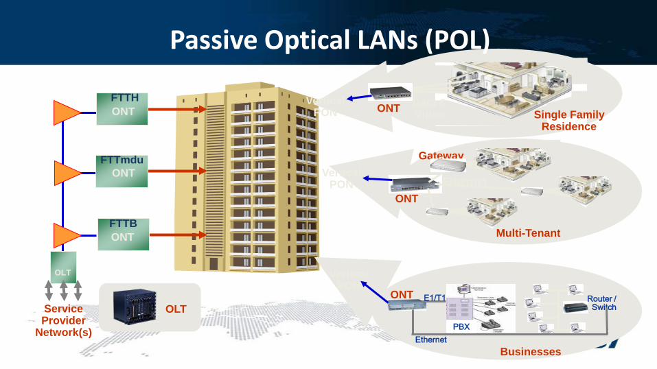
Passive Optical LANs (POL)
OLT
Service Provider
Network(s)
FTTH
FTTmdu
FTTB
ONT
ONT
ONT
Data & Video ONT Single Family
Residence
Vertical PON
Vertical PON
Vertical PON
Gateway
Multi-Tenant
Ethernet ONT
OLT
Businesses
Router / Switch
PBX
E1/T1
Ethernet
ONT
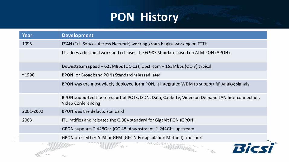
PON History Year Development 1995 FSAN (Full Service Access Network) working group begins working on FTTH
ITU does additional work and releases the G.983 Standard based on ATM PON (APON).
Downstream speed – 622MBps (OC-12); Upstream – 155Mbps (OC-3) typical
~1998 BPON (or Broadband PON) Standard released later
BPON was the most widely deployed form PON, it integrated WDM to support RF Analog signals
BPON supported the transport of POTS, ISDN, Data, Cable TV, Video on Demand LAN Interconnection, Video Conferencing
2001-2002 BPON was the defacto standard
2003 ITU ratifies and releases the G.984 standard for Gigabit PON (GPON)
GPON supports 2.448Gbs (OC-48) downstream, 1.244Gbs upstream
GPON uses either ATM or GEM (GPON Encapsulation Method) transport
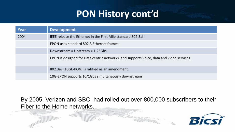
PON History cont’d Year Development 2004 IEEE release the Ethernet in the First Mile standard 802.3ah
EPON uses standard 802.3 Ethernet frames
Downstream = Upstream = 1.25Gbs
EPON is designed for Data centric networks, and supports Voice, data and video services.
802.3av (10GE-PON) is ratified as an amendment.
10G-EPON supports 10/1Gbs simultaneously downstream
By 2005, Verizon and SBC had rolled out over 800,000 subscribers to their Fiber to the Home networks.
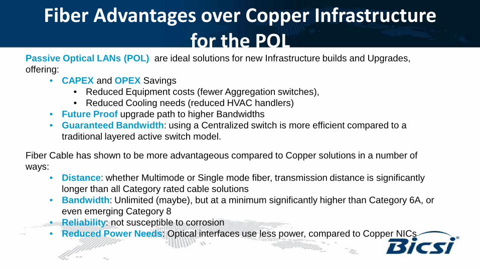
Fiber Advantages over Copper Infrastructure for the POL
Fiber Cable has shown to be more advantageous compared to Copper solutions in a number of ways:
• Distance: whether Multimode or Single mode fiber, transmission distance is significantly longer than all Category rated cable solutions
• Bandwidth: Unlimited (maybe), but at a minimum significantly higher than Category 6A, or even emerging Category 8
• Reliability: not susceptible to corrosion • Reduced Power Needs: Optical interfaces use less power, compared to Copper NICs
Passive Optical LANs (POL) are ideal solutions for new Infrastructure builds and Upgrades, offering:
• CAPEX and OPEX Savings • Reduced Equipment costs (fewer Aggregation switches), • Reduced Cooling needs (reduced HVAC handlers)
• Future Proof upgrade path to higher Bandwidths • Guaranteed Bandwidth: using a Centralized switch is more efficient compared to a
traditional layered active switch model.
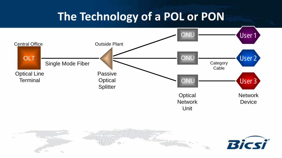
The Technology of a POL or PON ONT
ONT
ONT
ONU
ONU
ONU
OLT
User 1
User 2
User 3 Optical Line
Terminal Passive Optical Splitter
Optical Network
Unit
Single Mode Fiber
Network Device
Category Cable
Central Office Outside Plant
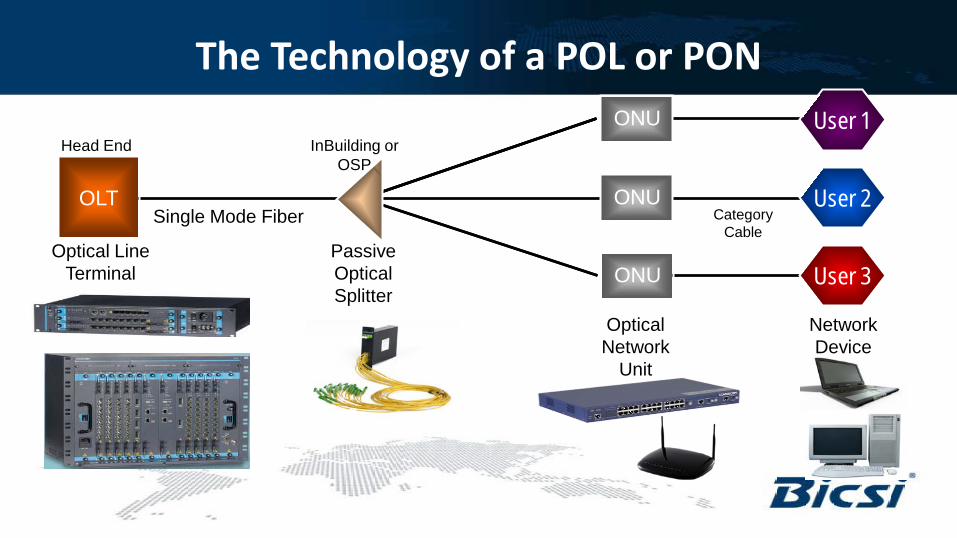
The Technology of a POL or PON ONT
ONT
ONT
ONU
ONU
ONU
OLT
User 1
User 2
User 3 Optical Line
Terminal Passive Optical Splitter
Optical Network
Unit
Single Mode Fiber
Network Device
Category Cable
Head End InBuilding or OSP
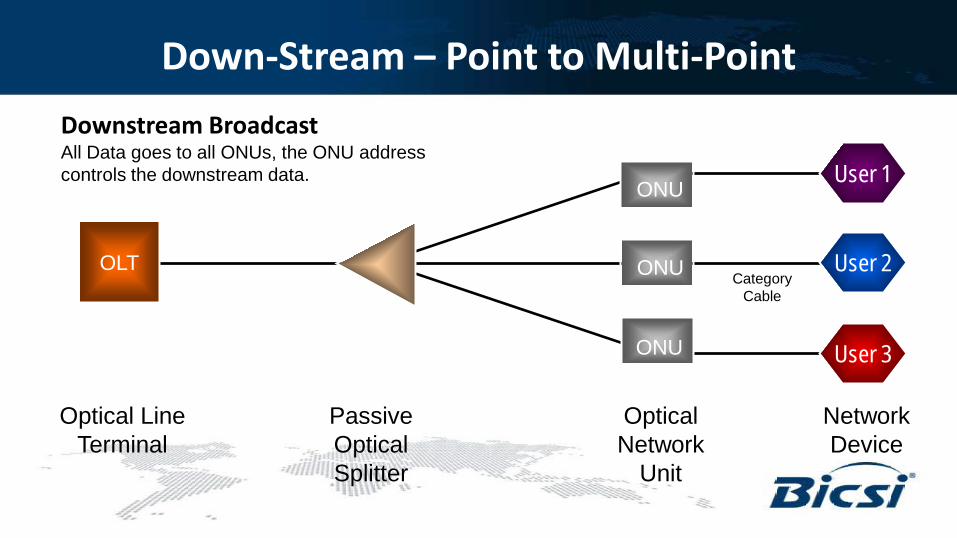
Down-Stream – Point to Multi-Point
Category Cable
Downstream Broadcast All Data goes to all ONUs, the ONU address controls the downstream data.
Optical Line Terminal
Passive Optical Splitter
Optical Network
Unit
Network Device
OLT
ONU
ONU
ONU
User 1
User 2
User 3
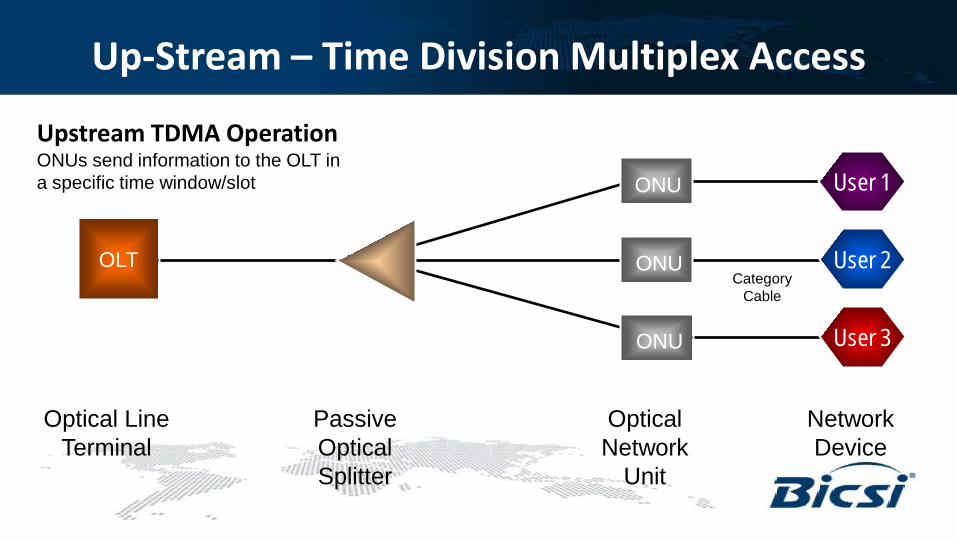
Up-Stream – Time Division Multiplex Access
Upstream TDMA Operation ONUs send information to the OLT in a specific time window/slot
Optical Line Terminal
Passive Optical Splitter
Optical Network
Unit
Network Device
User 1
User 2
User 3
Category Cable
ONU
ONU
ONU
OLT
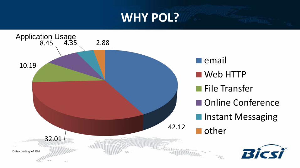
WHY POL?
42.12
32.01
10.19
8.45 4.35 2.88
email Web HTTP File Transfer Online Conference Instant Messaging other
Application Usage
Data courtesy of IBM
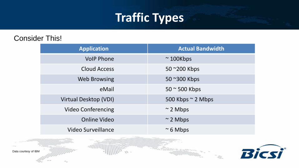
Traffic Types Consider This!
Application Actual Bandwidth
VoIP Phone ~ 100Kbps
Cloud Access 50 ~200 Kbps
Web Browsing 50 ~300 Kbps
eMail 50 ~ 500 Kbps
Virtual Desktop (VDI) 500 Kbps ~ 2 Mbps
Video Conferencing ~ 2 Mbps
Online Video ~ 2 Mbps
Video Surveillance ~ 6 Mbps
Data courtesy of IBM
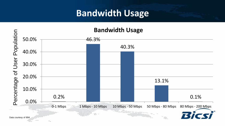
Bandwidth Usage
0.2%
46.3% 40.3%
13.1%
0.1% 0.0%
10.0%
20.0%
30.0%
40.0%
50.0%
0-1 Mbps 1 Mbps - 10 Mbps 10 Mbps - 50 Mbps 50 Mbps - 80 Mbps 80 Mbps - 200 Mbps
Bandwidth Usage
Per
cent
age
of U
ser P
opul
atio
n
Data courtesy of IBM
Observations
• ~ 74% of traffic was Email and Web Surfing • ~ 95% of the Users used less than 80 Mbps in
total Bandwidth (86% used less than 50Mbps) • That most applications do not require the Bandwidth
we think • Most traffic was passed through the Core Router, very
little peer to peer traffic • Enterprise traffic is Hub and Spoke based, generally
applications reside in a Central Data Center • HTTP traffic increases as Cloud services increase • The Usage patterns which give rise to decentralized computing and LANs are shifting
back to a centralized model with a different network architecture
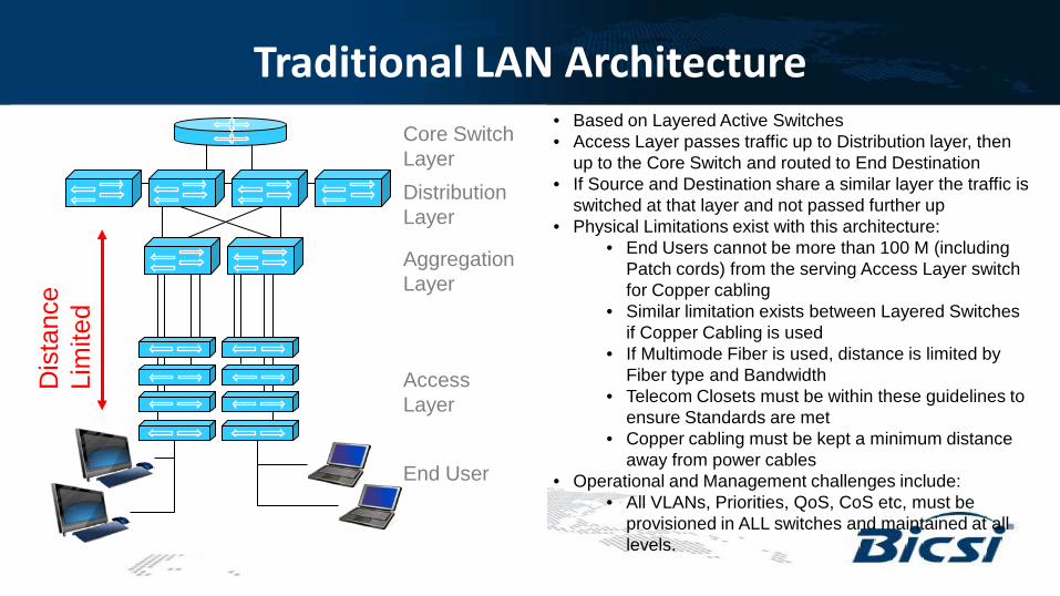
Traditional LAN Architecture
End User
Access Layer
Aggregation Layer
Distribution Layer
Core Switch Layer
Dis
tanc
e Li
mite
d • Based on Layered Active Switches • Access Layer passes traffic up to Distribution layer, then
up to the Core Switch and routed to End Destination • If Source and Destination share a similar layer the traffic is
switched at that layer and not passed further up • Physical Limitations exist with this architecture:
• End Users cannot be more than 100 M (including Patch cords) from the serving Access Layer switch for Copper cabling
• Similar limitation exists between Layered Switches if Copper Cabling is used
• If Multimode Fiber is used, distance is limited by Fiber type and Bandwidth
• Telecom Closets must be within these guidelines to ensure Standards are met
• Copper cabling must be kept a minimum distance away from power cables
• Operational and Management challenges include: • All VLANs, Priorities, QoS, CoS etc, must be
provisioned in ALL switches and maintained at all levels.
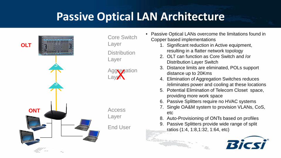
Passive Optical LAN Architecture • Passive Optical LANs overcome the limitations found in
Copper based implementations 1. Significant reduction in Active equipment,
resulting in a flatter network topology 2. OLT can function as Core Switch and /or
Distribution Layer Switch 3. Distance limits are eliminated, POLs support
distance up to 20Kms 4. Elimination of Aggregation Switches reduces
/eliminates power and cooling at these locations 5. Potential Elimination of Telecom Closet space,
providing more work space 6. Passive Splitters require no HVAC systems 7. Single OA&M system to provision VLANs, CoS,
etc 8. Auto-Provisioning of ONTs based on profiles 9. Passive Splitters provide wide range of split
ratios (1:4, 1:8,1:32, 1:64, etc) End User
Access Layer
Aggregation Layer
Distribution Layer
Core Switch Layer OLT
S
S
ONT
X
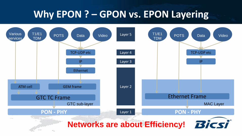
Why EPON ? – GPON vs. EPON Layering
Layer 1
Layer 2
Layer 3
Layer 4
Layer 5
PON - PHY
Ethernet
IP
TCP-UDP etc
GTC TC Frame GTC sub-layer
ATM cell GEM frame
Various services
T1/E1 TDM
POTS Data Video
PON - PHY
IP
TCP-UDP etc
Ethernet Frame MAC Layer
T1/E1 TDM
POTS Data Video
Networks are about Efficiency!
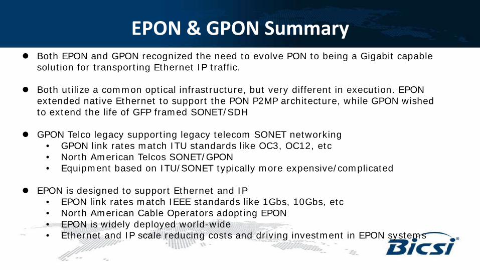
Both EPON and GPON recognized the need to evolve PON to being a Gigabit capable solution for transporting Ethernet IP traffic.
Both utilize a common optical infrastructure, but very different in execution. EPON extended native Ethernet to support the PON P2MP architecture, while GPON wished to extend the life of GFP framed SONET/SDH
GPON Telco legacy supporting legacy telecom SONET networking • GPON link rates match ITU standards like OC3, OC12, etc • North American Telcos SONET/GPON • Equipment based on ITU/SONET typically more expensive/complicated
EPON is designed to support Ethernet and IP
• EPON link rates match IEEE standards like 1Gbs, 10Gbs, etc • North American Cable Operators adopting EPON • EPON is widely deployed world-wide • Ethernet and IP scale reducing costs and driving investment in EPON systems
EPON & GPON Summary
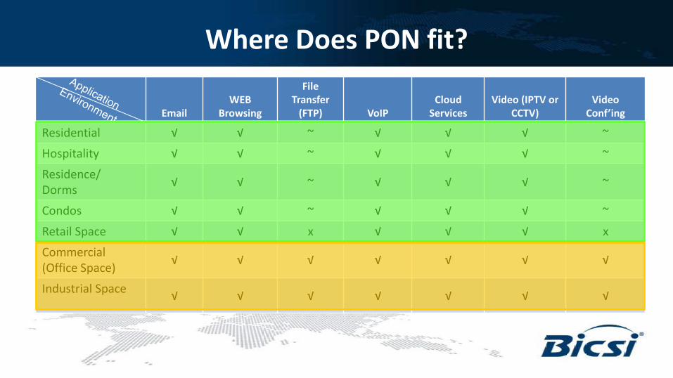
Where Does PON fit?
Email WEB
Browsing
File Transfer
(FTP) VoIP Cloud
Services Video (IPTV or
CCTV) Video
Conf’ing
Residential √ √ ~ √ √ √ ~
Hospitality √ √ ~ √ √ √ ~
Residence/ Dorms √ √ ~ √ √ √ ~
Condos √ √ ~ √ √ √ ~
Retail Space √ √ x √ √ √ x
Commercial (Office Space) √ √ √ √ √ √ √
Industrial Space √ √ √ √ √ √ √
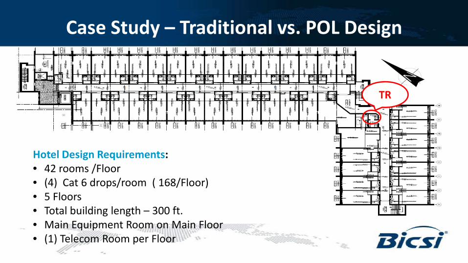
Case Study – Traditional vs. POL Design
Hotel Design Requirements: • 42 rooms /Floor • (4) Cat 6 drops/room ( 168/Floor) • 5 Floors • Total building length – 300 ft. • Main Equipment Room on Main Floor • (1) Telecom Room per Floor
TR
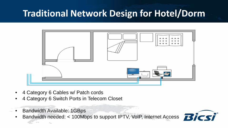
Traditional Network Design for Hotel/Dorm
• 4 Category 6 Cables w/ Patch cords • 4 Category 6 Switch Ports in Telecom Closet
• Bandwidth Available: 1GBps • Bandwidth needed: < 100Mbps to support IPTV, VoIP, Internet Access
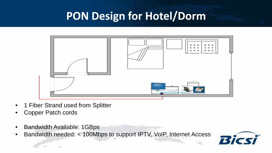
PON Design for Hotel/Dorm
• 1 Fiber Strand used from Splitter • Copper Patch cords
• Bandwidth Available: 1GBps • Bandwidth needed: < 100Mbps to support IPTV, VoIP, Internet Access
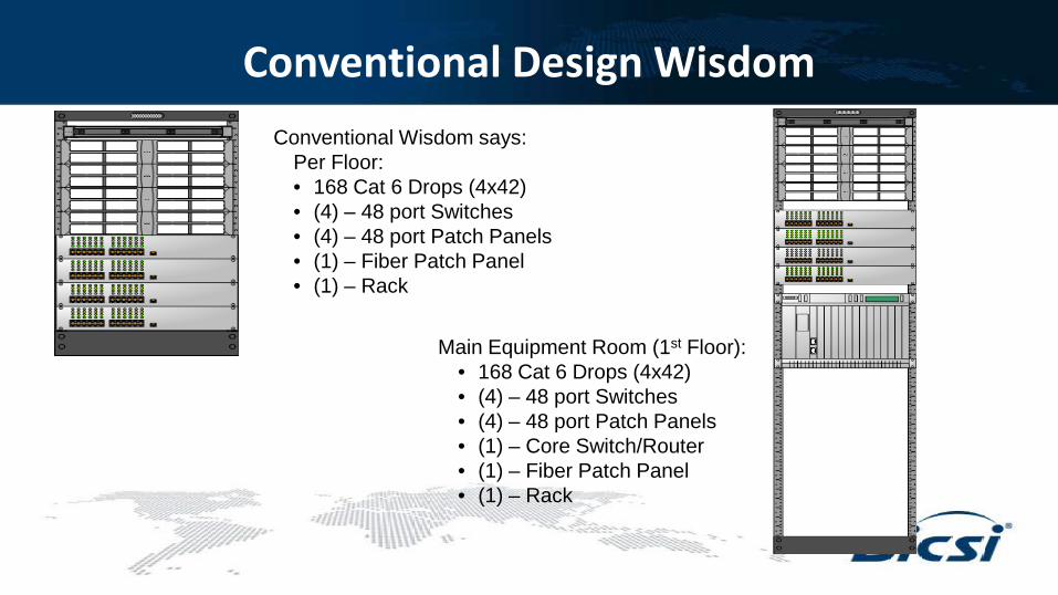
Conventional Design Wisdom Conventional Wisdom says:
Per Floor: • 168 Cat 6 Drops (4x42) • (4) – 48 port Switches • (4) – 48 port Patch Panels • (1) – Fiber Patch Panel • (1) – Rack
Main Equipment Room (1st Floor): • 168 Cat 6 Drops (4x42) • (4) – 48 port Switches • (4) – 48 port Patch Panels • (1) – Core Switch/Router • (1) – Fiber Patch Panel • (1) – Rack
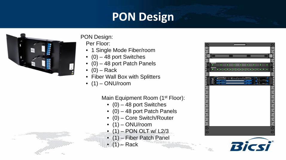
PON Design PON Design:
Per Floor: • 1 Single Mode Fiber/room • (0) – 48 port Switches • (0) – 48 port Patch Panels • (0) – Rack • Fiber Wall Box with Splitters • (1) – ONU/room
Main Equipment Room (1st Floor): • (0) – 48 port Switches • (0) – 48 port Patch Panels • (0) – Core Switch/Router • (1) – ONU/room • (1) – PON OLT w/ L2/3 • (1) – Fiber Patch Panel • (1) – Rack
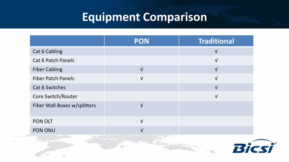
Equipment Comparison
PON Traditional Cat 6 Cabling √
Cat 6 Patch Panels √
Fiber Cabling √ √
Fiber Patch Panels √ √
Cat 6 Switches √
Core Switch/Router √
Fiber Wall Boxes w/splitters √
PON OLT √
PON ONU √
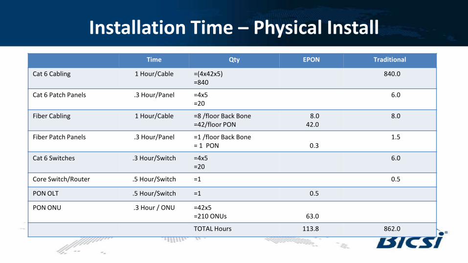
Installation Time – Physical Install Time Qty EPON Traditional
Cat 6 Cabling 1 Hour/Cable =(4x42x5) =840
840.0
Cat 6 Patch Panels .3 Hour/Panel =4x5 =20
6.0
Fiber Cabling 1 Hour/Cable =8 /floor Back Bone =42/floor PON
8.0 42.0
8.0
Fiber Patch Panels .3 Hour/Panel =1 /floor Back Bone = 1 PON
0.3
1.5
Cat 6 Switches .3 Hour/Switch =4x5 =20
6.0
Core Switch/Router .5 Hour/Switch =1 0.5
PON OLT .5 Hour/Switch =1 0.5
PON ONU .3 Hour / ONU =42x5 =210 ONUs
63.0
TOTAL Hours 113.8 862.0
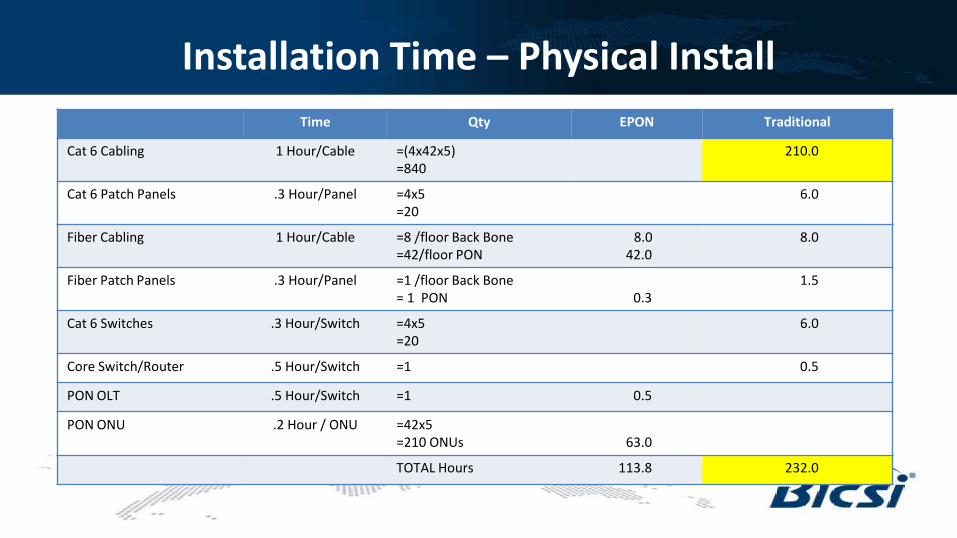
Installation Time – Physical Install Time Qty EPON Traditional
Cat 6 Cabling 1 Hour/Cable =(4x42x5) =840
210.0
Cat 6 Patch Panels .3 Hour/Panel =4x5 =20
6.0
Fiber Cabling 1 Hour/Cable =8 /floor Back Bone =42/floor PON
8.0 42.0
8.0
Fiber Patch Panels .3 Hour/Panel =1 /floor Back Bone = 1 PON
0.3
1.5
Cat 6 Switches .3 Hour/Switch =4x5 =20
6.0
Core Switch/Router .5 Hour/Switch =1 0.5
PON OLT .5 Hour/Switch =1 0.5
PON ONU .2 Hour / ONU =42x5 =210 ONUs
63.0
TOTAL Hours 113.8 232.0
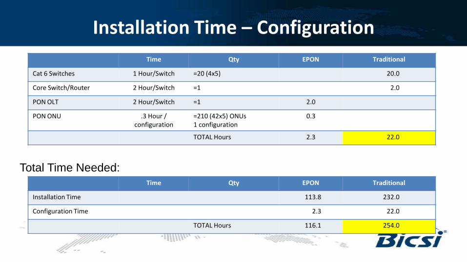
Installation Time – Configuration Time Qty EPON Traditional
Cat 6 Switches 1 Hour/Switch =20 (4x5) 20.0
Core Switch/Router 2 Hour/Switch =1 2.0
PON OLT 2 Hour/Switch =1 2.0
PON ONU .3 Hour / configuration
=210 (42x5) ONUs 1 configuration
0.3
TOTAL Hours 2.3 22.0
Time Qty EPON Traditional
Installation Time 113.8 232.0
Configuration Time 2.3 22.0
TOTAL Hours 116.1 254.0
Total Time Needed:
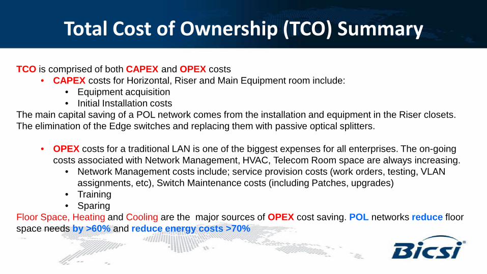
Total Cost of Ownership (TCO) Summary
TCO is comprised of both CAPEX and OPEX costs • CAPEX costs for Horizontal, Riser and Main Equipment room include:
• Equipment acquisition • Initial Installation costs
The main capital saving of a POL network comes from the installation and equipment in the Riser closets. The elimination of the Edge switches and replacing them with passive optical splitters.
• OPEX costs for a traditional LAN is one of the biggest expenses for all enterprises. The on-going
costs associated with Network Management, HVAC, Telecom Room space are always increasing. • Network Management costs include; service provision costs (work orders, testing, VLAN
assignments, etc), Switch Maintenance costs (including Patches, upgrades) • Training • Sparing
Floor Space, Heating and Cooling are the major sources of OPEX cost saving. POL networks reduce floor space needs by >60% and reduce energy costs >70%
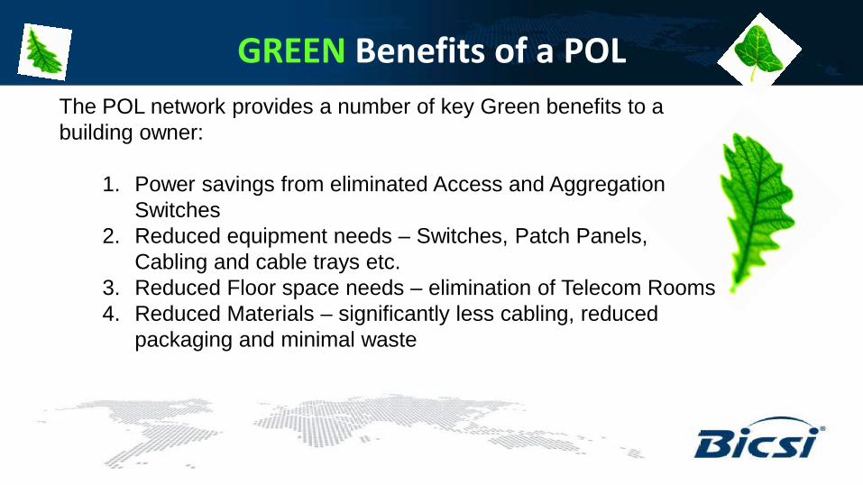
GREEN Benefits of a POL The POL network provides a number of key Green benefits to a building owner:
1. Power savings from eliminated Access and Aggregation Switches
2. Reduced equipment needs – Switches, Patch Panels, Cabling and cable trays etc.
3. Reduced Floor space needs – elimination of Telecom Rooms 4. Reduced Materials – significantly less cabling, reduced
packaging and minimal waste
Traditional networks vs. POL Summary Passive Optical LAN technology supports all of the requirements of today’s enterprise network with a much lower cost than traditional LAN designs. It is a GREEN technology, which seamlessly enables smart buildings. Finally, it supports an easy migration to higher data rates (10G) when needed.
Networks are about Efficiency! REMEMBER:
Thank You
Bob Matthews Technical Manager CommScope Canada Booth 500
Recommended