Precision-Timed (PRET) Machines
Stephen A. Edwards Columbia University Sungjun Kim Columbia University Edward A. Lee UC Berkeley Ben Lickly UC Berkeley Isaac Liu UC Berkeley Hiren D. Patel University of Waterloo Jan Reineke <speaker> Saarland University UC Berkeley
Designing Next-Generation Real-Time Streaming Systems Tutorial at HIPEAC 2013
Reineke et al., Saarland 2
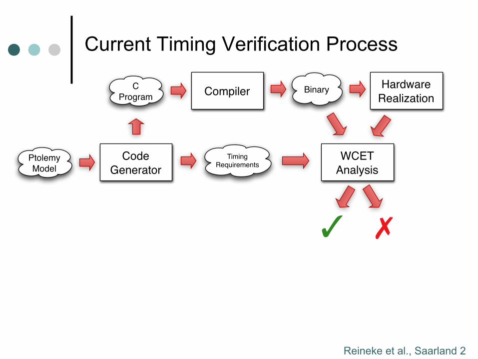
C
ProgramBinary
Hardware
RealizationCompiler
WCET
Analysis
✓ ✗
Ptolemy
Model
Code
Generator
Timing Requirements
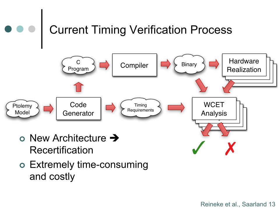
Current Timing Verification Process
Reineke et al., Saarland 3
WCET
Analysis
WCET
Analysis
WCET
Analysis
ArchitectureArchitecture
ArchitectureHardware
Realization
WCET
Analysis
C
ProgramBinaryCompiler
✓ ✗
Ptolemy
Model
Code
Generator
Timing Requirements
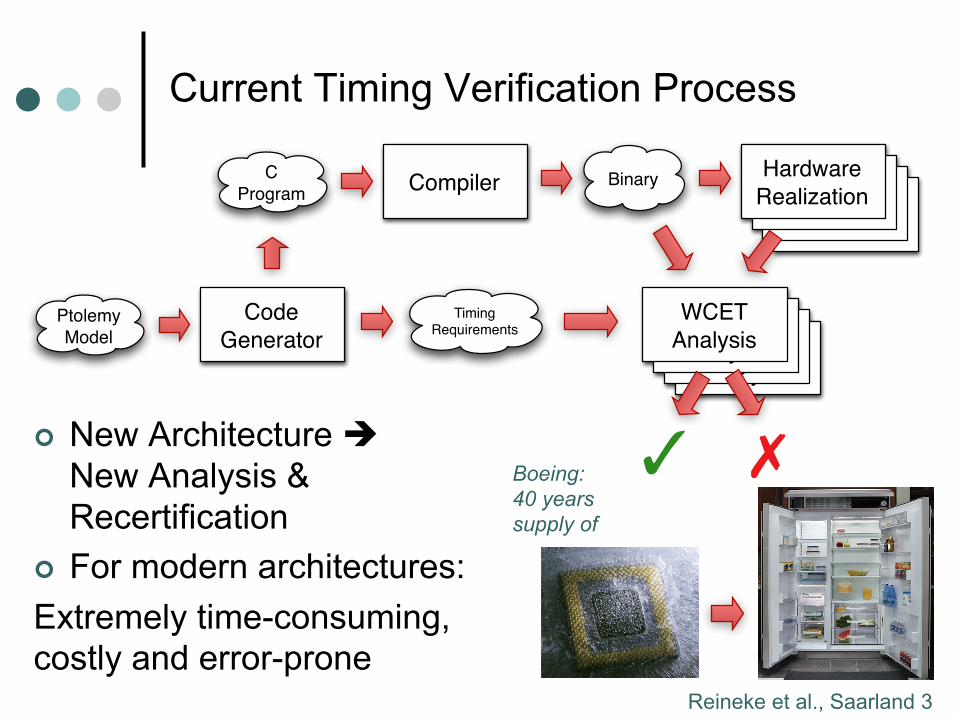
Current Timing Verification Process
¢ New Architecture è New Analysis & Recertification
¢ For modern architectures: Extremely time-consuming, costly and error-prone
Boeing: 40 years supply of
Reineke et al., Saarland 4
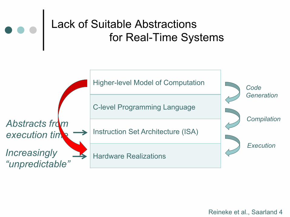
Lack of Suitable Abstractions for Real-Time Systems
Higher-level Model of Computation
C-level Programming Language
Instruction Set Architecture (ISA)
Hardware Realizations
Code Generation
Compilation
Execution
Abstracts from execution time
Increasingly “unpredictable”
Reineke et al., Saarland 5
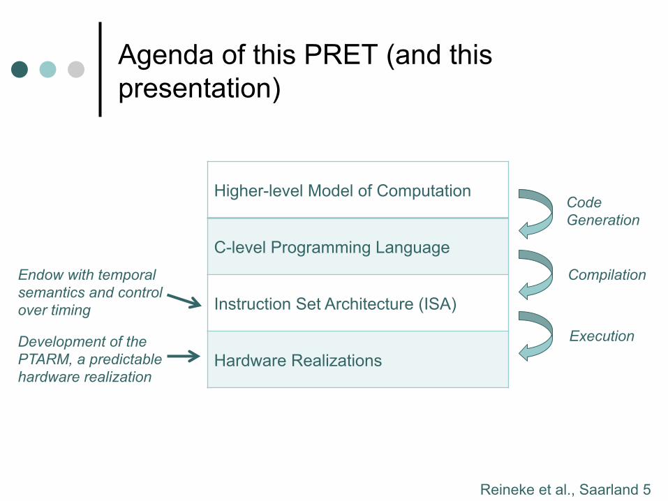
Agenda of this PRET (and this presentation)
Higher-level Model of Computation
C-level Programming Language
Instruction Set Architecture (ISA)
Hardware Realizations
Code Generation
Compilation
Execution
Endow with temporal semantics and control over timing
Development of the PTARM, a predictable hardware realization
Reineke et al., Saarland 6
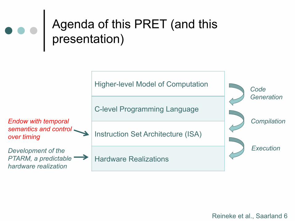
Agenda of this PRET (and this presentation)
Higher-level Model of Computation
C-level Programming Language
Instruction Set Architecture (ISA)
Hardware Realizations
Code Generation
Compilation
Execution
Endow with temporal semantics and control over timing
Development of the PTARM, a predictable hardware realization
Reineke et al., Saarland 7
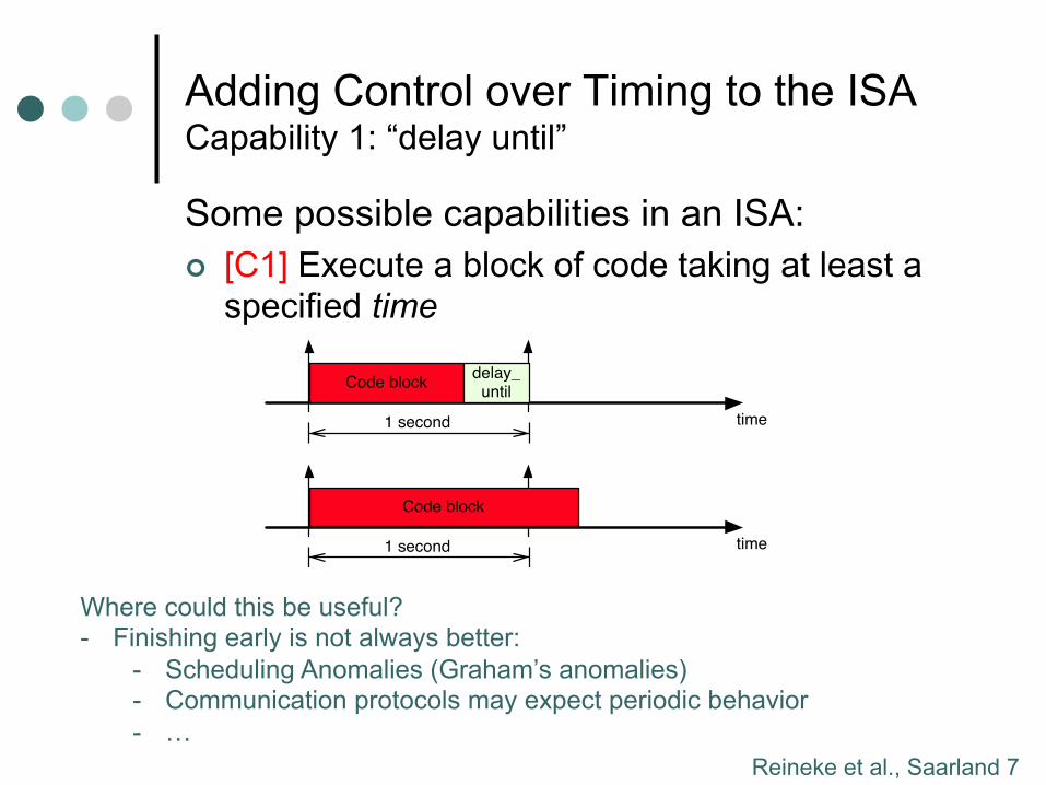
Adding Control over Timing to the ISA Capability 1: “delay until”
Some possible capabilities in an ISA: ¢ [C1] Execute a block of code taking at least a
specified time
time1 second
Code blockdelay_
until
time1 second
Code block
Where could this be useful? - Finishing early is not always better:
- Scheduling Anomalies (Graham’s anomalies) - Communication protocols may expect periodic behavior - …
Reineke et al., Saarland 8
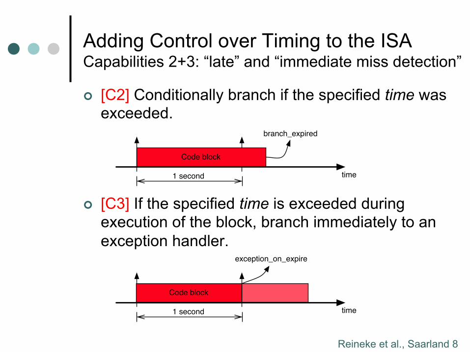
Adding Control over Timing to the ISA Capabilities 2+3: “late” and “immediate miss detection”
¢ [C2] Conditionally branch if the specified time was exceeded.
¢ [C3] If the specified time is exceeded during execution of the block, branch immediately to an exception handler.
time1 second
Code block
branch_expired
time1 second
Code block
exception_on_expire
Reineke et al., Saarland 9
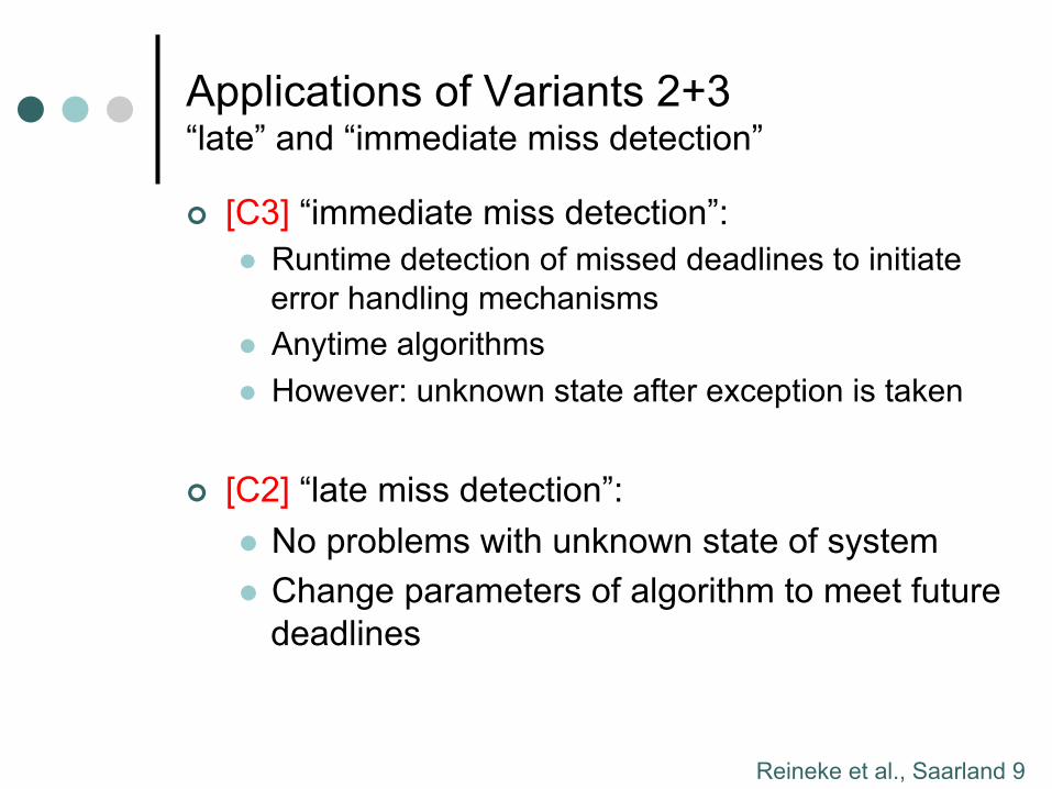
Applications of Variants 2+3 “late” and “immediate miss detection”
¢ [C3] “immediate miss detection”: l Runtime detection of missed deadlines to initiate
error handling mechanisms l Anytime algorithms l However: unknown state after exception is taken
¢ [C2] “late miss detection”: l No problems with unknown state of system l Change parameters of algorithm to meet future
deadlines
Reineke et al., Saarland 10
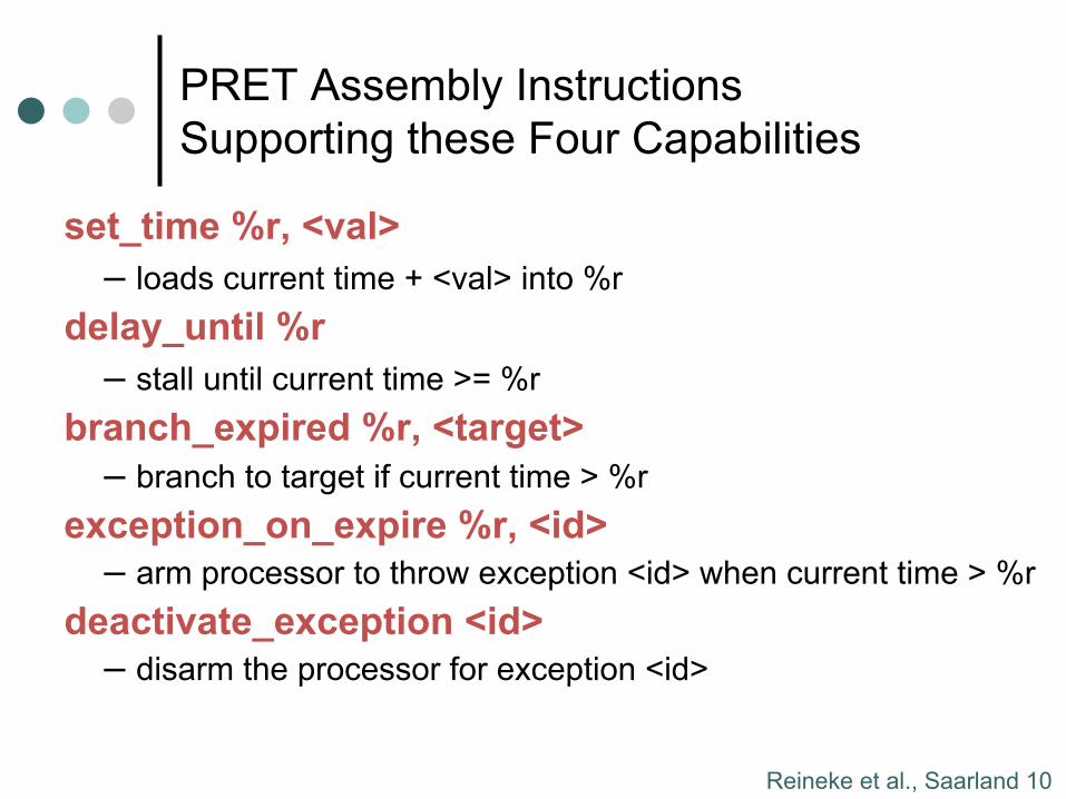
PRET Assembly Instructions Supporting these Four Capabilities
set_time %r, <val> – loads current time + <val> into %r
delay_until %r – stall until current time >= %r
branch_expired %r, <target> – branch to target if current time > %r
exception_on_expire %r, <id> – arm processor to throw exception <id> when current time > %r
deactivate_exception <id> – disarm the processor for exception <id>
Reineke et al., Saarland 11
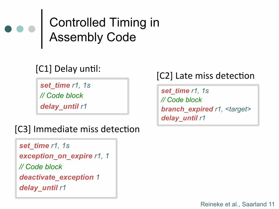
Controlled Timing in Assembly Code
[C1] Delay un-l: set_time r1, 1s // Code block delay_until r1
[C2] Late miss detec-on set_time r1, 1s // Code block branch_expired r1, <target> delay_until r1
set_time r1, 1s exception_on_expire r1, 1 // Code block deactivate_exception 1 delay_until r1
[C3] Immediate miss detec-on
Reineke et al., Saarland 12
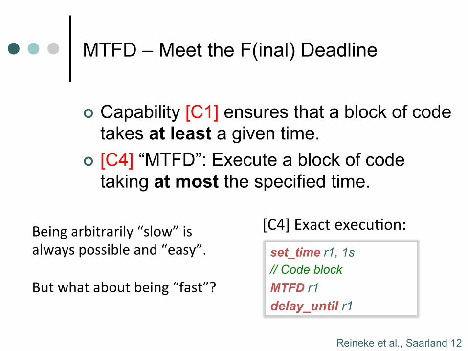
MTFD – Meet the F(inal) Deadline
¢ Capability [C1] ensures that a block of code takes at least a given time.
¢ [C4] “MTFD”: Execute a block of code taking at most the specified time.
[C4] Exact execu-on: set_time r1, 1s // Code block MTFD r1 delay_until r1
Being arbitrarily “slow” is always possible and “easy”. But what about being “fast”?
Reineke et al., Saarland 13
Current Timing Verification Process
¢ New Architecture è Recertification
¢ Extremely time-consuming and costly
WCET
Analysis
WCET
Analysis
WCET
Analysis
ArchitectureArchitecture
ArchitectureHardware
Realization
WCET
Analysis
C
ProgramBinaryCompiler
✓ ✗
Ptolemy
Model
Code
Generator
Timing Requirements
Reineke et al., Saarland 14
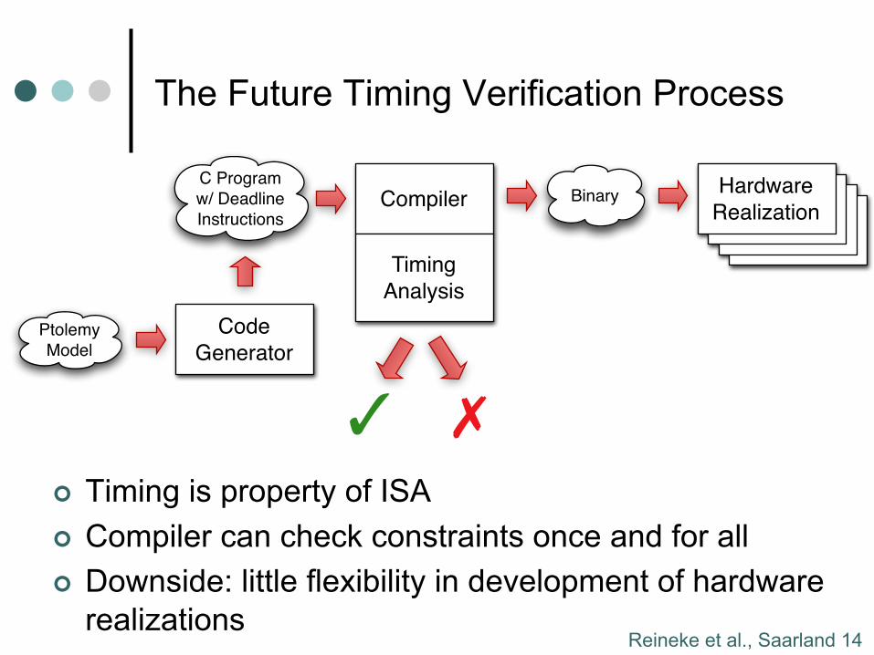
The Future Timing Verification Process
¢ Timing is property of ISA ¢ Compiler can check constraints once and for all ¢ Downside: little flexibility in development of hardware
realizations
ArchitectureArchitecture
Architecture
C Program
w/ Deadline
Instructions
BinaryHardware
RealizationCompiler
✓ ✗
Timing
Analysis
Ptolemy
Model
Code
Generator
Reineke et al., Saarland 15
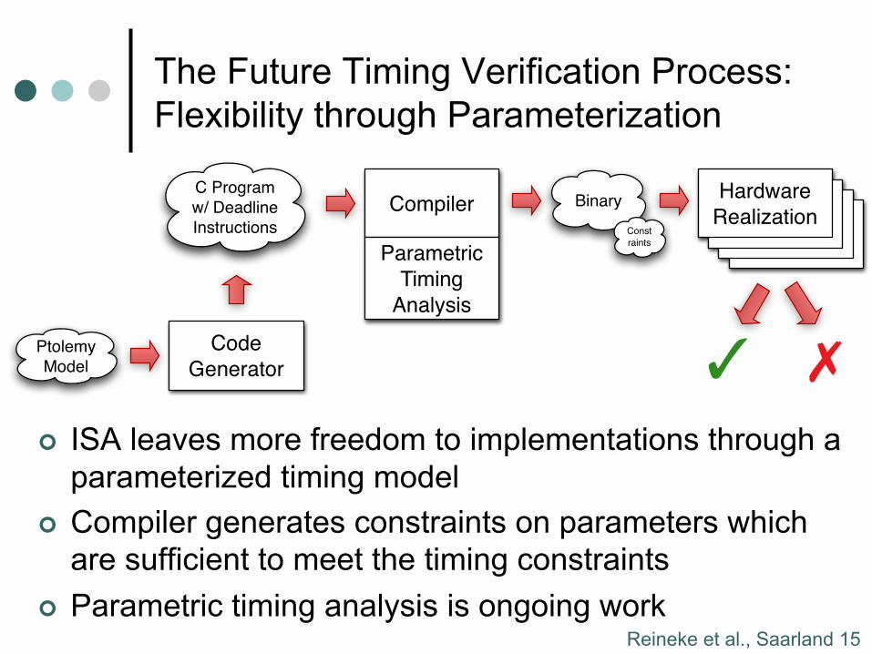
The Future Timing Verification Process: Flexibility through Parameterization
¢ ISA leaves more freedom to implementations through a parameterized timing model
¢ Compiler generates constraints on parameters which are sufficient to meet the timing constraints
¢ Parametric timing analysis is ongoing work
ArchitectureArchitecture
Architecture
C Program
w/ Deadline
Instructions
BinaryHardware
RealizationCompiler
✓ ✗
Const
raints
Parametric
Timing
Analysis
Ptolemy
Model
Code
Generator
Reineke et al., Saarland 16
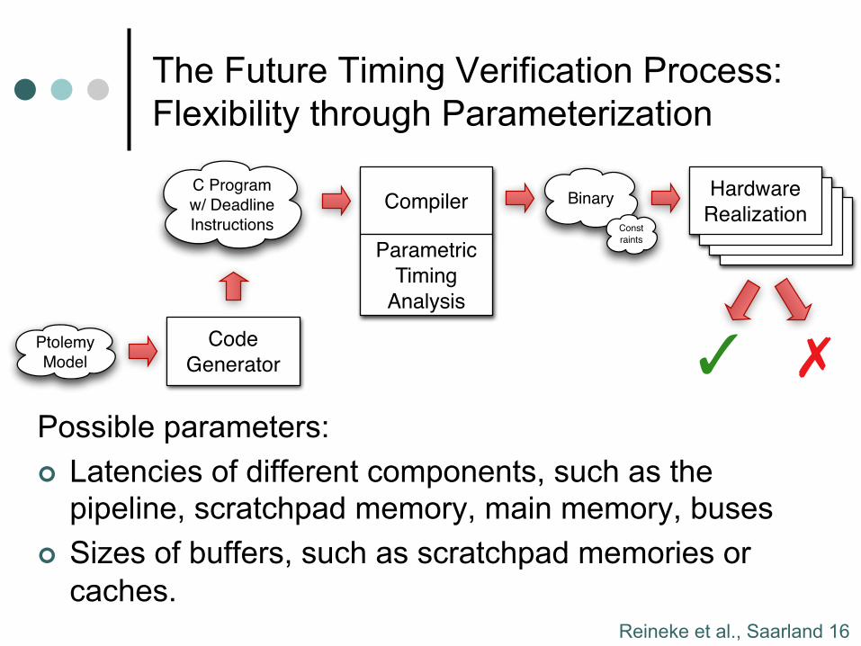
The Future Timing Verification Process: Flexibility through Parameterization
Possible parameters: ¢ Latencies of different components, such as the
pipeline, scratchpad memory, main memory, buses ¢ Sizes of buffers, such as scratchpad memories or
caches.
ArchitectureArchitecture
Architecture
C Program
w/ Deadline
Instructions
BinaryHardware
RealizationCompiler
✓ ✗
Const
raints
Parametric
Timing
Analysis
Ptolemy
Model
Code
Generator
Reineke et al., Saarland 17
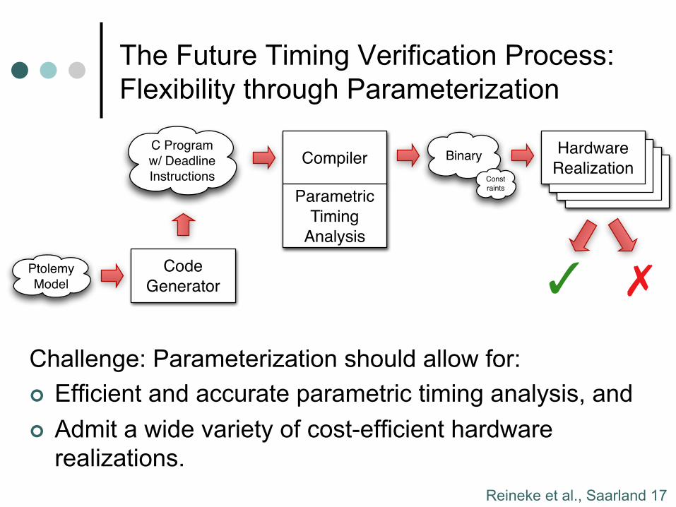
The Future Timing Verification Process: Flexibility through Parameterization
Challenge: Parameterization should allow for: ¢ Efficient and accurate parametric timing analysis, and ¢ Admit a wide variety of cost-efficient hardware
realizations.
ArchitectureArchitecture
Architecture
C Program
w/ Deadline
Instructions
BinaryHardware
RealizationCompiler
✓ ✗
Const
raints
Parametric
Timing
Analysis
Ptolemy
Model
Code
Generator
Reineke et al., Saarland 18
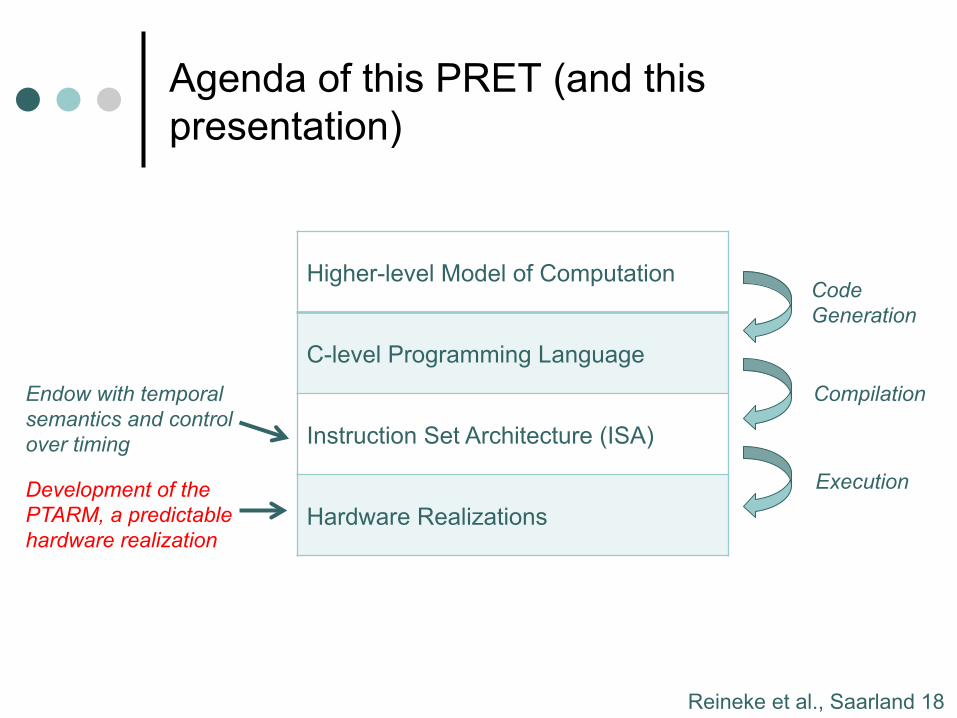
Agenda of this PRET (and this presentation)
Higher-level Model of Computation
C-level Programming Language
Instruction Set Architecture (ISA)
Hardware Realizations
Code Generation
Compilation
Execution
Endow with temporal semantics and control over timing
Development of the PTARM, a predictable hardware realization
Reineke et al., Saarland 19
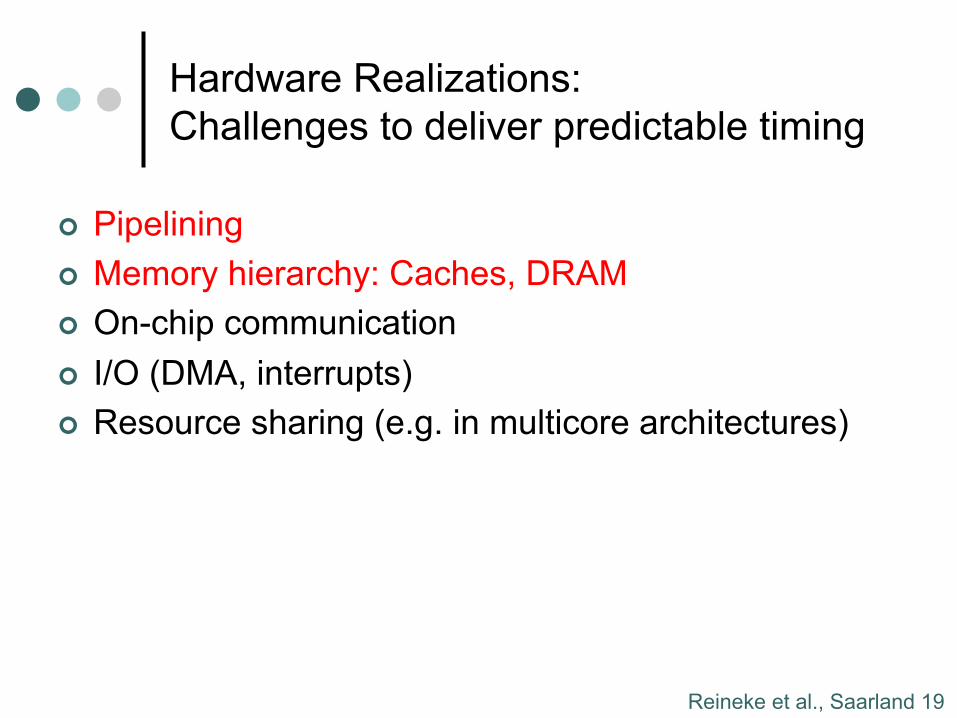
Hardware Realizations: Challenges to deliver predictable timing
¢ Pipelining ¢ Memory hierarchy: Caches, DRAM ¢ On-chip communication ¢ I/O (DMA, interrupts) ¢ Resource sharing (e.g. in multicore architectures)
Reineke et al., Saarland 20
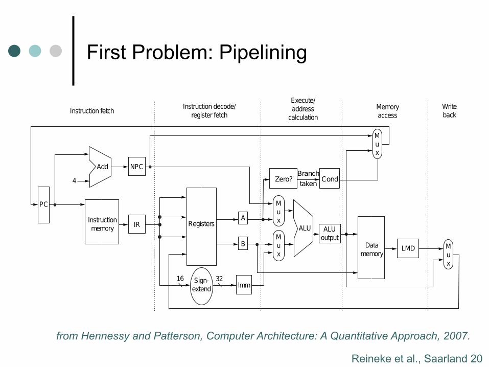
First Problem: Pipelining Processor Design 101
Hennessey and Patterson, Computer Architecture: A Quantitative Approach, 2007.from Hennessy and Patterson, Computer Architecture: A Quantitative Approach, 2007.
Reineke et al., Saarland 21
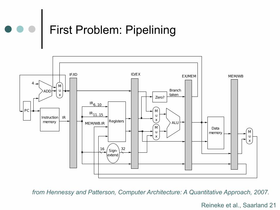
First Problem: Pipelining
from Hennessy and Patterson, Computer Architecture: A Quantitative Approach, 2007.
Pipeline It!
Hennessey and Patterson, Computer Architecture: A Quantitative Approach, 2007.
Reineke et al., Saarland 22
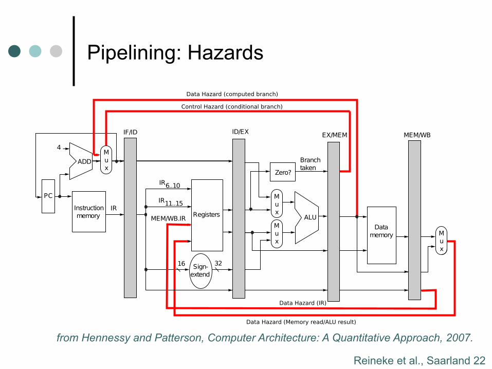
Pipelining: Hazards
from Hennessy and Patterson, Computer Architecture: A Quantitative Approach, 2007.
Great Except for Hazards
Hennessey and Patterson, Computer Architecture: A Quantitative Approach, 2007.
Reineke et al., Saarland 23
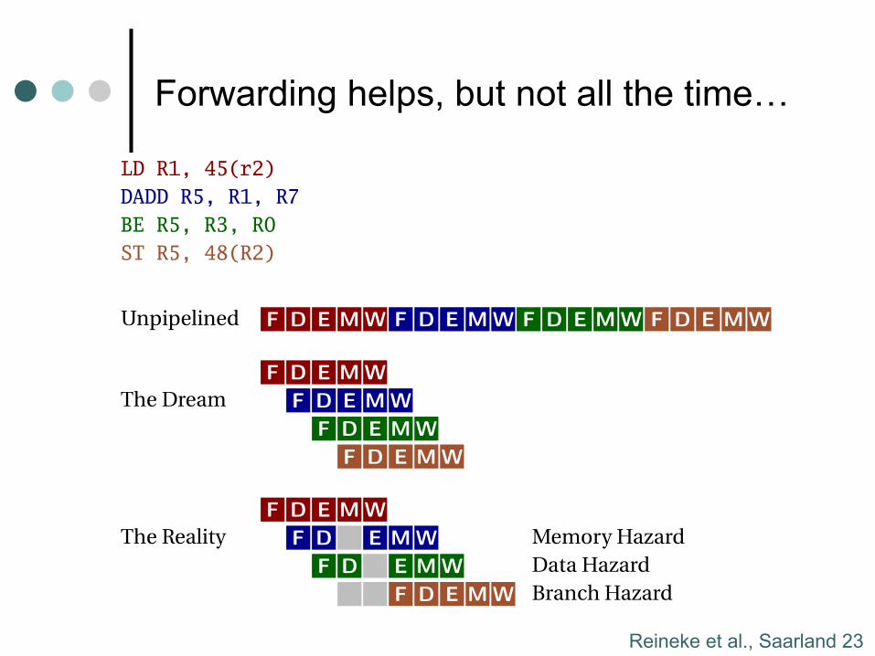
Forwarding helps, but not all the time… ...But It Does Not Solve Everything...
LD R1, 45(r2)
DADD R5, R1, R7
BE R5, R3, R0
ST R5, 48(R2)
Unpipelined F D E M W F D E M W F D E M W F D E M W
F D E M W
The Dream F D E M W
F D E M W
F D E M W
F D E M W
The Reality F D E M W Memory Hazard
F D E M W Data Hazard
F D E M W Branch Hazard
Reineke et al., Saarland 24
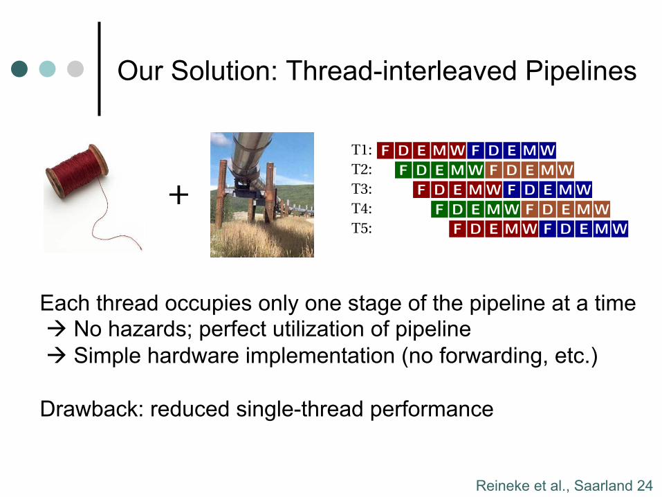
Our Solution: Thread-interleaved Pipelines
Our Solution: Thread-Interleaved Pipelines
+
An old idea from the 1960s
T1: F D E M W F D E M W
T2: F D E M W F D E M W
T3: F D E M W F D E M W
T4: F D E M W F D E M W
T5: F D E M W F D E M W
But what about memory?
Lee and Messerschmitt,Pipeline InterleavedProgrammable DSPs,ASSP-35(9), 1987.
Our Solution: Thread-Interleaved Pipelines
+
An old idea from the 1960s
T1: F D E M W F D E M W
T2: F D E M W F D E M W
T3: F D E M W F D E M W
T4: F D E M W F D E M W
T5: F D E M W F D E M W
But what about memory?
Lee and Messerschmitt,Pipeline InterleavedProgrammable DSPs,ASSP-35(9), 1987.
Each thread occupies only one stage of the pipeline at a time à No hazards; perfect utilization of pipeline à Simple hardware implementation (no forwarding, etc.) Drawback: reduced single-thread performance
Reineke et al., Saarland 25
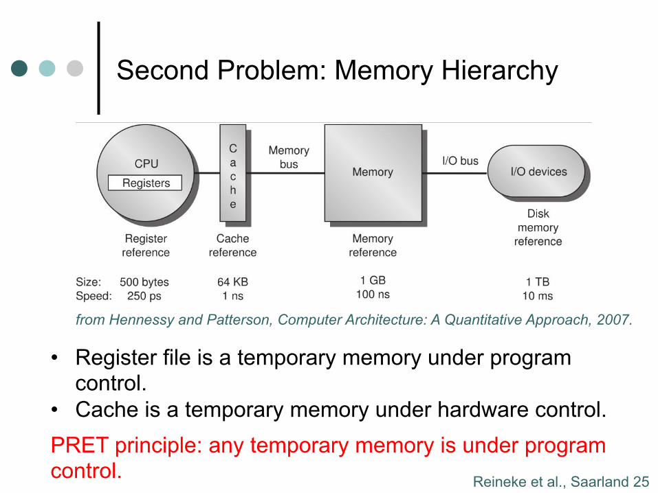
Second Problem: Memory Hierarchy
Lee, Berkeley 21
Second Problem: Memory Hierarchy
Register file is a temporary memory under program control.
Why is it so small?
Cache is a temporary memory under hardware control.
Why is replacement strategy application independent?
PRET principle: any temporary memory is under program
control.
Hennessey and Patterson, Computer Architecture: A Quantitative Approach, 4th edition, 2007.
Instruction word size.
Separation of concerns.
from Hennessy and Patterson, Computer Architecture: A Quantitative Approach, 2007.
• Register file is a temporary memory under program control.
• Cache is a temporary memory under hardware control. PRET principle: any temporary memory is under program control.
Reineke et al., Saarland 26
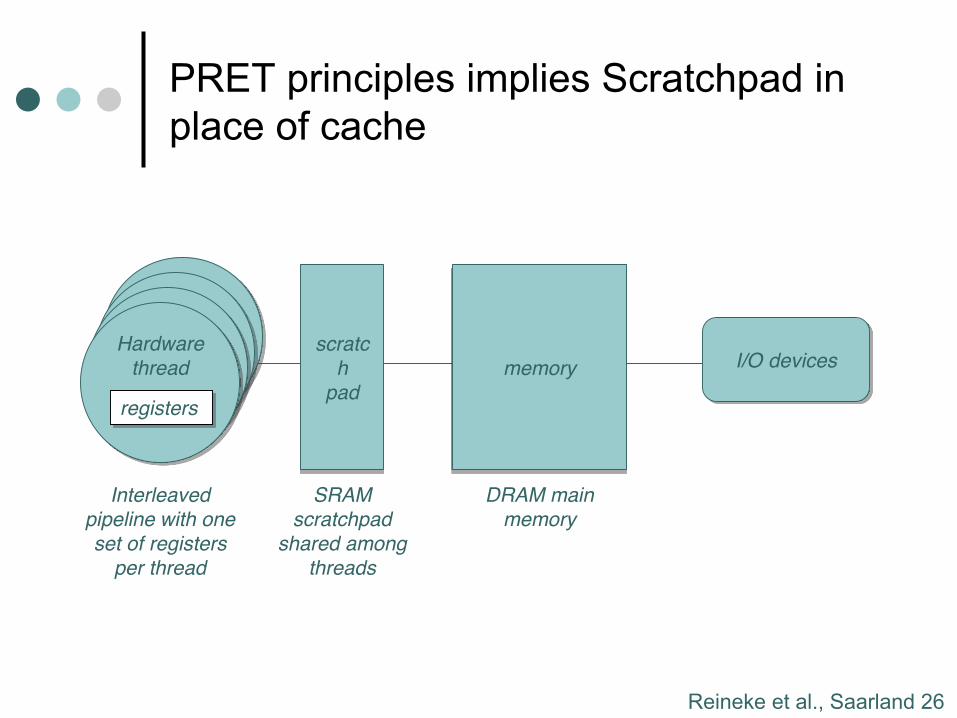
PRET principles implies Scratchpad in place of cache
Lee, Berkeley 22
Hardware
threadHardware
threadHardware
thread
PRET principle implies using a
scratchpad rather than a cache.
Hardware
thread
registers
scratc
h
pad
memory I/O devices
Interleaved
pipeline with one
set of registers
per thread
SRAM
scratchpad
shared among
threads
DRAM main
memory
Reineke et al., Saarland 27
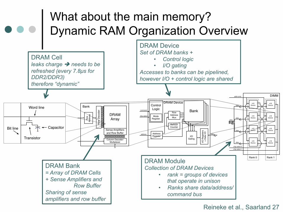
What about the main memory? Dynamic RAM Organization Overview
DIMMaddr+cmd
chip select 0
16
data
chip select 1
x16
Device
16
data
16
data
16
data
x16
Device
x16
Device
x16
Device
x16
Device
x16
Device
x16
Device
x16
Device
64
data
Rank 0 Rank 1
address
I/O
Re
gis
ters
+
Da
ta I
/OAddress Register
Control
Logic
Mode Register
16
data
command
chip select
DRAM Device
BankBankBankBankRow
Address Mux
RefreshCounter
I/O Gating
DRAM Array
Row
Decoder
Sense Amplifiers
and Row Buffer
Column Decoder/Multiplexer
Ro
w
Ad
dre
ss
Bank
CapacitorBit line
Word line
Transistor
Capacitor
DRAM Device Set of DRAM banks +
• Control logic • I/O gating
Accesses to banks can be pipelined, however I/O + control logic are shared
DRAM Cell leaks charge è needs to be refreshed (every 7.8µs for DDR2/DDR3) therefore “dynamic”
DRAM Bank = Array of DRAM Cells + Sense Amplifiers and
Row Buffer Sharing of sense amplifiers and row buffer
DRAM Module Collection of DRAM Devices
• rank = groups of devices that operate in unison
• Ranks share data/address/command bus
Reineke et al., Saarland 28
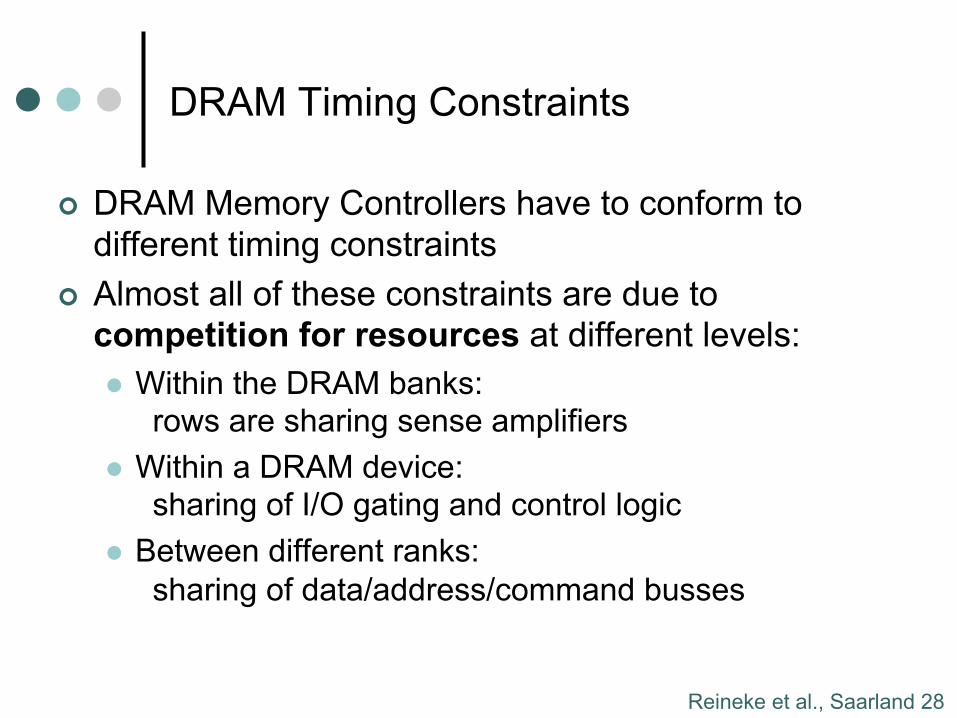
DRAM Timing Constraints
¢ DRAM Memory Controllers have to conform to different timing constraints
¢ Almost all of these constraints are due to competition for resources at different levels: l Within the DRAM banks:
rows are sharing sense amplifiers l Within a DRAM device:
sharing of I/O gating and control logic l Between different ranks:
sharing of data/address/command busses
Reineke et al., Saarland 29
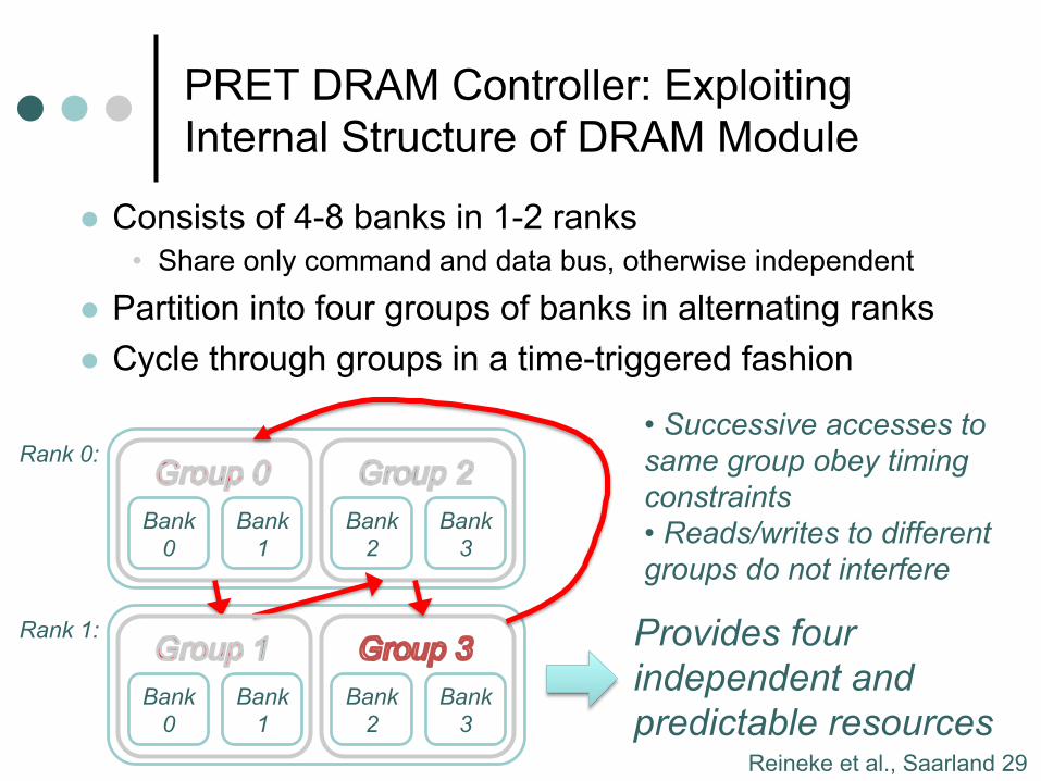
PRET DRAM Controller: Exploiting Internal Structure of DRAM Module
l Consists of 4-8 banks in 1-2 ranks • Share only command and data bus, otherwise independent
l Partition into four groups of banks in alternating ranks l Cycle through groups in a time-triggered fashion
Bank 0
Bank 1
Bank 2
Bank 3
Rank 0:
Bank 0
Bank 1
Bank 2
Bank 3
Rank 1:
• Successive accesses to same group obey timing constraints • Reads/writes to different groups do not interfere
Provides four independent and predictable resources
Reineke et al., Saarland 30
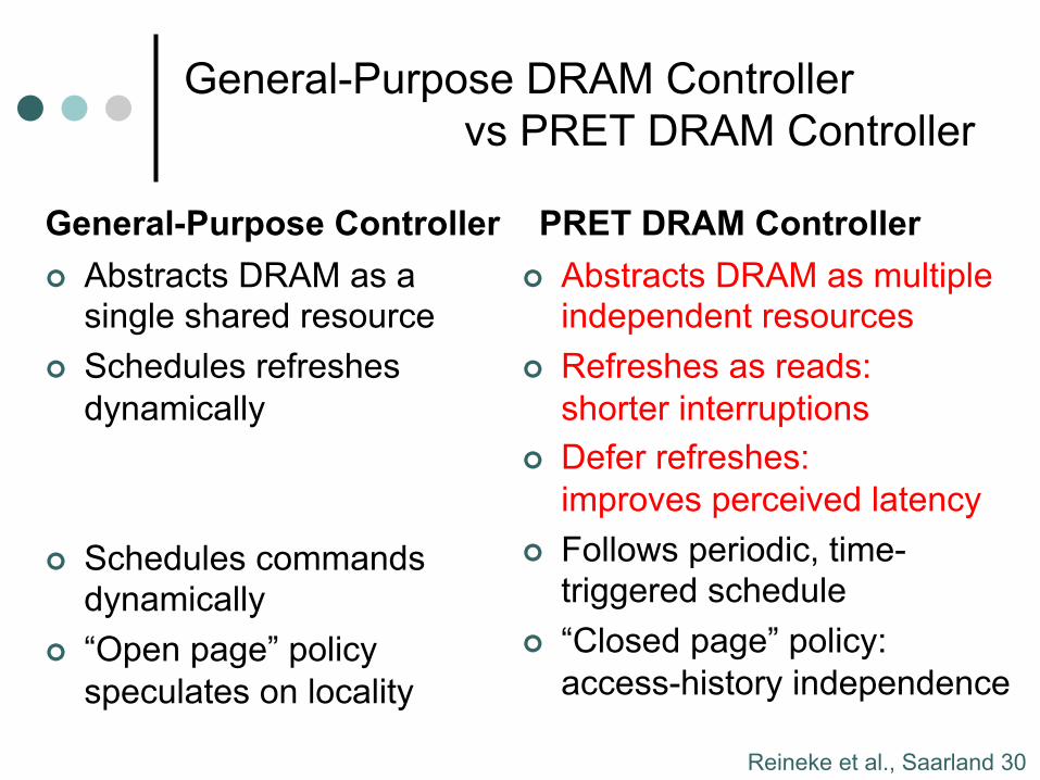
General-Purpose DRAM Controller vs PRET DRAM Controller
General-Purpose Controller ¢ Abstracts DRAM as a
single shared resource ¢ Schedules refreshes
dynamically
¢ Schedules commands dynamically
¢ “Open page” policy speculates on locality
PRET DRAM Controller ¢ Abstracts DRAM as multiple
independent resources ¢ Refreshes as reads:
shorter interruptions ¢ Defer refreshes:
improves perceived latency ¢ Follows periodic, time-
triggered schedule ¢ “Closed page” policy:
access-history independence
Reineke et al., Saarland 31
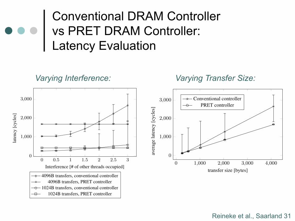
Conventional DRAM Controller vs PRET DRAM Controller: Latency Evaluation
256 512 768 1,024 1,280 1,536 1,792 2,0480
200
400
600
800 Benefit of burst length 8 over burst length 4
size of transfer [bytes]
late
ncy
[cyc
les]
Shared Predator, BL = 4, accounting for all refreshesDLr(x): PRET, BL = 4, accounting for all refreshesShared Predator, BL = 8, accounting for all refreshesDLr(x): PRET, BL = 8, accounting for all refreshes
Figure 8: Latencies of Predator and PRET for request sizes upto 2KB under burst lengths 4 and 8.
5.4 BandwidthWe describe the peak bandwidth achieved by the PRET DRAM
controller. In the case of the burst length being 4, disregardingrefreshes, we send out four CAS commands every 13 cycles. EachCAS results in a transfer of a burst of size 8 ·4 = 32 bytes over theperiod of two cycles5. The memory controller and the data bus arerunning at a frequency of 200 MHz. So, disregarding refreshes thecontroller would provide a bandwidth of 200 MHz· 4
13 · 32 bytes ⇥1.969GB/s. We issue a refresh command in every 60th slot. Thisreduces the available bandwidth to 59
60 · 1.969GB/s ⇥ 1.936GB/s,which are 60.5% of the data bus bandwidth.
For burst length 8, we transfer 8 · 8 = 64 bytes every five cyclesand perform a refresh in every 39th slot, resulting in an availablebandwidth of 200MHz · 38
39 ·15 · 64 bytes ⇥ 2.494GB/s, or 77.95%
of the data bus bandwidth.
6. EXPERIMENTAL EVALUATIONWe present experimental results to verify that the design of the
PRET DRAM controller honors the derived analytical bounds. Wehave implemented the PRET DRAM controller, and compare itvia simulation with a conventional DRAM controller. We use thePTARM simulator6 and extend it to interface with both memorycontrollers to run synthetic benchmarks that simulate memory ac-tivity. The PTARM simulator is a C++ simulator that simulatesthe PRET architecture with four hardware threads running througha thread-interleaved pipeline. We use a C++ wrapper around theDRAMSim2 simulator [17] to simulate memory access latenciesfrom a conventional DRAM controller. A first-come, first-servedqueuing scheme is used to queue up memory requests to the DRAM-Sim2 simulator. The PRET DRAM controller was also written inC++ based on the description in Section 4. The benchmarks we useare all written in C, and compiled using the GNU ARM cross com-piler. The DMA transfer latencies that are measured begin whenthe DMA unit issues its first request and end when the last requestfrom the DMA unit is completed.
6.1 Experimental ResultsWe setup our experiment to show the effects of interference on
memory access latency for both memory controllers. We first setupour main thread to run different programs that initiate fixed-size
5In double-data rate (DDR) memory two transfers are performedper clock cycle.6The PTARM simulator is available for download at http://chess.eecs.berkeley.edu/pret/release/ptarm.
0 0.5 1 1.5 2 2.5 30
1,000
2,000
3,000
Interference [# of other threads occupied]
late
ncy
[cyc
les]
4096B transfers, conventional controller4096B transfers, PRET controller
1024B transfers, conventional controller1024B transfers, PRET controller
Figure 9: Latencies of conventional and PRET memory con-troller with varying interference from other threads.
DMA transfers (256, 512, 1024, 2048 and 4096 bytes) at randomintervals. The DMA latencies of the main thread is what is mea-sured and shown in Figure 9 and Figure 10. To introduce interfer-ence within the system, we run a combination of two programs onthe other hardware threads in PTARM simulator. The first programcontinuously issues DMA requests of large size (4096 bytes) in or-der to fully utilize the memory bandwidth. The second programutilizes half the memory bandwidth by issuing DMA requests ofsize 4096 bytes half as frequently as the first program. In Figure 9,we define thread occupancy on the x-axis as the memory bandwidthoccupied by the combination of all threads. 0.5 means we have onethread running the second program along side the main thread. 1.0means we have one thread running the first program along side themain thread. 1.5 means we have one thread running the first pro-gram, one thread running the second program, and both threads arerunning along side the main thread, and so on. 3 is the maximumwe can achieve because the PTARM simulator has a total of fourhardware threads (the main thread occupies one of the four). Wemeasured the latency of each fixed size transfer for the main threadto observe the transfer latency in the presence of interference frommemory requests by other threads.
In Figure 9, we show measurements taken from two differentDMA transfer sizes, 1024 and 4096 bytes. The marks in the figureshow the average latency measured over 1000 iterations. The errorbars above and below the marks show the worst-case and best-caselatencies of each transfer size over the same 1000 iterations. In bothcases, without any interference, the conventional DRAM controllerprovides better access latencies. This is because without any inter-ference, the conventional DRAM controller can often exploit rowlocality and service requests immediately. The PRET DRAM con-troller on the other hand uses the periodic pipelined access scheme,thus even though no other threads are accessing memory, the mem-ory requests still need to wait for their slot to get access to theDRAM. However, as interference is gradually introduced, we ob-serve increases in latency for the conventional DRAM controller.This could be caused by the first-come, first-served buffer, or bythe internal queueing and handling of requests by DRAMSim2.The PRET DRAM controller however is unaffected by the inter-ference created by the other threads. In fact, the latency valuesthat were measured from the PRET DRAM controller remain the
0 1,000 2,000 3,000 4,000
0
1,000
2,000
3,000
transfer size [bytes]
aver
age
late
ncy
[cyc
les]
Conventional controllerPRET controller
Figure 10: Latencies of conventional and PRET memory con-troller with maximum load by interfering threads and varyingtransfer size.
same under all different thread occupancies. This demonstrates thetemporal isolation achieved by the PRET DRAM controller. Anytiming analysis on the memory latency for one thread only needsto be done in the context of that thread. We also see the range ofmemory latencies for the conventional DRAM controller increaseas the interference increases. But the range of access latencies forthe PRET DRAM controller not only remains the same through-out, but is almost negligible for both transfer sizes7. This shows thepredictable nature of the PRET DRAM controller.
In Figure 10 we show the memory latencies under full load (threadoccupancy of 3) for different transfer sizes. This figure shows thatunder maximum interference from the other hardware threads, thePRET DRAM controller is less affected by interference even astransfer sizes increase. More importantly, when we compare thenumbers from Figure 10 to Figure 8, we confirm that the theoret-ical bandwidth calculations hold even under maximum bandwidthstress from the other threads.
7. CONCLUSIONS AND FUTURE WORKIn this paper we presented a DRAM controller design that is
predictable with significantly reduced worst-case access latencies.Our approach views the DRAM device as multiple independent re-sources that are accessed in a periodic pipelined fashion. This elim-inates contention for shared resources within the device to providetemporally predictable and isolated memory access latencies. Werefresh the DRAM through row accesses instead of standard re-freshes. This results in improved worst-case access latency at aslight loss of bandwidth. Latency bounds for our memory con-troller, determined analytically and confirmed through simulation,show that our controller is both timing predictable and providestemporal isolation for memory accesses from different resources.
Thought-provoking challenges remain in the development of anefficient, yet predictable memory hierarchy. In conventional multi-core architectures, local memories such as caches or scratchpadsare private, while access to the DRAM is shared. However, inthe thread-interleaved PTARM, the instruction and data scratchpadmemories are shared, while access to the DRAM is not. We havedemonstrated the advantages of privatizing parts of the DRAM forworst-case latency. It will be interesting to explore the consequencesof the inverted sharing structure on the programming model.
We envision adding instructions to the PTARM that allow threadsto pass ownership of DRAM resources to other threads. This would,
7The range (worst-case latency - best-case latency) was approxi-mately 90ns for 4096 bytes transfers and approximately 20ns for1024 byte transfers.
for instance, allow for extremely efficient double-buffering imple-mentations. We also plan to develop new scratchpad allocationtechniques, which use the PTARM’s DMA units to hide memorylatencies, and which take into account the transfer-size dependentlatency bounds derived in this paper.
8. REFERENCES[1] B. Akesson, K. Goossens, and M. Ringhofer, “Predator: a
predictable SDRAM memory controller,” in CODES+ISSS.ACM, 2007, pp. 251–256.
[2] B. Akesson, “Predictable and composable system-on-chipmemory controllers,” Ph.D. dissertation, EindhovenUniversity of Technology, Feb. 2010.
[3] M. Paolieri, E. Quiñones, F. Cazorla, and M. Valero, “Ananalyzable memory controller for hard real-time CMPs,”IEEE Embedded Systems Letters, vol. 1, no. 4, pp. 86–90,2010.
[4] I. Liu, J. Reineke, and E. A. Lee, “A PRET architecturesupporting concurrent programs with composable timingproperties,” in 44th Asilomar Conference on Signals,Systems, and Computers, November 2010.
[5] S. A. Edwards and E. A. Lee, “The case for the precisiontimed (PRET) machine,” in DAC. New York, NY, USA:ACM, 2007, pp. 264–265.
[6] D. Bui, E. A. Lee, I. Liu, H. D. Patel, and J. Reineke,“Temporal isolation on multiprocessing architectures,” inDAC. ACM, June 2011.
[7] B. Jacob, S. W. Ng, and D. T. Wang, Memory Systems:Cache, DRAM, Disk. Morgan Kaufmann Publishers,September 2007.
[8] JEDEC, DDR2 SDRAM SPECIFICATION JESD79-2E.,2008.
[9] B. Akesson, L. Steffens, E. Strooisma, and K. Goossens,“Real-time scheduling using credit-controlled static-priorityarbitration,” in RTCSA, Aug. 2008, pp. 3 –14.
[10] B. Bhat and F. Mueller, “Making DRAM refreshpredictable,” in ECRTS, 2010, pp. 145–154.
[11] P. Atanassov and P. Puschner, “Impact of DRAM refresh onthe execution time of real-time tasks,” in Proc. IEEEInternational Workshop on Application of ReliableComputing and Communication, Dec. 2001, pp. 29–34.
[12] R. Wilhelm et al., “Memory hierarchies, pipelines, and busesfor future architectures in time-critical embedded systems,”IEEE TCAD, vol. 28, no. 7, pp. 966–978, 2009.
[13] R. Bourgade, C. Ballabriga, H. Cassé, C. Rochange, andP. Sainrat, “Accurate analysis of memory latencies forWCET estimation,” in RTNS, Oct. 2008.
[14] T. Ungerer et al., “MERASA: Multi-core execution of hardreal-time applications supporting analysability,” IEEE Micro,vol. 99, 2010.
[15] M. Schoeberl, “A java processor architecture for embeddedreal-time systems,” Journal of Systems Architecture, vol. 54,no. 1-2, pp. 265 – 286, 2008.
[16] A. Hansson, K. Goossens, M. Bekooij, and J. Huisken,“CoMPSoC: A template for composable and predictablemulti-processor system on chips,” ACM TODAES, vol. 14,no. 1, pp. 1–24, 2009.
[17] P. Rosenfeld, E. Cooper-Balis, and B. Jacob, “DRAMSim2:A cycle accurate memory system simulator,” ComputerArchitecture Letters, vol. 10, no. 1, pp. 16 –19, Jan. 2011.
Varying Interference: Varying Transfer Size:
Reineke et al., Saarland 32
PRET DRAM Controller vs Predator
5.3.1 Derivation of Worst-case DMA LatenciesTo carry out a transfer of x bytes, a DMA unit needs to send�x
BL·8⇥
requests to the backend. It has to wait up to BEL cycles tosend the first request, then it can send requests every BP = 4 ·(1+BL2 ) cycles. BEL is at most BP . After sending the last request
to the backend, it takes DRL = 10 + BL2 cycles for the resulting
burst transfer to finish. Thus, the latency DL(x) of a transfer of xbytes from the DRAM in cycles of the memory controller is
DL(x) = BEL+BP ·⇤⌥ x
BL · 8
�� 1
⌅+DRL (4)
⇤ (4 + 2 ·BL) ·⌥ xBL · 8
�+ 10 +
BL2
. (5)
This equation, however, does not consider refreshes yet. Asnoted before, we associate two latencies with a DMA transfer:
1. The time DLr(x) from initiating the DMA transfer until thedata has been transferred, and is, e.g., available in the datascratchpad. The superscript r indicates that DLr(x) does notinclude the final refresh.
2. The time DLr(x) from initiating the DMA transfer until thethread-interleaved pipeline regains access to the DRAM. Thesuperscript r indicates that DLr(x) includes the final refresh.
One could further distinguish between transfers from DRAM toscratchpad and from scratchpad to DRAM. Due to space constraints,we only consider the former, which incurs higher latencies. DLr(x)can be computed from DL(x) by adding latency incurred by re-freshes beyond the first one, which will be accounted for in DLr(x):
DLr(x) = DL(x) +BP
⇧ �x
BL·8⇥
RFP � 1� 1
⌃(6)
= DL(x) + (4 + 2 ·BL)
⇧ �x
BL·8⇥
RFP � 1� 1
⌃(7)
where RFP is the refresh period. At burst length 4, RFP = 60,at burst length 8, RFP = 39. DLr(x) is simply DLr(x) +BP .
In order to assess the value of privatization, we also determinelatencies for a scenario in which the four resources of the backendare shared among four clients in a round-robin fashion. These fourclients could be the four threads of the PTARM or four cores in amulti-core processor. This shall also indicate whether the PRETDRAM controller is a viable option in such a scenario.
By DLn,s(x) we denote the latency of a transfer of size x, wherethe DMA unit has access to n resources, which are each sharedamong s clients. A transfer of size x will then be split up into ntransfers of size x/n. Due to the sharing of the resources, onlyevery sth access slot is available in each resource.
DLn,s(x) = s ·BP ·⌥ xn ·BL · 8
�+DRL (8)
= s · (4 + 2 ·BL) ·⌥ xn ·BL · 8
�+
BL2
+ 9. (9)
For space reasons, we limit our analysis to the second of the twolatencies associated with a DMA transfer, which is derived simi-larly to the non-shared case:
DLrn,s(x) = DLn,s(x) +BP
⇧s ·
�x
n·BL·8⇥
RFP � 1
⌃(10)
= DLn,s(x) + (4 + 2 ·BL)
⇧s ·
�x
n·BL·8⇥
RFP � 1
⌃.(11)
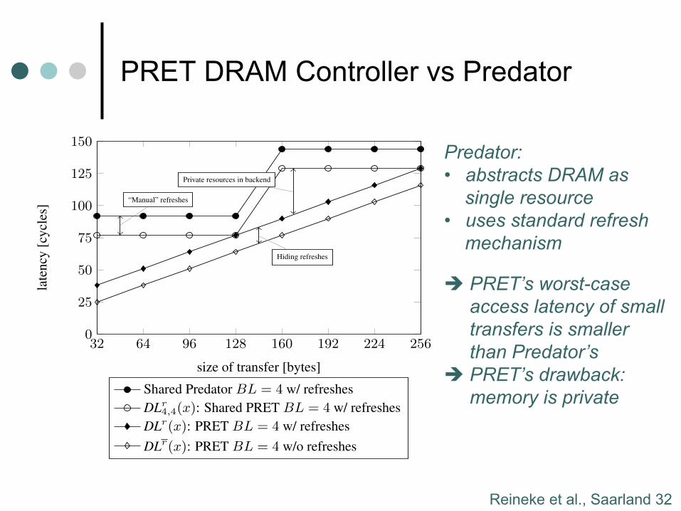
32 64 96 128 160 192 224 2560
25
50
75
100
125
150
“Manual” refreshes
Private resources in backend
Hiding refreshes
size of transfer [bytes]
late
ncy
[cyc
les]
Shared Predator BL = 4 w/ refreshesDLr
4,4(x): Shared PRET BL = 4 w/ refreshesDLr(x): PRET BL = 4 w/ refreshesDLr(x): PRET BL = 4 w/o refreshes
Figure 7: Latencies for small request sizes up to 256 bytes un-der Predator and PRET at burst length 4. In this, and all of thefollowing figures, one cycle corresponds to 5 ns.
5.3.2 Analysis of Worst-case DMA LatenciesFor comparison, we have also determined access latencies for
Predator based on Åkesson’s dissertation [2]. Figure 7 shows ac-cess latencies of PRET and Predator for transfers up to 256 bytes,as they frequently occur in fine-grained scratchpad allocation code,or when filling cache lines. We compare four scenarios involvingPRET and Predator:
1. DLr(x): Latencies of transfers using one of the four resourcesat burst length 4, excluding the cost of a final refresh.
2. DLr(x): Latencies of transfers using one of the four resourcesat burst length 4, including the cost of all refreshes.
3. DLr4,4(x): Latencies of transfers using all of the four re-
sources at burst length 4 shared among four clients (usinground-robin arbitration), including the cost of all refreshes.
4. Latencies of transfers using Predator at burst length 4 sharedamong four clients (using round-robin arbitration), includingthe cost of all refreshes.
Hiding refreshes (Scenario 1 vs Scenario 2) saves BP = 13cycles in all cases. The benefit of private resources can be seencomparing Scenario 2 with Scenario 3. When sharing all banks,the minimum transfer size is 128 bytes (one burst of 32 bytes toeach of the four resources). For transfer sizes that are not multiplesof this size, private resources reduce latency significantly. The mostextreme case is that of a 32-byte transfer where latency is reducedfrom 77 to 38 cycles. The slight advantage of shared PRET (Sce-nario 3) compared with shared Predator (Scenario 4) can mostly beexplained by the manual refresh mechanism employed in PRET.
For larger transfers, the bandwidth provided by the memory con-troller becomes more important, and private DRAM resources areless beneficial. This is illustrated in Figure 8. For both burst length4 and 8, PRET and Predator show very similar latencies. Predator’sslightly flatter slope is due to fewer read/write switches and the useof the standard refresh mechanism, which adversely affects laten-cies of small transfers. For 2 KB transfers, burst length 8 reduceslatency by approximately 22% compared with burst length 4.
Predator: • abstracts DRAM as
single resource • uses standard refresh
mechanism è PRET’s worst-case
access latency of small transfers is smaller than Predator’s
è PRET’s drawback: memory is private
Reineke et al., Saarland 33
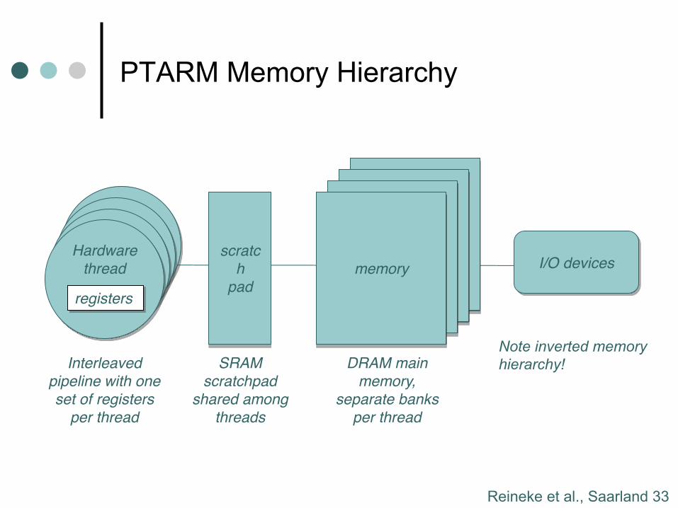
PTARM Memory Hierarchy
Lee, Berkeley 24
Hardware
threadHardware
threadHardware
thread
Resulting PRET ArchitectureWe have realized this in PTArm,
a soft core on a Xilinx Virtex 5 FPGA
Hardware
thread
registers
scratc
h
pad
memory
I/O devices
Interleaved
pipeline with one
set of registers
per thread
SRAM
scratchpad
shared among
threads
DRAM main
memory,
separate banks
per thread
memorymemory
memory
Note inverted memory
compared to multicore!
Fast, close memory is
shared, slow remote
memory is private!
Note inverted memory hierarchy!
Lee, Berkeley 34
Conclusions
¢ Real-time computing needs real-time abstractions
¢ Potential for significant improvements in worst-case performance of some hardware realizations
¢ For more information on PRET: Raffaello Sanzio da Urbino – The Athens School
http://chess.eecs.berkeley.edu/pret/
Reineke et al., Saarland 35
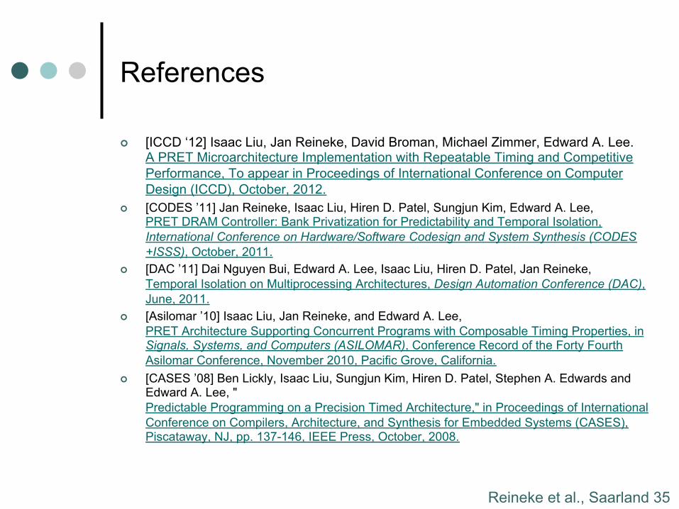
References
¢ [ICCD ‘12] Isaac Liu, Jan Reineke, David Broman, Michael Zimmer, Edward A. Lee. A PRET Microarchitecture Implementation with Repeatable Timing and Competitive Performance, To appear in Proceedings of International Conference on Computer Design (ICCD), October, 2012.
¢ [CODES ’11] Jan Reineke, Isaac Liu, Hiren D. Patel, Sungjun Kim, Edward A. Lee, PRET DRAM Controller: Bank Privatization for Predictability and Temporal Isolation, International Conference on Hardware/Software Codesign and System Synthesis (CODES+ISSS), October, 2011.
¢ [DAC ’11] Dai Nguyen Bui, Edward A. Lee, Isaac Liu, Hiren D. Patel, Jan Reineke, Temporal Isolation on Multiprocessing Architectures, Design Automation Conference (DAC), June, 2011.
¢ [Asilomar ’10] Isaac Liu, Jan Reineke, and Edward A. Lee, PRET Architecture Supporting Concurrent Programs with Composable Timing Properties, in Signals, Systems, and Computers (ASILOMAR), Conference Record of the Forty Fourth Asilomar Conference, November 2010, Pacific Grove, California.
¢ [CASES ’08] Ben Lickly, Isaac Liu, Sungjun Kim, Hiren D. Patel, Stephen A. Edwards and Edward A. Lee, "Predictable Programming on a Precision Timed Architecture," in Proceedings of International Conference on Compilers, Architecture, and Synthesis for Embedded Systems (CASES), Piscataway, NJ, pp. 137-146, IEEE Press, October, 2008.
Recommended