P104
10 -
09/1
3 - S
ubje
ct to
cha
nge.
© B
elim
o Ai
rcon
trols
(USA
), In
c.
Disadvantages of Today’s Systems
• Time consuming balancing effort
• Rebalancing required when adding to system or remodeling
• Poor valve authority at average or low load
• Balancing procedure dictates quality
• Low ΔT at the coils yields overfl ow and increases pumping costs
• Potential spreading of control problems can occur when one or moreloops are instable, due to interactive nature of circuits
Advantages of the PICCV
• Easy selection, no Cv calculation required
• Hydronic balancing is simplifi ed, as the circuits are not interactive
• Flexible commissioning
• One piece installation saves 50% of labor costs, installation space, andinvestment for balancing valve
• Reduces pumping costs by maintain fl ow regardless of pressure fl uctuations
• Visualizes fl ow in a BMS system and provides accurate fl ow for eachdegree of opening
• Prevents overfl ow or underfl ow for fast start-up
Options
• Belimo PC-Tool/ZTH-GEN US for commissioning
• Weather shields
• Auxiliary switches
• Flow verifi cation orifi ce (-F models) available only with fi eld set LRB24-SAand KRB24-3
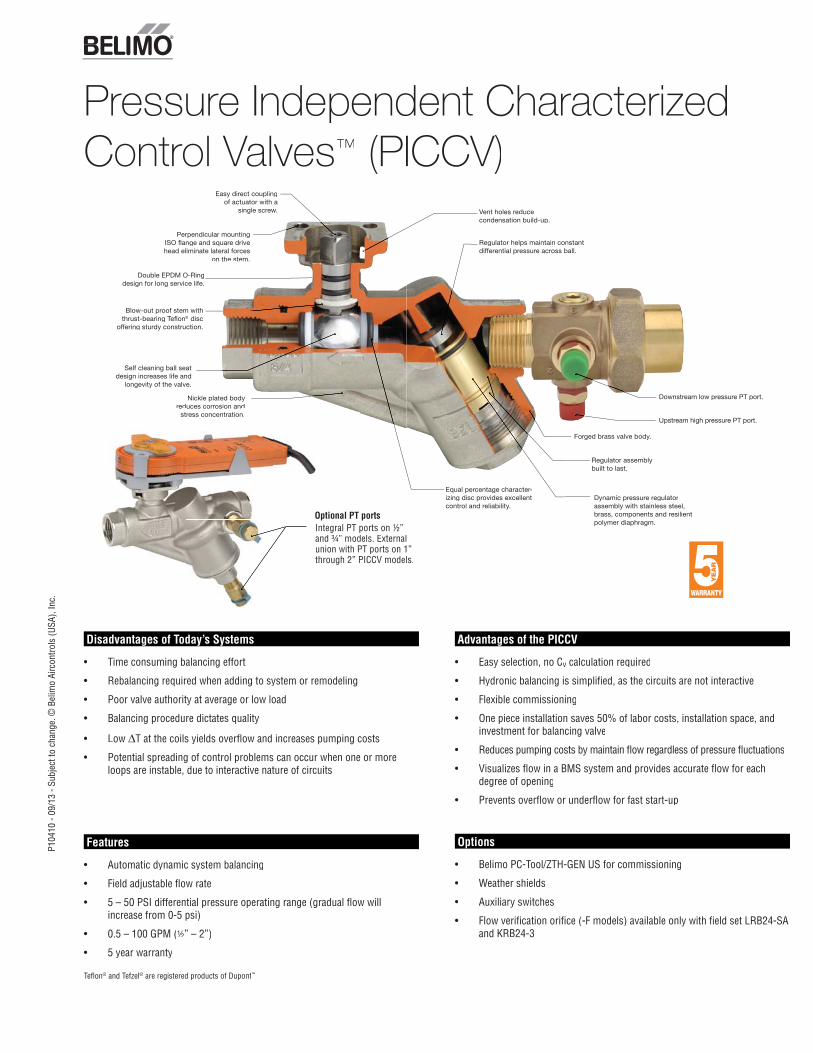
Pressure Independent CharacterizedControl Valves™ (PICCV)
Integral PT ports on ½”Iand ¾” models. Externalaunion with PT ports on 1”uthrough 2” PICCV models.t
Optional PT portsO
Features
• Automatic dynamic system balancing
• Field adjustable fl ow rate
• 5 – 50 PSI differential pressure operating range (gradual fl ow will increase from 0-5 psi)
• 0.5 – 100 GPM (½” – 2”)
• 5 year warranty
Tefl on® and Tefzel® are registered products of Dupont™
Perpendicular mountingISO fl ange and square drivehead eliminate lateral forces
on the stem.
Easy direct coupling of actuator with a
single screw.
Blow-out proof stem withthrust-bearing Tefl on® disc
offering sturdy construction.
Self cleaning ball seatdesign increases life and
longevity of the valve.
Vent holes reducecondensation build-up.
Equal percentage character-izing disc provides excellentcontrol and reliability.
Forged brass valve body.
Dynamic pressure regulatorassembly with stainless steel,brass, components and resilientpolymer diaphragm.
Downstream low pressure PT port.
Upstream high pressure PT port.
Double EPDM O-Ring design for long service life.
Nickle plated body reduces corrosion and
stress concentration.
Regulator helps maintain constantdifferential pressure across ball.
Regulator assemblybuilt to last.
800-543-9038 USA 866-805-7089 CANADA 203-791-8396 LATIN AMERICA / CARIBBEAN
2
P104
10 -
09/1
3 - S
ubje
ct to
cha
nge.
© B
elim
o Ai
rcon
trols
(USA
), In
c.
Set-upPressure Independent Characterized Control Valves (PICCV)
INSTALLATIONPICCVs should be installed with fl ow in the direction of the arrowon the valve body. If installed backwards, there could be damage da ageto either the diaphragm or the regulator.
The valve assembly can be installed in a vertical or horizontal arrangement, as long as the actuator is positioned to avoid condensation from dripping on the actuator.
SET-UP
2-WAY VALVESPECIFY UPON ORDERING
NON-
SPRI
NG R
ETUR
NSt
ays
in L
ast P
ositi
on
LRB24-3, KRB24-3 Floating type actuators
NC: Normally Closed-Factory default with the directional switch in the 1 positon. Power to pin2 will drive valve CW. Power to pin 3 will drive valve CCW.
NO: Normally Open- LRB Only- Changedirectional switch from default “1” position to the“0” postion.
LRX24-MFTARX24-MFT MFT type actuators*
NC: Normally Closed-valve will open as voltageincreases.Actuator switch on Y2.
NO: Normally Open-valve will close as voltageincreases.Actuator switch on Y1.
LRB24-SA NC ONLY: NormallyClosed-valve will open asvoltage increases.Actuator switch on Y2
SPRI
NG R
ETUR
NNo
te F
ail P
ositi
on
LF24-MFT USAFRX24-MFTMFT type actuators†
NC/FO Valve: NormallyClosed-valve will open as voltage increases. Actuator switch on CW.Spring Action: Will fail open upon power loss.
NC/FC Valve: NormallyClosed-valve will openas voltage increases. Actuator switch on CW.Spring Action: Will fail closed upon power loss.
NO/FC Valve: NormallyOpen-valve will closeas voltage increases. Actuator switch on CCW.Spring Action: Will fail closed upon power loss.
NO/FO Valve: NormallyOpen-valve will closeas voltage increases. Actuator switch on CCW.Spring Action: Will fail open upon power loss.
TFRX24-MFT NC/FO Valve: NormallyClosed-valve will open asvoltage increases.Switch on (arrow setting)Spring Action: Will fail open upon power loss.
NC/FC Valve: NormallyClosed-valve will open asvoltage increases.Switch on (arrow setting)Spring Action: Will fail closed upon power loss.
NO/FC Valve: NormallyOpen-valve will close asvoltage increases.Switch on (arrow setting)Spring Action: Will fail closed upon power loss.
NO/FO Valve: NormallyOpen-valve will close asvoltage increases. Switch on (arrow setting)Spring Action: Will fail open upon power loss.
*The design fl ow rate of PICCVs with MFT actuators are dependent on their Minimum and Maximum Percentages of rotation. Actuators must be re-programmed for different Minimum and Maximum Settings if actuator set-ups must be changed. Please refer to PICCV online technical documentation, MFT Adjustment Tables, for re-programming the settings.
800-543-9038 USA 866-805-7089 CANADA 203-791-8396 LATIN AMERICA / CARIBBEAN
3
P104
10 -
09/1
3 - S
ubje
ct to
cha
nge.
© B
elim
o Ai
rcon
trols
(USA
), In
c.
Operation / InstallationPressure Independent Characterized Control Valves (PICCV)
Maintain design fl ow independent of pressure variations.The PICCV is a two-way valve that will supply a specific flow for each degree of ball opening regardless of pressure variations in a system.
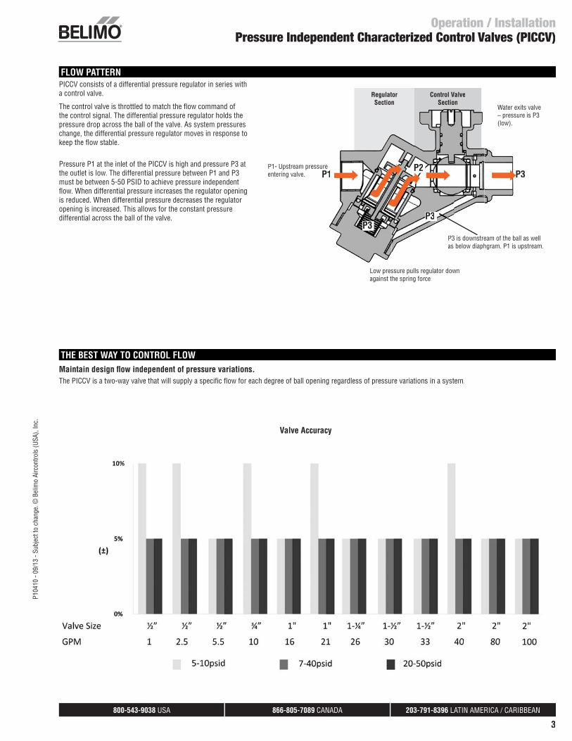
FLOW PATTERNPICCV consists of a differential pressure regulator in series witha control valve.
The control valve is throttled to match the fl ow command of the control signal. The differential pressure regulator holds the pressure drop across the ball of the valve. As system pressureschange, the differential pressure regulator moves in response to keep the fl ow stable.
Pressure P1 at the inlet of the PICCV is high and pressure P3 at the outlet is low. The differential pressure between P1 and P3 must be between 5-50 PSID to achieve pressure independent fl ow. When differential pressure increases the regulator opening is reduced. When differential pressure decreases the regulatoropening is increased. This allows for the constant pressure differential across the ball of the valve.
RegulatorSection
Control ValveSection
Water exits valve – pressure is P3(low).
Low pressure pulls regulator downagainst the spring force.
P1- Upstream pressureentering valve. P1 P3
P3P3 is downstream of the ball as wellas below diaphgram. P1 is upstream.
P3
THE BEST WAY TO CONTROL FLOW
P2
Valve Accuracy
800-543-9038 USA 866-805-7089 CANADA 203-791-8396 LATIN AMERICA / CARIBBEAN
4
P104
10 -
09/1
3 - S
ubje
ct to
cha
nge.
© B
elim
o Ai
rcon
trols
(USA
), In
c.
TYPICAL PARALLEL PIPING IN RELATION TO THE INPUT AND OUTPUT (SCALE: NONE)
BELIMO PICCV (TYP.)
UNION CONNECTION (TYP.)
PT PORTPT PORT
AIR VENT
H/C–COIL
PT PORT
PT PORT
PT PORT
FLOWTEE (TYP.)
SHUT–OFFVALVE
SHUT–OFFVALVE
PARALLEL PIPING ARRANGEMENT FOR PICCV
FLOW
FLOW
FLOW
FLOWSTRAINERFLOWPT PORT
DRAIN
FLOW
TYPICAL PARALLEL PIPING IN RELATION
TO THE INPUT AND OUTPUT
(Optional)
TYPICAL PIPING IN RELATION TO THE INPUT AND OUTPUT (SCALE: NONE)
FLOW
TYPICAL PARALLEL PIPING IN RELATION
TO THE INPUT AND OUTPUT
H/C–COIL
AIR VENT
PT PORT PT PORT
BELIMO PICCV (TYP.)
FLOW
SHUT–OFFVALVE
FLOW
DRAIN
PT PORT FLOW FLOWSTRAINER SHUT–OFFVALVE
UNION CONNECTION (TYP.)
(Optional)
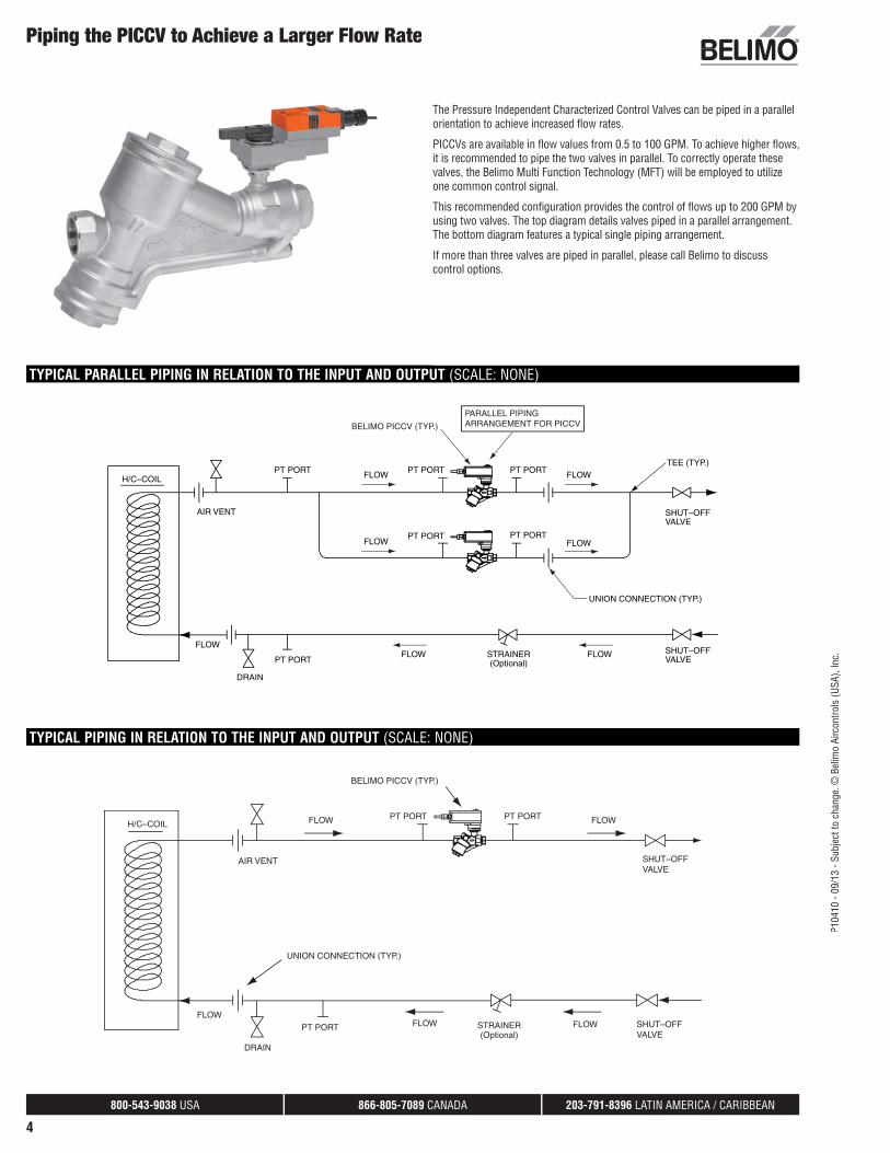
Piping the PICCV to Achieve a Larger Flow Rate
The Pressure Independent Characterized Control Valves can be piped in a parallel orientation to achieve increased fl ow rates.
PICCVs are available in fl ow values from 0.5 to 100 GPM. To achieve higher fl ows, it is recommended to pipe the two valves in parallel. To correctly operate these valves, the Belimo Multi Function Technology (MFT) will be employed to utilizeone common control signal.
This recommended confi guration provides the control of fl ows up to 200 GPM by using two valves. The top diagram details valves piped in a parallel arrangement.The bottom diagram features a typical single piping arrangement.
If more than three valves are piped in parallel, please call Belimo to discusscontrol options.
800-543-9038 USA 866-805-7089 CANADA 203-791-8396 LATIN AMERICA / CARIBBEAN
5
P104
10 -
09/1
3 - S
ubje
ct to
cha
nge.
© B
elim
o Ai
rcon
trols
(USA
), In
c.Nomenclature
Pressure Independent Characterized Control Valves (PICCV)
Ordering Example
2
1 Choose the valve actuator combination.
Specify preference or confi guration.Does order
require
tagging?
4
For MFT Orders Only - Select Programming Code
Non-Spring Return Actuator Models
NO = Normally Open
NC = Normally Closed
Spring Return Actuator Models
NO/FO = Normally Open/Fail Open
NO/FC = Normally Open/Fail Closed
NC/FO = Normally Closed/Fail Open
NC/FC = Normally Closed/Fail Closed
Refers to valve ports from inlet to outlet, per fl ow
arrow.
Set-Up
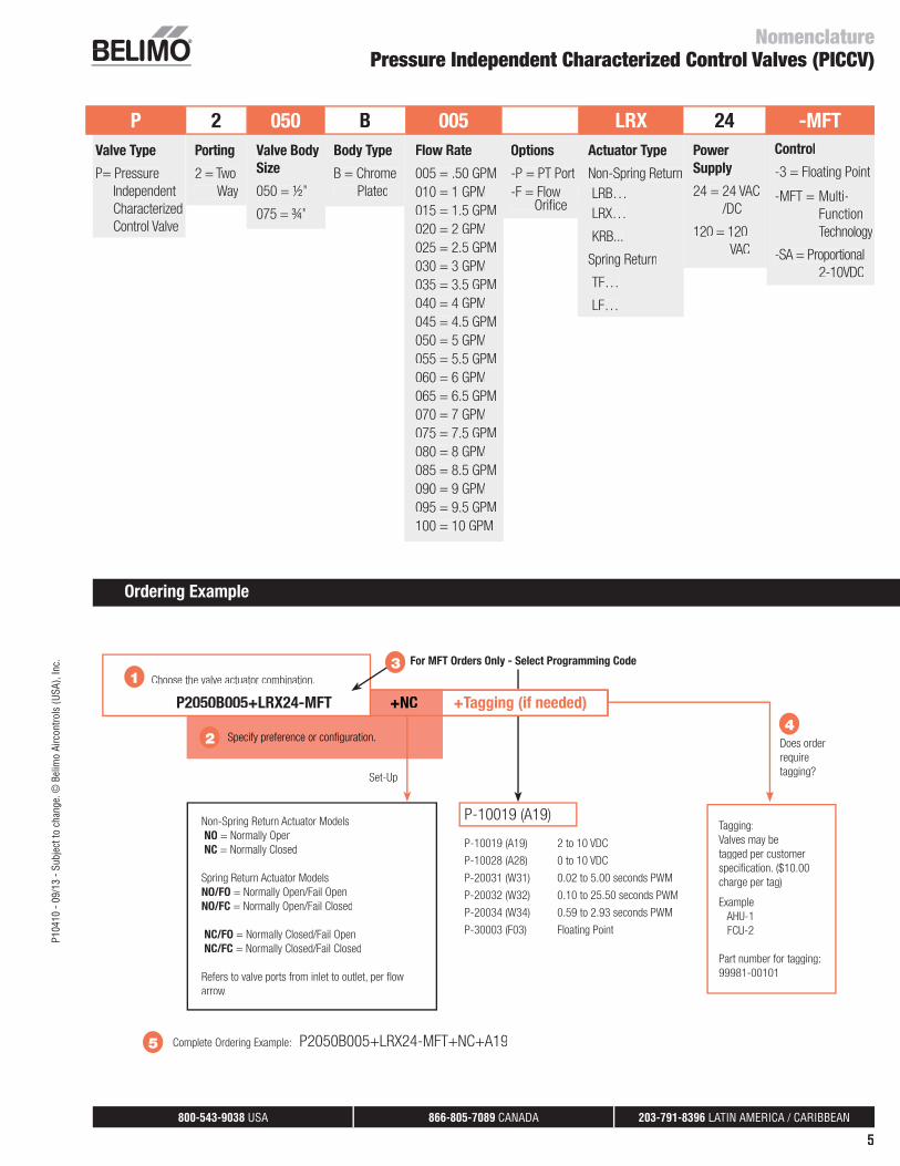
5 Complete Ordering Example: P2050B005+LRX24-MFT+NC+A19
P-10019 (A19)
P-10019 (A19) 2 to 10 VDC
P-10028 (A28) 0 to 10 VDC
P-20031 (W31) 0.02 to 5.00 seconds PWM
P-20032 (W32) 0.10 to 25.50 seconds PWM
P-20034 (W34) 0.59 to 2.93 seconds PWM
P-30003 (F03) Floating Point
3
Tagging:
Valves may be
tagged per customer
specifi cation. ($10.00
charge per tag)
Example:
AHU-1
FCU-2
Part number for tagging:
99981-00101
+NC P2050B005+LRX24-MFT +Tagging (if needed)
P 2 050 B 005 LRX 24 -MFT
Valve Type
P= Pressure
Independent
Characterized
Control Valve
Porting
2 = Two
Way
Valve Body
Size
050 = ½”
075 = ¾”
Body Type
B = Chrome
Plated
Flow Rate
005 = .50 GPM
010 = 1 GPM
015 = 1.5 GPM
020 = 2 GPM
025 = 2.5 GPM
030 = 3 GPM
035 = 3.5 GPM
040 = 4 GPM
045 = 4.5 GPM
050 = 5 GPM
055 = 5.5 GPM
060 = 6 GPM
065 = 6.5 GPM
070 = 7 GPM
075 = 7.5 GPM
080 = 8 GPM
085 = 8.5 GPM
090 = 9 GPM
095 = 9.5 GPM
100 = 10 GPM
Options
-P = PT Port
-F = Flow Orifi ce
Actuator Type
Non-Spring Return
LRB…
LRX…
KRB...
Spring Return
TF…
LF…
Power
Supply
24 = 24 VAC
/DC
120 = 120
VAC
Control
-3 = Floating Point
-MFT = Multi-
Function
Technology
-SA = Proportional
2-10VDC
800-543-9038 USA 866-805-7089 CANADA 203-791-8396 LATIN AMERICA / CARIBBEAN
6
P104
10 -
09/1
3 - S
ubje
ct to
cha
nge.
© B
elim
o Ai
rcon
trols
(USA
), In
c.
NomenclaturePressure Independent Characterized Control Valves (PICCV)
Ordering Example
2
1 Choose the valve actuator combination.
+NC PICCV-25-012+LRX24-MFT +Tagging (if needed)
Specify preference or confi guration.Does order
require
tagging?
4
For MFT orders only - select programming code
Non-Spring Models
NO = Normally Open
NC = Normally Closed
Spring Return Models
NO/FO = Normally Open/Fail Open
NO/FC = Normally Open/Fail Closed
NC/FO = Normally Closed/Fail Open
NC/FC = Normally Closed/Fail Closed
Refers to valve ports from inlet to outlet, per fl ow
arrow.
Set-Up
5 Complete Ordering Example: PICCV-25-012+LRX24-MFT+NC+A19
P-10019 (A19)
P-10019 (A19) 2 to 10 VDC
P-10028 (A28) 0 to 10 VDC
P-20031 (W31) 0.02 to 5.00 seconds PWM
P-20032 (W32) 0.10 to 25.50 seconds PWM
P-20034 (W34) 0.59 to 2.93 seconds PWM
P-30003 (F03) Floating Point
P-10019 (A19) On/Off**
3
** Wire for On/Off
Tagging:
Valves may be
tagged per customer
specifi cation. ($10.00
charge per tag)
Example:
AHU-1
FCU-2
Part number for tagging:
99981-00101
PICCV 25 -012 +LRX 24 -MFT
PressureIndependent Characterized Control Valve
2-way Chrome
Plated Brass Ball
and Brass Stem
Valve Size
25 = 1”
32 = 1¼”
40 = 1½”
50 = 2”
Flow Rate
3 GPM
Refer to table
Options
-P = PT Port
-F = Flow Orifi ce
Actuator Type
Non-Spring Return
LRB…
LRX…
ARX…
Spring Return
TF…
LF…
AF…
Power Supply
24 = 24 VAC/DC
120 = 120 VAC
Control
-3 = Floating Point
-MFT = Multi-Function
Technology
-SA = Proportional
2-10 VDC
S = Built-in
Auxiliary
Switch
800-543-9038 USA 866-805-7089 CANADA 203-791-8396 LATIN AMERICA / CARIBBEAN
7
P104
10 -
09/1
3 - S
ubje
ct to
cha
nge.
© B
elim
o Ai
rcon
trols
(USA
), In
c.
Factory Set Pressure Independent Characterized Control Valves (PICCV)Product Range Overview – P2..., 2-way
PICCV
Characteristic
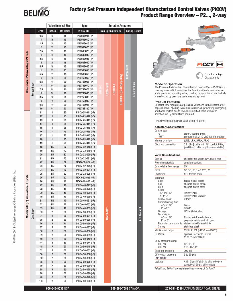
Mode of OperationThe Pressure Independent Characterized Control Valve (PICCV) is atwo-way valve which combines the functionality of a control valveand a pressure regulating valve, creating one precise product whichis unaffected by pressure variations in a system.
Product FeaturesConstant fl ow regardless of pressure variations in the system at setdegrees of ball opening. Maximizes chiller ΔT, preventing energizing additional chillers due to low ΔT. Simplifi ed valve sizing and selection, no Cv calculations required.
(-P) ΔP verifi cation across valve using PT ports.
Actuator Specifi cationsControl type -3 on/off, fl oating point -MFT proportional, 2-10 VDC (confi gurable)Manual override (LRB, LRX, AFRX, ARX)Electrical connection 3 ft. [1m] cable with ½” conduit fi tting (additional cable lengths are available)
Valve Specifi cationsService chilled or hot water, 60% glycol maxFlow characteristic equal percentageControllable fl ow range 75°Sizes ½”, ¾”, 1”, 1¼”, 1½”, 2”End fi tting NPT female endsMaterials Body brass, nickel plated Ball chrome plated brass Stem chrome plated brass Seats ½” and ¾” Tefl on® PTFE 1” to 2” Tefl on® PTFE /Tefzel® Seat o-rings Viton® Characterizing disc ½” and ¾” brass 1” to 2” Tefzel® O-rings EPDM (lubricated) Diaphragm ½” and ¾” Nomex reinforced silicone 1” to 2” polyester reinforced silicone Regulator components stainless steel/brass/Nitrile Spring stainless steelMedia temp range 0°F to 212°F [-18°C to +100°C]PT Ports optional, ½” to ¾” internal 1” to 2” external (-P)Body pressure rating 600 psi ½”, ¾”, 1” 400 psi 1¼”, 1½”, 2” Close off pressure 200 psi Differential pressure 5 to 50 psid(ΔP) rangeLeakage ANSI Class IV (0.01% of rated valve capacity at 50 psi differential)Tefzel® and Tefl on® are registered trademarks of DuPont™
Valve Nominal Size Type Suitable Actuators
GPM** Inches DN [mm] 2-way NPT Non-Spring Return Spring ReturnM
odel
s w
ith (-
P) h
ave
inte
gral
PT
ports
Forg
ed B
ody
0.5 ½ 15 P2050B005 (-P)
LRB2
4-3
LRX2
4-M
FT
LRX1
20-3
LRCB
24-3
(Hea
t Pum
p On
ly)
TFRX
24-M
FT
LF24
-MFT
US
1 ½ 15 P2050B010 (-P)1.5 ½ 15 P2050B015 (-P)2 ½ 15 P2050B020 (-P)
2.5 ½ 15 P2050B025 (-P)3 ½ 15 P2050B030 (-P)
3.5 ½ 15 P2050B035 (-P)4 ½ 15 P2050B040 (-P)
4.5 ½ 15 P2050B045 (-P)5 ½ 15 P2050B050 (-P)
5.5 ½ 15 P2050B055 (-P)6 ¾ 20 P2075B060 (-P)
6.5 ¾ 20 P2075B065 (-P)7 ¾ 20 P2075B070 (-P)
7.5 ¾ 20 P2075B075 (-P)8 ¾ 20 P2075B080 (-P)
8.5 ¾ 20 P2075B085 (-P)9 ¾ 20 P2075B090 (-P)
9.5 ¾ 20 P2075B095 (-P)10 ¾ 20 P2075B100 (-P)
Mod
els
with
(-P)
hav
e ex
tern
al P
T po
rts
11 1 25 PICCV-25-011 (-P)12 1 25 PICCV-25-012 (-P)13 1 25 PICCV-25-013 (-P)14 1 25 PICCV-25-014 (-P)15 1 25 PICCV-25-015 (-P)16 1 25 PICCV-25-016 (-P)17 1 25 PICCV-25-017 (-P)18 1 25 PICCV-25-018 (-P)19 1 25 PICCV-25-019 (-P)
Cast
Bod
y
18 1¼ 32 PICCV-32-018 (-P)
ARX2
4-M
FT
AFRX
24-M
FT
19 1¼ 32 PICCV-32-019 (-P)20 1¼ 32 PICCV-32-020 (-P)21 1¼ 32 PICCV-32-021 (-P)22 1¼ 32 PICCV-32-022 (-P)23 1¼ 32 PICCV-32-023 (-P)24 1¼ 32 PICCV-32-024 (-P)25 1¼ 32 PICCV-32-025 (-P)26 1¼ 32 PICCV-32-026 (-P)26 1½ 40 PICCV-40-026 (-P)27 1½ 40 PICCV-40-027 (-P)28 1½ 40 PICCV-40-028 (-P)29 1½ 40 PICCV-40-029 (-P)30 1½ 40 PICCV-40-030 (-P)31 1½ 40 PICCV-40-031 (-P)32 1½ 40 PICCV-40-032 (-P)33 1½ 40 PICCV-40-033 (-P)33 2 50 PICCV-50-033 (-P)34 2 50 PICCV-50-034 (-P)35 2 50 PICCV-50-035 (-P)36 2 50 PICCV-50-036 (-P)37 2 50 PICCV-40-037 (-P)38 2 50 PICCV-40-038 (-P)39 2 50 PICCV-40-039 (-P)40 2 50 PICCV-50-040 (-P)44 2 50 PICCV-50-044 (-P)48 2 50 PICCV-50-048 (-P)52 2 50 PICCV-50-052 (-P)56 2 50 PICCV-50-056 (-P)60 2 50 PICCV-50-060 (-P)65 2 50 PICCV-50-065 (-P)70 2 50 PICCV-50-070 (-P)75 2 50 PICCV-50-075 (-P)80 2 50 PICCV-50-080 (-P)90 2 50 PICCV-50-090 (-P)
100 2 50 PICCV-50-100 (-P)
800-543-9038 USA 866-805-7089 CANADA 203-791-8396 LATIN AMERICA / CARIBBEAN
8
P104
10 -
09/1
3 - S
ubje
ct to
cha
nge.
© B
elim
o Ai
rcon
trols
(USA
), In
c.
Field SetPressure Independent Characterized Control Valves (PICCV)Product Range Overview – P2..., 2-way
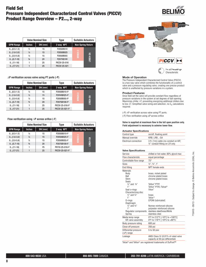
Mode of OperationThe Pressure Independent Characterized Control Valve (PICCV)is a two-way valve which combines the functionality of a controlvalve and a pressure regulating valve, creating one precise productwhich is unaffected by pressure variations in a system.
Product FeaturesOnce fi eld set the valve will provide constant fl ow regardless ofpressure variations in the system at set degrees of ball opening.Maximizes chiller ΔT, preventing energizing additional chillers due to low ΔT. Simplifi ed valve sizing and selection, no Cv calculationsrequired.
(-P) ΔP verifi cation across valve using PT ports.(-F) Flow verifi cation using ΔP across orifi ce.
Valve is supplied at maximum fl ow in the full open position only.Field adjustment is necessary to acheive lower fl ow.
Actuator Specifi cationsControl type on/off, fl oating pointManual override KRB, LRB...-SAElectrical connection 3 ft. [1m] cable (no conduit on KR) ½” conduit fi tting on LR only
Valve Specifi cationsService chilled or hot water, 60% glycol maxFlow characteristic equal percentageControllable fl ow range 75°Sizes ½”, ¾”, 1”End fi tting NPT female endsMaterials Body brass, nickel plated Ball chrome plated brass Stem chrome plated brass Seats ½” and ¾” Tefl on® PTFE 1” Tefl on® PTFE /Tefzel® Seat o-rings Viton® Characterizing disc ½” and ¾” brass 1” Tefzel® O-rings EPDM (lubricated) Diaphragm ½” and ¾” Nomex reinforced silicone 1” polyester reinforced silicone Regulator components stainless steel/brass/Nitrile Spring stainless steelMedia temp range 0°F to 212°F [-18°C to +100°C] KR valve assembly 0°F to 176°F [-18°C to +80°C]Body pressure rating 600 psiClose off pressure 200 psi Differential pressure 5 to 50 psid(ΔP) rangeLeakage ANSI Class IV (0.01% of rated valve capacity at 50 psi differential)Tefzel® and Tefl on® are registered trademarks of DuPont™
Valve Nominal Size Type Suitable Actuators
GPM Range Inches DN [mm] 2-way NPT Non-Spring Return
0...(0.5-1.5) ½ 15 P2050B010
KRB2
4-3
LRB2
4-SA
0...(1.6-3.0) ½ 15 P2050B0250...(3.0-5.6) ½ 15 P2050B0550...(5.7-10) ¾ 20 P2075B1000...(11-16) 1 25 PICCV-25-0160...(17-21) 1 25 PICCV-25-021
PICCV
Characteristic
ΔP verifi cation across valve using PT ports (-P)
Valve Nominal Size Type Suitable Actuators
GPM Range Inches DN [mm] 2-way NPT Non-Spring Return
0...(0.5-1.5) ½ 15 P2050B010-P
KRB2
4-3
LRB2
4-SA
0...(1.6-3.0) ½ 15 P2050B025-P0...(3.0-5.6) ½ 15 P2050B055-P0...(5.7-10) ¾ 20 P2075B100-P0...(11-16) 1 25 PICCV-25-016-P0...(17-21) 1 25 PICCV-25-021-P
Flow verifi cation using ΔP across orifi ce (-F)
Valve Nominal Size Type Suitable Actuators
GPM Range Inches DN [mm] 2-way NPT Non-Spring Return
0...(0.5-1.5) ½ 15 P2050B010-F
KRB2
4-3
LRB2
4-SA
0...(1.6-3.0) ½ 15 P2050B025-F0...(3.0-5.6) ½ 15 P2050B055-F0...(5.7-10) ¾ 20 P2075B100-F0...(11-16) 1 25 PICCV-25-016-F0...(17-21) 1 25 PICCV-25-021-F
800-543-9038 USA 866-805-7089 CANADA 203-791-8396 LATIN AMERICA / CARIBBEAN
9
P104
10 -
09/1
3 - S
ubje
ct to
cha
nge.
© B
elim
o Ai
rcon
trols
(USA
), In
c.Factory Set
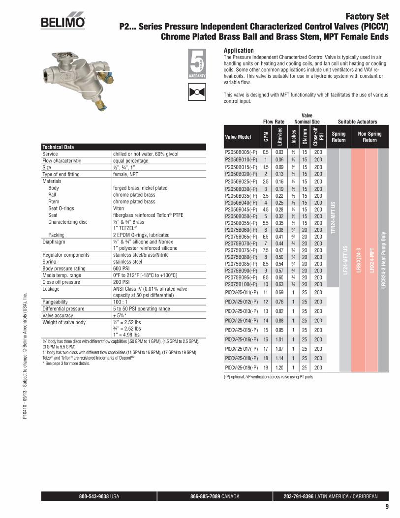
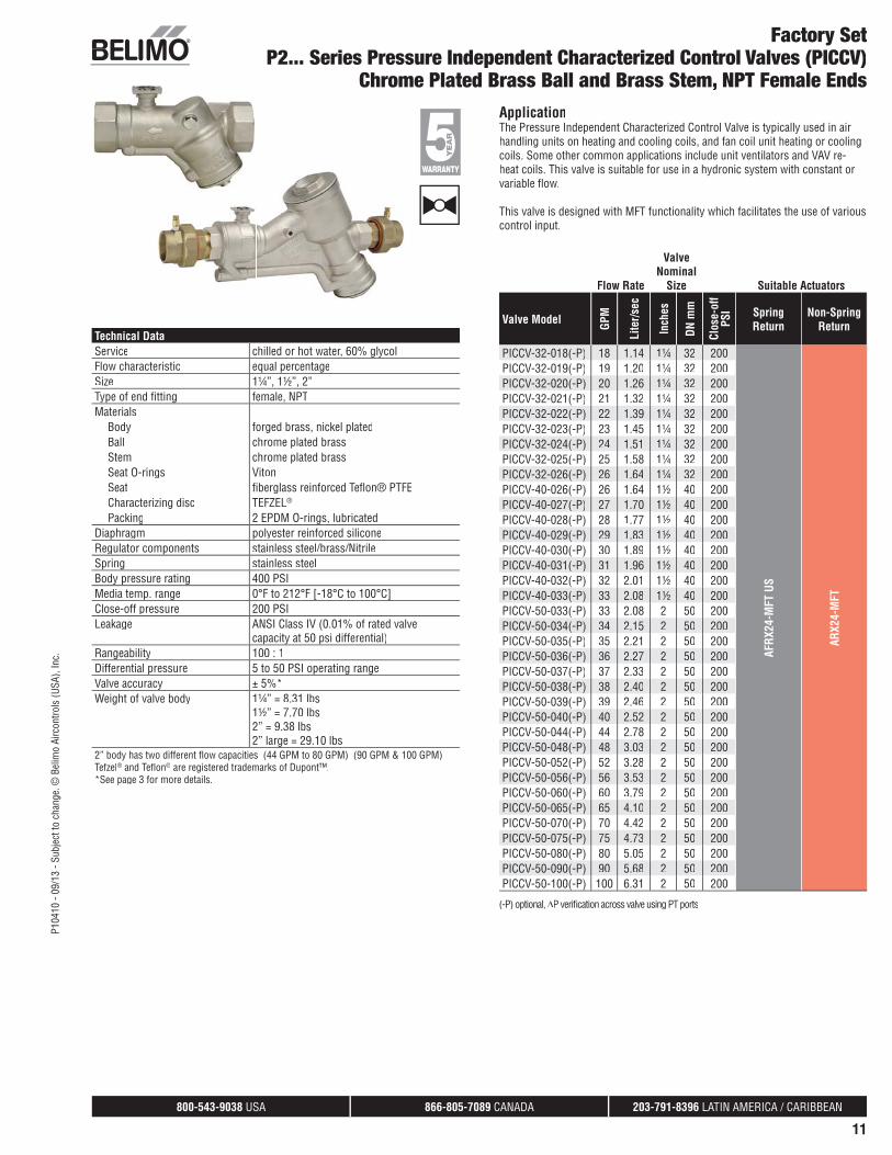
P2... Series Pressure Independent Characterized Control Valves (PICCV)Chrome Plated Brass Ball and Brass Stem, NPT Female Ends
Technical DataService chilled or hot water, 60% glycolFlow characteristic equal percentageSize ½”, ¾”, 1”Type of end fi tting female, NPTMaterials
Body forged brass, nickel platedBall chrome plated brassStem chrome plated brassSeat O-rings VitonSeat fi berglass reinforced Tefl on® PTFECharacterizing disc ½” & ¾” Brass
1” TEFZEL®
Packing 2 EPDM O-rings, lubricatedDiaphragm ½” & ¾” silicone and Nomex
1” polyester reinforced siliconeRegulator components stainless steel/brass/NitrileSpring stainless steelBody pressure rating 600 PSIMedia temp. range 0°F to 212°F [-18°C to +100°C]Close off pressure 200 PSILeakage ANSI Class IV (0.01% of rated valve
capacity at 50 psi differential)Rangeability 100 : 1Differential pressure 5 to 50 PSI operating rangeValve accuracy ± 5%*Weight of valve body ½” = 2.52 lbs
¾” = 2.52 lbs1” = 4.98 lbs
½” body has three discs with different fl ow capbilities (.50 GPM to 1 GPM), (1.5 GPM to 2.5 GPM),(3 GPM to 5.5 GPM) 1” body has two discs with different fl ow capabilities (11 GPM to 16 GPM), (17 GPM to 19 GPM) Tefzel® and Tefl on® ® are registered trademarks of Dupont™®
* See page 3 for more details.
ApplicationThe Pressure Independent Characterized Control Valve is typically used in airhandling units on heating and cooling coils, and fan coil unit heating or cooling coils. Some other common applications include unit ventilators and VAV re-heat coils. This valve is suitable for use in a hydronic system with constant or variable fl ow.
This valve is designed with MFT functionality which facilitates the use of variouscontrol input.
Flow RateValve
Nominal Size Suitable Actuators
Valve Model GPM
Lite
r/sec
Inch
es
DN m
m
Clos
e-of
f PS
I Spring Return
Non-Spring Return
P2050B005(-P) 0.5 0.03 ½ 15 200
TFR2
4-M
FT U
S
LF24
-MFT
US
LRB(
X)24
-3
LRX2
4-M
FT
LRCB
24-3
Hea
t Pum
p On
ly
P2050B010(-P) 1 0.06 ½ 15 200P2050B015(-P) 1.5 0.09 ½ 15 200P2050B020(-P) 2 0.13 ½ 15 200P2050B025(-P) 2.5 0.16 ½ 15 200P2050B030(-P) 3 0.19 ½ 15 200P2050B035(-P) 3.5 0.22 ½ 15 200P2050B040(-P) 4 0.25 ½ 15 200P2050B045(-P) 4.5 0.28 ½ 15 200P2050B050(-P) 5 0.32 ½ 15 200P2050B055(-P) 5.5 0.35 ½ 15 200P2075B060(-P) 6 0.38 ¾ 20 200P2075B065(-P) 6.5 0.41 ¾ 20 200P2075B070(-P) 7 0.44 ¾ 20 200P2075B075(-P) 7.5 0.47 ¾ 20 200P2075B080(-P) 8 0.50 ¾ 20 200P2075B085(-P) 8.5 0.54 ¾ 20 200P2075B090(-P) 9 0.57 ¾ 20 200P2075B095(-P) 9.5 0.60 ¾ 20 200P2075B100(-P) 10 0.63 ¾ 20 200PICCV-25-011(-P) 11 0.69 1 25 200
PICCV-25-012(-P) 12 0.76 1 25 200
PICCV-25-013(-P) 13 0.82 1 25 200
PICCV-25-014(-P) 14 0.88 1 25 200
PICCV-25-015(-P) 15 0.95 1 25 200
PICCV-25-016(-P) 16 1.01 1 25 200
PICCV-25-017(-P) 17 1.07 1 25 200
PICCV-25-018(-P) 18 1.14 1 25 200
PICCV-25-019(-P) 19 1.20 1 25 200
(-P) optional, ΔP verifi cation across valve using PT ports
800-543-9038 USA 866-805-7089 CANADA 203-791-8396 LATIN AMERICA / CARIBBEAN
10
P104
10 -
09/1
3 - S
ubje
ct to
cha
nge.
© B
elim
o Ai
rcon
trols
(USA
), In
c.
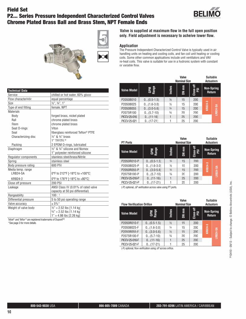
Field SetP2... Series Pressure Independent Characterized Control ValvesChrome Plated Brass Ball and Brass Stem, NPT Female Ends
Technical DataService chilled or hot water, 60% glycolFlow characteristic equal percentageSize ½”, ¾”, 1”Type of end fi tting female, NPTMaterials
Body forged brass, nickel platedBall chrome plated brassStem chrome plated brassSeat O-rings VitonSeat fi berglass reinforced Tefl on® PTFECharacterizing disc ½” & ¾” brass
1” TEFZEL®
Packing 2 EPDM O-rings, lubricatedDiaphragm ½” & ¾” silicone and Nomex
1” polyester reinforced siliconeRegulator components stainless steel/brass/NitrileSpring stainless steelBody pressure rating 600 PSIMedia temp. range LRB24-SA 0°F to 212°F [-18°C to +100°C]
KRB24-3 0°F to 176°F [-18°C to +80°C]Close off pressure 200 PSILeakage ANSI Class IV (0.01% of rated valve
capacity at 50 psi differential)Rangeability 100 : 1Differential pressure 5 to 50 psi operating rangeValve accuracy ± 5%*Weight of valve body ½” = 2.52 lbs [1.14 kg]
¾” = 2.52 lbs [1.14 kg]1” = 4.98 lbs [2.26 kg]
Tefzel® and Tefl on® ® are registered trademarks of Dupont™.®
*See page 3 for more details.
Valve is supplied at maximum fl ow in the full open positiononly. Field adjustment is necessary to acheive lower fl ow.
ApplicationThe Pressure Independent Characterized Control Valve is typically used in airhandling units on heating and cooling coils, and fan coil unit heating or cooling coils. Some other common applications include unit ventilators and VAVre-heat coils. This valve is suitable for use in a hydronic system with constantor variable fl ow.
ValveNominal Size
Suitable Actuators
Valve Model GPM
Ra
nge
Inch
es
DN m
m
Clos
e-of
f PS
I Non-Spring Return
P2050B010 0...(0.5-1.5) ½ 15 200
KRB2
4-3
LRB2
4-SA
P2050B025 0...(1.6-3.0) ½ 15 200P2050B055 0...(3.0-5.6) ½ 15 200P2075B100 0...(5.7-10) ¾ 20 200PICCV-25-016 0...(11-16) 1 25 200PICCV-25-021 0...(17-21) 1 25 200
PT PortsValve
Nominal SizeSuitable Actuators
Valve Model GPM
Ra
nge
Inch
es
DN m
m
Clos
e-of
f PS
I Non-Spring Return
P2050B010-P 0...(0.5-1.5) ½ 15 200
KRB2
4-3
LRB2
4-SA
P2050B025-P 0...(1.6-3.0) ½ 15 200P2050B055-P 0...(3.0-5.6) ½ 15 200P2075B100-P 0...(5.7-10) ¾ 20 200PICCV-25-016-P 0...(11-16) 1 25 200PICCV-25-021-P 0...(17-21) 1 25 200(-P) optional, ΔP verifi cation across valve using PT ports.
Flow Verifi cation Orifi ceValve
Nominal SizeSuitable Actuators
Valve Model GPM
Ra
nge
Inch
es
DN m
m
Clos
e-of
f PS
I Non-Spring Return
P2050B010-F 0...(0.5-1.5) ½ 15 200
KRB2
4-3
LRB2
4-SA
P2050B025-F 0...(1.6-3.0) ½ 15 200P2050B055-F 0...(3.0-5.6) ½ 15 200P2075B100-F 0...(5.7-10) ¾ 20 200PICCV-25-016-F 0...(11-16) 1 25 200PICCV-25-021-F 0...(17-21) 1 25 200(-F) optional, fl ow verifi cation using ΔP across orifi ce.
800-543-9038 USA 866-805-7089 CANADA 203-791-8396 LATIN AMERICA / CARIBBEAN
11
P104
10 -
09/1
3 - S
ubje
ct to
cha
nge.
© B
elim
o Ai
rcon
trols
(USA
), In
c.
Factory SetP2... Series Pressure Independent Characterized Control Valves (PICCV)
Chrome Plated Brass Ball and Brass Stem, NPT Female Ends
Technical DataService chilled or hot water, 60% glycolFlow characteristic equal percentageSize 1¼”, 1½”, 2”Type of end fi tting female, NPTMaterials
Body forged brass, nickel platedBall chrome plated brassStem chrome plated brassSeat O-rings VitonSeat fi berglass reinforced Tefl on® PTFECharacterizing disc TEFZEL®
Packing 2 EPDM O-rings, lubricatedDiaphragm polyester reinforced siliconeRegulator components stainless steel/brass/NitrileSpring stainless steelBody pressure rating 400 PSIMedia temp. range 0°F to 212°F [-18°C to 100°C]Close-off pressure 200 PSILeakage ANSI Class IV (0.01% of rated valve
capacity at 50 psi differential)Rangeability 100 : 1Differential pressure 5 to 50 PSI operating rangeValve accuracy ± 5%*Weight of valve body 1¼” = 8.31 lbs
1½” = 7.70 lbs2” = 9.38 lbs2” large = 29.10 lbs
2” body has two different fl ow capacities (44 GPM to 80 GPM) (90 GPM & 100 GPM)Tefzel® and Tefl on® are registered trademarks of Dupont™.*See page 3 for more details.
ApplicationThe Pressure Independent Characterized Control Valve is typically used in airhandling units on heating and cooling coils, and fan coil unit heating or cooling coils. Some other common applications include unit ventilators and VAV re-heat coils. This valve is suitable for use in a hydronic system with constant orvariable fl ow.
This valve is designed with MFT functionality which facilitates the use of variouscontrol input.
Flow Rate
ValveNominal
Size Suitable Actuators
Valve Model GPM
Lite
r/sec
Inch
es
DN m
m
Clos
e-of
f PS
I Spring Return
Non-Spring Return
PICCV-32-018(-P) 18 1.14 1¼ 32 200
AFRX
24-M
FT U
S
ARX2
4-M
FT
PICCV-32-019(-P) 19 1.20 1¼ 32 200PICCV-32-020(-P) 20 1.26 1¼ 32 200PICCV-32-021(-P) 21 1.32 1¼ 32 200PICCV-32-022(-P) 22 1.39 1¼ 32 200PICCV-32-023(-P) 23 1.45 1¼ 32 200PICCV-32-024(-P) 24 1.51 1¼ 32 200PICCV-32-025(-P) 25 1.58 1¼ 32 200PICCV-32-026(-P) 26 1.64 1¼ 32 200PICCV-40-026(-P) 26 1.64 1½ 40 200PICCV-40-027(-P) 27 1.70 1½ 40 200PICCV-40-028(-P) 28 1.77 1½ 40 200PICCV-40-029(-P) 29 1.83 1½ 40 200PICCV-40-030(-P) 30 1.89 1½ 40 200PICCV-40-031(-P) 31 1.96 1½ 40 200PICCV-40-032(-P) 32 2.01 1½ 40 200PICCV-40-033(-P) 33 2.08 1½ 40 200PICCV-50-033(-P) 33 2.08 2 50 200PICCV-50-034(-P) 34 2.15 2 50 200PICCV-50-035(-P) 35 2.21 2 50 200PICCV-50-036(-P) 36 2.27 2 50 200PICCV-50-037(-P) 37 2.33 2 50 200PICCV-50-038(-P) 38 2.40 2 50 200PICCV-50-039(-P) 39 2.46 2 50 200PICCV-50-040(-P) 40 2.52 2 50 200PICCV-50-044(-P) 44 2.78 2 50 200PICCV-50-048(-P) 48 3.03 2 50 200PICCV-50-052(-P) 52 3.28 2 50 200PICCV-50-056(-P) 56 3.53 2 50 200PICCV-50-060(-P) 60 3.79 2 50 200PICCV-50-065(-P) 65 4.10 2 50 200PICCV-50-070(-P) 70 4.42 2 50 200PICCV-50-075(-P) 75 4.73 2 50 200PICCV-50-080(-P) 80 5.05 2 50 200PICCV-50-090(-P) 90 5.68 2 50 200PICCV-50-100(-P) 100 6.31 2 50 200
(-P) optional, ΔP verifi cation across valve using PT ports
800-543-9038 USA 866-805-7089 CANADA 203-791-8396 LATIN AMERICA / CARIBBEAN
30
P104
10 -
09/1
3 - S
ubje
ct to
cha
nge.
© B
elim
o Ai
rcon
trols
(USA
), In
c.
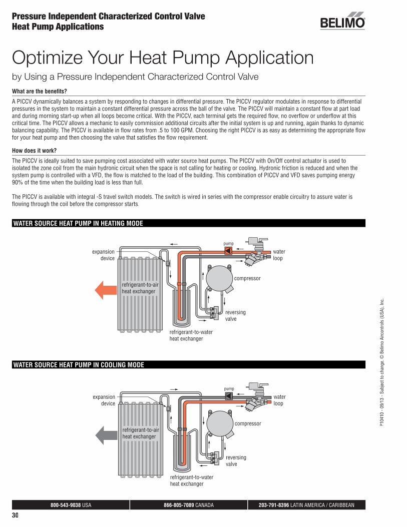
Pressure Independent Characterized Control ValveHeat Pump Applications
WATER SOURCE HEAT PUMP IN HEATING MODE
WATER SOURCE HEAT PUMP IN COOLING MODE
Optimize Your Heat Pump Applicationby Using a Pressure Independent Characterized Control ValveWhat are the benefi ts?
A PICCV dynamically balances a system by responding to changes in differential pressure. The PICCV regulator modulates in response to differential pressures in the system to maintain a constant differential pressure across the ball of the valve. The PICCV will maintain a constant fl ow at part load and during morning start-up when all loops become critical. With the PICCV, each terminal gets the required fl ow, no overfl ow or underfl ow at this critical time. The PICCV allows a mechanic to easily commission additional circuits after the initial system is up and running, again thanks to dynamic balancing capability. The PICCV is available in fl ow rates from .5 to 100 GPM. Choosing the right PICCV is as easy as determining the appropriate fl ow for your heat pump and then choosing the valve that satisfi es the fl ow requirement.
How does it work?
The PICCV is ideally suited to save pumping cost associated with water source heat pumps. The PICCV with On/Off control actuator is used to isolated the zone coil from the main hydronic circuit when the space is not calling for heating or cooling. Hydronic friction is reduced and when the system pump is controlled with a VFD, the fl ow is matched to the load of the building. This combination of PICCV and VFD saves pumping energy 90% of the time when the building load is less than full.
The PICCV is available with integral -S travel switch models. The switch is wired in series with the compressor enable circuitry to assure water is fl owing through the coil before the compressor starts.
800-543-9038 USA 866-805-7089 CANADA 203-791-8396 LATIN AMERICA / CARIBBEAN
33
P104
10 -
09/1
3 - S
ubje
ct to
cha
nge.
© B
elim
o Ai
rcon
trols
(USA
), In
c.
Instructions for FlowSetR™ Field Adjustment ofFlow and Valve Sizing and Selection
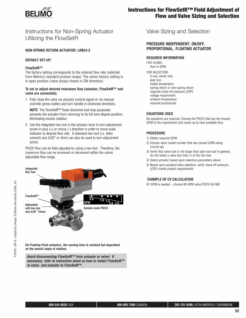
Instructions for Non-Spring ActuatorUtilizing the FlowSetR
NON-SPRING RETURN ACTUATOR: LRB24-3
DEFAULT SET-UP:
FlowSetR™The factory setting corresponds to the ordered flow rate (selected from Belimo’s standard product range). The valves factory setting is in open position (valve always closes in CW direction).
To set or adjust desired maximum flow (actuator, FlowSetR™ and valve are connected):
1. Fully close the valve via actuator control signal or via manualoverride (press button and turn handle in clockwise direction).
NOTE: The FlowSetR™ fixed clockwise end stop purposelyprevents the actuator from returning to its full zero-degree position,eliminating excess rotation.
2. Use the integrated hex tool in the actuator lever to turn adjustmentscrew in plus (+) or minus (-) direction in order to move scaleindicator to desired flow rate. A standard hex tool (i.e. Allenwrench) size 5/32” or 4mm can also be used to turn adjustmentscrew.
PICCV flow can be field adjusted by using a hex tool. Therefore, themaximum flow can be increased or decreased within the valvesadjustable flow range.
Adjustablewith hex tooolsize 5/32” [44mm]
Sample scale PICCV
FlowSetR™
IntegratedHex Tool
On Floating Point actuators, the running time is constant but dependent on the overall angle of rotation.
Avoid disconnecting FlowSetR™ from actuator or valve! If necessary, refer to instruction sheet on how to install FlowSetR™ to valve, and actuator to FlowSetR™.
Valve Sizing and Selection
PRESSURE INDEPENDENT, ON/OFF, PROPORTIONAL, FLOATING ACTUATOR
REQUIRED INFORMATIONFOR SIZING:
flow in GPM
FOR SELECTION:2-way valves onlypipe sizemedia temperaturespring return or non-spring returnrequired close-off pressure (COP)voltage requirementambient temperaturerequired accessories
EQUATIONS USEDNo equations are required. Choose the PICCV that has the closestGPM to the requirement and round up to next available flow.
PROCEDUREPROCEDURE1) Obtain required GPM2) Choose valve model number that has closest GPM rating
(round up) 3) Verify that valve size is not larger than pipe size and in general,
do not select a valve less than ½ of the line size4) Select actuator based upon selection parameters above5) Based upon actuator/valve selection, verify close-off pressure
(COP) meets project requirements
EXAMPLE OF CV CALCULATEXAMPLE OF CV CALCULATION87 GPM is needed – choose 90 GPM valve PICCV-50-090
800-543-9038 USA 866-805-7089 CANADA 203-791-8396 LATIN AMERICA / CARIBBEAN
34
P104
10 -
09/1
3 - S
ubje
ct to
cha
nge.
© B
elim
o Ai
rcon
trols
(USA
), In
c.
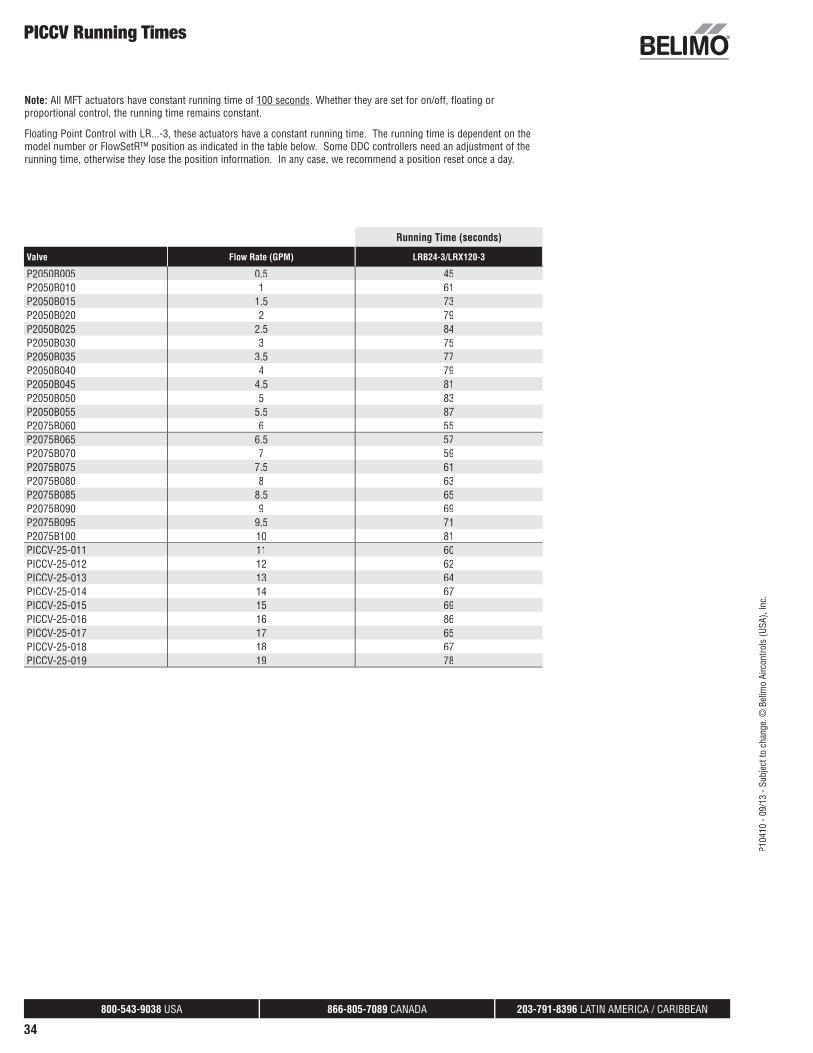
PICCV Running Times
Note: All MFT actuators have constant running time of 100 seconds. Whether they are set for on/off, floating or proportional control, the running time remains constant.
Floating Point Control with LR...-3, these actuators have a constant running time. The running time is dependent on the model number or FlowSetR™ position as indicated in the table below. Some DDC controllers need an adjustment of therunning time, otherwise they lose the position information. In any case, we recommend a position reset once a day.
Running Time (seconds)
Valve Flow Rate (GPM) LRB24-3/LRX120-3
P2050B005 0.5 45P2050B010 1 61P2050B015 1.5 73P2050B020 2 79P2050B025 2.5 84P2050B030 3 75P2050B035 3.5 77P2050B040 4 79P2050B045 4.5 81P2050B050 5 83P2050B055 5.5 87P2075B060 6 55P2075B065 6.5 57P2075B070 7 59P2075B075 7.5 61P2075B080 8 63P2075B085 8.5 65P2075B090 9 69P2075B095 9.5 71P2075B100 10 81PICCV-25-011 11 60PICCV-25-012 12 62PICCV-25-013 13 64PICCV-25-014 14 67PICCV-25-015 15 69PICCV-25-016 16 86PICCV-25-017 17 65PICCV-25-018 18 67PICCV-25-019 19 78
800-543-9038 USA 866-805-7089 CANADA 203-791-8396 LATIN AMERICA / CARIBBEAN
35
P104
10 -
09/1
3 - S
ubje
ct to
cha
nge.
© B
elim
o Ai
rcon
trols
(USA
), In
c.
Belimo PICCV Flow Verifi cation & Commissioning
FLOW
TYPICAL PARALLEL PIPING IN RELATION
TO THE INPUT AND OUTPUT
H/C–COIL
AIR VENT
PT PORT PT PORT
BELIMO PICCV (TYP.)
FLOW
SHUT–OFFVALVE
FLOW
DRAIN
PT PORT FLOW FLOWSTRAINER SHUT–OFFVALVE
UNION CONNECTION (TYP.)
(Optional)1
2 3a
Figure A
This document details the flow verification and commissioning procedures for PICCV (pressure independent characterized control valves). The flow verification techniques contained within thisdocument are optional and at the discretion of the MechanicalEngineer/Designer. These procedures are not mandatory to ensure proper operation of PICCV valves. Pressure independent control valvesare very different from pressure dependent control valves. Pressurevariations in the system will not affect flow through the valve. The ability to adjust and/or control the flow rate which passes through the PI valve is not possible through another mechanical device. Additionalmechanical devices should not be used. This makes the TAB/Commissioning process much different than with standard controlvalves. Pressure independent valves offer numerous maximum designflow values in each valve body size. It is important to note that most pressure independent valves will not travel a full 90 degrees of rotation when commanded to full design flow position. Design flow in a PICCVis adjusted through the maximum angle of ball travel. Therefore, if the valve’s maximum flow setting is not at the end of the range, the valvewill travel to a point less than 90 degrees. This is normal operation forpressure independent control valves.
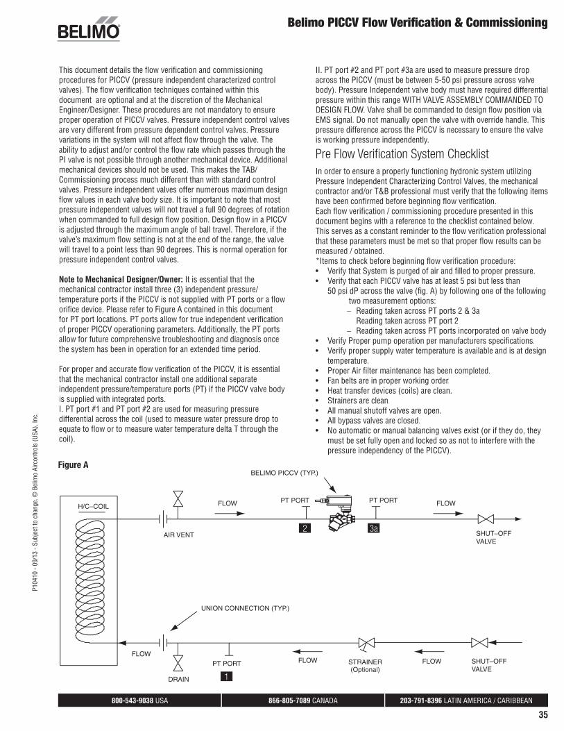
Note to Mechanical Designer/Owner: It is essential that themechanical contractor install three (3) independent pressure/temperature ports if the PICCV is not supplied with PT ports or a floworifice device. Please refer to Figure A contained in this documentfor PT port locations. PT ports allow for true independent verificationof proper PICCV operationing parameters. Additionally, the PT ports allow for future comprehensive troubleshooting and diagnosis once the system has been in operation for an extended time period.
For proper and accurate flow verification of the PICCV, it is essentialthat the mechanical contractor install one additional separateindependent pressure/temperature ports (PT) if the PICCV valve bodyis supplied with integrated ports.I. PT port #1 and PT port #2 are used for measuring pressuredifferential across the coil (used to measure water pressure drop toequate to flow or to measure water temperature delta T through thecoil).
II. PT port #2 and PT port #3a are used to measure pressure dropacross the PICCV (must be between 5-50 psi pressure across valvebody). Pressure Independent valve body must have required differentialpressure within this range WITH VALVE ASSEMBLY COMMANDED TODESIGN FLOW. Valve shall be commanded to design flow position via EMS signal. Do not manually open the valve with override handle. Thispressure difference across the PICCV is necessary to ensure the valveis working pressure independently.
Pre Flow Verifi cation System Checklist
In order to ensure a properly functioning hydronic system utilizingPressure Independent Characterizing Control Valves, the mechanicalcontractor and/or T&B professional must verify that the following itemshave been confirmed before beginning flow verification.Each flow verification / commissioning procedure presented in thisdocument begins with a reference to the checklist contained below.This serves as a constant reminder to the flow verification professionalthat these parameters must be met so that proper flow results can be measured / obtained.*Items to check before beginning flow verification procedure:• Verify that System is purged of air and filled to proper pressure.• Verify that each PICCV valve has at least 5 psi but less than
50 psi dP across the valve (fig. A) by following one of the followingtwo measurement options:− Reading taken across PT ports 2 & 3a− Reading taken across PT port 2− Reading taken across PT ports incorporated on valve body
• Verify Proper pump operation per manufacturers specifications.• Verify proper supply water temperature is available and is at design
temperature.• Proper Air filter maintenance has been completed.• Fan belts are in proper working order.• Heat transfer devices (coils) are clean.• Strainers are clean.• All manual shutoff valves are open.• All bypass valves are closed.• No automatic or manual balancing valves exist (or if they do, they
must be set fully open and locked so as not to interfere with thepressure independency of the PICCV).
800-543-9038 USA 866-805-7089 CANADA 203-791-8396 LATIN AMERICA / CARIBBEAN
36
P104
10 -
09/1
3 - S
ubje
ct to
cha
nge.
© B
elim
o Ai
rcon
trols
(USA
), In
c.
Belimo PICCV Flow Verifi cation & Commissioning
Below are the accepted procedures for verifying/commissioning pressure independent control valves.
Procedure #1 (System Verifi cation) – Total System
Flow Method
Verification for PICCV Cooling Valves/Heating Valves1. Verify that System is in proper working order. *See Items to check
before beginning flow verification procedure contained at thebeginning of this document.
2. Command open all PICCVs in a given system via the buildingautomation system if the total connected load matches the pumpcapacity and system diversity = 100%. Systems with less than100% diversity need to have a % of valves closed to match pumpcapacity.
3. Ensure that pumps are commanded to 100% speed (or VFD controlloop has high enough dP setpoint to satisfy connected load).
4. Verify total system flow is at system design flow rate via accuratemethod:
Calibrated Circuit Setter on main lines OrificeVenturiUltrasonic Flowmeter
5. Decrease the pump speed (or decrease dP setpoint if under control)until a measureable flow decrease occurs.
6. Increase pump speed (or increase dP setpoint if under control)slowly until design flow is reestablished. Make note of this finalmeasured dP. This will be the correct system dP operating setpoint.
NOTE: If total flow does not match design flow then troubleshooting must be done to determine cause. This may involve verifying flows at the terminal level.
Procedure #2 (Terminal Level Verifi cation) –
Air DeltaT Method
Verification for PICCV Cooling Valves/Heating Valves1. Verify that System is in proper working order. *See Items to check
before beginning flow verification procedure contained at thebeginning of this document.
2. Ensure that water is at design temperature.3. Ensure that terminal airflow is at design airflow rate (cfm).4. Command open pressure independent characterized control valve to
maximum design flow position5. Reference approved engineering document containing design air
delta T for heating/cooling coil associated with correspondingpressure independent characterized control valve.
6. Measure coil inlet air temperature and coil discharge airtemperature.
7. Difference between coil inlet air reading and coil discharge airreading should equal or exceed design air delta T.
Procedure #3 (Terminal Level Verifi cation) – Water
DeltaT Method
Verification for PICCV Cooling Valves/Heating Valves1. Verify that System is in proper working order. *See Items to check
before beginning flow verification procedure contained at thebeginning of this document.
2. Ensure that water is at design temperature.3. Ensure that terminal airflow is at design flow rate (cfm).4. Command open pressure independent characterized control valve to
maximum design flow position.
5. Reference approved engineering document containing design waterdeltaT for heating/cooling coil associated with correspondingpressure independent characterized control valve.
6. Measure water temperature differential of coil by using PT ports#1 and #2 as referenced in Figure A. PICCV models with factoryprovided PT ports measure the water temperature differential ofthe coil.
7. Measured temperature differential should be equal to designed watertemperature differential.
Procedure #4 (Terminal Level Verifi cation) –
Coil dP (DeltaP) Method
Verification for PICCV Cooling Valves and PICCV Heating Valves1. Verify that System is in proper working order. *See Items to check
before beginning flow verification procedure contained at thebeginning of this document.
2. Command open pressure independent characterized control valve tomaximum design flow position.
3. Reference approved engineering document containing design coilwater pressure drop (usually expressed in ft. of H2O) fordesign flow. This value will be for the heating/cooling coil associatedwith corresponding pressure independent characterized controlvalve.
4. Measure coil dP by using PT ports #1 & #2 as referenced in Fig. A.Adjust the angle of the actuator so the differential pressre across theorifice matches the flow required on the table located on page 3.
5. Formula to calculate flow is:
Actual GPM = √(Measured Coil dP/Design Coil dP) x Design GPMNote: Coil dP and Design dP expressed in feet of H2O.
Procedure #5 (Terminal Level Verifi cation) –
Coil Flow for PICCV-F Models with Factory Provided
Flow Orifi ce
1. Verify that System is in proper working order. *See Items to checkbefore beginning flow verification procedure contained at thebeginning of this document.
2. Command open pressure independent characterized control valve tomaximum design flow position.
3. Connect differential pressure gauge to the flow orifice device’s highand low pressure PT ports. Reference the gauge reading in the fieldto the provided published chart to determine the flow rate.
4. All PICCV assemblies with flow orifice are motorized withproportional control LRB24-SA or floating point control KRB24-3actuators. They are shipped from the Belimo factory with default flowsetting equal to the maximum Gallons Per Minute (GPM) rating ofthe valve body. When the coil design GPM is less than the PICCVfactory default, the user must manually set the actuator travel limitto match the flow rate of the coil. The travel limit of the LRB24-SAis set with a simple electronic push button and the KRB24-3 is setmechanically with a fine tooth gear travel limit mechanism. The new“field set” PICCV maximum flow rate is validated with the flow orificemethodology.
800-543-9038 USA 866-805-7089 CANADA 203-791-8396 LATIN AMERICA / CARIBBEAN
37
P104
10 -
09/1
3 - S
ubje
ct to
cha
nge.
© B
elim
o Ai
rcon
trols
(USA
), In
c.
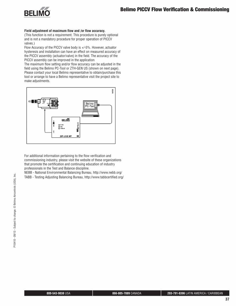
For additional information pertaining to the flow verification andcommissioning industry, please visit the website of these organizationsthat promote the certification and continuing education of industry professionals in the Test and Balance discipline.NEBB - National Environmental Balancing Bureau, http://www.nebb.org/TABB - Testing Adjusting Balancing Bureau, http://www.tabbcertified.org/
Field adjustment of maximum flow and /or flow accuracy. (This function is not a requirement. This procedure is purely optionaland is not a mandatory procedure for proper operation of PICCVvalves.)Flow Accuracy of the PICCV valve body is +/-5%. However, actuatorhysteresis and installation can have an effect on measured accuracy ofthe PICCV assembly (actuator/valve) in the field. The accuracy of the PICCV assembly can be improved in the application.The maximum flow setting and/or flow accuracy can be adjusted in thefield using the Belimo PC-Tool or ZTH-GEN US (shown on next page).Please contact your local Belimo representative to obtain/purchase thistool or arrange to have a Belimo representative visit the project site to make adjustments.
Belimo PICCV Flow Verifi cation & Commissioning

800-543-9038 USA 866-805-7089 CANADA 203-791-8396 LATIN AMERICA / CARIBBEAN
38
P104
10 -
09/1
3 - S
ubje
ct to
cha
nge.
© B
elim
o Ai
rcon
trols
(USA
), In
c.
Flow Setting and Verifi cation for Field Set ActuatorsKRB24-3, LRB24-SA
KRB24-3 Field Setting Coil Maximum Flow ProcedureThe KRB24-3 actuator factory defaults flow setting is equal to the maximum GPM of the valve body it motorizes. If coil design maximum flow is less than the factory default, follow “field set” procedures below.
To field set or adjust the desired maximum flow:
Step 1: With Actuator powered by 24VAC place factory provided magnet on actuator magnetic gear release area to release internal lockmechanism, allowing the indicator wheel to rotate freely. A click will beheard when it is released.
Step 2: Access the locking tab by rotating the actuator and associatedflow indicator away from the locking tab.
Step 3: Using a small flat head screwdriver remove the locking tabby prying out from the bottom. Replace after new position is set according to step 4.
Step 4a: Select the valve body and desired flow on the flow table attached to the power cable of the actuator; rotate the flow indicator on the top of the actuator to the desired position on the equal percentage scale. Manually position the actuator travel limit (right side edge withscale facing your view) to equal coil maximum flow.
Step 4b: For –F models with flow orifice manually rotate the actuator until the measured flow matches the coil differential pressure gauge reading (inches w.c.) and flow reference from provided chart below.Manually position the actuators locking tab to make contact with theright side of the travel limit.
Step 5: Reattach the locking tab to the actuator by first engaging at the top with a slight approach angle, and then push down to engage thebottom. A click will be heard when the locking tab is fully seated.
Step 6: Remove the magnet from the actuator and retain for future use. Replacement magnets are available with part number 10861-0001.
LRB24-SA Field Setting Coil Maximum Flow ProcedureThe LRB24-SA actuator factory defaults flow setting is equal to the maximum GPM of the valve body it motorizes. If coil design maximum flow is less than the factory default, follow “field set” procedures below.
To set or adjust the desired maximum flow:
Step 1: With the actuator powered by 24VAC depress the black gearrelease mechanism on the actuator and press down until the lockingtab engages to the side of the actuator. If done correctly a click will be heard and gear release will stay depressed.
800-543-9038 USA 866-805-7089 CANADA 203-791-8396 LATIN AMERICA / CARIBBEAN
39
P104
10 -
09/1
3 - S
ubje
ct to
cha
nge.
© B
elim
o Ai
rcon
trols
(USA
), In
c.Flow Setting and Verifi cation for Field Set Actuators
KRB24-3, LRB24-SA
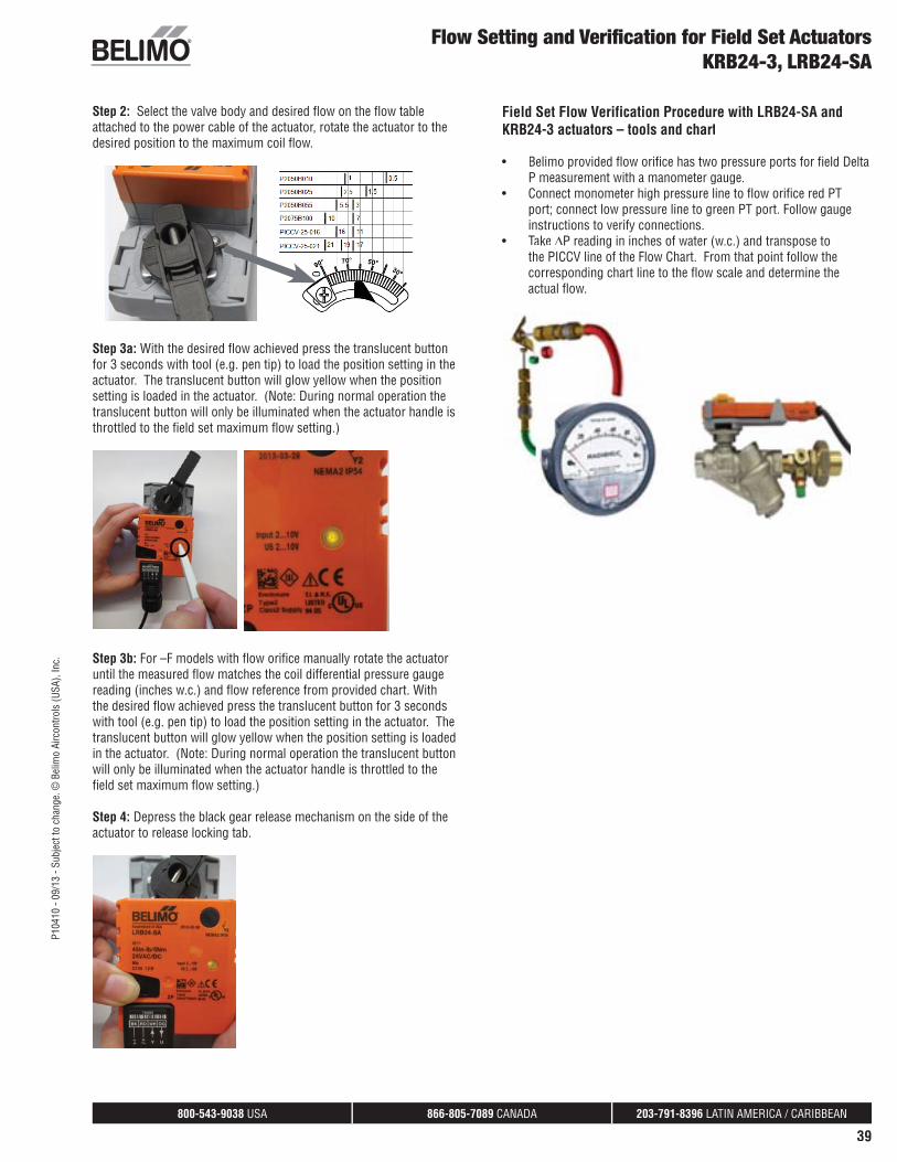
Step 2: Select the valve body and desired flow on the flow table attached to the power cable of the actuator, rotate the actuator to the desired position to the maximum coil flow.
Step 3a: With the desired flow achieved press the translucent button for 3 seconds with tool (e.g. pen tip) to load the position setting in theactuator. The translucent button will glow yellow when the position setting is loaded in the actuator. (Note: During normal operation the translucent button will only be illuminated when the actuator handle isthrottled to the field set maximum flow setting.)
Step 3b: For –F models with flow orifice manually rotate the actuator until the measured flow matches the coil differential pressure gauge reading (inches w.c.) and flow reference from provided chart. With the desired flow achieved press the translucent button for 3 secondswith tool (e.g. pen tip) to load the position setting in the actuator. Thetranslucent button will glow yellow when the position setting is loadedin the actuator. (Note: During normal operation the translucent buttonwill only be illuminated when the actuator handle is throttled to thefield set maximum flow setting.)
Step 4: Depress the black gear release mechanism on the side of theactuator to release locking tab.
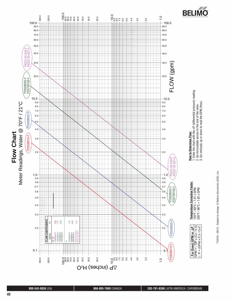
Field Set Flow Verification Procedure with LRB24-SA andKRB24-3 actuators – tools and chart
• Belimo provided flow orifice has two pressure ports for field DeltaP measurement with a manometer gauge.
• Connect monometer high pressure line to flow orifice red PTport; connect low pressure line to green PT port. Follow gaugeinstructions to verify connections.
• Take ΔP reading in inches of water (w.c.) and transpose tothe PICCV line of the Flow Chart. From that point follow thecorresponding chart line to the flow scale and determine theactual flow.
800-543-9038 USA 866-805-7089 CANADA 203-791-8396 LATIN AMERICA / CARIBBEAN
40
P104
10 -
09/1
3 - S
ubje
ct to
cha
nge.
© B
elim
o Ai
rcon
trols
(USA
), In
c.
2
1 2
P2
050B
055-
F
Flow
Cha
rtM
eter
Rea
ding
s, W
ater
@ 7
0°F
/ 21°
CP2
050B
010-
F
P205
0B01
0-F
P205
0B02
5-F
P205
0B02
5-F
P205
0B01
0-F
P205
0B02
5-F
P205
0B02
5-F
P207
5B10
0-F
P205
0B05
5-F
P207
5B10
0-F
PICC
V-25
-016
-FPI
CCV-
25-0
21-F
P205
0B05
5-F
P207
5B10
0-F
P205
0B05
5-F
P207
5B10
0-F
PICC
V-25
-016
-FPI
CCV-
25-0
21-F
PICC
V-25
-016
-FPI
CCV-
25-0
21-F
Tem
pera
ture
Cor
rect
ion
Fact
or:
155°
F / 6
8°C
= 1.
01 x
GPM
205°
F / 9
6°C
= 1.
02 x
GPM
How
to D
eter
min
e Fl
ow:
1. E
nter
the
char
t with
the
P (d
iffer
entia
l pre
ssur
e) re
adin
g.2.
Go
horiz
onta
lly a
cros
s to
the
size
of t
he v
alve
.3.
Go
verti
cally
up
or d
own
to re
ad th
e GP
M (f
low
).
800-543-9038 USA 866-805-7089 CANADA 203-791-8396 LATIN AMERICA / CARIBBEAN
41
P104
10 -
09/1
3 - S
ubje
ct to
cha
nge.
© B
elim
o Ai
rcon
trols
(USA
), In
c.Operating Instructions
ZTH-GEN US
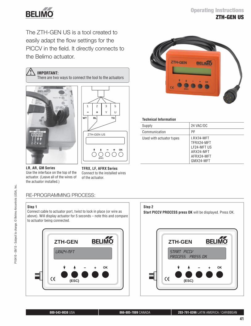
The ZTH-GEN US is a tool created toeasily adapt the fl ow settings for thePICCV in the fi eld. It directly connects tothe Belimo actuator.
ZTH-GEN
(ESC)
ZTH-GEN
(ESC)
Technical Information
Supply 24 VAC/DC
Communication PP
Used with actuator types LRX24-MFTTFRX24-MFT LF24-MFT USARX24-MFTAFRX24-MFTGMX24-MFT
ZTH-GEN US
1 2 3
Y U
5
(ESC)
IMPORTANT:There are two ways to connect the tool to the actuators
LR, AR, GM SeriesUse the interface on the top of theactuator. (Leave all of the wires of the actuator installed.)
TFRX, LF, AFRX SeriesConnect to the installed wiresof the actuator.
RE-PROGRAMMING PROCESS:
Step 1Connect cable to actuator port, twist to lock in place (or wire as above). Will display actuator for 5 seconds – note this and compare to actuator being connected.
Step 2Start PICCV PROCESS press OK will be displayed. Press OK.
LRX24-MFT START PICCVPROCESS press ok
WT BL TQ
800-543-9038 USA 866-805-7089 CANADA 203-791-8396 LATIN AMERICA / CARIBBEAN
42
P104
10 -
09/1
3 - S
ubje
ct to
cha
nge.
© B
elim
o Ai
rcon
trols
(USA
), In
c.
Operating InstructionsZTH-GEN US
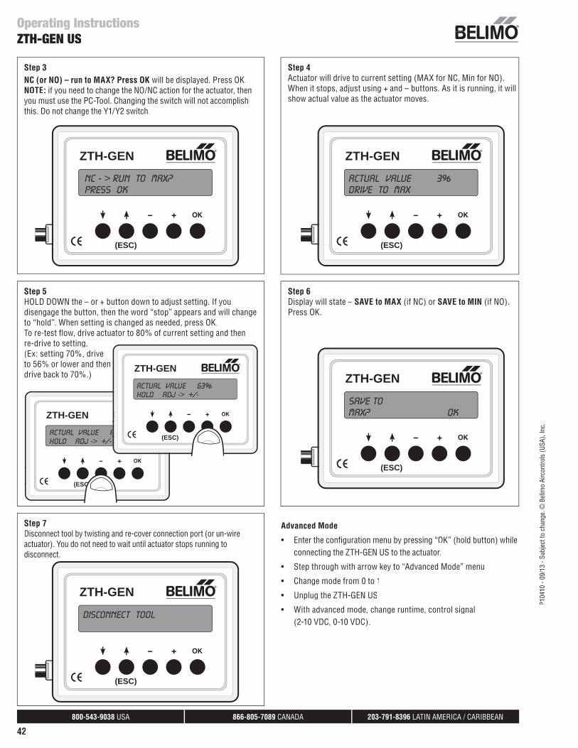
Step 3NC (or NO) – run to MAX? Press OK will be displayed. Press OK.NOTE: if you need to change the NO/NC action for the actuator, then you must use the PC-Tool. Changing the switch will not accomplish this. Do not change the Y1/Y2 switch.
Step 5HOLD DOWN the – or + button down to adjust setting. If you disengage the button, then the word “stop” appears and will change to “hold”. When setting is changed as needed, press OK.To re-test flow, drive actuator to 80% of current setting and thenre-drive to setting.(Ex: setting 70%, drive to 56% or lower and thendrive back to 70%.)
Step 7Disconnect tool by twisting and re-cover connection port (or un-wireactuator). You do not need to wait until actuator stops running to disconnect.
Step 4Actuator will drive to current setting (MAX for NC, Min for NO). When it stops, adjust using + and – buttons. As it is running, it willshow actual value as the actuator moves.
Step 6Display will state – SAVE to MAX (if NC) or SAVE to MIN (if NO). Press OK.
Advanced Mode
• Enter the configuration menu by pressing “OK” (hold button) whileconnecting the ZTH-GEN US to the actuator.
• Step through with arrow key to “Advanced Mode” menu
• Change mode from 0 to 1
• Unplug the ZTH-GEN US
• With advanced mode, change runtime, control signal(2-10 VDC, 0-10 VDC).
ZTH-GEN
(ESC)
ZTH-GEN
(ESC)
ZTH-GEN
(ESC)
ZTH-GEN
(ESC)
NC - > run to MAX?press ok
actual value 3%drive to MAX
Save toMAX? ok
disconnect tool
ZTH-GEN
(ESC)
actual value 6hold adj -> +/-
ZTH-GEN
(ESC)
actual value 63%hold adj -> +/-
Recommended


![PICCV NG databook EN (F) - Belimo05.08.2009UPDATE].pdf · Energy savings with maximum convenience and low installation cost ... thenecessarydelivery height p ofthemainpump depends](https://img.pdfslide.net/doc/110x75/5b900eb409d3f20e308d5c54/piccv-ng-databook-en-f-05082009updatepdf-energy-savings-with-maximum.jpg)