Presto XL Seriesand
ECOA HLT SeriesScissor Lifts
Installation, Operationand Service Manual
Model Number ___________________
Serial # _________________________
Date placed in service _____________
IMPORTANT: READ CAREFULLYBEFORE INSTALLING OR OPERATING LIFT
Part orders are subject to a $50 minimum charge.
January 2017

Page 2 Presto/ECOA Lifts owner's manual: XL Series and HLT Series
This manual was current at the time of printing. To obtain the latest, most updated version, please contact Presto ECOA Customer Service Department or go to our website: www.PrestoLifts.com where you will find a complete list of current owner’s manuals to print.
Presto/ECOA Lifts owner's manual: XL Series and HLT Series Page 3
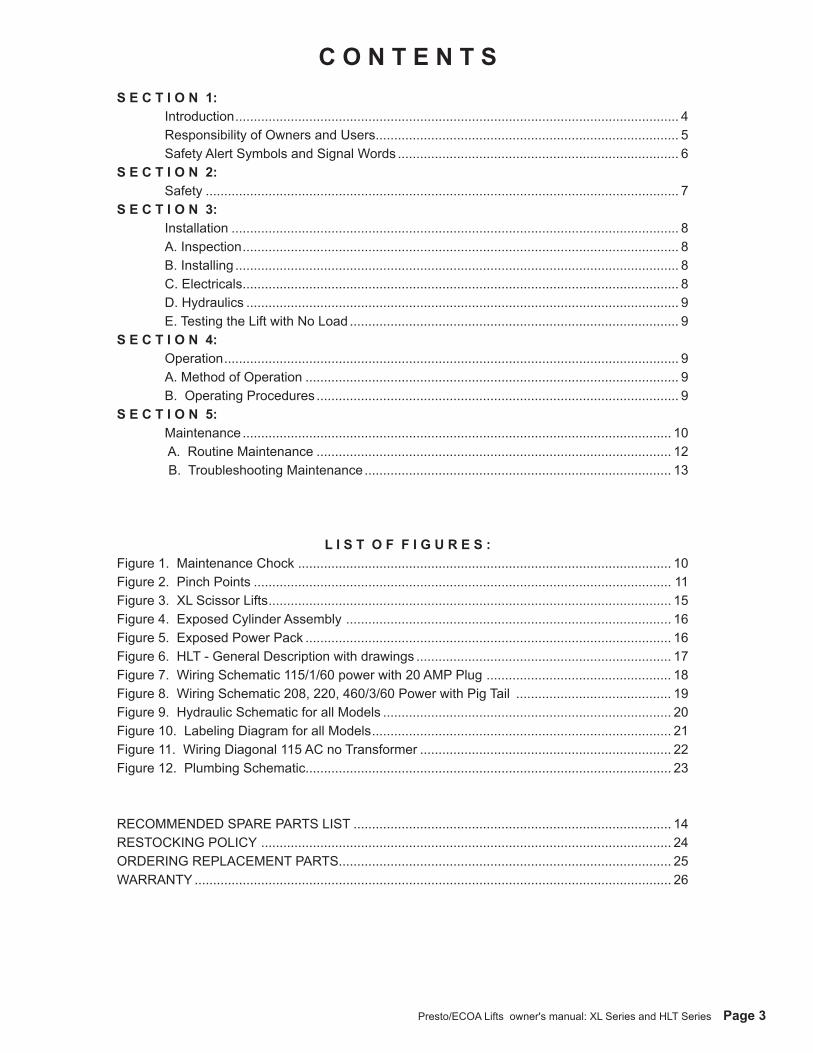
C O N T E N T SS E C T I O N 1: Introduction ........................................................................................................................ 4 Responsibility of Owners and Users .................................................................................. 5 Safety Alert Symbols and Signal Words ............................................................................ 6S E C T I O N 2: Safety ................................................................................................................................ 7S E C T I O N 3: Installation ......................................................................................................................... 8 A. Inspection ...................................................................................................................... 8 B. Installing ........................................................................................................................ 8 C. Electricals ...................................................................................................................... 8 D. Hydraulics ..................................................................................................................... 9 E. Testing the Lift with No Load ......................................................................................... 9S E C T I O N 4: Operation ........................................................................................................................... 9 A. Method of Operation ..................................................................................................... 9 B. Operating Procedures .................................................................................................. 9S E C T I O N 5: Maintenance .................................................................................................................... 10 A. Routine Maintenance ................................................................................................ 12 B. Troubleshooting Maintenance ................................................................................... 13
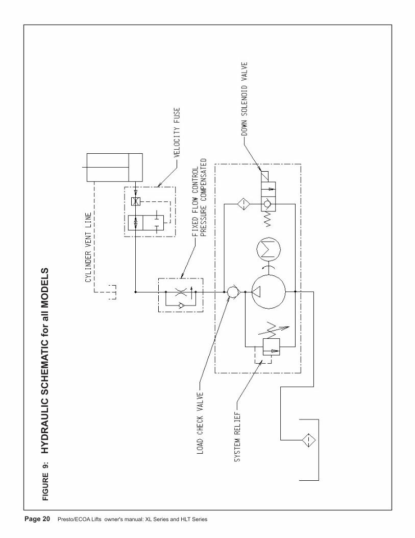
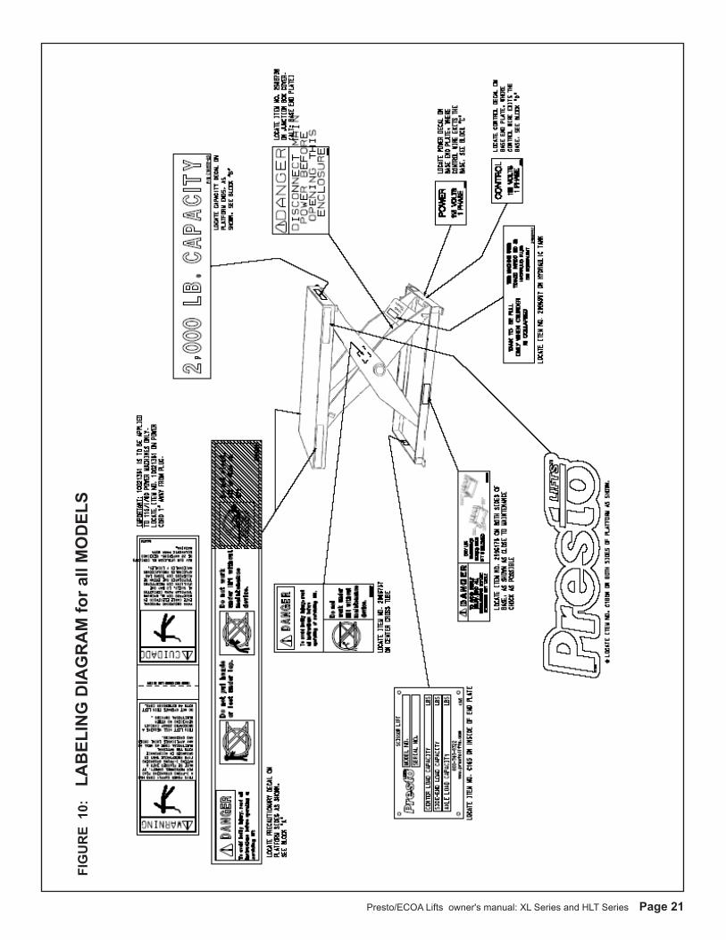
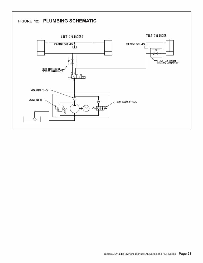
L I S T O F F I G U R E S :Figure 1. Maintenance Chock ..................................................................................................... 10Figure 2. Pinch Points ................................................................................................................. 11Figure 3. XL Scissor Lifts ............................................................................................................. 15Figure 4. Exposed Cylinder Assembly ........................................................................................ 16Figure 5. Exposed Power Pack ................................................................................................... 16Figure 6. HLT - General Description with drawings ..................................................................... 17Figure 7. Wiring Schematic 115/1/60 power with 20 AMP Plug .................................................. 18Figure 8. Wiring Schematic 208, 220, 460/3/60 Power with Pig Tail .......................................... 19Figure 9. Hydraulic Schematic for all Models .............................................................................. 20Figure 10. Labeling Diagram for all Models ................................................................................. 21Figure 11. Wiring Diagonal 115 AC no Transformer .................................................................... 22Figure 12. Plumbing Schematic................................................................................................... 23
RECOMMENDED SPARE PARTS LIST ...................................................................................... 14RESTOCKING POLICY ............................................................................................................... 24ORDERING REPLACEMENT PARTS.......................................................................................... 25WARRANTY ................................................................................................................................. 26
Page 4 Presto/ECOA Lifts owner's manual: XL Series and HLT Series
S E C T I O N 1
INTRODUCTIONThis manual attempts to provide all of the information necessary for the safe and proper in-stallation, operation and maintenance of XL and HLT Series Scissor Lifts. It is important that all personnel involved with the installation, maintenance or operation of the scissor lift read this manual.
Where unique situations arise, that are not covered in this manual, call Presto/ECOA Lifts for further instructions. Additional manuals are available upon request or on our web site at www.prestolifts.com.
The scissor lift has a nameplate that provides the load capacity ratings, serial number and model identifications. Please refer to these numbers when ordering parts or requesting further information.
The XL and HLT Series Lifts are designed for lifting, lowering and positioning a variety of loads. WHERE UNIQUE SITUATIONS ARISE, THAT ARE NOT COVERED IN THIS MANUAL, CALL PRESTO LIFTS FOR FURTHER INSTRUCTIONS.
The XL and HLT Series are designed for inplant/nonhazardous location use only. These units are not for personnel lifting.
Presto/ECOA Lifts owner's manual: XL Series and HLT Series Page 5
Responsibility of Owners and Users
Inspection and MaintenanceThe device shall be inspected and maintained in proper working order in accordance with Presto/ECOA Lifts owner’s manual.
Removal from ServiceAny device not in safe operating condition such as, but not limited to, excessive leakage, missing rollers, pins, or fasteners, any bent or cracked structural members, cut or frayed electric, hydraulic, or pneumatic lines, damaged or malfunctioning controls or safety devices, etc. shall be removed from service until it is repaired to the original manufacturer’s standards.
RepairsAll repairs shall be made by qualified personnel in conformance with Presto/ECOA Lifts' instructions.
OperatorsOnly trained personnel and authorized personnel shall be permitted to operate these lifts.
Before OperationBefore using the device, the operator shall have:• Read and/or had explained, and understood, the manufacturer’s operating instructions and
safety rules.• Inspected the device for proper operation and condition. Any suspect item shall be carefully
examined and a determination made by a qualified person as to whether it constitutes a hazard. All items not in conformance with Presto/ECOA Lifts’ specification shall be corrected before further use of these lifts.
During OperationThe device shall only be used in accordance with this owner’s manual.• Do not overload.• Ensure that all safety devices are operational and in place.
Modifications or AlterationsModifications or alterations to any Presto industrial positioning equipment shall be made only with written permission from Presto/ECOA Lifts.
Page 6 Presto/ECOA Lifts owner's manual: XL Series and HLT Series
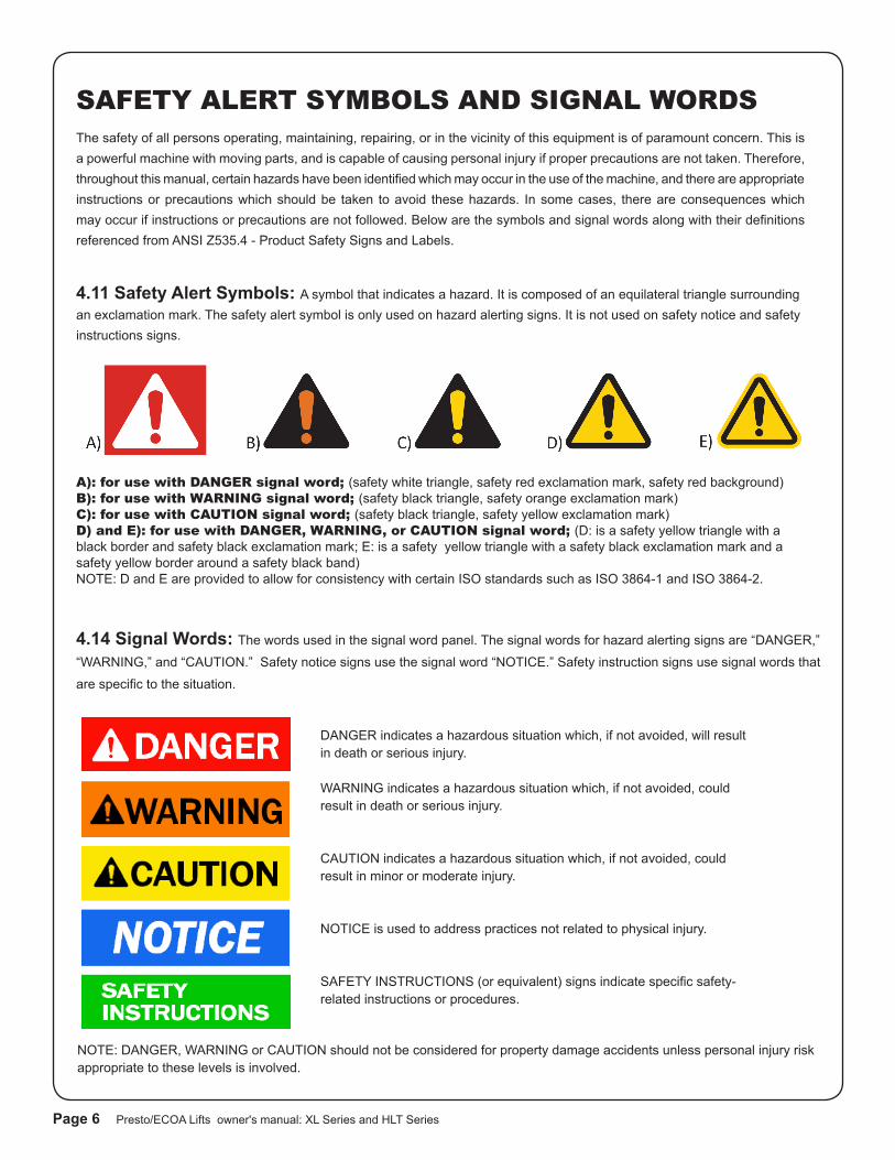
SAFETY ALERT SYMBOLS AND SIGNAL WORDSThe safety of all persons operating, maintaining, repairing, or in the vicinity of this equipment is of paramount concern. This is a powerful machine with moving parts, and is capable of causing personal injury if proper precautions are not taken. Therefore, throughout this manual, certain hazards have been identified which may occur in the use of the machine, and there are appropriate instructions or precautions which should be taken to avoid these hazards. In some cases, there are consequences which may occur if instructions or precautions are not followed. Below are the symbols and signal words along with their definitions referenced from ANSI Z535.4 - Product Safety Signs and Labels.
4.11 Safety Alert Symbols: A symbol that indicates a hazard. It is composed of an equilateral triangle surrounding an exclamation mark. The safety alert symbol is only used on hazard alerting signs. It is not used on safety notice and safety instructions signs.
4.14 Signal Words: The words used in the signal word panel. The signal words for hazard alerting signs are “DANGER,”
“WARNING,” and “CAUTION.” Safety notice signs use the signal word “NOTICE.” Safety instruction signs use signal words that
are specific to the situation.
DANGER indicates a hazardous situation which, if not avoided, will result in death or serious injury.
WARNING indicates a hazardous situation which, if not avoided, could result in death or serious injury.
CAUTION indicates a hazardous situation which, if not avoided, could result in minor or moderate injury.
NOTICE is used to address practices not related to physical injury.
SAFETY INSTRUCTIONS (or equivalent) signs indicate specific safety-related instructions or procedures.
NOTE: DANGER, WARNING or CAUTION should not be considered for property damage accidents unless personal injury risk appropriate to these levels is involved.
A): for use with DANGER signal word; (safety white triangle, safety red exclamation mark, safety red background)B): for use with WARNING signal word; (safety black triangle, safety orange exclamation mark)C): for use with CAUTION signal word; (safety black triangle, safety yellow exclamation mark)D) and E): for use with DANGER, WARNING, or CAUTION signal word; (D: is a safety yellow triangle with a black border and safety black exclamation mark; E: is a safety yellow triangle with a safety black exclamation mark and a safety yellow border around a safety black band)NOTE: D and E are provided to allow for consistency with certain ISO standards such as ISO 3864-1 and ISO 3864-2.
Presto/ECOA Lifts owner's manual: XL Series and HLT Series Page 7
S E C T I O N 2
SAFETYThe safety of all persons installing, using, servicing, or working near the unit is of paramount concern to Presto/ECOA Lifts. The lift is a powerful machine with moving parts, and is capable of causing personal injury if proper precautions are not taken. Therefore, throughout this manual, Presto/ECOA Lifts have identified certain hazards, which may occur in the use of the unit, and provided appropriate instructions or precautions that should be taken to avoid these hazards. In some cases, Presto/ECOA Lifts has also pointed out the consequences that may occur if Presto/ECOA Lifts instructions or precautions are not followed. Presto/ECOA Lifts use the following nationally recognized system for identifying the severity of the hazards associated with its products:
DANGER – Immediate hazard that will result in severe personal injury or death.
WARNING – Hazard or unsafe practice, that could result in severe personal injury or death.
CAUTION – Hazard or unsafe practice, that could result in minor personal injury or property damage.
In the interest of safety, please read the entire manual carefully. You must understand the material in this manual before you install, use, or service the unit. If you have any question about any of the instructions in this manual, please contact Presto/ECOA Lifts at 1-800-343-9322.
Page 8 Presto/ECOA Lifts owner's manual: XL Series and HLT Series
S E C T I O N 3
INSTALLATIONA. INSPECTION:
Upon receipt of the XL or HLT Series Scissor Lift, inspect the equipment completely to determine if there is any ship-ping damage, and that the lift is complete. Presto tests and inspects every piece of equipment prior to shipment. If damage is apparent, a freight claim must be filed with the freight company. Do Not use the lift if there appears to be any damage. With the lift in a collapsed position, check the following:
rCheck for signs of damage especially to the electrical and hydraulic components.
rCheck all connections for tightness. Is there hydraulic fluid visible?
rCheck base frame for flatness.
rInspect for any bent or damaged metal parts.
B: INSTALLING
Before starting, be sure that the electrical system is wired and is in full compliance with local electrical codes and ordi-nances. Read all of the instructions prior to starting the lift.
Floor Installationa) Make sure that the floor in the installation area is level, stable and free from dirt and surface defects.
b) Place lift in exact operating position.
CAUTION!When moving the lift, do not ever attempt to pick it up by the platform. The lift should be picked up by the base frame only. The use of a strap sling is suggested. If the lift has optional lifting eyebolts, attach a chain spreader and raise the lift from a center position. Be sure the eyebolts are secured in place with locking nuts prior to lifting.
c) Make sure that the complete base of the lift is in contact with the floor. In order to provide complete contact with the floor, the base may be shimmed or grouted.
CAUTION!Do not spot shim. The complete base must be in con-tact with the floor or shims.
d) If the lift is provided with anchor holes or brackets, be sure the lift has been placed in the exact operating position before spotting or drilling holes for anchor bolts. Bolt the lift securely before using it.
e) For lifts with remote power units, locate and bolt the power unit in place, so as to provide easy access. Do not obstruct the operator's work area. Make hydraulic connections ac-cording to the information contained in Section 3D.f) Electrical connections must be made according to the electrical schematics and information contained in Section 3C and in compliance to local codes and ordinances.
Pit Mounted Installationa) Build pit to standard pit dimension as outlined in your pit plan - if supplied, paying careful attention to raceway, sump, clearance and height requirements.
b) The remaining steps are the same as required for floor installation. See Section 3B (1b to 1f).
WARNING!Do not install lifts in pits unless they haveapproved bevel edge top or electro-mechanical toe guards.
CAUTION!Lifts with toeguard and oversized platformsmust be secured with at least 4 anchor boltswith a minimum of 2000-lb pullout strength for each bolt.
C. ELECTRICALS
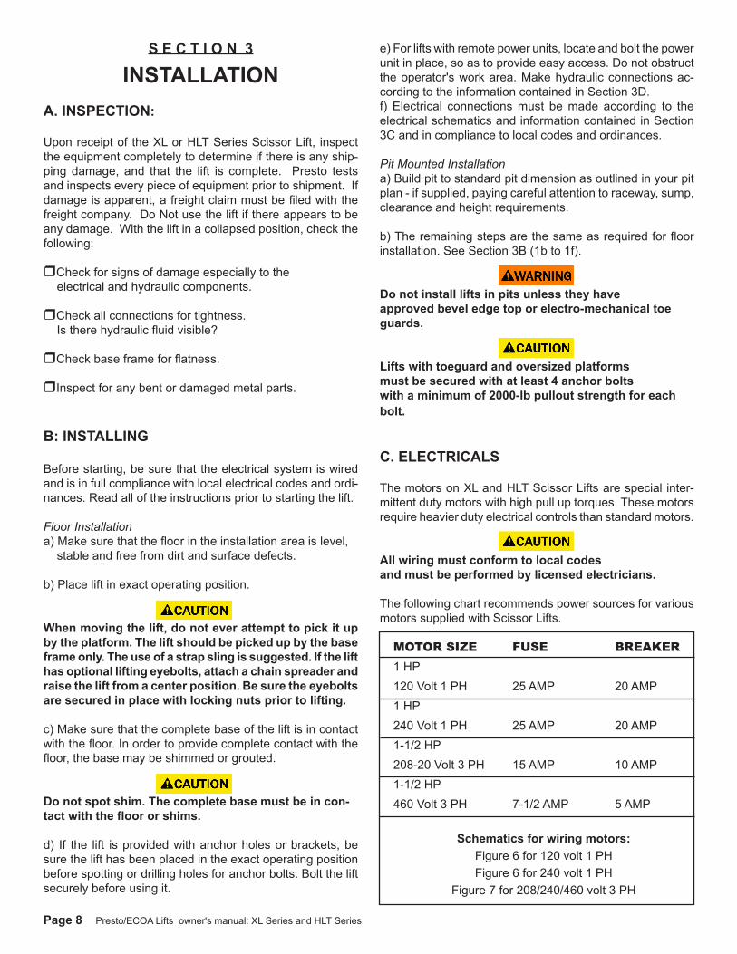
The motors on XL and HLT Scissor Lifts are special inter-mittent duty motors with high pull up torques. These motors require heavier duty electrical controls than standard motors.
CAUTION!All wiring must conform to local codesand must be performed by licensed electricians.
The following chart recommends power sources for various motors supplied with Scissor Lifts.
MOTOR SIZE FUSE BREAKER1 HP120 Volt 1 PH 25 AMP 20 AMP1 HP240 Volt 1 PH 25 AMP 20 AMP1-1/2 HP208-20 Volt 3 PH 15 AMP 10 AMP1-1/2 HP460 Volt 3 PH 7-1/2 AMP 5 AMP
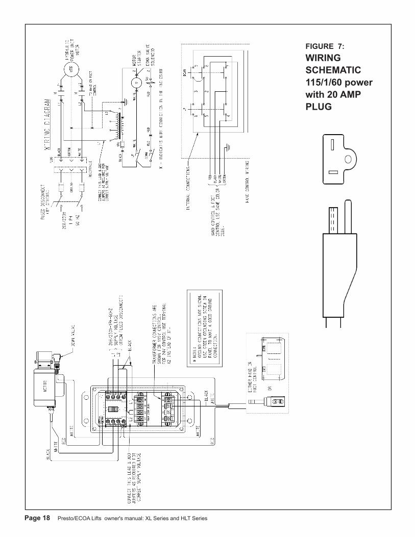
Schematics for wiring motors:Figure 6 for 120 volt 1 PHFigure 6 for 240 volt 1 PH
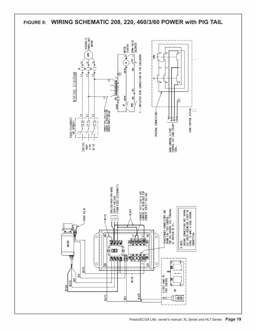
Figure 7 for 208/240/460 volt 3 PH
Presto/ECOA Lifts owner's manual: XL Series and HLT Series Page 9
S E C T I O N 4
OPERATION
A. METHOD OF OPERATION
All Presto Scissor Lifts are provided with a special relief valve and are factory preset for the maximum safe capacity of the lift. Activating and holding the up switch will energize the motor. The motor is attached to a positive displacement pump, that draws hydraulic fluid from the reservoir and transfers it under pressure to the cylinder. This forces the piston forward and the scissor legs to separate and raise the platform, releasing the up button will stop the lift. A check valve between the pump and piston holds the table in posi-tion. Depressing and holding the down switch will energize a solenoid, that allows the oil from the cylinder to return to the reservoir through a preset flow control. This allows the lift to lower smoothly and at a controlled speed.
B. OPERATING INSTRUCTIONS
In order to operate the lift follow these operating procedures.
Read and understand all the instructions before operating. If the lift has modifications or accessories, read and understand their functions.
1). Load the lift correctly.a). Do not load the lift while it is running.b). Do not exceed the maximum rated load (note that
load capacity is reduced due to side or end loading.)c). Place load in the center of table.d). If the load is unstable or may become unstable, fasten
it into position.
2). Operate the lift.a). To raise the lift, press and hold the up button.b). To lower the lift, press and hold the down
button.c). Release the button to stop the lift.
3). Wait until the lift has come to a complete stop before unloading the lift.
4). Stand clear of lift when operating it in order to avoid injury.
WARNING!a). Do not stand, sit or climb onto the lift.b). Do not load or unload a moving lift.c). If the lift fails to move or exhibits strange movements or sound, stop immediately. Do not operate the lift until it has been checked and repaired.d). Obey all warning labels.
D. HYDRAULICS
1. Use hydraulic oil only for the lift. The lift has been supplied with Conoco Super Hydraulic 32.2. Before using the lift, check the hydraulic oil level and add oil if necessary. Check fittings for tightness. .3. External power pack units also require that the hydraulic lines be blown out with clean air. Then attach to hydraulic fittings per hydraulic schematic. Figure 8.
CAUTION!XL and HLT Series Scissor Lifts are designed for normal factory environments. Where below freezing conditions may exist, special fluid must be used. Contact Presto for further information when freezing conditions exist.
WARNING!Do not use automotive hydraulic, brake or trans-mission fluids. They will damage seals and pose a serious fire hazard.
E. TESTING THE LIFT WITH NO LOAD
1. Before testing the lift, clear the area of any loose material. Be sure the lift has no obstruction above it or on any side. Using the controls provided, briefly operate the lift (5-10 seconds). If the lift begins to rise with a humming sound and functions properly, continue to the full upright position.
CAUTION!If the lift does not rise immediately, or there is any op-erational problem, stop it immediately. Before continu-ing, check the rotation of the pump and motor and the voltage at motor terminals; again briefly operate the lift. If the lift does not move smoothly with a humming sound, stop and review the procedures in the section on troubleshooting (5B).
2. After raising the lift completely, lower the lift. It should move slowly and smoothly without a humming sound. If the lift operates properly, raise and lower the lift and stop at dif-ferent levels to get a good perspective on the lift's operations and movements.
WARNING!Do not tamper with or remove cover of the electrical junction box. Only authorized, qualified personnel should service the electrical system.
Page 10 Presto/ECOA Lifts owner's manual: XL Series and HLT Series
S E C T I O N 5
MAINTENANCEGenerally, the XL and HLT Series Scissor Lifts require very little maintenance. Reasonable care will result in excellent trouble-free performance.
WARNING!Never go under or service lift with a load on the table or with the scissor mechanism unblocked. Always service the lift in a down position.
All servicing should be done by qualified personnel. Qualified personnel should be able to read and understand wiring and hydraulic diagrams. They should be able to troubleshoot live electrical circuits safely and in accordance with accepted practice. For safety’s sake, if in doubt, please contact your dealer or Presto/ECOA Customer Service Department at (800) 343-9322. Before servicing the lift, read and understand this entire section and the section entitled “Operating Instructions.”
Hazards There are several hazards you should be aware of as you service the lift:
DANGER! The lift may use a power supply of up to 575 Volts AC. This voltage can kill. Do not work with the electrical parts unless you are a qualified electrician!
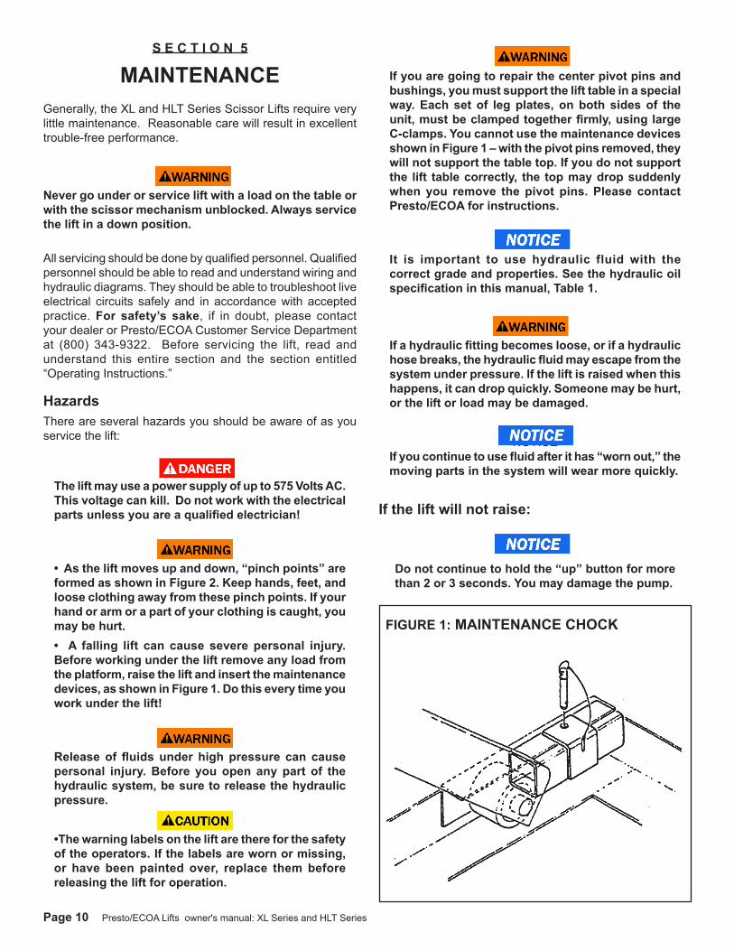
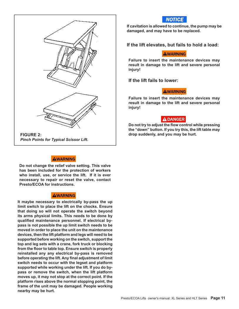
WARNINGS• As the lift moves up and down, “pinch points” are formed as shown in Figure 2. Keep hands, feet, and loose clothing away from these pinch points. If your hand or arm or a part of your clothing is caught, you may be hurt. • A falling lift can cause severe personal injury. Before working under the lift remove any load from the platform, raise the lift and insert the maintenance devices, as shown in Figure 1. Do this every time you work under the lift!
WARNINGSRelease of fluids under high pressure can cause personal injury. Before you open any part of the hydraulic system, be sure to release the hydraulic pressure.
CAUTION•The warning labels on the lift are there for the safety of the operators. If the labels are worn or missing, or have been painted over, replace them before releasing the lift for operation.
WARNING! If you are going to repair the center pivot pins and bushings, you must support the lift table in a special way. Each set of leg plates, on both sides of the unit, must be clamped together firmly, using large C-clamps. You cannot use the maintenance devices shown in Figure 1 – with the pivot pins removed, they will not support the table top. If you do not support the lift table correctly, the top may drop suddenly when you remove the pivot pins. Please contact Presto/ECOA for instructions.
NOTICE It is important to use hydraulic fluid with the correct grade and properties. See the hydraulic oil specification in this manual, Table 1.
WARNING!If a hydraulic fitting becomes loose, or if a hydraulic hose breaks, the hydraulic fluid may escape from the system under pressure. If the lift is raised when this happens, it can drop quickly. Someone may be hurt, or the lift or load may be damaged.
NOTICE If you continue to use fluid after it has “worn out,” the moving parts in the system will wear more quickly.
If the lift will not raise:
NOTICE Do not continue to hold the “up” button for more than 2 or 3 seconds. You may damage the pump.
FIGURE 1: MAINTENANCE CHOCK
Presto/ECOA Lifts owner's manual: XL Series and HLT Series Page 11
WARNING! Do not change the relief valve setting. This valve has been included for the protection of workers who install, use, or service the lift. If it is ever necessary to repair or reset the valve, contact Presto/ECOA for instructions.
WARNING!It maybe necessary to electrically by-pass the up limit switch to place the lift on the chocks. Ensure that doing so will not operate the switch beyond its arms physical limits. This needs to be done by qualified maintenance personnel. If electrical by-pass is not possible the up limit switch needs to be moved in order to place the unit on the maintenance devices, then the lift platform and legs will need to be supported before working on the switch, support the top and leg sets with a crane, fork truck or blocking from the floor to table top. Ensure switch is properly reinstalled any any electrical by-pass is removed before operating the lift. Any final adjustment of limit switch needs to occur with the legset and platform supported while working under the lift. If you do by-pass or remove the switch, when the lift platform moves up, it may not stop at the correct point. If the platform rises above the normal stopping point, the frame of the unit may be damaged. People working nearby may be hurt.
NOTICEIf cavitation is allowed to continue, the pump may be damaged, and may have to be replaced.
If the lift elevates, but fails to hold a load:
WARNING! Failure to insert the maintenance devices may result in damage to the lift and severe personal injury!
If the lift fails to lower:
WARNING! Failure to insert the maintenance devices may result in damage to the lift and severe personal injury!
DANGER! Do not try to adjust the flow control while pressing the “down” button. If you try this, the lift table may drop suddenly, and you may be hurt. FIGURE 2:
Pinch Points for Typical Scissor Lift.
Page 12 Presto/ECOA Lifts owner's manual: XL Series and HLT Series
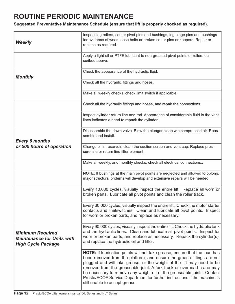
WeeklyInspect leg rollers, center pivot pins and bushings, leg hinge pins and bushings for evidence of wear. loose bolts or broken cotter pins or keepers. Repair or replace as required.
Monthly
Apply a light oil or PTFE lubricant to non-greased pivot points or rollers de-scribed above.
Check the appearance of the hydraulic fluid.
Check all the hydraulic fittings and hoses.
Make all weekly checks, check limit switch if applicable.
Every 6 monthsor 500 hours of operation
Check all the hydraulic fittings and hoses, and repair the connections.
Inspect cylinder return line and rod. Appearance of considerable fluid in the vent lines indicates a need to repack the cylinder.
Disassemble the down valve. Blow the plunger clean wih compressed air. Reas-semble and install.
Change oil in reservoir, clean the suction screen and vent cap. Replace pres-sure line or return line filter element.
Make all weekly, and monthly checks, check all electrical connections..
NOTE: If bushings at the main pivot points are neglected and allowed to oblong, major structural prolems will develop and extensive repairs will be needed.
Minimum Required Maintenance for Units with High Cycle Package
Every 10,000 cycles, visually inspect the entire lift. Replace all worn or broken parts. Lubricate all pivot points and clean the roller track.
Every 30,000 cycles, visually inspect the entire lift. Check the motor starter contacts and limitswitches. Clean and lubricate all pivot points. Inspect for worn or broken parts, and replace as necessary.
Every 90,000 cycles, visually inspect the entire lift. Check the hydraulic tank and the hydraulic lines. Clean and lubricate all pivot points. Inspect for worn or broken parts, and replace as necessary. Repack the cylinder(s), and replace the hydraulic oil and filter.
NOTE: If lubrication points will not take grease, ensure that the load has been removed from the platform, and ensure the grease fittings are not plugged and will take grease, or the weight of the lift may need to be removed from the greaseable joint. A fork truck or overhead crane may be necessary to remove any weight off of the greaseable joints. Contact Presto/ECOA Service Department for further instructions if the machine is still unable to accept grease.
ROUTINE PERIODIC MAINTENANCESuggested Preventative Maintenance Schedule (ensure that lift is properly chocked as required).
Presto/ECOA Lifts owner's manual: XL Series and HLT Series Page 13
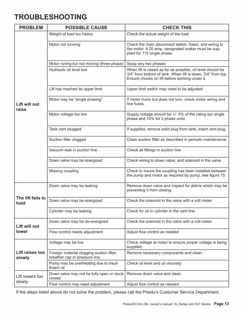
PROBLEM POSSIBLE CAUSE CHECK THIS
Lift will not raise
Weight of load too heavy Check the actual weight of the load
Motor not running Check the main disconnect switch, fuses, and wiring to the motor. A 20 amp, designated braker must be sup-plied for 115 single phase.
Motor runing but not moving (three phase) Swap any two phasesHydraulic oil level low When lift is raised as far as possible, oil level should be
3/4” from bottom of tank. When lift is down, 3/4” from top. Ensure chocks on lift before working under it.
Lift has reached its upper limit Upper limit switch may need to be adjusted
Motor may be “single phasing” If motor hums but does not turn, check motor wiring and line fuses.
Motor voltage too low Supply voltage should be +/- 5% of the rating aor single phase and 10% for 3 phase units.
Tank vent plugged If supplied, remove solid plug from tank, insert vent plug.
Suction filter clogged Clean suction filter as described in periodic maintenance
Vacuum leak in suction line Check all fittings in suction line
Down valve may be energized Check wiring to down valve, and solenoid in the valve
Missing coupling Check to insure the coupling has been installed between the pump and motor as required by pump, see figure 15.
The lift fails to hold
Down valve may be leaking Remove down valve and inspect for debris which may be preventing it from closing.
Down valve may be energized Check the solenoid in the valve with a volt meter.
Cylinder may be leaking Check for oil in cylinder in the vent line.
Lift will not lower
Down valve may be de-energized Check the solenoid in the valve with a volt meter
Flow control needs adjustment Adjust flow control as needed
Lift raises too slowly
Voltage may be low Check voltage at motor to ensure proper voltage is being supplied
Foreign material clogging suction filter, breather cap or pressure line
Remove necessary components and clean
Pump may be overheating due to insuf-ficient oil
Check oil level and oil viscosity
Lift lowers too slowly
Down valve may not be fully open or stuck closed
Remove down valve and clean
Flow control may need adjustment Adjust flow control as needed
If the steps listed above do not solve the problem, please call the Presto’s Customer Service Department.
TROUBLESHOOTING
Page 14 Presto/ECOA Lifts owner's manual: XL Series and HLT Series
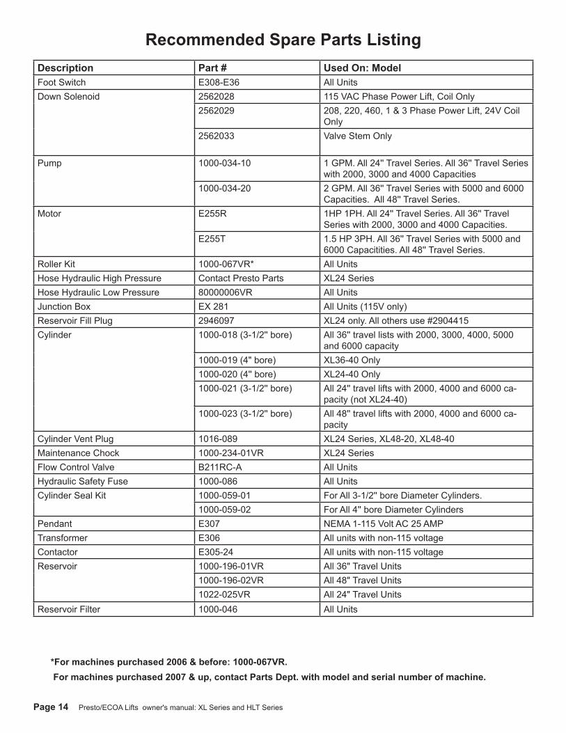
*For machines purchased 2006 & before: 1000-067VR. For machines purchased 2007 & up, contact Parts Dept. with model and serial number of machine.
Description Part # Used On: ModelFoot Switch E308-E36 All UnitsDown Solenoid 2562028 115 VAC Phase Power Lift, Coil Only
2562029 208, 220, 460, 1 & 3 Phase Power Lift, 24V Coil Only
2562033 Valve Stem Only
Pump 1000-034-10 1 GPM. All 24'' Travel Series. All 36'' Travel Series with 2000, 3000 and 4000 Capacities
1000-034-20 2 GPM. All 36'' Travel Series with 5000 and 6000 Capacities. All 48'' Travel Series.
Motor E255R 1HP 1PH. All 24'' Travel Series. All 36'' Travel Series with 2000, 3000 and 4000 Capacities.
E255T 1.5 HP 3PH. All 36'' Travel Series with 5000 and 6000 Capacitities. All 48'' Travel Series.
Roller Kit 1000-067VR* All UnitsHose Hydraulic High Pressure Contact Presto Parts XL24 SeriesHose Hydraulic Low Pressure 80000006VR All UnitsJunction Box EX 281 All Units (115V only)Reservoir Fill Plug 2946097 XL24 only. All others use #2904415Cylinder 1000-018 (3-1/2'' bore) All 36'' travel lists with 2000, 3000, 4000, 5000
and 6000 capacity1000-019 (4" bore) XL36-40 Only1000-020 (4'' bore) XL24-40 Only1000-021 (3-1/2'' bore) All 24'' travel lifts with 2000, 4000 and 6000 ca-
pacity (not XL24-40)1000-023 (3-1/2'' bore) All 48'' travel lifts with 2000, 4000 and 6000 ca-
pacityCylinder Vent Plug 1016-089 XL24 Series, XL48-20, XL48-40Maintenance Chock 1000-234-01VR XL24 SeriesFlow Control Valve B211RC-A All UnitsHydraulic Safety Fuse 1000-086 All UnitsCylinder Seal Kit 1000-059-01 For All 3-1/2'' bore Diameter Cylinders.
1000-059-02 For All 4'' bore Diameter CylindersPendant E307 NEMA 1-115 Volt AC 25 AMPTransformer E306 All units with non-115 voltageContactor E305-24 All units with non-115 voltageReservoir 1000-196-01VR All 36" Travel Units
1000-196-02VR All 48" Travel Units1022-025VR All 24" Travel Units
Reservoir Filter 1000-046 All Units
Recommended Spare Parts Listing
Presto/ECOA Lifts owner's manual: XL Series and HLT Series Page 15
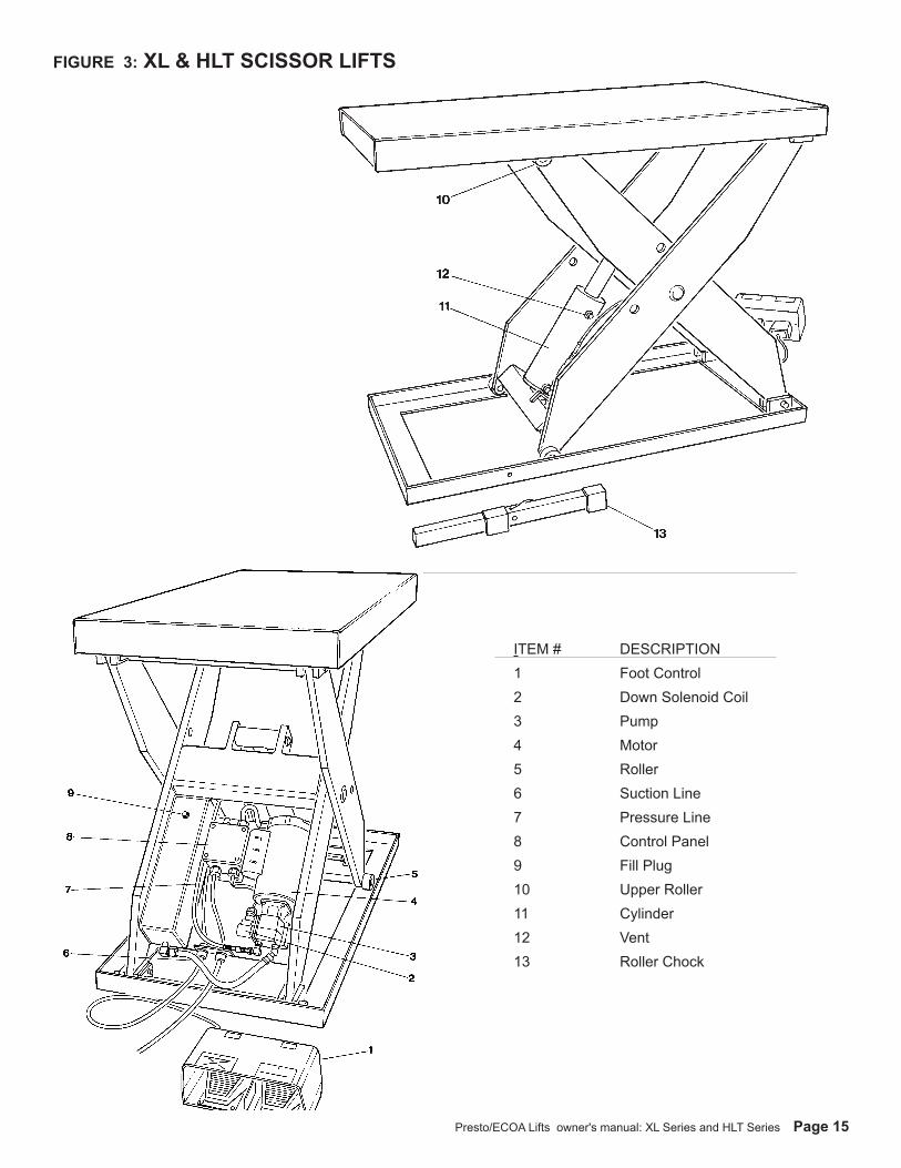
FIGURE 3: XL & HLT SCISSOR LIFTS
ITEM # DESCRIPTION1 Foot Control2 Down Solenoid Coil3 Pump4 Motor5 Roller6 Suction Line7 Pressure Line8 Control Panel9 Fill Plug10 Upper Roller11 Cylinder12 Vent13 Roller Chock
Page 16 Presto/ECOA Lifts owner's manual: XL Series and HLT Series
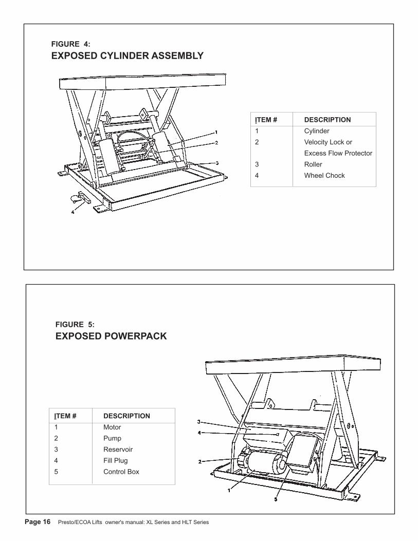
FIGURE 5: EXPOSED POWERPACK
FIGURE 4: EXPOSED CYLINDER ASSEMBLY
ITEM # DESCRIPTION1 Motor2 Pump3 Reservoir4 Fill Plug5 Control Box
ITEM # DESCRIPTION1 Cylinder2 Velocity Lock or Excess Flow Protector3 Roller4 Wheel Chock
Presto/ECOA Lifts owner's manual: XL Series and HLT Series Page 17
96"
PLA
TFO
RM
66"
BA
SE
24"
BASE
27"
LAG
S
48"
PLA
TFO
RM
64"
LA
GS
3/
4" L
AG
S
8"
48"
56"
HIN
GED
EN
D
5
1
4
8
67
?
2
NEM
A T
YPE
4 HA
ND
HELD
PUSH
BUTT
ON
W/
10' O
F C
ORD
NEM
A T
YPE
12 C
ON
TRO
LPA
NEL
SHI
PPED
LO
OSE
GEN
ERA
L DE
SCRI
PTIO
N:
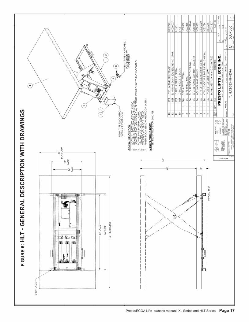
CA
PAC
ITY: 6
,500
LBM
UN
IFO
RM L
OA
D.
1.EL
EVA
TING
TIM
E: A
PPRO
X. 2
7 SE
CO
ND
S.2.
LOW
ERIN
G T
IME:
AD
JUST
ABL
E W
/ PR
ESSU
RE C
OM
PEN
SATE
D F
LOW
CO
NTR
OL.
3.PO
WER
UN
IT: IN
TERN
AL
3.2
HP.
4.PR
IMA
RY V
OLT
AG
E: 4
60/3
/60.
5.C
ON
TRO
L V
OLT
AG
E: 1
15/1
/60.
6.FI
NIS
H: E
CO
A Y
ELLO
W A
ND
EC
OA
LA
BELS
.7. M
AN
UFA
CTU
RIN
G N
OTE
S:SE
T RE
LIEF
VA
LVE
FOR
2400
PSI
.1.
ITEM
N
O.
QTY
.U/
MD
ESC
RIPT
ION
PART
NO
.
13
REF
HY P
LUM
BIN
G S
CHE
MA
TIC80
0029
0112
RE
FEL
WIR
ING
DIA
G 2
08/2
30/4
60 A
C X
FMR
8000
0027
11
REF
LD D
CL
5.21
X3.5
0 EC
OA
L-15
510
RE
FLD
DC
L 8.
00X5
.12
ECO
AL-
429
1G
AL
CPC
SHW
YEL
EC
OA
1008
5871
81
EAEL
PB
HHEL
D N
4X30
0385
67
1EA
EL O
LRE
SPRS
CH
CT7
N-2
3-B4
810
0551
606
1EA
EL C
TRL
PAN
EL 2
30/4
60 1
15A
C N
1230
5021
65
1EA
AC
L LA
G A
NG
KIT
UNIV
3008
952
41
EATP
PF
LIFT
48.
00X9
6.00
STR
LS6
-48
6002
6022
31
EAHY
PU
I 230
V 3
P 3.
2HP
2.8G
PM 2
.4UG
AL
3032
734
21
EAHY
ARR
I LS
6-48
3P
24W
3004
575
11
EABA
B&
L A
SSY
LSX-
48 6
10.0
0X16
77.0
060
0213
27
CD B A
43
21
D C B A
31
24
SHEE
T 1 O
F 1
DW
G N
O 5007
386
50 C
omm
erce
Way
Nor
ton
MA
027
66
STATUS:Released
3RD
AN
GLE
PRO
JEC
TION
TL H
LT2-
065-
48-4
8096
LS6-
48
8
4438
243
1208
.53
LB
-50
0738
6RE
VD
WG
. N
O.
C SIZE
TITLE
:
FRA
CTIO
NS
1
/.X
XX
.005
.XX
.01
AN
GLE
S:
.5
USE
OF
PRO
PRIE
TARY
INFO
RMA
TION
LIM
ITED
TO
WRI
TTEN
AG
REEM
ENT
SCA
LEW
TRE
FERE
NC
EC
AG
E C
OD
E06
3Z8
UNLE
SS O
THER
WIS
ESP
ECIF
IED
.D
IMEN
SIO
NS
ARE
ININ
CHE
S
SHEE
T 1 O
F 1
DR
CK
1:1
2
PR
ES
TO
LIF
TS
/ E
CO
A I
NC
.12
/05/
16D
ATE
DA
TE
BCH
MO
DEL
B377
41PR
OJE
CT:
v.14
TH
IS D
RA
WIN
G M
UST
BE
AT
RE
VIS
ION
: '-'
FIG
UR
E 6:
HLT
- G
ENER
AL
DES
CR
IPTI
ON
WIT
H D
RAW
ING
S
Page 18 Presto/ECOA Lifts owner's manual: XL Series and HLT Series
FIGURE 7: WIRING SCHEMATIC 115/1/60 power with 20 AMP PLUG
Presto/ECOA Lifts owner's manual: XL Series and HLT Series Page 19
FIGURE 8: WIRING SCHEMATIC 208, 220, 460/3/60 POWER with PIG TAIL
Page 20 Presto/ECOA Lifts owner's manual: XL Series and HLT Series
FIG
UR
E 9
: H
YDR
AU
LIC
SC
HEM
ATIC
for a
ll M
OD
ELS
Presto/ECOA Lifts owner's manual: XL Series and HLT Series Page 21
FIG
UR
E 1
0:
LAB
ELIN
G D
IAG
RA
M fo
r all
MO
DEL
S

Page 22 Presto/ECOA Lifts owner's manual: XL Series and HLT Series
FIGURE 11: WIRING DIAGONAL 115 AC NO TRANSFORMER
Presto/ECOA Lifts owner's manual: XL Series and HLT Series Page 23
FIGURE 12: PLUMBING SCHEMATIC
Page 24 Presto/ECOA Lifts owner's manual: XL Series and HLT Series
PARTSStandard parts may be returned with a 20% restocking fee or $35.00 net, whichever is greater. Modified or custom-engineered parts are not returnable. Unfortunately, due to potentially concealed damage, all sales of electrical assemblies are final.
QUALITY ISSUESShould you feel there is a quality problem, please contact the seller to ask questions and gather information on how to rectify the issue. Presto/ECOA Lifts reserves the right to determine potential credits, as a result of factory defects, based on its inspection of the merchandise.
GENERALAll products shipped from our factory have passed Quality Assurance inspection and testing. The carrier of choice has signed for, and accepted the product in new working condition. The customer should inspect to ensure it is not received damaged, has no concealed damage or is not incomplete. Parts orders are determined to be complete based upon Presto Lift, Inc. inspection sheets and carrier shipping weights.
Presto/ECOA Lifts owner's manual: XL Series and HLT Series Page 25
Ordering Replacement Parts
Presto/ECOA Lifts has carefully chosen the components in your unit to be the best available for the purpose. Replacement parts should be identical to the original equipment. Presto/ECOA Lifts will not be responsible for equipment failures resulting from the use of incorrect replacement parts or from unauthorized modifications to the unit.
Presto/ECOA Lifts can supply all replacement parts for your lift. With your order, please include the model number and the serial number of the unit. You can find these numbers on the name plate. This plate is located within the scissors mechanism.
To order replacement parts, please call the Presto/ECOA Lifts Parts Department. Parts are shipped subject to the following terms:
• FOB factory• Returns only with the approval of our parts department.• Credit cards preferred (except parts covered by warranty).• Freight collect for truck (except parts covered by warranty).• Freight – prepaid and invoice for small parcel shipments (except parts covered by warranty).• The warranty for repair parts is 30 days from date of shipment.
Parts replaced under warranty are on a “charge-credit” basis. We will invoice you when we ship the replacement part, then credit you when you return the worn or damaged part, and we verify that it is covered by our warranty. Labor is not covered under warranty for Parts orders.
Presto/ECOA Parts Department50 Commerce WayNorton, MA 02766
Telephone: 800-343-9322FAX: 888-788-6496
Email: [email protected]

Page 26 Presto/ECOA Lifts owner's manual: XL Series and HLT Series
Presto and ECOA LiftsLimited Warranty Policy
Presto and ECOA Lifts warrants all of its products against defects in the welded structural frame and, if applicable, scissor legs from faulty material and workmanship for a period of five years from the date of invoice.
All other components have a limited warranty against defects in faulty material and workman-ship for a two year period from the date of invoice date of invoice and 30 day limited warranty on labor. Please note that prior authorization from Presto and ECOA Lifts is required on all warranty work.
There are no implied warranties of any kind, more specifically, there are no warranties of mer-chantability or fitness for any particular purpose. Presto and ECOA Lifts' sole warranty shall be as set forth in this limited warranty.
Presto and ECOA Lifts will elect to repair or replace a defective component without charge, if any components should become defective within the limited warranty period. Proof of purchase is required for warranty. The charge for shipping the defective component is the responsibility of the buyer and must be accompanied with an RMA number. The shipping charge to return the component to the buyer is the responsibility of Presto and ECOA Lifts.
This limited warranty does not cover labor expense for removal or reinstallation of components after thirty days. This limited warranty shall not cover, among other things: damages result-ing from foreign matter or water, failure to provide reasonable and necessary maintenance, and if applicable, use of product while charger is plugged into an AC outlet, or failure to follow operating instructions. The limited warranty is not valid for damage resulting from negligence, accident, unreasonable use, abuse or misuse, exceeding data plate capacities or altering the product without Presto and ECOA Lifts authorization.
Presto and ECOA Lifts expressly disclaims and excludes any liability for consequential, inci-dental, indirect or punitive damages or financial loss to people or property resulting from any breach of warranty or the operation or failure of this product.
Presto and ECOA Lifts makes no representation that this product complies with local, state, or federal safety/product standards codes. Should this product fail to comply in any way with those codes, it shall not be considered a defect of materials or workmanship. Presto Lifts shall not be held liable for any damages resulting from noncompliance. It is the dealer's responsibil-ity to exercise this limited warranty. This limited warranty is provided to the original purchaser (defined as the original end user) and is nontransferable. This constitutes the complete and final agreement involving Presto Lifts and ECOA Lifts limited warranty obligations for products.
Recommended