
Process flow and gathering system
Session VI
Elín Hallgrímsdóttir and Lilja Tryggvadóttir
Mannvit Strasbourg, Nov.8, 2012

Presentation overview
• Presentations reviewing different work cycles
• Main concept of the gathering system
• Calculated example showing methods used within geothermal steam gathering system design


Geothermal in Iceland

Process flow
• A review of thermodynamic cycles used in geothermal energy production with emphasis on electricity generation
• Flash steam cycles with single flash and double flash as well as different binary cycles as ORC and Kalina Cycle are introduced and compared

Back Pressure Steam Power Plant
Steam separator
Turbine Generator
G
Production wells Reinjection wells
Phigh
Plow
2 phase flow Vapor
Liquid

Back pressure unit - layout Separator
Machine Hall
Electrical cabinets & Control room
Asphalted area for installation and maintenance purposes

0
100
200
300
400
500
600
700
00,20,40,60,811,2
Turb
ine
Po
we
r [k
J/kg
]
Turbine outlet pressure [bara]
Calculated examples Different turbine outlet pressure

G
Production wells
Geothermal fluid
Steam separator
Turbine
Condenser
Steam Generator
Silencer
Mist eliminator
Water
Condensate
Condensate
Cooling tower
Reinjection wells
Gas Extraction System
Steam Power Plant with Condenser


Steam Power Plant – Double Pressure
G
Production wells
Two phase flow Turbine - generator HP steam
LP steam
Reinjection wells
Condenser Tcw
Cooling system
Steam separator
LP Steam separator
Two phase flow

Svartsengi – the“Octopus”

Steam Power Plant – Double Flash
Production wells Reinjection wells
G
Steam supply system Turbine - generator Primary steam
Secondary steam
Condenser Tcw
Cooling system
G
LP Turbine - generator
Tcw
Cooling system
Steam separator
LP Steam separator

Hellisheiði – low pressure unit

Steam Power Plant w. District Heating
G
Production wells
Steam supply system Turbine - generator Primary steam
Reinjection wells
Condenser
Tcw
Cooling system
Steam separator
District heating system
Freshwater wells
To district heating

District heating plant

25. 02. 2008
Production wells
Two phase flow
Steam separators
Geothermal water
Steam
Well head silencers
Re-injection wells
Pressure
regulation
Geothermal water
emergency exhaust
Turbines
Generators
Mist separators
Cooling
towers
Hot water tank
Cold water pump
Condensers
Heat exchangers
De-aerators
De-aerators
Condensers
Process Flow Diagram

G Tsource
Tdischarge
Phigh
Plow
Condenser
Turbine Generator
Circulation pump
Evaporator
Tcw
Cooling system
Binary Cycles

G Tsource
Tdischarge
Phigh
Plow
Tcw Condenser
Turbine Generator
Circulation pump
Evaporator
Recuperator
Cooling system
Binary Cycles – with Recuperation

Binary Plant Berlin – El Salvador LaGeo

G
Separator
High temp recuperator
Low temp recuperator
Condenser
Evaporator
Turbine Generator
Tsource
Tdischarge
Tcw
Circulation pump
Cooling system
Binary Cycles – Kalina

Húsavik Kalina plant

2 0 02 5 03 0 03 5 04 0 04 5 05 0 05 5 0
2 0
4 0
6 0
8 0
1 0 0
1 2 0
1 4 0
Heat transfer
Tem
pera
ture
0 0 , 2 0 , 4 0 , 6 0 , 8 1
5 0
6 0
7 0
8 0
9 0
1 0 0
1 1 0
1 2 0
Heat Transfer
Te
mp
era
ture
ORC Kalina

G
Tsource
Tdischarge
Cooling system
Binary Cycles – Kalex

Work Cycle Comparison Specific Power

0
2
4
6
8
10
12
80 85 90 95 100 105 110 115 120 125 130
€/W
Inlet Temperature [°C]
Kalina
Kalex
ORC
Work Cycle Cost Comparison

G
G
G
Steam supply system Turbine - generator
Primary binary turbine - generator
Evaporator
Secondary binary turbine - generator
Cooling system
Cooling system
Production wells Reinjection wells
Demonstration of model
• Turboden ORC model: http://www.turboden.eu/en/rankine/rankine-calculator.php

Gathering System
• This session will present an overview of the design process of a geothermal gathering system with emphasis on particularities of the geothermal fluid.

Two phase flow
Steam separators
Geothermal
water
Steam
Re-injection wells
Pressure
relief Production wells
Turbines
Generators
Mist separators
Cooling
towers
Condensers
Steam Supply - Preliminary P&ID
emergency exhaust

Nesjavellir Power Plant
Separation
station
Steam vent
station
Steam
pipelines
Two phase
flow
Power
Plant
Production
Well
Cooling towers

Gathering system- Design
• Design standards
• Standards i.e. Pressure directive 97/23/EC
• Pressure selection • Chemical constraints
• Power generation
• Productivity curves
0
200
400
600
800
1000
1200
1400
1.00 10.00 100.00
SiO
2(m
g/k
g)
Pressure (bar-a)
quartz solubility (F&P82)
amorphous silica solubility (F77)
330 °C
300 °C
270 °C
240 °C
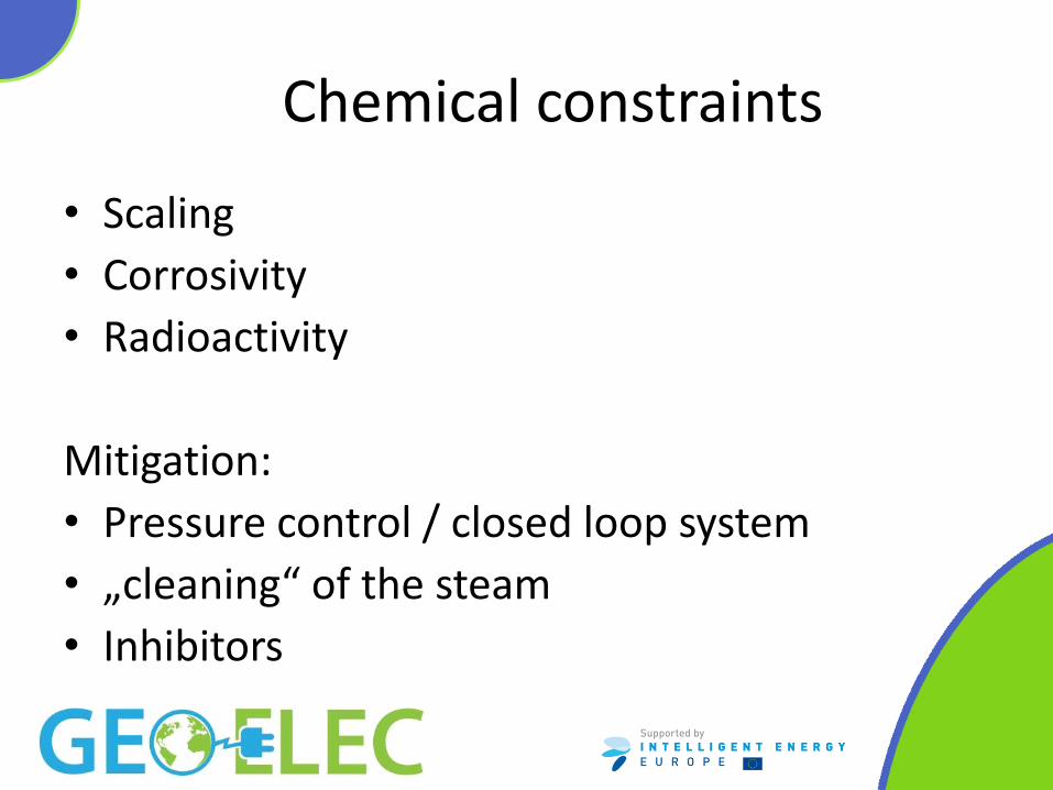
Chemical constraints
• Scaling
• Corrosivity
• Radioactivity
Mitigation:
• Pressure control / closed loop system
• „cleaning“ of the steam
• Inhibitors

h = 1600 kJ/kg
h = 1800 kJ/kg
h = 2000 kJ/kg
h = 2200 kJ/kg
0
50
100
150
200
250
300
350
400
450
500
0 2 4 6 8 10 12 14 16 18 20
Turb
ine
po
we
r [k
J/kg
]
Separator pressure [bara]
Assumptions: Total turbine efficiency: 0,8
Power generation

Typical productivity curves

Well Pump – Low Enthalpy
• Type
• Submersible pump
• Line shaft pump
• Selection and operation
• Depth
• Temperature
• Scaling
• Bubble point

Gathering System– Design load
• Constant load – Weight – Pressure
• Variable load (depending on location) – Wind load – Snow load – Earthquake
• Frictional load – Thermal expansion – Friction

Gathering System - Pipelines
• Pipe laying
• Under ground
• Above ground
• Material selection
• Pipe size
• Pressure/temperature

Steam Supply System – Pipelines
300
400
500
600
700
800
900
1000
0 20 40 60 80 100 120 140 160
Pip
e d
iam
ete
r [m
m]
Flow [kg/s]
7 bar-a
20 bar-a

Gathering system – route selection
• Public safety
• Environmental impact
• Restriction on land
• Cost efficiency
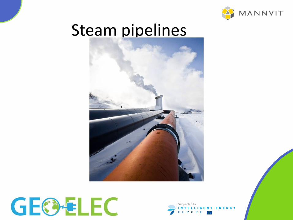
Steam pipelines

Steam Supply - Layout
• Central separation station
• Satellite separation stations
• Individual separators
Central Satellite Individual

Power plant layout


Steam Supply - Separators
• Cyclone separators
• Gravity separators
• Efficiency
• Steam separator and moisture separator should together achieve 99,99 % bw. liquid removal or better

Calculated example
• The presenter will go through a calculated example to show methods used for basic engineering within steam gathering system design. The example taken will be connected to the special conditions encountered in geothermal energy.

Example • Example for 1200 kJ/kg well enthalpy
– 40-50°C condensing temperature
– Back pressure
• Objective
– Maximize the power production
• Assumptions
– We know the reservoir enthalpy
– We know the condenser temperature
– Separation pressure does not influence the well flow

Example, condensing unit

Example, condensing unit
• The maximum power will be 12,4 MW
– Entalpy = 1200 kJ/kg
– Condensing pressure 0,075 bara / temperature 40°C
– Separation pressure 6 bara
– Flow 100 kg/s
• What if we selected backpressure instead?

Example, back pressure

Example, back pressure
• The maximum power will be 6,4 MW
– Entalpy = 1200 kJ/kg
– Separation pressure 12 bara
– Flow 100 kg/s

Example
• Optimum separation pressure is 6 bara, is that ok?
• Saturation temperature for 1200 kJ/kg is 273°C
0
200
400
600
800
1000
1200
1400
1.00 10.00 100.00
SiO
2(m
g/k
g)
Pressure (bar-a)
quartz solubility (F&P82)
amorphous silica solubility (F77)
330 °C
300 °C
270 °C
240 °C

Thank You! VISIT GEOELEC.EU
Recommended