MANUAL: - M3
HORIZONTAL MONO BLOCK METALLIC PUMP
(GROUP- 0 & I)
INSTALLATION,
OPERATION AND MAINTENANCE
MANUAL
PROCESS PUMPS (INDIA) PVT LTD Plot No.86, III Phase, Peenya Industrial Area, Bangalore – 560058
Phone: 91-80-28395327/28
Fax: 91-80-28395807
WEBSITE: www.process-pumps.com
E-mail: [email protected]

HORIZONTAL MONO BLOCK METALLIC PUMP
(GROUP – 0 & I )
2
CONTENTS
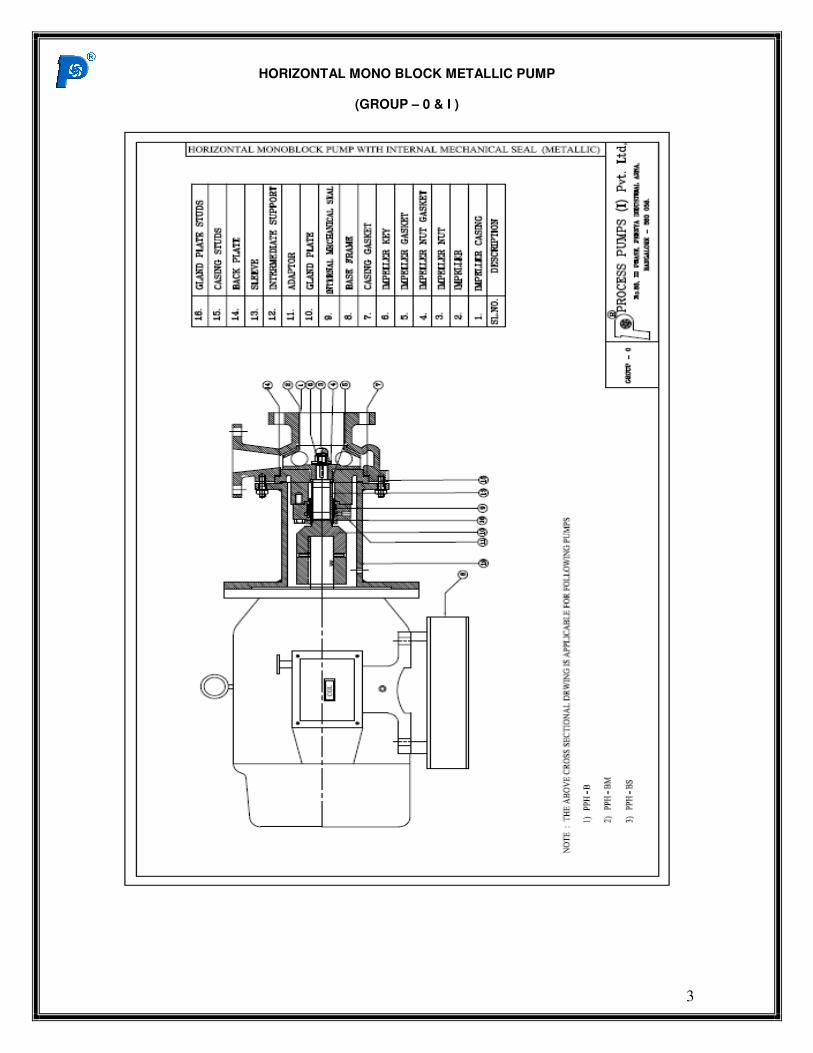
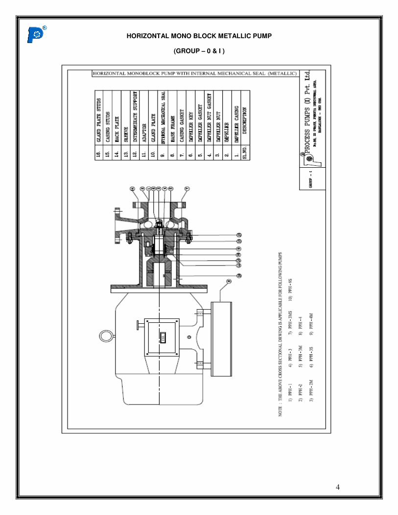
� CROSS SECTIONAL DRAWINGS AND SPARES DETAILS WITH “INTERNAL
MECHANICAL SEAL”
� DETAILS OF BEARINGS, OIL SEALS ‘O’ RINGS AND SHAFT SLEEVS
1.0 INTRODUCTION
2.0 SCOPE OF SUPPLY
3.0 STORAGE AND HANDLING
3.1 RECEIVING THE MATERIAL
4.0 ERECTION
4.1 FOUNDATION
5.0 PIPE WORK INSTALLATION
5.1 SUCTION CONDITION
5.2 AUXILLARY PIPE CONNECTION
6.0 STARTING THE PUMP
6.1 PRE START CHECK UP
6.2 PRIMING
7.0 OPERATION OF THE PUMP
8.0 CORROSION
9.0 STOPPING THE PUMP
10.0 DIRECTION OF ROTATION
11.0 MAINTENANCE
11.1 INTERNAL MECHANICAL SEAL
12.0 REVERSE ROTATION
13.0 ROUTINE MAINTENANCE SCHEDULE
14.0 TROUBLE SHOOTING
15.0 MAINTENANCE PRACTICE
DOC.NO:PPIL/HM/M/G-0&I/IMS-R-01 DATE: 12.12.2014
HORIZONTAL MONO BLOCK METALLIC PUMP
(GROUP – 0 & I )
3
HORIZONTAL MONO BLOCK METALLIC PUMP
(GROUP – 0 & I )
4
HORIZONTAL MONO BLOCK METALLIC PUMP
(GROUP – 0 & I )
5
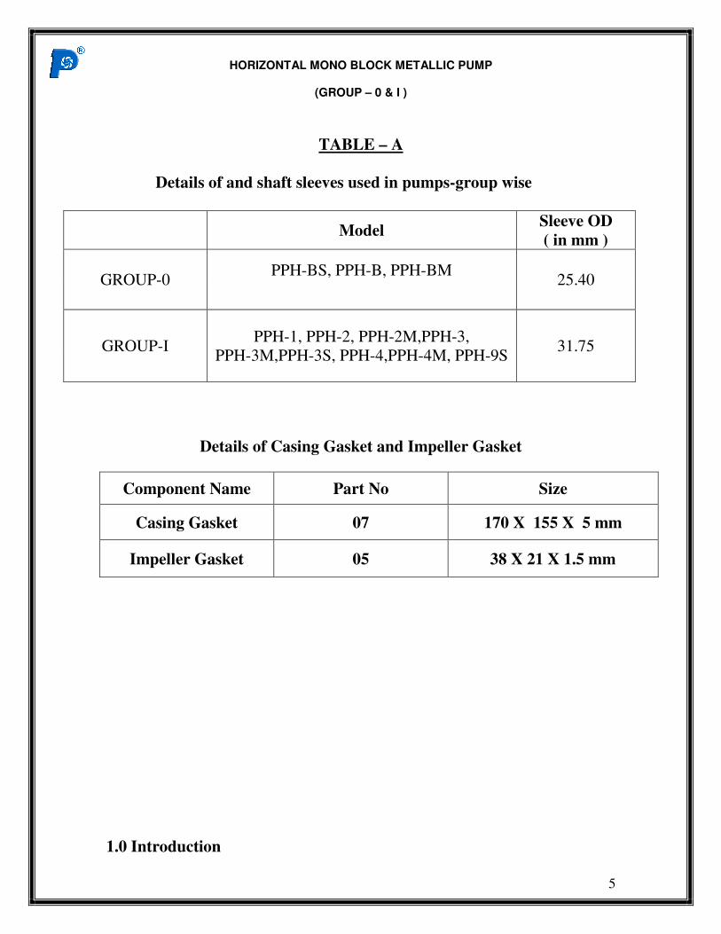
TABLE – A
Details of and shaft sleeves used in pumps-group wise
Model Sleeve OD
( in mm )
GROUP-0 PPH-BS, PPH-B, PPH-BM
25.40
GROUP-I PPH-1, PPH-2, PPH-2M,PPH-3,
PPH-3M,PPH-3S, PPH-4,PPH-4M, PPH-9S 31.75
Details of Casing Gasket and Impeller Gasket
Component Name Part No Size
Casing Gasket 07 170 X 155 X 5 mm
Impeller Gasket 05 38 X 21 X 1.5 mm
1.0 Introduction
HORIZONTAL MONO BLOCK METALLIC PUMP
(GROUP – 0 & I )
6
The Mono block series pump is a horizontal, single stage; end suction
centrifugal pump fitted with either a closed or semi open impeller. For
handling clear liquids a closed impeller is used whereas for handling liquids
containing solids a semi open impeller is preferred. The pumps are designed
to ISO 2858 standard . The drive from the electric Motor is transmitted to
the pump through an Adaptor.
2.0 Scope of Supply
The pump is supplied with the following accessories as a standard
practice.
a) Mechanical seal or Gland Packing
b) M.S. fabricated Base plate for Motor.
3.0 Storage & Handling
3.1 Receiving the Material
a) As soon as the material is received the packages should be checked from
the delivery challan to ensure that all the items are received and are
intact. Discrepancies, if any, must be immediately reported.
b) Packages should not be dropped and are to be handled carefully to avoid
damage to the pump and motor
c) The place of storage should be well ventilated but free from dust, heat
moisture.
HORIZONTAL MONO BLOCK METALLIC PUMP
(GROUP – 0 & I )
7
4.0 Erection
All external parts of pump and motor must be thoroughly cleaned
before erection begins.
4.1 Foundations
The pump assembly must be firmly mounted on the foundation bed
secured by means of foundation bolts. The foundation must be strong
enough to support the unit and dampen any vibration when the pump is in
operation (it is preferable to use a spirit level placed on cleaned machined
surface of the pump while erecting the pump). The level can be adjusted by
inserting steel packers between the bedplate and the foundation bolt
accompanied by a gentle tightening of the bolt and should be cemented prior
to erection.
5.0 Pipe work Installation
All piping should be supported by hangers or independent supports.
Care must be taken to ensure that no piping strains are transmitted to the
pump as this may cause misalignment.
HORIZONTAL MONO BLOCK METALLIC PUMP
(GROUP – 0 & I )
8
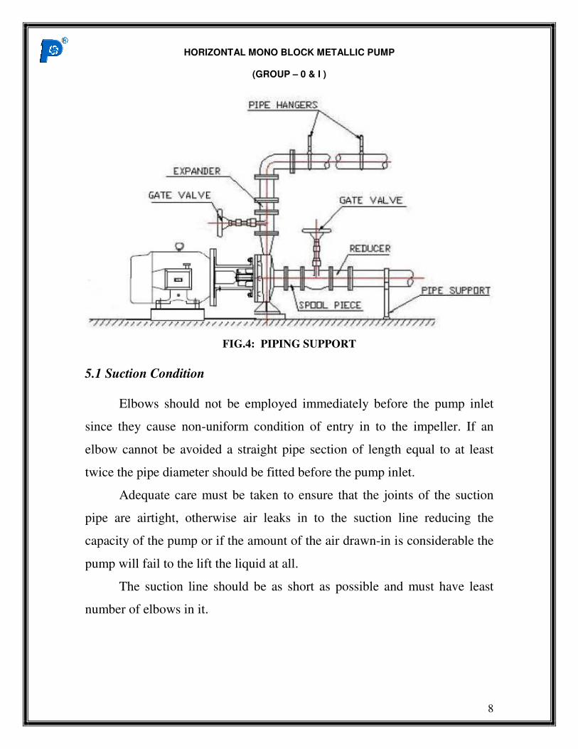
FIG.4: PIPING SUPPORT
5.1 Suction Condition
Elbows should not be employed immediately before the pump inlet
since they cause non-uniform condition of entry in to the impeller. If an
elbow cannot be avoided a straight pipe section of length equal to at least
twice the pipe diameter should be fitted before the pump inlet.
Adequate care must be taken to ensure that the joints of the suction
pipe are airtight, otherwise air leaks in to the suction line reducing the
capacity of the pump or if the amount of the air drawn-in is considerable the
pump will fail to the lift the liquid at all.
The suction line should be as short as possible and must have least
number of elbows in it.
HORIZONTAL MONO BLOCK METALLIC PUMP
(GROUP – 0 & I )
9
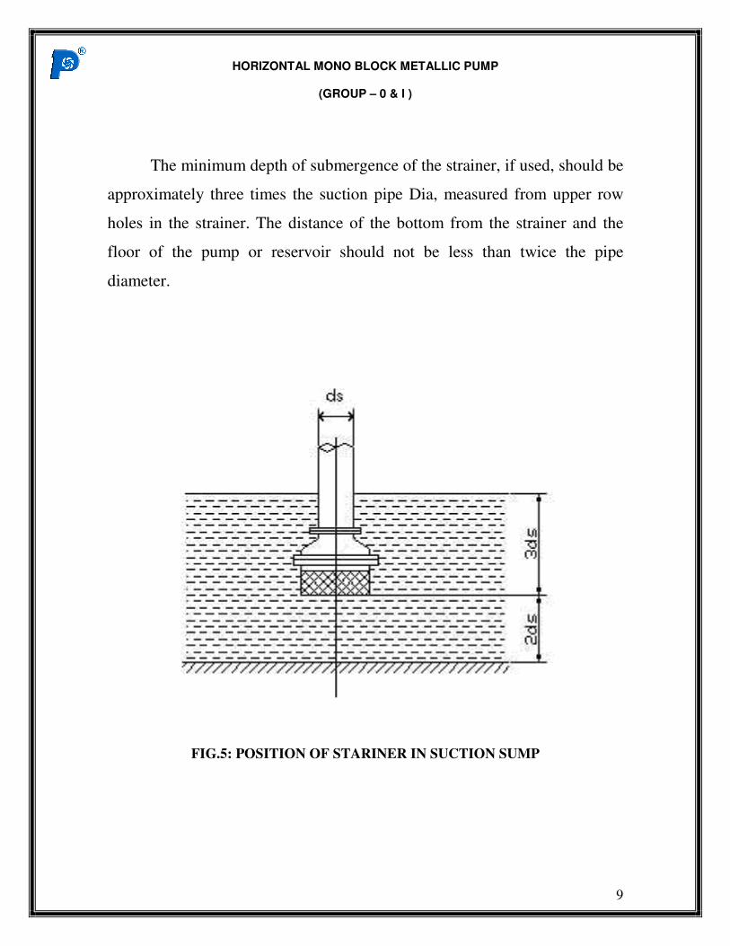
The minimum depth of submergence of the strainer, if used, should be
approximately three times the suction pipe Dia, measured from upper row
holes in the strainer. The distance of the bottom from the strainer and the
floor of the pump or reservoir should not be less than twice the pipe
diameter.
FIG.5: POSITION OF STARINER IN SUCTION SUMP
HORIZONTAL MONO BLOCK METALLIC PUMP
(GROUP – 0 & I )
10
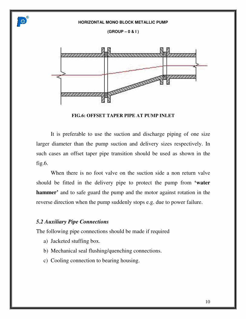
FIG.6: OFFSET TAPER PIPE AT PUMP INLET
It is preferable to use the suction and discharge piping of one size
larger diameter than the pump suction and delivery sizes respectively. In
such cases an offset taper pipe transition should be used as shown in the
fig.6.
When there is no foot valve on the suction side a non return valve
should be fitted in the delivery pipe to protect the pump from ‘water
hammer’ and to safe guard the pump and the motor against rotation in the
reverse direction when the pump suddenly stops e.g. due to power failure.
5.2 Auxiliary Pipe Connections
The following pipe connections should be made if required
a) Jacketed stuffing box.
b) Mechanical seal flushing/quenching connections.
c) Cooling connection to bearing housing.
HORIZONTAL MONO BLOCK METALLIC PUMP
(GROUP – 0 & I )
11
6.0 Starting the Pump
6.1 Pre Start Check
a) Wiring the motor terminals and starter should be checked. Direction of
rotation if incorrect must be corrected by reversing two of the starter
leads.
b) MECHANICAL SEALS: If pump is fitted with mechanical seal, the
manufacturer’s instructions are to be carried out.
6.2 Priming
The pump is filled with water or liquid through the priming funnel or
the delivery pipe. Priming can also be accomplished by employing a vacuum
pump to evacuate the air. Priming is not required for installations with
positive suction.
The delivery valve should be closed before starting the pump. On acid
service or organic liquid service the pump should not be run with the
delivery closed for more than a few seconds because the increase in the
temperature of acid or volatile liquid may be harmful.
The pressure indicated in the delivery gauge should go up steadily.
Otherwise it can be assumed that there is air in the pump. Should the
ammeter on the starter comeback almost to zero, it means that the pump has
lost its priming and in such cases repriming is a must.
HORIZONTAL MONO BLOCK METALLIC PUMP
(GROUP – 0 & I )
12
7.0 Operation of the Pump
The gland nuts should be tightened excessively in case of pumps with
gland packing. Liquid should not be allowed to leak from the stuffing box at
the rate of 30 to 60 drops per minute. This cools the shaft and reduces
friction. Packing should be replaced periodically when it gets worn away.
The desired capacity is to be set by throttling the discharge valve.
Observing the pressure gauge, ammeter, voltage and speed for satisfactory
suction conditions
The level of the oil in the bearings must be checked. The temperature
of the oil should not exceed 60 Deg C, above ambient temp. If the oil gets
darker the same should be replaced with fresh oil after flushing out the
bearing housing.
The drive end bearing cover is provided with six bolts altogether in
pumps above 250 mm impeller diameter. It can be seen that three of the
bolts are fully tightened to secure the bearing cover to the bearing housing
and the other three are left untightened. These three bolts are meant only for
adjusting the axial movement of the impeller and should never be mistaken
for untightened bolts.
HORIZONTAL MONO BLOCK METALLIC PUMP
(GROUP – 0 & I )
13
8.0 Corrosion
The material of construction of the pump has been selected after
careful study of the liquid to be handled, its composition, its corrosiveness,
specific gravity, pH, temp, solid content, particle size, viscosity, etc. A slight
variation in any of the above factor can cause severe corrosion of the wetted
parts. Therefore it is necessary that ample care be taken to ensure with every
fresh batch of liquid that its properties are the same for which the pump
originally is meant.
When numbers of pumps with different materials of construction have
been supplied for different duty conditions great care must be taken to
ensure that the right pump is put in to service.
Operating the pump at the point other than the specified duty point
might also have an adverse effect as far as the corrosion is concerned. Spare
parts of the same original material are to be used while parts are replaced to
avoid the formation of galvanic cell, which initiates corrosion.
9.0 Stopping the Pump
Before stopping the pump the discharge valve must be closed. The
motor is switched off and the sealing fluid to the gland / seal should be left
open in case of crystallizing liquid being pumped.
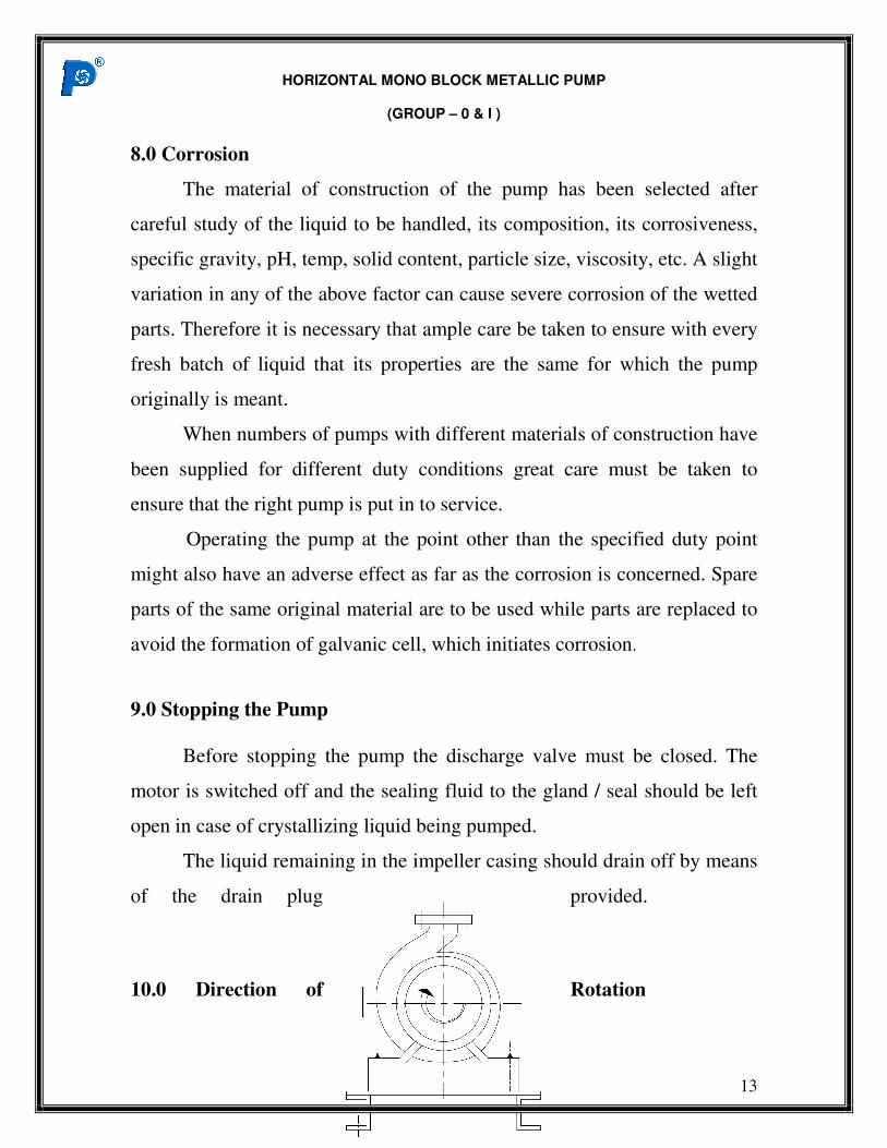
The liquid remaining in the impeller casing should drain off by means
of the drain plug provided.
10.0 Direction of Rotation
HORIZONTAL MONO BLOCK METALLIC PUMP
(GROUP – 0 & I )
14
FIG.7: VIEW FROM MOTOR SIDE
The pump should always be run in the direction indicated by the
arrow provided on the bearing housing. The pump has to rotate in the
“Clockwise Direction” when viewed from the motor fan side. While
checking the direction of the rotation the pump should be filled with liquid
in order to prevent it from running the packing or seal dry. Dry running of
the pump can cause immediate failure of the mechanical seal.
11.0 Maintenance
Depending on the operating conditions, the pump should be
dismantled and inspected at suitable intervals. Only experience can tell how
frequently these overhauls are necessary.
11.1 Internal Mechanical Seal
HORIZONTAL MONO BLOCK METALLIC PUMP
(GROUP – 0 & I )
15
Pumps with mechanical seal, care should be taken to fit the seals
exactly as per manufacturer’s instructions. Mechanical seal parts of Teflon
should be used for only one installation. Reusing of such parts is not
recommended.
12.0 Reverse rotation
When there is power cut to the pump driver clubbed with
malfunctioning of check valve at the discharge line. Subsequent to the power
cut, the pump speed reduces very rapidly causing rapid reduction in flow
arriving to a point where no flow could be pushed against the existing head.
The flow of fluid tends to reverse its direction and pass through the
pump chamber from discharge to suction and it makes impeller to rotate in
reveres direction, Due to this reverse rotation of the impeller driven by the
fluid flow,
The following are the effects
• Mechanical seal failure in the pump
• Damage to the pump shaft, impeller and wearing
• Subsequent damage to stuffing box
13.0 Routine Maintenance Schedule
HORIZONTAL MONO BLOCK METALLIC PUMP
(GROUP – 0 & I )
16
1. The Pump has to be checked daily for sign of leakage, suction and
discharge pressure, undue noise or vibration and cooling liquid.
2. Weekly checking of the glands, mechanical seal has to be carried out.
3. Every two years the pump as well as motor has to be dismantled and
the following checks should be carried out to avoid any extensive
damage or replacements or total breakdown at a later stage:
a) Motor to be checked for loose fitting of the bearing and the extent of
looseness determined should not be more than 0.05 mm on diameter.
b) Same way using a dial indicator check should be carried out for shaft
bend, sleeve concentricity and the indicator movement should not
exceed 0.05 mm.
c) Also the shaft, shaft sleeve, impeller, impeller casing etc. should be
examined against any sign of wear, damage, corrosion etc.
d) Use Loctite 630 thread lock adhesive while refitting impeller nut.
4. After all the above checks have been carried out the pump reassembly are
taken up. While reassembling care must be taken to ensure that there are
no nicks, burrs, dirt or other foreign material on any mating surfaces
which would cause uneven mating.
14.0 Trouble Shooting
In the event of failure of any component or assembly, the primary
cause of failure should be established before renewing the defective parts.
HORIZONTAL MONO BLOCK METALLIC PUMP
(GROUP – 0 & I )
17
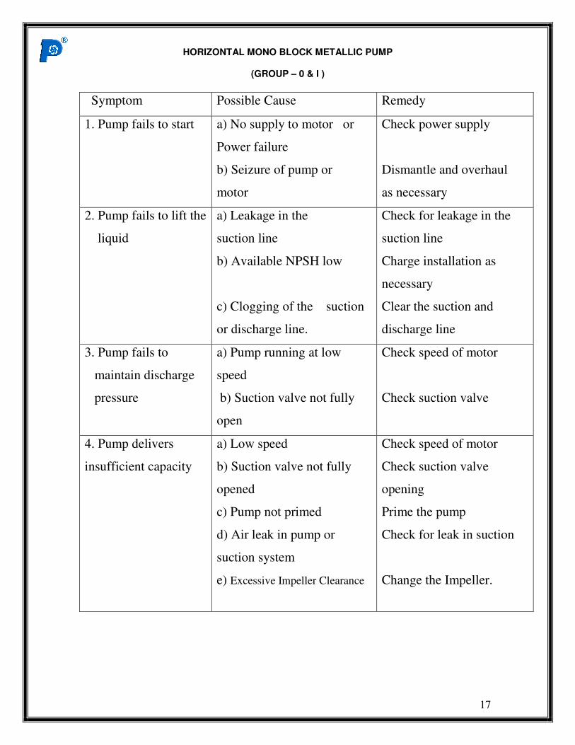
Symptom Possible Cause Remedy
1. Pump fails to start
a) No supply to motor or
Power failure
b) Seizure of pump or
motor
Check power supply
Dismantle and overhaul
as necessary
2. Pump fails to lift the
liquid
a) Leakage in the
suction line
b) Available NPSH low
c) Clogging of the suction
or discharge line.
Check for leakage in the
suction line
Charge installation as
necessary
Clear the suction and
discharge line
3. Pump fails to
maintain discharge
pressure
a) Pump running at low
speed
b) Suction valve not fully
open
Check speed of motor
Check suction valve
4. Pump delivers
insufficient capacity
a) Low speed
b) Suction valve not fully
opened
c) Pump not primed
d) Air leak in pump or
suction system
e) Excessive Impeller Clearance
Check speed of motor
Check suction valve
opening
Prime the pump
Check for leak in suction
Change the Impeller.
HORIZONTAL MONO BLOCK METALLIC PUMP
(GROUP – 0 & I )
18
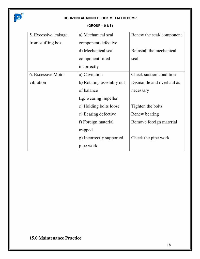
5. Excessive leakage
from stuffing box
a) Mechanical seal
component defective
d) Mechanical seal
component fitted
incorrectly
Renew the seal/ component
Reinstall the mechanical
seal
6. Excessive Motor
vibration
a) Cavitation
b) Rotating assembly out
of balance
Eg: wearing impeller
c) Holding bolts loose
e) Bearing defective
f) Foreign material
trapped
g) Incorrectly supported
pipe work
Check suction condition
Dismantle and overhaul as
necessary
Tighten the bolts
Renew bearing
Remove foreign material
Check the pipe work
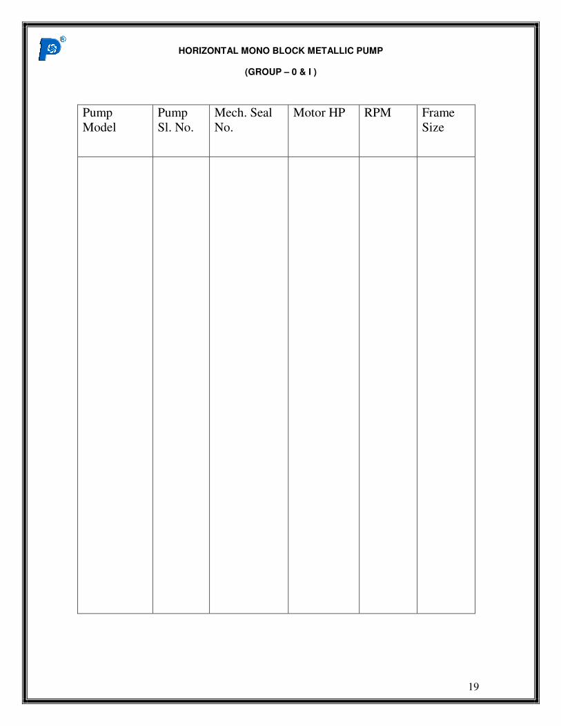
15.0 Maintenance Practice
HORIZONTAL MONO BLOCK METALLIC PUMP
(GROUP – 0 & I )
19
Pump
Model
Pump
Sl. No.
Mech. Seal
No.
Motor HP
RPM
Frame
Size
Recommended