Product Data
FMA4X, FMA4PAPARTMENT FAN COIL UNIT
1−1/2 TONS THROUGH 3 TONS
APARTMENT FAN COILSALL MODELS· 1−1/2, 2, 2−1/2, and 3 Tons· Upflow application only· Accessory field−installed electric heat kits available in 5,
7.5, or 10 kW· 208/230−1−60 supply voltage· Cabinet exterior is galvanized sheet metal· Cabinet air leakage rate below 1.4% when tested to
ASHRAE Standard 193· Insulated for conditioned space (not to be installed in
unconditioned spaces)· All Aluminum coilsFMA4P· For use with R−410A refrigerant utilizing standard pistonFMA4X· R−410A refrigerant, TXV standardPERFORMANCE· PSC motor on all FMA4P· ECM motor on all FMA4X· Motor suspended on rubber grommets for quieter
operation· Fresh air intake knockouts in cabinetEASY TO INSTALL AND SERVICE· Units fits between standard stud spacings· All service access is located in the front· Primary and secondary drain connections exit from the
bottom, access panel in bottom of cabinet· No return−air ductwork required in specific applications· Wall hanging brackets included with the unit
A180014
Use of the AHRI Certified TM Mark indic-ates a manufacturer’s participation in theprogram. For verification of certification forindividual products, go to www.ahridirect-ory.org .
Model TonsNominal
BTU
CFM (L/s) DimensionsH x W x D in. (mm)
Filter Sizein. (mm)
Ship Wt.lbs. (kg)Min Max
FMA4P1800AL 1−1/2 18,000 450 (212) 675 (319) 36−1/2 x 20−1/2 x 15(928 x 521 x 381) 16 x 20 (406 x 508)
101 (46)FMA4P2400AL 2 24,000 600 (283) 900 (425) 101 (46)FMA4P3000AL 2−1/2 30,000 750 (354) 1125 (531) 39−1/2 x 22 x 19
(1004 x 559 x 483) 20 x 20 (508 x 508)123 (56)
FMA4P3600AL 3 36,000 900 (425) 1350 (637) 123 (56)
FMA4X1800AL 1−1/2 18,000 450 (212) 675 (319) 36−1/2 x 20−1/2 x 15(928 x 521 x 381) 16 x 20 (406 x 508)
101 (46)FMA4X2400AL 2 24,000 600 (283) 900 (425) 101 (46)FMA4X3000AL 2−1/2 30,000 750 (354) 1125 (531) 39−1/2 x 22 x 19
(1004 x 559 x 483)20 x 20 (508 x 508)
123 (56)FMA4X3600AL 3 36,000 900 (425) 1350 (637) 123 (56)
2
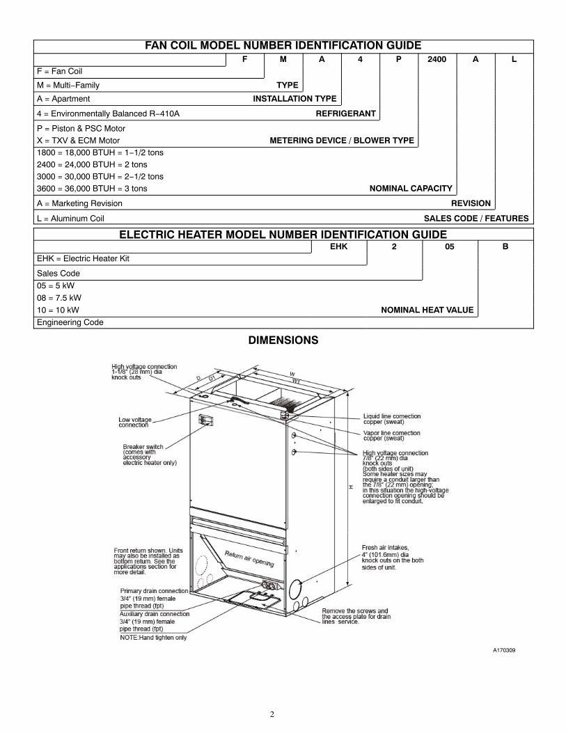
FAN COIL MODEL NUMBER IDENTIFICATION GUIDEF M A 4 P 2400 A L
F = Fan Coil
M = Multi−Family TYPE
A = Apartment INSTALLATION TYPE
4 = Environmentally Balanced R−410A REFRIGERANT
P = Piston & PSC MotorX = TXV & ECM Motor METERING DEVICE / BLOWER TYPE1800 = 18,000 BTUH = 1−1/2 tons2400 = 24,000 BTUH = 2 tons3000 = 30,000 BTUH = 2−1/2 tons3600 = 36,000 BTUH = 3 tons NOMINAL CAPACITY
A = Marketing Revision REVISION
L = Aluminum Coil SALES CODE / FEATURES
ELECTRIC HEATER MODEL NUMBER IDENTIFICATION GUIDEEHK 2 05 B
EHK = Electric Heater Kit
Sales Code
05 = 5 kW
08 = 7.5 kW
10 = 10 kW NOMINAL HEAT VALUEEngineering Code
DIMENSIONS
A170309

3
DIMENSIONSUnit Size kbtu 18 24 30 36
Power supply V-Ph-Hz 208/230V 1Ph 60Hz 208/230V 1Ph 60Hz 208/230V 1Ph 60Hz 208/230V 1Ph 60Hz
Indoor unit
Dimension(WxHxD)
mm 522x928x 381 522x928x 381 554x1003x482 554x1003x482
inch 20-1/2x36-1/2x15 20-1/2x36-1/2x15 22x39-1/2x19 22x39-1/2x19
Packing(WxHxD)
mm 580x1060x440 580x1060x440 615x1140x540 615x1140x540
inch 22-4/5x41-3/5x17-1/3 22-4/5x41-3/5x17-1/3 24-1/5x44-4/5x21-1/4 24-1/5x44-4/5x21-1/4
Net/GrossWeight
Kg39/46 (PSC)36/43 (ECM)
39/46 (PSC)36/43 (ECM)
46/56 (PSC)44/54 (ECM)
46/56 (PSC)44/54 (ECM)
lbs86/101 (PSC)79/95 (ECM)
86/101 (PSC)79/95 (ECM)
101/123 (PSC)97/119 (ECM)
101/123 (PSC)97/119 (ECM)
DuctConnection
Dimension(W1xD1)
mm 422x242 422x242 477x242 477x242
inch 17-2/5x9-1/2 17-2/5x9-1/2 18-4/5x9-1/2 18-4/5x9-1/2
Drain PanConnection
Primary/Auxiliary
inch 3/4 FPT / 3/4 FPT 3/4 FPT / 3/4 FPT 3/4 FPT / 3/4 FPT 3/4 FPT / 3/4 FPT
REQUIRED CLEARANCES − ALL MODELS inches (mm)
No HeatersAll Sides 0
From Supply Duct 0
With HeatersAll Sides 0
From Supply Duct 0
PHYSICAL DATAUnit Size
FMA4P 18 24 30 36
Nominal Cooling Capacity (BTUH) 18,000 24,000 30,000 36,000
COIL
R410-A Refrigerant metering Device Piston* .049 .057 .065 .070
Fins Per In. 17 17 17 17
Face Area Ft2 2.149 2.149 2.955 2.955
Coil Configuration Slope
BLOWER & MOTOR
Air Discharge Upflow
Blower Type Direct Drive
CFM (Nominal) 600 800 1000 1200
Motor Type PSC PSC PSC PSC
Motor HP 1/6 1/4 1/3 1/2
Rated RPM 1075 1075 1075 1075
Motor Speeds 3 3 3 3
FILTER
Field Installed - in (mm)16x20x1
(406x508x25)16x20x1
(406x508x25)20x20x1
(508x508x25)20x20x1
(508x508x25)
CONNECTIONS (Sweat)
Suction - in. (mm) 3/4 In. (19 mm)
Liquid - in. (mm) 3/8 In. (9.5 mm)
Condensate (FPT) - in. (mm) 3/4 In. (19 mm)
ELECTRICAL DATA
Voltage 208/230 208/230 208/230 208/230
Hertz 60 60 60 60
Circuit Amps 0.8 1.0 1.28 1.8
Minimum Circuit Ampacity 1 1.3 1.6 2.3
Maximum Circuit Protector 15 (A) 15 (A) 15 (A) 15 (A)
* The piston included with the fan coil is unique to this product and CANNOT be replaced with the piston shipped with outdoor unit. Refer to the AHRI ratings to check ifyour combination can use the piston shipped with the unit or requires an accessory TXV.

4
PERFORMANCE DATAPSC − AIRFLOW PERFORMANCE (STANDARD CFM)
MODELSBLOWERSPEEDS
EXTERNAL STATIC PRESSURE (IN WC.)0 0.1 0.2 0.3 0.4 0.5 0.6 0.7 0.8
FMA4P1800ALHigh 813 775 731 692 653 609 560 501 424Med 695 656 620 581 540 498 440 380 −Low 603 562 525 485 443 393 − − −
FMA4P2400ALHigh 947 895 847 799 753 704 655 592 530Med 845 801 759 716 675 626 573 510 −Low 676 640 602 563 523 499 − − −
FMA4P3000ALHigh 1367 1312 1252 1192 1131 1063 990 908 821Med 1211 1165 1114 1065 1016 960 899 833 748Low 992 952 912 873 828 782 728 656 627
FMA4P3600ALHigh 1397 1345 1290 1263 1196 1116 1051 980 907Med 1298 1252 1198 1147 1094 1037 976 910 842Low 1149 1105 1056 1008 960 909 856 791 726
- Shaded boxes represent airflow outside the required 300450 CFM/ton.
NOTES:
1. Airflow data includes electric heat and filter.2. Airflow data is with no return grill. When using a return grill on 18 & 24 sizes, decrease numbers above by approx. 10 CFM. For 30 & 36 sizes, decrease numbers above
by approx. 50 CFM
PHYSICAL DATAUnit Size
FMA4X 18 24 30 36
Nominal Cooling Capacity (BTUH) 18,000 24,000 30,000 36,000
COIL
Fins Per In. 17 17 17 17
Face Area Ft2 2.149 2.149 2.955 2.955
Coil Configuration Slope
BLOWER & MOTOR
Air Discharge Upflow
Blower Type Direct Drive
CFM (Nominal) 600 800 1000 1200
Motor Type ECM ECM ECM ECM
Motor HP 1/3 1/3 1/2 1/2
Rated RPM 1050 1050 1050 1050
Motor Speeds 5 5 5 5
FILTER
Field Installed - in (mm)16x20x1
(406x508x25)16x20x1
(406x508x25)20x20x1
(508x508x25)20x20x1
(508x508x25)
CONNECTIONS (Sweat)
Suction - in. (mm) 3/4 In. (19 mm)
Liquid - in. (mm) 3/8 In. (9.5 mm)
Condensate (FPT) - in. (mm) 3/4 In. (19 mm)
ELECTRICAL DATA
Voltage 208/230 208/230 208/230 208/230
Hertz 60 60 60 60
Circuit Amps 1.9 1.9 2.7 2.7
Minimum Circuit Ampacity 2.4 2.4 3.4 3.4
Maximum Circuit Protector 15 15 15 15

5
PERFORMANCE DATA (cont.)ECM − AIRFLOW PERFORMANCE (STANDARD CFM)
MODEL SIZE BLOWERSPEEDS
EXTERNAL STATIC PRESSURE (IN WC.)0 0.1 0.2 0.3 0.4 0.5 0.6 0.7 0.8
FMA4X1800AL
Tap(5) 913 881 848 818 792 763 731 691 650
Tap(4) 825 787 753 717 682 650 617 580 540
Tap(3) 737 700 663 630 589 550 511 474 436
Tap(2)-Factory 675 632 596 555 521 480 440 399 366
Tap(1) 590 548 499 455 430 368 338 309 263
FMA4X2400AL
Tap(5) 913 881 848 818 792 763 731 691 650
Tap(4)-Factory 825 787 753 717 682 650 617 580 540
Tap(3) 737 700 663 630 589 550 511 474 436
Tap(2) 675 632 596 555 521 480 440 399 366
Tap(1) 590 548 499 455 430 368 338 309 263
FMA4X3000AL
Tap(5) 1362 1325 1266 1238 1197 1159 1119 1080 1040
Tap(4) 1282 1242 1176 1151 1111 1071 1028 975 936
Tap(3) 1267 1225 1143 1120 1078 1036 993 942 897
Tap(2)-Factory 1157 1111 1052 1016 971 929 884 842 802
Tap(1) 1077 1028 965 932 886 850 804 768 732
FMA4X3600AL
Tap(5) 1362 1325 1266 1238 1197 1159 1119 1080 1040
Tap(4)-Factory 1282 1242 1176 1151 1111 1071 1028 975 936
Tap(3) 1267 1225 1143 1120 1078 1036 993 942 897
Tap(2) 1157 1111 1052 1016 971 929 884 842 802
Tap(1) 1077 1028 965 932 886 850 804 768 732
- Shaded boxes represent airflow outside the required 300450 CFM/ton.
NOTES:
1. Airflow based upon dry coil at 230V with no electric heat and factory-approved filter. For FMA4X airflow at 208V is approximately the same as 230V because themulti-tap ECM motor is a constant torque motor. The torque doesn't drop off at the speeds in which the motor operates.
2. Airflow is equivalent for front or bottom return configurations.
CFMSize Min Max18 450 67524 600 90030 750 112536 900 1350
SENSIBLE CAPACITY (SHC) CORRECTION FACTOR
BYPASS FACTOR
ENTERING AIR DRY-BULB TEMPERATURE (�F)
79 78 77 76 75 Under 75
81 82 83 84 85 Over 85
ENTERING AIR DRY-BULB TEMPERATURE (�C)
26 25 25 24 24 Under 75
27 28 28 29 29 Over 85
Correction Factor
0.10 .098 1.96 2.94 3.92 4.91 Useformulashownbelow
0.20 0.87 1.74 2.62 3.49 4.36
0.30 0.76 1.53 2.29 3.05 3.82
Interpolation is permissible.
Correction Factor = 1.09 x (1 - BF) x (db - 80)
NOTES:1. Contact manufacturer for cooling capacities at conditions other
than shown in table.2. Formulas:
Leaving db = entering db −sensible heat cap. 1.09 x CFMLeaving wb = wb corresponding to enthalpy of air leaving coil(hlwb)hlwb = hewb −total capacity (Btuh) 4.5 x CFMwhere hewb = enthalpy of air entering coil. Direct interpolation ispermissible. Do not extrapolate.
3. SHC is based on 80�F (27�C) db temperature of air entering coil.Below 80�F (27�C) db, subtract (Correction Factor x CFM) fromSHC. Above 80�F (27�C) db, add (Correction Factor x CFM) toSHC.
4. Bypass Factor = 0 indicates no psychometric solution. Use bypassfactor of next lower EWB for approximation.

6
PERFORMANCE DATA (cont.)
GROSS COOLING CAPACITIES (MBH)
INDOOR COIL AIRSATURATED TEMPERATURE LEAVING EVAPORATOR (deg F)
35 40 45 50 55CFM EWB TC SHC BF TC SHC BF TC SHC BF TC SHC BF TC SHC BF
FMA4(X,P)1800AL
52572 29.75 13.91 0.00 27.17 12.76 0.01 24.23 11.51 0.02 20.89 10.17 0.02 17.13 8.77 0.0267 24.71 14.48 0.03 22.05 13.24 0.03 19.02 11.91 0.03 15.59 10.50 0.03 11.73 9.03 0.0362 20.11 14.95 0.03 17.35 13.63 0.03 14.34 12.28 0.03 11.68 11.68 0.06 9.91 9.91 0.20
60072 32.47 15.15 0.00 29.68 13.92 0.02 26.50 12.59 0.02 22.86 11.15 0.03 18.75 9.64 0.0367 27.04 15.91 0.03 24.15 14.58 0.03 20.85 13.15 0.03 17.10 11.62 0.03 12.87 10.02 0.0362 22.04 16.54 0.03 19.03 15.12 0.03 15.77 13.66 0.03 12.99 12.99 0.08 11.02 11.02 0.22
67572 34.94 16.29 0.01 31.98 15.00 0.02 28.57 13.60 0.03 24.67 12.08 0.03 20.26 10.47 0.0367 29.15 17.24 0.04 26.08 15.85 0.04 22.53 14.33 0.04 18.50 12.70 0.04 13.93 10.98 0.0462 23.81 18.05 0.04 20.61 16.55 0.04 17.10 14.99 0.04 14.24 14.24 0.10 12.08 12.08 0.23
INDOOR COIL AIRSATURATED TEMPERATURE LEAVING EVAPORATOR (deg F)
35 40 45 50 55CFM EWB TC SHC BF TC SHC BF TC SHC BF TC SHC BF TC SHC BF
FMA4(X,P)2400AL
70072 37.53 18.55 0.01 34.36 17.10 0.03 30.70 15.51 0.03 26.52 13.79 0.04 21.79 11.96 0.0467 31.33 19.68 0.04 28.04 18.11 0.04 24.24 16.39 0.04 19.90 14.54 0.04 15.00 12.59 0.0462 25.60 20.65 0.04 22.17 18.96 0.04 18.42 17.19 0.04 15.39 15.39 0.10 13.05 13.05 0.24
80072 40.55 20.05 0.03 37.16 18.53 0.03 33.24 16.86 0.04 28.73 15.04 0.04 23.67 13.10 0.0467 33.93 21.49 0.05 30.40 19.83 0.05 26.32 18.01 0.05 21.65 16.05 0.05 16.35 13.94 0.0562 27.80 22.74 0.05 24.14 20.96 0.05 20.14 19.08 0.05 17.05 17.05 0.12 14.46 14.46 0.26
90072 43.24 21.41 0.04 39.65 19.84 0.04 35.50 18.10 0.05 30.72 16.19 0.05 25.36 14.17 0.0567 36.24 23.16 0.05 32.51 21.44 0.05 28.19 19.54 0.05 23.22 17.48 0.05 17.59 15.25 0.0562 29.76 24.71 0.05 25.92 22.86 0.05 21.74 20.87 0.06 18.61 18.61 0.15 15.79 15.79 0.27
INDOOR COIL AIRSATURATED TEMPERATURE LEAVING EVAPORATOR (deg F)
35 40 45 50 55CFM EWB TC SHC BF TC SHC BF TC SHC BF TC SHC BF TC SHC BF
FMA4(X,P)3000AL
87572 47.47 21.63 0.00 43.42 19.90 0.02 38.78 18.01 0.03 33.46 15.96 0.03 27.43 13.79 0.0367 39.55 22.86 0.03 35.35 20.99 0.03 30.52 18.95 0.04 25.01 16.76 0.04 18.78 14.44 0.0462 32.25 23.91 0.04 27.87 21.89 0.04 23.08 19.80 0.04 19.10 19.10 0.09 16.16 16.16 0.23
100072 51.44 23.44 0.02 47.10 21.62 0.03 42.11 19.63 0.03 36.37 17.46 0.04 29.88 15.15 0.0467 42.96 25.02 0.04 38.45 23.04 0.04 33.25 20.88 0.04 27.29 18.53 0.04 20.53 16.04 0.0462 35.12 26.39 0.04 30.43 24.25 0.04 25.29 22.01 0.04 21.21 21.21 0.11 17.95 17.95 0.25
112572 54.98 25.09 0.03 50.40 23.21 0.04 45.09 21.12 0.04 38.98 18.84 0.04 32.11 16.42 0.0467 46.01 27.02 0.05 41.24 24.96 0.05 35.71 22.69 0.05 29.36 20.23 0.05 22.15 17.58 0.0562 37.70 28.72 0.05 32.76 26.51 0.05 27.36 24.14 0.05 23.22 23.22 0.13 19.66 19.66 0.27
INDOOR COIL AIRSATURATED TEMPERATURE LEAVING EVAPORATOR (deg F)
35 40 45 50 55CFM EWB TC SHC BF TC SHC BF TC SHC BF TC SHC BF TC SHC BF
FMA4(X,P)3600AL
105072 54.59 26.69 0.02 50.01 24.65 0.03 44.72 22.40 0.04 38.64 19.95 0.04 31.78 17.34 0.0467 45.63 28.59 0.04 40.86 26.37 0.04 35.36 23.92 0.04 29.04 21.27 0.04 21.87 18.44 0.0562 37.33 30.25 0.05 32.38 27.85 0.04 26.97 25.31 0.05 22.73 22.73 0.12 19.24 19.24 0.26
120072 58.74 28.79 0.03 53.86 26.67 0.04 48.22 24.31 0.05 41.71 21.72 0.05 34.40 18.98 0.0567 49.21 31.17 0.05 44.13 28.84 0.05 38.25 26.27 0.05 31.48 23.46 0.05 23.80 20.44 0.0562 40.37 33.27 0.05 35.14 30.77 0.05 29.44 28.08 0.06 25.15 25.15 0.14 21.30 21.30 0.27
135072 62.40 30.69 0.04 57.27 28.51 0.05 51.32 26.07 0.05 44.43 23.37 0.06 36.70 20.51 0.0667 52.38 33.56 0.06 47.03 31.15 0.06 40.83 28.47 0.06 33.69 25.54 0.06 25.56 22.36 0.0662 43.07 36.12 0.06 37.62 33.54 0.06 31.73 30.70 0.07 27.42 27.42 0.17 23.25 23.25 0.29

7
PERFORMANCE DATA (cont.)ESTIMATED SOUND POWER LEVEL (dBA)
FMA ESTIMATED SOUND PRESSURE LEVEL
Unit Size kbtu 18 24 30 36
Indoor sound pressure leveldBAHigh
50 54 54 54
UNIT SIZE
CONDITIONS OCTAVE BAND CENTER FREQUENCY
CFM Ext Static Pressure 63 125 250 500 1000 2000 4000
18 600 0.25 46 52.1 48.9 51.8 52.5 51.7 49.7
24 800 0.25 54.1 57.1 58.6 59 61.5 59.8 57
30 1000 0.25 51.6 52.6 52.6 53.3 56.1 52.8 59.7
36 1200 0.25 52.6 52.3 54.6 54.3 57.2 53.8 50.4
* Estimated sound power levels have been derived using the method described in the 1987 ASHRAE HVAC Systems & Applications Handbook, Chapter 52, p. 52.7.
ELECTRICAL DATA FOR FAN COIL WITH ELECTRIC HEAT COMBINED ELECTRICAL DATA
Nominal Fan Coil CapacityNominal Heat Capacity @
240VMinimum Circuit Ampacity
(MCA)MAX.Fuse or Breaker
Heat Kit (HACR) Ampacity
MBTU KW 208 240 208 240
18, PSC
5 23.6 27.1 30 30
7.5 34.9 40.1 45 45
10 46.2 53.1 60 60
24, PSC
5 23.9 27.3 30 30
7.5 35.2 40.4 45 45
10 46.4 53.4 60 60
30, PSC
5 24.2 27.7 30 30
7.5 35.5 40.7 45 45
10 46.8 53.7 60 60
36, PSC
5 24.9 28.3 30 30
7.5 36.2 41.4 45 45
10 47.4 54.4 60 60
18, ECM
5 25.0 28.5 30 30
7.5 36.3 41.5 45 45
10 47.6 54.5 60 60
24, ECM
5 25.0 28.5 30 30
7.5 36.3 41.5 45 45
10 47.6 54.5 60 60
30, ECM
5 26.0 29.5 30 30
7.5 37.3 42.5 45 45
10 48.6 55.5 60 60
36, ECM
5 26.0 29.5 30 30
7.5 37.3 42.5 45 45
10 48.6 55.5 60 60
8
PERFORMANCE DATA (cont.)
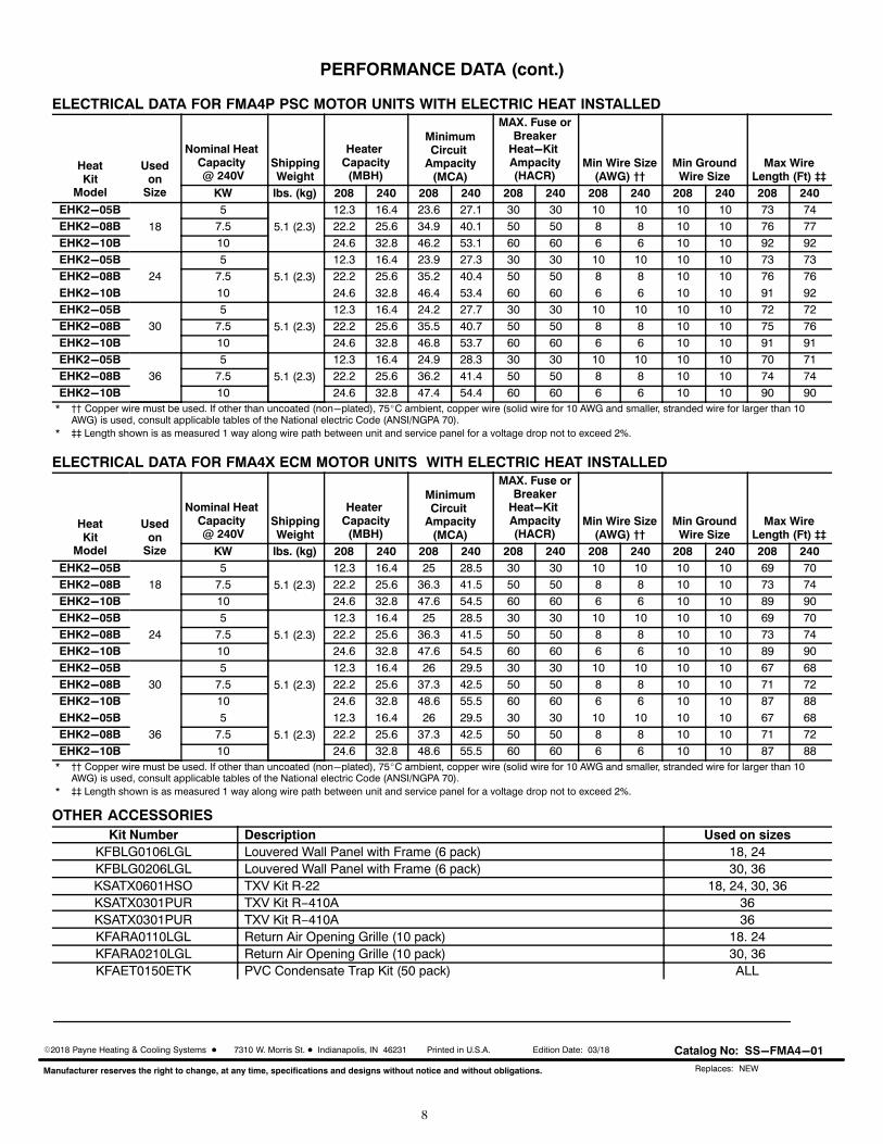
ELECTRICAL DATA FOR FMA4P PSC MOTOR UNITS WITH ELECTRIC HEAT INSTALLED
HeatKit
Model
Usedon
Size
Nominal Heat Capacity @ 240V
ShippingWeight
Heater Capacity(MBH)
MinimumCircuit
Ampacity(MCA)
MAX. Fuse orBreaker
Heat-Kit Ampacity(HACR)
Min Wire Size(AWG) ††
Min GroundWire Size
Max WireLength (Ft) ‡‡
KW lbs. (kg) 208 240 208 240 208 240 208 240 208 240 208 240
EHK2-05B
18
5
5.1 (2.3)
12.3 16.4 23.6 27.1 30 30 10 10 10 10 73 74
EHK2-08B 7.5 22.2 25.6 34.9 40.1 50 50 8 8 10 10 76 77
EHK2-10B 10 24.6 32.8 46.2 53.1 60 60 6 6 10 10 92 92
EHK2-05B
24
5
5.1 (2.3)
12.3 16.4 23.9 27.3 30 30 10 10 10 10 73 73
EHK2-08B 7.5 22.2 25.6 35.2 40.4 50 50 8 8 10 10 76 76
EHK2-10B 10 24.6 32.8 46.4 53.4 60 60 6 6 10 10 91 92
EHK2-05B
30
5
5.1 (2.3)
12.3 16.4 24.2 27.7 30 30 10 10 10 10 72 72
EHK2-08B 7.5 22.2 25.6 35.5 40.7 50 50 8 8 10 10 75 76
EHK2-10B 10 24.6 32.8 46.8 53.7 60 60 6 6 10 10 91 91
EHK2-05B
36
5
5.1 (2.3)
12.3 16.4 24.9 28.3 30 30 10 10 10 10 70 71
EHK2-08B 7.5 22.2 25.6 36.2 41.4 50 50 8 8 10 10 74 74
EHK2-10B 10 24.6 32.8 47.4 54.4 60 60 6 6 10 10 90 90
* †† Copper wire must be used. If other than uncoated (non-plated), 75�C ambient, copper wire (solid wire for 10 AWG and smaller, stranded wire for larger than 10AWG) is used, consult applicable tables of the National electric Code (ANSI/NGPA 70).
* ‡‡ Length shown is as measured 1 way along wire path between unit and service panel for a voltage drop not to exceed 2%.
ELECTRICAL DATA FOR FMA4X ECM MOTOR UNITS WITH ELECTRIC HEAT INSTALLED
HeatKit
Model
Usedon
Size
Nominal Heat Capacity @ 240V
ShippingWeight
Heater Capacity(MBH)
MinimumCircuit
Ampacity(MCA)
MAX. Fuse orBreaker
Heat-Kit Ampacity(HACR)
Min Wire Size(AWG) ††
Min GroundWire Size
Max WireLength (Ft) ‡‡
KW lbs. (kg) 208 240 208 240 208 240 208 240 208 240 208 240
EHK2-05B
18
5
5.1 (2.3)
12.3 16.4 25 28.5 30 30 10 10 10 10 69 70
EHK2-08B 7.5 22.2 25.6 36.3 41.5 50 50 8 8 10 10 73 74
EHK2-10B 10 24.6 32.8 47.6 54.5 60 60 6 6 10 10 89 90
EHK2-05B
24
5
5.1 (2.3)
12.3 16.4 25 28.5 30 30 10 10 10 10 69 70
EHK2-08B 7.5 22.2 25.6 36.3 41.5 50 50 8 8 10 10 73 74
EHK2-10B 10 24.6 32.8 47.6 54.5 60 60 6 6 10 10 89 90
EHK2-05B
30
5
5.1 (2.3)
12.3 16.4 26 29.5 30 30 10 10 10 10 67 68
EHK2-08B 7.5 22.2 25.6 37.3 42.5 50 50 8 8 10 10 71 72
EHK2-10B 10 24.6 32.8 48.6 55.5 60 60 6 6 10 10 87 88
EHK2-05B
36
5
5.1 (2.3)
12.3 16.4 26 29.5 30 30 10 10 10 10 67 68
EHK2-08B 7.5 22.2 25.6 37.3 42.5 50 50 8 8 10 10 71 72
EHK2-10B 10 24.6 32.8 48.6 55.5 60 60 6 6 10 10 87 88
* †† Copper wire must be used. If other than uncoated (non-plated), 75�C ambient, copper wire (solid wire for 10 AWG and smaller, stranded wire for larger than 10AWG) is used, consult applicable tables of the National electric Code (ANSI/NGPA 70).
* ‡‡ Length shown is as measured 1 way along wire path between unit and service panel for a voltage drop not to exceed 2%.
OTHER ACCESSORIESKit Number Description Used on sizes
KFBLG0106LGL Louvered Wall Panel with Frame (6 pack) 18, 24KFBLG0206LGL Louvered Wall Panel with Frame (6 pack) 30, 36KSATX0601HSO TXV Kit R-22 18, 24, 30, 36KSATX0301PUR TXV Kit R−410A 36KSATX0301PUR TXV Kit R−410A 36KFARA0110LGL Return Air Opening Grille (10 pack) 18. 24KFARA0210LGL Return Air Opening Grille (10 pack) 30, 36KFAET0150ETK PVC Condensate Trap Kit (50 pack) ALL
�2018 Payne Heating & Cooling Systems � 7310 W. Morris St. � Indianapolis, IN 46231 Printed in U.S.A. Edition Date: 03/18
Manufacturer reserves the right to change, at any time, specifications and designs without notice and without obligations.
Catalog No: SS-FMA4-01
Replaces: NEW
Recommended