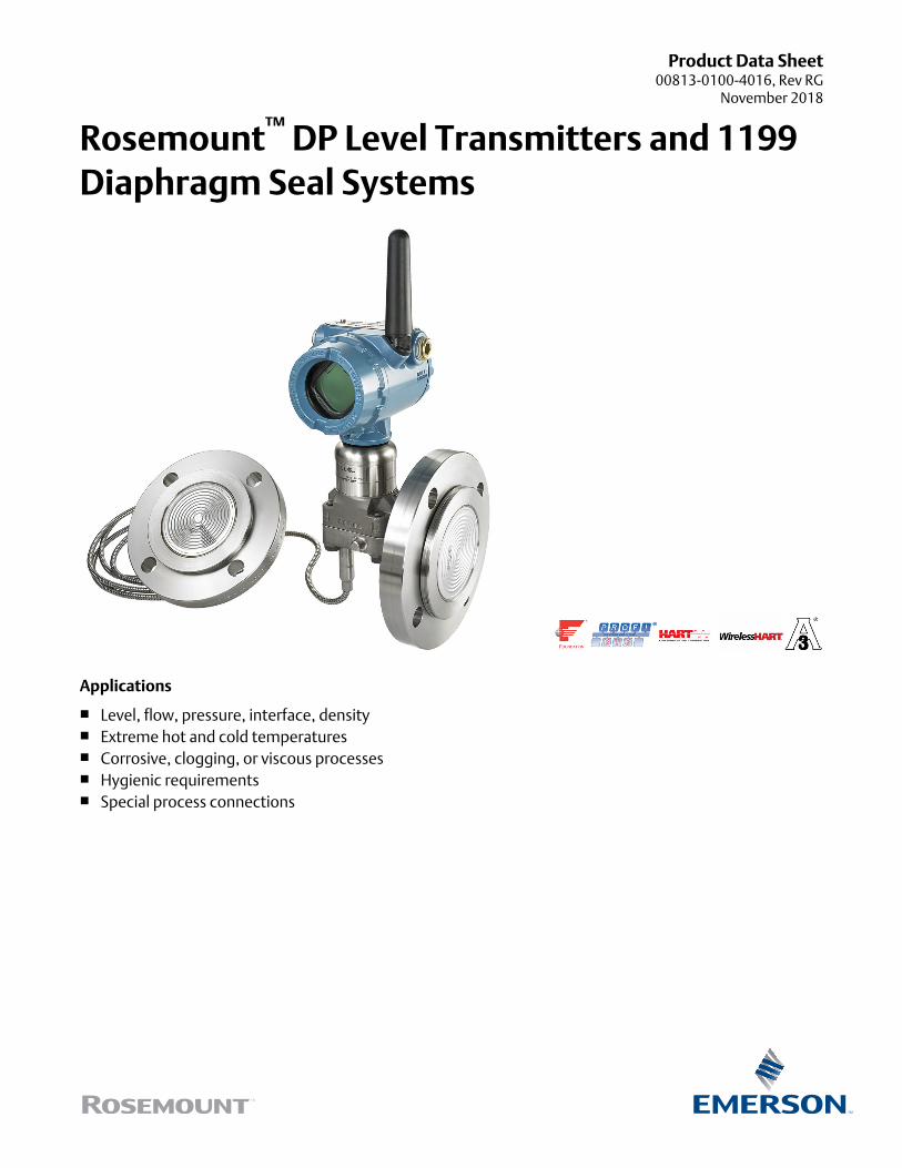
Product Data Sheet00813-0100-4016, Rev RG
November 2018
Rosemount™ DP Level Transmitters and 1199Diaphragm Seal Systems
Applications
■ Level, flow, pressure, interface, density■ Extreme hot and cold temperatures■ Corrosive, clogging, or viscous processes■ Hygienic requirements■ Special process connections
Proven, reliable, and innovative DP Level technologiesTo meet your application requirements, Rosemount™ DP Level technologies deliver an unsurpassed product offering that is easy tospecify, order, and install. The offering includes a wide variety of process connections, direct mount or capillary connections, andmaterials of construction to address almost any application. If you don’t see what you need listed here, ask us. We can create acustom engineered solution to meet your needs.
Rosemount Level TransmittersLevel transmitters combine world-class Rosemount pressure instrumentation with direct-mount seals, all in a single integratedmodel number.
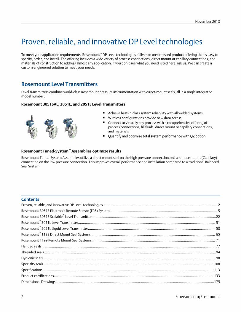
Rosemount 3051SAL, 3051L, and 2051L Level Transmitters
■ Achieve best-in-class system reliability with all welded systems■ Wireless configurations provide new data access■ Connect to virtually any process with a comprehensive offering of
process connections, fill fluids, direct mount or capillary connections,and materials
■ Quantify and optimize total system performance with QZ option
Rosemount Tuned-System™ Assemblies optimize results
Rosemount Tuned-System Assemblies utilize a direct mount seal on the high pressure connection and a remote mount (Capillary)connection on the low pressure connection. This improves overall performance and installation compared to a traditional BalancedSeal System.
ContentsProven, reliable, and innovative DP Level technologies ..................................................................................................................... 2
Rosemount 3051S Electronic Remote Sensor (ERS) System............................................................................................................... 5
Rosemount 3051S Scalable™
Level Transmitter................................................................................................................................22
Rosemount™
3051L Level Transmitter............................................................................................................................................. 51
Rosemount™
2051L Liquid Level Transmitter................................................................................................................................... 58
Rosemount™
1199 Direct Mount Seal Systems................................................................................................................................ 65
Rosemount 1199 Remote Mount Seal Systems............................................................................................................................... 71
Flanged seals................................................................................................................................................................................... 77
Threaded seals.................................................................................................................................................................................94
Hygienic seals..................................................................................................................................................................................98
Specialty seals............................................................................................................................................................................... 108
Specifications................................................................................................................................................................................ 113
Product certifications.................................................................................................................................................................... 133
Dimensional Drawings...................................................................................................................................................................175
November 2018
2 Emerson.com/Rosemount
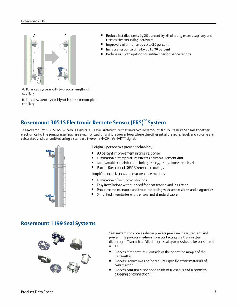
A. Balanced system with two equal lengths ofcapillary
B. Tuned-system assembly with direct mount pluscapillary
■ Reduce installed costs by 20 percent by eliminating excess capillary andtransmitter mounting hardware
■ Improve performance by up to 30 percent■ Increase response time by up to 80 percent■ Reduce risk with up-front quantified performance reports
Rosemount 3051S Electronic Remote Sensor (ERS)™ SystemThe Rosemount 3051S ERS System is a digital DP Level architecture that links two Rosemount 3051S Pressure Sensors togetherelectronically. The pressure sensors are synchronized on a single power loop where the differential pressure, level, and volume arecalculated and transmitted using a standard two-wire 4–20 mA HART® signal.
A digital upgrade to a proven technology
■ 90 percent improvement in time response■ Elimination of temperature effects and measurement drift■ Multivariable capabilities including DP, PLO, PHI, volume, and level■ Proven Rosemount 3051S Sensor technology
Simplified installations and maintenance routines
■ Elimination of wet legs or dry legs■ Easy installations without need for heat tracing and insulation■ Proactive maintenance and troubleshooting with sensor alerts and diagnostics■ Simplified inventories with sensors and standard cable
Rosemount 1199 Seal Systems
Seal systems provide a reliable process pressure measurement andprevent the process medium from contacting the transmitterdiaphragm. Transmitter/diaphragm seal systems should be consideredwhen:
■ Process temperature is outside of the operating ranges of thetransmitter.
■ Process is corrosive and/or requires specific exotic materials ofconstruction.
■ Process contains suspended solids or is viscous and is prone toplugging of connections.
November 2018
Product Data Sheet 3
■ Application requires the use of flush-mount hygienic connectionsthat facilitates CIP/SIP service.
■ There is a requirement for easier cleaning of the process from theconnections to avoid contamination between batches.
Application flexibility■ Flanged, threaded, and hygienic process connections■ Meets industry standards such as EN 1092-1, ANSI/ASME B16.5, JIS B2238, ANSI/ASME B1.20.1, EN 10226-1, GOST 33259-15,
ISO 228-1■ Variety of fill fluids applications including cold temperature, hot temperature, and hygienic and food grade■ Three different capillary diameters allow for optimization of accuracy and time response
Reliable system construction■ Welded design with no threaded connections■ 100 percent helium leak tested■ Advanced manufacturing techniques ensure air-free, leak-tight system that is stable over time■ Reliable operation in full vacuum applications
Robust seal design■ Backup convolutions on the diaphragm protect seal integrity■ Recessed diaphragms reduce potential for handling damage
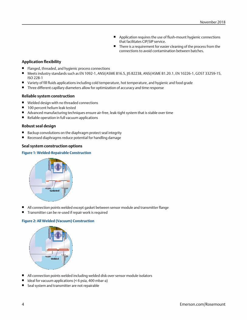
Seal system construction options
Figure 1: Welded-Repairable Construction
■ All connection points welded except gasket between sensor module and transmitter flange■ Transmitter can be re-used if repair work is required
Figure 2: All Welded (Vacuum) Construction
■ All connection points welded including welded disk over sensor module isolators■ Ideal for vacuum applications (< 6 psia, 400 mbar-a)■ Seal system and transmitter are not repairable
November 2018
4 Emerson.com/Rosemount
Rosemount 3051S Electronic Remote Sensor (ERS) System
The Rosemount 3051S ERS System is a flexible, 2-wire 4-20 mA HART architecture that calculatesdifferential pressure (DP) electronically using two pressure sensors that are linked together witha non-proprietary electrical wire.
Ideal applications for the Rosemount 3051S ERS System include tall vessels and distillationcolumns that have traditionally required long lengths of capillary or impulse piping. When usedin these types of applications, the Rosemount 3051S ERS System can deliver:
■ More accurate and repeatable DP measurements■ Faster time response■ Simplified installations■ Reduced maintenance
How to order
Procedure
1. Choose two Rosemount 3051S ERS Transmitter models. These may be any combination of Rosemount 3051SAM andRosemount 3051SAL models.
Example
Rosemount 3051SAM
Coplanar In-line
Example
Rosemount 3051SAL
Coplanar In-line
2. Decide which model will be the ERS Primary (4–20 mA loop termination and optional LCD display) and which will be the ERSSecondary. This will be specified by the “Configuration Type” code in each model number.
November 2018
Product Data Sheet 5
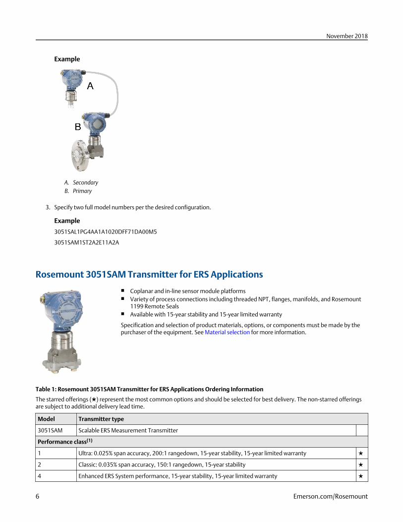
Example
A. SecondaryB. Primary
3. Specify two full model numbers per the desired configuration.
Example
3051SAL1PG4AA1A1020DFF71DA00M5
3051SAM1ST2A2E11A2A
Rosemount 3051SAM Transmitter for ERS Applications
■ Coplanar and in-line sensor module platforms■ Variety of process connections including threaded NPT, flanges, manifolds, and Rosemount
1199 Remote Seals■ Available with 15-year stability and 15-year limited warranty
Specification and selection of product materials, options, or components must be made by thepurchaser of the equipment. See Material selection for more information.
Table 1: Rosemount 3051SAM Transmitter for ERS Applications Ordering Information
The starred offerings (★) represent the most common options and should be selected for best delivery. The non-starred offeringsare subject to additional delivery lead time.
Model Transmitter type
3051SAM Scalable ERS Measurement Transmitter
Performance class(1)
1 Ultra: 0.025% span accuracy, 200:1 rangedown, 15-year stability, 15-year limited warranty ★
2 Classic: 0.035% span accuracy, 150:1 rangedown, 15-year stability ★
4 Enhanced ERS System performance, 15-year stability, 15-year limited warranty ★
November 2018
6 Emerson.com/Rosemount
Table 1: Rosemount 3051SAM Transmitter for ERS Applications Ordering Information (continued)
Configuration type
P ERS - primary ★
S ERS - secondary ★
Pressure module type Pressure sensor type
G Coplanar Gage ★
T In-Line Gage ★
E In-Line Absolute ★
A Coplanar Absolute
Pressure range(2)
Coplanar gage In-line gage In-line absolute Coplanar absolute
1A N/A –14.7 to 30 psig
(–1,01 to 2,06 bar)
0 to 30 psia
(0 to 2,06 bar)
0 to 30 psia
(0 to 2,06 bar)
★
2A –250 to 250 inH2O
(–621,60 to 621,60mbar)
–14.7 to 150 psig
(–1,01 to 10,34 bar)
0 to 150 psia
(0 to 10,34 bar)
0 to 150 psia
(0 to 10,34 bar)
★
3A –393 to 1000 inH2O
(–0,97 to 2,48 bar)
–14.7 to 800 psig
(–1,01 to 55,15 bar)
0 to 800 psia
(0 to 55,15 bar)
0 to 800 psia
(0 to 55,15 bar)
★
4A –14.2 to 300 psig
(–0,97 to 20,68 bar)
–14.7 to 4000 psig
(–1,01 to 275,79 bar)
0 to 4000 psia (0 to 275,79bar)
0 to 4000 psia
(0 to 275,79 bar)
★
5A –14.2 to 2000 psig
(–0,97 to 137,89bar)
–14.7 to 10000 psig
(–1,01 to 689,47 bar)
0 to 10000 psia
(0 to 689,47 bar)
N/A ★
Isolating diaphragm
2(3)(4) 316L stainless steel (SST) ★
3(3) Alloy C-276 ★
4(3)(4) Alloy 400
5(4)(5) Tantalum
6(3)(4) Gold-plated Alloy 400 (includes graphite-filled PTFE O-Ring)
7(3)(4) Gold-plated 316L SST
Process connection
Coplanar module type In-line module type
A11(6) Assemble to Rosemount 305 Manifold Assemble to Rosemount 306 Manifold ★
A12(6) Assemble to Rosemount 304 or AMF Manifold withSST traditional flange
Assemble AMF Manifold to ½-14 NPT female processconnection
★
A15(6) Assemble to Rosemount 304 or AMF manifold to SSTtraditional flange with alloy C-276 drain vents
N/A ★
A22(6) Assemble to Rosemount 304 or AMF manifold to SSTcoplanar flange
N/A ★
November 2018
Product Data Sheet 7
Table 1: Rosemount 3051SAM Transmitter for ERS Applications Ordering Information (continued)
B11(6)(7) Assemble to one Rosemount 1199 RemoteDiaphragm Seal with SST transmitter flange
Assemble to one Rosemount 1199 RemoteDiaphragm
★
E11 Coplanar flange (CS), ¼–18 NPT, 316 SST drain vents ½ –14 NPT female ★
E12 Coplanar flange (SST), ¼–18 NPT, 316 SST drainvents
N/A ★
E13(3) Coplanar flange (Cast C-276), ¼–18 NPT, Alloy C-276drain vents
N/A ★
E14 Coplanar flange (Cast Alloy 400), ¼–18 NPT, Alloy400/K-500 drain vents
N/A ★
E15(3) Coplanar flange (SST), ¼–18 NPT, Alloy C-276 drainvents
N/A ★
E16(3) Coplanar flange (CS), ¼–18 NPT, Alloy C-276 drainvents
N/A ★
E21 Coplanar flange (CS), RC ¼, 316 SST drain vents N/A ★
E22 Coplanar flange (SST), RC ¼, 316 SST drain vents N/A ★
E23(3) Coplanar flange (Cast C-276), RC ¼, Alloy C-276 drainvents
N/A ★
E24 Coplanar flange (Cast Alloy 400), RC ¼, alloy 400/K-500 drain vents
N/A ★
E25(3) Coplanar flange (SST), RC ¼, Alloy C-276 drain vents N/A ★
E26(3) Coplanar flange (CS), RC ¼, Alloy C-276 drain vents N/A ★
F12 Traditional flange (SST), ¼–18 NPT, 316 SST drainvents
N/A ★
F13(3) Traditional flange (Cast C-276), ¼–18 NPT, AlloyC-276 drain vents
N/A ★
F14 Traditional flange (Cast Alloy 400), ¼–18 NPT, Alloy400/K-500 drain vents
N/A ★
F15(3) Traditional flange (SST), ¼–18 NPT, Alloy C-276 drainvents
N/A ★
F22 Traditional flange (SST), RC ¼, 316 SST drain vents N/A ★
F23(3) Traditional flange (Cast C-276), RC¼, Alloy C-276drain vents
N/A ★
F24 Traditional flange (Cast Alloy 400), RC¼, Alloy 400/K500 drain vents
N/A ★
F25(3) Traditional flange (SST), RC ¼, Alloy C-276 drainvents
N/A ★
F52 DIN-compliant traditional flange (SST), ¼–18 NPT,316 drain vents, 7 to 16-in. bolting
N/A ★
G11 Vertical mount level flange (SST), 2-in. ANSI Class150, 316 SST drain vents
G½ A DIN 16288 male (range 1–4 only) ★
G12 Vertical mount level flange (SST), 2-in. ANSI Class300, 316 SST drain vents
N/A ★
November 2018
8 Emerson.com/Rosemount
Table 1: Rosemount 3051SAM Transmitter for ERS Applications Ordering Information (continued)
G21 Vertical mount level flange (SST), 3-in. ANSI Class150, 316 SST drain vents
N/A ★
G22 Vertical mount level flange (SST), 3-in. ANSI Class300, 316 SST drain vents
N/A ★
G31 Vertical mount level flange (SST), DIN-DN 50 PN 40,316 SST drain vents
N/A ★
G41 Vertical mount level flange (SST), DIN-DN 80 PN 40,316 SST drain vents
N/A ★
P11 N/A Level flange (SST), 2-in. ANSI Class 150 ★
P12 N/A Level flange (SST), 2-in. ANSI Class 300 ★
P21 N/A Level flange (SST), 3-in. ANSI Class 150 ★
P22 N/A Level flange (SST), 3-in. ANSI Class 300 ★
P31 N/A Level flange (SST), DIN-DN 50 PN 40 ★
F11 Traditional flange (CS), ¼–18 NPT, 316 SST drainvents
Non-threaded instrument flange (I-Flange)
F32 Bottom vent traditional flange (SST), ¼–18 NPT, 316SST drain vents
N/A
F42 Bottom vent traditional flange (SST), RC¼, 316 SSTdrain vents
N/A
F62 DIN-compliant traditional flange (316 SST), ¼–18NPT, 316 drain vents, M10 bolting
N/A
F72 DIN-compliant traditional flange (316 SST), ¼–18NPT, 316 drain vents, M12 bolting
N/A
Transmitter output
A 4–20 mA with digital signal based on HART protocol ★
Housing style Material Conduit entry size
Housings for ERS primary - configuration type code P
1A Plantweb™ housing Aluminum ½–14 NPT ★
1B Plantweb housing Aluminum M20 x 1.5 (CM 20) ★
1J Plantweb housing SST ½–14 NPT ★
1K Plantweb housing SST M20 x 1.5 (CM 20) ★
2E Junction box with remote displayoutput
Aluminum ½–14 NPT ★
2F Junction box with remote displayoutput
Aluminum M20 x 1.5 (CM 20) ★
2M Junction box with remote displayoutput
SST ½–14 NPT ★
1C Plantweb housing Aluminum G½
1L Plantweb housing SST G½
2G Junction box with remote displayoutput
Aluminum G½
November 2018
Product Data Sheet 9
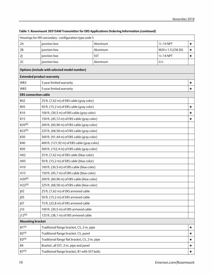
Table 1: Rosemount 3051SAM Transmitter for ERS Applications Ordering Information (continued)
Housings for ERS secondary - configuration type code S
2A Junction box Aluminum ½–14 NPT ★
2B Junction box Aluminum M20 x 1.5 (CM 20) ★
2J Junction box SST ½–14 NPT ★
2C Junction box Aluminum G½
Options (include with selected model number)
Extended product warranty
WR3 3-year limited warranty ★
WR5 5-year limited warranty ★
ERS connection cable
R02 25 ft. (7,62 m) of ERS cable (gray color)
R05 50 ft. (15,2 m) of ERS cable (gray color) ★
R10 100 ft. (30,5 m) of ERS cable (gray color) ★
R15 150 ft. (45,72 m) of ERS cable (gray color) ★
R20(8) 200 ft. (60,96 m) of ERS cable (gray color)
R22(9) 225 ft. (68,58 m) of ERS cable (gray color)
R30 300 ft. (91,44 m) of ERS cable (gray color)
R40 400 ft. (121,92 m) of ERS cable (gray color)
R50 500 ft. (152,4 m) of ERS cable (gray color)
H02 25 ft. (7,62 m) of ERS cable (blue color)
H05 50 ft. (15,2 m) of ERS cable (blue color)
H10 100 ft. (30,5 m) of ERS cable (blue color)
H15 150 ft. (45,7 m) of ERS cable (blue color)
H20(8) 200 ft. (60,96 m) of ERS cable (blue color)
H22(9) 225 ft. (68,58 m) of ERS cable (blue color)
J02 25 ft. (7,62 m) of ERS armored cable
J05 50 ft. (15,2 m) of ERS armored cable
J07 75 ft. (22,8 m) of ERS armored cable
J10 100 ft. (30,5 m) of ERS armored cable
J12(9) 125 ft. (38,1 m) of ERS armored cable
Mounting bracket
B1(4) Traditional flange bracket, CS, 2-in. pipe ★
B2(4) Traditional flange bracket, CS, panel ★
B3(4) Traditional flange flat bracket, CS, 2-in. pipe ★
B4 Bracket, all SST, 2-in. pipe and panel ★
B7(4) Traditional flange bracket, B1 with SST bolts ★
November 2018
10 Emerson.com/Rosemount
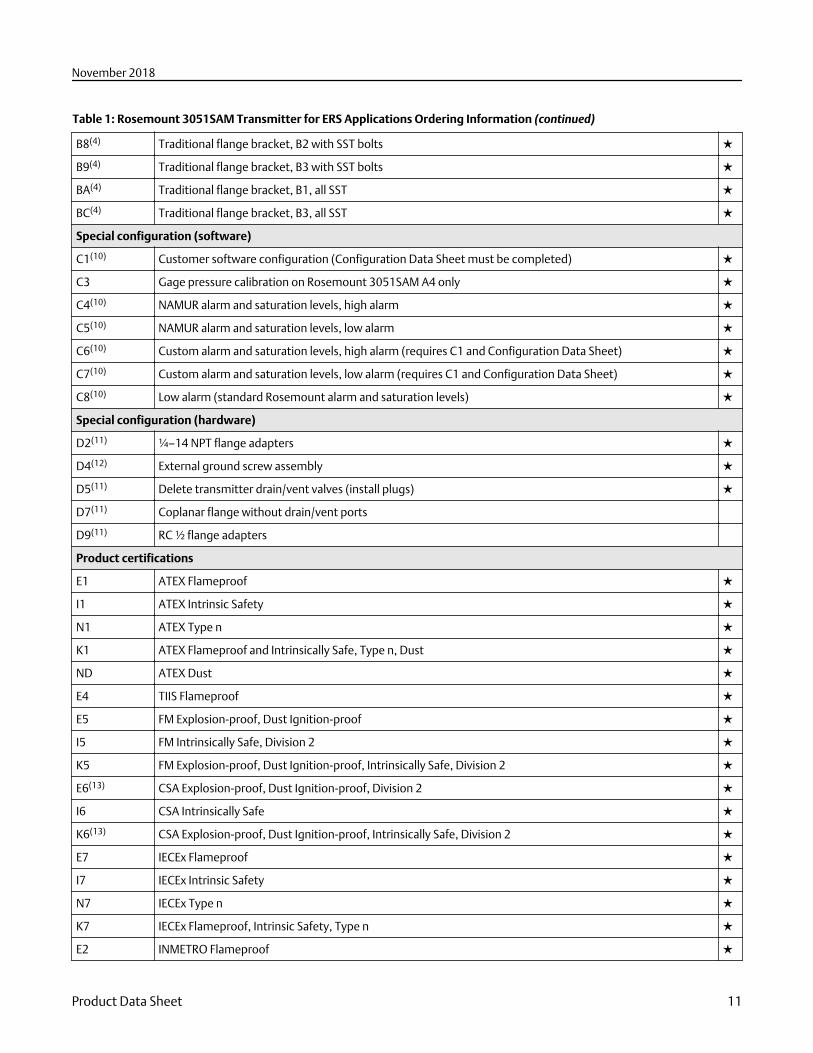
Table 1: Rosemount 3051SAM Transmitter for ERS Applications Ordering Information (continued)
B8(4) Traditional flange bracket, B2 with SST bolts ★
B9(4) Traditional flange bracket, B3 with SST bolts ★
BA(4) Traditional flange bracket, B1, all SST ★
BC(4) Traditional flange bracket, B3, all SST ★
Special configuration (software)
C1(10) Customer software configuration (Configuration Data Sheet must be completed) ★
C3 Gage pressure calibration on Rosemount 3051SAM A4 only ★
C4(10) NAMUR alarm and saturation levels, high alarm ★
C5(10) NAMUR alarm and saturation levels, low alarm ★
C6(10) Custom alarm and saturation levels, high alarm (requires C1 and Configuration Data Sheet) ★
C7(10) Custom alarm and saturation levels, low alarm (requires C1 and Configuration Data Sheet) ★
C8(10) Low alarm (standard Rosemount alarm and saturation levels) ★
Special configuration (hardware)
D2(11) ¼–14 NPT flange adapters ★
D4(12) External ground screw assembly ★
D5(11) Delete transmitter drain/vent valves (install plugs) ★
D7(11) Coplanar flange without drain/vent ports
D9(11) RC ½ flange adapters
Product certifications
E1 ATEX Flameproof ★
I1 ATEX Intrinsic Safety ★
N1 ATEX Type n ★
K1 ATEX Flameproof and Intrinsically Safe, Type n, Dust ★
ND ATEX Dust ★
E4 TIIS Flameproof ★
E5 FM Explosion-proof, Dust Ignition-proof ★
I5 FM Intrinsically Safe, Division 2 ★
K5 FM Explosion-proof, Dust Ignition-proof, Intrinsically Safe, Division 2 ★
E6(13) CSA Explosion-proof, Dust Ignition-proof, Division 2 ★
I6 CSA Intrinsically Safe ★
K6(13) CSA Explosion-proof, Dust Ignition-proof, Intrinsically Safe, Division 2 ★
E7 IECEx Flameproof ★
I7 IECEx Intrinsic Safety ★
N7 IECEx Type n ★
K7 IECEx Flameproof, Intrinsic Safety, Type n ★
E2 INMETRO Flameproof ★
November 2018
Product Data Sheet 11
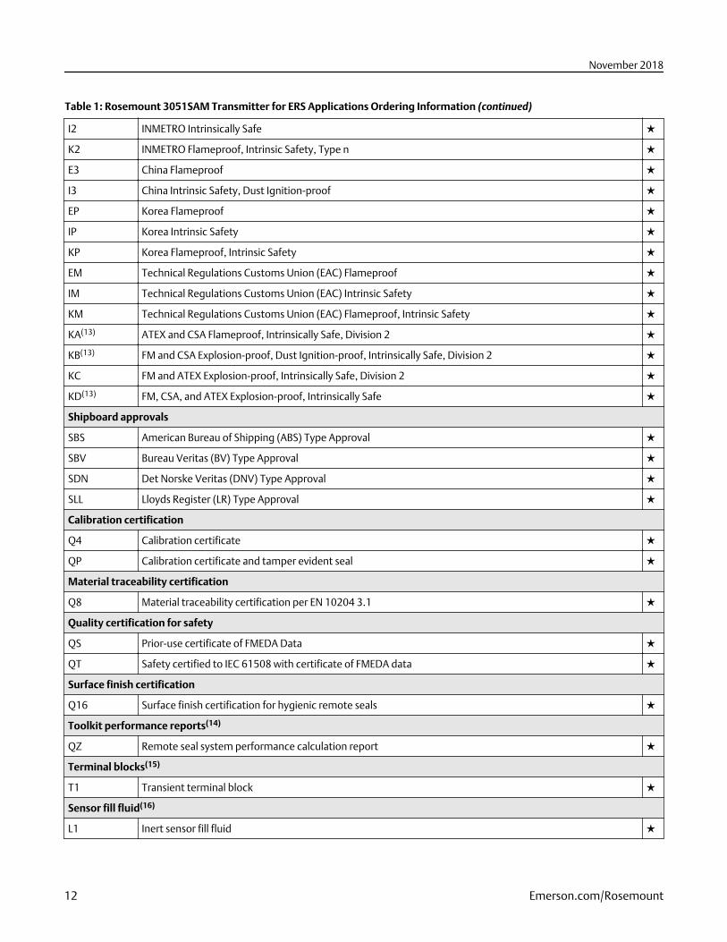
Table 1: Rosemount 3051SAM Transmitter for ERS Applications Ordering Information (continued)
I2 INMETRO Intrinsically Safe ★
K2 INMETRO Flameproof, Intrinsic Safety, Type n ★
E3 China Flameproof ★
I3 China Intrinsic Safety, Dust Ignition-proof ★
EP Korea Flameproof ★
IP Korea Intrinsic Safety ★
KP Korea Flameproof, Intrinsic Safety ★
EM Technical Regulations Customs Union (EAC) Flameproof ★
IM Technical Regulations Customs Union (EAC) Intrinsic Safety ★
KM Technical Regulations Customs Union (EAC) Flameproof, Intrinsic Safety ★
KA(13) ATEX and CSA Flameproof, Intrinsically Safe, Division 2 ★
KB(13) FM and CSA Explosion-proof, Dust Ignition-proof, Intrinsically Safe, Division 2 ★
KC FM and ATEX Explosion-proof, Intrinsically Safe, Division 2 ★
KD(13) FM, CSA, and ATEX Explosion-proof, Intrinsically Safe ★
Shipboard approvals
SBS American Bureau of Shipping (ABS) Type Approval ★
SBV Bureau Veritas (BV) Type Approval ★
SDN Det Norske Veritas (DNV) Type Approval ★
SLL Lloyds Register (LR) Type Approval ★
Calibration certification
Q4 Calibration certificate ★
QP Calibration certificate and tamper evident seal ★
Material traceability certification
Q8 Material traceability certification per EN 10204 3.1 ★
Quality certification for safety
QS Prior-use certificate of FMEDA Data ★
QT Safety certified to IEC 61508 with certificate of FMEDA data ★
Surface finish certification
Q16 Surface finish certification for hygienic remote seals ★
Toolkit performance reports(14)
QZ Remote seal system performance calculation report ★
Terminal blocks(15)
T1 Transient terminal block ★
Sensor fill fluid(16)
L1 Inert sensor fill fluid ★
November 2018
12 Emerson.com/Rosemount
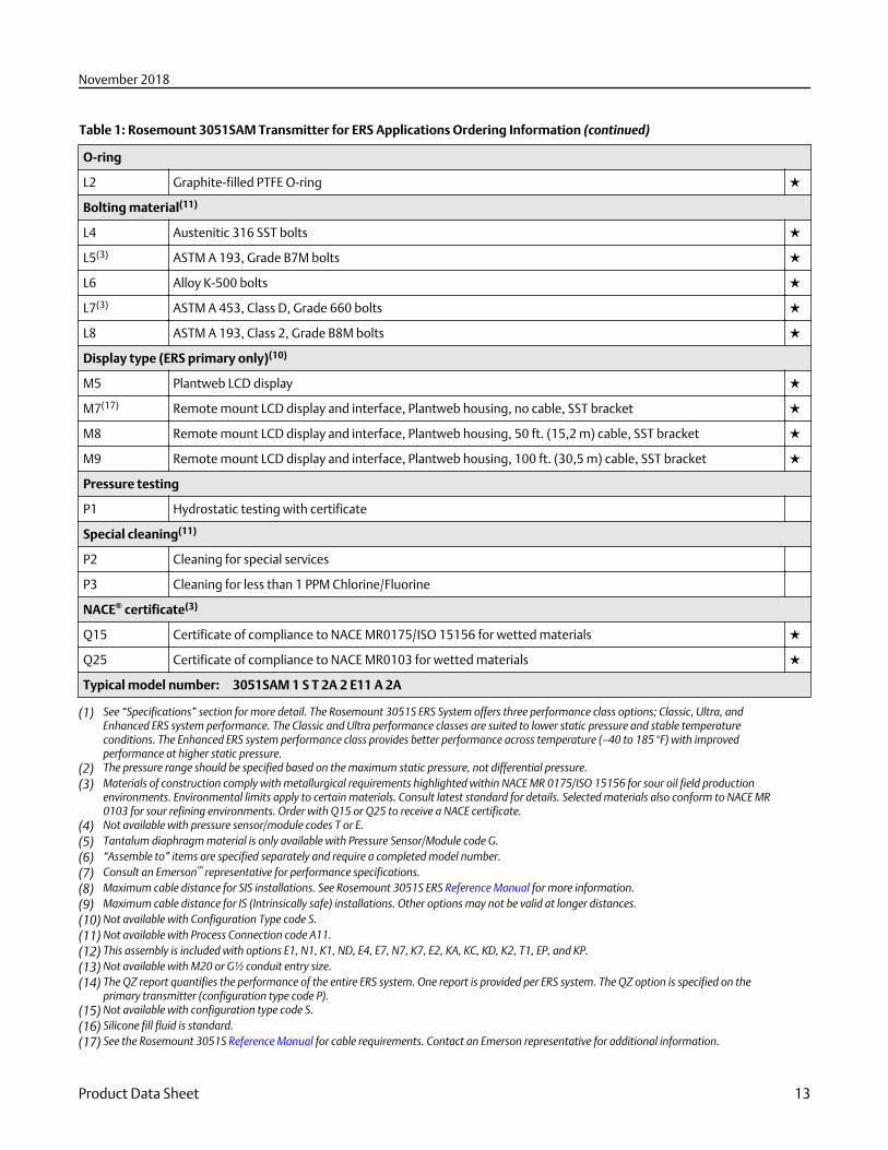
Table 1: Rosemount 3051SAM Transmitter for ERS Applications Ordering Information (continued)
O-ring
L2 Graphite-filled PTFE O-ring ★
Bolting material(11)
L4 Austenitic 316 SST bolts ★
L5(3) ASTM A 193, Grade B7M bolts ★
L6 Alloy K-500 bolts ★
L7(3) ASTM A 453, Class D, Grade 660 bolts ★
L8 ASTM A 193, Class 2, Grade B8M bolts ★
Display type (ERS primary only)(10)
M5 Plantweb LCD display ★
M7(17) Remote mount LCD display and interface, Plantweb housing, no cable, SST bracket ★
M8 Remote mount LCD display and interface, Plantweb housing, 50 ft. (15,2 m) cable, SST bracket ★
M9 Remote mount LCD display and interface, Plantweb housing, 100 ft. (30,5 m) cable, SST bracket ★
Pressure testing
P1 Hydrostatic testing with certificate
Special cleaning(11)
P2 Cleaning for special services
P3 Cleaning for less than 1 PPM Chlorine/Fluorine
NACE® certificate(3)
Q15 Certificate of compliance to NACE MR0175/ISO 15156 for wetted materials ★
Q25 Certificate of compliance to NACE MR0103 for wetted materials ★
Typical model number: 3051SAM 1 S T 2A 2 E11 A 2A
(1) See “Specifications” section for more detail. The Rosemount 3051S ERS System offers three performance class options; Classic, Ultra, andEnhanced ERS system performance. The Classic and Ultra performance classes are suited to lower static pressure and stable temperatureconditions. The Enhanced ERS system performance class provides better performance across temperature (–40 to 185 °F) with improvedperformance at higher static pressure.
(2) The pressure range should be specified based on the maximum static pressure, not differential pressure.(3) Materials of construction comply with metallurgical requirements highlighted within NACE MR 0175/ISO 15156 for sour oil field production
environments. Environmental limits apply to certain materials. Consult latest standard for details. Selected materials also conform to NACE MR0103 for sour refining environments. Order with Q15 or Q25 to receive a NACE certificate.
(4) Not available with pressure sensor/module codes T or E.(5) Tantalum diaphragm material is only available with Pressure Sensor/Module code G.(6) “Assemble to” items are specified separately and require a completed model number.(7) Consult an Emerson™ representative for performance specifications.(8) Maximum cable distance for SIS installations. See Rosemount 3051S ERS Reference Manual for more information.(9) Maximum cable distance for IS (Intrinsically safe) installations. Other options may not be valid at longer distances.(10) Not available with Configuration Type code S.(11) Not available with Process Connection code A11.(12) This assembly is included with options E1, N1, K1, ND, E4, E7, N7, K7, E2, KA, KC, KD, K2, T1, EP, and KP.(13) Not available with M20 or G½ conduit entry size.(14) The QZ report quantifies the performance of the entire ERS system. One report is provided per ERS system. The QZ option is specified on the
primary transmitter (configuration type code P).(15) Not available with configuration type code S.(16) Silicone fill fluid is standard.(17) See the Rosemount 3051S Reference Manual for cable requirements. Contact an Emerson representative for additional information.
November 2018
Product Data Sheet 13
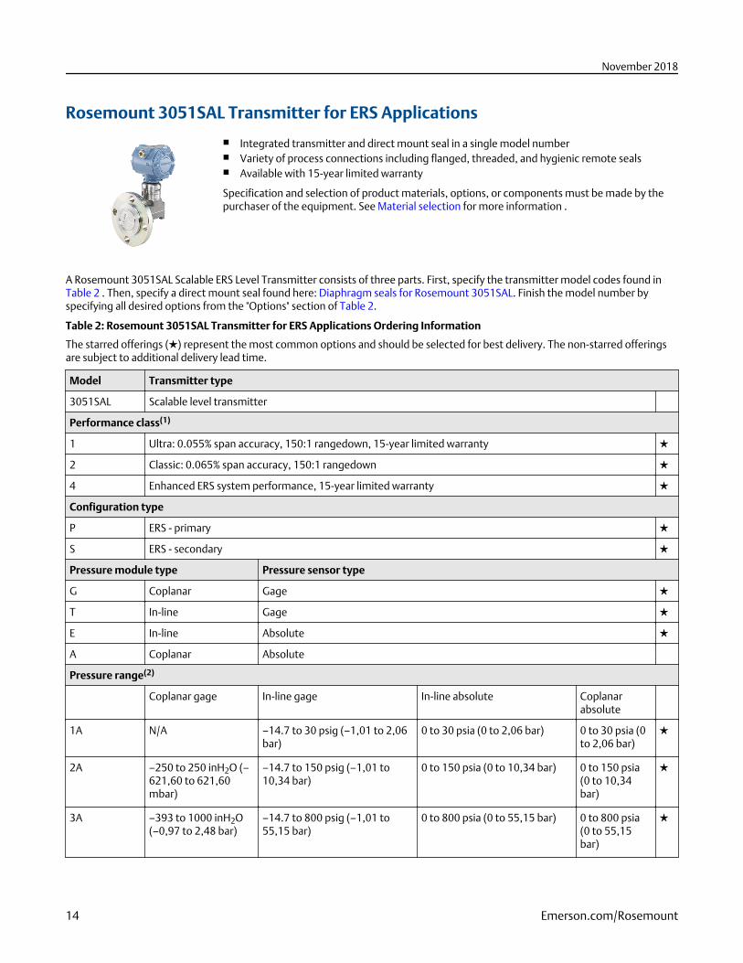
Rosemount 3051SAL Transmitter for ERS Applications
■ Integrated transmitter and direct mount seal in a single model number■ Variety of process connections including flanged, threaded, and hygienic remote seals■ Available with 15-year limited warranty
Specification and selection of product materials, options, or components must be made by thepurchaser of the equipment. See Material selection for more information .
A Rosemount 3051SAL Scalable ERS Level Transmitter consists of three parts. First, specify the transmitter model codes found inTable 2 . Then, specify a direct mount seal found here: Diaphragm seals for Rosemount 3051SAL. Finish the model number byspecifying all desired options from the "Options" section of Table 2.
Table 2: Rosemount 3051SAL Transmitter for ERS Applications Ordering Information
The starred offerings (★) represent the most common options and should be selected for best delivery. The non-starred offeringsare subject to additional delivery lead time.
Model Transmitter type
3051SAL Scalable level transmitter
Performance class(1)
1 Ultra: 0.055% span accuracy, 150:1 rangedown, 15-year limited warranty ★
2 Classic: 0.065% span accuracy, 150:1 rangedown ★
4 Enhanced ERS system performance, 15-year limited warranty ★
Configuration type
P ERS - primary ★
S ERS - secondary ★
Pressure module type Pressure sensor type
G Coplanar Gage ★
T In-line Gage ★
E In-line Absolute ★
A Coplanar Absolute
Pressure range(2)
Coplanar gage In-line gage In-line absolute Coplanarabsolute
1A N/A –14.7 to 30 psig (–1,01 to 2,06bar)
0 to 30 psia (0 to 2,06 bar) 0 to 30 psia (0to 2,06 bar)
★
2A –250 to 250 inH2O (–621,60 to 621,60mbar)
–14.7 to 150 psig (–1,01 to10,34 bar)
0 to 150 psia (0 to 10,34 bar) 0 to 150 psia(0 to 10,34bar)
★
3A –393 to 1000 inH2O(–0,97 to 2,48 bar)
–14.7 to 800 psig (–1,01 to55,15 bar)
0 to 800 psia (0 to 55,15 bar) 0 to 800 psia(0 to 55,15bar)
★
November 2018
14 Emerson.com/Rosemount
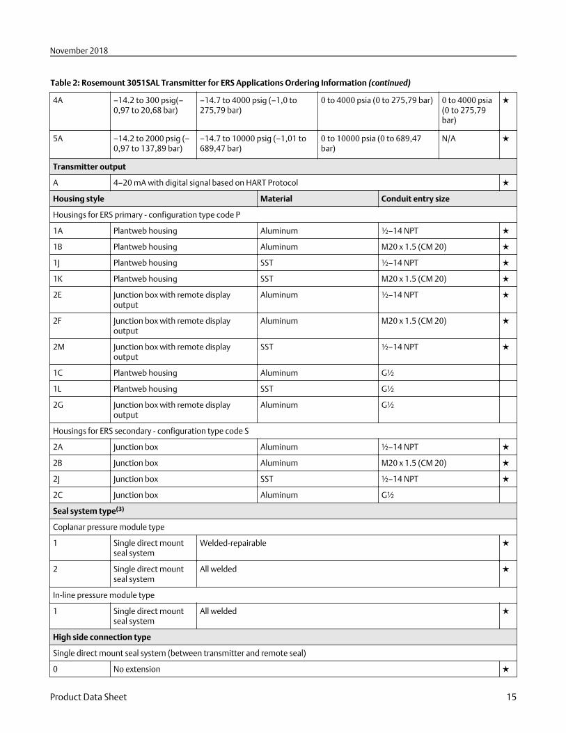
Table 2: Rosemount 3051SAL Transmitter for ERS Applications Ordering Information (continued)
4A –14.2 to 300 psig(–0,97 to 20,68 bar)
–14.7 to 4000 psig (–1,0 to275,79 bar)
0 to 4000 psia (0 to 275,79 bar) 0 to 4000 psia(0 to 275,79bar)
★
5A –14.2 to 2000 psig (–0,97 to 137,89 bar)
–14.7 to 10000 psig (–1,01 to689,47 bar)
0 to 10000 psia (0 to 689,47bar)
N/A ★
Transmitter output
A 4–20 mA with digital signal based on HART Protocol ★
Housing style Material Conduit entry size
Housings for ERS primary - configuration type code P
1A Plantweb housing Aluminum ½–14 NPT ★
1B Plantweb housing Aluminum M20 x 1.5 (CM 20) ★
1J Plantweb housing SST ½–14 NPT ★
1K Plantweb housing SST M20 x 1.5 (CM 20) ★
2E Junction box with remote displayoutput
Aluminum ½–14 NPT ★
2F Junction box with remote displayoutput
Aluminum M20 x 1.5 (CM 20) ★
2M Junction box with remote displayoutput
SST ½–14 NPT ★
1C Plantweb housing Aluminum G½
1L Plantweb housing SST G½
2G Junction box with remote displayoutput
Aluminum G½
Housings for ERS secondary - configuration type code S
2A Junction box Aluminum ½–14 NPT ★
2B Junction box Aluminum M20 x 1.5 (CM 20) ★
2J Junction box SST ½–14 NPT ★
2C Junction box Aluminum G½
Seal system type(3)
Coplanar pressure module type
1 Single direct mountseal system
Welded-repairable ★
2 Single direct mountseal system
All welded ★
In-line pressure module type
1 Single direct mountseal system
All welded ★
High side connection type
Single direct mount seal system (between transmitter and remote seal)
0 No extension ★
November 2018
Product Data Sheet 15
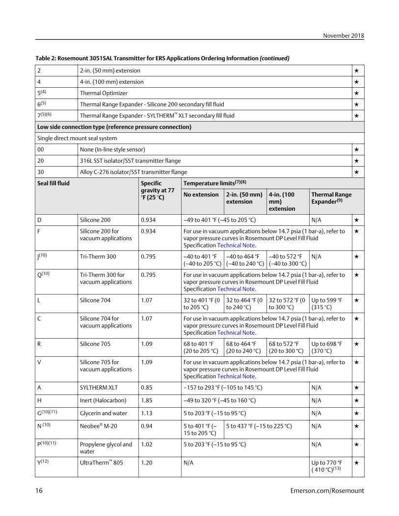
Table 2: Rosemount 3051SAL Transmitter for ERS Applications Ordering Information (continued)
2 2-in. (50 mm) extension ★
4 4-in. (100 mm) extension ★
5(4) Thermal Optimizer ★
6(5) Thermal Range Expander - Silicone 200 secondary fill fluid ★
7(5)(6) Thermal Range Expander - SYLTHERM™ XLT secondary fill fluid ★
Low side connection type (reference pressure connection)
Single direct mount seal system
00 None (In-line style sensor) ★
20 316L SST isolator/SST transmitter flange ★
30 Alloy C-276 isolator/SST transmitter flange ★
Seal fill fluid Specificgravity at 77°F (25 °C)
Temperature limits(7)(8)
No extension 2-in. (50 mm)extension
4-in. (100mm)extension
Thermal RangeExpander(9)
D Silicone 200 0.934 –49 to 401 °F (–45 to 205 °C) N/A ★
F Silicone 200 forvacuum applications
0.934 For use in vacuum applications below 14.7 psia (1 bar-a), refer tovapor pressure curves in Rosemount DP Level Fill FluidSpecification Technical Note.
★
J(10) Tri-Therm 300 0.795 –40 to 401 °F(–40 to 205 °C)
–40 to 464 °F(–40 to 240 °C)
–40 to 572 °F(–40 to 300 °C)
N/A ★
Q(10) Tri-Therm 300 forvacuum applications
0.795 For use in vacuum applications below 14.7 psia (1 bar-a), refer tovapor pressure curves in Rosemount DP Level Fill FluidSpecification Technical Note.
★
L Silicone 704 1.07 32 to 401 °F (0to 205 °C)
32 to 464 °F (0to 240 °C)
32 to 572 °F (0to 300 °C)
Up to 599 °F(315 °C)
★
C Silicone 704 forvacuum applications
1.07 For use in vacuum applications below 14.7 psia (1 bar-a), refer tovapor pressure curves in Rosemount DP Level Fill FluidSpecification Technical Note.
★
R Silicone 705 1.09 68 to 401 °F(20 to 205 °C)
68 to 464 °F(20 to 240 °C)
68 to 572 °F(20 to 300 °C)
Up to 698 °F(370 °C)
★
V Silicone 705 forvacuum applications
1.09 For use in vacuum applications below 14.7 psia (1 bar-a), refer tovapor pressure curves in Rosemount DP Level Fill FluidSpecification Technical Note.
★
A SYLTHERM XLT 0.85 –157 to 293 °F (–105 to 145 °C) N/A ★
H Inert (Halocarbon) 1.85 –49 to 320 °F (–45 to 160 °C) N/A ★
G(10)(11) Glycerin and water 1.13 5 to 203 °F (–15 to 95 °C) N/A ★
N (10) Neobee® M-20 0.94 5 to 401 °F (–15 to 205 °C)
5 to 437 °F (–15 to 225 °C) N/A ★
P(10)(11) Propylene glycol andwater
1.02 5 to 203 °F (–15 to 95 °C) N/A ★
Y(12) UltraTherm™ 805 1.20 N/A Up to 770 °F( 410 °C)(13)
★
November 2018
16 Emerson.com/Rosemount
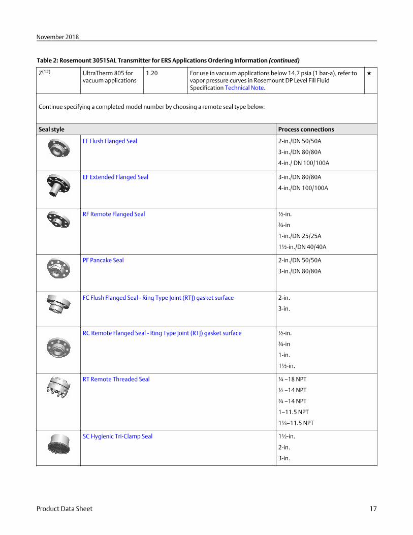
Table 2: Rosemount 3051SAL Transmitter for ERS Applications Ordering Information (continued)
Z(12) UltraTherm 805 forvacuum applications
1.20 For use in vacuum applications below 14.7 psia (1 bar-a), refer tovapor pressure curves in Rosemount DP Level Fill FluidSpecification Technical Note.
★
Continue specifying a completed model number by choosing a remote seal type below:
Seal style Process connections
FF Flush Flanged Seal 2-in./DN 50/50A
3-in./DN 80/80A
4-in./ DN 100/100A
EF Extended Flanged Seal 3-in./DN 80/80A
4-in./DN 100/100A
RF Remote Flanged Seal ½-in.
¾-in
1-in./DN 25/25A
1½-in./DN 40/40A
PF Pancake Seal 2-in./DN 50/50A
3-in./DN 80/80A
FC Flush Flanged Seal - Ring Type Joint (RTJ) gasket surface 2-in.
3-in.
RC Remote Flanged Seal - Ring Type Joint (RTJ) gasket surface ½-in.
¾-in
1-in.
1½-in.
RT Remote Threaded Seal ¼ –18 NPT
½ –14 NPT
¾ –14 NPT
1–11.5 NPT
1¼–11.5 NPT
SC Hygienic Tri-Clamp Seal 1½-in.
2-in.
3-in.
November 2018
Product Data Sheet 17
Table 2: Rosemount 3051SAL Transmitter for ERS Applications Ordering Information (continued)
SS Hygienic Tank Spud Seal 4-in.
Options (include with selected model number)
Extended product warranty
WR3 3-year limited warranty ★
WR5 5-year limited warranty ★
ERS connection cable(14)
R02 25 ft. (7,62 m) of ERS cable (gray color)
R05 50 ft. (15,2 m) of ERS cable (gray color) ★
R10 100 ft. (30,5 m) of ERS cable (gray color) ★
R15 150 ft. (45,72 m) of ERS cable (gray color) ★
R20(15) 200 ft. (60,96 m) of ERS cable (gray color)
R22(16) 225 ft. (68,58 m) of ERS cable (gray color)
R30 300 ft. (91,44 m) of ERS cable (gray color)
R40 400 ft. (121,92 m) of ERS cable (gray color)
R50 500 ft. (152,4 m) of ERS cable (gray color)
H02 25 ft. (7,62 m) of ERS cable (blue color)
H05 50 ft. (15,2 m) of ERS cable (blue color)
H10 100 ft. (30,5 m) of ERS cable (blue color)
H15 150 ft. (45,7 m) of ERS cable (blue color)
H20(15) 200 ft. (60,96 m) of ERS cable (blue color)
H22(16) 225 ft. (68,58 m) of ERS cable (blue color)
J02 25 ft. (7,62 m) of armored ERS cable
J05 50 ft. (15,2 m) of armored ERS cable
J07 75 ft. (22,8 m) of armored ERS cable
J10 100 ft. (30,5 m) of armored ERS cable
J12(16) 125 ft. (38,1 m) of armored ERS cable
Software configuration(17)
C1 Custom software configuration (requires Configuration Data Sheet) ★
Gage pressure calibration
C3 Gage pressure calibration on Rosemount 3051SAL A4 only ★
Alarm limit(17)
C4 NAMUR alarm and saturation levels, high alarm ★
C5 NAMUR alarm and saturation levels, low alarm ★
November 2018
18 Emerson.com/Rosemount
Table 2: Rosemount 3051SAL Transmitter for ERS Applications Ordering Information (continued)
C6 Custom alarm and saturation levels, high alarm (requires C1 and Configuration Data Sheet) ★
C7 Custom alarm and saturation levels, low alarm (requires C1 and Configuration Data Sheet) ★
C8 Low alarm (standard Rosemount alarm and saturation levels) ★
Ground screw(18)
D4 External ground screw assembly ★
Conduit plug
DO 316 SST conduit plug ★
Product certifications
E1 ATEX Flameproof ★
I1 ATEX Intrinsic Safety ★
N1 ATEX Type n ★
K1 ATEX Flameproof and Intrinsically Safe, Type n, Dust ★
ND ATEX Dust ★
E4 TIIS Flameproof ★
E5 FM Explosion-proof, Dust Ignition-proof ★
I5 FM Intrinsically Safe, Division 2 ★
K5 FM Explosion-proof, Dust Ignition-proof, Intrinsically Safe, Division 2 ★
E6(19) CSA Explosion-proof, Dust Ignition-proof, Division 2 ★
I6 CSA Intrinsically Safe ★
K6(19) CSA Explosion-proof, Dust Ignition-proof, Intrinsically Safe, Division 2 ★
E7 IECEx Flameproof ★
I7 IECEx Intrinsic Safety ★
N7 IECEx Type n ★
K7 IECEx Flameproof, Intrinsic Safety, Type n ★
E2 INMETRO Flameproof ★
I2 INMETRO Intrinsically Safe ★
K2 INMETRO Flameproof, Intrinsic Safety, Type n ★
EP Korea Flameproof ★
E3 China Flameproof ★
I3 China Intrinsic Safety, Dust Ignition-proof ★
IP Korea Intrinsic Safety ★
KP Korea Flameproof, Intrinsic Safety ★
EM Technical Regulations Customs Union (EAC) Flameproof ★
IM Technical Regulations Customs Union (EAC) Intrinsic Safety ★
IN Technical Regulations Customs Union (EAC) FISCO Intrinsic Safety ★
KM Technical Regulations Customs Union (EAC) Flameproof, Intrinsic Safety ★
November 2018
Product Data Sheet 19
Table 2: Rosemount 3051SAL Transmitter for ERS Applications Ordering Information (continued)
KA(19) ATEX and CSA Flameproof, Intrinsically Safe, Division 2 ★
KB(19) FM and CSA Explosion-proof, Dust Ignition-proof, Intrinsically Safe, Division 2 ★
KC FM and ATEX Explosion-proof, Intrinsically Safe, Division 2 ★
KD(19) FM, CSA, and ATEX Explosion-proof, Intrinsically Safe ★
Shipboard approvals
SBS American Bureau of Shipping (ABS) Type Approval ★
SBV Bureau Veritas (BV) Type Approval ★
SDN Det Norske Veritas (DNV) Type Approval ★
SLL Lloyds Register (LR) Type Approval ★
Sensor fill fluid(20)
L1 Inert sensor fill fluid ★
O-ring
L2 Graphite-filled PTFE O-ring ★
Bolting material
L4 Austenitic 316 SST bolts ★
Display type (ERS primary only)(17)
M5 Plantweb LCD display ★
M7(21) Remote mount LCD display and interface, Plantweb housing, no cable, SST bracket ★
M8 Remote mount LCD display and interface, Plantweb housing, 50 ft. (15,2 m) cable, SST bracket ★
M9 Remote mount LCD display and interface, Plantweb housing, 100 ft. (30,5 m) cable, SST bracket ★
Pressure testing
P1 Hydrostatic testing with certificate
Special cleaning
P2 Cleaning for special services
P3 Cleaning for Less than 1 PPM Chlorine/Fluorine
Calibration certification
Q4 Calibration certificate ★
QP Calibration certificate with tamper evident seal ★
Material traceability certification
Q8 Material traceability certification per EN 10204 3.1 ★
Quality certification for safety
QS Prior-use certificate of FMEDA Data ★
QT Safety certified to IEC 61508 with certificate of FMEDA data ★
Toolkit performance reports(22)
QZ Remote seal system performance calculation report ★
November 2018
20 Emerson.com/Rosemount
Table 2: Rosemount 3051SAL Transmitter for ERS Applications Ordering Information (continued)
Transient protection(17)
T1 Transient terminal block ★
NACE® certificate(23)
Q15 Certificate of compliance to NACE MR0175/ISO 15156 for wetted materials ★
Q25 Certificate of compliance to NACE MR0103 for wetted materials ★
Typical model number: 3051SAL 1 P G 4A A 1A 1 0 20 D FF 7 1 DA 0 0 M5
(1) See “Specifications” section for more detail. The Rosemount 3051S ERS System offer three performance class options; Classic, Ultra, andEnhanced ERS system performance. The Classic and Ultra performance classes are suited to lower static pressure and stable temperatureconditions. The Enhanced ERS system performance class provides better performance across temperature (–40 to 185 °F) with improvedperformance at higher static pressure.
(2) Not suitable for vacuum applications.(3) See Seal system type in Rosemount DP Level Product Data Sheet for more detail.(4) Maximum working pressure (MWP) of the Thermal Optimizer is 4000 psi (275 bar). See Figure 6, Figure 7, or Table 52 for Thermal Optimizer
temperature limits.(5) Maximum working pressure (MWP) of the Thermal Range Expander is 3750 psi (258,6 bar).(6) Thermal Range Expander with SYLTHERM XLT secondary fill fluid is not recommended for use in vacuum applications below 6 psia (400 mbar-a).(7) At ambient pressure of 14.7 psia (1 bar-a) and ambient temperature of 70 °F (21 °C). Temperature limits are reduced in vacuum service and may
be limited by seal selection.(8) Due to heat transfer to the transmitter, the maximum process temperature of the transmitter will be de-rated if ambient or process temperatures
exceed 185 °F (85 °C). Consult Instrument Toolkit™ to verify the application.(9) For complete process and ambient temperature limits, see Thermal Range Expander temperature operating range.(10) This is a food grade fill fluid.(11) Not suitable for vacuum applications.(12) Only available with Thermal Range Expander.(13) UltraTherm 805 supports maximum design temperature of 454 °C (850 °F). Design temperature rating is for non-continuous use with a
cumulative exposure time less of than 12 hours.(14) The pressure range should be specified based on the maximum static pressure, not differential pressure.(15) Maximum cable distance for SIS installations. See "Safety Instrumented Systems (SIS) Certification" section of Rosemount 3051S ERS Reference
Manual for more information.(16) Maximum cable distance for IS (Intrinsically safe) installations. Other options may not be valid at longer distances.(17) Not available with configuration type code S.(18) This assembly is included with options EP, KP, E1, N1, K1, ND, E4, E7, N7, K7, E2, KA, KC, KD, K2, T1, E3, EM, KM.(19) Not available with M20 or G½ conduit entry size.(20) Silicone fill fluid is standard.(21) See the Rosemount 3051S Reference Manual for cable requirements. Contact an Emerson representative for additional information.(22) The QZ report quantifies the performance of the entire ERS system. One report is provided per ERS system. The QZ option is specified on the
primary transmitter (configuration type code P).(23) Materials of construction comply with metallurgical requirements highlighted within NACE MR 0175/ISO 15156 for sour oil field production
environments. Environmental limits apply to certain materials. Consult latest standard for details. Selected materials also conform to NACE MR0103 for sour refining environments. UltraTherm 805 supports maximum design temperature of 850 °F (454 °C). Design temperature rating is fornon-continuous use with a cumulative exposure time less of than 12 hours.
November 2018
Product Data Sheet 21
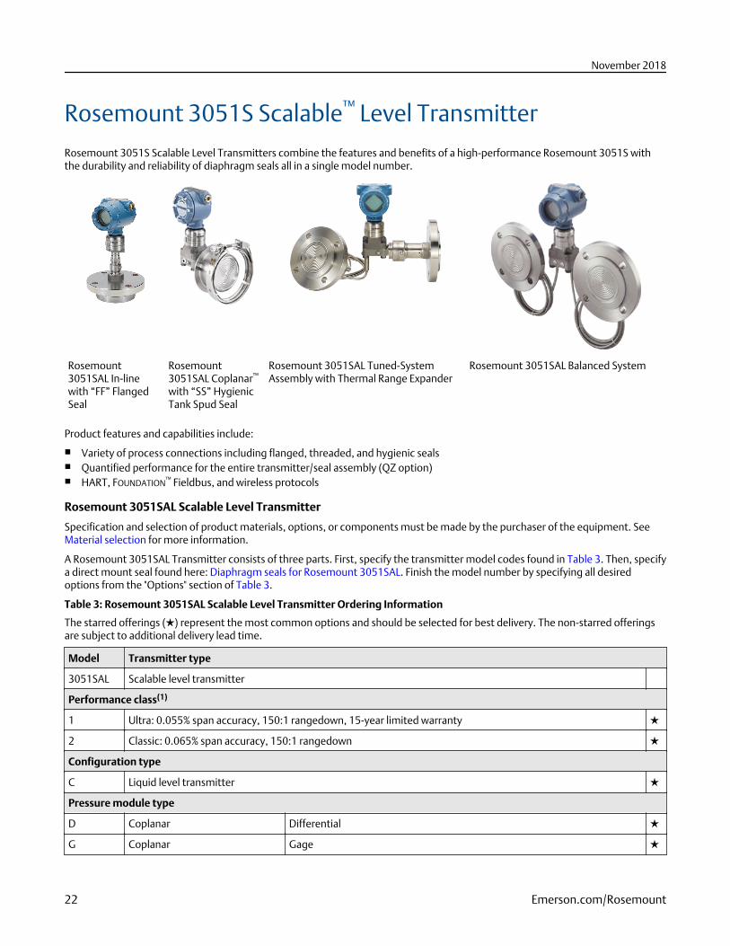
Rosemount 3051S Scalable™ Level TransmitterRosemount 3051S Scalable Level Transmitters combine the features and benefits of a high-performance Rosemount 3051S withthe durability and reliability of diaphragm seals all in a single model number.
Rosemount3051SAL In-linewith “FF” FlangedSeal
Rosemount3051SAL Coplanar™
with “SS” HygienicTank Spud Seal
Rosemount 3051SAL Tuned-SystemAssembly with Thermal Range Expander
Rosemount 3051SAL Balanced System
Product features and capabilities include:
■ Variety of process connections including flanged, threaded, and hygienic seals■ Quantified performance for the entire transmitter/seal assembly (QZ option)■ HART, FOUNDATION™ Fieldbus, and wireless protocols
Rosemount 3051SAL Scalable Level Transmitter
Specification and selection of product materials, options, or components must be made by the purchaser of the equipment. SeeMaterial selection for more information.
A Rosemount 3051SAL Transmitter consists of three parts. First, specify the transmitter model codes found in Table 3. Then, specifya direct mount seal found here: Diaphragm seals for Rosemount 3051SAL. Finish the model number by specifying all desiredoptions from the "Options" section of Table 3.
Table 3: Rosemount 3051SAL Scalable Level Transmitter Ordering Information
The starred offerings (★) represent the most common options and should be selected for best delivery. The non-starred offeringsare subject to additional delivery lead time.
Model Transmitter type
3051SAL Scalable level transmitter
Performance class(1)
1 Ultra: 0.055% span accuracy, 150:1 rangedown, 15-year limited warranty ★
2 Classic: 0.065% span accuracy, 150:1 rangedown ★
Configuration type
C Liquid level transmitter ★
Pressure module type
D Coplanar Differential ★
G Coplanar Gage ★
November 2018
22 Emerson.com/Rosemount
Table 3: Rosemount 3051SAL Scalable Level Transmitter Ordering Information (continued)
T In-line Gage ★
E In-line Absolute ★
A Coplanar Absolute
Pressure range
Coplanar DP Coplanar Gage In-line Gage In-line Absolute Coplanar Absolute
1A N/A N/A –14.7 to 30psig (–1,01 to2,06 bar)
0 to 30 psia (0to 2,06 bar)
0 to 30 psia (0 to 2,06 bar) ★
2A –250 to 250inH2O (–621,60 to621,60 mbar)
–250 to 250inH2O (–621,60 to621,60 mbar)
–14.7 to 150psig (–1,01 to10,34 bar)
0 to 150 psia (0to 10,34 bar)
0 to 150 psia (0 to 10,34 bar) ★
3A –1000 to 1000inH2O (–2,48to 2,48 bar)
–393 to 1000inH2O (–0,97to 2,48 bar)
–14.7 to 800psig (–1,01 to55,15 bar)
0 to 800 psia (0to 55,15 bar)
0 to 800 psia (0 to 55,15 bar) ★
4A –300 to 300 psi(–20,68 to20,68 bar)
–14.2 to 300psig (–0,97 to20,68 bar)
–14.7 to 4000psig (–1,01 to275,79 bar)
0 to 4000 psia(0 to 275,79bar)
0 to 4000 psia (0 to 275,79 bar) ★
5A –2000 to 2000psi (–137,89 to137,89 bar)
–14.2 to 2000psig (–0,97 to137,89 bar)
–14.7 to 10000psig (–1,01 to689,47 bar)
0 to 10000 psia(0 to 689,47bar)
N/A ★
Transmitter output
A 4–20 mA with digital signal based on HART protocol ★
F(2) FOUNDATION Fieldbus™ protocol ★
X(3) Wireless (requires wireless options and wireless Plantweb housing) ★
Housing style Material Conduit entry
1A Plantweb housing Aluminum ½–14 NPT ★
1B Plantweb housing Aluminum M20 x 1.5 ★
1J Plantweb housing SST ½–14 NPT ★
1K Plantweb housing SST M20 x 1.5 ★
2A Junction box housing Aluminum ½–14 NPT ★
2B Junction box housing Aluminum M20 x 1.5 ★
2E Junction box with output for remote interface Aluminum ½–14 NPT ★
2F Junction box with output for remote interface Aluminum M20 x 1.5 ★
2J Junction box housing SST ½–14 NPT ★
5A(4) Wireless Plantweb housing Aluminum ½–14 NPT ★
5J(4) Wireless Plantweb housing SST ½–14 NPT ★
7J(5) Quick connect (a size mini, 4-pin maletermination)
SST N/A ★
1C Plantweb housing Aluminum G½
November 2018
Product Data Sheet 23
Table 3: Rosemount 3051SAL Scalable Level Transmitter Ordering Information (continued)
1L Plantweb housing 316L SST G½
2C Junction box housing Aluminum G½
2G Junction box with output for remote interface Aluminum G½
Seal system type
Coplanar pressure module type In-line pressure module type
1 Direct mount single seal system Welded-repairable
Direct mount single sealsystem
Welded- repairable ★
2 Direct mount single seal system All welded N/A N/A ★
3(6) Tuned-system assembly - onedirect mount and one remotemount seal with capillary
Welded-repairable
N/A N/A ★
4(6) Tuned-system assembly - onedirect mount and one remotemount seal with capillary
All welded N/A N/A ★
5(6) Balanced system - two remotemount seals with equal lengthsof capillary
Welded-repairable
N/A N/A ★
6(6) Balanced system - two remotemount seals with equal lengthsof capillary
All welded N/A N/A ★
7 Remote mount single sealsystem with capillary - 316L lowside transmitter isolator
Welded-repairable
Remote mount single sealsystem with capillary
All welded ★
8 Remote mount single sealsystem with capillary - 316L lowside transmitter isolator
All welded N/A N/A ★
9 Remote mount single sealsystem with capillary - AlloyC-276 low side transmitterisolator
Welded-repairable
N/A N/A ★
A Remote mount single sealsystem with capillary - AlloyC-276 low side transmitterisolator
All welded N/A N/A ★
High side connection type (select based on seal system type chosen)
Single seal system Dual seal system
Direct mount Remote mount with capillary Tuned-systemassembly
Balanced system
Coplanar In-line Coplanar In-line Coplanar Coplanar
0 No extension Standard Standard Noextension/Standard
Standard ★
November 2018
24 Emerson.com/Rosemount
Table 3: Rosemount 3051SAL Scalable Level Transmitter Ordering Information (continued)
2 2-in. (50 mm)extension
N/A N/A N/A 2-in. (50mm)extension
N/A ★
4 4-in. (100 mm)extension
4-in. (100 mm)extension (7)
N/A N/A 4-in. (100mm)extension
N/A ★
5 N/A Thermaloptimizer
N/A N/A N/A N/A ★
6(8) Thermal Range Expander -Silicone 200 secondary fill
Thermal Range Expander -Silicone 200 secondary fill fluidsingle capillary
Thermal Range Expander - Silicone 200secondary fill with low side capillary
★
7(8) Thermal Range Expander -SYLTHERM™ XLT secondary fillfluid
Thermal Range Expander -SYLTHERM XLT secondary fillfluid single capillary
Thermal Range Expander - SYLTHERM XLTsecondary fill with low side capillary
★
Low side connection type or capillary I.D.
Material for low side referenceconnection
Capillary I.D.
Direct mount Remote mount with capillary Tuned-systemassembly
Balanced system
Coplanar In-line Coplanar or In-line Coplanar Coplanar
0 N/A No referenceconnection
N/A N/A N/A ★
1(9)(10) Assemble tooneRosemount1199 remoteseal
N/A N/A N/A N/A ★
2 316L SSTisolator andSST transmitterflange
N/A N/A N/A N/A ★
3 Alloy C-276isolator andSST transmitterflange
N/A N/A N/A N/A ★
B N/A N/A 0.03-in. (0,711 mm) ID capillary 0.03-in.(0,711mm) IDcapillary
0.03-in. (0,711 mm) IDcapillary
★
C N/A N/A 0.04-in. (1,092 mm) ID capillary 0.04-in.(1,092mm) IDcapillary
0.04-in. (1,092 mm) IDcapillary
★
D N/A N/A 0.075-in. (1,905 mm) ID capillary 0.075-in.(1,905mm) IDcapillary
0.075-in. (1,905 mm) IDcapillary
★
November 2018
Product Data Sheet 25
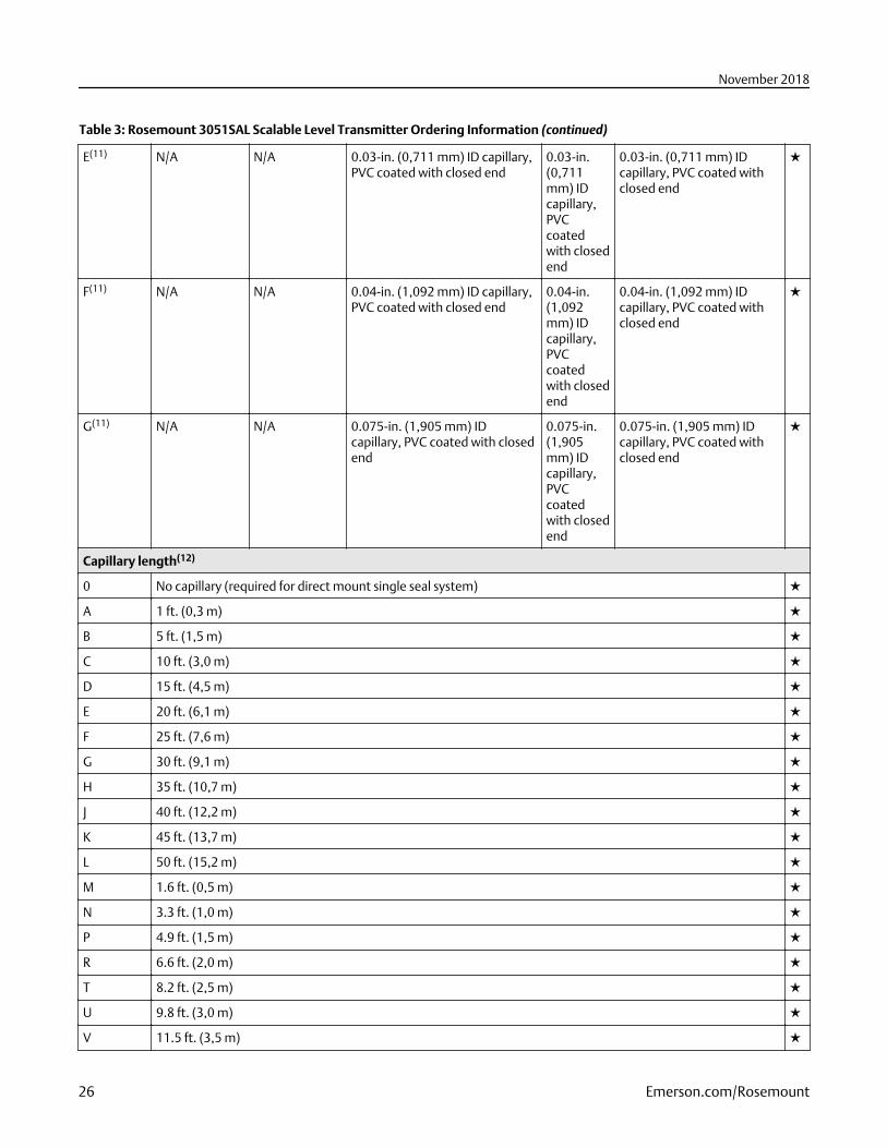
Table 3: Rosemount 3051SAL Scalable Level Transmitter Ordering Information (continued)
E(11) N/A N/A 0.03-in. (0,711 mm) ID capillary,PVC coated with closed end
0.03-in.(0,711mm) IDcapillary,PVCcoatedwith closedend
0.03-in. (0,711 mm) IDcapillary, PVC coated withclosed end
★
F(11) N/A N/A 0.04-in. (1,092 mm) ID capillary,PVC coated with closed end
0.04-in.(1,092mm) IDcapillary,PVCcoatedwith closedend
0.04-in. (1,092 mm) IDcapillary, PVC coated withclosed end
★
G(11) N/A N/A 0.075-in. (1,905 mm) IDcapillary, PVC coated with closedend
0.075-in.(1,905mm) IDcapillary,PVCcoatedwith closedend
0.075-in. (1,905 mm) IDcapillary, PVC coated withclosed end
★
Capillary length(12)
0 No capillary (required for direct mount single seal system) ★
A 1 ft. (0,3 m) ★
B 5 ft. (1,5 m) ★
C 10 ft. (3,0 m) ★
D 15 ft. (4,5 m) ★
E 20 ft. (6,1 m) ★
F 25 ft. (7,6 m) ★
G 30 ft. (9,1 m) ★
H 35 ft. (10,7 m) ★
J 40 ft. (12,2 m) ★
K 45 ft. (13,7 m) ★
L 50 ft. (15,2 m) ★
M 1.6 ft. (0,5 m) ★
N 3.3 ft. (1,0 m) ★
P 4.9 ft. (1,5 m) ★
R 6.6 ft. (2,0 m) ★
T 8.2 ft. (2,5 m) ★
U 9.8 ft. (3,0 m) ★
V 11.5 ft. (3,5 m) ★
November 2018
26 Emerson.com/Rosemount
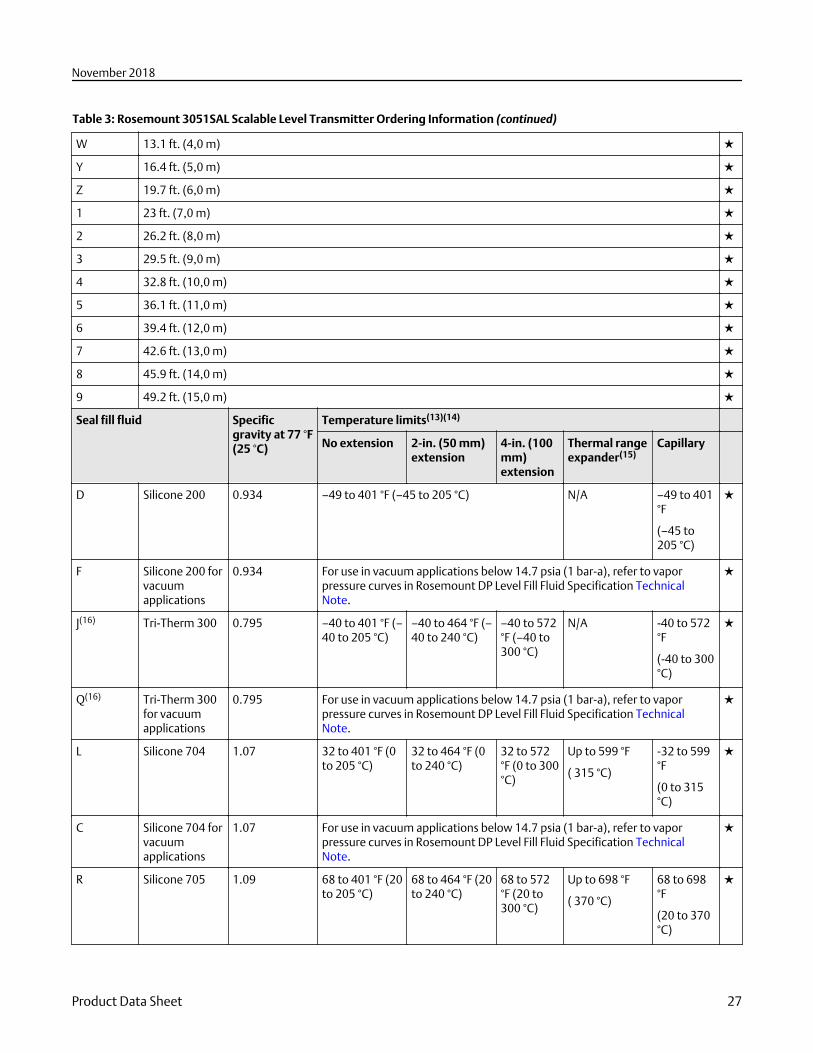
Table 3: Rosemount 3051SAL Scalable Level Transmitter Ordering Information (continued)
W 13.1 ft. (4,0 m) ★
Y 16.4 ft. (5,0 m) ★
Z 19.7 ft. (6,0 m) ★
1 23 ft. (7,0 m) ★
2 26.2 ft. (8,0 m) ★
3 29.5 ft. (9,0 m) ★
4 32.8 ft. (10,0 m) ★
5 36.1 ft. (11,0 m) ★
6 39.4 ft. (12,0 m) ★
7 42.6 ft. (13,0 m) ★
8 45.9 ft. (14,0 m) ★
9 49.2 ft. (15,0 m) ★
Seal fill fluid Specificgravity at 77 °F(25 °C)
Temperature limits(13)(14)
No extension 2-in. (50 mm)extension
4-in. (100mm)extension
Thermal rangeexpander(15)
Capillary
D Silicone 200 0.934 –49 to 401 °F (–45 to 205 °C) N/A –49 to 401°F
(–45 to205 °C)
★
F Silicone 200 forvacuumapplications
0.934 For use in vacuum applications below 14.7 psia (1 bar-a), refer to vaporpressure curves in Rosemount DP Level Fill Fluid Specification TechnicalNote.
★
J(16) Tri-Therm 300 0.795 –40 to 401 °F (–40 to 205 °C)
–40 to 464 °F (–40 to 240 °C)
–40 to 572°F (–40 to300 °C)
N/A -40 to 572°F
(-40 to 300°C)
★
Q(16) Tri-Therm 300for vacuumapplications
0.795 For use in vacuum applications below 14.7 psia (1 bar-a), refer to vaporpressure curves in Rosemount DP Level Fill Fluid Specification TechnicalNote.
★
L Silicone 704 1.07 32 to 401 °F (0to 205 °C)
32 to 464 °F (0to 240 °C)
32 to 572°F (0 to 300°C)
Up to 599 °F
( 315 °C)
-32 to 599°F
(0 to 315°C)
★
C Silicone 704 forvacuumapplications
1.07 For use in vacuum applications below 14.7 psia (1 bar-a), refer to vaporpressure curves in Rosemount DP Level Fill Fluid Specification TechnicalNote.
★
R Silicone 705 1.09 68 to 401 °F (20to 205 °C)
68 to 464 °F (20to 240 °C)
68 to 572°F (20 to300 °C)
Up to 698 °F
( 370 °C)
68 to 698°F
(20 to 370°C)
★
November 2018
Product Data Sheet 27
Table 3: Rosemount 3051SAL Scalable Level Transmitter Ordering Information (continued)
V Silicone 705 forvacuumapplications
1.09 For use in vacuum applications below 14.7 psia (1 bar-a), refer to vaporpressure curves in Rosemount DP Level Fill Fluid Specification TechnicalNote.
★
Y(17) UltraTherm™
8051.20 N/A Up to 770 °F
( 410 °C)(18)N/A ★
Z(17) UltraTherm805 for vacuumapplications
1.20 For use in vacuum applications below 14.7 psia (1 bar-a), refer to vaporpressure curves in Rosemount DP Level Fill Fluid Specification TechnicalNote.
★
A SYLTHERM XLT 0.85 –157 to 293 °F (–105 to 145 °C) N/A -157 to293 °F(-105 to145 °C)
★
H Inert(Halocarbon)
1.85 –49 to 320 °F (–45 to 160 °C) N/A -49 to 320°F (-45 to160 °C)
★
N (16) Neobee® M-20 0.94 5 to 401 °F (–15to 205 °C)
5 to 437 °F (–15 to 225 °C) N/A 5 to 437 °F(-15 to 225°C)
★
G(10)(16) Glycerin andwater
1.13 5 to 203 °F (–15 to 95 °C) N/A 5 to 437 °F(-15 to 225°C)
★
P(10)(16) Propyleneglycol andwater
1.02 5 to 203 °F (–15 to 95 °C) N/A 5 to 203 °F(-15 to 95°C)
★
Continue specifying a completed model number by choosing a remote seal type below:
Seal style Process connections
FF Flush Flanged Seal
2-in./DN 50/ 50A
3-in./DN 80/80A
4 in./DN 100/100A
EF Extended Flanged Seal 3-in./DN 80/80A
4-in./DN 100/100A
Remote Flanged (RF) Seal ½-in.
¾-in.
1-in./DN 25/25A
1½-in./DN 40/40A
PF Pancake Seal 2-in./DN 50/50A
3-in./DN 80/80A
November 2018
28 Emerson.com/Rosemount
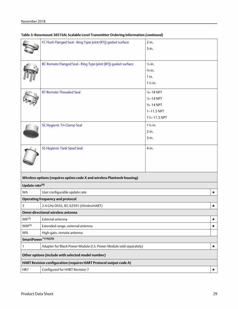
Table 3: Rosemount 3051SAL Scalable Level Transmitter Ordering Information (continued)
FC Flush Flanged Seal - Ring Type Joint (RTJ) gasket surface 2-in.
3-in.
RC Remote Flanged Seal - Ring Type Joint (RTJ) gasket surface ½-in.
¾-in.
1 in.
1½-in.
RT Remote Threaded Seal ¼–18 NPT
½–14 NPT
¾–14 NPT
1–11.5 NPT
1¼–11.5 NPT
SC Hygienic Tri-Clamp Seal 1½-in.
2-in.
3-in.
SS Hygienic Tank Spud Seal 4-in.
Wireless options (requires option code X and wireless Plantweb housing)
Update rate(4)
WA User configurable update rate ★
Operating frequency and protocol
3 2.4 GHz DSSS, IEC 62591 (WirelessHART) ★
Omni-directional wireless antenna
WK(4) External antenna ★
WM(4) Extended range, external antenna ★
WN High-gain, remote antenna
SmartPower™(19)(20)
1 Adapter for Black Power Module (I.S. Power Module sold separately) ★
Other options (include with selected model number)
HART Revision configuration (requires HART Protocol output code A)
HR7 Configured for HART Revision 7 ★
November 2018
Product Data Sheet 29
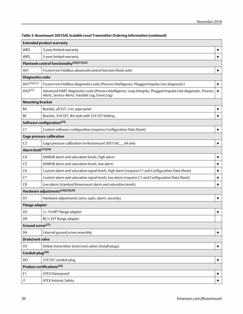
Table 3: Rosemount 3051SAL Scalable Level Transmitter Ordering Information (continued)
Extended product warranty
WR3 3-year limited warranty ★
WR5 5-year limited warranty ★
Plantweb control functionality(20)(21)(22)
A01 FOUNDATION Fieldbus advanced control function block suite ★
Diagnostics suite
D01(20)(21) FOUNDATION Fieldbus diagnostics suite (Process Intelligence, Plugged Impulse Line diagnostic) ★
DA2(23) Advanced HART diagnostics suite (Process Intelligence, Loop Integrity, Plugged Impulse Line diagnostic, ProcessAlerts, Service Alerts, Variable Log, Event Log)
★
Mounting bracket
B4 Bracket, all SST, 2-in. pipe panel ★
BE Bracket, 316 SST, B4-style with 316 SST bolting ★
Software configuration(24)
C1 Custom software configuration (requires Configuration Data Sheet) ★
Gage pressure calibration
C3 Gage pressure calibration on Rosemount 3051SAL_ _A4 only ★
Alarm limit(21)(24)
C4 NAMUR alarm and saturation levels, high alarm ★
C5 NAMUR alarm and saturation levels, low alarm ★
C6 Custom alarm and saturation signal levels, high alarm (requires C1 and Configuration Data Sheet) ★
C7 Custom alarm and saturation signal levels, low alarm (requires C1 and Configuration Data Sheet) ★
C8 Low alarm (standard Rosemount alarm and saturation levels) ★
Hardware adjustments(24)(25)(26)
D1 Hardware adjustments (zero, span, alarm, security) ★
Flange adapter
D2 ½–14 NPT flange adapter ★
D9 RC½ SST flange adapter
Ground screw(27)
D4 External ground screw assembly ★
Drain/vent valve
D5 Delete transmitter drain/vent valves (install plugs) ★
Conduit plug(28)
DO 316 SST conduit plug ★
Product certifications(29)
E1 ATEX Flameproof ★
I1 ATEX Intrinsic Safety ★
November 2018
30 Emerson.com/Rosemount
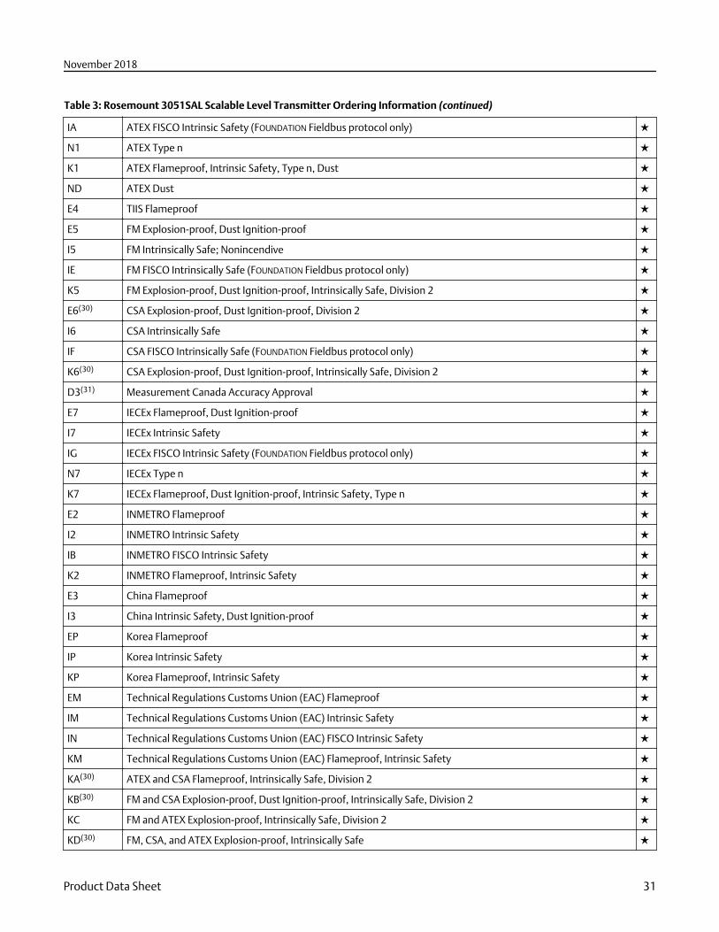
Table 3: Rosemount 3051SAL Scalable Level Transmitter Ordering Information (continued)
IA ATEX FISCO Intrinsic Safety (FOUNDATION Fieldbus protocol only) ★
N1 ATEX Type n ★
K1 ATEX Flameproof, Intrinsic Safety, Type n, Dust ★
ND ATEX Dust ★
E4 TIIS Flameproof ★
E5 FM Explosion-proof, Dust Ignition-proof ★
I5 FM Intrinsically Safe; Nonincendive ★
IE FM FISCO Intrinsically Safe (FOUNDATION Fieldbus protocol only) ★
K5 FM Explosion-proof, Dust Ignition-proof, Intrinsically Safe, Division 2 ★
E6(30) CSA Explosion-proof, Dust Ignition-proof, Division 2 ★
I6 CSA Intrinsically Safe ★
IF CSA FISCO Intrinsically Safe (FOUNDATION Fieldbus protocol only) ★
K6(30) CSA Explosion-proof, Dust Ignition-proof, Intrinsically Safe, Division 2 ★
D3(31) Measurement Canada Accuracy Approval ★
E7 IECEx Flameproof, Dust Ignition-proof ★
I7 IECEx Intrinsic Safety ★
IG IECEx FISCO Intrinsic Safety (FOUNDATION Fieldbus protocol only) ★
N7 IECEx Type n ★
K7 IECEx Flameproof, Dust Ignition-proof, Intrinsic Safety, Type n ★
E2 INMETRO Flameproof ★
I2 INMETRO Intrinsic Safety ★
IB INMETRO FISCO Intrinsic Safety ★
K2 INMETRO Flameproof, Intrinsic Safety ★
E3 China Flameproof ★
I3 China Intrinsic Safety, Dust Ignition-proof ★
EP Korea Flameproof ★
IP Korea Intrinsic Safety ★
KP Korea Flameproof, Intrinsic Safety ★
EM Technical Regulations Customs Union (EAC) Flameproof ★
IM Technical Regulations Customs Union (EAC) Intrinsic Safety ★
IN Technical Regulations Customs Union (EAC) FISCO Intrinsic Safety ★
KM Technical Regulations Customs Union (EAC) Flameproof, Intrinsic Safety ★
KA(30) ATEX and CSA Flameproof, Intrinsically Safe, Division 2 ★
KB(30) FM and CSA Explosion-proof, Dust Ignition-proof, Intrinsically Safe, Division 2 ★
KC FM and ATEX Explosion-proof, Intrinsically Safe, Division 2 ★
KD(30) FM, CSA, and ATEX Explosion-proof, Intrinsically Safe ★
November 2018
Product Data Sheet 31
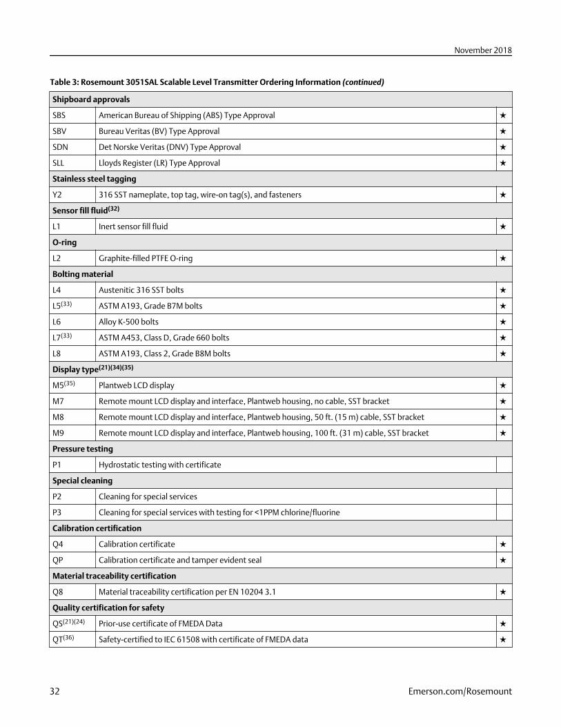
Table 3: Rosemount 3051SAL Scalable Level Transmitter Ordering Information (continued)
Shipboard approvals
SBS American Bureau of Shipping (ABS) Type Approval ★
SBV Bureau Veritas (BV) Type Approval ★
SDN Det Norske Veritas (DNV) Type Approval ★
SLL Lloyds Register (LR) Type Approval ★
Stainless steel tagging
Y2 316 SST nameplate, top tag, wire-on tag(s), and fasteners ★
Sensor fill fluid(32)
L1 Inert sensor fill fluid ★
O-ring
L2 Graphite-filled PTFE O-ring ★
Bolting material
L4 Austenitic 316 SST bolts ★
L5(33) ASTM A193, Grade B7M bolts ★
L6 Alloy K-500 bolts ★
L7(33) ASTM A453, Class D, Grade 660 bolts ★
L8 ASTM A193, Class 2, Grade B8M bolts ★
Display type(21)(34)(35)
M5(35) Plantweb LCD display ★
M7 Remote mount LCD display and interface, Plantweb housing, no cable, SST bracket ★
M8 Remote mount LCD display and interface, Plantweb housing, 50 ft. (15 m) cable, SST bracket ★
M9 Remote mount LCD display and interface, Plantweb housing, 100 ft. (31 m) cable, SST bracket ★
Pressure testing
P1 Hydrostatic testing with certificate
Special cleaning
P2 Cleaning for special services
P3 Cleaning for special services with testing for <1PPM chlorine/fluorine
Calibration certification
Q4 Calibration certificate ★
QP Calibration certificate and tamper evident seal ★
Material traceability certification
Q8 Material traceability certification per EN 10204 3.1 ★
Quality certification for safety
QS(21)(24) Prior-use certificate of FMEDA Data ★
QT(36) Safety-certified to IEC 61508 with certificate of FMEDA data ★
November 2018
32 Emerson.com/Rosemount
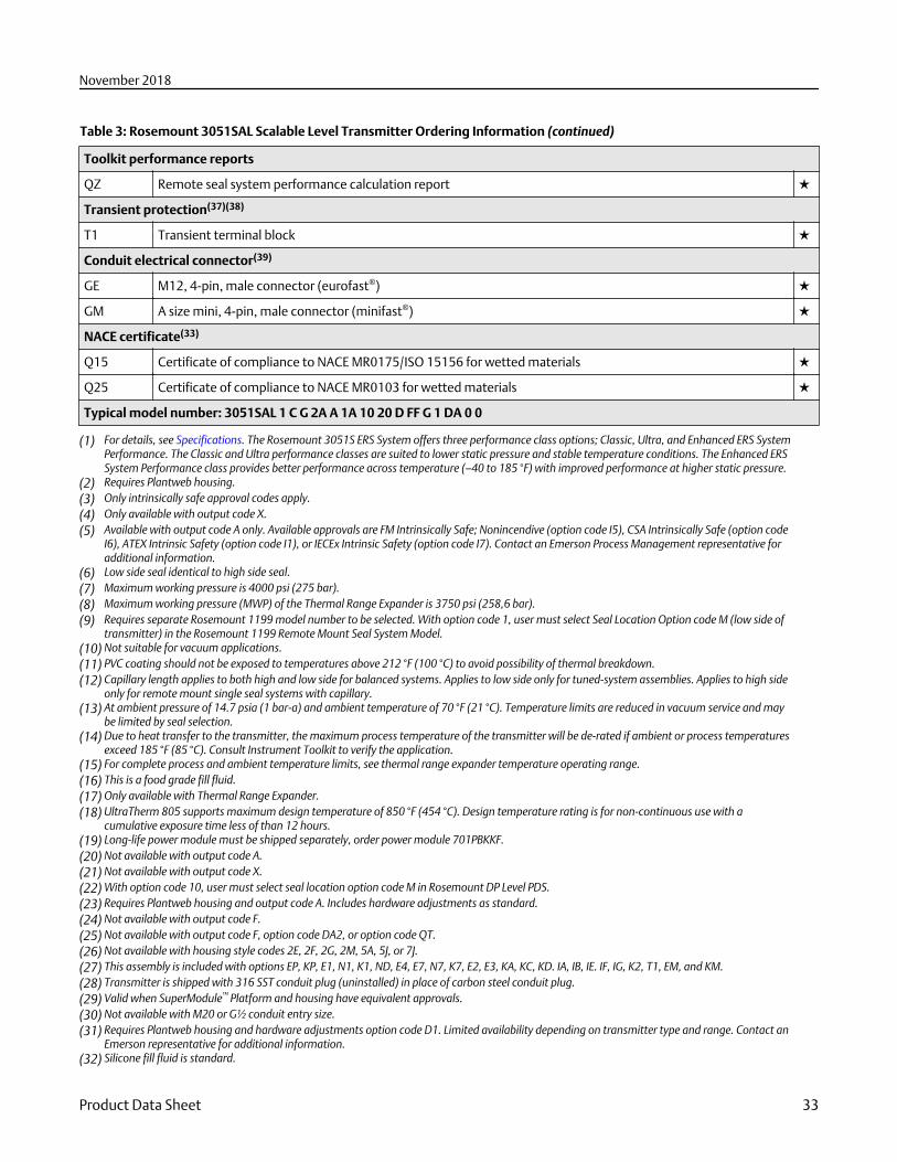
Table 3: Rosemount 3051SAL Scalable Level Transmitter Ordering Information (continued)
Toolkit performance reports
QZ Remote seal system performance calculation report ★
Transient protection(37)(38)
T1 Transient terminal block ★
Conduit electrical connector(39)
GE M12, 4-pin, male connector (eurofast®) ★
GM A size mini, 4-pin, male connector (minifast®) ★
NACE certificate(33)
Q15 Certificate of compliance to NACE MR0175/ISO 15156 for wetted materials ★
Q25 Certificate of compliance to NACE MR0103 for wetted materials ★
Typical model number: 3051SAL 1 C G 2A A 1A 10 20 D FF G 1 DA 0 0
(1) For details, see Specifications. The Rosemount 3051S ERS System offers three performance class options; Classic, Ultra, and Enhanced ERS SystemPerformance. The Classic and Ultra performance classes are suited to lower static pressure and stable temperature conditions. The Enhanced ERSSystem Performance class provides better performance across temperature (–40 to 185 °F) with improved performance at higher static pressure.
(2) Requires Plantweb housing.(3) Only intrinsically safe approval codes apply.(4) Only available with output code X.(5) Available with output code A only. Available approvals are FM Intrinsically Safe; Nonincendive (option code I5), CSA Intrinsically Safe (option code
I6), ATEX Intrinsic Safety (option code I1), or IECEx Intrinsic Safety (option code I7). Contact an Emerson Process Management representative foradditional information.
(6) Low side seal identical to high side seal.(7) Maximum working pressure is 4000 psi (275 bar).(8) Maximum working pressure (MWP) of the Thermal Range Expander is 3750 psi (258,6 bar).(9) Requires separate Rosemount 1199 model number to be selected. With option code 1, user must select Seal Location Option code M (low side of
transmitter) in the Rosemount 1199 Remote Mount Seal System Model.(10) Not suitable for vacuum applications.(11) PVC coating should not be exposed to temperatures above 212 °F (100 °C) to avoid possibility of thermal breakdown.(12) Capillary length applies to both high and low side for balanced systems. Applies to low side only for tuned-system assemblies. Applies to high side
only for remote mount single seal systems with capillary.(13) At ambient pressure of 14.7 psia (1 bar-a) and ambient temperature of 70 °F (21 °C). Temperature limits are reduced in vacuum service and may
be limited by seal selection.(14) Due to heat transfer to the transmitter, the maximum process temperature of the transmitter will be de-rated if ambient or process temperatures
exceed 185 °F (85 °C). Consult Instrument Toolkit to verify the application.(15) For complete process and ambient temperature limits, see thermal range expander temperature operating range.(16) This is a food grade fill fluid.(17) Only available with Thermal Range Expander.(18) UltraTherm 805 supports maximum design temperature of 850 °F (454 °C). Design temperature rating is for non-continuous use with a
cumulative exposure time less of than 12 hours.(19) Long-life power module must be shipped separately, order power module 701PBKKF.(20) Not available with output code A.(21) Not available with output code X.(22) With option code 10, user must select seal location option code M in Rosemount DP Level PDS.(23) Requires Plantweb housing and output code A. Includes hardware adjustments as standard.(24) Not available with output code F.(25) Not available with output code F, option code DA2, or option code QT.(26) Not available with housing style codes 2E, 2F, 2G, 2M, 5A, 5J, or 7J.(27) This assembly is included with options EP, KP, E1, N1, K1, ND, E4, E7, N7, K7, E2, E3, KA, KC, KD. IA, IB, IE. IF, IG, K2, T1, EM, and KM.(28) Transmitter is shipped with 316 SST conduit plug (uninstalled) in place of carbon steel conduit plug.(29) Valid when SuperModule™ Platform and housing have equivalent approvals.(30) Not available with M20 or G½ conduit entry size.(31) Requires Plantweb housing and hardware adjustments option code D1. Limited availability depending on transmitter type and range. Contact an
Emerson representative for additional information.(32) Silicone fill fluid is standard.
November 2018
Product Data Sheet 33
(33) Materials of construction comply with metallurgical requirements highlighted within NACE MR0175/ISO 15156 for sour oil field productionenvironments. Environmental limits apply to certain materials. Consult latest standard for details. Selected materials also conform to NACEMR0103 for sour refining environments. Order with Q15 or Q25 to receive a NACE certificate.
(34) Not available with housing code 01 or 7J.(35) See the Rosemount 3051S Reference Manual for cable requirements. Contact an Emerson representative for additional information.(36) Not available with output code F or X. Not available with housing code 7J.(37) Not available with Housing code 5A, 5J, or 7J.(38) The T1 option is not needed with FISCO Product Certifications; transient protection is included in the FISCO product certification codes IA, IB, IE, IF,
and IG.(39) Not available with Housing code 5A, 5J, or 7J. Available with Intrinsically Safe approvals only. For FM Intrinsically Safe; Nonincendive (option code
I5) or FM FISCO Intrinsically Safe (option code IE), install in accordance with Rosemount drawing 03151-1009.
November 2018
34 Emerson.com/Rosemount
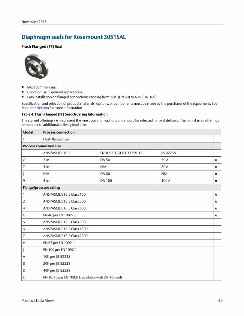
Diaphragm seals for Rosemount 3051SAL
Flush Flanged (FF) Seal
■ Most common seal■ Good for use in general applications■ Easy installation on flanged connections ranging from 2-in. (DN 50) to 4-in. (DN 100)
Specification and selection of product materials, options, or components must be made by the purchaser of the equipment. SeeMaterial selection for more information .
Table 4: Flush Flanged (FF) Seal Ordering Information
The starred offerings (★) represent the most common options and should be selected for best delivery. The non-starred offeringsare subject to additional delivery lead time.
Model Process connection
FF Flush flanged seal
Process connection size
ANSI/ASME B16.5 EN 1092-1/GOST 33259-15 JIS B2238
G 2-in. DN 50 50 A ★
7 3-in. N/A 80 A ★
J N/A DN 80 N/A ★
9 4-in. DN 100 100 A ★
Flange/pressure rating
1 ANSI/ASME B16.5 Class 150 ★
2 ANSI/ASME B16.5 Class 300 ★
4 ANSI/ASME B16.5 Class 600 ★
G PN 40 per EN 1092-1 ★
5 ANSI/ASME B16.5 Class 900
6 ANSI/ASME B16.5 Class 1500
7 ANSI/ASME B16.5 Class 2500
H PN 63 per EN 1092-1
J PN 100 per EN 1092-1
A 10K per JIS B2238
B 20K per JIS B2238
D 40K per JIS B2238
E PN 10/16 per EN 1092-1, available with DN 100 only
November 2018
Product Data Sheet 35
Table 4: Flush Flanged (FF) Seal Ordering Information (continued)
Materials of construction
Isolating diaphragm Upper housing Flange
CA 316L SST 316L SST CS ★
DA 316L SST 316L SST 316 SST ★
CB(1) Alloy C-276 316L SST CS ★
DB(1) Alloy C-276, seam-welded 316L SST 316 SST ★
CC Tantalum 316L SST CS ★
DC Tantalum, seam-welded 316L SST 316 SST ★
C6 Duplex 2205 SST 316 SST CS
D6 Duplex 2205 SST 316 SST 316 SST
Flushing connection ring (lower housing)
0 None ★
A(2) 316 SST ★
B(2) Alloy C-276 ★
Flushing connection quantity and size
0 None ★
1 One ¼–18 NPT flushing connection ★
3 Two ¼–18 NPT flushing connections ★
7 One ½–14 NPT flushing connection ★
9 Two ½–14 NPT flushing connections ★
Options (include with selected model number)
Cold temperature remote seal applications
RB Extra fill fluid for cold temperature applications
Remote seal diaphragm thickness(3)
SC 0.006-in. (150 µm) available with 316L SST and Alloy C-276
Flushing connection ring plugs
SF Alloy C-276 plug(s) for flushing connection(s) ★
SG SST plug(s) for flushing connection(s) ★
SH SST drain/vent(s) for flushing connection(s) ★
Lower housing alignment clamp
SA Lower housing alignment clamp ★
Intermediate gasket material
S0 No gasket for flushing ring connection (lower housing) ★
SY Thermo-tork® TN-9000 ★
SJ PTFE gasket ★
SK Barium Sulfate-filled PTFE gasket
November 2018
36 Emerson.com/Rosemount
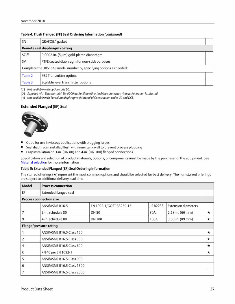
Table 4: Flush Flanged (FF) Seal Ordering Information (continued)
SN GRAFOIL® gasket
Remote seal diaphragm coating
SZ(3) 0.0002-in. (5 µm) gold-plated diaphragm
SV PTFE coated diaphragm for non-stick purposes
Complete the 3051SAL model number by specifying options as needed:
Table 2 ERS Transmitter options
Table 3 Scalable level transmitter options
(1) Not available with option code SC.(2) Supplied with Thermo-tork® TN-9000 gasket if no other flushing connection ring gasket option is selected.(3) Not available with Tantalum diaphragms (Material of Construction codes CC and DC).
Extended Flanged (EF) Seal
■ Good for use in viscous applications with plugging issues■ Seal diaphragm installed flush with inner tank wall to prevent process plugging■ Easy installation on 3-in. (DN 80) and 4-in. (DN 100) flanged connections
Specification and selection of product materials, options, or components must be made by the purchaser of the equipment. SeeMaterial selection for more information .
Table 5: Extended Flanged (EF) Seal Ordering Information
The starred offerings (★) represent the most common options and should be selected for best delivery. The non-starred offeringsare subject to additional delivery lead time.
Model Process connection
EF Extended flanged seal
Process connection size
ANSI/ASME B16.5 EN 1092-1/GOST 33259-15 JIS B2238 Extension diameters
7 3-in. schedule 80 DN 80 80A 2.58-in. (66 mm) ★
9 4-in. schedule 80 DN 100 100A 3.50-in. (89 mm) ★
Flange/pressure rating
1 ANSI/ASME B16.5 Class 150 ★
2 ANSI/ASME B16.5 Class 300 ★
4 ANSI/ASME B16.5 Class 600 ★
G PN 40 per EN 1092-1 ★
5 ANSI/ASME B16.5 Class 900
6 ANSI/ASME B16.5 Class 1500
7 ANSI/ASME B16.5 Class 2500
November 2018
Product Data Sheet 37
Table 5: Extended Flanged (EF) Seal Ordering Information (continued)
H PN 63 per EN 1092-1
J PN 100 per EN 1092-1
A 10K per JIS B2238
B 20K per JIS B2238
D 40K per JIS B2238
E PN 10/16 per EN 1092-1, available with DN 100 only
Materials of construction
Isolating diaphragm Extension/gasket surface Mounting flange
CA 316L SST 316L SST CS ★
DA 316L SST 316L SST 316 SST ★
CB Alloy C-276 Alloy C-276 CS ★
DB Alloy C-276 Alloy C-276 316 SST ★
C6 Duplex 2205 SST Duplex 2205 SST CS
D6 Duplex 2205 SST Duplex 2205 SST 316 SST
Seal extension length
20 2-in. (50 mm) ★
40 4-in. (100 mm) ★
60 6-in. (150 mm) ★
Options (include with selected model number)
Cold temperature remote seal applications
RB Extra fill fluid for cold temperature applications ★
Remote seal diaphragm thickness
SC 0.006-in. (150 µm) diaphragm thickness
Remote seal diaphragm coating
SZ 0.0002-in. (5 µm) gold-plated diaphragm
SV PTFE coated diaphragm for non-stick purposes
Complete the 3051SAL model number by specifying options as needed:
Table 2 ERS Transmitter options
Table 3 Scalable level transmitter options
Remote Flanged (RF) Seal
■ Designed to improve performance on smaller process connections■ Easy installation on flanged connections ranging from ½- to 1½-in. (DN 25– DN 40)■ Lower housing/flushing ring required
November 2018
38 Emerson.com/Rosemount
Specification and selection of product materials, options, or components must be made by the purchaser of the equipment. SeeMaterial selection for more information .
Table 6: Remote Flanged (RF) Seal Ordering Information
The starred offerings (★) represent the most common options and should be selected for best delivery. The non-starred offeringsare subject to additional delivery lead time.
Model Process connection
RF Remote flanged seal
Process connection size
ANSI/ASME B16.5 EN 1092-1/GOST 33259-15 JIS B2238
2 1-in. N/A 25A ★
4 1½-in. N/A 40A ★
D N/A DN 25 N/A ★
F N/A DN 40 N/A ★
1 ½-in. N/A N/A
A ¾-in. N/A N/A
Flange/pressure rating
1 ANSI/ASME B16.5 Class 150 ★
2 ANSI/ASME B16.5 Class 300 ★
4 ANSI/ASME B16.5 Class 600 ★
G PN 40 per EN 1092-1 ★
5 ANSI/ASME B16.5 Class 900
6 ANSI/ASME B16.5 Class 1500
7 ANSI/ASME B16.5 Class 2500
A 10K per JIS B2238
B 20K per JIS B2238
D 40K per JIS B2238
Materials of construction
Isolating diaphragm Upper housing Flange
CA 316L SST 316L SST CS ★
DA 316L SST 316L SST 316 SST ★
CB Alloy C-276 316L SST CS ★
DB Alloy C-276 316L SST 316 SST ★
CC Tantalum 316L SST CS ★
DC Tantalum 316L SST 316 SST ★
C6 Duplex 2205 SST 316 SST CS
D6 Duplex 2205 SST 316 SST 316 SST
Flushing connection ring material (lower housing)(1)
A 316L SST ★
November 2018
Product Data Sheet 39
Table 6: Remote Flanged (RF) Seal Ordering Information (continued)
B Alloy C-276 ★
Flushing connection quantity and size
5 None ★
1 One ¼–18 NPT flushing connection ★
3 Two ¼–18 NPT flushing connections ★
7 One ½–14 NPT flushing connection
9 Two ½–14 NPT flushing connections
Options (include with selected model number)
Cold temperature remote seal application
RB Extra fill fluid for cold temperature applications ★
Remote seal diaphragm thickness
SC(2) 0.006-in. (150 µm) diaphragm thickness
Large diaphragm size
S9 4.1-in. (104 mm) diaphragm diameter
Flushing connection ring plugs
SF Alloy C-276 plug(s) for flushing connection(s) ★
SG 316 SST plug(s) for flushing connection(s) ★
SH 316 SST drain/vent(s) for flushing connection(s) ★
Flushing ring connection gaskets
SY C-4401 gasket ★
SJ PTFE gasket ★
SR Ethylene Propylene gasket
SN GRAFOIL gasket
S6 TopChem 2000
SK Barium Sulfate-filled PTFE gasket
Remote seal bolt material
S3 304 SST bolts ★
S4 316 SST bolts
Remote seal diaphragm coating
SZ(2) 0.0002-in. (5 µm) gold-plated diaphragm
SV PTFE coated diaphragm for non-stick purposes
Complete the 3051SAL model number by specifying options as needed:
Table 2 ERS Transmitter options
Table 3 Scalable level transmitter options
(1) Supplied with C-4401 Aramid fiber gasket if no other remote seal gasket material is selected.(2) Not available with Tantalum diaphragms (Material of Construction codes CC and DC).
November 2018
40 Emerson.com/Rosemount
PF Pancake Seal
■ Remote mount connection with capillary on the side of the seal■ Support tube used to facilitate installation■ Can be ordered with or without flange
Table 7: PF Pancake Seal Ordering Information
The starred offerings (★) represent the most common options and should be selected for best delivery. The non-starred offeringsare subject to additional delivery lead time.
Model Process connection
PF Pancake seal ★
Process connection size
ANSI EN 1092-1/GOST 33259-15
G 2-in. DN 50 ★
7 3-in. N/A ★
J N/A DN 80 ★
Flange/pressure rating
ANSI EN 1092-1/GOST 33259-15
0 No flanged supplied, seal maximum workingpressure (MWP) based on customer supplied flange
N/A ★
9 N/A No flanged supplied, seal MWP based on customersupplied flange
★
1 Class 150 N/A ★
2 Class 300 N/A ★
4 Class 600 N/A ★
G N/A PN40 ★
5 Class 900 N/A
6 Class 1500 N/A
7 Class 2500 N/A
H N/A PN63
J N/A PN100
Diaphragm and wetted, upper housing, flange material
Diaphragm and wetted Upper housing Flange
LA(1) 316L SST 316L SST None ★
CA(1) 316L SST 316L SST CS ★
DA(1) 316L SST 316L SST 316 SST ★
LB Alloy C-276, seam welded 316L SST None ★
CB Alloy C-276, seam welded 316L SST CS ★
November 2018
Product Data Sheet 41
Table 7: PF Pancake Seal Ordering Information (continued)
DB Alloy C-276, seam welded 316L SST 316 SST ★
LC Tantalum, seam welded 316L SST None ★
CC Tantalum, seam welded 316L SST CS ★
DC Tantalum, seam welded 316L SST 316 SST ★
L6 Duplex 2205 SST 316 SST None
C6 Duplex 2205 SST 316 SST CS
D6 Duplex 2205 SST 316 SST 316 SST
Flushing connection ring (lower housing)
0 None ★
A(2) 316 SST ★
B(2) Alloy C-276 ★
Flushing connection quantity and size
0 None ★
1 One ¼–18 NPT flushing connection ★
3 Two ¼–18 NPT flushing connections ★
7 One ½–14 NPT flushing connection ★
9 Two ½–14 NPT flushing connections ★
Options (include with selected model number)
Lower housing alignment clamp
SA Lower housing alignment clamp ★
Flushing connection ring gaskets(2)
S0 No gasket for lower housing ★
SY Thermo-tork TN-9000 ★
SJ PTFE gasket ★
SK Barium Sulfate-filled PTFE gasket
SN GRAFOIL gasket
Flushing connection ring plugs
SF Alloy C-276 plug(s) for flushing connection(s) ★
SG SST plug(s) for flushing connection(s) ★
SH SST drain/vent(s) for flushing connection(s) ★
Remote seal diaphragm thickness(3)
SC 0.006-in. (150 µm) diaphragm thickness
Cold temperature remote seal applications
RB Extra fill fluid for cold temperature applications
Remote seal diaphragm coating
SZ(3) 0.0002-in. (5 µm) gold-plated diaphragm
November 2018
42 Emerson.com/Rosemount
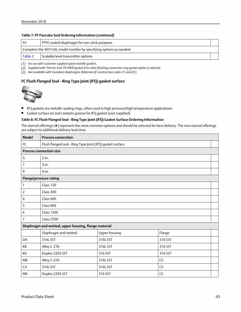
Table 7: PF Pancake Seal Ordering Information (continued)
SV PTFE coated diaphragm for non-stick purposes
Complete the 3051SAL model number by specifying options as needed:
Table 3 Scalable level transmitter options
(1) For use with customer supplied spiral metallic gaskets.(2) Supplied with Thermo-tork TN-9000 gasket if no other flushing connection ring gasket option is selected.(3) Not available with Tantalum diaphragms (Material of Construction codes CC and DC).
FC Flush Flanged Seal - Ring Type Joint (RTJ) gasket surface
■ RTJ gaskets are metallic sealing rings, often used in high pressure/high temperature applications■ Gasket surface on seal contains groove for RTJ gasket (user supplied)
Table 8: FC Flush Flanged Seal - Ring Type Joint (RTJ) Gasket Surface Ordering Information
The starred offerings (★) represent the most common options and should be selected for best delivery. The non-starred offeringsare subject to additional delivery lead time.
Model Process connection
FC Flush flanged seal - Ring Type Joint (RTJ) gasket surface
Process connection size
G 2-in.
7 3-in.
9 4-in.
Flange/pressure rating
1 Class 150
2 Class 300
4 Class 600
5 Class 900
6 Class 1500
7 Class 2500
Diaphragm and wetted, upper housing, flange material
Diaphragm and wetted Upper housing Flange
DA 316L SST 316L SST 316 SST
KB Alloy C-276 316L SST 316 SST
K6 Duplex 2205 SST 316 SST 316 SST
MB Alloy C-276 316L SST CS
CA 316L SST 316L SST CS
M6 Duplex 2205 SST 316 SST CS
November 2018
Product Data Sheet 43
Table 8: FC Flush Flanged Seal - Ring Type Joint (RTJ) Gasket Surface Ordering Information (continued)
Flushing connection ring material (lower housing)
0 None
A 316 SST
B Alloy C-276
Flushing connection quantity and size
0 None
1 One ¼–18 NPT flushing connection
3 Two ¼–18 NPT flushing connection
7 One ½–14 NPT flushing connection
9 Two ½–14 NPT flushing connection
Options (include with selected model number)
Flushing ring connection plugs
SF Alloy C-276 plug(s) for flushing connection(s)
SG 316 SST plug(s) for flushing connection(s)
SH 316 SST vent/drain for flushing connection(s)
Remote seal diaphragm thickness
SC 0.006-in. (150 µm) available with 316L SST, Alloy C-276, and duplex 2205 SST for abrasive applications
Cold temperature remote seal application
RB Extra fill for cold temp application
Remote seal diaphragm coating(1)
SZ 0.002-in. (5 µm) gold-plated diaphragm
SV PTFE coated diaphragm for nonstick purposes only
Complete the 3051SAL model number by specifying options as needed:
Table 2 ERS Transmitter options
Table 3 Scalable level transmitter options
(1) Only available on 316LSST and Alloy C-276.
RC Remote Flanged Seal - Ring Type Joint (RTJ) gasket surface
■ Remote mounted with capillary■ RTJ gaskets are metallic sealing rings, often used in high pressure/high temperature applications■ Gasket surface on seal contains groove for RTJ gasket (user supplied)
November 2018
44 Emerson.com/Rosemount
Table 9: RC Remote Flanged Seal - Ring Type Joint (RTJ) Gasket Surface Ordering Information
The starred offerings (★) represent the most common options and should be selected for best delivery. The non-starred offeringsare subject to additional delivery lead time.
Model Process connection
RC Remote flanged seal - Ring Type Joint (RTJ) gasket surface
Process connection sizes
1 ½-in. (Class 150 to 1500 includes mounting ring bolts and mounting studs)
A ¾-in. (Class 150 includes mounting ring bolts and mounting studs)
2 1-in.
4 1½-in.
Flange/pressure rating
1 Class 150
2 Class 300
4 Class 600
5 Class 900
6 Class 1500
7 Class 2500
Diaphragm and wetted, upper housing
Diaphragm and wetted Upper housing
LA 316L SST 316L SST
LB Alloy C-276 316L SST
LC Tantalum 316L SST
Flushing connection ring material (lower housing)(1)
A 316L SST
B Alloy C-276
Flushing ring connection and size
0 None
1 One ¼–18 NPT flushing connections
3 Two ¼–18 NPT flushing connection
7 One ½–14 NPT flushing connection
9 Two ½–14 NPT flushing connection
Options (include with selected model number)
Flushing connection ring gaskets
SY C-4401 gasket ★
SJ PTFE gasket ★
SR Ethylene Propylene gasket
SN GRAFOIL gasket
November 2018
Product Data Sheet 45
Table 9: RC Remote Flanged Seal - Ring Type Joint (RTJ) Gasket Surface Ordering Information (continued)
S6 TopChem 2000
SK Barium Sulfate-filled PTFE gasket
Flushing connection ring plugs
SF Alloy C-276 plug(s) for flushing connection(s)
SG 316 SST plug(s) for flushing connection(s)
SH 316 SST vent/drain for flushing connection(s)
Remote seal diaphragm thickness
SC 0.006-in. (150 µm) available with 316L SST, Alloy C-276, and duplex 2205 SST for abrasive applications
Remote seal bolt material
S3(2) 304 SST bolts (only available for stud bolt design)
S4 316 SST bolts (only available for stud bolt design) ★
Large diaphragm size
S9 4.1 in. (104 mm) diaphragm diameter
Cold temperature remote seal application
RB Extra fill for cold temp application
Remote seal diaphragm coating(3)
SZ 0.002-in. (5 µm) gold-plated diaphragm
SV PTFE coated diaphragm for nonstick purposes only
Complete the 3051SAL model number by specifying options as needed:
Table 2 ERS Transmitter options
Table 3 Scalable level transmitter options
(1) Supplied with C-4401 aramid fiber gasket if no other remote seal gasket material is selected.(2) Standard stud bolts are carbon steel.(3) Only available on 316LSST and Alloy C-276.
Remote Threaded (RT) Seal
■ For use with threaded process connections (¼-18 to 1-11.5 NPT)■ Rated for use in high-pressure applications (up to 2500 PSI)■ Optional flushing connections available
Table 10: RT Threaded Seal Ordering Information
The starred offerings (★) represent the most common options and should be selected for best delivery. The non-starred offeringsare subject to additional delivery lead time.
Model Process connection
RT Remote threaded seal ★
November 2018
46 Emerson.com/Rosemount

Table 10: RT Threaded Seal Ordering Information (continued)
Process connection size
3 ½-14 NPT ★
4 ¾-14 NPT ★
5 1-11.5 NPT ★
1 ¼-18 NPT
6 1¼ - 11.5 NPT
Pressure rating
0 2500 psi ★
8(1) 1500 psi ★
Isolating diaphragm material Upper housing material Flange
CA 316L SST 316L SST CS ★
DA 316L SST 316L SST 316 SST ★
CB Alloy C-276 316L SST CS ★
DB Alloy C-276 316L SST 316 SST ★
CC Tantalum 316L SST CS ★
DC Tantalum 316L SST 316 SST ★
Flushing connection ring material (lower housing)(2)(3)
A 316L SST ★
B Alloy C-276 ★
Flushing ring connection quantity and size
1 One ¼-in. flushing connection ★
3 Two ¼-in. flushing connections ★
5 None ★
7 One ½-14 NPT flushing connection ★
9 Two ½-14 NPT flushing connection ★
Options (include with selected model number)
Cold temperature remote seal application
RB Extra fill fluid for cold temperature applications ★
Remote seal diaphragm thickness
SC(4) 0.006-in. (150 µm) diaphragm thickness
Remote seal flushing plug, drain/vent
SF Alloy C-276 plug(s) for flushing connection(s) ★
SG 316 SST plug(s) for flushing connection(s) ★
SH 316 SST drain/vent(s) for flushing connection(s) ★
Remote seal gasket material
SY C-4401 gasket (for use with flushing connection ring) ★
November 2018
Product Data Sheet 47
Table 10: RT Threaded Seal Ordering Information (continued)
SJ PTFE gasket (for use with flushing connection ring) ★
SR Ethylene Propylene gasket (for use with flushing connection ring) ★
SN GRAFOIL gasket (for use with flushing connection ring) ★
S6 TopChem 2000 (for use with flushing connection ring)
SK Barium Sulfate-filled PTFE gasket (for use with flushing connection ring)
Remote seal bolt
S3 304 SST bolts ★
S4 316 SST bolts
Large diaphragm size
S9(5) 4.1-in. (104 mm) diaphragm diameter
Remote seal diaphragm coating
SZ(4) 0.0002-in. (5 µm) gold-plated diaphragm
SV PTFE coated diaphragm for non-stick purposes
Special threads in lower housing
R9 Male lower housing threads
Complete the 3051SAL model number by specifying options as needed:
Table 2 ERS transmitter options
Table 3 Scalable level transmitter options
(1) Only available with 4.1 in. (104 mm) diaphragm (large diaphragm side code S9).(2) Supplied with C4401 aramid fiber gasket if no other remote seal gasket material is selected.(3) Flushing connection ring/lower housing assembly bolts provided as standard are carbon steel.(4) Not available with Tantalum diaphragms (Material of Construction codes CC and DC).(5) Only available with Pressure Rating code 8.
SC Hygienic Tri-Clamp® Seal
■ Good for use in hygienic applications■ Easy installation on Tri-Clover style Tri-Clamp connections (1.5-in. to 3-in.)■ Conforms to 3-A® standard 74-03
Table 11: SC Hygienic Tri-Clover Style Tri-Clamp Seal Ordering Information
The starred offerings (★) represent the most common options and should be selected for best delivery. The non-starred offeringsare subject to additional delivery lead time.
Process connection
SC(1)(2) Tri-Clover style Tri-Clamp seal ★
Process connection size
3 (3) 1½-in. ★
5(4) 2-in. ★
November 2018
48 Emerson.com/Rosemount
Table 11: SC Hygienic Tri-Clover Style Tri-Clamp Seal Ordering Information (continued)
7 3-in. ★
Maximum working pressure
0 1000 PSI ★
Isolating diaphragm material Upper housing material
LA00 316L SST 316L SST ★
LB00 Alloy C-276 316L SST
Options (include with selected model number)
Remote seal diaphragm polishing
RE Electropolishing
Remote seal diaphragm surface finish
RD 10 µin. (0.25 µm) Ra diaphragm surface finish
RG 15 µin. (0.375 µm) Ra diaphragm surface finish
RH 20 µin. (0.5 µm) Ra diaphragm surface finish
Surface finish certification(5)
Q16 Surface finish certification for hygienic remote seals ★
Complete the Rosemount 3051SAL model number by specifying options as needed:
Table 2 ERS Transmitter options
Table 3 Scalable level transmitter options
(1) Clamp and gasket furnished by user. The maximum working pressure is dependent upon the clamp pressure rating.(2) All process wetted parts have surface finish of Ra < 32 μin (0.81 μm) standard unless otherwise specified.(3) Min span is 1000 inH2O or 2490 mbar for 1½-in. Tri- Clamp seal.(4) Min span is 150 inH2O or 373 mbar for 2-in. Tri-Clamp seal.(5) Q16 is only available when the diaphragm seal has surface finish options (RD, RG, and RH).
SS Hygienic Tank Spud Seal
■ Commonly used in hygienic level applications■ Seal diaphragm installed flush with inner tank wall■ Conforms to 3-A standard 74-03
Table 12: SS Hygienic Tank Spud Seal Ordering Information
The starred offerings (★) represent the most common options and should be selected for best delivery. The non-starred offeringsare subject to additional delivery lead time.
Process connection
SS(1)(2) Hygienic Tank Spud Seal ★
Process connection size
A 4-in. Sch. 5 Tri-Clamp ★
November 2018
Product Data Sheet 49
Table 12: SS Hygienic Tank Spud Seal Ordering Information (continued)
Maximum working pressure (clamp rating)
0 150 psi (10,3 bar) ★
Upper housing
A 316L SST ★
Diaphragm and wetted, extension material
Diaphragm and wetted Extension
AL(3) 316L SST 316L SST ★
BB Alloy C-276 316L SST
Extension length
2 2-in. (50 mm) extension ★
6 6-in. (150 mm) extension ★
Options (include with selected model number)
Remote seal diaphragm thickness
SC 0.006-in. (150 µm) diaphragm thickness
Tank spud included with shipment
S1 Tank spud included with shipment ★
Remote seal diaphragm polishing
RE Electropolishing
Remote seal diaphragm surface finish
RH 20 µin. (0.5 µm) Ra diaphragm surface finish
RG(4) 15 µin. (0.375 µm) Ra diaphragm surface finish
Surface finish certification(5)
Q16 Surface finishing certification for hygienic remote seals ★
Complete the 3051SAL model number by specifying options as needed:
Table 2 ERS Transmitter options
Table 3 Scalable level transmitter options
(1) Clamp and Ethylene Propylene O-ring (conforms to 3-A standard 74 and USP Class VI) supplied.(2) All process wetted parts have surface finish of Ra < 32 μin (0.81 μm) standard unless otherwise specified.(3) Diaphragm brazed and TIG-welded to extension.(4) Requires option code RE (Electropolishing).(5) Q16 is only available when the diaphragm seal has surface finish options (RG and RH).
November 2018
50 Emerson.com/Rosemount
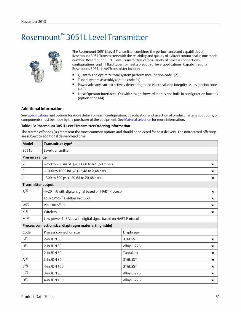
Rosemount™ 3051L Level Transmitter
The Rosemount 3051L Level Transmitter combines the performance and capabilities ofRosemount 3051 Transmitters with the reliability and quality of a direct mount seal in one modelnumber. Rosemount 3051L Level Transmitters offer a variety of process connections,configurations, and fill fluid types to meet a breadth of level applications. Capabilities of aRosemount 3051L Level Transmitter include:
■ Quantify and optimize total system performance (option code QZ)■ Tuned-system assembly (option code S1)■ Power advisory can pro actively detect degraded electrical loop integrity issues (option code
DA0)■ Local Operator Interface (LOI) with straightforward menus and built-in configuration buttons
(option code M4)
Additional information:
See Specifications and options for more details on each configuration. Specification and selection of product materials, options, orcomponents must be made by the purchaser of the equipment. See Material selection for more information.
Table 13: Rosemount 3051L Level Transmitter Ordering Information
The starred offerings (★) represent the most common options and should be selected for best delivery. The non-starred offeringsare subject to additional delivery lead time.
Model Transmitter type(1)
3051L Level transmitter
Pressure range
2 –250 to 250 inH2O (–621,60 to 621,60 mbar) ★
3 –1000 to 1000 inH2O (–2,48 to 2,48 bar) ★
4 –300 to 300 psi (–20,68 to 20,68 bar) ★
Transmitter output
A(2) 4–20 mA with digital signal based on HART Protocol ★
F FOUNDATION™ Fieldbus Protocol ★
W(3) PROFIBUS® PA ★
X(4) Wireless ★
M(5) Low-power 1–5 Vdc with digital signal based on HART Protocol
Process connection size, diaphragm material (high side)
Code Process connection size Diaphragm
G(6) 2-in./DN 50 316L SST ★
H(6) 2-in./DN 50 Alloy C-276 ★
J 2-in./DN 50 Tantalum ★
A(6) 3-in./DN 80 316L SST ★
B(6) 4-in./DN 100 316L SST ★
C(6) 3-in./DN 80 Alloy C-276 ★
D(6) 4-in./DN 100 Alloy C-276 ★
November 2018
Product Data Sheet 51
Table 13: Rosemount 3051L Level Transmitter Ordering Information (continued)
E 3-in./DN 80 Tantalum ★
F 4-in./DN 100 Tantalum ★
Seal extension length (high side)
0 None, flush mount ★
2 2-in./50 mm ★
4 4-in./100 mm ★
6 6-in./150 mm ★
Mounting flange size, rating, material (high side)
Size Rating Material
M 2-in. ANSI/ASME B16.5 Class 150 CS ★
A 3-in. ANSI/ASME B16.5 Class 150 CS ★
B 4-in. ANSI/ASME B16.5 Class 150 CS ★
N 2-in. ANSI/ASME B16.5 Class 300 CS ★
C 3-in. ANSI/ASME B16.5 Class 300 CS ★
D 4-in. ANSI/ASME B16.5 Class 300 CS ★
P 2-in. ANSI/ASME B16.5 Class 600 CS ★
E 3-in. ANSI/ASME B16.5 Class 600 CS ★
X(6) 2-in. ANSI/ASME B16.5 Class 150 316 SST ★
F(6) 3-in. ANSI/ASME B16.5 Class 150 316 SST ★
G(6) 4-in. ANSI/ASME B16.5 Class 150 316 SST ★
Y(6) 2-in. ANSI/ASME B16.5 Class 300 316 SST ★
H(6) 3-in. ANSI/ASME B16.5 Class 300 316 SST ★
J(6) 4-in. ANSI/ASME B16.5 Class 300 316 SST ★
Z(6) 2-in. ANSI/ASME B16.5 Class 600 316 SST ★
L(6) 3-in. ANSI/ASME B16.5 Class 600 316 SST ★
Q DN 50 PN 10–40 per EN 1092-1 CS ★
R DN 80 PN 40 per EN 1092-1 CS ★
S DN 100 PN 40 per EN 1092-1 CS ★
V DN 100 PN 10/16 per EN 1092-1 CS ★
K(6) DN 50 PN 10–40 per EN 1092-1 316 SST ★
T(6) DN 80 PN 40 per EN 1092-1 316 SST ★
U(6) DN 100 PN 40 per EN 1092-1 316 SST ★
W(6) DN 100 PN 10/16 per EN 1092-1 316 SST ★
7(6) 4-in. ANSI/ASME B16.5 Class 600 316 SST ★
1 N/A 10K per JIS B2238 CS
2 N/A 20K per JIS B2238 CS
November 2018
52 Emerson.com/Rosemount
Table 13: Rosemount 3051L Level Transmitter Ordering Information (continued)
3 N/A 40K per JIS B2238 CS
4(6) N/A 10K per JIS B2238 316 SST
5(6) N/A 20K per JIS B2238 316 SST
6(6) N/A 40K per JIS B2238 316 SST
Seal fill fluid (high side) Specific gravity Temperature limits(7)(8)
D Silicone 200 0.934 –49 to 401 °F (–45 to 205 °C) ★
F Silicone 200 forvacuumapplications
0.934 For use in vacuum applications below 14.7 psia (1 bar-a), refer tovapor pressure curves in Rosemount DP Level Fill FluidSpecification Technical Note.
★
J(9) Tri-Therm 300 0.795 –40 to 401 °F(–40 to 205 °C) ★
Q(9) Tri-Therm 300 forvacuumapplications
0.795
For use in vacuum applications below 14.7 psia (1 bar-a), refer tovapor pressure curves in Rosemount DP Level Fill FluidSpecification Technical Note.
★
L Silicone 704 1.07 32 to 401 °F (0 to 205 °C) ★
C Silicone 704 forvacuumapplications
1.07 For use in vacuum applications below 14.7 psia (1 bar-a), refer tovapor pressure curves in Rosemount DP Level Fill FluidSpecification Technical Note.
★
A SYLTHERM XLT 0.85 –157 to 293 °F (–105 to 145 °C) ★
H Inert (halocarbon) 1.85 –49 to 320 °F (–45 to 160 °C) ★
G(9)(10) Glycerin and water 1.13 5 to 203 °F (–15 to 95 °C) ★
N(9) Neobee M-20 0.94 5 to 401 °F (–15 to 205 °C) ★
P(9)(10) Propylene glycoland water
1.02 5 to 203 °F (–15 to 95 °C) ★
Low pressure side
Configuration Flange adapter Diaphragm material Sensor fill fluid
11(6) Gage SST 316L SST Silicone ★
21 Differential SST 316L SST Silicone ★
22 Differential SST Alloy C-276 (SST valve seat) Silicone ★
27(6) Differential SST Alloy C (Alloy C-276 valve seat) Silicone ★
2A(11) Differential SST 316L SST Inert (halocarbon) ★
2B(11) Differential SST Alloy C-276 (SST valve seat) Inert (halocarbon) ★
31(6) Tuned-systemassembly withremote seal
None 316L SST Silicone (requires option codeS1)
★
O-ring
A Glass-filled PTFE ★
Housing material Conduit entry size
A Aluminum ½–14 NPT ★
B Aluminum M20 ×1.5 ★
November 2018
Product Data Sheet 53
Table 13: Rosemount 3051L Level Transmitter Ordering Information (continued)
J SST ½–14 NPT ★
K SST M20 × 1.5 ★
P(12) Engineered polymer No conduit entries ★
D(13) Aluminum G½
M(13) SST G½
Wireless options (requires wireless output code X and engineered polymer housing code P)
Wireless transmit rate, operating frequency, and protocol
WA3 User configurable transmit rate, 2.4 GHz WirelessHART® Protocol ★
Antenna and SmartPower
WP5 Internal antenna, compatible with Green Power module (I.S. Power Module sold separately) ★
HART Revision configuration(2) (requires HART output code A)
HR5 Configured for HART Revision 5 ★
HR7 Configured for HART Revision 7 ★
Options (include with selected model number)
Extended product warranty
WR3 3-year limited warranty ★
WR5 5-year limited warranty ★
Plantweb control functionality
A01(14) FOUNDATION Fieldbus Control Function Block Suite ★
DA0(15) Power Advisory HART Diagnostic ★
D01(14) FOUNDATION Fieldbus Diagnostics Suite ★
Seal assemblies(16)
S1 Assembled to one Rosemount 1199 Seal ★
Product certifications
E8 ATEX Flameproof and Dust Certification ★
I1(17) ATEX Intrinsic Safety and Dust ★
IA ATEX FISCO Intrinsic Safety; for FOUNDATION Fieldbus or PROFIBUS PA protocols only ★
N1 ATEX Type n Certification and Dust ★
K8 ATEX Flameproof, Intrinsic Safety, Type n, Dust (combination of E8, I1, and N1) ★
E4(18) TIIS Flameproof ★
E5 FM Explosion-proof, Dust Ignition-proof ★
I5(19) FM Intrinsically Safe, Nonincendive ★
IE FM FISCO Intrinsically Safe; for FOUNDATION Fieldbus or PROFIBUS PA protocols only ★
K5 FM Explosion-proof, Dust Ignition-Proof, Intrinsically Safe, and Division 2 ★
C6 CSA Explosion-proof, Dust Ignition-proof, Intrinsically Safe, and Division 2 ★
November 2018
54 Emerson.com/Rosemount
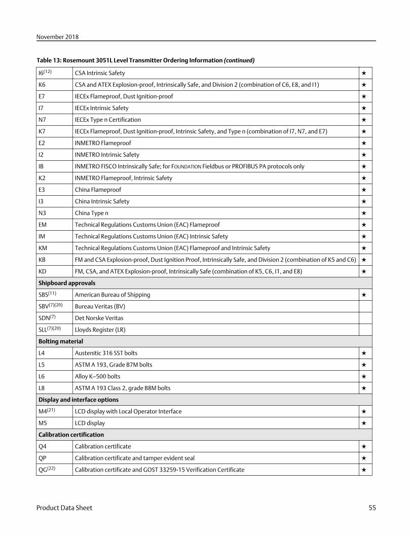
Table 13: Rosemount 3051L Level Transmitter Ordering Information (continued)
I6(12) CSA Intrinsic Safety ★
K6 CSA and ATEX Explosion-proof, Intrinsically Safe, and Division 2 (combination of C6, E8, and I1) ★
E7 IECEx Flameproof, Dust Ignition-proof ★
I7 IECEx Intrinsic Safety ★
N7 IECEx Type n Certification ★
K7 IECEx Flameproof, Dust Ignition-proof, Intrinsic Safety, and Type n (combination of I7, N7, and E7) ★
E2 INMETRO Flameproof ★
I2 INMETRO Intrinsic Safety ★
IB INMETRO FISCO Intrinsically Safe; for FOUNDATION Fieldbus or PROFIBUS PA protocols only ★
K2 INMETRO Flameproof, Intrinsic Safety ★
E3 China Flameproof ★
I3 China Intrinsic Safety ★
N3 China Type n ★
EM Technical Regulations Customs Union (EAC) Flameproof ★
IM Technical Regulations Customs Union (EAC) Intrinsic Safety ★
KM Technical Regulations Customs Union (EAC) Flameproof and Intrinsic Safety ★
KB FM and CSA Explosion-proof, Dust Ignition Proof, Intrinsically Safe, and Division 2 (combination of K5 and C6) ★
KD FM, CSA, and ATEX Explosion-proof, Intrinsically Safe (combination of K5, C6, I1, and E8) ★
Shipboard approvals
SBS(11) American Bureau of Shipping ★
SBV(7)(20) Bureau Veritas (BV)
SDN(7) Det Norske Veritas
SLL(7)(20) Lloyds Register (LR)
Bolting material
L4 Austenitic 316 SST bolts ★
L5 ASTM A 193, Grade B7M bolts ★
L6 Alloy K–500 bolts ★
L8 ASTM A 193 Class 2, grade B8M bolts ★
Display and interface options
M4(21) LCD display with Local Operator Interface ★
M5 LCD display ★
Calibration certification
Q4 Calibration certificate ★
QP Calibration certificate and tamper evident seal ★
QG(22) Calibration certificate and GOST 33259-15 Verification Certificate ★
November 2018
Product Data Sheet 55
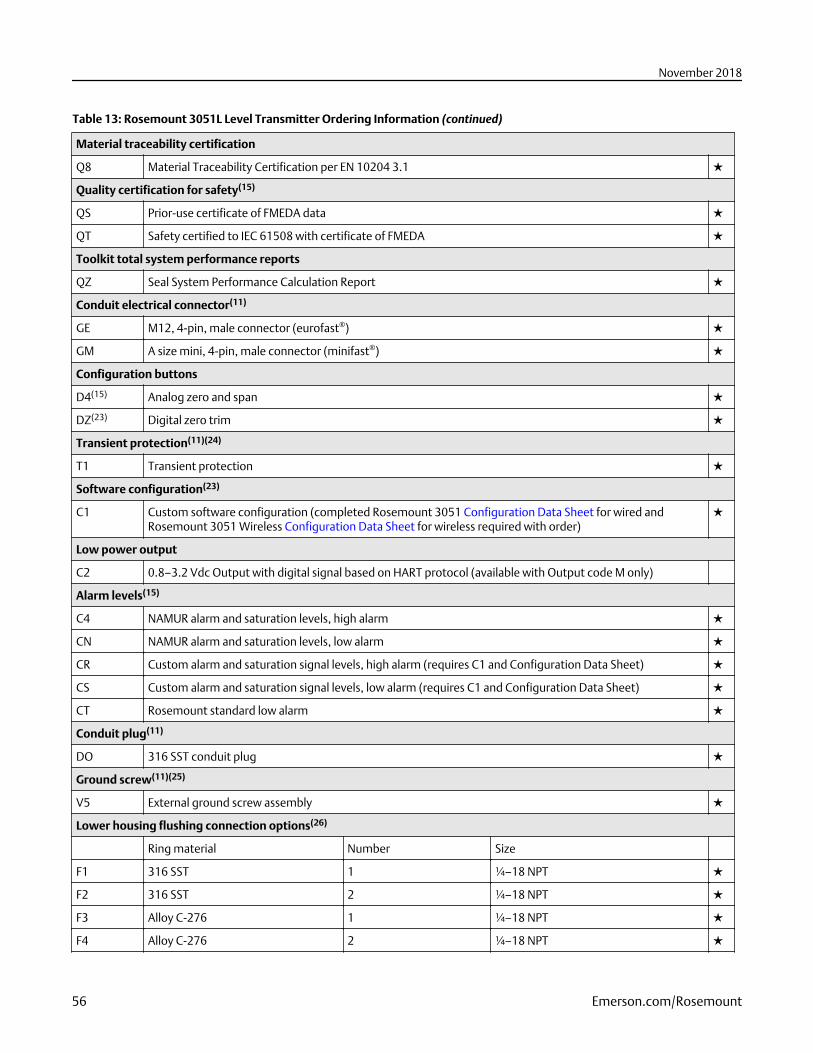
Table 13: Rosemount 3051L Level Transmitter Ordering Information (continued)
Material traceability certification
Q8 Material Traceability Certification per EN 10204 3.1 ★
Quality certification for safety(15)
QS Prior-use certificate of FMEDA data ★
QT Safety certified to IEC 61508 with certificate of FMEDA ★
Toolkit total system performance reports
QZ Seal System Performance Calculation Report ★
Conduit electrical connector(11)
GE M12, 4-pin, male connector (eurofast®) ★
GM A size mini, 4-pin, male connector (minifast®) ★
Configuration buttons
D4(15) Analog zero and span ★
DZ(23) Digital zero trim ★
Transient protection(11)(24)
T1 Transient protection ★
Software configuration(23)
C1 Custom software configuration (completed Rosemount 3051 Configuration Data Sheet for wired andRosemount 3051 Wireless Configuration Data Sheet for wireless required with order)
★
Low power output
C2 0.8–3.2 Vdc Output with digital signal based on HART protocol (available with Output code M only)
Alarm levels(15)
C4 NAMUR alarm and saturation levels, high alarm ★
CN NAMUR alarm and saturation levels, low alarm ★
CR Custom alarm and saturation signal levels, high alarm (requires C1 and Configuration Data Sheet) ★
CS Custom alarm and saturation signal levels, low alarm (requires C1 and Configuration Data Sheet) ★
CT Rosemount standard low alarm ★
Conduit plug(11)
DO 316 SST conduit plug ★
Ground screw(11)(25)
V5 External ground screw assembly ★
Lower housing flushing connection options(26)
Ring material Number Size
F1 316 SST 1 ¼–18 NPT ★
F2 316 SST 2 ¼–18 NPT ★
F3 Alloy C-276 1 ¼–18 NPT ★
F4 Alloy C-276 2 ¼–18 NPT ★
November 2018
56 Emerson.com/Rosemount
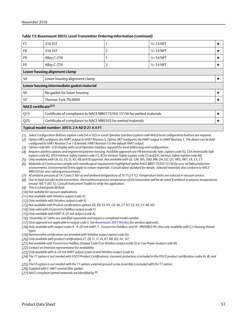
Table 13: Rosemount 3051L Level Transmitter Ordering Information (continued)
F7 316 SST 1 ½–14 NPT ★
F8 316 SST 2 ½–14 NPT ★
F9 Alloy C-276 1 ½–14 NPT ★
F0 Alloy C-276 2 ½–14 NPT ★
Lower housing alignment clamp
SA Lower housing alignment clamp ★
Lower housing intermediate gasket material
S0 No gasket for lower housing ★
SY Thermo-Tork TN-9000 ★
NACE certificate(27)
Q15 Certificate of compliance to NACE MR0175/ISO 15156 for wetted materials ★
Q25 Certificate of compliance to NACE MR0103 for wetted materials ★
Typical model number: 3051L 2 A A0 D 21 A A F1
(1) Select Configuration Buttons (option code D4 or DZ) or Local Operator Interface (option code M4) if local configuration buttons are required.(2) Option HR5 configures the HART output to HART Revision 5. Option HR7 configures the HART output to HART Revision 7. The device can be field
configured to HART Revision 5 or 7 if desired. HART Revision 5 is the default HART output.(3) Option code M4 - LCD Display with Local Operator Interface required for local addressing and configuration.(4) Requires wireless options and engineered polymer housing. Available approvals are FM Intrinsically Safe, (option code I5), CSA Intrinsically Safe
(option code I6), ATEX Intrinsic Safety (option code I1), IECEx Intrinsic Safety (option code I7) and EAC Intrinsic Safety (option code IM).(5) Only available with C6, E2, E5, I5, K5, KB and E8 approval. Not available with GE, GM, SBS, DA0, M4, D4, DZ, QT, HR5, HR7, CR, CS, CT.(6) Materials of Construction comply with metallurgical requirements highlighted within NACE MR0175/ISO 15156 for sour oil field production
environments. Environmental limits apply to certain materials. Consult latest standard for details. Selected materials also conform to NACEMR0103 for sour refining environments.
(7) At ambient pressure of 14.7 psia (1 bar-a) and ambient temperature of 70 °F (21 °C). Temperature limits are reduced in vacuum service.(8) Due to heat transfer to the transmitter, the maximum process temperature of the transmitter will be de-rated if ambient or process temperatures
exceed 185 °F (85 °C). Consult Instrument Toolkit to verify the application.(9) This is a food grade fill fluid.(10) Not suitable for vacuum applications.(11) Not available with Wireless output (code X).(12) Only available with Wireless output (code X).(13) Not available with Product certifications options E8, K8, E5, K5, C6, K6, E7, K7, E2, K2, E3, KB, KD.(14) Only valid with FOUNDATION Fieldbus output (code F).(15) Only available with HART 4–20 mA output (code A).(16) “Assemble-to” items are specified separately and require a completed model number.(17) Dust approval not applicable to output code X. See Rosemount 3051 Wireless for wireless approvals.(18) Only available with output codes A - 4–20 mA HART, F - FOUNDATION Fieldbus, and W - PROFIBUS PA. Also only available with G½ housing thread
types.(19) Nonincendive certification not provided with Wireless output option code (X).(20) Only available with product certifications E7, E8, I1, I7, IA, K7, K8, KD, N1, N7.(21) Not available with FOUNDATION Fieldbus (Output Code F) or Wireless output (code X) or Low Power (output code M).(22) Contact an Emerson representative for availability.(23) Only available with 4–20 mA HART output (code A) and Wireless output (code X).(24) The T1 option is not needed with FISCO Product Certifications; transient protection is included in the FISCO product certification codes IA, IB, and
IE.(25) The V5 option is not needed with the T1 option; external ground screw assembly is included with the T1 option.(26) Supplied with C-4401 aramid fiber gasket.(27) NACE compliant wetted materials are identified by (6).
November 2018
Product Data Sheet 57
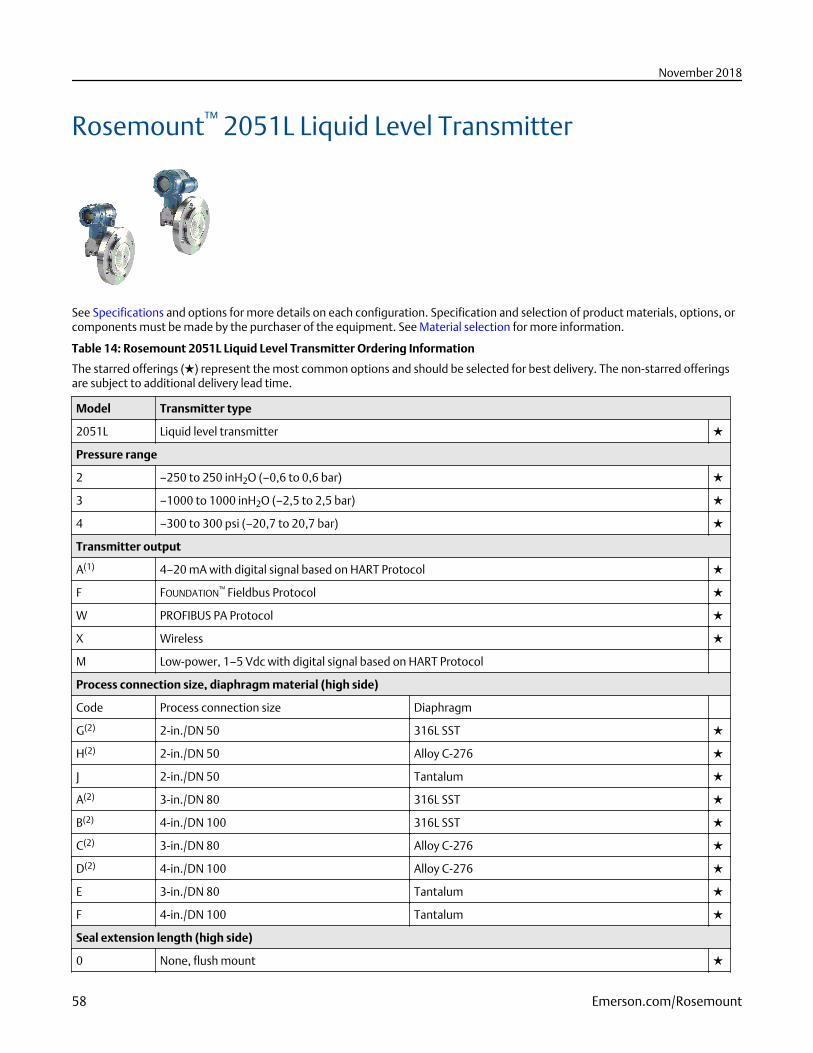
Rosemount™ 2051L Liquid Level Transmitter
See Specifications and options for more details on each configuration. Specification and selection of product materials, options, orcomponents must be made by the purchaser of the equipment. See Material selection for more information.
Table 14: Rosemount 2051L Liquid Level Transmitter Ordering Information
The starred offerings (★) represent the most common options and should be selected for best delivery. The non-starred offeringsare subject to additional delivery lead time.
Model Transmitter type
2051L Liquid level transmitter ★
Pressure range
2 –250 to 250 inH2O (–0,6 to 0,6 bar) ★
3 –1000 to 1000 inH2O (–2,5 to 2,5 bar) ★
4 –300 to 300 psi (–20,7 to 20,7 bar) ★
Transmitter output
A(1) 4–20 mA with digital signal based on HART Protocol ★
F FOUNDATION™ Fieldbus Protocol ★
W PROFIBUS PA Protocol ★
X Wireless ★
M Low-power, 1–5 Vdc with digital signal based on HART Protocol
Process connection size, diaphragm material (high side)
Code Process connection size Diaphragm
G(2) 2-in./DN 50 316L SST ★
H(2) 2-in./DN 50 Alloy C-276 ★
J 2-in./DN 50 Tantalum ★
A(2) 3-in./DN 80 316L SST ★
B(2) 4-in./DN 100 316L SST ★
C(2) 3-in./DN 80 Alloy C-276 ★
D(2) 4-in./DN 100 Alloy C-276 ★
E 3-in./DN 80 Tantalum ★
F 4-in./DN 100 Tantalum ★
Seal extension length (high side)
0 None, flush mount ★
November 2018
58 Emerson.com/Rosemount
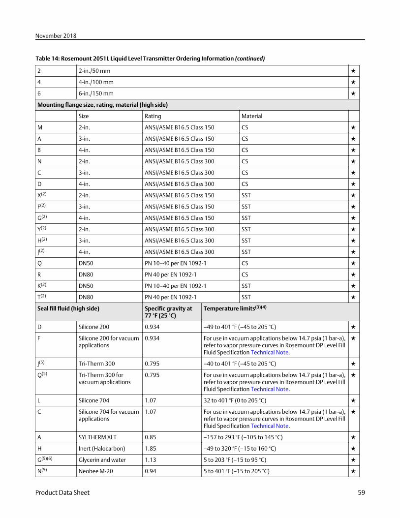
Table 14: Rosemount 2051L Liquid Level Transmitter Ordering Information (continued)
2 2-in./50 mm ★
4 4-in./100 mm ★
6 6-in./150 mm ★
Mounting flange size, rating, material (high side)
Size Rating Material
M 2-in. ANSI/ASME B16.5 Class 150 CS ★
A 3-in. ANSI/ASME B16.5 Class 150 CS ★
B 4-in. ANSI/ASME B16.5 Class 150 CS ★
N 2-in. ANSI/ASME B16.5 Class 300 CS ★
C 3-in. ANSI/ASME B16.5 Class 300 CS ★
D 4-in. ANSI/ASME B16.5 Class 300 CS ★
X(2) 2-in. ANSI/ASME B16.5 Class 150 SST ★
F(2) 3-in. ANSI/ASME B16.5 Class 150 SST ★
G(2) 4-in. ANSI/ASME B16.5 Class 150 SST ★
Y(2) 2-in. ANSI/ASME B16.5 Class 300 SST ★
H(2) 3-in. ANSI/ASME B16.5 Class 300 SST ★
J(2) 4-in. ANSI/ASME B16.5 Class 300 SST ★
Q DN50 PN 10–40 per EN 1092-1 CS ★
R DN80 PN 40 per EN 1092-1 CS ★
K(2) DN50 PN 10–40 per EN 1092-1 SST ★
T(2) DN80 PN 40 per EN 1092-1 SST ★
Seal fill fluid (high side) Specific gravity at77 °F (25 °C)
Temperature limits(3)(4)
D Silicone 200 0.934 –49 to 401 °F (–45 to 205 °C) ★
F Silicone 200 for vacuumapplications
0.934 For use in vacuum applications below 14.7 psia (1 bar-a),refer to vapor pressure curves in Rosemount DP Level FillFluid Specification Technical Note.
★
J(5) Tri-Therm 300 0.795 –40 to 401 °F (–45 to 205 °C) ★
Q(5) Tri-Therm 300 forvacuum applications
0.795 For use in vacuum applications below 14.7 psia (1 bar-a),refer to vapor pressure curves in Rosemount DP Level FillFluid Specification Technical Note.
★
L Silicone 704 1.07 32 to 401 °F (0 to 205 °C) ★
C Silicone 704 for vacuumapplications
1.07 For use in vacuum applications below 14.7 psia (1 bar-a),refer to vapor pressure curves in Rosemount DP Level FillFluid Specification Technical Note.
★
A SYLTHERM XLT 0.85 –157 to 293 °F (–105 to 145 °C) ★
H Inert (Halocarbon) 1.85 –49 to 320 °F (–15 to 160 °C) ★
G(5)(6) Glycerin and water 1.13 5 to 203 °F (–15 to 95 °C) ★
N(5) Neobee M-20 0.94 5 to 401 °F (–15 to 205 °C) ★
November 2018
Product Data Sheet 59
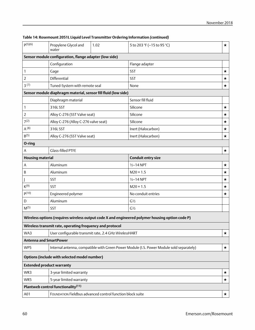
Table 14: Rosemount 2051L Liquid Level Transmitter Ordering Information (continued)
P(5)(6) Propylene Glycol andwater
1.02 5 to 203 °F (–15 to 95 °C) ★
Sensor module configuration, flange adapter (low side)
Configuration Flange adapter
1 Gage SST ★
2 Differential SST ★
3 (7) Tuned-System with remote seal None ★
Sensor module diaphragm material, sensor fill fluid (low side)
Diaphragm material Sensor fill fluid
1 316L SST Silicone ★
2 Alloy C-276 (SST Valve seat) Silicone ★
7(2) Alloy C-276 (Alloy C-276 valve seat) Silicone ★
A (8) 316L SST Inert (Halocarbon) ★
B(5) Alloy C-276 (SST Valve seat) Inert (Halocarbon) ★
O-ring
A Glass-filled PTFE ★
Housing material Conduit entry size
A Aluminum ½–14 NPT ★
B Aluminum M20 × 1.5 ★
J SST ½–14 NPT ★
K(9) SST M20 × 1.5 ★
P(10) Engineered polymer No conduit entries ★
D Aluminum G½
M(5) SST G½
Wireless options (requires wireless output code X and engineered polymer housing option code P)
Wireless transmit rate, operating frequency and protocol
WA3 User configurable transmit rate, 2.4 GHz WirelessHART ★
Antenna and SmartPower
WP5 Internal antenna, compatible with Green Power Module (I.S. Power Module sold separately) ★
Options (include with selected model number)
Extended product warranty
WR3 3-year limited warranty ★
WR5 5-year limited warranty ★
Plantweb control functionality(11)
A01 FOUNDATION Fieldbus advanced control function block suite ★
November 2018
60 Emerson.com/Rosemount
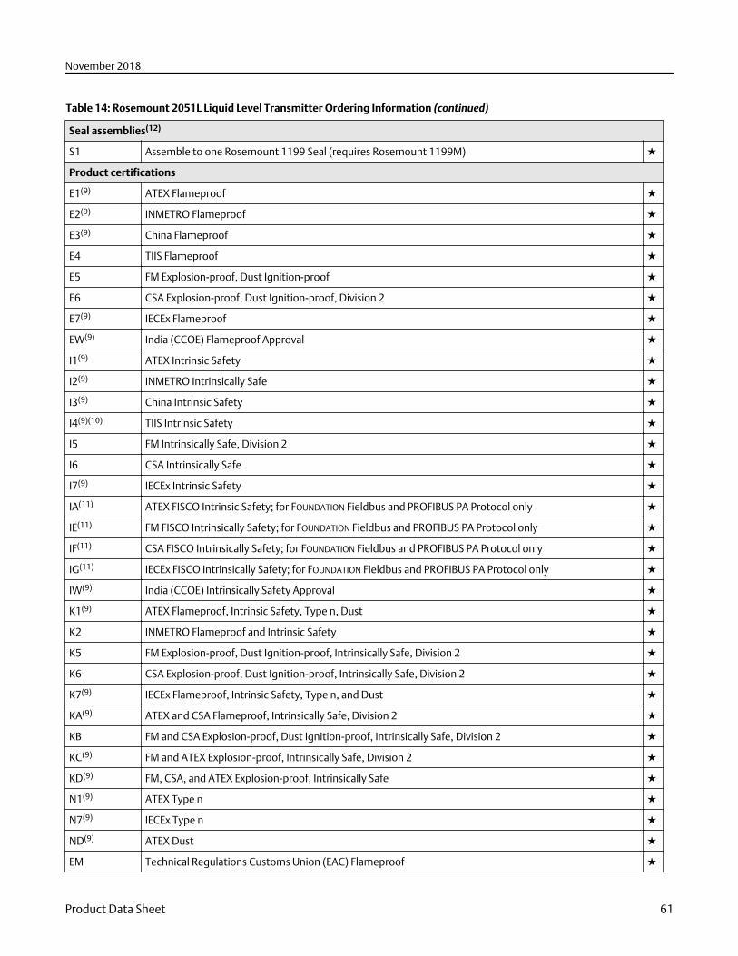
Table 14: Rosemount 2051L Liquid Level Transmitter Ordering Information (continued)
Seal assemblies(12)
S1 Assemble to one Rosemount 1199 Seal (requires Rosemount 1199M) ★
Product certifications
E1(9) ATEX Flameproof ★
E2(9) INMETRO Flameproof ★
E3(9) China Flameproof ★
E4 TIIS Flameproof ★
E5 FM Explosion-proof, Dust Ignition-proof ★
E6 CSA Explosion-proof, Dust Ignition-proof, Division 2 ★
E7(9) IECEx Flameproof ★
EW(9) India (CCOE) Flameproof Approval ★
I1(9) ATEX Intrinsic Safety ★
I2(9) INMETRO Intrinsically Safe ★
I3(9) China Intrinsic Safety ★
I4(9)(10) TIIS Intrinsic Safety ★
I5 FM Intrinsically Safe, Division 2 ★
I6 CSA Intrinsically Safe ★
I7(9) IECEx Intrinsic Safety ★
IA(11) ATEX FISCO Intrinsic Safety; for FOUNDATION Fieldbus and PROFIBUS PA Protocol only ★
IE(11) FM FISCO Intrinsically Safety; for FOUNDATION Fieldbus and PROFIBUS PA Protocol only ★
IF(11) CSA FISCO Intrinsically Safety; for FOUNDATION Fieldbus and PROFIBUS PA Protocol only ★
IG(11) IECEx FISCO Intrinsically Safety; for FOUNDATION Fieldbus and PROFIBUS PA Protocol only ★
IW(9) India (CCOE) Intrinsically Safety Approval ★
K1(9) ATEX Flameproof, Intrinsic Safety, Type n, Dust ★
K2 INMETRO Flameproof and Intrinsic Safety ★
K5 FM Explosion-proof, Dust Ignition-proof, Intrinsically Safe, Division 2 ★
K6 CSA Explosion-proof, Dust Ignition-proof, Intrinsically Safe, Division 2 ★
K7(9) IECEx Flameproof, Intrinsic Safety, Type n, and Dust ★
KA(9) ATEX and CSA Flameproof, Intrinsically Safe, Division 2 ★
KB FM and CSA Explosion-proof, Dust Ignition-proof, Intrinsically Safe, Division 2 ★
KC(9) FM and ATEX Explosion-proof, Intrinsically Safe, Division 2 ★
KD(9) FM, CSA, and ATEX Explosion-proof, Intrinsically Safe ★
N1(9) ATEX Type n ★
N7(9) IECEx Type n ★
ND(9) ATEX Dust ★
EM Technical Regulations Customs Union (EAC) Flameproof ★
November 2018
Product Data Sheet 61
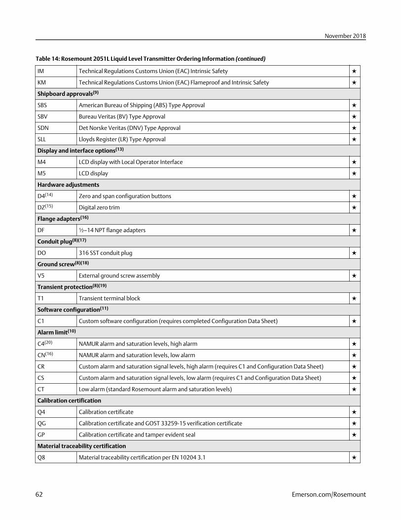
Table 14: Rosemount 2051L Liquid Level Transmitter Ordering Information (continued)
IM Technical Regulations Customs Union (EAC) Intrinsic Safety ★
KM Technical Regulations Customs Union (EAC) Flameproof and Intrinsic Safety ★
Shipboard approvals(9)
SBS American Bureau of Shipping (ABS) Type Approval ★
SBV Bureau Veritas (BV) Type Approval ★
SDN Det Norske Veritas (DNV) Type Approval ★
SLL Lloyds Register (LR) Type Approval ★
Display and interface options(13)
M4 LCD display with Local Operator Interface ★
M5 LCD display ★
Hardware adjustments
D4(14) Zero and span configuration buttons ★
DZ(15) Digital zero trim ★
Flange adapters(16)
DF ½–14 NPT flange adapters ★
Conduit plug(8)(17)
DO 316 SST conduit plug ★
Ground screw(8)(18)
V5 External ground screw assembly ★
Transient protection(8)(19)
T1 Transient terminal block ★
Software configuration(11)
C1 Custom software configuration (requires completed Configuration Data Sheet) ★
Alarm limit(10)
C4(20) NAMUR alarm and saturation levels, high alarm ★
CN(16) NAMUR alarm and saturation levels, low alarm ★
CR Custom alarm and saturation signal levels, high alarm (requires C1 and Configuration Data Sheet) ★
CS Custom alarm and saturation signal levels, low alarm (requires C1 and Configuration Data Sheet) ★
CT Low alarm (standard Rosemount alarm and saturation levels) ★
Calibration certification
Q4 Calibration certificate ★
QG Calibration certificate and GOST 33259-15 verification certificate ★
GP Calibration certificate and tamper evident seal ★
Material traceability certification
Q8 Material traceability certification per EN 10204 3.1 ★
November 2018
62 Emerson.com/Rosemount
Table 14: Rosemount 2051L Liquid Level Transmitter Ordering Information (continued)
Quality certification for safety(21)
QS Prior-use certificate of FMEDA data ★
QT Safety certified to IEC 61508 with certificate of FMEDA ★
Toolkit total system performance reports
QZ Remote seal system performance calculation report ★
Conduit electrical connector(8)
GE M12, 4-pin, male connector (eurofast®) ★
GM A size mini, 4-pin, male connector (minifast®) ★
Lower housing flushing connection options(22)
Ring material Number Size
F1 316 SST 1 ¼–18 NPT ★
F2 316 SST 2 ¼–18 NPT ★
F3(23) Alloy C-276 1 ¼–18 NPT ★
F4(23) Alloy C-276 2 ¼–18 NPT ★
F7 316 SST 1 ½–14 NPT ★
F8 316 SST 2 ½–14 NPT ★
F9 Alloy C-276 1 ½–14 NPT ★
F0 Alloy C-276 2 ½–14 NPT ★
Lower housing alignment clamp
SA Lower housing alignment clamp ★
Lower housing intermediate gasket material
S0 No gasket for lower housing ★
SY Thermo-Tork TN-9000 ★
NACE certificate
Q15(24) Certificate of compliance to NACE MR0175/ISO 15156 for wetted materials ★
Q25 Certificate of compliance to NACE MR0103 for wetted materials ★
Typical model number: 2051L 2 A A0 X D 21 A A B4 M5 F1
(1) HART Revision 5 is the default HART output. The Rosemount 2051 with Selectable HART can be factory or field configured to HART Revision 7. Toorder HART Revision 7 factory configured, add option code HR7.
(2) Materials of Construction comply with metallurgical requirements highlighted within NACE MR0175/ISO 15156 for sour oil field productionenvironments. Environmental limits apply to certain materials. Consult latest standard for details. Selected materials also conform to NACEMR0103 for sour refining environments. Order with Q15 or Q25 to receive a NACE certificate.
(3) At ambient pressure of 14.7 psia (1 bar-a) and ambient temperature of 70 °F (21 °C). Temperature limits are reduced in vacuum service.(4) Due to heat transfer to the transmitter, the maximum process temperature of the transmitter will be de-rated if ambient or process temperatures
exceed 185 °F (85 °C). Consult Instrument Toolkit to verify the application.(5) This is a food grade fill fluid.(6) Not suitable for vacuum applications.(7) Requires option code S1.(8) Not available with output code X.(9) Not available with Low Power output code m.(10) Only available with output code X.(11) Only valid with FOUNDATION Fieldbus output code F.
November 2018
Product Data Sheet 63
(12) “Assemble-to” items are specified separately and require a completed model number.(13) Not valid with FOUNDATION Fieldbus output code F and Wireless Output Code X.(14) Only available with 4–20 mA HART (output codes A and M).(15) Only available with HART 4–20 mA output (output codes A) and Wireless output (output code X).(16) Not available with Remote Mount Seal Assembly option S1.(17) Transmitter is shipped with 316 SST conduit plug (uninstalled) in place of standard carbon steel conduit plug.(18) The V5 option is not needed with the T1 option; external ground screw assembly is included with the T1 option.(19) The T1 option is not needed with FISCO Product Certifications; transient protection is included in the FISCO product certification codes IA, IE, IF,
and IG.(20) NAMUR-Compliant operation is pre-set at the factory.(21) Only available with HART 4–20 mA output (output code A).(22) Supplied with C-4401 aramid fiber gasket.(23) Not available with Option Codes A0, B0, and G0.(24) NACE Compliant wetted materials are identified by (2).
November 2018
64 Emerson.com/Rosemount
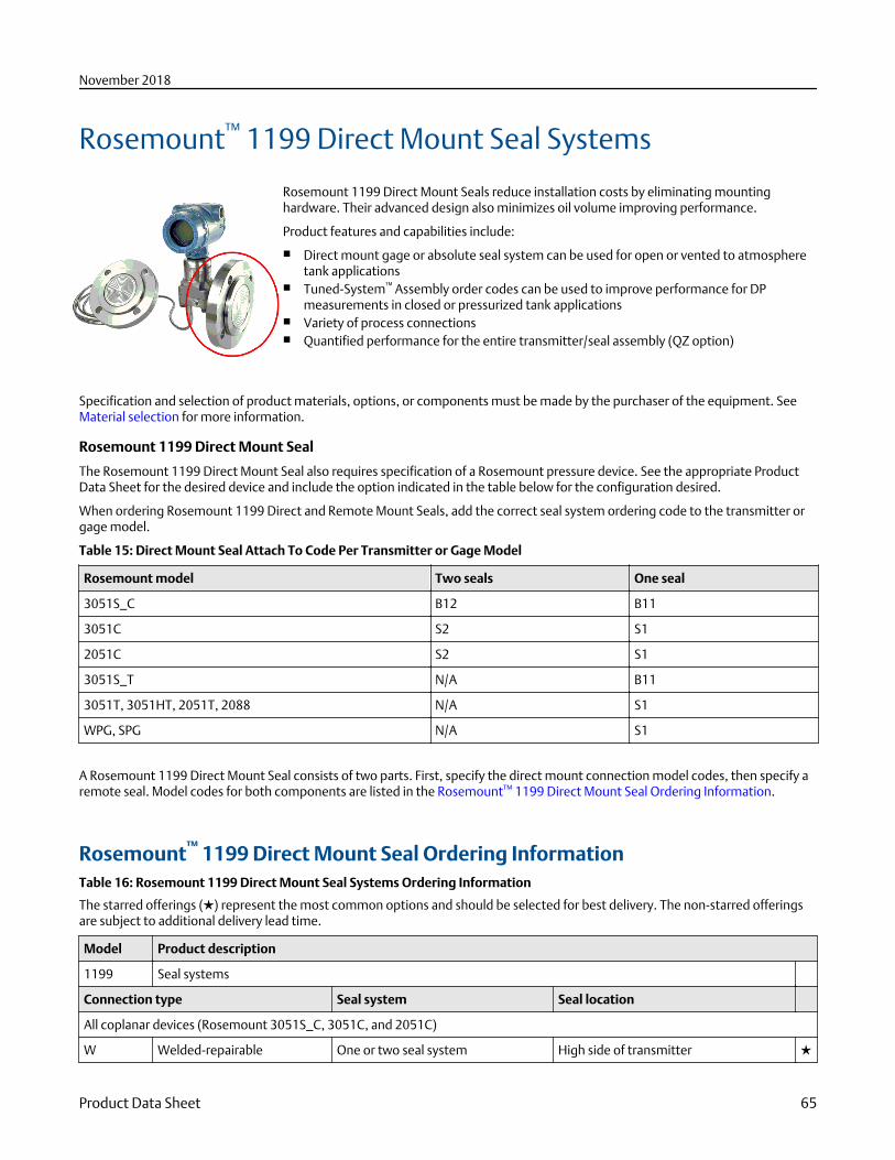
Rosemount™ 1199 Direct Mount Seal Systems
Rosemount 1199 Direct Mount Seals reduce installation costs by eliminating mountinghardware. Their advanced design also minimizes oil volume improving performance.
Product features and capabilities include:
■ Direct mount gage or absolute seal system can be used for open or vented to atmospheretank applications
■ Tuned-System™ Assembly order codes can be used to improve performance for DPmeasurements in closed or pressurized tank applications
■ Variety of process connections■ Quantified performance for the entire transmitter/seal assembly (QZ option)
Specification and selection of product materials, options, or components must be made by the purchaser of the equipment. SeeMaterial selection for more information.
Rosemount 1199 Direct Mount Seal
The Rosemount 1199 Direct Mount Seal also requires specification of a Rosemount pressure device. See the appropriate ProductData Sheet for the desired device and include the option indicated in the table below for the configuration desired.
When ordering Rosemount 1199 Direct and Remote Mount Seals, add the correct seal system ordering code to the transmitter orgage model.
Table 15: Direct Mount Seal Attach To Code Per Transmitter or Gage Model
Rosemount model Two seals One seal
3051S_C B12 B11
3051C S2 S1
2051C S2 S1
3051S_T N/A B11
3051T, 3051HT, 2051T, 2088 N/A S1
WPG, SPG N/A S1
A Rosemount 1199 Direct Mount Seal consists of two parts. First, specify the direct mount connection model codes, then specify aremote seal. Model codes for both components are listed in the Rosemount™ 1199 Direct Mount Seal Ordering Information.
Rosemount™ 1199 Direct Mount Seal Ordering InformationTable 16: Rosemount 1199 Direct Mount Seal Systems Ordering Information
The starred offerings (★) represent the most common options and should be selected for best delivery. The non-starred offeringsare subject to additional delivery lead time.
Model Product description
1199 Seal systems
Connection type Seal system Seal location
All coplanar devices (Rosemount 3051S_C, 3051C, and 2051C)
W Welded-repairable One or two seal system High side of transmitter ★
November 2018
Product Data Sheet 65
Table 16: Rosemount 1199 Direct Mount Seal Systems Ordering Information (continued)
R(1) All welded One seal system High side of transmitter ★
T(1) All welded Two seal system High side of transmitter ★
All In-line devices (Rosemount 3051S_T, 3051T, 3051HT, 2051T, 2088, WPG and SPG)
W All welded One seal system N/A ★
Seal fill fluid Specificgravity at77 °F (25 °C)
Temperature limits(2)(3)
No extension 2-in. (50 mm)extension
4-in. (100 mm)extension
ThermalOptimizer
D Silicone 200 0.934 –49 to 401 °F
(–45 to 205 °C)
–49 to 401 °F
(–45 to 205 °C)
–49 to 401 °F
(–45 to 205 °C)
–49 to 401 °F
(–45 to 205 °C)
★
F Silicone 200for vacuumapplications
0.934 For use in vacuum applications below 14.7 psia (1 bar-a), refer to vapor pressurecurves in Rosemount DP Level Fill Fluid Specification Technical Note.
★
J(4) Tri-Therm 300 0.795 –40 to 401 °F
(–40 to 205 °C)
–40 to 464 °F
(–40 to 240 °C)
–40 to 572 °F
(–40 to 300 °C)
N/A ★
Q(4) Tri-Therm 300for vacuumApplications
0.795 For use in vacuum applications below 14.7 psia (1 bar-a), refer to vapor pressurecurves in Rosemount DP Level Fill Fluid Specification Technical Note.
★
L Silicone 704 1.07 32 to 401 °F
(0 to 205 °C)
32 to 464 °F
(0 to 240 °C)
32 to 572 °F
(0 to 300 °C)
32 to 599 °F
(0 to 315 °C)
★
C Silicone 704for vacuumapplications
1.07 For use in vacuum applications below 14.7 psia (1 bar-a), refer to vapor pressurecurves in Rosemount DP Level Fill Fluid Specification Technical Note.
★
R Silicone 705 1.09 68 to 401 °F
(20 to 205 °C)
68 to 464 °F (20 to240 °C)
68 to 572 °F (20 to300 °C)
68 to 698 °F (20to 370 °C)
★
V Silicone 705for vacuumapplications
1.09 For use in vacuum applications below 14.7 psia (1 bar-a), refer to vapor pressurecurves in Rosemount DP Level Fill Fluid Specification Technical Note.
★
A SYLTHERM XLT 0.85 –157 to 293 °F
(–105 to 145°C)
–157 to 293 °F
(–105 to 145 °C)
–157 to 293 °F
(–105 to 145 °C)
–157 to 293 °F
(–105 to 145 °C)
★
H Inert(Halocarbon)
1.85 –49 to 320 °F
(–45 to 160 °C)
–49 to 320 °F
(–45 to 160 °C)
–49 to 320 °F
(–45 to 160 °C)
–49 to 320 °F
(–45 to 160 °C)
★
G(4)(5) Glycerine andwater
1.13 5 to 203 °F
(–15 to 95 °C)
5 to 203 °F
(–15 to 95 °C)
5 to 203 °F
(–15 to 95 °C)
5 to 203 °F
(–15 to 95 °C)
★
N(4) Neobee M-20 0.94 5 to 401 °F
(–15 to 205 °C)
5 to 437 °F
(–15 to 225 °C)
5 to 437 °F
(–15 to 225 °C)
5 to 437 °F
(–15 to 225 °C)
★
P(4)(5) PropyleneGlycol andwater
1.02 5 to 203 °F
(–15 to 95 °C)
5 to 203 °F
(–15 to 95 °C)
5 to 203 °F
(–15 to 95 °C)
5 to 203 °F
(–15 to 95 °C)
★
November 2018
66 Emerson.com/Rosemount
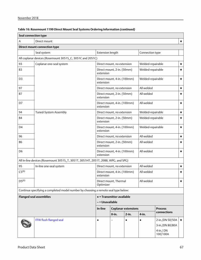
Table 16: Rosemount 1199 Direct Mount Seal Systems Ordering Information (continued)
Seal connection type
A Direct mount ★
Direct mount connection type
Seal system Extension length Connection type
All coplanar devices (Rosemount 3051S_C, 3051C and 2051C)
93 Coplanar one-seal system Direct mount, no extension Welded-repairable ★
B3 Direct mount, 2-in. (50mm)extension
Welded-repairable ★
D3 Direct mount, 4-in. (100mm)extension
Welded-repairable ★
97 Direct mount, no extension All welded ★
B7 Direct mount, 2-in. (50mm)extension
All welded ★
D7 Direct mount, 4-in. (100mm)extension
All welded ★
94 Tuned-System Assembly Direct mount, no extension Welded-repairable ★
B4 Direct mount, 2-in. (50mm)extension
Welded-repairable ★
D4 Direct mount, 4-in. (100mm)extension
Welded-repairable ★
96 Direct mount, no extension All welded ★
B6 Direct mount, 2-in. (50mm)extension
All welded ★
D6 Direct mount, 4-in. (100mm)extension
All welded ★
All In-line devices (Rosemount 3051S_T, 3051T, 3051HT, 2051T, 2088, WPG, and SPG)
95 In-line one-seal system Direct mount, no extension All welded ★
C5(6) Direct mount, 4-in. (100mm)extension
All welded ★
D5(6) Direct mount, ThermalOptimizer
All welded ★
Continue specifying a completed model number by choosing a remote seal type below:
Flanged seal assemblies ● = Transmitter available
– = Unavailable
In-line Coplanar extensions Processconnections
0-in. 2-in. 4-in.
FFW flush flanged seal ● – ● ● 2-in./DN 50/50A
3-in./DN 80/80A
4-in./ DN100/100A
★
November 2018
Product Data Sheet 67
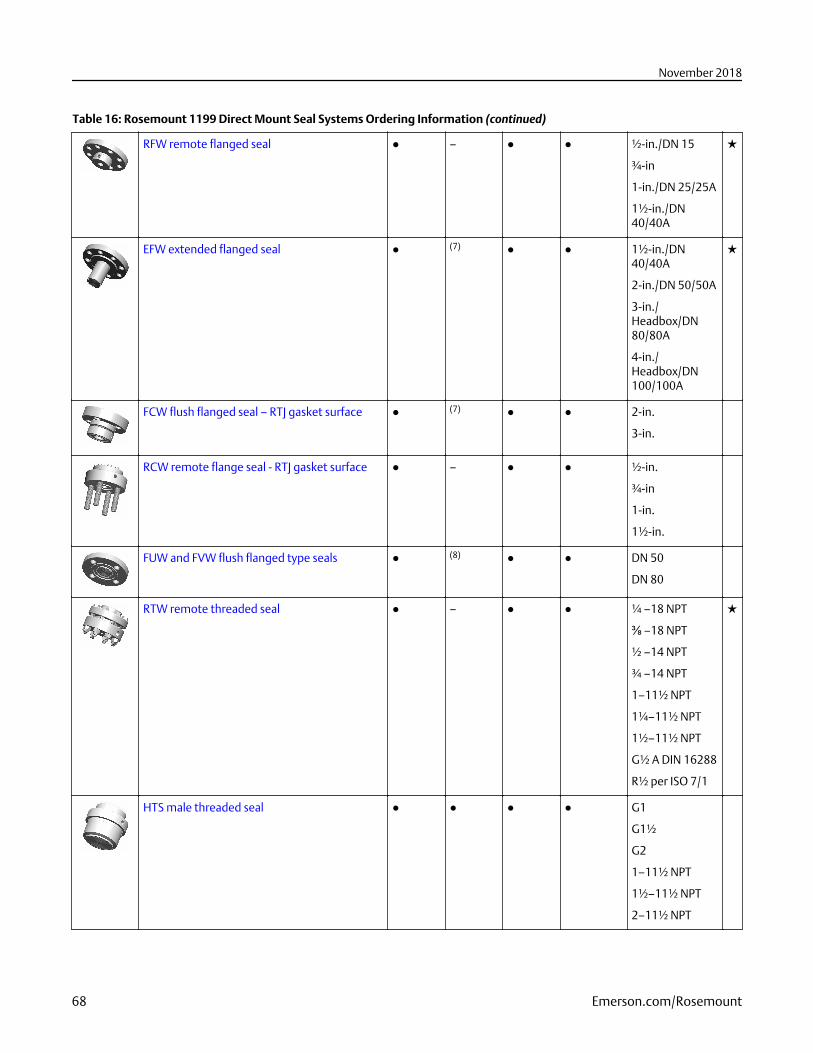
Table 16: Rosemount 1199 Direct Mount Seal Systems Ordering Information (continued)
RFW remote flanged seal ● – ● ● ½-in./DN 15
¾-in
1-in./DN 25/25A
1½-in./DN40/40A
★
EFW extended flanged seal ● (7) ● ● 1½-in./DN40/40A
2-in./DN 50/50A
3-in./Headbox/DN80/80A
4-in./Headbox/DN100/100A
★
FCW flush flanged seal – RTJ gasket surface ● (7) ● ● 2-in.
3-in.
RCW remote flange seal - RTJ gasket surface ● – ● ● ½-in.
¾-in
1-in.
1½-in.
FUW and FVW flush flanged type seals ● (8) ● ● DN 50
DN 80
RTW remote threaded seal ● – ● ● ¼ –18 NPT
⅜ –18 NPT
½ –14 NPT
¾ –14 NPT
1–11½ NPT
1¼–11½ NPT
1½–11½ NPT
G½ A DIN 16288
R½ per ISO 7/1
★
HTS male threaded seal ● ● ● ● G1
G1½
G2
1–11½ NPT
1½–11½ NPT
2–11½ NPT
November 2018
68 Emerson.com/Rosemount
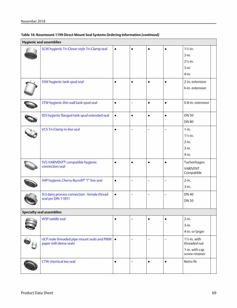
Table 16: Rosemount 1199 Direct Mount Seal Systems Ordering Information (continued)
Hygienic seal assemblies
SCW hygienic Tri-Clover style Tri-Clamp seal ● ● ● ● 1½-in.
2-in.
2½-in.
3-in.
4-in.
SSW hygienic tank spud seal ● ● ● ● 2-in. extension
6-in. extension
STW hygienic thin wall tank spud seal ● – ● ● 0.8-in. extension
EES hygienic flanged tank spud extended seal ● ● ● ● DN 50
DN 80
VCS Tri-Clamp in-line seal ● – – – 1-in.
1½-in.
2-in.
3-in.
4-in.
SVS VARIVENT® compatible hygienicconnection seal
● ● ● ● Tuchenhagen
VARIVENTCompatible
SHP hygienic Cherry-Burrell® “I” line seal ● – – – 2-in.
3-in.
SLS dairy process connection - female threadseal per DIN 11851
● – – – DN 40
DN 50
Specialty seal assemblies
WSP saddle seal ● – ● ● 2-in.
3-in.
4-in. or larger
UCP male threaded pipe mount seals and PMWpaper mill sleeve seals
● – – – 1½-in. withthreaded nut
1-in. with capscrew retainer
CTW chemical tee seal ● – ● ● Retro-fit
November 2018
Product Data Sheet 69
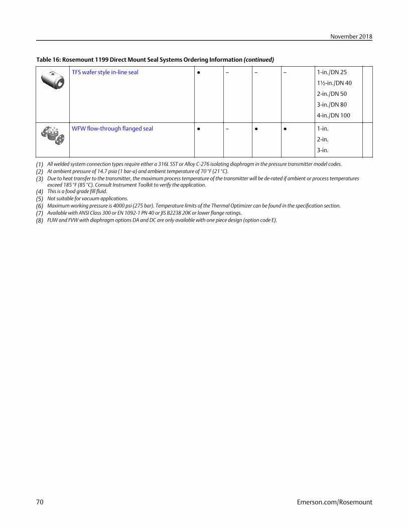
Table 16: Rosemount 1199 Direct Mount Seal Systems Ordering Information (continued)
TFS wafer style in-line seal ● – – – 1-in./DN 25
1½-in./DN 40
2-in./DN 50
3-in./DN 80
4-in./DN 100
WFW flow-through flanged seal ● – ● ● 1-in.
2-in.
3-in.
(1) All welded system connection types require either a 316L SST or Alloy C-276 isolating diaphragm in the pressure transmitter model codes.(2) At ambient pressure of 14.7 psia (1 bar-a) and ambient temperature of 70 °F (21 °C).(3) Due to heat transfer to the transmitter, the maximum process temperature of the transmitter will be de-rated if ambient or process temperatures
exceed 185 °F (85 °C). Consult Instrument Toolkit to verify the application.(4) This is a food grade fill fluid.(5) Not suitable for vacuum applications.(6) Maximum working pressure is 4000 psi (275 bar). Temperature limits of the Thermal Optimizer can be found in the specification section.(7) Available with ANSI Class 300 or EN 1092-1 PN 40 or JIS B2238 20K or lower flange ratings.(8) FUW and FVW with diaphragm options DA and DC are only available with one piece design (option code E).
November 2018
70 Emerson.com/Rosemount
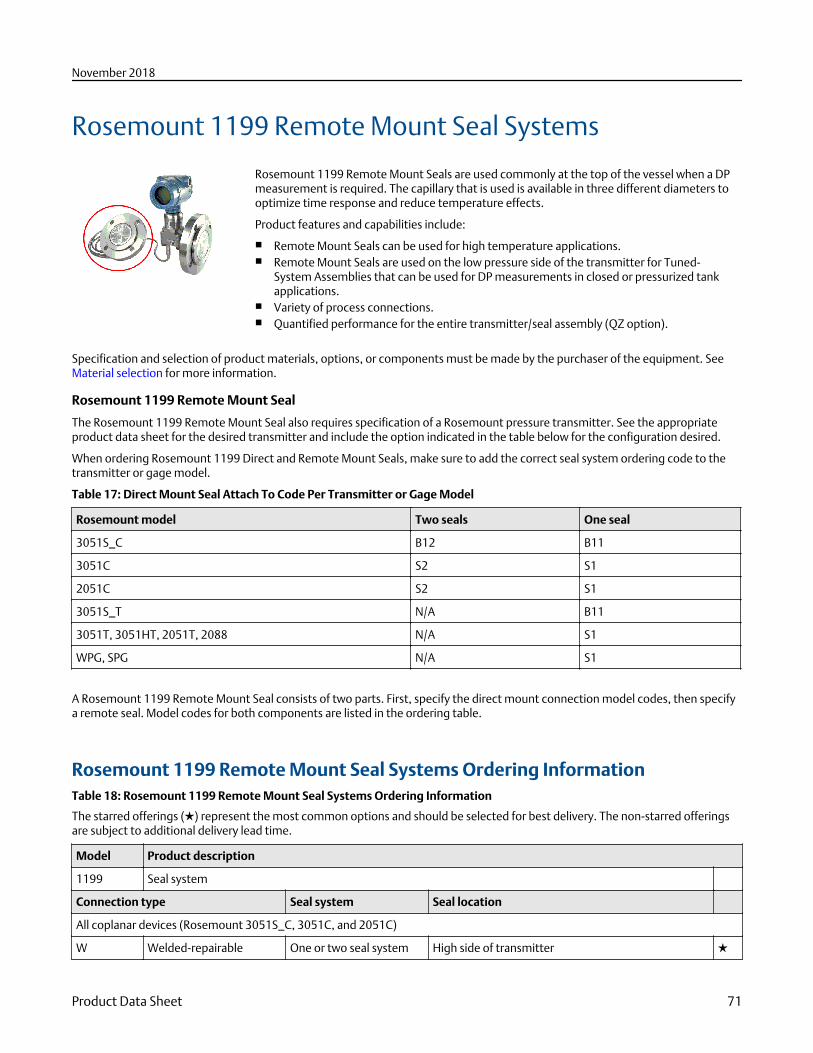
Rosemount 1199 Remote Mount Seal Systems
Rosemount 1199 Remote Mount Seals are used commonly at the top of the vessel when a DPmeasurement is required. The capillary that is used is available in three different diameters tooptimize time response and reduce temperature effects.
Product features and capabilities include:
■ Remote Mount Seals can be used for high temperature applications.■ Remote Mount Seals are used on the low pressure side of the transmitter for Tuned-
System Assemblies that can be used for DP measurements in closed or pressurized tankapplications.
■ Variety of process connections.■ Quantified performance for the entire transmitter/seal assembly (QZ option).
Specification and selection of product materials, options, or components must be made by the purchaser of the equipment. SeeMaterial selection for more information.
Rosemount 1199 Remote Mount Seal
The Rosemount 1199 Remote Mount Seal also requires specification of a Rosemount pressure transmitter. See the appropriateproduct data sheet for the desired transmitter and include the option indicated in the table below for the configuration desired.
When ordering Rosemount 1199 Direct and Remote Mount Seals, make sure to add the correct seal system ordering code to thetransmitter or gage model.
Table 17: Direct Mount Seal Attach To Code Per Transmitter or Gage Model
Rosemount model Two seals One seal
3051S_C B12 B11
3051C S2 S1
2051C S2 S1
3051S_T N/A B11
3051T, 3051HT, 2051T, 2088 N/A S1
WPG, SPG N/A S1
A Rosemount 1199 Remote Mount Seal consists of two parts. First, specify the direct mount connection model codes, then specifya remote seal. Model codes for both components are listed in the ordering table.
Rosemount 1199 Remote Mount Seal Systems Ordering InformationTable 18: Rosemount 1199 Remote Mount Seal Systems Ordering Information
The starred offerings (★) represent the most common options and should be selected for best delivery. The non-starred offeringsare subject to additional delivery lead time.
Model Product description
1199 Seal system
Connection type Seal system Seal location
All coplanar devices (Rosemount 3051S_C, 3051C, and 2051C)
W Welded-repairable One or two seal system High side of transmitter ★
November 2018
Product Data Sheet 71
Table 18: Rosemount 1199 Remote Mount Seal Systems Ordering Information (continued)
M Welded-repairable One or two seal system Low side of transmitter ★
D Welded-repairable Two seal system Balanced system - identical high and low sides ★
R(1) All welded One seal system High side of transmitter ★
T(1) All welded Two seal system High side of transmitter ★
S(1) All welded Two seal system Low side of transmitter ★
All In-line devices (Rosemount 3051S_T, 3051T, 3051HT, 2051T, 2088, WPG, and SPG)
W All welded One seal system N/A ★
Seal fill fluid Specific gravity at 77 °F(25 °C)
Remote mount with capillary temperaturelimits(2)(3)
D Silicone 200 0.934 –49 to 401 °F (–45 to 205 °C) ★
F Silicone 200 for vacuumapplications
0.934 For use in vacuum applications below 14.7 psia (1 bar-a), refer to vapor pressure curves in Rosemount DPLevel Fill Fluid Specification Technical Note.
★
J(6) Tri-Therm 300 0.795 –40 to 572 °F (–40 to 300 °C) ★
Q(6) Tri-Therm 300 forvacuum applications
0.795 For use in vacuum applications below 14.7 psia (1 bar-a), refer to vapor pressure curves in Rosemount DPLevel Fill Fluid Specification Technical Note.
★
L(4) Silicone 704 1.07 32 to 599 °F (0 to 315 °C) ★
C(4) Silicone 704 for vacuumapplications
1.07 For use in vacuum applications below 14.7 psia (1 bar-a), refer to vapor pressure curves in Rosemount DPLevel Fill Fluid Specification Technical Note.
★
R(4) Silicone 705 1.09 68 to 698 °F (20 to 370 °C) ★
V(5) Silicone 705 for vacuumapplications
1.09 For use in vacuum applications below 14.7 psia (1 bar-a), refer to vapor pressure curves in Rosemount DPLevel Fill Fluid Specification Technical Note.
★
A SYLTHERM XLT 0.85 –157 to 293 °F (–105 to 145 °C) ★
H Inert (Halocarbon) 1.85 –49 to 320 °F (–45 to 160 °C) ★
G(6)(7) Glycerin and water 1.13 5 to 203 °F (–15 to 95 °C) ★
N(6) Neobee M-20 0.94 5 to 437 °F (–15 to 225 °C) ★
P(4)(7) Propylene Glycol andwater
1.02 5 to 203 °F (–15 to 95 °C) ★
Seal connection type/capillary ID, description
B 0.03-in. (0,711 mm) ID ★
C 0.04-in. (1,092 mm) ID ★
D 0.075-in. (1,905 mm) ID ★
E(8) 0.03-in. (0,711 mm) ID, PVC coated with closed end ★
F(8) 0.04-in. (1,092 mm) ID, PVC coated with closed end ★
G(8) 0.075-in. (1,905 mm) ID, PVC coated with closed end ★
H 0.03-in. (0,711 mm) ID, 4-in. support tube ★
J 0.04-in. (1,092 mm) ID, 4-in. support tube ★
November 2018
72 Emerson.com/Rosemount
Table 18: Rosemount 1199 Remote Mount Seal Systems Ordering Information (continued)
K 0.075-in. (1,905 mm) ID, 4-in. support tube ★
M(8) 0.03-in. (0,711 mm) ID, PVC coated, 4-in. support tube with closed end ★
N(8) 0.04-in. (1,092 mm) ID, PVC coated, 4-in. support tube with closed end ★
P(8) 0.075-in. (1,905 mm) ID, PVC PVC coated, 4-in. support tube with closed end ★
Capillary length
01 1.0 ft. (0,3 m) ★
05 5.0 ft. (1,5 m) ★
10 10.0 ft. (3,0 m) ★
15 15.0 ft. (4,5 m) ★
20 20.0 ft. (6,1 m) ★
51 1.6 ft. (0,5 m) ★
52 3.3 ft. (1,0 m) ★
53 4.9 ft. (1,5 m) ★
54 6.6 ft. (2,0 m) ★
55 8.2 ft. (2,5 m) ★
56 9.8 ft. (3,0 m) ★
57 11.5 ft. (3,5 m) ★
58 13.1 ft. (4,0 m) ★
59 16.4 ft. (5,0 m) ★
60 19.7 ft. (6,0 m) ★
25 25.0 ft. (7,6 m)
30 30.0 ft. (9,1 m)
35 35.0 ft. (10,7 m)
40 40.0 ft. (12,2 m)
45 45.0 ft. (13,7 m)
50 50.0 ft. (15,2 m)
61 23.0 ft. (7,0 m)
62 26.2 ft. (8,0 m)
63 29.5 ft. (9,0 m)
64 32.8 ft. (10,0 m)
65 36.1 ft. (11,0 m)
66 39.4 ft. (12,0 m)
67 42.6 ft. (13,0 m)
68 45.9 ft. (14,0 m)
69 49.2 ft. (15,0 m)
November 2018
Product Data Sheet 73
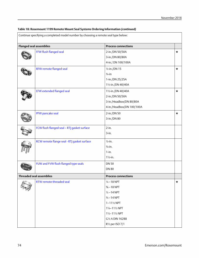
Table 18: Rosemount 1199 Remote Mount Seal Systems Ordering Information (continued)
Continue specifying a completed model number by choosing a remote seal type below:
Flanged seal assemblies Process connections
FFW flush flanged seal 2-in./DN 50/50A
3-in./DN 80/80A
4-in./ DN 100/100A
★
RFW remote flanged seal ½-in./DN 15
¾-in
1-in./DN 25/25A
1½-in./DN 40/40A
★
EFW extended flanged seal 1½-in./DN 40/40A
2-in./DN 50/50A
3-in./Headbox/DN 80/80A
4-in./Headbox/DN 100/100A
★
PFW pancake seal 2-in./DN 50
3-in./DN 80
★
FCW flush flanged seal – RTJ gasket surface 2-in.
3-in.
RCW remote flange seal - RTJ gasket surface ½-in.
¾-in.
1-in.
1½-in.
FUW and FVW flush flanged type seals DN 50
DN 80
Threaded seal assemblies Process connections
RTW remote threaded seal ¼ –18 NPT
⅜ –18 NPT
½ –14 NPT
¾ –14 NPT
1–11½ NPT
1¼–11½ NPT
1½–11½ NPT
G½ A DIN 16288
R½ per ISO 7/1
★
November 2018
74 Emerson.com/Rosemount
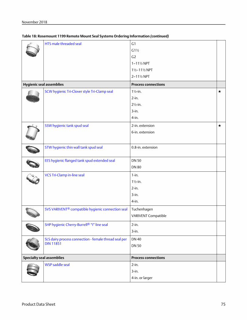
Table 18: Rosemount 1199 Remote Mount Seal Systems Ordering Information (continued)
HTS male threaded seal G1
G1½
G2
1–11½ NPT
1½–11½ NPT
2–11½ NPT
Hygienic seal assemblies Process connections
SCW hygienic Tri-Clover style Tri-Clamp seal 1½-in.
2-in.
2½-in.
3-in.
4-in.
★
SSW hygienic tank spud seal 2-in. extension
6-in. extension
★
STW hygienic thin wall tank spud seal 0.8-in. extension
EES hygienic flanged tank spud extended seal DN 50
DN 80
VCS Tri-Clamp in-line seal 1-in.
1½-in.
2-in.
3-in.
4-in.
SVS VARIVENT® compatible hygienic connection seal Tuchenhagen
VARIVENT Compatible
SHP hygienic Cherry-Burrell® “I” line seal 2-in.
3-in.
SLS dairy process connection - female thread seal perDIN 11851
DN 40
DN 50
Specialty seal assemblies Process connections
WSP saddle seal 2-in.
3-in.
4-in. or larger
November 2018
Product Data Sheet 75
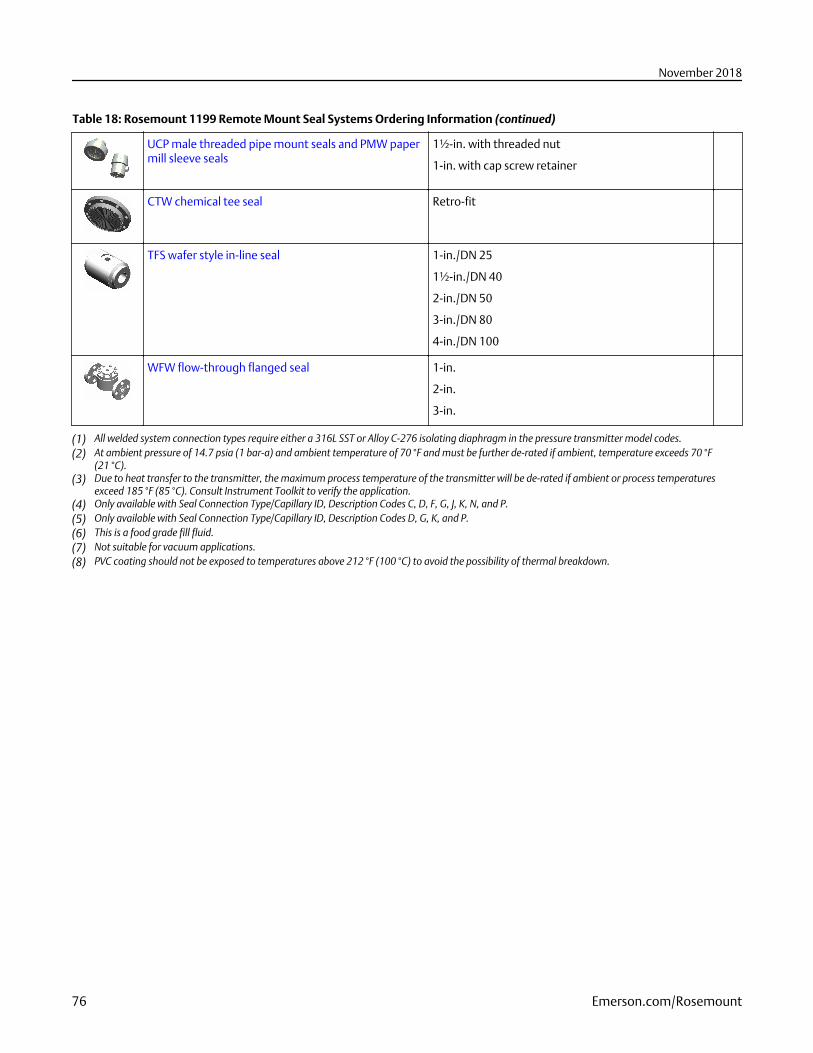
Table 18: Rosemount 1199 Remote Mount Seal Systems Ordering Information (continued)
UCP male threaded pipe mount seals and PMW papermill sleeve seals
1½-in. with threaded nut
1-in. with cap screw retainer
CTW chemical tee seal Retro-fit
TFS wafer style in-line seal 1-in./DN 25
1½-in./DN 40
2-in./DN 50
3-in./DN 80
4-in./DN 100
WFW flow-through flanged seal 1-in.
2-in.
3-in.
(1) All welded system connection types require either a 316L SST or Alloy C-276 isolating diaphragm in the pressure transmitter model codes.(2) At ambient pressure of 14.7 psia (1 bar-a) and ambient temperature of 70 °F and must be further de-rated if ambient, temperature exceeds 70 °F
(21 °C).(3) Due to heat transfer to the transmitter, the maximum process temperature of the transmitter will be de-rated if ambient or process temperatures
exceed 185 °F (85 °C). Consult Instrument Toolkit to verify the application.(4) Only available with Seal Connection Type/Capillary ID, Description Codes C, D, F, G, J, K, N, and P.(5) Only available with Seal Connection Type/Capillary ID, Description Codes D, G, K, and P.(6) This is a food grade fill fluid.(7) Not suitable for vacuum applications.(8) PVC coating should not be exposed to temperatures above 212 °F (100 °C) to avoid the possibility of thermal breakdown.
November 2018
76 Emerson.com/Rosemount
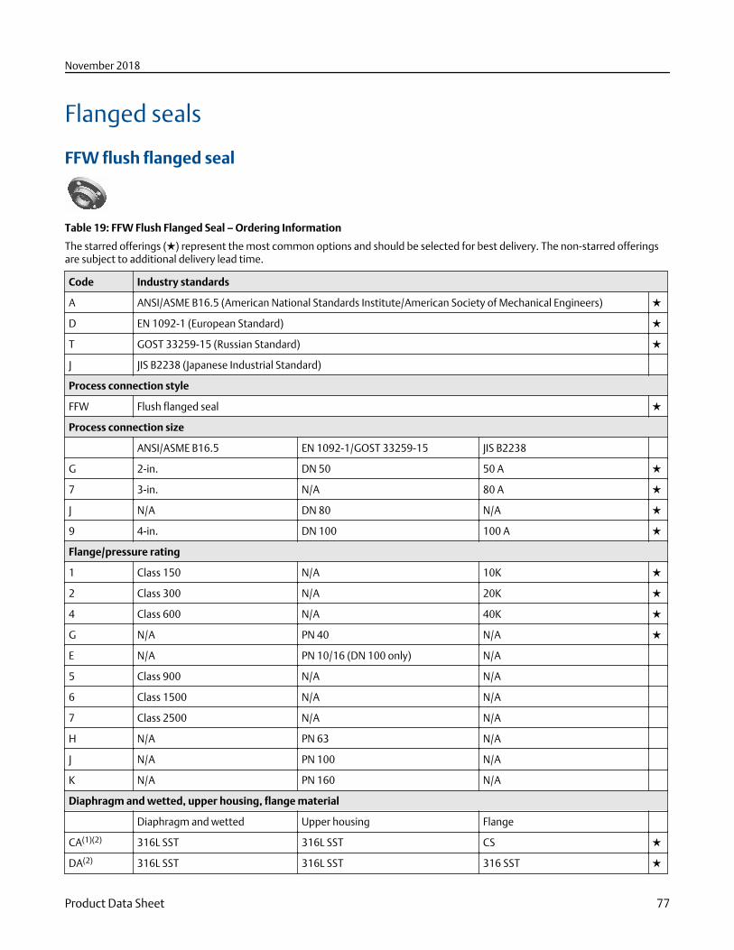
Flanged seals
FFW flush flanged seal
Table 19: FFW Flush Flanged Seal – Ordering Information
The starred offerings (★) represent the most common options and should be selected for best delivery. The non-starred offeringsare subject to additional delivery lead time.
Code Industry standards
A ANSI/ASME B16.5 (American National Standards Institute/American Society of Mechanical Engineers) ★
D EN 1092-1 (European Standard) ★
T GOST 33259-15 (Russian Standard) ★
J JIS B2238 (Japanese Industrial Standard)
Process connection style
FFW Flush flanged seal ★
Process connection size
ANSI/ASME B16.5 EN 1092-1/GOST 33259-15 JIS B2238
G 2-in. DN 50 50 A ★
7 3-in. N/A 80 A ★
J N/A DN 80 N/A ★
9 4-in. DN 100 100 A ★
Flange/pressure rating
1 Class 150 N/A 10K ★
2 Class 300 N/A 20K ★
4 Class 600 N/A 40K ★
G N/A PN 40 N/A ★
E N/A PN 10/16 (DN 100 only) N/A
5 Class 900 N/A N/A
6 Class 1500 N/A N/A
7 Class 2500 N/A N/A
H N/A PN 63 N/A
J N/A PN 100 N/A
K N/A PN 160 N/A
Diaphragm and wetted, upper housing, flange material
Diaphragm and wetted Upper housing Flange
CA(1)(2) 316L SST 316L SST CS ★
DA(2) 316L SST 316L SST 316 SST ★
November 2018
Product Data Sheet 77
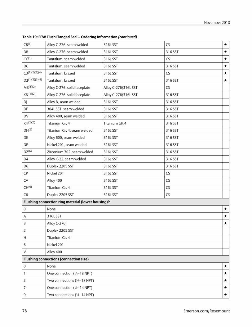
Table 19: FFW Flush Flanged Seal – Ordering Information (continued)
CB(1) Alloy C-276, seam welded 316L SST CS ★
DB Alloy C-276, seam welded 316L SST 316 SST ★
CC(1) Tantalum, seam welded 316L SST CS ★
DC Tantalum, seam welded 316L SST 316 SST ★
C3(1)(2)(3)(4) Tantalum, brazed 316L SST CS ★
D3(1)(2)(3)(4) Tantalum, brazed 316L SST 316 SST ★
MB(1)(2) Alloy C-276, solid faceplate Alloy C-276/316L SST CS
KB (1)(2) Alloy C-276, solid faceplate Alloy C-276/316L SST 316 SST
DJ Alloy B, seam welded 316L SST 316 SST
DF 304L SST, seam welded 316L SST 316 SST
DV Alloy 400, seam welded 316L SST 316 SST
RH(2)(5) Titanium Gr. 4 Titanium GR.4 316 SST
DH(6) Titanium Gr. 4, seam welded 316L SST 316 SST
DE Alloy 600, seam welded 316L SST 316 SST
DP Nickel 201, seam welded 316L SST 316 SST
DZ(6) Zirconium 702, seam welded 316L SST 316 SST
D4 Alloy C-22, seam welded 316L SST 316 SST
D6 Duplex 2205 SST 316L SST 316 SST
CP Nickel 201 316L SST CS
CV Alloy 400 316L SST CS
CH(6) Titanium Gr. 4 316L SST CS
C6 Duplex 2205 SST 316L SST CS
Flushing connection ring material (lower housing)(7)
0 None ★
A 316L SST ★
B Alloy C-276 ★
2 Duplex 2205 SST
H Titanium Gr. 4
6 Nickel 201
V Alloy 400
Flushing connections (connection size)
0 None ★
1 One connection (¼–18 NPT) ★
3 Two connections (¼–18 NPT) ★
7 One connection (½–14 NPT) ★
9 Two connections (½–14 NPT) ★
November 2018
78 Emerson.com/Rosemount
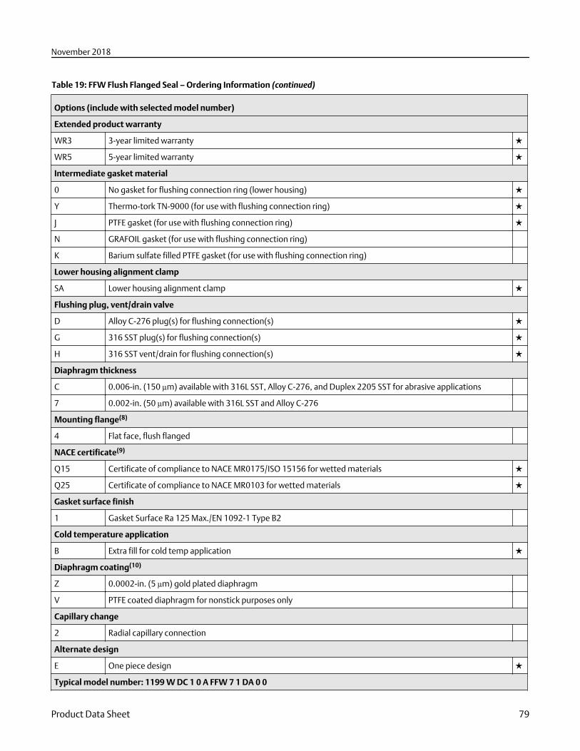
Table 19: FFW Flush Flanged Seal – Ordering Information (continued)
Options (include with selected model number)
Extended product warranty
WR3 3-year limited warranty ★
WR5 5-year limited warranty ★
Intermediate gasket material
0 No gasket for flushing connection ring (lower housing) ★
Y Thermo-tork TN-9000 (for use with flushing connection ring) ★
J PTFE gasket (for use with flushing connection ring) ★
N GRAFOIL gasket (for use with flushing connection ring)
K Barium sulfate filled PTFE gasket (for use with flushing connection ring)
Lower housing alignment clamp
SA Lower housing alignment clamp ★
Flushing plug, vent/drain valve
D Alloy C-276 plug(s) for flushing connection(s) ★
G 316 SST plug(s) for flushing connection(s) ★
H 316 SST vent/drain for flushing connection(s) ★
Diaphragm thickness
C 0.006-in. (150 µm) available with 316L SST, Alloy C-276, and Duplex 2205 SST for abrasive applications
7 0.002-in. (50 µm) available with 316L SST and Alloy C-276
Mounting flange(8)
4 Flat face, flush flanged
NACE certificate(9)
Q15 Certificate of compliance to NACE MR0175/ISO 15156 for wetted materials ★
Q25 Certificate of compliance to NACE MR0103 for wetted materials ★
Gasket surface finish
1 Gasket Surface Ra 125 Max./EN 1092-1 Type B2
Cold temperature application
B Extra fill for cold temp application ★
Diaphragm coating(10)
Z 0.0002-in. (5 µm) gold plated diaphragm
V PTFE coated diaphragm for nonstick purposes only
Capillary change
2 Radial capillary connection
Alternate design
E One piece design ★
Typical model number: 1199 W DC 1 0 A FFW 7 1 DA 0 0
November 2018
Product Data Sheet 79
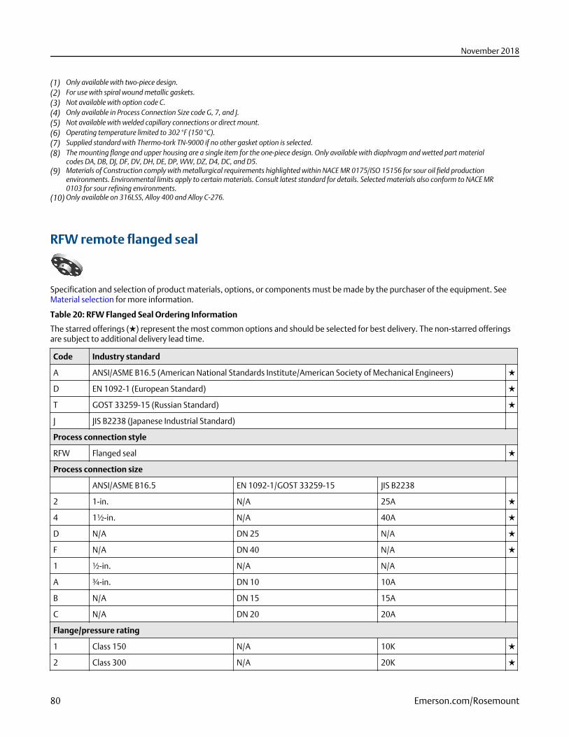
(1) Only available with two-piece design.(2) For use with spiral wound metallic gaskets.(3) Not available with option code C.(4) Only available in Process Connection Size code G, 7, and J.(5) Not available with welded capillary connections or direct mount.(6) Operating temperature limited to 302 °F (150 °C).(7) Supplied standard with Thermo-tork TN-9000 if no other gasket option is selected.(8) The mounting flange and upper housing are a single item for the one-piece design. Only available with diaphragm and wetted part material
codes DA, DB, DJ, DF, DV, DH, DE, DP, WW, DZ, D4, DC, and D5.(9) Materials of Construction comply with metallurgical requirements highlighted within NACE MR 0175/ISO 15156 for sour oil field production
environments. Environmental limits apply to certain materials. Consult latest standard for details. Selected materials also conform to NACE MR0103 for sour refining environments.
(10) Only available on 316LSS, Alloy 400 and Alloy C-276.
RFW remote flanged seal
Specification and selection of product materials, options, or components must be made by the purchaser of the equipment. SeeMaterial selection for more information.
Table 20: RFW Flanged Seal Ordering Information
The starred offerings (★) represent the most common options and should be selected for best delivery. The non-starred offeringsare subject to additional delivery lead time.
Code Industry standard
A ANSI/ASME B16.5 (American National Standards Institute/American Society of Mechanical Engineers) ★
D EN 1092-1 (European Standard) ★
T GOST 33259-15 (Russian Standard) ★
J JIS B2238 (Japanese Industrial Standard)
Process connection style
RFW Flanged seal ★
Process connection size
ANSI/ASME B16.5 EN 1092-1/GOST 33259-15 JIS B2238
2 1-in. N/A 25A ★
4 1½-in. N/A 40A ★
D N/A DN 25 N/A ★
F N/A DN 40 N/A ★
1 ½-in. N/A N/A
A ¾-in. DN 10 10A
B N/A DN 15 15A
C N/A DN 20 20A
Flange/pressure rating
1 Class 150 N/A 10K ★
2 Class 300 N/A 20K ★
November 2018
80 Emerson.com/Rosemount
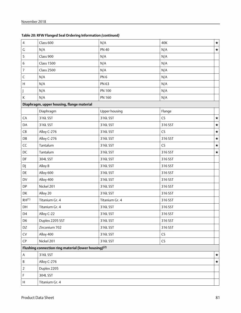
Table 20: RFW Flanged Seal Ordering Information (continued)
4 Class 600 N/A 40K ★
G N/A PN 40 N/A ★
5 Class 900 N/A N/A
6 Class 1500 N/A N/A
7 Class 2500 N/A N/A
C N/A PN 6 N/A
H N/A PN 63 N/A
J N/A PN 100 N/A
K N/A PN 160 N/A
Diaphragm, upper housing, flange material
Diaphragm Upper housing Flange
CA 316L SST 316L SST CS ★
DA 316L SST 316L SST 316 SST ★
CB Alloy C-276 316L SST CS ★
DB Alloy C-276 316L SST 316 SST ★
CC Tantalum 316L SST CS ★
DC Tantalum 316L SST 316 SST ★
DF 304L SST 316L SST 316 SST
DJ Alloy B 316L SST 316 SST
DE Alloy 600 316L SST 316 SST
DV Alloy 400 316L SST 316 SST
DP Nickel 201 316L SST 316 SST
DK Alloy 20 316L SST 316 SST
RH(1) Titanium Gr. 4 Titanium Gr. 4 316 SST
DH Titanium Gr. 4 316L SST 316 SST
D4 Alloy C-22 316L SST 316 SST
D6 Duplex 2205 SST 316L SST 316 SST
DZ Zirconium 702 316L SST 316 SST
CV Alloy 400 316L SST CS
CP Nickel 201 316L SST CS
Flushing connection ring material (lower housing)(2)
A 316L SST ★
B Alloy C-276 ★
2 Duplex 2205
F 304L SST
H Titanium Gr. 4
November 2018
Product Data Sheet 81
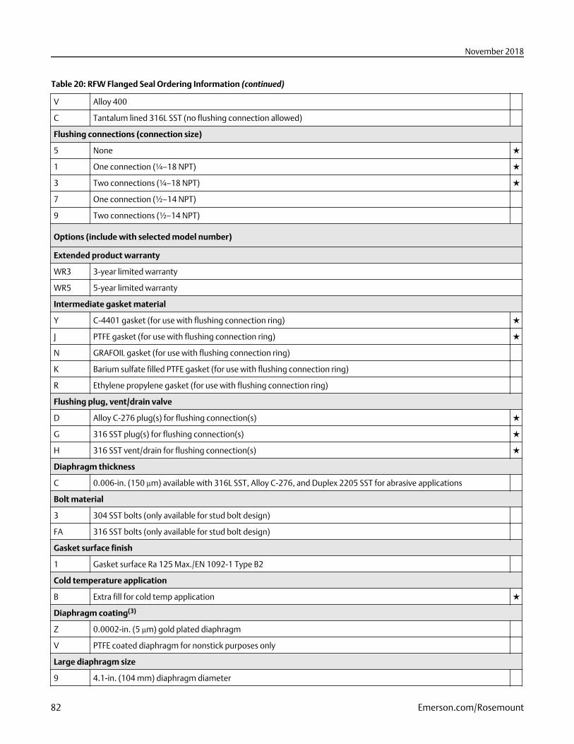
Table 20: RFW Flanged Seal Ordering Information (continued)
V Alloy 400
C Tantalum lined 316L SST (no flushing connection allowed)
Flushing connections (connection size)
5 None ★
1 One connection (¼–18 NPT) ★
3 Two connections (¼–18 NPT) ★
7 One connection (½–14 NPT)
9 Two connections (½–14 NPT)
Options (include with selected model number)
Extended product warranty
WR3 3-year limited warranty
WR5 5-year limited warranty
Intermediate gasket material
Y C-4401 gasket (for use with flushing connection ring) ★
J PTFE gasket (for use with flushing connection ring) ★
N GRAFOIL gasket (for use with flushing connection ring)
K Barium sulfate filled PTFE gasket (for use with flushing connection ring)
R Ethylene propylene gasket (for use with flushing connection ring)
Flushing plug, vent/drain valve
D Alloy C-276 plug(s) for flushing connection(s) ★
G 316 SST plug(s) for flushing connection(s) ★
H 316 SST vent/drain for flushing connection(s) ★
Diaphragm thickness
C 0.006-in. (150 µm) available with 316L SST, Alloy C-276, and Duplex 2205 SST for abrasive applications
Bolt material
3 304 SST bolts (only available for stud bolt design)
FA 316 SST bolts (only available for stud bolt design)
Gasket surface finish
1 Gasket surface Ra 125 Max./EN 1092-1 Type B2
Cold temperature application
B Extra fill for cold temp application ★
Diaphragm coating(3)
Z 0.0002-in. (5 µm) gold plated diaphragm
V PTFE coated diaphragm for nonstick purposes only
Large diaphragm size
9 4.1-in. (104 mm) diaphragm diameter
November 2018
82 Emerson.com/Rosemount
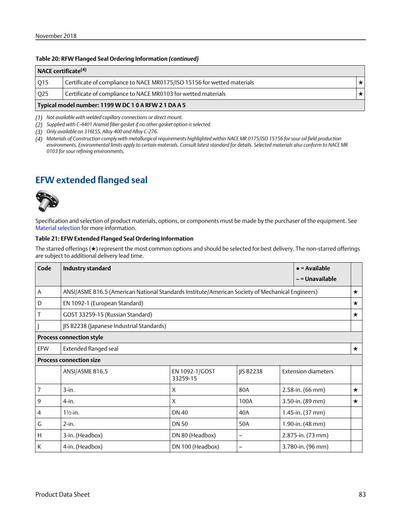
Table 20: RFW Flanged Seal Ordering Information (continued)
NACE certificate(4)
Q15 Certificate of compliance to NACE MR0175/ISO 15156 for wetted materials ★
Q25 Certificate of compliance to NACE MR0103 for wetted materials ★
Typical model number: 1199 W DC 1 0 A RFW 2 1 DA A 5
(1) Not available with welded capillary connections or direct mount.(2) Supplied with C-4401 Aramid fiber gasket if no other gasket option is selected.(3) Only available on 316LSS, Alloy 400 and Alloy C-276.(4) Materials of Construction comply with metallurgical requirements highlighted within NACE MR 0175/ISO 15156 for sour oil field production
environments. Environmental limits apply to certain materials. Consult latest standard for details. Selected materials also conform to NACE MR0103 for sour refining environments.
EFW extended flanged seal
Specification and selection of product materials, options, or components must be made by the purchaser of the equipment. SeeMaterial selection for more information.
Table 21: EFW Extended Flanged Seal Ordering Information
The starred offerings (★) represent the most common options and should be selected for best delivery. The non-starred offeringsare subject to additional delivery lead time.
Code Industry standard ● = Available
– = Unavailable
A ANSI/ASME B16.5 (American National Standards Institute/American Society of Mechanical Engineers) ★
D EN 1092-1 (European Standard) ★
T GOST 33259-15 (Russian Standard) ★
J JIS B2238 (Japanese Industrial Standards)
Process connection style
EFW Extended flanged seal ★
Process connection size
ANSI/ASME B16.5 EN 1092-1/GOST33259-15
JIS B2238 Extension diameters
7 3-in. X 80A 2.58-in. (66 mm) ★
9 4-in. X 100A 3.50-in. (89 mm) ★
4 1½-in. DN 40 40A 1.45-in. (37 mm)
G 2-in. DN 50 50A 1.90-in. (48 mm)
H 3-in. (Headbox) DN 80 (Headbox) – 2.875-in. (73 mm)
K 4-in. (Headbox) DN 100 (Headbox) – 3.780-in. (96 mm)
November 2018
Product Data Sheet 83
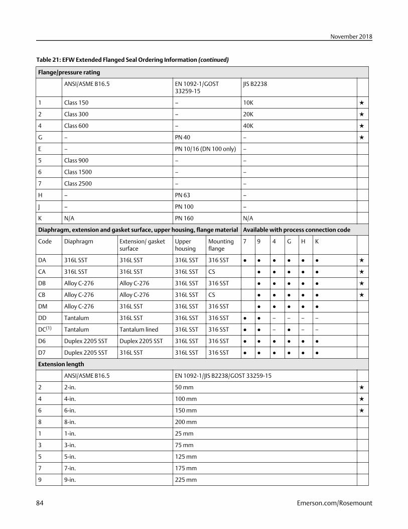
Table 21: EFW Extended Flanged Seal Ordering Information (continued)
Flange/pressure rating
ANSI/ASME B16.5 EN 1092-1/GOST33259-15
JIS B2238
1 Class 150 – 10K ★
2 Class 300 – 20K ★
4 Class 600 – 40K ★
G – PN 40 – ★
E – PN 10/16 (DN 100 only) –
5 Class 900 – –
6 Class 1500 – –
7 Class 2500 – –
H – PN 63 –
J – PN 100 –
K N/A PN 160 N/A
Diaphragm, extension and gasket surface, upper housing, flange material Available with process connection code
Code Diaphragm Extension/ gasketsurface
Upperhousing
Mountingflange
7 9 4 G H K
DA 316L SST 316L SST 316L SST 316 SST ● ● ● ● ● ● ★
CA 316L SST 316L SST 316L SST CS ● ● ● ● ● ★
DB Alloy C-276 Alloy C-276 316L SST 316 SST ● ● ● ● ● ★
CB Alloy C-276 Alloy C-276 316L SST CS ● ● ● ● ● ★
DM Alloy C-276 316L SST 316L SST 316 SST ● ● ● ● ●
DD Tantalum 316L SST 316L SST 316 SST ● ● – – – –
DC(1) Tantalum Tantalum lined 316L SST 316 SST ● ● – ● – –
D6 Duplex 2205 SST Duplex 2205 SST 316L SST 316 SST ● ● ● ● ● ●
D7 Duplex 2205 SST 316L SST 316L SST 316 SST ● ● ● ● ● ●
Extension length
ANSI/ASME B16.5 EN 1092-1/JIS B2238/GOST 33259-15
2 2-in. 50 mm ★
4 4-in. 100 mm ★
6 6-in. 150 mm ★
8 8-in. 200 mm
1 1-in. 25 mm
3 3-in. 75 mm
5 5-in. 125 mm
7 7-in. 175 mm
9 9-in. 225 mm
November 2018
84 Emerson.com/Rosemount
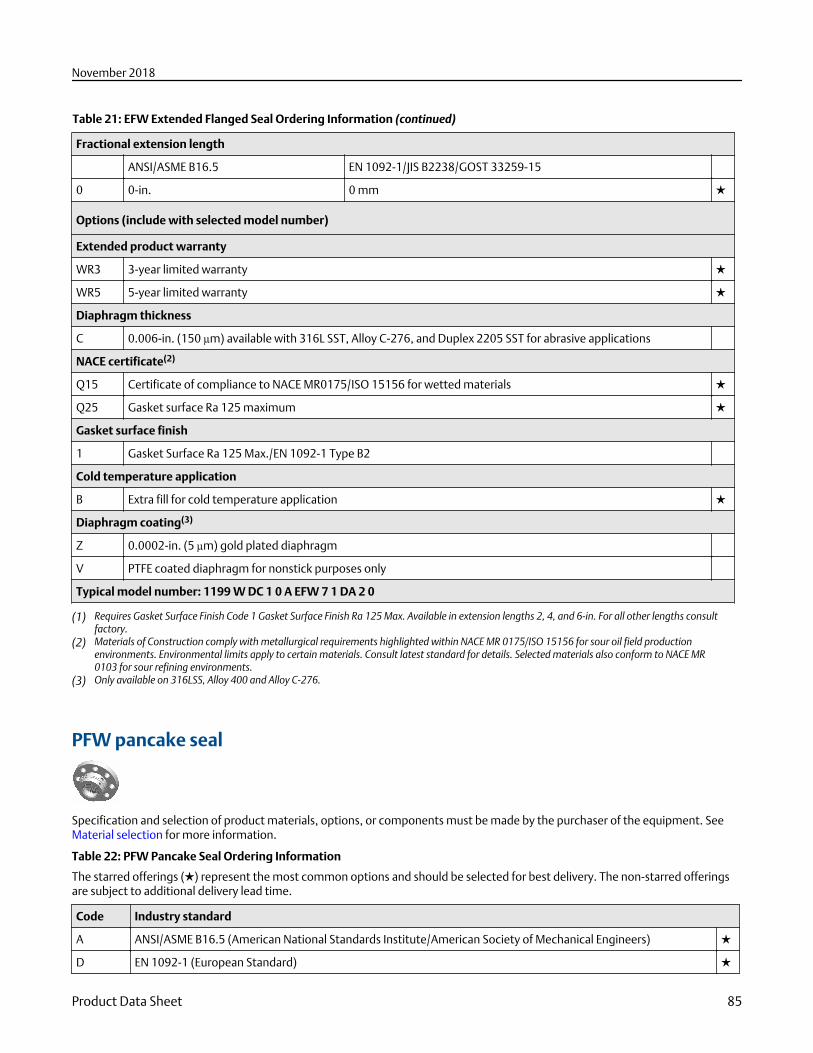
Table 21: EFW Extended Flanged Seal Ordering Information (continued)
Fractional extension length
ANSI/ASME B16.5 EN 1092-1/JIS B2238/GOST 33259-15
0 0-in. 0 mm ★
Options (include with selected model number)
Extended product warranty
WR3 3-year limited warranty ★
WR5 5-year limited warranty ★
Diaphragm thickness
C 0.006-in. (150 µm) available with 316L SST, Alloy C-276, and Duplex 2205 SST for abrasive applications
NACE certificate(2)
Q15 Certificate of compliance to NACE MR0175/ISO 15156 for wetted materials ★
Q25 Gasket surface Ra 125 maximum ★
Gasket surface finish
1 Gasket Surface Ra 125 Max./EN 1092-1 Type B2
Cold temperature application
B Extra fill for cold temperature application ★
Diaphragm coating(3)
Z 0.0002-in. (5 µm) gold plated diaphragm
V PTFE coated diaphragm for nonstick purposes only
Typical model number: 1199 W DC 1 0 A EFW 7 1 DA 2 0
(1) Requires Gasket Surface Finish Code 1 Gasket Surface Finish Ra 125 Max. Available in extension lengths 2, 4, and 6-in. For all other lengths consultfactory.
(2) Materials of Construction comply with metallurgical requirements highlighted within NACE MR 0175/ISO 15156 for sour oil field productionenvironments. Environmental limits apply to certain materials. Consult latest standard for details. Selected materials also conform to NACE MR0103 for sour refining environments.
(3) Only available on 316LSS, Alloy 400 and Alloy C-276.
PFW pancake seal
Specification and selection of product materials, options, or components must be made by the purchaser of the equipment. SeeMaterial selection for more information.
Table 22: PFW Pancake Seal Ordering Information
The starred offerings (★) represent the most common options and should be selected for best delivery. The non-starred offeringsare subject to additional delivery lead time.
Code Industry standard
A ANSI/ASME B16.5 (American National Standards Institute/American Society of Mechanical Engineers) ★
D EN 1092-1 (European Standard) ★
November 2018
Product Data Sheet 85
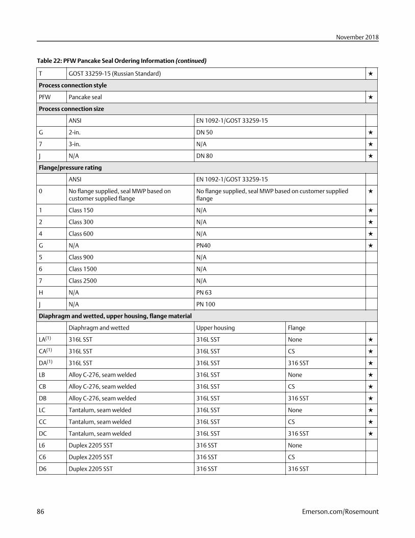
Table 22: PFW Pancake Seal Ordering Information (continued)
T GOST 33259-15 (Russian Standard) ★
Process connection style
PFW Pancake seal ★
Process connection size
ANSI EN 1092-1/GOST 33259-15
G 2-in. DN 50 ★
7 3-in. N/A ★
J N/A DN 80 ★
Flange/pressure rating
ANSI EN 1092-1/GOST 33259-15
0 No flange supplied, seal MWP based oncustomer supplied flange
No flange supplied, seal MWP based on customer suppliedflange
★
1 Class 150 N/A ★
2 Class 300 N/A ★
4 Class 600 N/A ★
G N/A PN40 ★
5 Class 900 N/A
6 Class 1500 N/A
7 Class 2500 N/A
H N/A PN 63
J N/A PN 100
Diaphragm and wetted, upper housing, flange material
Diaphragm and wetted Upper housing Flange
LA(1) 316L SST 316L SST None ★
CA(1) 316L SST 316L SST CS ★
DA(1) 316L SST 316L SST 316 SST ★
LB Alloy C-276, seam welded 316L SST None ★
CB Alloy C-276, seam welded 316L SST CS ★
DB Alloy C-276, seam welded 316L SST 316 SST ★
LC Tantalum, seam welded 316L SST None ★
CC Tantalum, seam welded 316L SST CS ★
DC Tantalum, seam welded 316L SST 316 SST ★
L6 Duplex 2205 SST 316 SST None
C6 Duplex 2205 SST 316 SST CS
D6 Duplex 2205 SST 316 SST 316 SST
November 2018
86 Emerson.com/Rosemount
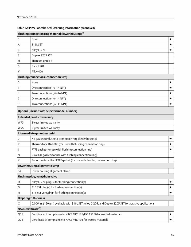
Table 22: PFW Pancake Seal Ordering Information (continued)
Flushing connection ring material (lower housing)(2)
0 None ★
A 316L SST ★
B Alloy C-276 ★
2 Duplex 2205 SST
H Titanium grade 4
6 Nickel 201
V Alloy 400
Flushing connections (connection size)
0 None ★
1 One connection (¼–14 NPT) ★
3 Two connections (¼–14 NPT) ★
7 One connection (½–14 NPT) ★
9 Two connections (½–14 NPT) ★
Options (include with selected model number)
Extended product warranty
WR3 3-year limited warranty
WR5 5-year limited warranty
Intermediate gasket material
0 No gasket for flushing connection ring (lower housing) ★
Y Thermo-tork TN-9000 (for use with flushing connection ring) ★
J PTFE gasket (for use with flushing connection ring) ★
N GRAFOIL gasket (for use with flushing connection ring)
K Barium sulfate filled PTFE gasket (for use with flushing connection ring)
Lower housing alignment clamp
SA Lower housing alignment clamp
Flushing plug, vent/drain valve
D Alloy C-276 plug(s) for flushing connection(s) ★
G 316 SST plug(s) for flushing connection(s) ★
H 316 SST vent/drain for flushing connection(s) ★
Diaphragm thickness
C 0.006-in. (150 µm) available with 316L SST, Alloy C-276, and Duplex 2205 SST for abrasive applications
NACE certificate(3)
Q15 Certificate of compliance to NACE MR0175/ISO 15156 for wetted materials ★
Q25 Certificate of compliance to NACE MR0103 for wetted materials ★
November 2018
Product Data Sheet 87
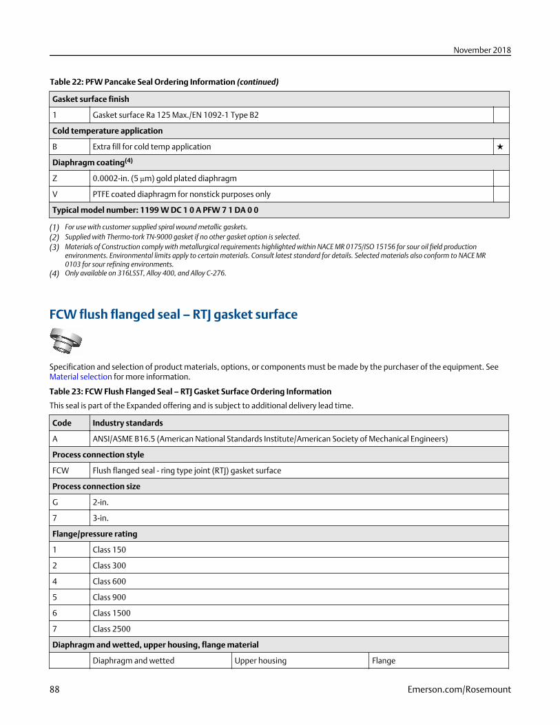
Table 22: PFW Pancake Seal Ordering Information (continued)
Gasket surface finish
1 Gasket surface Ra 125 Max./EN 1092-1 Type B2
Cold temperature application
B Extra fill for cold temp application ★
Diaphragm coating(4)
Z 0.0002-in. (5 µm) gold plated diaphragm
V PTFE coated diaphragm for nonstick purposes only
Typical model number: 1199 W DC 1 0 A PFW 7 1 DA 0 0
(1) For use with customer supplied spiral wound metallic gaskets.(2) Supplied with Thermo-tork TN-9000 gasket if no other gasket option is selected.(3) Materials of Construction comply with metallurgical requirements highlighted within NACE MR 0175/ISO 15156 for sour oil field production
environments. Environmental limits apply to certain materials. Consult latest standard for details. Selected materials also conform to NACE MR0103 for sour refining environments.
(4) Only available on 316LSST, Alloy 400, and Alloy C-276.
FCW flush flanged seal – RTJ gasket surface
Specification and selection of product materials, options, or components must be made by the purchaser of the equipment. SeeMaterial selection for more information.
Table 23: FCW Flush Flanged Seal – RTJ Gasket Surface Ordering Information
This seal is part of the Expanded offering and is subject to additional delivery lead time.
Code Industry standards
A ANSI/ASME B16.5 (American National Standards Institute/American Society of Mechanical Engineers)
Process connection style
FCW Flush flanged seal - ring type joint (RTJ) gasket surface
Process connection size
G 2-in.
7 3-in.
Flange/pressure rating
1 Class 150
2 Class 300
4 Class 600
5 Class 900
6 Class 1500
7 Class 2500
Diaphragm and wetted, upper housing, flange material
Diaphragm and wetted Upper housing Flange
November 2018
88 Emerson.com/Rosemount
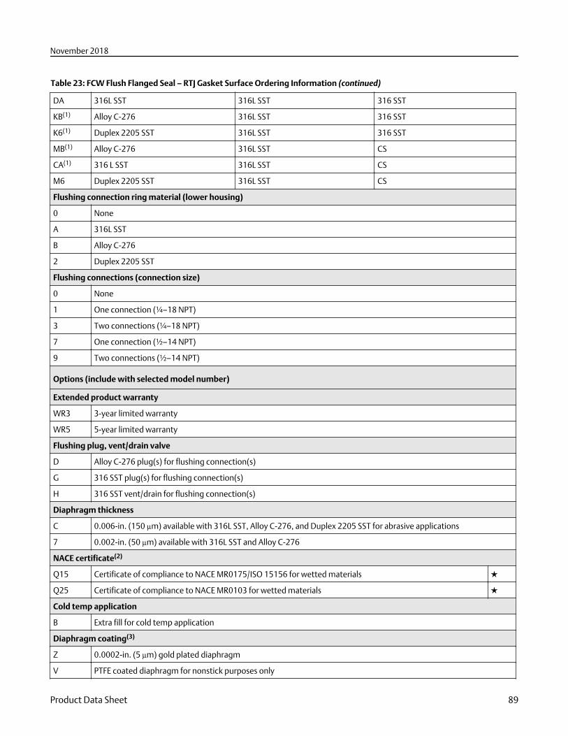
Table 23: FCW Flush Flanged Seal – RTJ Gasket Surface Ordering Information (continued)
DA 316L SST 316L SST 316 SST
KB(1) Alloy C-276 316L SST 316 SST
K6(1) Duplex 2205 SST 316L SST 316 SST
MB(1) Alloy C-276 316L SST CS
CA(1) 316 L SST 316L SST CS
M6 Duplex 2205 SST 316L SST CS
Flushing connection ring material (lower housing)
0 None
A 316L SST
B Alloy C-276
2 Duplex 2205 SST
Flushing connections (connection size)
0 None
1 One connection (¼–18 NPT)
3 Two connections (¼–18 NPT)
7 One connection (½–14 NPT)
9 Two connections (½–14 NPT)
Options (include with selected model number)
Extended product warranty
WR3 3-year limited warranty
WR5 5-year limited warranty
Flushing plug, vent/drain valve
D Alloy C-276 plug(s) for flushing connection(s)
G 316 SST plug(s) for flushing connection(s)
H 316 SST vent/drain for flushing connection(s)
Diaphragm thickness
C 0.006-in. (150 µm) available with 316L SST, Alloy C-276, and Duplex 2205 SST for abrasive applications
7 0.002-in. (50 µm) available with 316L SST and Alloy C-276
NACE certificate(2)
Q15 Certificate of compliance to NACE MR0175/ISO 15156 for wetted materials ★
Q25 Certificate of compliance to NACE MR0103 for wetted materials ★
Cold temp application
B Extra fill for cold temp application
Diaphragm coating(3)
Z 0.0002-in. (5 µm) gold plated diaphragm
V PTFE coated diaphragm for nonstick purposes only
November 2018
Product Data Sheet 89
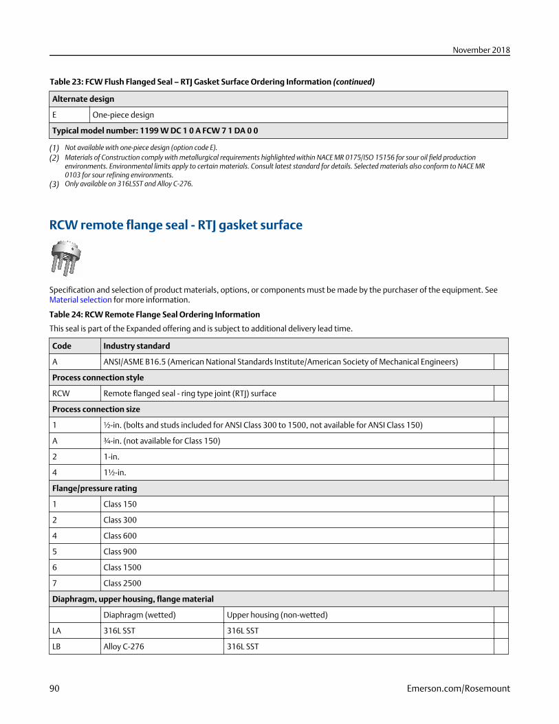
Table 23: FCW Flush Flanged Seal – RTJ Gasket Surface Ordering Information (continued)
Alternate design
E One-piece design
Typical model number: 1199 W DC 1 0 A FCW 7 1 DA 0 0
(1) Not available with one-piece design (option code E).(2) Materials of Construction comply with metallurgical requirements highlighted within NACE MR 0175/ISO 15156 for sour oil field production
environments. Environmental limits apply to certain materials. Consult latest standard for details. Selected materials also conform to NACE MR0103 for sour refining environments.
(3) Only available on 316LSST and Alloy C-276.
RCW remote flange seal - RTJ gasket surface
Specification and selection of product materials, options, or components must be made by the purchaser of the equipment. SeeMaterial selection for more information.
Table 24: RCW Remote Flange Seal Ordering Information
This seal is part of the Expanded offering and is subject to additional delivery lead time.
Code Industry standard
A ANSI/ASME B16.5 (American National Standards Institute/American Society of Mechanical Engineers)
Process connection style
RCW Remote flanged seal - ring type joint (RTJ) surface
Process connection size
1 ½-in. (bolts and studs included for ANSI Class 300 to 1500, not available for ANSI Class 150)
A ¾-in. (not available for Class 150)
2 1-in.
4 1½-in.
Flange/pressure rating
1 Class 150
2 Class 300
4 Class 600
5 Class 900
6 Class 1500
7 Class 2500
Diaphragm, upper housing, flange material
Diaphragm (wetted) Upper housing (non-wetted)
LA 316L SST 316L SST
LB Alloy C-276 316L SST
November 2018
90 Emerson.com/Rosemount
Table 24: RCW Remote Flange Seal Ordering Information (continued)
LC Tantalum 316L SST
LE Alloy 600 316L SST
LF 304L SST 316L SST
LJ Alloy B 316L SST 316L SST
LV Alloy 400 316L SST
LP Nickel 201 316L SST
BH Titanium Gr. 4 Titanium Gr. 4
LH(1) Titanium Gr. 4 316L SST
L4 Alloy 22 316L SST
L6 Duplex 2205 SST 316L SST
LZ(1) Zirconium 702 316L SST
LK Alloy 20 316L SST
Flushing connection ring material (lower housing)(2)
A 316L SST
B Alloy C-276
F 304L SST
H Titanium Gr. 4
2 Duplex 2205 SST
V Alloy 400
Flushing connections (connection size)
5 None
1 One connection (¼–18 NPT)
3 Two connections (¼–18 NPT)
7 One connection (½–14 NPT)
9 Two connections (½–14 NPT)
Options (include with selected model number)
Extended product warranty
WR3 3-year limited warranty
WR5 5-year limited warranty
Intermediate gasket material
Y C-4401 gasket (for use with flushing connection ring) ★
J PTFE gasket (for use with flushing connection ring)
N GRAFOIL gasket (for use with flushing connection ring)
K Barium sulfate filled PTFE gasket (for use with flushing connection ring)
R Ethylene propylene gasket (for use with flushing connection ring)
November 2018
Product Data Sheet 91
Table 24: RCW Remote Flange Seal Ordering Information (continued)
Flushing plug, vent/drain valve
D Alloy C-276 plug(s) for flushing connection(s)
G 316 SST plug(s) for flushing connection(s)
H 316 SST vent/drain for flushing connection(s)
Diaphragm thickness
C 0.006-in. (150 Xm) available with 316L SST, Alloy C-276, and Duplex 2205 SST for abrasive applications
Bolt material (optional)
3 304 SST bolts (only available for stud bolt design)
FA 316 SST bolts (only available for stud bolt design)
NACE certificate(3)
Q15 Certificate of compliance to NACE MR0175/ISO 15156 for wetted materials
Q25 Certificate of compliance to NACE MR0103 for wetted materials
Cold temperature application
B Extra fill for cold temp application
Diaphragm coating
Z(4) 0.0002-in. (5 µm) gold plated diaphragm
V(3) PTFE coated diaphragm for nonstick purposes only
Large diaphragm size
9 4.1-in. (104 mm) diaphragm diameter
Typical model number: 1199 W DC 1 0 A RCW 2 1 LA A 5
(1) Operating temperature is limited to 302 °F (150 °C).(2) Supplied with C-4401 aramid fiber gasket if no other gasket option is selected.(3) Materials of Construction comply with metallurgical requirements highlighted within NACE MR 0175/ISO 15156 for sour oil field production
environments. Environmental limits apply to certain materials. Consult latest standard for details. Selected materials also conform to NACE MR0103 for sour refining environments.
(4) Only available on 316LSS, Alloy 400, and Alloy C-276.
FUW and FVW flush flanged type seals
Specification and selection of product materials, options, or components must be made by the purchaser of the equipment. SeeMaterial selection for more information.
Table 25: FUW and FVW Flush Flanged Type Seals – EN Ordering Information
This seal is part of the Expanded offering is subject to additional delivery lead time.
Code Industry standard
D EN 1092-1 (European Standard)
T GOST 33259-15 (Russian Standard)
November 2018
92 Emerson.com/Rosemount
Table 25: FUW and FVW Flush Flanged Type Seals – EN Ordering Information (continued)
Process connection style
FUW Flush flanged, EN 1092-1 type D (groove)
FVW Flush flanged, EN 1092-1 type C (tongue)
Process connection size
G DN 50
J DN 80
Flange/pressure rating
G PN 40
Diaphragm and wetted, upper housing, flange material
Diaphragm (wetted) Upper housing (non-wetted) Flange
DA(1) 316L SST 316L SST 316 SST
KB(2) Alloy C-276 316L SST 316 SST
DC(1) Tantalum 316L SST 316 SST
Flushing connection ring material (lower housing)
0 None
Flushing connection options, quantity (size)
0 None
Options (include with selected model number)
Extended product warranty
WR3 3-year limited warranty
WR5 5-year limited warranty
Cold temperature application
B Extra fill for cold temperature application
Alternate design
E One piece design
NACE certificate(3)
Q15 Certificate of compliance to NACE MR0175/ISO 15156 for wetted materials ★
Q25 Certificate of compliance to NACE MR0103 for wetted materials ★
Typical model number: 1199 W DC 1 0 A FUW J G DA 0 0
(1) Only available with one-piece design, option code E.(2) Only available with two-piece design.(3) Materials of Construction comply with metallurgical requirements highlighted within NACE MR 0175/ISO 15156 for sour oil field production
environments. Environmental limits apply to certain materials. Consult latest standard for details. Selected materials also conform to NACE MR0103 for sour refining environments.
November 2018
Product Data Sheet 93
Threaded seals
RTW remote threaded seal
Specification and selection of product materials, options, or components must be made by the purchaser of the equipment. SeeMaterial selection for more information.
Table 26: RTW Remote Threaded Seal Ordering Information
The starred offerings (★) represent the most common options and should be selected for best delivery. The non-starred offeringsare subject to additional delivery lead time.
Code Industry standard
A ANSI/ASME B1.20.1 (American National Standards Institute/American Society of Mechanical Engineers) ★
D EN 10226-1 / ISO 228-1 ★
Process connection style
RTW Threaded (standard thread is female, for male select Option code 9) ★
Process connection size
ANSI/ASME B1.20.1 EN 10226-1 ISO 228-1
3 ½–14 NPT N/A N/A ★
4 ¾–14 NPT N/A N/A ★
5 1–11½ NPT N/A N/A ★
7(1) 1½–11½ NPT N/A N/A ★
1 ¼–18 NPT N/A N/A
C N/A N/A G½ (EN 837-1)
2 ⅜–18 NPT N/A N/A
6(1) 1¼–11½ NPT N/A N/A
N N/A Tapered thread: R½ per ISO 7/1 N/A
Pressure rating
ANSI/ASME B1.20.1 EN 10226-1 ISO 228-1
0 2500 psi 172 bar H 172 bar H ★
2(2) 5000 psi 344 bar 344 bar
3(2)(3) 10000 psi N/A N/A
8 1500 psi (4.1-in. [104 mm]) diaphragm 103 bar (4.1-in. [104 mm])diaphragm
103 bar (4.1-in. [104 mm])diaphragm
Diaphragm, upper housing, flange material
Diaphragm (wetted) Upper housing (non-wetted) Flange
CA 316L SST 316L SST CS ★
DA 316L SST 316L SST 316 SST ★
November 2018
94 Emerson.com/Rosemount
Table 26: RTW Remote Threaded Seal Ordering Information (continued)
CB Alloy C-276 316L SST CS ★
DB Alloy C-276 316L SST 316 SST ★
CC Tantalum 316L SST CS ★
DC Tantalum 316L SST 316 SST ★
DJ Alloy B 316L SST 316 SST
DF 304L SST 316L SST 316 SST
DP Nickel 201 316L SST 316 SST
DV Alloy 400 316L SST 316 SST
RH(4) Titanium Gr. 4 Titanium Gr. 4 316 SST
DH(5) Titanium Gr. 4 316L SST 316 SST
D4 Alloy 22 316L SST 316 SST
D6 Duplex 2205 SST 316L SST 316 SST
DE Alloy 600 316L SST 316 SST
DZ(5) Zirconium 702 316L SST 316 SST
DK Alloy 20 316L SST 316 SST
RZ(4) Zirconium 702 Zirconium 702 316 SST
Flushing connection ring material (lower housing)(6)(7)
A 316L SST ★
B Alloy C-276 ★
D Plated carbon steel
2 Duplex 2205 SST
H Titanium Gr. 4
V Alloy 400
F 304L SST
Flushing connections (connection size)
5 None ★
1 One connection (¼–18 NPT) ★
3 Two connections (¼–18 NPT) ★
7 One connection (½–14 NPT)
9 Two connections (½–14 NPT)
Options (include with selected model number)
Extended product warranty
WR3 3-year limited warranty
WR5 5-year limited warranty
Intermediate gasket material
Y C-4401 gasket (for use with flushing connection ring) ★
November 2018
Product Data Sheet 95
Table 26: RTW Remote Threaded Seal Ordering Information (continued)
J PTFE gasket (for use with flushing connection ring) ★
N GRAFOIL gasket (for use with flushing connection ring) ★
R Ethylene propylene gasket (for use with flushing connection ring) ★
K Barium sulfate filled PTFE gasket (for use with flushing connection ring)
Flushing plug, vent/drain valve
D Alloy C-276 plug(s) for flushing connection(s) ★
G 316 SST plug(s) for flushing connection(s) ★
H 316 SST vent/drain for flushing connection(s) ★
Diaphragm thickness
C 0.006-in. (150 µm) available with 316L SST, Alloy C-276, and Duplex 2205 SST for abrasive applications
Bolt material
3 304 SST bolts ★
4 316 SST bolts
NACE certificate(8)
Q15 Certificate of compliance to NACE MR0175/ISO 15156 for wetted materials ★
Q25 Certificate of compliance to NACE MR0103 for wetted materials ★
Cold temperature application
B Extra fill for cold temp application ★
Diaphragm coating(9)
Z 0.0002-in. (5 µm) gold plated diaphragm
V PTFE coated diaphragm for nonstick purposes only
Special threads in lower housing
9 Male threads
Typical model number: 1199 W DC 1 0 A RTW 3 0 DA A 5
(1) Flushing connection not available.(2) Consult an Emerson representative for pricing and availability on Pressure Rating codes 2 or 3.(3) The following process connection sizes are derated: ¾-in. (9000 psi/621 bar), 1-in. (8700 psi/600 bar), 1¼-in. (7000 psi/483 bar), and 1½-in.
(6000 psi/414 bar).(4) Not available with welded capillary connections or direct mount.(5) Operating temperature is limited to 302 °F (150 °C).(6) Supplied with C-4401 aramid fiber gasket if no other gasket option is selected.(7) Flushing Connection Ring/Lower Housing assembly bolts provided as standard are carbon steel for ANSI and 304 SST for EN.(8) Materials of Construction comply with metallurgical requirements highlighted within NACE MR 0175/ISO 15156 for sour oil field production
environments. Environmental limits apply to certain materials. Consult latest standard for details. Selected materials also conform to NACE MR0103 for sour refining environments.
(9) Only available on 316LSS, Alloy 400, and Alloy C-276.
November 2018
96 Emerson.com/Rosemount
HTS male threaded seal
Specification and selection of product materials, options, or components must be made by the purchaser of the equipment. SeeMaterial selection for more information.
Table 27: HTS Male Threaded Seal Ordering Information
This seal is part of the Expanded offering and is subject to additional delivery lead time.
Code Industry standard
A ANSI/ASME B1.20.1 (American National Standards Institute/American Society of Mechanical Engineers)
D ISO 228-1
Process connection style
HTS Threaded - male threaded seal
Process connection size, pressure rating
ANSI/ASME B1.20.1 ISO 228-1
5A(1) 1–11½ NPT, 8700 psi (600 bar) N/A
7A(2) 1½–11½ NPT, 6000 psi (414 bar) N/A
9A(3) 2–11½ NPT, 4000 psi (276 bar) N/A
EA(1) N/A G1 (ISO 1179-3)
GA(2) N/A G1½ (ISO 1179-3)
JA(3) N/A G2 (ISO 1179-3)
Diaphragm and wetted, upper housing material
Diaphragm (wetted) Upper housing (non-wetted)
LA00 316L SST 316L SST
Options (include with selected model number)
Extended product warranty
WR3 3-year limited warranty
WR5 5-year limited warranty
Typical model number: 1199 W DC 1 0 A HTS 7 A LA 0 0
(1) Consult factory for calibrated spans lower than 300 psi (21 bar).(2) Consult factory for calibrated spans lower than 100 psi (7 bar).(3) Consult factory for calibrated spans lower than 50 psi (3.4 bar).
November 2018
Product Data Sheet 97
Hygienic seals
SCW hygienic Tri-Clover style Tri-Clamp seal
Specification and selection of product materials, options, or components must be made by the purchaser of the equipment. SeeMaterial selection for more information.
Table 28: SCW Hygienic Tri-Clover Style Tri-Clamp Seal Ordering Information
The starred offerings (★) represent the most common options and should be selected for best delivery. The non-starred offeringsare subject to additional delivery lead time.
Industry standard
S Hygienic seal (conforms to 3-A Standard 74-06 and EHEDG Type EL Class I) ★
Process connection style
SCW(1)(2) Tri-Clover style Tri-Clamp seal ★
Process connection size
30(3) 1½-in. ★
50(4) 2-in. ★
70 3-in. ★
60 2½-in.
90 4-in.
Diaphragm and wetted, upper housing material
Diaphragm (wetted) Upper housing (non-wetted)
LA00 316L SST 316L SST ★
LB00 Alloy C-276 316L SST
Options (include with selected model number)
Extended product warranty
WR3 3-year limited warranty
WR5 5-year limited warranty
Surface finish
D 10 µin. (0.25 µm) Ra surface finish
G 15 µin. (0.375 µm) Ra surface finish
H 20 µin. (0.50 µm) Ra surface finish
Non-hygienic fill fluid
P Non-hygienic fill fluid (does not conform to 3-A Standard 74)
Clamp and gasket material(5)
2(6) High-Pressure Ladish™ Clamp and Nitrile Butadiene (NBR) Gasket
3 Nitrile Butadiene (NBR) gasket
November 2018
98 Emerson.com/Rosemount
Table 28: SCW Hygienic Tri-Clover Style Tri-Clamp Seal Ordering Information (continued)
Polishing
6 Electropolishing
Typical model number: 1199 W NC 1 0 S SCW 7 0 LA 0 0
(1) For gaskets furnished by the user, ensure EGEDG-approved gaskets are used to ensure conformity. EHEDG conformity is not retained if clamp andgasket material codes 2 or 3 are selected.
(2) All process wetted parts have surface finish of Ra < 32 μin (0.81 μm) standard unless otherwise specified.(3) Consult factory for calibrated spans lower than 1000 inH2O (2490 mbar).(4) Consult factory for calibrated spans lower than 150 inH2O (373 mbar).(5) Not EHEDG approved.(6) See Table 29.
Table 29: High Pressure Ladish Clamp MWP
Process connection size 70 °F (21 °C) 250 °F (121 °C)
1½-in. 1,500 psi (103 bar) 1,200 psi (83 bar)
2-in. 1,000 psi (69 bar) 800 psi (55 bar)
2½-in. 1,000 psi (69 bar) 800 psi (55 bar)
3-in. 1,000 psi (69 bar) 800 psi (55 bar)
4-in. 1,000 psi (69 bar) 800 psi (55 bar)
SSW hygienic tank spud seal
Specification and selection of product materials, options, or components must be made by the purchaser of the equipment. SeeMaterial selection for more information.
Table 30: SSW Hygienic Tank Spud Seal Ordering Information
The starred offerings (★) represent the most common options and should be selected for best delivery. The non-starred offeringsare subject to additional delivery lead time.
Code Industry standard
S Hygienic seal (conforms to 3-A Standard 74-06) ★
Process connection style
SSW(1)(
2)Tank spud seal ★
Process connection size, pressure rating
A0 150 psi (10.3 bar) ★
Upper housing
A 316L SST ★
Diaphragm and wetted, extension material
Diaphragm and wetted Extension
November 2018
Product Data Sheet 99
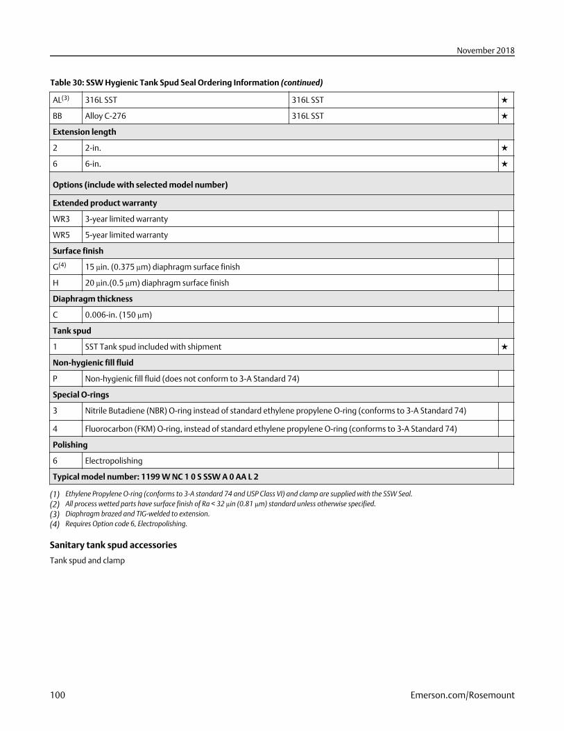
Table 30: SSW Hygienic Tank Spud Seal Ordering Information (continued)
AL(3) 316L SST 316L SST ★
BB Alloy C-276 316L SST ★
Extension length
2 2-in. ★
6 6-in. ★
Options (include with selected model number)
Extended product warranty
WR3 3-year limited warranty
WR5 5-year limited warranty
Surface finish
G(4) 15 µin. (0.375 µm) diaphragm surface finish
H 20 µin.(0.5 µm) diaphragm surface finish
Diaphragm thickness
C 0.006-in. (150 µm)
Tank spud
1 SST Tank spud included with shipment ★
Non-hygienic fill fluid
P Non-hygienic fill fluid (does not conform to 3-A Standard 74)
Special O-rings
3 Nitrile Butadiene (NBR) O-ring instead of standard ethylene propylene O-ring (conforms to 3-A Standard 74)
4 Fluorocarbon (FKM) O-ring, instead of standard ethylene propylene O-ring (conforms to 3-A Standard 74)
Polishing
6 Electropolishing
Typical model number: 1199 W NC 1 0 S SSW A 0 AA L 2
(1) Ethylene Propylene O-ring (conforms to 3-A standard 74 and USP Class VI) and clamp are supplied with the SSW Seal.(2) All process wetted parts have surface finish of Ra < 32 μin (0.81 μm) standard unless otherwise specified.(3) Diaphragm brazed and TIG-welded to extension.(4) Requires Option code 6, Electropolishing.
Sanitary tank spud accessories
Tank spud and clamp
November 2018
100 Emerson.com/Rosemount
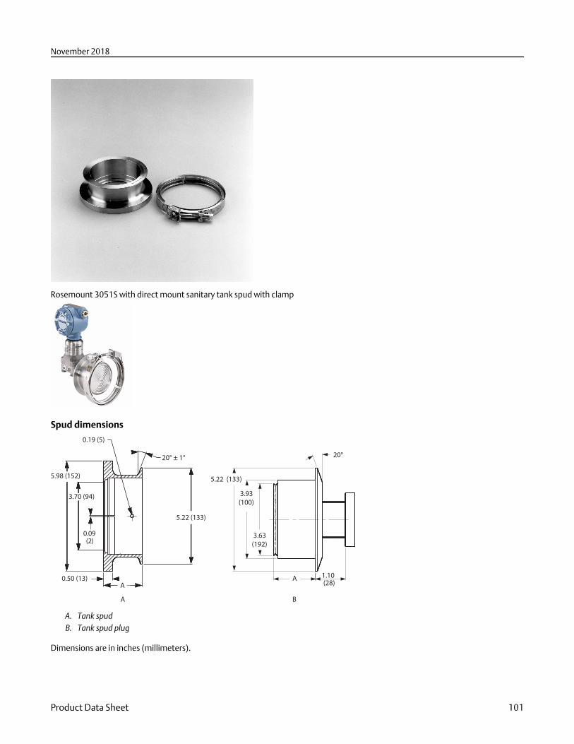
Rosemount 3051S with direct mount sanitary tank spud with clamp
Spud dimensions
20° ± 1°
0.19 (5)
5.22 (133)
5.98 (152)
3.70 (94)
0.09
(2)
0.50 (13)A
A
20°
5.22 (133)
3.93
(100)
3.63
(192)
A1.10
(28)
B
A. Tank spudB. Tank spud plug
Dimensions are in inches (millimeters).
November 2018
Product Data Sheet 101
Table 31: Sanitary Tank Spud Optional Accessories
Welding procedures and material certifications are shipped with the tank spud. Standard material is cast equivalent of 316L SST perASTM- A351 grade CF3M.
Model Description
01199-0061-0001 2-in. SST sanitary tank spud
01199-0061-0002 6-in. SST sanitary tank spud
Table 32: Sanitary Tank Spud Spare Parts
Part number Description
01199-0526-0002 Clamp
C53185-0070-0341 Ethylene propylene O-ring
STW hygienic thin wall tank spud seal
Specification and selection of product materials, options, or components must be made by the purchaser of the equipment. SeeMaterial selection for more information.
Table 33: STW Hygienic Thin Wall Tank Spud Seal Ordering Information
This seal is part of the Expanded offering and is subject to additional delivery lead time.
Code Industry standard
S Hygienic seal (conforms to 3-A® Standard 74-06)
Process connection style(1)
STW(2) Thin wall tank spud seal
Process connection size, pressure rating
B0 4-in. Tri Clamp, 150 psi (41 bar)
Diaphragm and wetted, extension material
Diaphragm and wetted Extension
LA00 316L SST 316L SST
BB00 Alloy C-276 Alloy C-276
Options (include with selected model number)
Extended product warranty
WR3 3-year limited warranty
WR5 5-year limited warranty
Surface finish
G(3) 15 µin. (0.375 µm) diaphragm surface finish
H 20 µin.(0.5 µm) diaphragm surface finish
November 2018
102 Emerson.com/Rosemount
Table 33: STW Hygienic Thin Wall Tank Spud Seal Ordering Information (continued)
Non-hygienic fill fluid
P Non-hygienic fill fluid (does not conform to 3-A Standard 74)
Polishing
6 Electropolishing
Typical model number: 1199 W NC 1 0 S STW B 0 LA 0 0
(1) For tank walls up to 3/16-in. thick. Ethylene Propylene O-ring (conforms to 3-A standard 74 and USP Class VI) and clamp are supplied with theSTW Seal.
(2) All process wetted parts have surface finish of Ra < 32 μin (0.81 μm) standard unless otherwise specified.(3) Requires Option code 6, Electropolishing.
EES hygienic flanged tank spud extended seal
Specification and selection of product materials, options, or components must be made by the purchaser of the equipment. SeeMaterial selection for more information.
Table 34: EES Hygienic Flanged Tank Spud Extended Seal Ordering Information
This seal is part of the Expanded offering and is subject to additional delivery lead time.
Code Industry standard
S Hygienic seal (conforms to 3-A® Standard 74-06)
Process connection style
EES(1) Flanged tank spud seal
Process connection size, pressure rating
GG DN 50, PN 40
JG DN 80, PN 40
Diaphragm and wetted, extension material
Diaphragm and wetted Extension
LA 316L SST 316L SST
LB Alloy C-276 316L SST
Extension length(2)
10 25 mm (1-in.)
Options (include with selected model number)
Extended product warranty
WR3 3-year limited warranty
WR5 5-year limited warranty
Surface finish
G(3) 15 µin. (0.375 µm) Ra surface finish
H 20 µin. (0.50 µm) Ra surface finish
November 2018
Product Data Sheet 103
Table 34: EES Hygienic Flanged Tank Spud Extended Seal Ordering Information (continued)
Gasket material
1 Fluorocarbon (FMK) O-ring, instead of Standard Ethylene Propylene O-ring (conforms to 3-A Standard 74).
Non-hygienic fill fluids
P Non-hygienic fill fluid (does not conform to 3-a standard 74)
Cold temperature application
B Extra fill for cold temperature application
Polishing
6 Electropolishing
Typical model number: 1199 W NC 1 0 S EES J G LA 1 0
(1) All process wetted parts have surface finish of Ra < 32 μin (0.81 μm) standard unless otherwise specified.(2) Other extension lengths are available upon request.(3) Requires Option code 6, Electropolishing.
VCS Tri-Clamp in-line seal
Specification and selection of product materials, options, or components must be made by the purchaser of the equipment. SeeMaterial selection for more information.
Table 35: VCS Tri-Clamp In-Line Seal Ordering Information
This seal is part of the Expanded offering and is subject to additional delivery lead time.
Code Industry standard
S Hygienic seal (conforms to 3-A Standard 74-06 and EHEDG Type EL Class I)
Process connection style
VCS(1)(2) In-line Tri-Clover style Tri-Clamp seal
Process connection size
20(3) 1-in.
30(4) 1½-in.
50 2-in.
70 3-in.
90 4-in.
Diaphragm and wetted, upper housing material
Diaphragm (wetted) Upper housing (non-wetted)
LA00 316L SST 316L SST
Options (include with selected model number)
Extended product warranty
WR3 3-year limited warranty
November 2018
104 Emerson.com/Rosemount
Table 35: VCS Tri-Clamp In-Line Seal Ordering Information (continued)
WR5 5-year limited warranty
Surface finish
G(5) 15 µin. (0.375 µm) Ra surface finish
H 20 µin. (0.50 µm) Ra surface finish
Non-hygienic fill fluid
P Non-hygienic fill fluid (does not conform to 3-A Standard 74)
Polishing
6 Electropolishing
Typical model number: 1199 W NC 1 0 S VCS 7 0 LA 0 0
(1) Clamp and gasket to be furnished by user. Ensure to use EHEDG approved gasket if EHEDG conformity is needed. The MWP is dependent upon theclamp pressure rating.
(2) All process wetted parts have surface finish of Ra < 32 μin (0.81 μm) standard unless otherwise specified.(3) Consult factory for calibrated spans lower than 15 psi (1034 mbar).(4) Consult factory for calibrated spans lower than 5 psi (345 mbar).(5) Requires Option code 6, Electropolishing.
SVS VARIVENT® compatible hygienic connection seal
Specification and selection of product materials, options, or components must be made by the purchaser of the equipment. SeeMaterial selection for more information.
Table 36: SVS VARIVENT Compatible Hygienic Connection Seal Ordering Information
This seal is part of the Expanded offering and is subject to additional delivery lead time.
Code Industry standard
S Hygienic seal (conforms to 3-A® Standard 74-06 and EHEDG Type EL Class I)
Process connection style
SVS(1)(2) Tuchenhagen VARIVENT compatible seal
Process connection size(3)
V0 VARIVENT type N DN 40-125.
Diaphragm and wetted, upper housing material
Diaphragm (wetted) Upper housing (non-wetted)
LA00 316L SST 316L SST
Options (include with selected model number)
Extended product warranty
WR3 3-year limited warranty
WR5 5-year limited warranty
November 2018
Product Data Sheet 105
Table 36: SVS VARIVENT Compatible Hygienic Connection Seal Ordering Information (continued)
Non-hygienic fill fluid
P Non-hygienic fill fluid (does not conform to 3-A Standard 74)
Cold temperature application
B Extra fill for cold temperature application
Polishing
6 Electropolishing
Typical model number: 1199 W NC 1 0 S SVS V 0 LA 0 0
(1) Gasket to be furnished by user. Ensure to use EHEDG approved gasket if EHEDG conformity is needed. The MWP is dependent upon the clamppressure rating.
(2) All process wetted parts have surface finish of Ra < 32 μin (0.81 μm) standard unless otherwise specified.(3) Consult factory for calibrated spans lower than 5,4 psi (373 mbar).
SHP hygienic Cherry-Burrell® “I” line seal
Specification and selection of product materials, options, or components must be made by the purchaser of the equipment. SeeMaterial selection for more information.
Table 37: SHP Hygienic Cherry-Burrell “I” Line Seal Ordering Information
This seal is part of the Expanded offering and is subject to additional delivery lead time.
Code Industry standard
S Hygienic seal (conforms to 3-A Standard 74-06)
Process connection style(1)
SHP(2) Cherry-Burrell “I” line style seal
Process connection size
50(3) 2-in.
70 3-in.
Diaphragm and wetted, upper housing material
Diaphragm (wetted) Upper housing (non-wetted)
AA00 316L SST 316L SST
Options (include with selected model number)
Extended product warranty
WR3 3-year limited warranty
WR5 5-year limited warranty
Non-hygienic fill fluid
P Non-Hygienic fill fluid (does not conform to 3-A Standard 74)
Typical model number: 1199 W NC 1 0 S SHP 7 0 AA 0 0
(1) Clamp and gasket furnished by user. MWP is the lesser of either clamp pressure rating or 500 psi.
November 2018
106 Emerson.com/Rosemount
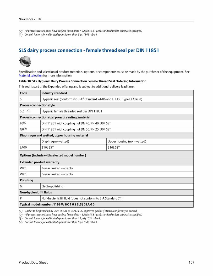
(2) All process wetted parts have surface finish of Ra < 32 μin (0.81 μm) standard unless otherwise specified.(3) Consult factory for calibrated spans lower than 5 psi (345 mbar).
SLS dairy process connection - female thread seal per DIN 11851
Specification and selection of product materials, options, or components must be made by the purchaser of the equipment. SeeMaterial selection for more information.
Table 38: SLS Hygienic Dairy Process Connection Female Thread Seal Ordering Information
This seal is part of the Expanded offering and is subject to additional delivery lead time.
Code Industry standard
S Hygienic seal (conforms to 3-A® Standard 74-06 and EHEDG Type EL Class I)
Process connection style
SLS(1)(2) Hygienic female threaded seal per DIN 11851
Process connection size, pressure rating, material
F0(3) DIN 11851 with coupling nut DN 40, PN 40, 304 SST
G0(4) DIN 11851 with coupling nut DN 50, PN 25, 304 SST
Diaphragm and wetted, upper housing material
Diaphragm (wetted) Upper housing (non-wetted)
LA00 316L SST 316L SST
Options (include with selected model number)
Extended product warranty
WR3 3-year limited warranty
WR5 5-year limited warranty
Polishing
6 Electropolishing
Non-hygienic fill fluids
P Non-hygienic fill fluid (does not conform to 3-A Standard 74)
Typical model number: 1199 W HC 1 0 S SLS J 0 LA 0 0
(1) Gasket to be furnished by user. Ensure to use EHEDG approved gasket if EHEDG conformity is needed.(2) All process wetted parts have surface finish of Ra < 32 μin (0.81 μm) standard unless otherwise specified.(3) Consult factory for calibrated spans lower than 15 psi (1034 mbar).(4) Consult factory for calibrated spans lower than 5 psi (345 mbar).
November 2018
Product Data Sheet 107
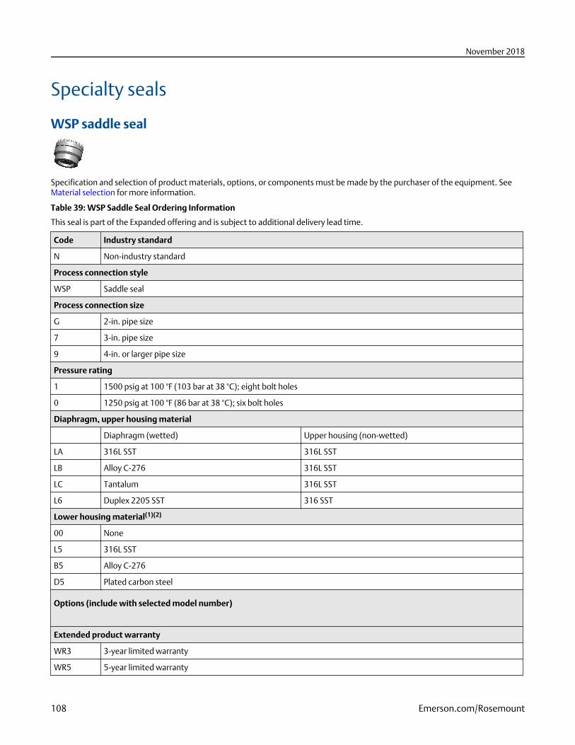
Specialty seals
WSP saddle seal
Specification and selection of product materials, options, or components must be made by the purchaser of the equipment. SeeMaterial selection for more information.
Table 39: WSP Saddle Seal Ordering Information
This seal is part of the Expanded offering and is subject to additional delivery lead time.
Code Industry standard
N Non-industry standard
Process connection style
WSP Saddle seal
Process connection size
G 2-in. pipe size
7 3-in. pipe size
9 4-in. or larger pipe size
Pressure rating
1 1500 psig at 100 °F (103 bar at 38 °C); eight bolt holes
0 1250 psig at 100 °F (86 bar at 38 °C); six bolt holes
Diaphragm, upper housing material
Diaphragm (wetted) Upper housing (non-wetted)
LA 316L SST 316L SST
LB Alloy C-276 316L SST
LC Tantalum 316L SST
L6 Duplex 2205 SST 316 SST
Lower housing material(1)(2)
00 None
L5 316L SST
B5 Alloy C-276
D5 Plated carbon steel
Options (include with selected model number)
Extended product warranty
WR3 3-year limited warranty
WR5 5-year limited warranty
November 2018
108 Emerson.com/Rosemount
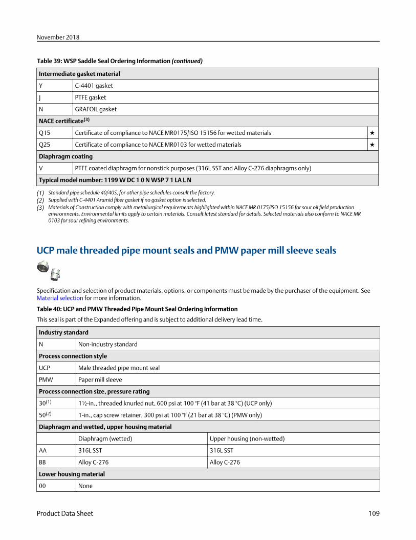
Table 39: WSP Saddle Seal Ordering Information (continued)
Intermediate gasket material
Y C-4401 gasket
J PTFE gasket
N GRAFOIL gasket
NACE certificate(3)
Q15 Certificate of compliance to NACE MR0175/ISO 15156 for wetted materials ★
Q25 Certificate of compliance to NACE MR0103 for wetted materials ★
Diaphragm coating
V PTFE coated diaphragm for nonstick purposes (316L SST and Alloy C-276 diaphragms only)
Typical model number: 1199 W DC 1 0 N WSP 7 1 LA L N
(1) Standard pipe schedule 40/40S, for other pipe schedules consult the factory.(2) Supplied with C-4401 Aramid fiber gasket if no gasket option is selected.(3) Materials of Construction comply with metallurgical requirements highlighted within NACE MR 0175/ISO 15156 for sour oil field production
environments. Environmental limits apply to certain materials. Consult latest standard for details. Selected materials also conform to NACE MR0103 for sour refining environments.
UCP male threaded pipe mount seals and PMW paper mill sleeve seals
Specification and selection of product materials, options, or components must be made by the purchaser of the equipment. SeeMaterial selection for more information.
Table 40: UCP and PMW Threaded Pipe Mount Seal Ordering Information
This seal is part of the Expanded offering and is subject to additional delivery lead time.
Industry standard
N Non-industry standard
Process connection style
UCP Male threaded pipe mount seal
PMW Paper mill sleeve
Process connection size, pressure rating
30(1) 1½-in., threaded knurled nut, 600 psi at 100 °F (41 bar at 38 °C) (UCP only)
50(2) 1-in., cap screw retainer, 300 psi at 100 °F (21 bar at 38 °C) (PMW only)
Diaphragm and wetted, upper housing material
Diaphragm (wetted) Upper housing (non-wetted)
AA 316L SST 316L SST
BB Alloy C-276 Alloy C-276
Lower housing material
00 None
November 2018
Product Data Sheet 109
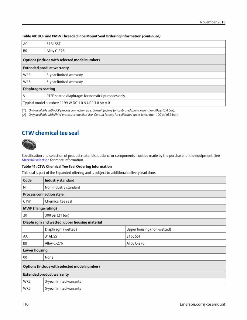
Table 40: UCP and PMW Threaded Pipe Mount Seal Ordering Information (continued)
A0 316L SST
B0 Alloy C-276
Options (include with selected model number)
Extended product warranty
WR3 3-year limited warranty
WR5 5-year limited warranty
Diaphragm coating
V PTFE coated diaphragm for nonstick purposes only
Typical model number: 1199 W DC 1 0 N UCP 3 0 AA A 0
(1) Only available with UCP process connection size. Consult factory for calibrated spans lower than 50 psi (3,4 bar).(2) Only available with PMW process connection size. Consult factory for calibrated spans lower than 100 psi (6,9 bar).
CTW chemical tee seal
Specification and selection of product materials, options, or components must be made by the purchaser of the equipment. SeeMaterial selection for more information.
Table 41: CTW Chemical Tee Seal Ordering Information
This seal is part of the Expanded offering and is subject to additional delivery lead time.
Code Industry standard
N Non-industry standard
Process connection style
CTW Chemical tee seal
MWP (flange rating)
20 300 psi (21 bar)
Diaphragm and wetted, upper housing material
Diaphragm (wetted) Upper housing (non-wetted)
AA 316L SST 316L SST
BB Alloy C-276 Alloy C-276
Lower housing
00 None
Options (include with selected model number)
Extended product warranty
WR3 3-year limited warranty
WR5 5-year limited warranty
November 2018
110 Emerson.com/Rosemount
Table 41: CTW Chemical Tee Seal Ordering Information (continued)
NACE certificate(1)
Q15 Certificate of compliance to NACE MR0175/ISO 15156 for wetted materials ★
Q25 Certificate of compliance to NACE MR0103 for wetted materials ★
Diaphragm coating
V PTFE coated diaphragm for nonstick purposes only
Typical model number: 1199 W NC 1 0 N CTW 2 0 AA 0 0
(1) Materials of Construction comply with metallurgical requirements highlighted within NACE MR 0175/ISO 15156 for sour oil field productionenvironments. Environmental limits apply to certain materials. Consult latest standard for details. Selected materials also conform to NACE MR0103 for sour refining environments.
TFS wafer style in-line seal
Specification and selection of product materials, options, or components must be made by the purchaser of the equipment. SeeMaterial selection for more information.
Table 42: TFS Wafer Style In-Line Seal Ordering Information
This seal is part of the Expanded offering and is subject to additional delivery lead time.
Code Industry standard
A ANSI/ASME B16.5 (American National Standards Institute/American Society of Mechanical Engineers)
D EN 1092-1 (European Standard)
Process connection style
TFS Wafer style in-line seal
Process connection size
ANSI/ASME B16.5 EN 1092-1
G 2-in. DN 50
7 3-in. N/A
J N/A DN 80
9 4-in. N/A
2(1) 1-in. N/A
4(2) 1½-in. N/A
D(1) N/A DN 25
F(2) N/A DN 40
K N/A DN 100
Pressure rating
0 Seal MWP based on customer supplied flange
November 2018
Product Data Sheet 111
Table 42: TFS Wafer Style In-Line Seal Ordering Information (continued)
Diaphragm and wetted, upper housing material
Diaphragm (wetted) Upper housing (non-wetted)
LA 316L SST 316L SST
Housing body length
00 3.54-in. (90 mm)
Options (include with selected model number)
Extended product warranty
WR3 3-year limited warranty
WR5 5-year limited warranty
Typical model number: 1199 W DC 1 0 A TFS 7 0 LA 0 0
(1) Consult factory for calibrated spans lower than 15 psi (1034 mbar).(2) Consult factory for calibrated spans lower than 5 psi (345 mbar).
WFW flow-through flanged seal
Specification and selection of product materials, options, or components must be made by the purchaser of the equipment. SeeMaterial selection for more information.
Table 43: WFW Flow-Through Flanged Seal Ordering Information
This seal is part of the Expanded offering and is subject to additional delivery lead time.
Code Industry standard
A ANSI/ASME B16.5 (American National Standards Institute/American Society of Mechanical Engineers)
Process connection style(1)
WFW Flow-through flanged seal
Process connection size(2)
G 2-in.
7 3-in.
2 1-in.
Flange rating(2)
1 Class 150
Diaphragm, upper housing material
Diaphragm (wetted) Upper housing (non-wetted)(2)
LA 316L SST 316L SST
LC Tantalum 316L SST
November 2018
112 Emerson.com/Rosemount
Table 43: WFW Flow-Through Flanged Seal Ordering Information (continued)
Lower housing material(1)
L 316L SST
Pipe schedule(2)
N 40/40S
Options (include with selected model number)
Extended product warranty
WR3 3-year limited warranty
WR5 5-year limited warranty
Gasket material
Y C-4401 gasket
J PTFE O-ring
K Barium sulfate filled PTFE gasket
N GRAFOIL gasket
R Ethylene propylene gasket
Bolt material
3 304 SST bolts
NACE certificate(3)
Q15 Certificate of compliance to NACE MR0175/ISO 15156 for wetted materials
Q25 Certificate of compliance to NACE MR0103 for wetted materials
Cold temperature application
B Extra fill for cold temperature application
Typical model number: 1199 W DC 1 0 A WFW 7 1 LA L N
(1) Supplied with C-4401 Aramid fiber gasket if no other gasket option is selected.(2) Consult factory for special process connection sizes, flange pressure ratings, diaphragm/lower housing materials, and pipe schedules.(3) Materials of Construction comply with metallurgical requirements highlighted within NACE MR 0175/ISO 15156 for sour oil field production
environments. Environmental limits apply to certain materials. Consult latest standard for details. Selected materials also conform to NACE MR0103 for sour refining environments.
Specifications
Liquid level transmitter specifications
Performance specificationsFor zero-based spans, reference conditions, silicone oil fill, glass-filled PTFE O-rings, SST materials, coplanar flange (Rosemount3051SMV, 3051S_C) or ½–14 NPT (Rosemount 3051S_T) process connections, digital trim values set to equal range points.
Conformance to specification (±3σ [Sigma])
Technology leadership, advanced manufacturing techniques, and statistical process control ensure measurement specificationconformance to ±3σ or better.
November 2018
Product Data Sheet 113
Reference accuracy
Stated reference accuracy equations include terminal based linearity, hysteresis, and repeatability, but does not include analogoutput reference accuracy of ±0.005% of span.
Table 44: DP Total Accuracy for Enhanced ERS System Performance
Includes full ambient and temperature range from –40 to 85 °C (–40 to 185 °F) requires two transmitters with identical sensorranges. Specification are only applicable for spans down to 10:1.
Sensor type 3051SAM__G2, 3051SAL__G2 250 inH2O(622,1 mbar)
3051SAM__G3, 3051SAL__G3 1000inH2O (2488,4mbar)
3051SAM__T1, 3051SAL__T1 30 psi (2,1bar)
3051SAM_ _T2,3051SAL_ _T2150 psi (10,34bar)
3051SAM__G4, 3051SAL__G4 300 psi(20,7 bar)
3051SAM__T3, 3051SAL__T3 800 psi
(55,2 bar)
Rosemount™
3051SAM(1)0.2 inH2O
(0,5 mbar)
0.6 inH2O
(1,4 mbar)
0.9 inH2O
(2,2 mbar)
1.5 inH2O
(4,0 mbar)
6.2 inH2O
(15 mbar)
7.8 inH2O
(19 mbar)
Rosemount 3051SALwith direct mount sealtypes and sizes below(2)
■ FF, FC, PF ≥ 2-in./DN50
■ EF ≥ 3-in./DN80■ All RT, RF, RC, SS■ SC ≥ 2.5-in.
2.2 inH2O
(5,5 mbar)
2.3 inH2O
(5,8 mbar)
3.0 inH2O
(7,5 mbar)
3.2 inH2O
(8,0 mbar)
6.5 inH2O
(16 mbar)
8.3 inH2O
(21 mbar)
Rosemount 3051SALwith other seal typesand sizes
Consult Instrument Toolkit™ for performance.
(1) For Rosemount 3051SAM assembled to a Rosemount 1199 Diaphragm Seal, use Rosemount 3051SAL specification for identical seal types andsizes.
(2) For Rosemount 3051SAL with direct mount seals, specification applies to process temperatures from -45 to 205 °C and excludes diaphragmoption code SC, 6-mil diaphragm thickness. Seal types outside these parameters will require a Toolkit calculation for performance.
Table 45: DP Reference Accuracy of Rosemount 3051S ERS System
Ultra Classic
Two coplanar gage sensors (Rosemount 3051SAM_ _G)
Ranges 2–4 ±0.035% of DP span ±0.049% of DP span
Range 5 ±0.071% of DP span ±0.092% of DP span
Two coplanar (Rosemount 3051SAM_ _A)
Ranges 1–4 ±0.035% of DP span ±0.049% of DP span
Two in-line gage sensors (Rosemount 3051SAM_ _T) Two in-line absolute sensors (Rosemount 3051SAM_ _E)
Ranges 1–4 ±0.035% of DP span ±0.049% of DP span
Two liquid level sensors (Rosemount 3051SAL)
Ranges 1–5 ±0.092% of DP span ±0.092% of DP span
Table 46: Reference Accuracy for FOUNDATION™ Fieldbus and Wireless Devices
For FOUNDATION Fieldbus and wireless devices, use calibrated range in place of span.
November 2018
114 Emerson.com/Rosemount
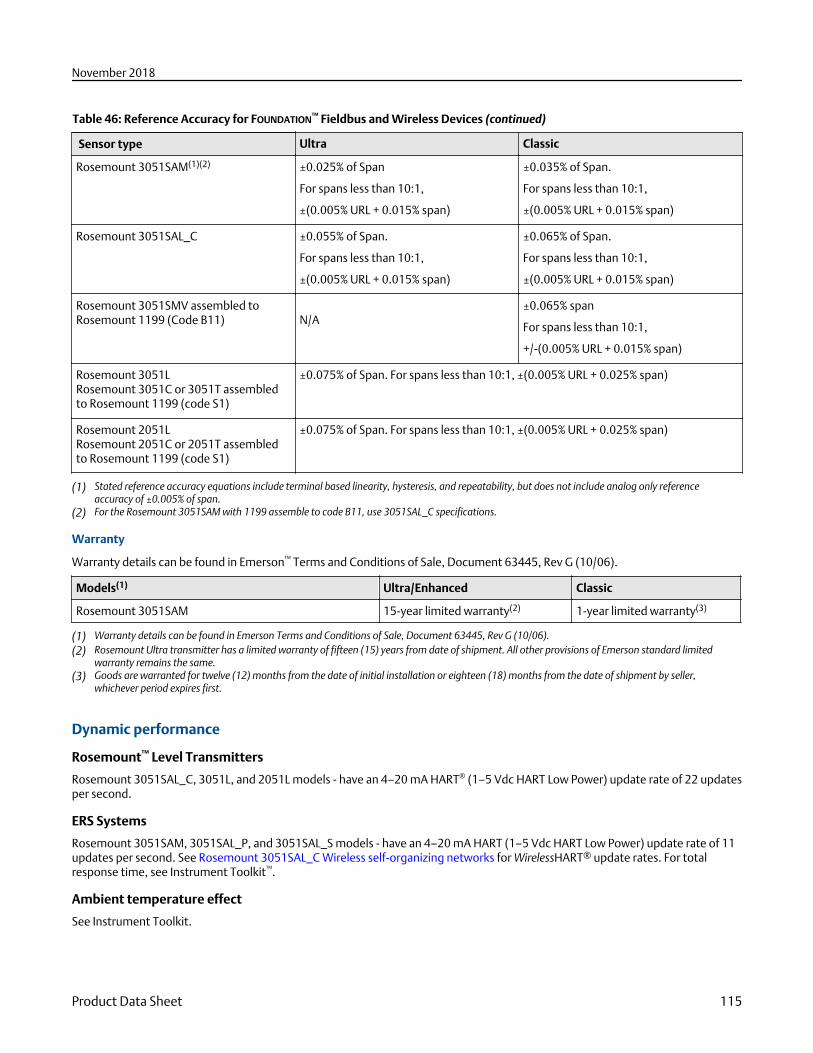
Table 46: Reference Accuracy for FOUNDATION™ Fieldbus and Wireless Devices (continued)
Sensor type Ultra Classic
Rosemount 3051SAM(1)(2) ±0.025% of Span
For spans less than 10:1,
±(0.005% URL + 0.015% span)
±0.035% of Span.
For spans less than 10:1,
±(0.005% URL + 0.015% span)
Rosemount 3051SAL_C ±0.055% of Span.
For spans less than 10:1,
±(0.005% URL + 0.015% span)
±0.065% of Span.
For spans less than 10:1,
±(0.005% URL + 0.015% span)
Rosemount 3051SMV assembled toRosemount 1199 (Code B11)
N/A
±0.065% span
For spans less than 10:1,
+/-(0.005% URL + 0.015% span)
Rosemount 3051LRosemount 3051C or 3051T assembledto Rosemount 1199 (code S1)
±0.075% of Span. For spans less than 10:1, ±(0.005% URL + 0.025% span)
Rosemount 2051LRosemount 2051C or 2051T assembledto Rosemount 1199 (code S1)
±0.075% of Span. For spans less than 10:1, ±(0.005% URL + 0.025% span)
(1) Stated reference accuracy equations include terminal based linearity, hysteresis, and repeatability, but does not include analog only referenceaccuracy of ±0.005% of span.
(2) For the Rosemount 3051SAM with 1199 assemble to code B11, use 3051SAL_C specifications.
Warranty
Warranty details can be found in Emerson™ Terms and Conditions of Sale, Document 63445, Rev G (10/06).
Models(1) Ultra/Enhanced Classic
Rosemount 3051SAM 15-year limited warranty(2) 1-year limited warranty(3)
(1) Warranty details can be found in Emerson Terms and Conditions of Sale, Document 63445, Rev G (10/06).(2) Rosemount Ultra transmitter has a limited warranty of fifteen (15) years from date of shipment. All other provisions of Emerson standard limited
warranty remains the same.(3) Goods are warranted for twelve (12) months from the date of initial installation or eighteen (18) months from the date of shipment by seller,
whichever period expires first.
Dynamic performance
Rosemount™ Level Transmitters
Rosemount 3051SAL_C, 3051L, and 2051L models - have an 4–20 mA HART® (1–5 Vdc HART Low Power) update rate of 22 updatesper second.
ERS Systems
Rosemount 3051SAM, 3051SAL_P, and 3051SAL_S models - have an 4–20 mA HART (1–5 Vdc HART Low Power) update rate of 11updates per second. See Rosemount 3051SAL_C Wireless self-organizing networks for WirelessHART® update rates. For totalresponse time, see Instrument Toolkit™.
Ambient temperature effect
See Instrument Toolkit.
November 2018
Product Data Sheet 115
Mounting position effects
With liquid level remote mount seal in vertical plane, zero shift of up to ±1 inH2O (2,49 mbar); with remote mount seal in horizontalplane, zero shift of up to ±5 inH2O (12,45 mbar) plus extension length on extended units; all zero shifts can be zeroed; no spaneffect.
Vibration effect
Rosemount3051SAM3051SAL
Less than ±0.1% of URL when tested per the requirements of IEC60770-1 field or pipeline with high vibrationlevel (10–60 Hz 0.21mm displacement peak amplitude/60–2000 Hz 3g).
For Housing Style codes 1J, 1K, 1L, 2J, and 2M: Less than ±0.1% of URL when tested per the requirements ofIEC60770-1 field with general application or pipeline with low vibration level (10–60 Hz 0.15 mmdisplacement peak amplitude/60–500 Hz 2g).
Rosemount3051L
Measurement effect due to vibrations is negligible except at resonance frequencies. When at resonancefrequencies, vibration effect is less than ±0.1% of URL per g when tested between 15 and 2000 Hz in any axisrelative to pipe-mounted process conditions.
Rosemount2051L
Less than ±0.1% of URL when tested per the requirements of IEC60770-1 field or pipeline with high vibrationlevel (10–60 Hz 0.21 mm displacement peak amplitude/60–2000 Hz 3 g)
Power supply effect
Less than ±0.005 percent of calibrated span per volt.
Electromagnetic Compatibility (EMC)
Transient protection (option T1)
Rosemount3051SAM 3051SAL
Meets IEEE C62.41.2-2002, Location Category B 6 kV crest (0.5 µs–100 kHz) 3 kA crest (8 × 20microseconds) 6 kV crest (1.2× 50 microseconds).
Rosemount 3051L Meets IEEE C62.41, Category B 6 kV crest (0.5 µs–100 kHz) 3 kV crest (8 × 20 microseconds) 6 kV crest(1.2 × 50 microseconds).
Rosemount 2051L Meets IEEE C62.41, Location Category B 6 kV crest (0.5 µs–100 kHz) 3 kV crest (8 × 20 microseconds) 6 kVcrest (1.2 × 50 microseconds).
Functional specifications
Range and sensor limits
Table 47: Rosemount 3051SAM_ _G, 3051SAL_ _D, 3051SAL_ _G
Range Minimum span Range limits
Ultra Classic Upper (URL) Lower (LRL)
3051SAL_G(1)(2) 3051SAL_D(1)
2 1.3 inH2O
(3,11 mbar)
2.5 inH2O
(6,23 mbar)
250.0 inH2O
(0,62 bar)
–250.0 inH2O
(–0,62 bar)
–250.0 inH2O
(–0,62 bar)
3 5.0 inH2O
(12,4 mbar)
10.0 inH2O
(24,9 mbar)
1000.0 inH2O
(2,49 bar)
–393.0 inH2O
(–979 mbar)
–1000.0 inH2O
(–2,49 bar)
4 1.5 psi
(103,4 mbar)
3.0 psi
(206,8 mbar)
300.0 psi
(20,7 bar)
–14.2 psig
(–979 mbar)
–300.0 psi
–20,7 bar)
November 2018
116 Emerson.com/Rosemount
Table 47: Rosemount 3051SAM_ _G, 3051SAL_ _D, 3051SAL_ _G (continued)
Range Minimum span Range limits
Ultra Classic Upper (URL) Lower (LRL)
3051SAL_G(1)(2) 3051SAL_D(1)
5 10.0 psi
(689,5 mbar)
20.0 psi
(1,38 bar)
2000.0 psi
(137,9 bar)
–14.2 psig
(–979 mbar)
–2000.0 psi
(–137,9 bar)
(1) When specifying a Rosemount 3051SAL Ultra, use Classic minimum span. Minimum span limits may also be limited by the remote seal that isspecified with the system.
(2) Assumes atmospheric pressure of 14.7 psig (1 bar).
Table 48: Rosemount 3051SAM_ _A, 3051SAL_ _A
When specifying a Rosemount 3051SAL Ultra, use Classic minimum span. Minimum span limits may also be limited by the remoteseal that is specified with the system.
Range Minimum span Range and sensor limits
Upper (URL) Lower (LRL)Ultra Classic
1 0.3 psia (20,7 mbar) 0.3 psia (20,7 mbar) 30 psia (2,07 bar) 0 psia (0 bar)
2 0.75 psia (51,7 mbar) 1.5 psia (0,103 bar) 150 psia (10,34 bar) 0 psia (0 bar)
3 4 psia (275,8 mbar) 8 psia (0,55 bar) 800 psia (55,16 bar) 0 psia (0 bar)
4 20 psia (1,38 bar) 40 psia (2,76 bar) 4000 psia (275,8 bar) 0 psia (0 bar)
Table 49: Rosemount 3051SAM_ _T, 3051SAM_ _E, 3051SAL_ _T, 3051SAL_ _E
Range Minimum span Range and sensor limits
Ultra Classic Upper (URL) Lower (LRL) (Abs.) Lower(1) (LRL) (Gage)
1 0.3 psi (20,7 mbar) 0.3 psi (20,7 mbar) 30 psi (2,07 bar) 0 psia (0 bar) –14.7 psig (–1,01 bar)
2 0.75 psi (51,7 mbar) 1.5 psi (0,103 bar) 150 psi (10,34 bar) 0 psia (0 bar) –14.7 psig (–1,01 bar)
3 4 psi (275,8 mbar) 8 psi (0,55 bar) 800 psi (55,16 bar) 0 psia (0 bar) –14.7 psig (–1,01 bar)
4 20 psi (1,38 bar) 40 psi (2,76 bar) 4000 psi (275,8 bar) 0 psia (0 bar) –14.7 psig (–1,01 bar)
5 1000 psi (68,9 bar) 2000 psi (137,9 bar) 10000 psi (689,5bar)
0 psia (0 bar) –14.7 psig (–1,01 bar)
(1) Assumes atmospheric pressure of 14.7 psig (1 bar).
Table 50: Rosemount 3051L
Range Minimum span Range and sensor limits
Upper (URL) Lower (LRL)
Rosemount 3051LDifferential
Rosemount 3051L Gage(1)
2 2.5 inH2O (6,2 mbar) 250 inH2O (0,62 bar) –250 inH2O (–0,62 bar) –250 inH2O (–0,62 bar)
3 10 inH2O (24,9 mbar) 1000 inH2O (2,49 bar) –1000 inH2O (–2,49 bar) -393 inH2O (-979 mbar)
4 3 psi (0,20 bar) 300 psi (20,6 bar) –300 psi (–20,6 bar) -14.2 psig (979 mbar)
5 20 psi (1,38 bar) 2000 psi (137,9 bar) N/A N/A
(1) Assumes atmospheric pressure of 14.7 psig.
November 2018
Product Data Sheet 117
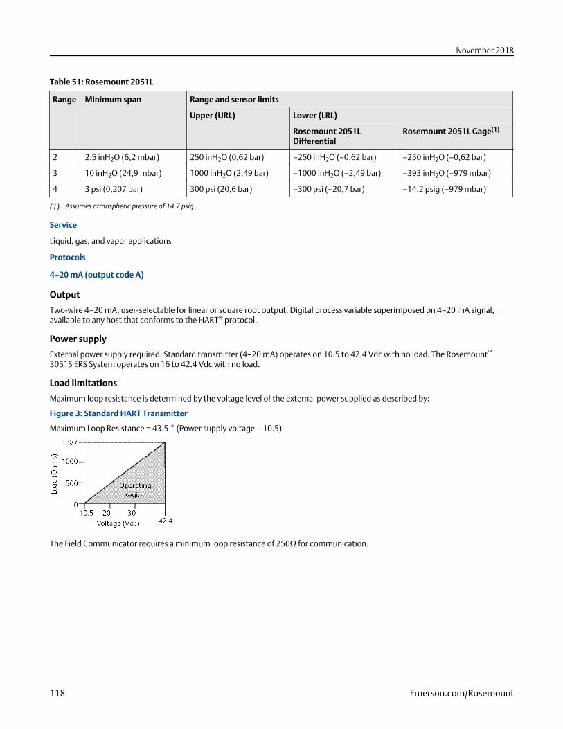
Table 51: Rosemount 2051L
Range Minimum span Range and sensor limits
Upper (URL) Lower (LRL)
Rosemount 2051LDifferential
Rosemount 2051L Gage(1)
2 2.5 inH2O (6,2 mbar) 250 inH2O (0,62 bar) –250 inH2O (–0,62 bar) –250 inH2O (–0,62 bar)
3 10 inH2O (24,9 mbar) 1000 inH2O (2,49 bar) –1000 inH2O (–2,49 bar) –393 inH2O (–979 mbar)
4 3 psi (0,207 bar) 300 psi (20,6 bar) –300 psi (–20,7 bar) –14.2 psig (–979 mbar)
(1) Assumes atmospheric pressure of 14.7 psig.
Service
Liquid, gas, and vapor applications
Protocols
4–20 mA (output code A)
Output
Two-wire 4–20 mA, user-selectable for linear or square root output. Digital process variable superimposed on 4–20 mA signal,available to any host that conforms to the HART® protocol.
Power supply
External power supply required. Standard transmitter (4–20 mA) operates on 10.5 to 42.4 Vdc with no load. The Rosemount™
3051S ERS System operates on 16 to 42.4 Vdc with no load.
Load limitations
Maximum loop resistance is determined by the voltage level of the external power supplied as described by:
Figure 3: Standard HART Transmitter
Maximum Loop Resistance = 43.5 * (Power supply voltage – 10.5)
The Field Communicator requires a minimum loop resistance of 250Ω for communication.
November 2018
118 Emerson.com/Rosemount
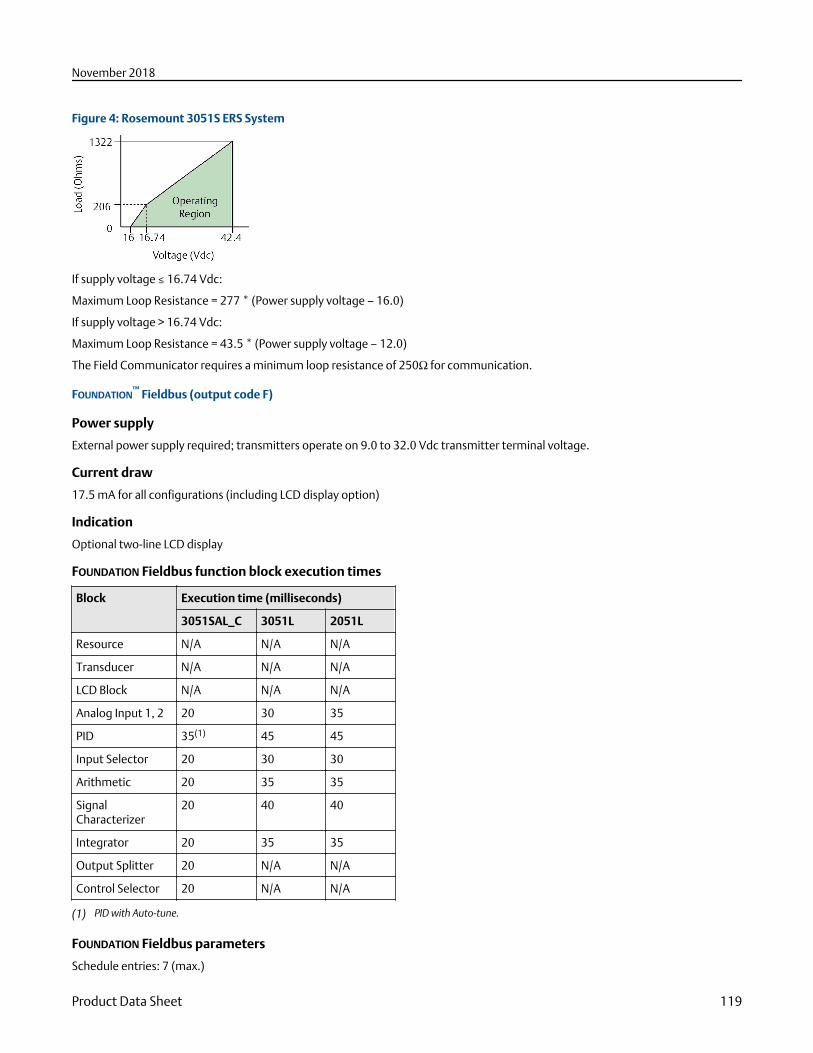
Figure 4: Rosemount 3051S ERS System
If supply voltage ≤ 16.74 Vdc:
Maximum Loop Resistance = 277 * (Power supply voltage – 16.0)
If supply voltage > 16.74 Vdc:
Maximum Loop Resistance = 43.5 * (Power supply voltage – 12.0)
The Field Communicator requires a minimum loop resistance of 250Ω for communication.
FOUNDATION™ Fieldbus (output code F)
Power supply
External power supply required; transmitters operate on 9.0 to 32.0 Vdc transmitter terminal voltage.
Current draw
17.5 mA for all configurations (including LCD display option)
Indication
Optional two-line LCD display
FOUNDATION Fieldbus function block execution times
Block Execution time (milliseconds)
3051SAL_C 3051L 2051L
Resource N/A N/A N/A
Transducer N/A N/A N/A
LCD Block N/A N/A N/A
Analog Input 1, 2 20 30 35
PID 35(1) 45 45
Input Selector 20 30 30
Arithmetic 20 35 35
SignalCharacterizer
20 40 40
Integrator 20 35 35
Output Splitter 20 N/A N/A
Control Selector 20 N/A N/A
(1) PID with Auto-tune.
FOUNDATION Fieldbus parameters
Schedule entries: 7 (max.)
November 2018
Product Data Sheet 119
Links: 20 (max.)
Virtual Communications Relationships (VCR): 12 (max.)
Standard function blocks
Resource block
Contains hardware, electronics, and diagnostic information.
Transducer block
Contains actual sensor measurement data including the sensor diagnostics and the ability to trim the pressure sensor or recallfactory defaults.
LCD block
Configures the local display.
Two analog input blocks
Processes the measurements for input into other function blocks. The output value is in engineering units or custom and contains astatus indicating measurement quality.
PID block
Contains all logic to perform PID control in the field including cascade and feedforward.
Backup Link Active Scheduler (LAS)The transmitter can function as a Link Active Scheduler if the current link master device fails or is removed from the segment.
Advanced control function block suite (option code A01)
Input selector block
Selects between inputs and generates an output using specific selection strategies such as minimum, maximum, midpoint,average, or first “good.”
Arithmetic block
Provides pre-defined application-based equations including flow with partial density compensation, electronic remote seals,hydrostatic tank gauging, ratio control, and others.
Signal characterizer block
Characterizes or approximates any function that defines an input/output relationship by configuring up to twenty X, Y coordinates.The block interpolates an output value for a given input value using the curve defined by the configured coordinates.
Integrator block
Compares the integrated or accumulated value from one or two variables to pre-trip and trip limits and generates discrete outputsignals when the limits are reached. This block is useful for calculating total flow, total mass, or volume over time.
FOUNDATION™ Fieldbus diagnostics suite (option code D01)The FOUNDATION Fieldbus Diagnostics provide Abnormal Situation Prevention (ASP) indication. The integral statistical processmonitoring (SPM) technology calculates the mean and standard deviation of the process variable 22 times per second. TheRosemount™ 3051S_L and 3051L use these values and highly flexible configuration options for customization to detect many user-defined or application specific abnormal situations (e.g. detecting plugged impulse lines and fluid composition change).
PROFIBUS® PA (output code W)
Profile version
3.02
November 2018
120 Emerson.com/Rosemount
Power supply
External power supply required; transmitters operate on 9.0 to 32.0 Vdc transmitter terminal voltage.
Current draw
17.5 mA for all configurations (including LCD display option)
Output update rate
Four times per second
Standard function blocks
Analog input (AI block)
The AI function block processes the measurements and makes them available to the host device. The output value from the AIblock is in engineering units and contains a status indicating the quality of the measurement.
Physical block
The physical block defines the physical resources of the device including type of memory, hardware, electronics, and diagnosticinformation.
Transducer block
Contains actual sensor measurement data including the sensor diagnostics and the ability to trim the pressure sensor or recallfactory defaults.
Indication
Optional two-line LCD display
Local Operator Interface
Optional external configuration buttons
Rosemount 3051SAL_C Wireless self-organizing networks
Output
IEC 62591 (WirelessHART®), 2.4 GHz DSSS
Radio frequency power output from antenna
External antenna (WK option): Maximum of 10 mW (10 dBm) EIRP
Extended range, external antenna (WM option): Maximum of 18 mW (12.5 dBm) EIRP
High-gain, remote antenna (WN option): Maximum of 40 mW (16 dBm) EIRP
Local display
The optional seven-digit LCD display can display primary variable in engineering units, percent of range, sensor moduletemperature, and electronics temperature. Display updates at update rate up to once per minute. The display updates based onthe wireless update rate.
Update rate
User selectable 1 second to 60 minutes.
Power module
Field replaceable, keyed connection eliminates the risk of incorrect installation, Intrinsically Safe Lithium-thionyl chloride PowerModule with polybutadine terephthalate (PBT) enclosure. Ten-year life at one-minute update rate.
NoteReference conditions are 70 °F (21 °C), and routing data for three additional network devices. Continuous exposure to ambienttemperature limits of –40 °F or 185 °F (–40 °C or 85 °C) may reduce specified life by less than 20 percent.
November 2018
Product Data Sheet 121
Overpressure limits
Limit is 0 psia to the flange rating or sensor rating, whichever is lower.
Table 52: Rosemount 3051L, 2051L, and Level Flange Rating Limits
Standard Type CS Rating SST Rating
ANSI/ASME Class 150 285 psig 275 psig
ANSI/ASME Class 300 740 psig 720 psig
ANSI/ASME Class 600 1480 psig 1440 psig
At 100 °F (38 °C), the rating decreases with increasing temperature, per ANSI/ASME B16.5.
DIN PN 10–40 40 bar 40 bar
DIN PN 10/16 16 bar 16 bar
DIN PN 25/40 40 bar 40 bar
At 122 °F (50 °C), the rating decreases with increasing temperature per EN 1092-1 Annex F.
Temperature limits
Ambient
–40 to 185 °F (–40 to 85 °C) With LCD display(1): –40 to 175 °F (–40 to 80 °C) With option code P0: –20 to 185 °F (–29 to 85 °C)
Storage
–50 to 185 °F (–46 to 85 °C) With LCD display: –40 to 185 °F (–40 to 85 °C) With wireless output: –40 to 185 °F (–40 to 85 °C)
Process
Table 53: Rosemount 3051SAM ERS Process temperature Limits (Gage/Absolute Sensor)
Configuration Coplanar gage/absolute sensor
(Rosemount 3051SAM_ _G, 3051SAM_ _A)
In-line gage sensor/absolute sensor
(Rosemount 3051SAM_ _T, 3051SAM_ _E)
Silicone fill fluid(1) N/A –40 to 250 °F (–40 to 121 °C)(3)
with coplanar flange(2) –40 to 250 °F (–40 to 121 °C)(3) N/A
with traditional flange(2) –40 to 300 °F (–40 to 149 °C)(3) N/A
with level flange(2) –40 to 300 °F (–40 to 149 °C)(3) N/A
with Rosemount 305Integral Manifold(2)
–40 to 300 °F (–40 to 149 °C)(3) N/A
Inert fill fluid(2)(4) –40 to 185 °F (–40 to 85 °C)(5) –22 to 250 °F (–30 to 121 °C)(3)
(1) Process temperatures above 185 °F (85 °C) require de-rating the ambient limits by a 1.5:1 ratio. For example, for process temperature of 195 °F(91 °C), new ambient temperature limit is equal to 170 °F (77 °C). This can be determined as follows: (195 °F – 185 °F) × 1.5 = 15 °F, 185 °F –15 °F= 170 °F.
(2) Process temperatures above 185 °F (85 °C) require de-rating the ambient limits by a 1:1 ratio.(3) 220 °F (104 °C) limit in vacuum service; 130 °F (54 °C) for pressures below 0.5 psia.(4) Not available with Rosemount 3051SAM_ _A.(5) 160 °F (71 °C) limit in vacuum service.
(1) LCD display may not be readable and LCD display updates will be slower at temperatures below –4 °F (–20 °C).
November 2018
122 Emerson.com/Rosemount
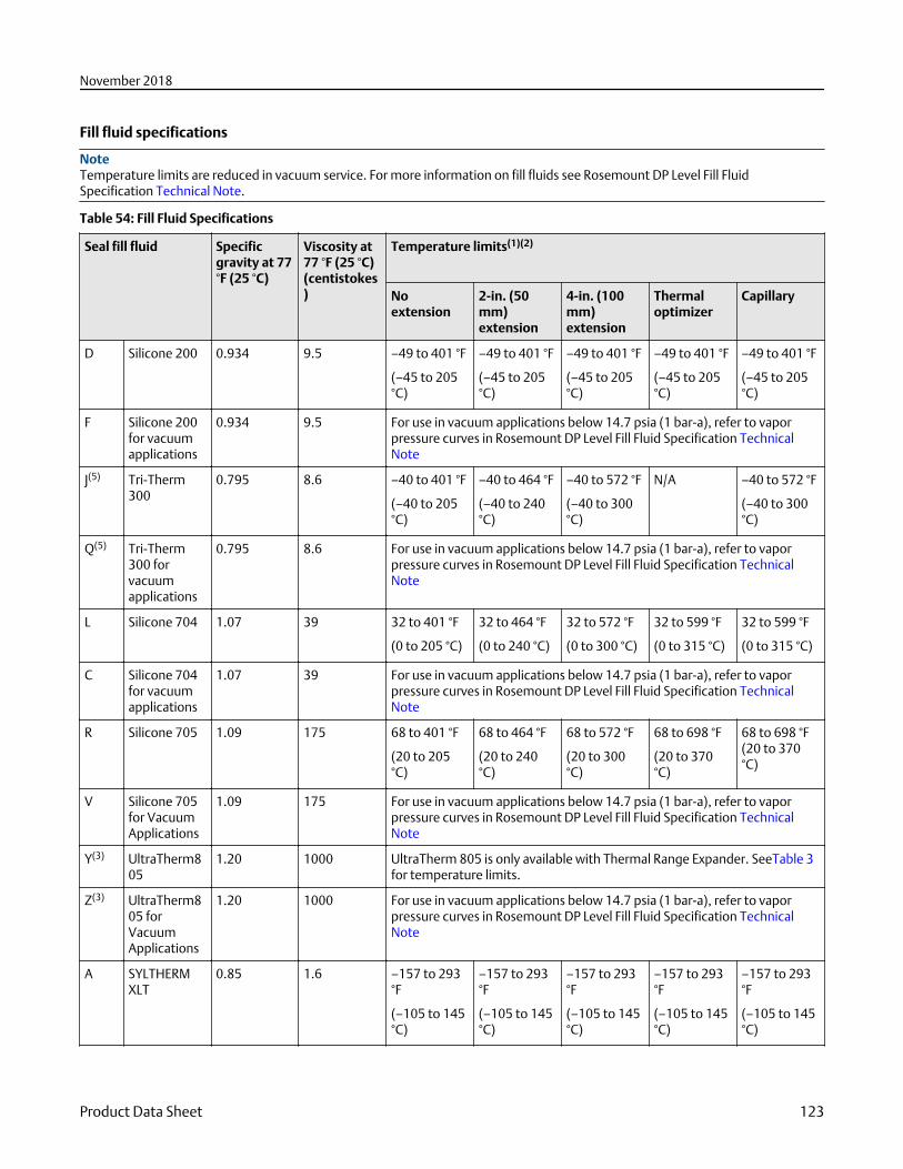
Fill fluid specifications
NoteTemperature limits are reduced in vacuum service. For more information on fill fluids see Rosemount DP Level Fill FluidSpecification Technical Note.
Table 54: Fill Fluid Specifications
Seal fill fluid Specificgravity at 77°F (25 °C)
Viscosity at77 °F (25 °C)(centistokes)
Temperature limits(1)(2)
Noextension
2-in. (50mm)extension
4-in. (100mm)extension
Thermaloptimizer
Capillary
D Silicone 200 0.934 9.5 –49 to 401 °F
(–45 to 205°C)
–49 to 401 °F
(–45 to 205°C)
–49 to 401 °F
(–45 to 205°C)
–49 to 401 °F
(–45 to 205°C)
–49 to 401 °F
(–45 to 205°C)
F Silicone 200for vacuumapplications
0.934 9.5 For use in vacuum applications below 14.7 psia (1 bar-a), refer to vaporpressure curves in Rosemount DP Level Fill Fluid Specification TechnicalNote
J(5) Tri-Therm300
0.795 8.6 –40 to 401 °F
(–40 to 205°C)
–40 to 464 °F
(–40 to 240°C)
–40 to 572 °F
(–40 to 300°C)
N/A –40 to 572 °F
(–40 to 300°C)
Q(5) Tri-Therm300 forvacuumapplications
0.795 8.6 For use in vacuum applications below 14.7 psia (1 bar-a), refer to vaporpressure curves in Rosemount DP Level Fill Fluid Specification TechnicalNote
L Silicone 704 1.07 39 32 to 401 °F
(0 to 205 °C)
32 to 464 °F
(0 to 240 °C)
32 to 572 °F
(0 to 300 °C)
32 to 599 °F
(0 to 315 °C)
32 to 599 °F
(0 to 315 °C)
C Silicone 704for vacuumapplications
1.07 39 For use in vacuum applications below 14.7 psia (1 bar-a), refer to vaporpressure curves in Rosemount DP Level Fill Fluid Specification TechnicalNote
R Silicone 705 1.09 175 68 to 401 °F
(20 to 205°C)
68 to 464 °F
(20 to 240°C)
68 to 572 °F
(20 to 300°C)
68 to 698 °F
(20 to 370°C)
68 to 698 °F(20 to 370°C)
V Silicone 705for VacuumApplications
1.09 175 For use in vacuum applications below 14.7 psia (1 bar-a), refer to vaporpressure curves in Rosemount DP Level Fill Fluid Specification TechnicalNote
Y(3) UltraTherm805
1.20 1000 UltraTherm 805 is only available with Thermal Range Expander. SeeTable 3for temperature limits.
Z(3) UltraTherm805 forVacuumApplications
1.20 1000
For use in vacuum applications below 14.7 psia (1 bar-a), refer to vaporpressure curves in Rosemount DP Level Fill Fluid Specification TechnicalNote
A SYLTHERMXLT
0.85 1.6 –157 to 293°F
(–105 to 145°C)
–157 to 293°F
(–105 to 145°C)
–157 to 293°F
(–105 to 145°C)
–157 to 293°F
(–105 to 145°C)
–157 to 293°F
(–105 to 145°C)
November 2018
Product Data Sheet 123
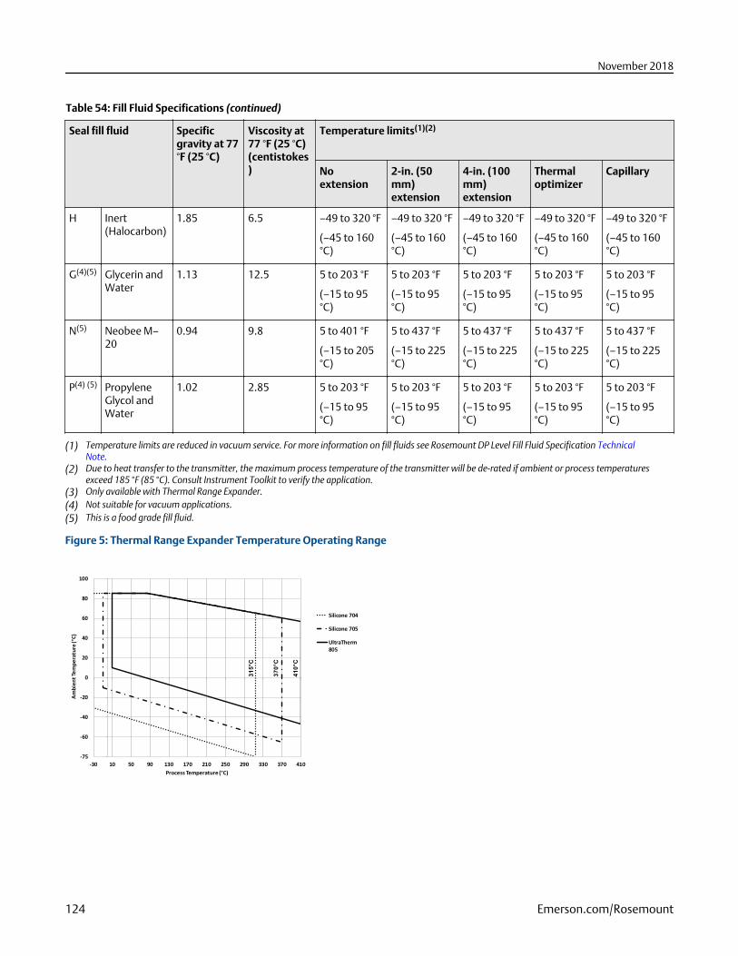
Table 54: Fill Fluid Specifications (continued)
Seal fill fluid Specificgravity at 77°F (25 °C)
Viscosity at77 °F (25 °C)(centistokes)
Temperature limits(1)(2)
Noextension
2-in. (50mm)extension
4-in. (100mm)extension
Thermaloptimizer
Capillary
H Inert(Halocarbon)
1.85 6.5 –49 to 320 °F
(–45 to 160°C)
–49 to 320 °F
(–45 to 160°C)
–49 to 320 °F
(–45 to 160°C)
–49 to 320 °F
(–45 to 160°C)
–49 to 320 °F
(–45 to 160°C)
G(4)(5) Glycerin andWater
1.13 12.5 5 to 203 °F
(–15 to 95°C)
5 to 203 °F
(–15 to 95°C)
5 to 203 °F
(–15 to 95°C)
5 to 203 °F
(–15 to 95°C)
5 to 203 °F
(–15 to 95°C)
N(5) Neobee M–20
0.94 9.8 5 to 401 °F
(–15 to 205°C)
5 to 437 °F
(–15 to 225°C)
5 to 437 °F
(–15 to 225°C)
5 to 437 °F
(–15 to 225°C)
5 to 437 °F
(–15 to 225°C)
P(4) (5) PropyleneGlycol andWater
1.02 2.85 5 to 203 °F
(–15 to 95°C)
5 to 203 °F
(–15 to 95°C)
5 to 203 °F
(–15 to 95°C)
5 to 203 °F
(–15 to 95°C)
5 to 203 °F
(–15 to 95°C)
(1) Temperature limits are reduced in vacuum service. For more information on fill fluids see Rosemount DP Level Fill Fluid Specification TechnicalNote.
(2) Due to heat transfer to the transmitter, the maximum process temperature of the transmitter will be de-rated if ambient or process temperaturesexceed 185 °F (85 °C). Consult Instrument Toolkit to verify the application.
(3) Only available with Thermal Range Expander.(4) Not suitable for vacuum applications.(5) This is a food grade fill fluid.
Figure 5: Thermal Range Expander Temperature Operating Range
-75
-60
-40
-20
0
20
40
60
80
100
-30 10 50 90 130 170 210 250 290 330 370 410
Am
bie
nt
Tem
pe
ratu
re (
°C)
Process Temperature (°C)
Silicone 704
Silicone 705
UltraTherm
805
315°C
370°C
410°C
November 2018
124 Emerson.com/Rosemount
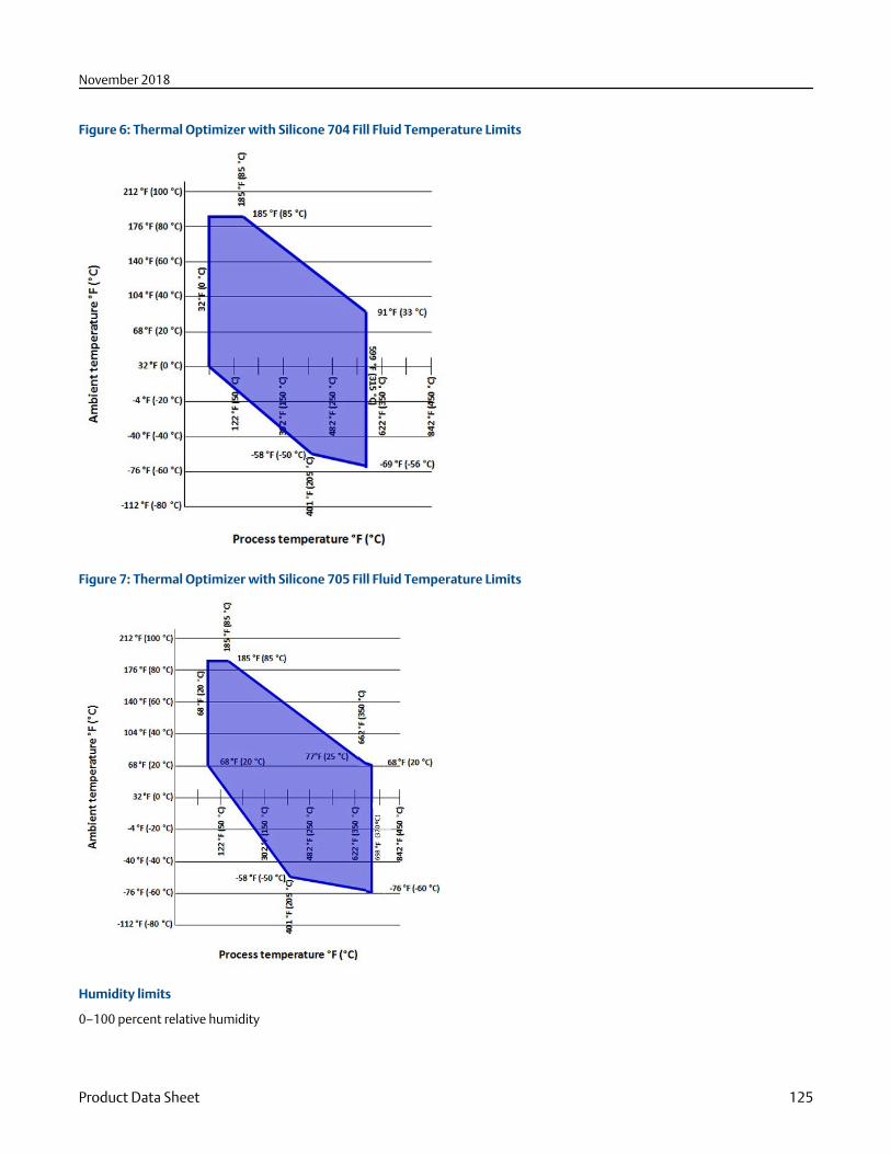
Figure 6: Thermal Optimizer with Silicone 704 Fill Fluid Temperature Limits
Figure 7: Thermal Optimizer with Silicone 705 Fill Fluid Temperature Limits
Humidity limits
0–100 percent relative humidity
November 2018
Product Data Sheet 125
Turn-on time
Rosemount3051SAL_C
Performance within specifications less than 2.0 seconds after power is applied to the transmitter.
Rosemount3051L
Performance within specifications less than 2.0 seconds (10.0 s for PROFIBUS protocol) after power is applied tothe transmitter
Rosemount2051L
Performance within specifications less than 2.0 seconds after power is applied to the transmitter.
RosemountERS System
Performance within specifications less than 6.0 seconds after power is applied.
Volumetric displacement
Less than 0.005-in.3 (0.08 cm3)
Damping
Software damping is in addition to sensor module response time.
NoteDoes not apply to wireless option code X.
Rosemount 3051SAL_C Analog output response to a step change is user-selectable from 0 to 60 seconds for one time constant.
Rosemount 3051L Analog output response to a step input change is user-selectable from 0 to 36 seconds for one timeconstant.
Rosemount 2051L Analog output response to a step input change is user-selectable from 0 to 25.6 seconds for one timeconstant.
Rosemount ERS System The PHI and PLO pressure measurements and the DP calculation may be independently dampenedfrom 0 to 60 seconds for one time constant.
Physical specifications
Material selection
Emerson™ provides a variety of Rosemount™ products with various product options and configurations including materials ofconstruction that can be expected to perform well in a wide range of applications. The Rosemount product information presentedis intended as a guide for the purchaser to make an appropriate selection for the application. It is the purchaser’s sole responsibilityto make a careful analysis of all process parameters (such as all chemical components, temperature, pressure, flow rate, abrasives,contaminants, etc.), when specifying product, materials, options and components for the particular application. Emerson is not in aposition to evaluate or guarantee the compatibility of the process fluid or other process parameters with the product, options,configuration or materials of construction selected.
NoteIf a lower housing is supplied, then the following gaskets are the default gaskets for each seal unless another gasket option isselected.
Electrical connections
½–14 NPT, PG 13.5, G½, and M20 × 1.5 conduit. HART interface connections fixed to terminal block.
Non-wetted parts
Transmitter flange is CF-3M (cast version of 316L SST, material per ASTM-A743)
Capillary tube is 316L SST
Capillary armor is SST or PVC coated SST
November 2018
126 Emerson.com/Rosemount
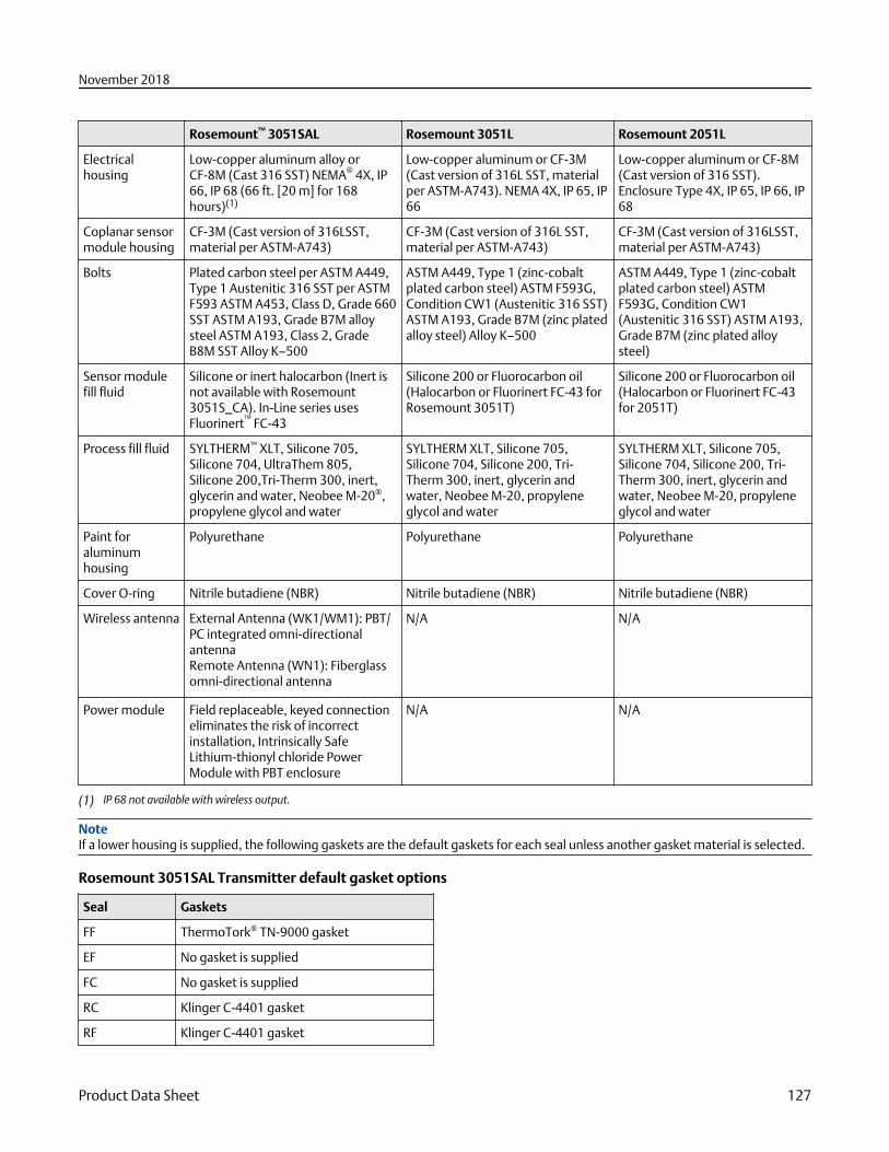
Rosemount™ 3051SAL Rosemount 3051L Rosemount 2051L
Electricalhousing
Low-copper aluminum alloy orCF-8M (Cast 316 SST) NEMA® 4X, IP66, IP 68 (66 ft. [20 m] for 168hours)(1)
Low-copper aluminum or CF-3M(Cast version of 316L SST, materialper ASTM-A743). NEMA 4X, IP 65, IP66
Low-copper aluminum or CF-8M(Cast version of 316 SST).Enclosure Type 4X, IP 65, IP 66, IP68
Coplanar sensormodule housing
CF-3M (Cast version of 316LSST,material per ASTM-A743)
CF-3M (Cast version of 316L SST,material per ASTM-A743)
CF-3M (Cast version of 316LSST,material per ASTM-A743)
Bolts Plated carbon steel per ASTM A449,Type 1 Austenitic 316 SST per ASTMF593 ASTM A453, Class D, Grade 660SST ASTM A193, Grade B7M alloysteel ASTM A193, Class 2, GradeB8M SST Alloy K–500
ASTM A449, Type 1 (zinc-cobaltplated carbon steel) ASTM F593G,Condition CW1 (Austenitic 316 SST)ASTM A193, Grade B7M (zinc platedalloy steel) Alloy K–500
ASTM A449, Type 1 (zinc-cobaltplated carbon steel) ASTMF593G, Condition CW1(Austenitic 316 SST) ASTM A193,Grade B7M (zinc plated alloysteel)
Sensor modulefill fluid
Silicone or inert halocarbon (Inert isnot available with Rosemount3051S_CA). In-Line series usesFluorinert™ FC-43
Silicone 200 or Fluorocarbon oil(Halocarbon or Fluorinert FC-43 forRosemount 3051T)
Silicone 200 or Fluorocarbon oil(Halocarbon or Fluorinert FC-43for 2051T)
Process fill fluid SYLTHERM™ XLT, Silicone 705,Silicone 704, UltraThem 805,Silicone 200,Tri-Therm 300, inert,glycerin and water, Neobee M-20®,propylene glycol and water
SYLTHERM XLT, Silicone 705,Silicone 704, Silicone 200, Tri-Therm 300, inert, glycerin andwater, Neobee M-20, propyleneglycol and water
SYLTHERM XLT, Silicone 705,Silicone 704, Silicone 200, Tri-Therm 300, inert, glycerin andwater, Neobee M-20, propyleneglycol and water
Paint foraluminumhousing
Polyurethane Polyurethane Polyurethane
Cover O-ring Nitrile butadiene (NBR) Nitrile butadiene (NBR) Nitrile butadiene (NBR)
Wireless antenna External Antenna (WK1/WM1): PBT/PC integrated omni-directionalantennaRemote Antenna (WN1): Fiberglassomni-directional antenna
N/A N/A
Power module Field replaceable, keyed connectioneliminates the risk of incorrectinstallation, Intrinsically SafeLithium-thionyl chloride PowerModule with PBT enclosure
N/A N/A
(1) IP 68 not available with wireless output.
NoteIf a lower housing is supplied, the following gaskets are the default gaskets for each seal unless another gasket material is selected.
Rosemount 3051SAL Transmitter default gasket options
Seal Gaskets
FF ThermoTork® TN-9000 gasket
EF No gasket is supplied
FC No gasket is supplied
RC Klinger C-4401 gasket
RF Klinger C-4401 gasket
November 2018
Product Data Sheet 127
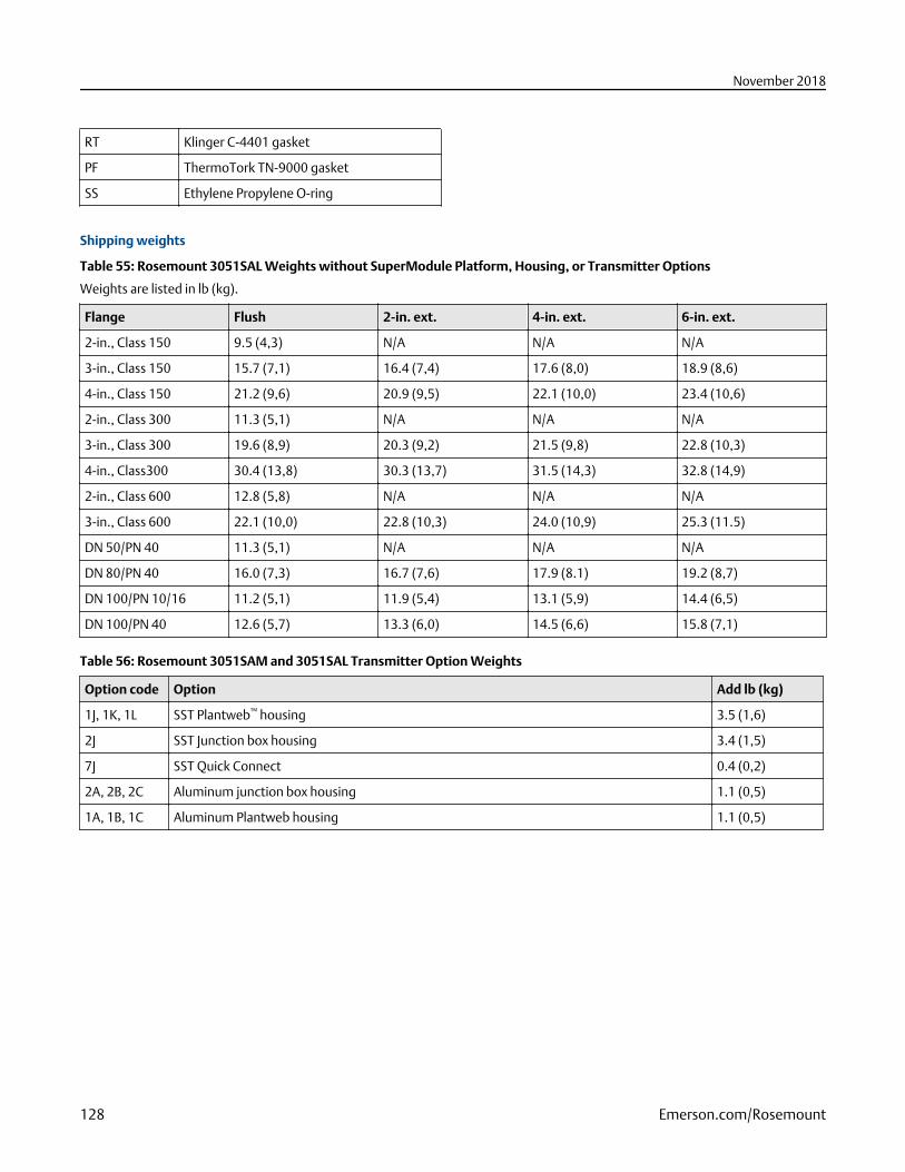
RT Klinger C-4401 gasket
PF ThermoTork TN-9000 gasket
SS Ethylene Propylene O-ring
Shipping weights
Table 55: Rosemount 3051SAL Weights without SuperModule Platform, Housing, or Transmitter Options
Weights are listed in lb (kg).
Flange Flush 2-in. ext. 4-in. ext. 6-in. ext.
2-in., Class 150 9.5 (4,3) N/A N/A N/A
3-in., Class 150 15.7 (7,1) 16.4 (7,4) 17.6 (8,0) 18.9 (8,6)
4-in., Class 150 21.2 (9,6) 20.9 (9,5) 22.1 (10,0) 23.4 (10,6)
2-in., Class 300 11.3 (5,1) N/A N/A N/A
3-in., Class 300 19.6 (8,9) 20.3 (9,2) 21.5 (9,8) 22.8 (10,3)
4-in., Class300 30.4 (13,8) 30.3 (13,7) 31.5 (14,3) 32.8 (14,9)
2-in., Class 600 12.8 (5,8) N/A N/A N/A
3-in., Class 600 22.1 (10,0) 22.8 (10,3) 24.0 (10,9) 25.3 (11.5)
DN 50/PN 40 11.3 (5,1) N/A N/A N/A
DN 80/PN 40 16.0 (7,3) 16.7 (7,6) 17.9 (8.1) 19.2 (8,7)
DN 100/PN 10/16 11.2 (5,1) 11.9 (5,4) 13.1 (5,9) 14.4 (6,5)
DN 100/PN 40 12.6 (5,7) 13.3 (6,0) 14.5 (6,6) 15.8 (7,1)
Table 56: Rosemount 3051SAM and 3051SAL Transmitter Option Weights
Option code Option Add lb (kg)
1J, 1K, 1L SST Plantweb™ housing 3.5 (1,6)
2J SST Junction box housing 3.4 (1,5)
7J SST Quick Connect 0.4 (0,2)
2A, 2B, 2C Aluminum junction box housing 1.1 (0,5)
1A, 1B, 1C Aluminum Plantweb housing 1.1 (0,5)
November 2018
128 Emerson.com/Rosemount
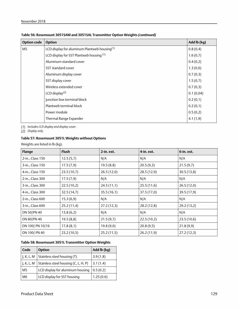
Table 56: Rosemount 3051SAM and 3051SAL Transmitter Option Weights (continued)
Option code Option Add lb (kg)
M5 LCD display for aluminum Plantweb housing(1)
LCD display for SST Plantweb housing (1)
Aluminum standard cover
SST standard cover
Aluminum display cover
SST display cover
Wireless extended cover
LCD display(2)
Junction box terminal block
Plantweb terminal block
Power module
Thermal Range Expander
0.8 (0,4)
1.6 (0,7)
0.4 (0,2)
1.3 (0,6)
0.7 (0,3)
1.5 (0,7)
0.7 (0,3)
0.1 (0,04)
0.2 (0,1)
0.2 (0,1)
0.5 (0,2)
4.1 (1,9)
(1) Includes LCD display and display cover.(2) Display only.
Table 57: Rosemount 3051L Weights without Options
Weights are listed in lb (kg).
Flange Flush 2-in. ext. 4-in. ext. 6-in. ext.
2-in., Class 150 12.5 (5,7) N/A N/A N/A
3-in., Class 150 17.5 (7,9) 19.5 (8,8) 20.5 (9,3) 21.5 (9,7)
4-in., Class 150 23.5 (10,7) 26.5 (12,0) 28.5 (12,9) 30.5 (13,8)
2-in., Class 300 17.5 (7,9) N/A N/A N/A
3-in., Class 300 22.5 (10,2) 24.5 (11,1) 25.5 (11,6) 26.5 (12,0)
4-in., Class 300 32.5 (14,7) 35.5 (16,1) 37.5 (17,0) 39.5 (17,9)
2-in., Class 600 15.3 (6,9) N/A N/A N/A
3-in., Class 600 25.2 (11,4) 27.2 (12,3) 28.2 (12,8) 29.2 (13,2)
DN 50/PN 40 13.8 (6,2) N/A N/A N/A
DN 80/PN 40 19.5 (8,8) 21.5 (9,7) 22.5 (10,2) 23.5 (10,6)
DN 100/ PN 10/16 17.8 (8,1) 19.8 (9,0) 20.8 (9,5) 21.8 (9,9)
DN 100/ PN 40 23.2 (10,5) 25.2 (11,5) 26.2 (11,9) 27.2 (12,3)
Table 58: Rosemount 3051L Transmitter Option Weights
Code Option Add lb (kg)
J, K, L, M Stainless steel housing (T) 3.9 (1.8)
J, K, L, M Stainless steel housing (C, L, H, P) 3.1 (1.4)
M5 LCD display for aluminum housing 0.5 (0.2)
M6 LCD display for SST housing 1.25 (0.6)
November 2018
Product Data Sheet 129
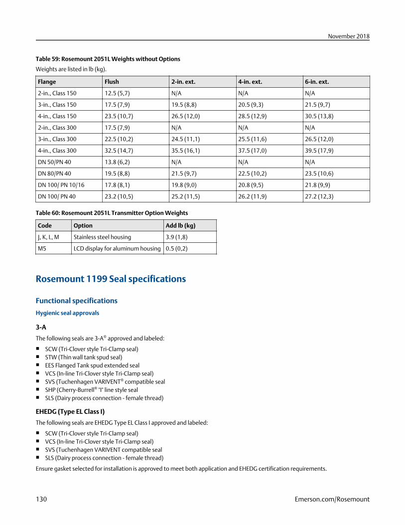
Table 59: Rosemount 2051L Weights without Options
Weights are listed in lb (kg).
Flange Flush 2-in. ext. 4-in. ext. 6-in. ext.
2-in., Class 150 12.5 (5,7) N/A N/A N/A
3-in., Class 150 17.5 (7,9) 19.5 (8,8) 20.5 (9,3) 21.5 (9,7)
4-in., Class 150 23.5 (10,7) 26.5 (12,0) 28.5 (12,9) 30.5 (13,8)
2-in., Class 300 17.5 (7,9) N/A N/A N/A
3-in., Class 300 22.5 (10,2) 24.5 (11,1) 25.5 (11,6) 26.5 (12,0)
4-in., Class 300 32.5 (14,7) 35.5 (16,1) 37.5 (17,0) 39.5 (17,9)
DN 50/PN 40 13.8 (6,2) N/A N/A N/A
DN 80/PN 40 19.5 (8,8) 21.5 (9,7) 22.5 (10,2) 23.5 (10,6)
DN 100/ PN 10/16 17.8 (8,1) 19.8 (9,0) 20.8 (9,5) 21.8 (9,9)
DN 100/ PN 40 23.2 (10,5) 25.2 (11,5) 26.2 (11,9) 27.2 (12,3)
Table 60: Rosemount 2051L Transmitter Option Weights
Code Option Add lb (kg)
J, K, L, M Stainless steel housing 3.9 (1,8)
M5 LCD display for aluminum housing 0.5 (0,2)
Rosemount 1199 Seal specifications
Functional specifications
Hygienic seal approvals
3-A
The following seals are 3-A® approved and labeled:
■ SCW (Tri-Clover style Tri-Clamp seal)■ STW (Thin wall tank spud seal)■ EES Flanged Tank spud extended seal■ VCS (In-line Tri-Clover style Tri-Clamp seal)■ SVS (Tuchenhagen VARIVENT® compatible seal■ SHP (Cherry-Burrell® "I" line style seal■ SLS (Dairy process connection - female thread)
EHEDG (Type EL Class I)
The following seals are EHEDG Type EL Class I approved and labeled:
■ SCW (Tri-Clover style Tri-Clamp seal)■ VCS (In-line Tri-Clover style Tri-Clamp seal)■ SVS (Tuchenhagen VARIVENT compatible seal■ SLS (Dairy process connection - female thread)
Ensure gasket selected for installation is approved to meet both application and EHEDG certification requirements.
November 2018
130 Emerson.com/Rosemount
Hygienic fill fluids
The hygienic fill fluids glycerin and water and Propylene Glycol and water meet United States Pharmacopeia(USP) and FoodChemical Codex (FCC) requirements and is Generally Recognized as Safe (GRAS) in accordance with the FDA Code of FederalRegulations Title 21. The hygienic fill fluid Neobee M-20 is approved under 21CFR 172.856 as a direct food additive and under 21CFR 174.5 as an indirect food additive. Tri-Therm 300 is registered by NSF as meeting FDA 21 CFR regulatory requirements and isacceptable for use where there is possibility of incidental food contact (HT 1).
Hygienic O-rings
The EPDM, Fluorocarbon (FMK), and Nitrilebutadiene (NBR) O-rings for the SSW Tank Spud Seal meet 3-A Hygienic StandardNumber 18 Class 1 requirements. The EPDM O-ring also meets USP Class VI approval requirements.
Transmissible Spongiform Encephalopathy (TSE) Declaration
Emerson certifies no process wetted components used in hygienic seal products contain substances of animal origin. Materialsused in the production or processing of wetted components for hygienic seals meet the requirements stated in EMA/410/01 Rev. 3and ISO 22442-1:2015. Wetted components in hygienic seals are considered free of TSE.
Surface finish certification (Q16 option)
When ordering the Q16 option in the pressure transmitter model number, the surface finish of the seal diaphragm is certified perBPE 2002 requirements. This surface finish certification is available for Tri Clamp, Tri Clamp Inline, Tank Spud, and Thin Wall TankSpud seal types.
NACE Standard (Q15 or Q25 option)
NACE (National Association of Corrosion Engineers) standard MR0175/ISO 15156 defines metallic material requirements forresistance to sulfide stress cracking when applied on petroleum production, drilling, gathering and flow line equipment, and fieldprocessing facilities to be used in H2S bearing hydrocarbon service. MR0103 provides material requirements exclusive to sourpetroleum refining environments. Compliance guidelines are intended to include “wetted” materials as recommended by bothNACE standards. The option code T in several of the general purpose seal types limits the wetted material offering. Metallurgicalrequirements for alloys used are virtually identical for the two standards, but application conditions enforced are different and canlimit material acceptance. Contact an Emerson representative to aid in selecting the proper materials to meet the NACE standard.
Material traceability (Q8 Option)
Material traceability is provided for the seal, upper housing, and if applicable, lower housing/flushing connection or diaphragmextension, upon selecting the option code Q8 in the pressure transmitter model number. Material traceability for the transmitter/seal system is provided per the DIN EN10204 3.1 standard, and is only available for general purpose seal types.
Performance specificationsFor zero-based spans, reference conditions, silicone oil fill, glass-filled PTFE O-rings, SST materials, coplanar flange (Rosemount3051SMV, 3051S_C) or ½–14 NPT (Rosemount 3051S_T) process connections, digital trim values set to equal range points.
Remote seal system performance calculation report (QZ Option)
Instrument Toolkit™ calculates the remote seal system performance and validates model number configuration.
When the QZ option code is specified within the pressure transmitter model structure, Emerson will generate a remote seal systemcalculation report for the given application. This report quantifies all aspects of remote seal system performance including sealtemperature effects, head temperature effects, seal response time, and transmitter total probable error.
Physical specifications
Material selection
Emerson™ provides a variety of Rosemount™ products with various product options and configurations including materials ofconstruction that can be expected to perform well in a wide range of applications. The Rosemount product information presentedis intended as a guide for the purchaser to make an appropriate selection for the application. It is the purchaser’s sole responsibilityto make a careful analysis of all process parameters (such as all chemical components, temperature, pressure, flow rate, abrasives,contaminants, etc.), when specifying product, materials, options and components for the particular application. Emerson is not in aposition to evaluate or guarantee the compatibility of the process fluid or other process parameters with the product, options,configuration or materials of construction selected.
November 2018
Product Data Sheet 131
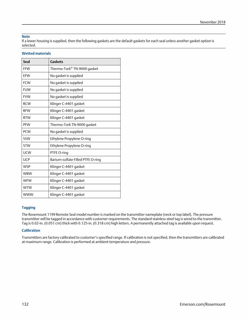
NoteIf a lower housing is supplied, then the following gaskets are the default gaskets for each seal unless another gasket option isselected.
Wetted materials
Seal Gaskets
FFW Thermo-Tork® TN-9000 gasket
EFW No gasket is supplied
FCW No gasket is supplied
FUW No gasket is supplied
FVW No gasket is supplied
RCW Klinger C-4401 gasket
RFW Klinger C-4401 gasket
RTW Klinger C-4401 gasket
PFW Thermo-Tork TN-9000 gasket
PCW No gasket is supplied
SSW Ethylene Propylene O-ring
STW Ethylene Propylene O-ring
UCW PTFE O-ring
UCP Barium-sulfate Filled PTFE O-ring
WSP Klinger C-4401 gasket
WBW Klinger C-4401 gasket
WFW Klinger C-4401 gasket
WTW Klinger C-4401 gasket
WWW Klinger C-4401 gasket
Tagging
The Rosemount 1199 Remote Seal model number is marked on the transmitter nameplate (neck or top label). The pressuretransmitter will be tagged in accordance with customer requirements. The standard stainless steel tag is wired to the transmitter.Tag is 0.02-in. (0.051 cm) thick with 0.125-in. (0.318 cm) high letters. A permanently attached tag is available upon request.
Calibration
Transmitters are factory calibrated to customer’s specified range. If calibration is not specified, then the transmitters are calibratedat maximum range. Calibration is performed at ambient temperature and pressure.
November 2018
132 Emerson.com/Rosemount
Product certifications
Rosemount 3051S/3051SFx/3051S-ERSRev 2.2
European Directive Information
A copy of the EU Declaration of Conformity can be found at the end of the Quick Start Guide. The most recent revision of the EUDeclaration of Conformity can be found at Emerson.com/Rosemount.
Ordinary Location Certification
As standard, the transmitter has been examined and tested to determine that the design meets the basic electrical, mechanical,and fire protection requirements by a nationally recognized test laboratory (NRTL) as accredited by the Federal Occupational Safetyand Health Administration (OSHA).
Installing Equipment in North America
The US National Electrical Code® (NEC) and the Canadian Electrical Code (CEC) permit the use of Division marked equipment inZones and Zone marked equipment in Divisions. The markings must be suitable for the area classification, gas, and temperatureclass. This information is clearly defined in the respective codes.
USA
E5 US Explosionproof (XP) and Dust-Ignitionproof (DIP)
Certificate FM16US0090
Standards FM Class 3600 - 2011, FM Class 3615 - 2006, FM Class 3616 - 2011, FM Class 3810 - 2005, ANSI/NEMA 250 - 2003
Markings XP CL I, DIV 1, GP B, C, D; DIP CL II, DIV 1, GP E, F, G; CL III; T5(–50 °C ≤ Ta ≤ +85 °C); Factory Sealed; Type 4X
I5 US Intrinsic Safety (IS) and Nonincendive (NI)
Certificate FM16US0089X
Standards FM Class 3600 - 2011, FM Class 3610 - 2010, FM Class 3611 - 2004, FM Class 3810 - 2005, NEMA® 250 - 2003
Markings IS CL I, DIV 1, GP A, B, C, D; CL II, DIV 1, GP E, F, G; Class III; Class 1, Zone 0 AEx ia IIC T4; NI CL 1, DIV 2, GP A, B, C, D;T4(–50 °C ≤ Ta ≤ +70 °C) [HART]; T4(–50 °C ≤ Ta ≤ +60 °C) [Fieldbus]; when connected per Rosemount drawing03151-1006; Type 4X
Special Condition for Safe Use:
1. The Model 3051S/3051S-ERS Pressure Transmitter contains aluminum and is considered to constitute a potential risk ofignition by impact or friction. Care must be taken into account during installation and use to prevent impact and friction.
NoteTransmitters marked with NI CL 1, DIV 2 can be installed in Division 2 locations using general Division 2 wiring methods orNonincendive Field Wiring (NIFW). See Drawing 03151-1006.
IE US FISCO Intrinsically Safe
Certificate FM16US0089X
Standards FM Class 3600 - 2011, FM Class 3610 - 2010, FM Class 3611 - 2004, FM Class 3810 - 2005, NEMA 250 - 2003
Markings IS CL I, DIV 1, GP A, B, C, D; T4(–50 °C ≤ Ta ≤ +60 °C); when connected per Rosemount drawing 03151-1006; Type 4X
November 2018
Product Data Sheet 133
Special Condition for Safe Use:
1. The Rosemount 3051S/3051S-ERS Pressure Transmitter contains aluminum and is considered to constitute a potential riskof ignition by impact or friction. Care must be taken into account during installation and use to prevent impact and friction.
Canada
E6 Canada Explosionproof, Dust-Ignitionproof, and Division 2
Certificate 1143113
Standards CAN/CSA C22.2 No. 0-10, CSA Std C22.2 No. 25-1966, CSA Std C22.2 No. 30-M1986, CAN/CSA C22.2 No. 94-M91,CSA Std C22.2 No. 142-M1987, CSA Std C22.2 No. 213-M1987, ANSI/ISA 12.27.01-2003, CSA Std C22.2 No.60529:05
Markings Explosionproof Class I, Division 1, Groups B, C, D; Dust-Ignitionproof Class II, Division 1, Groups E, F, G; Class III;suitable for Class I, Zone 1, Group IIB+H2, T5; suitable for Class I, Division 2, Groups A, B, C, D; suitable for Class I,Zone 2, Group IIC, T5; when connected per Rosemount drawing 03151-1013; Type 4X
I6 Canada Intrinsically Safe
Certificate 1143113
Standards CAN/CSA C22.2 No. 0-10, CSA Std C22.2 No. 25-1966, CSA Std C22.2 No. 30-M1986, CAN/CSA C22.2 No. 94-M91,CSA Std C22.2 No. 142-M1987, CSA Std C22.2 No. 157-92, ANSI/ISA 12.27.01-2003, CSA Std C22.2 No. 60529:05
Markings Intrinsically Safe Class I, Division 1; Groups A, B, C, D; suitable for Class 1, Zone 0, IIC, T3C; when connected perRosemount drawing 03151-1016 [3051S] 03151-1313 [ERS]; Type 4X
IF Canada FISCO
Certificate 1143113
Standards CAN/CSA C22.2 No. 0-10, CSA Std C22.2 No. 30-M1986, CAN/CSA C22.2 No. 94-M91, CSA Std C22.2 No. 142-M1987, CSA Std C22.2 No. 157-92, ANSI/ISA 12.27.01-2003, CSA Std C22.2 No. 60529:05
Markings FISCO Intrinsically Safe Class I, Division 1; Groups A, B, C, D; suitable for Class 1, Zone 0, IIC, T3C; when connected perRosemount drawing 03151-1016 [3051S] 03151-1313 [ERS]; Type 4X
Europe
E1 ATEX Flameproof
Certificate KEMA 00ATEX2143X
Standards EN 60079-0:2012+A11:2013, EN 60079-1:2014, EN 60079-26:2015
Markings II 1/2 G Ex db IIC T6…T4 Ga/Gb, T6(–60 °C ≤ Ta ≤ +70 °C), T5/T4(–60 °C ≤ Ta ≤ +80 °C)
Table 61: Process Temperature
Temperature class Process temperature
T6 –60 °C to +70 °C
T5 –60 °C to +80 °C
T4 –60 °C to +120 °C
Special Conditions for Safe Use (X):
1. This device contains a thin wall diaphragm less than 1 mm thickness that forms a boundary between Category 1 (processconnection) and Category 2 (all other parts of the equipment). The model code and datasheet are to be consulted fordetails of the diaphragm material. Installation, maintenance and use shall take into account the environmental conditions
November 2018
134 Emerson.com/Rosemount
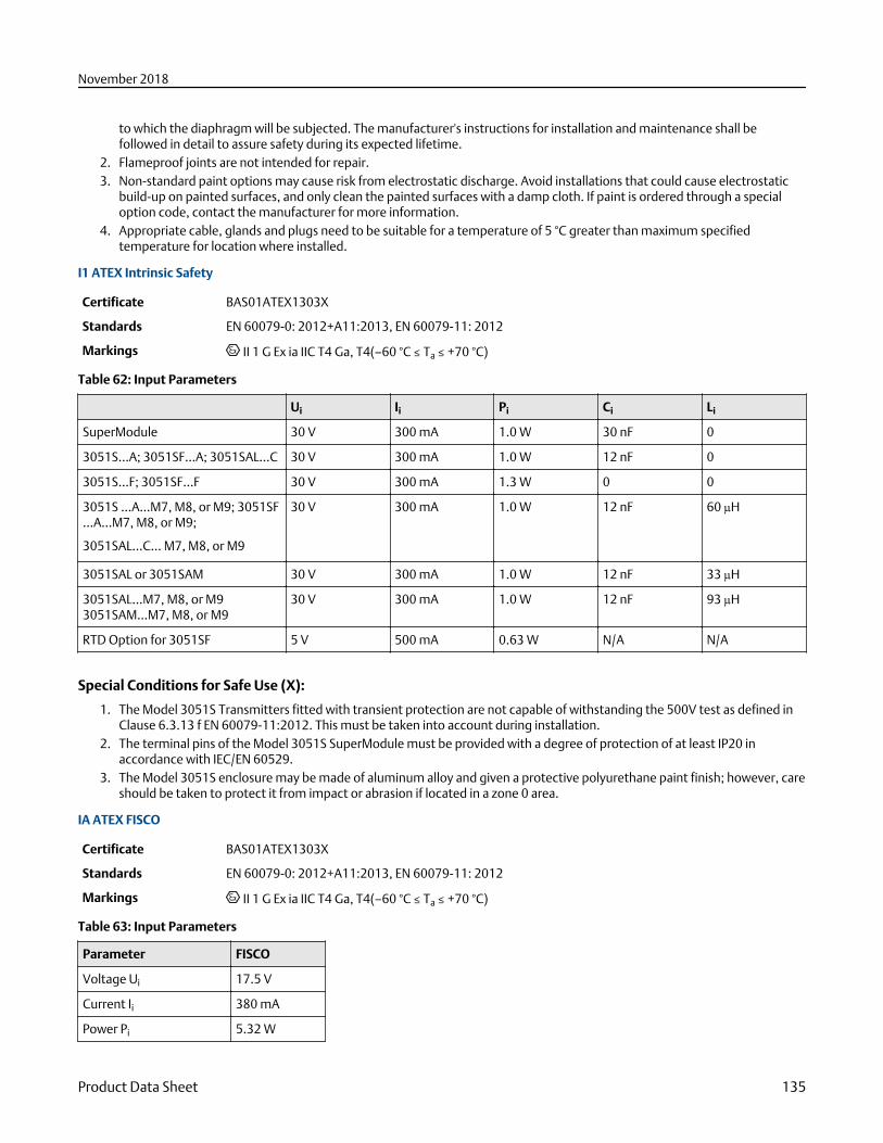
to which the diaphragm will be subjected. The manufacturer's instructions for installation and maintenance shall befollowed in detail to assure safety during its expected lifetime.
2. Flameproof joints are not intended for repair.3. Non-standard paint options may cause risk from electrostatic discharge. Avoid installations that could cause electrostatic
build-up on painted surfaces, and only clean the painted surfaces with a damp cloth. If paint is ordered through a specialoption code, contact the manufacturer for more information.
4. Appropriate cable, glands and plugs need to be suitable for a temperature of 5 °C greater than maximum specifiedtemperature for location where installed.
I1 ATEX Intrinsic Safety
Certificate BAS01ATEX1303X
Standards EN 60079-0: 2012+A11:2013, EN 60079-11: 2012
Markings II 1 G Ex ia IIC T4 Ga, T4(–60 °C ≤ Ta ≤ +70 °C)
Table 62: Input Parameters
Ui Ii Pi Ci Li
SuperModule 30 V 300 mA 1.0 W 30 nF 0
3051S...A; 3051SF…A; 3051SAL…C 30 V 300 mA 1.0 W 12 nF 0
3051S…F; 3051SF…F 30 V 300 mA 1.3 W 0 0
3051S …A…M7, M8, or M9; 3051SF…A…M7, M8, or M9;
3051SAL…C… M7, M8, or M9
30 V 300 mA 1.0 W 12 nF 60 µH
3051SAL or 3051SAM 30 V 300 mA 1.0 W 12 nF 33 µH
3051SAL…M7, M8, or M93051SAM…M7, M8, or M9
30 V 300 mA 1.0 W 12 nF 93 µH
RTD Option for 3051SF 5 V 500 mA 0.63 W N/A N/A
Special Conditions for Safe Use (X):
1. The Model 3051S Transmitters fitted with transient protection are not capable of withstanding the 500V test as defined inClause 6.3.13 f EN 60079-11:2012. This must be taken into account during installation.
2. The terminal pins of the Model 3051S SuperModule must be provided with a degree of protection of at least IP20 inaccordance with IEC/EN 60529.
3. The Model 3051S enclosure may be made of aluminum alloy and given a protective polyurethane paint finish; however, careshould be taken to protect it from impact or abrasion if located in a zone 0 area.
IA ATEX FISCO
Certificate BAS01ATEX1303X
Standards EN 60079-0: 2012+A11:2013, EN 60079-11: 2012
Markings II 1 G Ex ia IIC T4 Ga, T4(–60 °C ≤ Ta ≤ +70 °C)
Table 63: Input Parameters
Parameter FISCO
Voltage Ui 17.5 V
Current Ii 380 mA
Power Pi 5.32 W
November 2018
Product Data Sheet 135
Table 63: Input Parameters (continued)
Capacitance Ci 0
Inductance Li 0
Special Conditions for Safe Use (X):
1. The Model 3051S Transmitters fitted with transient protection are not capable of withstanding the 500 V test as defined inClause 6.3.13 of EN 60079-11:2012. This must be taken into account during installation.
2. The terminal pins of the Model 3051S SuperModule must be provided with a degree of protection of at least IP20 inaccordance with IEC/EN 60529.
3. The Model 3051S enclosure may be made of aluminum alloy and given a protective polyurethane paint finish; however, careshould be taken to protect it from impact or abrasion if located in a zone 0 area.
ND ATEX Dust
Certificate BAS01ATEX1374X
Standards EN 60079-0: 2012+A11:2013, EN 60079-31: 2009
Markings II 1 D Ex ta IIIC T105 °C T 500 95 °C Da, (–20 °C ≤ T a ≤ +85 °C), Vmax = 42.4 V
Special Conditions for Safe Use (X):
1. Cable entries must be used which maintain the ingress protection of the enclosure to at least IP66.2. Unused cable entries must be filled with suitable blanking plugs which maintain the ingress protection of the enclosure to at
least IP66.3. Cable entries and blanking plugs must be suitable for the ambient temperature range of the apparatus and capable of
withstanding a 7J impact test.4. The SuperModule(s) must be securely screwed in place to maintain the ingress protection of the enclosure(s).
N1 ATEX Type n
Certificate BAS01ATEX3304X
Standards EN 60079-0: 2012+A11:2013, EN 60079-15: 2010
Markings II 3 G Ex nA IIC T5 Gc, (–40 °C ≤ Ta ≤ +85 °C), Vmax = 45 V
Special Condition for Safe Use (X):
1. The equipment is not capable of withstanding the 500 V insulation test required by clause 6.5 of EN 60079-15:2010. Thismust be taken into account when installing the equipment.
NoteRTD Assembly is not included with the 3051SFx Type n Approval.
International
E7 IECEx Flameproof and Dust
Certificate IECEx KEM 08.0010X (Flameproof)
Standards IEC 60079-0:2011, IEC 60079-1:2014, IEC 60079-26:2014
Markings Ex db IIC T6…T4 Ga/Gb, T6(–60 °C ≤ Ta ≤ +70 °C), T5/T4(–60 °C ≤ Ta ≤ +80 °C)
Table 64: Process Temperature
Temperature class Process temperature
T6 –60 °C to +70 °C
November 2018
136 Emerson.com/Rosemount
Table 64: Process Temperature (continued)
Temperature class Process temperature
T5 –60 °C to +80 °C
T4 –60 °C to +120 °C
Special Conditions for Safe Use (X):
1. This device contains a thin wall diaphragm less than 1 mm thickness that forms a boundary between EPL Ga (processconnection) and EPL Gb (all other parts of the equipment). The model code and datasheet are to be consulted for details ofthe diaphragm material. Installation, maintenance and use shall take into account the environmental conditions to whichthe diaphragm will be subjected. The manufacturer's instructions for installation and maintenance shall be followed in detailto assure safety during its expected lifetime.
2. Flameproof joints are not intended for repair.3. Non-standard paint options may cause risk from electrostatic discharge. Avoid installations that could cause electrostatic
buildup on painted surfaces, and only clean the painted surfaces with a damp cloth. If paint is ordered through a specialoption code, contact the manufacturer for more information.
4. Appropriate cable, glands and plugs need to be suitable for a temperature of 5 °C greater than maximum specifiedtemperature for location where installed.
Certificate IECEx BAS 09.0014X (Dust)
Standards IEC 60079-0:2011, IEC 60079-31:2008
Markings Ex ta IIIC T105 °C T50095 °C Da, (–20 °C ≤ Ta ≤ +85 °C), Vmax = 42.4 V
Special Conditions for Safe Use (X):
1. Cable entries must be used which maintain the ingress protection of the enclosure to at least IP66.2. Unused cable entries must be filled with suitable blanking plugs which maintain the ingress protection of the enclosure to at
least IP66.3. Cable entries and blanking plugs must be suitable for the ambient temperature range of the apparatus and capable of
withstanding a 7J impact test.4. The 3051S- SuperModule must be securely screwed in place to maintain the ingress protection of the enclosure.
I7 IECEx Intrinsic Safety
Certificate IECEx BAS 04.0017X
Standards IEC 60079-0: 2011, IEC 60079-11: 2011
Markings Ex ia IIC T4 Ga, T4(–60 °C ≤ Ta ≤ +70 °C)
Table 65: Input Parameters
Ui Ii Pi Ci Li
SuperModule 30 V 300 mA 1.0 W 30 nF 0
3051S...A; 3051SF…A; 3051SAL…C 30 V 300 mA 1.0 W 12 nF 0
3051S…F; 3051SF…F 30 V 300 mA 1.3 W 0 0
3051S …A…M7, M8, or M9; 3051SF…A…M7, M8, or M9;
3051SAL…C… M7, M8, or M9
30 V 300 mA 1.0 W 12 nF 60 µH
3051SAL or 3051SAM 30 V 300 mA 1.0 W 12 nF 33 µH
3051SAL…M7, M8, or M93051SAM…M7, M8, or M9
30 V 300 mA 1.0 W 12 nF 93 µH
November 2018
Product Data Sheet 137
Table 65: Input Parameters (continued)
Ui Ii Pi Ci Li
RTD Option for 3051SF 5 V 500 mA 0.63 W N/A N/A
Special Conditions for Safe Use (X):
1. The Model 3051S Transmitters fitted with transient protection are not capable of withstanding the 500 V test as defined inClause 6.3.13 of EN 60079-11:2012. This must be taken into account during installation.
2. The terminal pins of the Model 3051S SuperModule must be provided with a degree of protection of at least IP20 inaccordance with IEC/EN 60529.
3. The Model 3051S enclosure may be made of aluminum alloy and given a protective polyurethane paint finish; however, careshould be taken to protect it from impact or abrasion if located in a zone 0 area.
I7 IECEx Intrinsic Safety - Group I - Mining (I7 with Special A0259)
Certificate IECEx TSA 14.0019X
Standards IEC 60079-0: 2011, IEC 60079-11: 2011
Markings Ex ia I Ma (–60 °C ≤ Ta ≤ +70 °C)
Table 66: Input Parameters
Ui Ii Pi Ci Li
SuperModule 30 V 300 mA 1.0 W 30 nF 0
3051S...A; 3051SF…A; 3051SAL…C 30 V 300 mA 1.0 W 12 nF 0
3051S…F; 3051SF…F 30 V 300 mA 1.3 W 0 0
3051S …A…M7, M8, or M9; 3051SF…A…M7, M8, or M9;
3051SAL…C… M7, M8, or M9
30 V 300 mA 1.0 W 12 nF 60 µH
3051SAL or 3051SAM 30 V 300 mA 1.0 W 12 nF 33 µH
3051SAL…M7, M8, or M93051SAM…M7, M8, or M9
30 V 300 mA 1.0 W 12 nF 93 µH
RTD Option for 3051SF 5 V 500 mA 0.63 W N/A N/A
Special Conditions for Safe Use (X):
1. If the apparatus is fitted with optional 90 V transient suppressor, it is not capable of withstanding the 500 V insulation testrequired by Clause 6.3.13 of IEC60079-11. This must be taken into account when installing the apparatus.
2. It is a condition of safe use that the above input parameters shall be taken into account during installation.3. It is a condition of manufacture that only the apparatus fitted with housing, covers and sensor module housing made out of
stainless steel are used in Group I applications.
IG IECEx FISCO
Certificate IECEx BAS 04.0017X
Standards IEC 60079-0: 2011, IEC 60079-11: 2011
Markings Ex ia IIC T4 Ga, T4(–60 °C ≤ Ta ≤ +70 °C)
November 2018
138 Emerson.com/Rosemount
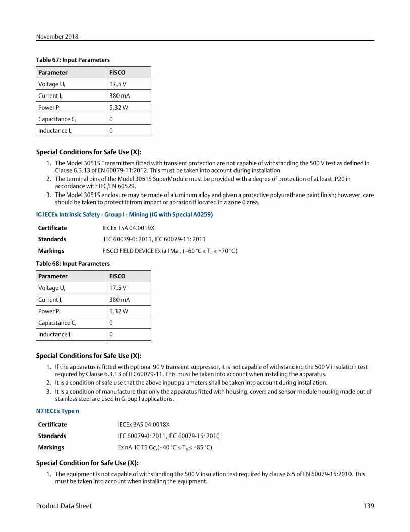
Table 67: Input Parameters
Parameter FISCO
Voltage Ui 17.5 V
Current Ii 380 mA
Power Pi 5.32 W
Capacitance Ci 0
Inductance Li 0
Special Conditions for Safe Use (X):
1. The Model 3051S Transmitters fitted with transient protection are not capable of withstanding the 500 V test as defined inClause 6.3.13 of EN 60079-11:2012. This must be taken into account during installation.
2. The terminal pins of the Model 3051S SuperModule must be provided with a degree of protection of at least IP20 inaccordance with IEC/EN 60529.
3. The Model 3051S enclosure may be made of aluminum alloy and given a protective polyurethane paint finish; however, careshould be taken to protect it from impact or abrasion if located in a zone 0 area.
IG IECEx Intrinsic Safety - Group I - Mining (IG with Special A0259)
Certificate IECEx TSA 04.0019X
Standards IEC 60079-0: 2011, IEC 60079-11: 2011
Markings FISCO FIELD DEVICE Ex ia I Ma , (–60 °C ≤ Ta ≤ +70 °C)
Table 68: Input Parameters
Parameter FISCO
Voltage Ui 17.5 V
Current Ii 380 mA
Power Pi 5.32 W
Capacitance Ci 0
Inductance Li 0
Special Conditions for Safe Use (X):
1. If the apparatus is fitted with optional 90 V transient suppressor, it is not capable of withstanding the 500 V insulation testrequired by Clause 6.3.13 of IEC60079-11. This must be taken into account when installing the apparatus.
2. It is a condition of safe use that the above input parameters shall be taken into account during installation.3. It is a condition of manufacture that only the apparatus fitted with housing, covers and sensor module housing made out of
stainless steel are used in Group I applications.
N7 IECEx Type n
Certificate IECEx BAS 04.0018X
Standards IEC 60079-0: 2011, IEC 60079-15: 2010
Markings Ex nA IIC T5 Gc,(–40 °C ≤ Ta ≤ +85 °C)
Special Condition for Safe Use (X):
1. The equipment is not capable of withstanding the 500 V insulation test required by clause 6.5 of EN 60079-15:2010. Thismust be taken into account when installing the equipment.
November 2018
Product Data Sheet 139
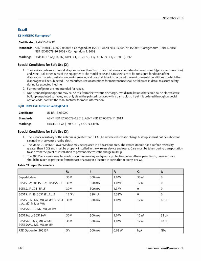
Brazil
E2 INMETRO Flameproof
Certificate UL-BR15.0393X
Standards ABNT NBR IEC 60079-0:2008 + Corrigendum 1:2011, ABNT NBR IEC 60079-1:2009 + Corrigendum 1:2011, ABNTNBR IEC 60079-26:2008 + Corrigendum 1: 2008
Markings Ex db IIC T* Ga/Gb, T6(–60 °C ≤ Ta ≤ +70 °C), T5/T4(–60 °C ≤ Ta ≤ +80 °C), IP66
Special Conditions for Safe Use (X):
1. The device contains a thin wall diaphragm less than 1mm thick that forms a boundary between zone 0 (process connection)and zone 1 (all other parts of the equipment).The model code and datasheet are to be consulted for details of thediaphragm material. Installation, maintenance, and use shall take into account the environmental conditions to which thediaphragm will be subjected. The manufacturer's instructions for maintenance shall be followed in detail to assure safetyduring its expected lifetime.
2. Flameproof joints are not intended for repair.3. Non-standard paint options may cause risk from electrostatic discharge. Avoid installations that could cause electrostatic
buildup on painted surfaces, and only clean the painted surfaces with a damp cloth. If paint is ordered through a specialoption code, contact the manufacturer for more information.
I2/IB INMETRO Intrinsic Safety/FISCO
Certificate UL-BR 15.0392X
Standards ABNT NBR IEC 60079-0:2013, ABNT NBR IEC 60079-11:2013
Markings Ex ia IIC T4 Ga (–60 °C ≤ Ta ≤ +70 °C), IP66
Special Conditions for Safe Use (X):
1. The surface resistivity of the antenna is greater than 1 GΩ. To avoid electrostatic charge buildup, it must not be rubbed orcleaned with solvents or a dry cloth.
2. The Model 701PBKKF Power Module may be replaced in a hazardous area. The Power Module has a surface resistivitygreater than 1 GΩ and must be properly installed in the wireless device enclosure. Care must be taken during transportationto and from the point of installation to prevent electrostatic charge buildup.
3. The 3051S enclosure may be made of aluminium alloy and given a protective polyurethane paint finish; however, careshould be taken to protect it from impact or abrasion if located in areas that requires EPL Ga.
Table 69: Input Parameters
Ui Ii Pi Ci Li
SuperModule 30 V 300 mA 1.0 W 30 nF 0
3051S...A; 3051SF…A; 3051SAL…C 30 V 300 mA 1.0 W 12 nF 0
3051S…F; 3051SF…F 30 V 300 mA 1.3 W 0 0
3051S…F…IB; 3051SF…F…IB 17.5 V 380mA 5.32W 0 0
3051S …A…M7, M8, or M9; 3051SF…A…M7, M8, or M9;
3051SAL…C… M7, M8, or M9
30 V 300 mA 1.0 W 12 nF 60 µH
3051SAL or 3051SAM 30 V 300 mA 1.0 W 12 nF 33 µH
3051SAL… M7, M8, or M93051SAM… M7, M8, or M9
30 V 300 mA 1.0 W 12 nF 93 µH
RTD Option for 3051SF 5 V 500 mA 0.63 W N/A N/A
November 2018
140 Emerson.com/Rosemount
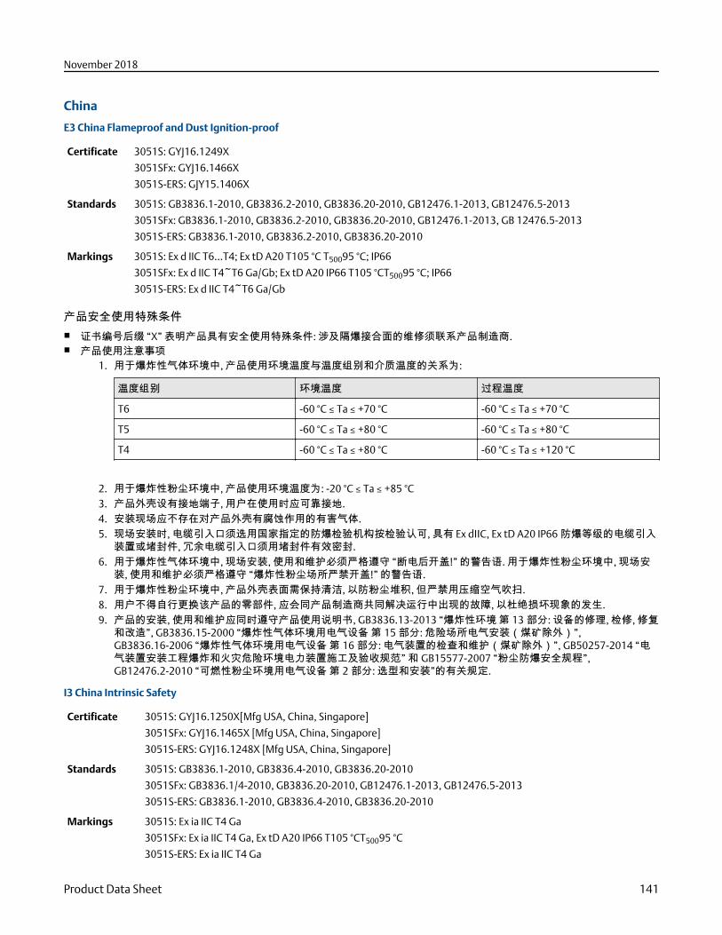
China
E3 China Flameproof and Dust Ignition-proof
Certificate 3051S: GYJ16.1249X
3051SFx: GYJ16.1466X
3051S-ERS: GJY15.1406X
Standards 3051S: GB3836.1-2010, GB3836.2-2010, GB3836.20-2010, GB12476.1-2013, GB12476.5-2013
3051SFx: GB3836.1-2010, GB3836.2-2010, GB3836.20-2010, GB12476.1-2013, GB 12476.5-2013
3051S-ERS: GB3836.1-2010, GB3836.2-2010, GB3836.20-2010
Markings 3051S: Ex d IIC T6…T4; Ex tD A20 T105 °C T50095 °C; IP66
3051SFx: Ex d IIC T4~T6 Ga/Gb; Ex tD A20 IP66 T105 °CT50095 °C; IP66
3051S-ERS: Ex d IIC T4~T6 Ga/Gb
产品安全使用特殊条件■ 证书编号后缀 “X” 表明产品具有安全使用特殊条件: 涉及隔爆接合面的维修须联系产品制造商.■ 产品使用注意事项
1. 用于爆炸性气体环境中, 产品使用环境温度与温度组别和介质温度的关系为:
温度组别 环境温度 过程温度
T6 -60 °C ≤ Ta ≤ +70 °C -60 °C ≤ Ta ≤ +70 °C
T5 -60 °C ≤ Ta ≤ +80 °C -60 °C ≤ Ta ≤ +80 °C
T4 -60 °C ≤ Ta ≤ +80 °C -60 °C ≤ Ta ≤ +120 °C
2. 用于爆炸性粉尘环境中, 产品使用环境温度为: -20 °C ≤ Ta ≤ +85 °C3. 产品外壳设有接地端子, 用户在使用时应可靠接地.4. 安装现场应不存在对产品外壳有腐蚀作用的有害气体.5. 现场安装时, 电缆引入口须选用国家指定的防爆检验机构按检验认可, 具有 Ex dⅡC, Ex tD A20 IP66 防爆等级的电缆引入
装置或堵封件, 冗余电缆引入口须用堵封件有效密封.6. 用于爆炸性气体环境中, 现场安装, 使用和维护必须严格遵守 “断电后开盖!” 的警告语. 用于爆炸性粉尘环境中, 现场安
装, 使用和维护必须严格遵守 “爆炸性粉尘场所严禁开盖!” 的警告语.7. 用于爆炸性粉尘环境中, 产品外壳表面需保持清洁, 以防粉尘堆积, 但严禁用压缩空气吹扫.8. 用户不得自行更换该产品的零部件, 应会同产品制造商共同解决运行中出现的故障, 以杜绝损坏现象的发生.9. 产品的安装, 使用和维护应同时遵守产品使用说明书, GB3836.13-2013 “爆炸性环境 第 13 部分: 设备的修理, 检修, 修复
和改造”, GB3836.15-2000 “爆炸性气体环境用电气设备 第 15 部分: 危险场所电气安装(煤矿除外)”,GB3836.16-2006 “爆炸性气体环境用电气设备 第 16 部分: 电气装置的检查和维护(煤矿除外)”, GB50257-2014 “电气装置安装工程爆炸和火灾危险环境电力装置施工及验收规范” 和 GB15577-2007 “粉尘防爆安全规程”,GB12476.2-2010 “可燃性粉尘环境用电气设备 第 2 部分: 选型和安装”的有关规定.
I3 China Intrinsic Safety
Certificate 3051S: GYJ16.1250X[Mfg USA, China, Singapore]
3051SFx: GYJ16.1465X [Mfg USA, China, Singapore]
3051S-ERS: GYJ16.1248X [Mfg USA, China, Singapore]
Standards 3051S: GB3836.1-2010, GB3836.4-2010, GB3836.20-2010
3051SFx: GB3836.1/4-2010, GB3836.20-2010, GB12476.1-2013, GB12476.5-2013
3051S-ERS: GB3836.1-2010, GB3836.4-2010, GB3836.20-2010
Markings 3051S: Ex ia IIC T4 Ga
3051SFx: Ex ia IIC T4 Ga, Ex tD A20 IP66 T105 °CT50095 °C
3051S-ERS: Ex ia IIC T4 Ga
November 2018
Product Data Sheet 141
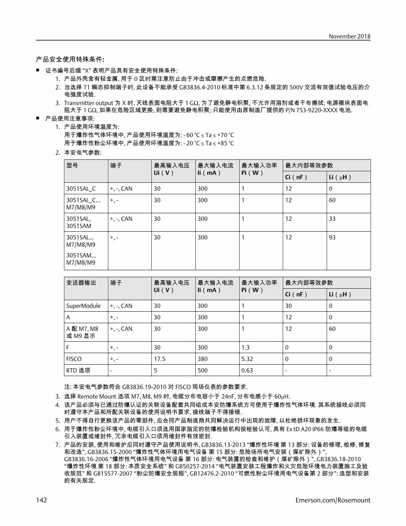
产品安全使用特殊条件:■ 证书编号后缀 “X” 表明产品具有安全使用特殊条件:
1. 产品外壳含有轻金属, 用于 0 区时需注意防止由于冲击或摩擦产生的点燃危险.2. 当选择 T1 瞬态抑制端子时, 此设备不能承受 GB3836.4-2010 标准中第 6.3.12 条规定的 500V 交流有效值试验电压的介
电强度试验.3. Transmitter output 为 X 时, 天线表面电阻大于 1 GΩ, 为了避免静电积聚, 不允许用溶剂或者干布擦拭; 电源模块表面电
阻大于 1 GΩ, 如果在危险区域更换, 则需要避免静电积聚; 只能使用由原制造厂提供的 P/N 753-9220-XXXX 电池.■ 产品使用注意事项:
1. 产品使用环境温度为:用于爆炸性气体环境中, 产品使用环境温度为: - 60 °C ≤ Ta ≤ +70 °C用于爆炸性粉尘环境中, 产品使用环境温度为: - 20 °C ≤ Ta ≤ +85 °C
2. 本安电气参数:
型号 端子 最高输入电压Ui(V)
最大输入电流Ii(mA)
最大输入功率Pi(W)
最大内部等效参数
Ci(nF) Li(μH)
3051SAL_C +, -, CAN 30 300 1 12 0
3051SAL_C…M7/M8/M9
+, - 30 300 1 12 60
3051SAL,3051SAM
+, -, CAN 30 300 1 12 33
3051SAL…M7/M8/M9
3051SAM…M7/M8/M9
+, - 30 300 1 12 93
变送器输出 端子 最高输入电压Ui(V)
最大输入电流Ii(mA)
最大输入功率Pi(W)
最大内部等效参数
Ci(nF) Li(μH)
SuperModule +, -, CAN 30 300 1 30 0
A +, - 30 300 1 12 0
A 配 M7, M8或 M9 显示
+, -, CAN 30 300 1 12 60
F +, - 30 300 1.3 0 0
FISCO +, - 17.5 380 5.32 0 0
RTD 选项 - 5 500 0.63 - -
注: 本安电气参数符合 GB3836.19-2010 对 FISCO 现场仪表的参数要求.
3. 选择 Remote Mount 选项 M7, M8, M9 时, 电缆分布电容小于 24nF, 分布电感小于 60µH.4. 该产品必须与已通过防爆认证的关联设备配套共同组成本安防爆系统方可使用于爆炸性气体环境. 其系统接线必须同
时遵守本产品和所配关联设备的使用说明书要求, 接线端子不得接错.5. 用户不得自行更换该产品的零部件, 应会同产品制造商共同解决运行中出现的故障, 以杜绝损坏现象的发生.6. 用于爆炸性粉尘环境中, 电缆引入口须选用国家指定的防爆检验机构按检验认可, 具有 Ex tD A20 IP66 防爆等级的电缆
引入装置或堵封件, 冗余电缆引入口须用堵封件有效密封.7. 产品的安装, 使用和维护应同时遵守产品使用说明书, GB3836.13-2013 “爆炸性环境 第 13 部分: 设备的修理, 检修, 修复
和改造”, GB3836.15-2000 “爆炸性气体环境用电气设备 第 15 部分: 危险场所电气安装(煤矿除外)”,GB3836.16-2006 “爆炸性气体环境用电气设备 第 16 部分: 电气装置的检查和维护(煤矿除外)”, GB3836.18-2010“爆炸性环境 第 18 部分: 本质安全系统” 和 GB50257-2014 “电气装置安装工程爆炸和火灾危险环境电力装置施工及验收规范” 和 GB15577-2007 “粉尘防爆安全规程”, GB12476.2-2010 “可燃性粉尘环境用电气设备第 2 部分”: 选型和安装的有关规定.
November 2018
142 Emerson.com/Rosemount
N3 China Type n
Certificate 3051S, 3051SHP: GYJ17.1354X
3051SFX: GYJ17.1355X
Markings Ex nA IIC T5 Gc
产品安全使用特殊条件■ 产品防爆合格证号后缀 “X” 代表产品安全使用有特殊条件: 产品选用瞬态保护端子板(c 中包含 T1 选项)时, 设备不能承受
500V 对地电压试验 1 分钟, 安装时需考虑在内.■ 产品使用注意事项
1. 产品使用环境温度范围为: - 40 °C ≤ Ta ≤ +85 °C2. 最高输入电压: 45V3. 现场安装时, 电缆引入口须选用经国家指定的防爆检验机构检验认可的, 具有 Ex eⅡC Gb 或 Ex nA ⅡC Gc 防爆等级的电缆
引入装置或堵封件, 冗余电缆引入口须用堵封件有效密封.4. 安装现场确认无可燃性气体存在时方可维修.5. 用户不得自行更换该产品的零部件, 应会同产品制造商共同解决运行中出现的故障, 以杜绝损坏现象的发生.6. 产品的安装, 使用和维护应同时遵守产品使用说明书, GB3836.13-2013 “爆炸性环境 第 13 部分: 设备的修理, 检修, 修复
和改造”, GB3836.15-2000 “爆炸性气体环境用电气设备 第 15 部分: 危险场所电气安装(煤矿除外)”,GB3836.16-2006 “爆炸性气体环境用电气设备 第 16 部分: 电气装置的检查和维护(煤矿除外)” , GB50257-2014 “电气装置安装工程爆炸和火灾危险环境电力装置施工及验收规范” 的有关规定.
EAC - Belarus, Kazakhstan, Russia
EM Technical Regulation Customs Union (EAC) Flameproof and Dust Ignition-proof
Certificate RU C-US.AA87.B.00378
Markings Ga/Gb Ex d IIC T6…T4 X
Ex tb IIIC T105 °C T50095 °C Db X
Ex ta IIIC T105 °C T50095 °C Da X
IM Technical Regulation Customs Union (EAC) Intrinsic Safety
Certificate RU C-US.AA87.B.00378
Markings 0Ex ia IIC T4 Ga X
IN Technical Regulation Customs Union (EAC) Intrinsic Safety
Certificate: RU C-US.AA87.B.00378
Markings: 0Ex ia IIC T4 Ga X
Japan
E4 Japan Flameproof
Certificate CML 17JPN1147X
3051ERS: TC20215, TC20216, TC20217, TC20218, TC20219, TC20220, TC20221
Markings Ex d IIC T6…T4 Ga/Gb
Temperature class Ambient temperature Process temperature
T6 -40 °C to +70 °C -60 °C to +70 °C
T5 -40 °C to +75 °C -60 °C to +80 °C
November 2018
Product Data Sheet 143
Temperature class Ambient temperature Process temperature
T4 -40 °C to +75 °C -60 °C to +120 °C
Special Conditions for Safe Use:
1. This device contains a thin wall diaphragm less than 1mm thickness that forms a boundary between EPL Ga (processconnection) and EPL Gb (all other parts of the equipment). The model code and datasheet are to be consulted for details ofthe diaphragm material. Installation, maintenance, and use shall consider the environmental conditions to which thediaphragm will be subjected. The manufacturer’s instructions fr installation and maintenance shall be followed in detail toassure safety during its expected lifetime.
2. Flameproof joints are not intended for repair.3. Non-standard paint options may cause risk from electrostatic discharge. Avoid installations that could cause electrostatic
build-up on painted surfaces, and only clean the painted surfaces with a damp cloth. If paint is ordered through a specialoption code, contact the manufacturer for more information.
Republic of Korea
EP Republic of Korea Flameproof
Certificate 12-KB4BO-0180X [Mfg USA], 11-KB4BO-0068X [Mfg Singapore]
Markings Ex d IIC T6...T4
IP Republic of Korea Intrinsic Safety
Certificate 12-KB4BO-0202X [HART - Mfg USA],12-KB4BO-0204X [Fieldbus - Mfg USA], 12-KB4BO-0203X [HART - MfgSingapore], 13-KB4BO-0296X [Fieldbus - Mfg Singapore]
Markings Ex ia IIC T4
Combinations
K1 Combination of E1, I1, N1, and ND
K2 Combination of E2 and I2
K5 Combination of E5 and I5
K6 Combination of E6 and I6
K7 Combination of E7, I7, and N7
KA Combination of E1, I1, E6, and I6
KB Combination of E5, I5, E6, and I6
KC Combination of E1, I1, E5, and I5
KD Combination of E1, I1, E5, I5, E6, and I6
KG Combination of IA, IE, IF, and IG
KM Combination of EM and IM
KP Combination of EP and IP
Additional Certifications
SBS American Bureau of Shipping (ABS) Type Approval
Certificate 17-RJ1679518-PDA
November 2018
144 Emerson.com/Rosemount
Intended Use Measure gauge or absolute pressure of liquid, gas or vapor applications on ABS classed vessels, marine, andoffshore installations.
SBV Bureau Veritas (BV) Type Approval
Certificate 31910 BV
Requirements Bureau Veritas Rules for the Classification of Steel Ships
Application Class Notations: AUT-UMS, AUT-CCS, AUT-PORT and AUT-IMS.
SDN Det Norske Veritas (DNV) Type Approval
Certificate TAA00000K9
Intended Use Det Norske Veritas' Rules for Classification of Ships, High Speed & Light Craft, and Det Norske Veritas' OffshoreStandards
Application
Location classes
Type 3051S
Temperature D
Humidity B
Vibration A
EMC A
Enclosure D/IP66/IP68
SLL Lloyds Register (LR) Type Approval
Certificate 11/60002
Application Environmental categories ENV1, ENV2, ENV3, and ENV5
D3 Custody Transfer - Measurement Canada Accuracy Approval [3051S Only]
Certificate AG-0501, AV-2380C
Rosemount 3051S and 3051SMV WirelessRev 2.4
European directive information
A copy of the EC Declaration of Conformity can be found at the end of the Quick Start Guide. The most recent revision of the ECDeclaration of Conformity can be found at Emerson.com/Rosemount.
Telecommunication Compliance
All wireless devices require certification to ensure that they adhere to regulations regarding the use of the RF spectrum. Nearlyevery country requires this type of product certification.
Emerson is working with governmental agencies around the world to supply fully compliant products and remove the risk ofviolating country directives or laws governing wireless device usage.
November 2018
Product Data Sheet 145
FCC and IC
This device complies with Part 15 of the FCC Rules. Operation is subject to the following conditions: This device may not causeharmful interference. This device must accept any interference received, including interference that may cause undesiredoperation. This device must be installed to ensure a minimum antenna separation distance of 20 cm from all persons.
Ordinary location certification
As standard, the transmitter has been examined and tested to determine that the design meets the basic electrical, mechanical,and fire protection requirements by a nationally recognized test laboratory (NRTL) as accredited by the Federal Occupational Safetyand Health Administration (OSHA).
Installing Equipment in North America
The US National Electrical Code (NEC) and the Canadian Electrical Code (CEC) permit the use of Division marked equipment inZones and Zone marked equipment in Divisions. The markings must be suitable for the area classification, gas, and temperatureclass. This information is clearly defined in the respective codes.
USA
I5 USA Intrinsically Safe (IS), Nonincendive (NI), and Dust-Ignitionproof (DIP)
Certificate FM18US0009X
Standards FM Class 3600 – 2011, FM Class 3610 – 2010, FM Class 3611 – 2004, FM Class 3810 – 2005, NEMA® 250 – 2003
Markings IS CL I, DIV 1, GP A, B, C, D; CL II, DIV 1, GP E, F, G; CL III T4; CL 1, Zone 0 AEx ia IIC T4; NI CL 1, DIV 2, GP A, B, C, D T4;DIP CL II, DIV 1, GP E, F, G; CL III, T5; T4(–50 °C ≤ Ta ≤ +70 °C)/ T5(–50 °C ≤ Ta ≤ +85 °C); when connected perRosemount drawing 03151-1000; Type 4X
Special Conditions for Safe Use (X):
1. The Rosemount 3051S and SMV Wireless Transmitters shall only be used with the 701PBKKF Rosemount SmartPowerBattery Pack (P/N 00753-9220-0001), Computational Systems Inc Battery Pack (P/N MHM-89004) or alternatively thePerpetuum Intelligent Power Module Vibration Harvester (P/N IPM71008).
2. The transmitter may contain more than 10% aluminum and is considered a potential risk of ignition by impact or friction.Care must be taken into account during installation and use to prevent impact and friction.
3. The surface resistivity of the antenna is greater than 1GΩ. To avoid electrostatic charge build-up, it must not be rubbed orcleaned with solvents or a dry cloth.
Canada
I6 Canada Intrinsically Safe
Certificate CSA 1143113
Standards CAN/CSA C22.2 No. 0-10, CSA Std C22.2 No. 30-M1986, CAN/CSA C22.2 No. 94-M91, CSA Std C22.2 No. 142-M1987, CSA Std C22.2 No. 157-92, ANSI/ISA 12.27.01-2003, CSA Std C22.2 No. 60529:05
Markings Intrinsically Safe Class I, Division 1; suitable for Class 1, Zone 0, IIC, T3C; when connected per Rosemount drawing03151-1010; Type 4X
Europe
I1 ATEX Intrinsic Safety
Certificate Baseefa13ATEX0127X
Standards EN 60079-0: 2012, EN 60079-11: 2012
Markings II 1 G Ex ia IIC T4 Ga, T4(–60 °C ≤ Ta ≤ +70 °C)
November 2018
146 Emerson.com/Rosemount
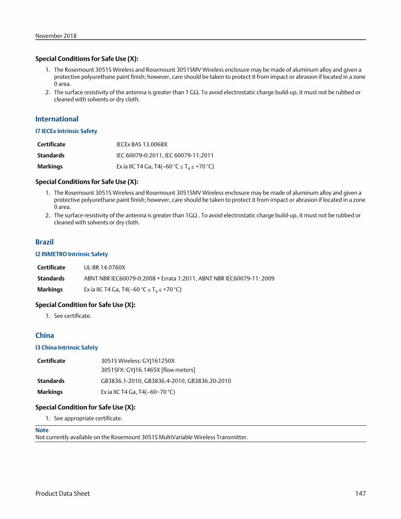
Special Conditions for Safe Use (X):
1. The Rosemount 3051S Wireless and Rosemount 3051SMV Wireless enclosure may be made of aluminum alloy and given aprotective polyurethane paint finish; however, care should be taken to protect it from impact or abrasion if located in a zone0 area.
2. The surface resistivity of the antenna is greater than 1 GΩ. To avoid electrostatic charge build-up, it must not be rubbed orcleaned with solvents or dry cloth.
International
I7 IECEx Intrinsic Safety
Certificate IECEx BAS 13.0068X
Standards IEC 60079-0:2011, IEC 60079-11:2011
Markings Ex ia IIC T4 Ga, T4(–60 °C ≤ Ta ≤ +70 °C)
Special Conditions for Safe Use (X):
1. The Rosemount 3051S Wireless and Rosemount 3051SMV Wireless enclosure may be made of aluminum alloy and given aprotective polyurethane paint finish; however, care should be taken to protect it from impact or abrasion if located in a zone0 area.
2. The surface resistivity of the antenna is greater than 1GΩ . To avoid electrostatic charge build-up, it must not be rubbed orcleaned with solvents or dry cloth.
Brazil
I2 INMETRO Intrinsic Safety
Certificate UL-BR 14.0760X
Standards ABNT NBR IEC60079-0:2008 + Errata 1:2011, ABNT NBR IEC60079-11: 2009
Markings Ex ia IIC T4 Ga, T4(–60 °C ≤ Ta ≤ +70 °C)
Special Condition for Safe Use (X):
1. See certificate.
China
I3 China Intrinsic Safety
Certificate 3051S Wireless: GYJ161250X
3051SFX: GYJ16.1465X [flow meters]
Standards GB3836.1-2010, GB3836.4-2010, GB3836.20-2010
Markings Ex ia IIC T4 Ga, T4(–60~70 °C)
Special Condition for Safe Use (X):
1. See appropriate certificate.
NoteNot currently available on the Rosemount 3051S MultiVariable Wireless Transmitter.
November 2018
Product Data Sheet 147
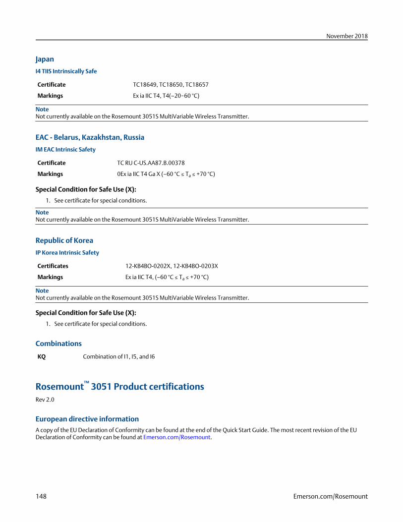
Japan
I4 TIIS Intrinsically Safe
Certificate TC18649, TC18650, TC18657
Markings Ex ia IIC T4, T4(–20~60 °C)
NoteNot currently available on the Rosemount 3051S MultiVariable Wireless Transmitter.
EAC - Belarus, Kazakhstan, Russia
IM EAC Intrinsic Safety
Certificate TC RU C-US.AA87.B.00378
Markings 0Ex ia IIC T4 Ga X (–60 °C ≤ Ta ≤ +70 °C)
Special Condition for Safe Use (X):
1. See certificate for special conditions.
NoteNot currently available on the Rosemount 3051S MultiVariable Wireless Transmitter.
Republic of Korea
IP Korea Intrinsic Safety
Certificates 12-KB4BO-0202X, 12-KB4BO-0203X
Markings Ex ia IIC T4, (–60 °C ≤ Ta ≤ +70 °C)
NoteNot currently available on the Rosemount 3051S MultiVariable Wireless Transmitter.
Special Condition for Safe Use (X):
1. See certificate for special conditions.
Combinations
KQ Combination of I1, I5, and I6
Rosemount™ 3051 Product certificationsRev 2.0
European directive informationA copy of the EU Declaration of Conformity can be found at the end of the Quick Start Guide. The most recent revision of the EUDeclaration of Conformity can be found at Emerson.com/Rosemount.
November 2018
148 Emerson.com/Rosemount
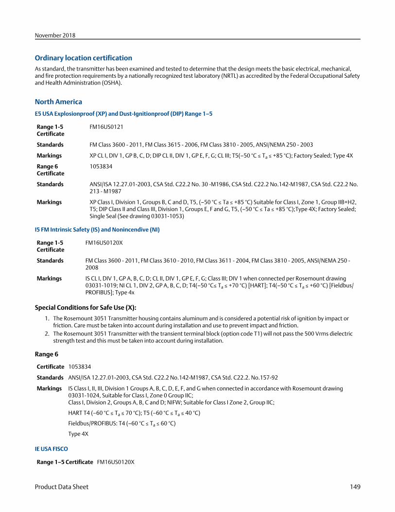
Ordinary location certificationAs standard, the transmitter has been examined and tested to determine that the design meets the basic electrical, mechanical,and fire protection requirements by a nationally recognized test laboratory (NRTL) as accredited by the Federal Occupational Safetyand Health Administration (OSHA).
North America
E5 USA Explosionproof (XP) and Dust-Ignitionproof (DIP) Range 1–5
Range 1-5Certificate
FM16US0121
Standards FM Class 3600 - 2011, FM Class 3615 - 2006, FM Class 3810 - 2005, ANSI/NEMA 250 - 2003
Markings XP CL I, DIV 1, GP B, C, D; DIP CL II, DIV 1, GP E, F, G; CL III; T5(–50 °C ≤ Ta ≤ +85 °C); Factory Sealed; Type 4X
Range 6Certificate
1053834
Standards ANSI/ISA 12.27.01-2003, CSA Std. C22.2 No. 30 -M1986, CSA Std. C22.2 No.142-M1987, CSA Std. C22.2 No.213 - M1987
Markings XP Class I, Division 1, Groups B, C and D, T5, (–50 °C ≤ Ta ≤ +85 °C) Suitable for Class I, Zone 1, Group IIB+H2,T5; DIP Class II and Class III, Division 1, Groups E, F and G, T5, (–50 °C ≤ Ta ≤ +85 °C);Type 4X; Factory Sealed;Single Seal (See drawing 03031-1053)
I5 FM Intrinsic Safety (IS) and Nonincendive (NI)
Range 1-5Certificate
FM16US0120X
Standards FM Class 3600 - 2011, FM Class 3610 - 2010, FM Class 3611 - 2004, FM Class 3810 - 2005, ANSI/NEMA 250 -2008
Markings IS CL I, DIV 1, GP A, B, C, D; CL II, DIV 1, GP E, F, G; Class III; DIV 1 when connected per Rosemount drawing03031-1019; NI CL 1, DIV 2, GP A, B, C, D; T4(–50 °C≤ Ta ≤ +70 °C) [HART]; T4(–50 °C ≤ Ta ≤ +60 °C) [Fieldbus/PROFIBUS]; Type 4x
Special Conditions for Safe Use (X):
1. The Rosemount 3051 Transmitter housing contains aluminum and is considered a potential risk of ignition by impact orfriction. Care must be taken into account during installation and use to prevent impact and friction.
2. The Rosemount 3051 Transmitter with the transient terminal block (option code T1) will not pass the 500 Vrms dielectricstrength test and this must be taken into account during installation.
Range 6
Certificate 1053834
Standards ANSI/ISA 12.27.01-2003, CSA Std. C22.2 No.142-M1987, CSA Std. C22.2. No.157-92
Markings IS Class I, II, III, Division 1 Groups A, B, C, D, E, F, and G when connected in accordance with Rosemount drawing03031-1024, Suitable for Class I, Zone 0 Group IIC;Class I, Division 2, Groups A, B, C and D; NIFW; Suitable for Class I Zone 2, Group IIC;
HART T4 (–60 °C ≤ Ta ≤ 70 °C); T5 (–60 °C ≤ Ta ≤ 40 °C)
Fieldbus/PROFIBUS: T4 (–60 °C ≤ Ta ≤ 60 °C)
Type 4X
IE USA FISCO
Range 1–5 Certificate FM16US0120X
November 2018
Product Data Sheet 149
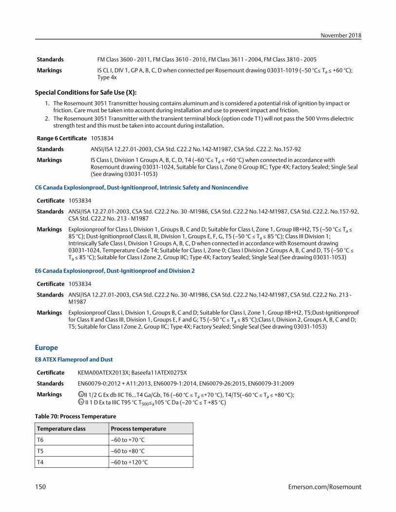
Standards FM Class 3600 - 2011, FM Class 3610 - 2010, FM Class 3611 - 2004, FM Class 3810 - 2005
Markings IS CL I, DIV 1, GP A, B, C, D when connected per Rosemount drawing 03031-1019 (–50 °C≤ Ta ≤ +60 °C);Type 4x
Special Conditions for Safe Use (X):
1. The Rosemount 3051 Transmitter housing contains aluminum and is considered a potential risk of ignition by impact orfriction. Care must be taken into account during installation and use to prevent impact and friction.
2. The Rosemount 3051 Transmitter with the transient terminal block (option code T1) will not pass the 500 Vrms dielectricstrength test and this must be taken into account during installation.
Range 6 Certificate 1053834
Standards ANSI/ISA 12.27.01-2003, CSA Std. C22.2 No.142-M1987, CSA Std. C22.2. No.157-92
Markings IS Class I, Division 1 Groups A, B, C, D, T4 (–60 °C≤ Ta ≤ +60 °C) when connected in accordance withRosemount drawing 03031-1024, Suitable for Class I, Zone 0 Group IIC; Type 4X; Factory Sealed; Single Seal(See drawing 03031-1053)
C6 Canada Explosionproof, Dust-Ignitionproof, Intrinsic Safety and Nonincendive
Certificate 1053834
Standards ANSI/ISA 12.27.01-2003, CSA Std. C22.2 No. 30 -M1986, CSA Std. C22.2 No.142-M1987, CSA Std. C22.2. No.157-92,CSA Std. C22.2 No. 213 - M1987
Markings Explosionproof for Class I, Division 1, Groups B, C and D; Suitable for Class I, Zone 1, Group IIB+H2, T5 (–50 °C≤ Ta ≤85 °C); Dust-Ignitionproof Class II, III, Division 1, Groups E, F, G, T5 (–50 °C ≤ Ta ≤ 85 °C); Class III Division 1;Intrinsically Safe Class I, Division 1 Groups A, B, C, D when connected in accordance with Rosemount drawing03031-1024, Temperature Code T4; Suitable for Class I, Zone 0; Class I Division 2 Groups A, B, C and D, T5 (–50 °C ≤Ta ≤ 85 °C); Suitable for Class I Zone 2, Group IIC; Type 4X; Factory Sealed; Single Seal (See drawing 03031-1053)
E6 Canada Explosionproof, Dust-Ignitionproof and Division 2
Certificate 1053834
Standards ANSI/ISA 12.27.01-2003, CSA Std. C22.2 No. 30 -M1986, CSA Std. C22.2 No.142-M1987, CSA Std. C22.2 No. 213 -M1987
Markings Explosionproof Class I, Division 1, Groups B, C and D; Suitable for Class I, Zone 1, Group IIB+H2, T5;Dust-Ignitionprooffor Class II and Class III, Division 1, Groups E, F and G; T5 (–50 °C ≤ Ta ≤ 85 °C);Class I, Division 2, Groups A, B, C and D;T5; Suitable for Class I Zone 2, Group IIC; Type 4X; Factory Sealed; Single Seal (See drawing 03031-1053)
Europe
E8 ATEX Flameproof and Dust
Certificate KEMA00ATEX2013X; Baseefa11ATEX0275X
Standards EN60079-0:2012 + A11:2013, EN60079-1:2014, EN60079-26:2015, EN60079-31:2009
Markings II 1/2 G Ex db IIC T6...T4 Ga/Gb, T6 (–60 °C ≤ Ta ≤+70 °C), T4/T5(–60 °C ≤ Ta ≤ +80 °C); II 1 D Ex ta IIIC T95 °C T500≤a105 °C Da (–20 °C ≤ T +85 °C)
Table 70: Process Temperature
Temperature class Process temperature
T6 –60 to +70 °C
T5 –60 to +80 °C
T4 –60 to +120 °C
November 2018
150 Emerson.com/Rosemount
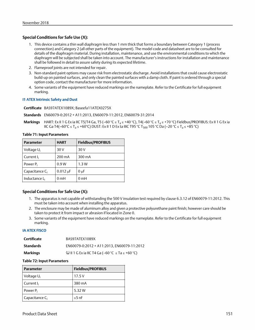
Special Conditions for Safe Use (X):
1. This device contains a thin wall diaphragm less than 1 mm thick that forms a boundary between Category 1 (processconnection) and Category 2 (all other parts of the equipment). The model code and datasheet are to be consulted fordetails of the diaphragm material. During installation, maintenance, and use the environmental conditions to which thediaphragm will be subjected shall be taken into account. The manufacturer’s instructions for installation and maintenanceshall be followed in detail to assure safety during its expected lifetime.
2. Flameproof joints are not intended for repair.3. Non-standard paint options may cause risk from electrostatic discharge. Avoid installations that could cause electrostatic
build-up on painted surfaces, and only clean the painted surfaces with a damp cloth. If paint is ordered through a specialoption code, contact the manufacturer for more information.
4. Some variants of the equipment have reduced markings on the nameplate. Refer to the Certificate for full equipmentmarking.
I1 ATEX Intrinsic Safety and Dust
Certificate BAS97ATEX1089X; Baseefa11ATEX0275X
Standards EN60079-0:2012 + A11:2013, EN60079-11:2012, EN60079-31:2014
Markings HART: Ex II 1 G Ex ia IIC T5/T4 Ga, T5 (–60 °C ≤ Ta ≤ +40 °C), T4(–60 °C ≤ Ta ≤ +70 °C) Fieldbus/PROFIBUS: Ex II 1 G Ex iaIIC Ga T4(–60°C ≤ Ta ≤ +60°C) DUST: Ex II 1 D Ex ta IIIC T95 °C T500 105 °C Da (–20 °C ≤ Ta ≤ +85 °C)
Table 71: Input Parameters
Parameter HART Fieldbus/PROFIBUS
Voltage Ui 30 V 30 V
Current Ii 200 mA 300 mA
Power Pi 0.9 W 1.3 W
Capacitance Ci 0.012 µF 0 µF
Inductance Li 0 mH 0 mH
Special Conditions for Safe Use (X):
1. The apparatus is not capable of withstanding the 500 V insulation test required by clause 6.3.12 of EN60079-11:2012. Thismust be taken into account when installing the apparatus.
2. The enclosure may be made of aluminum alloy and given a protective polyurethane paint finish; however care should betaken to protect it from impact or abrasion if located in Zone 0.
3. Some variants of the equipment have reduced markings on the nameplate. Refer to the Certificate for full equipmentmarking.
IA ATEX FISCO
Certificate BAS97ATEX1089X
Standards EN60079-0:2012 + A11:2013, EN60079-11:2012
Markings II 1 G Ex ia IIC T4 Ga (–60 °C ≤ Ta ≤ +60 °C)
Table 72: Input Parameters
Parameter Fieldbus/PROFIBUS
Voltage Ui 17.5 V
Current Ii 380 mA
Power Pi 5.32 W
Capacitance Ci ≤5 nF
November 2018
Product Data Sheet 151
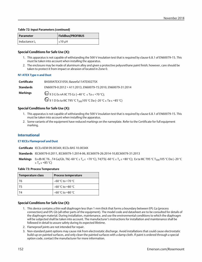
Table 72: Input Parameters (continued)
Parameter Fieldbus/PROFIBUS
Inductance Li ≤10 µH
Special Conditions for Safe Use (X):
1. This apparatus is not capable of withstanding the 500 V insulation test that is required by clause 6.8.1 of EN60079-15. Thismust be taken into account when installing the apparatus.
2. The enclosure may be made of aluminum alloy and given a protective polyurethane paint finish; however, care should betaken to protect it from impact or abrasion of located in Zone 0.
N1 ATEX Type n and Dust
Certificate BAS00ATEX3105X; Baseefa11ATEX0275X
Standards EN60079-0:2012 + A11:2013, EN60079-15:2010, EN60079-31:2014
Markings II 3 G Ex nA IIC T5 Gc (–40 °C ≤ Ta ≤ +70 °C);
II 1 D Ex ta IIIC T95 °C T500105 °C Da (–20 °C ≤ Ta ≤ +85 °C)
Special Conditions for Safe Use (X):
1. This apparatus is not capable of withstanding the 500 V insulation test that is required by clause 6.8.1 of EN60079-15. Thismust be taken into account when installing the apparatus.
2. Some variants of the equipment have reduced markings on the nameplate. Refer to the Certificate for full equipmentmarking.
International
E7 IECEx Flameproof and Dust
Certificate IECEx KEM 09.0034X; IECEx BAS 10.0034X
Standards IEC60079-0:2011, IEC60079-1:2014-06, IEC60079-26:2014-10,IEC60079-31:2013
Markings Ex db IIC T6...T4 Ga/Gb, T6(–60 °C ≤ Ta ≤ +70 °C), T4/T5(–60 °C ≤ Ta ≤ +80 °C); Ex ta IIIC T95 °C T500105 °C Da (–20 °C≤ Ta ≤ +85 °C)
Table 73: Process Temperature
Temperature class Process temperature
T6 –60 °C to +70 °C
T5 –60 °C to +80 °C
T4 –60 °C to +80 °C
Special Conditions for Safe Use (X):
1. This device contains a thin wall diaphragm less than 1 mm thick that forms a boundary between EPL Ga (processconnection) and EPL Gb (all other parts of the equipment). The model code and datasheet are to be consulted for details ofthe diaphragm material. During installation, maintenance, and use the environmental conditions to which the diaphragmwill be subjected shall be taken into account. The manufacturer’s instructions for installation and maintenance shall befollowed in detail to assure safety during its expected lifetime.
2. Flameproof joints are not intended for repair.3. Non-standard paint options may cause risk from electrostatic discharge. Avoid installations that could cause electrostatic
build-up on painted surfaces, and only clean the painted surfaces with a damp cloth. If paint is ordered through a specialoption code, contact the manufacturer for more information.
November 2018
152 Emerson.com/Rosemount
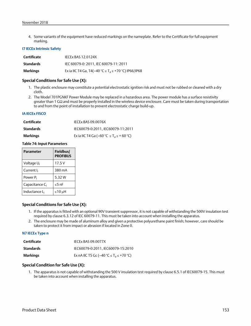
4. Some variants of the equipment have reduced markings on the nameplate. Refer to the Certificate for full equipmentmarking.
I7 IECEx Intrinsic Safety
Certificate IECEx BAS 12.0124X
Standards IEC 60079-0: 2011, IEC 60079-11: 2011
Markings Ex ia IIC T4 Ga, T4(–40 °C ≤ Ta ≤ +70 °C) IP66/IP68
Special Conditions for Safe Use (X):
1. The plastic enclosure may constitute a potential electrostatic ignition risk and must not be rubbed or cleaned with a drycloth.
2. The Model 701PGNKF Power Module may be replaced in a hazardous area. The power module has a surface resistivitygreater than 1 GΩ and must be properly installed in the wireless device enclosure. Care must be taken during transportationto and from the point of installation to prevent electrostatic charge build-up.
IA IECEx FISCO
Certificate IECEx BAS 09.0076X
Standards IEC60079-0:2011, IEC60079-11:2011
Markings Ex ia IIC T4 Ga (–60 °C ≤ Ta ≤ + 60 °C)
Table 74: Input Parameters
Parameter Fieldbus/PROFIBUS
Voltage Ui 17.5 V
Current Ii 380 mA
Power Pi 5.32 W
Capacitance Ci ≤5 nF
Inductance Li ≤10 µH
Special Conditions for Safe Use (X):
1. If the apparatus is fitted with an optional 90V transient suppressor, it is not capable of withstanding the 500V insulation testrequired by clause 6.3.12 of IEC 60079-11. This must be taken into account when installing the apparatus.
2. The enclosure may be made of aluminum alloy and given a protective polyurethane paint finish; however, care should betaken to protect it from impact or abrasion if located in Zone 0.
N7 IECEx Type n
Certificate IECEx BAS 09.0077X
Standards IEC60079-0:2011, IEC60079-15:2010
Markings Ex nA IIC T5 Gc (–40 °C ≤ Ta ≤ +70 °C)
Special Condition for Safe Use (X):
1. The apparatus is not capable of withstanding the 500 V insulation test required by clause 6.5.1 of IEC60079-15. This mustbe taken into account when installing the apparatus.
November 2018
Product Data Sheet 153
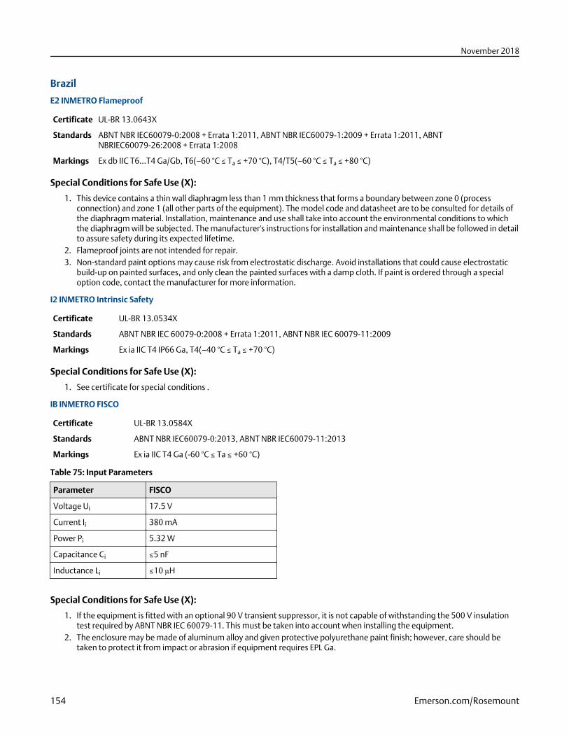
Brazil
E2 INMETRO Flameproof
Certificate UL-BR 13.0643X
Standards ABNT NBR IEC60079-0:2008 + Errata 1:2011, ABNT NBR IEC60079-1:2009 + Errata 1:2011, ABNTNBRIEC60079-26:2008 + Errata 1:2008
Markings Ex db IIC T6…T4 Ga/Gb, T6(–60 °C ≤ Ta ≤ +70 °C), T4/T5(–60 °C ≤ Ta ≤ +80 °C)
Special Conditions for Safe Use (X):
1. This device contains a thin wall diaphragm less than 1 mm thickness that forms a boundary between zone 0 (processconnection) and zone 1 (all other parts of the equipment). The model code and datasheet are to be consulted for details ofthe diaphragm material. Installation, maintenance and use shall take into account the environmental conditions to whichthe diaphragm will be subjected. The manufacturer's instructions for installation and maintenance shall be followed in detailto assure safety during its expected lifetime.
2. Flameproof joints are not intended for repair.3. Non-standard paint options may cause risk from electrostatic discharge. Avoid installations that could cause electrostatic
build-up on painted surfaces, and only clean the painted surfaces with a damp cloth. If paint is ordered through a specialoption code, contact the manufacturer for more information.
I2 INMETRO Intrinsic Safety
Certificate UL-BR 13.0534X
Standards ABNT NBR IEC 60079-0:2008 + Errata 1:2011, ABNT NBR IEC 60079-11:2009
Markings Ex ia IIC T4 IP66 Ga, T4(–40 °C ≤ Ta ≤ +70 °C)
Special Conditions for Safe Use (X):
1. See certificate for special conditions .
IB INMETRO FISCO
Certificate UL-BR 13.0584X
Standards ABNT NBR IEC60079-0:2013, ABNT NBR IEC60079-11:2013
Markings Ex ia IIC T4 Ga (-60 °C ≤ Ta ≤ +60 °C)
Table 75: Input Parameters
Parameter FISCO
Voltage Ui 17.5 V
Current Ii 380 mA
Power Pi 5.32 W
Capacitance Ci ≤5 nF
Inductance Li ≤10 µH
Special Conditions for Safe Use (X):
1. If the equipment is fitted with an optional 90 V transient suppressor, it is not capable of withstanding the 500 V insulationtest required by ABNT NBR IEC 60079-11. This must be taken into account when installing the equipment.
2. The enclosure may be made of aluminum alloy and given protective polyurethane paint finish; however, care should betaken to protect it from impact or abrasion if equipment requires EPL Ga.
November 2018
154 Emerson.com/Rosemount
China
E3 China Flameproof
Certificate GYJ14.1041X; GYJ15.1368X [Flow Meters]
Standards GB12476-2000; GB3836.1-2010, GB3836.2-2010, GB3836.20-2010
Markings 3051 Series: Ex d IIC T6/T5 Ga/Gb, DIP A21 TA90 °C IP66
3051CF Series: Ex d IIC T5/T6 Ga/Gb
产品安全使用特殊条件■ 证书编号后缀 “X” 表明产品具有安全使用特殊条件: 涉及隔爆接合面的维修须联系产品制造商.■ 产品使用注意事项
1. 用于爆炸性气体环境中, 产品使用环境温度之间的关系为:
温度组别 环境温度
T6 - 50 °C ≤ Ta ≤ + 65 °C
T5 - 50 °C ≤ Ta ≤ + 80 °C
2. 产品外壳设有接地端子, 用户在使用时应可靠接地.3. 安装现场应不存在对产品外壳有腐蚀作用的有害气体.4. 现场安装时, 电缆引入口须选用国家指定的防爆检验机构按检验认可, 具有 Ex dⅡC Gb 和 DIP A21 IP66 防爆等级的电缆
引入装置或堵封件, 冗余电缆引入口须用堵封件有效密封.5. 用于爆炸性气体环境中, 现场安装, 使用和维护必须严格遵守“断电后开盖!” 的警告语. 用于爆炸性粉尘环境中, 现场安
装, 使用和维护必须严格遵守 “爆炸性粉尘场所严禁开盖!” 的警告语.6. 用于爆炸性粉尘环境中, 产品外壳表面需保持清洁, 以防粉尘堆积, 但严禁用压缩空气吹扫.7. 用户不得自行更换该产品的零部件, 应会同产品制造商共同解决运行中出现的故障, 以杜绝损坏现象的发生.8. 安装现场确认无可燃性粉尘存在时方可维修.
产品的安装, 使用和维护应同时遵守产品使用说明书, GB3836.13-2013 “爆炸性环境 第 13 部分: 设备的修理, 检修, 修复和改造”, GB3836.15-2000 “爆炸性气体环境用电气设备 第 15 部分: 危险场所电气安装(煤矿除外)”,GB3836.16-2006 “爆炸性气体环境用电气设备 第 16 部分: 电气装置的检查和维护(煤矿除外)”, GB50257-2014 “电气装置安装工程爆炸和火灾危险环境电力装置施工及验收规范”和 GB15577-2007 “粉尘防爆安全规程”,GB12476.2-2010 “可燃性粉尘环境用电气设备 第 1 部分: 用外壳和限制表面温度保护的电气设备 第 2 节 电气设备的选择, 安装和维护”的有关规定.
I3 China Intrinsic Safety
Certificate GYJ13.1362X; GYJ15.1367X [Flow Meters]
Standards GB3836.1-2010, GB3836.4-2010, GB3836.20-2010, GB12476.1-2000
Markings 3051 Series: Ex ia IIC T4/T5 Ga, DIP A20 TA 80 °C IP663051 CF Series: Ex ia IIC T4/T5 Ga
产品安全使用特殊条件:■ 证书编号后缀“X”表明产品具有安全使用特殊条件:
1. 产品(选用铝合金外壳)外壳含有轻金属, 用于 0 区时需注意防止由于冲击或摩擦产生的点燃危险.2. 当选择 T1 瞬态抑制端子时,此设备不能承受 GB3836.4-2010 标准中第 6.3.12 条规定的 500V 交流有效值试验电压的
介电强度试验.3. Transmitter output 为 X 时, 需使用由厂家提供的型号为 701PG 的 Smart Power Green Power Module 电池.4. 产品外壳含有非金属部件, 使用时须防止产生静电火花, 只能用湿布清理.
■ 产品使用注意事项:1. 产品使用环境温度范围:
November 2018
Product Data Sheet 155
气体/粉尘 Transmitter output 温度组别 环境温度范围
气体 A, M T5 -60 °C ~+40 °C
气体 A, M T4 -60 °C ~+70 °C
气体 F, W T4 -60 °C ~+60 °C
气体 X T4 -40 °C ~+70 °C
粉尘 A, F, W T80 °C -20 °C ~+40 °C
2. 本安电气参数:
Transmitteroutput
最高输入电压 Ui(V)
最大输入电流 Ii(mA)
最大输入功率 Pi(W)
最大内部等效参数
Ci(nF) Li(μH)
A, M 30 200 0.9 12 0
F, W 30 300 1.3 0 0
F, W (FISCO) 17.5 380 5.32 5 10
注:Transmitter Output 为 F, W(FISCO)时, 本安电气参数符合 GB3836.19-2010 对 FISCO 现场仪表的参数要求.
3. 该产品必须与已通过防爆认证的关联设备配套共同组成本安防爆系统方可使用于爆炸性气体环境. 其系统接线必须同时遵守本产品和所配关联设备的使用说明书要求, 接线端子不得接错.
4. 该产品与关联设备的连接电缆应为带绝缘护套的屏蔽电缆, 其屏蔽层应在安全场所接地.5. 对于爆炸性粉尘环境, 最大输入电压为:
Transmitter output 最高输入电压
A 55V
F, W 40V
6. 安装现场应不存在对产品外壳有腐蚀作用的有害气体.7. 现场安装时, 电缆引入口须选用国家指定的防爆检验机构按检验认可, 具有 DIP A20 IP66 防爆等级的电缆引入装置, 转
接头或堵封件, 冗余电缆引入口须用堵封件有效密封.8. 对于爆炸性粉尘环境, 现场安装, 使用和维护必须严格遵守 “爆炸性粉尘场所严禁开盖!” 的警告语.9. 用户不得自行更换该产品的零部件, 应会同产品制造商共同解决运行中出现的故障, 以杜绝损坏现象的发生.
10. 安装现场确认无可燃性粉尘存在时方可维修.11. 产品的安装, 使用和维护应同时遵守产品使用说明书, GB3836.13-2013 “爆炸性环境 第 13 部分:设备的修理, 检修, 修
复和改造”, GB3836.15-2000 “爆炸性气体环境用电气设备 第 15 部分:危险场所电气安装(煤矿除外)”,GB3836.16-2006 “爆炸性气体环境用电气设备 第 16 部分:电气装置的检查和维护(煤矿除外)”, GB3836.18-2010“爆炸性环境 第 18 部分:本质安全系统” 和 GB50257-2014 “电气装置安装工程爆炸和火灾危险环境电力装置施工及验收规范”, GB50527-1996 “电气装置安装工程爆炸和火灾危险环境电气装置施工验收规范”以及 GB15577-2007 “粉尘防爆安全规程”, GB12476.2-2006 “可燃性粉尘环境用电气设备 第 1 部分:用外壳和限制表面温度保护的电气设备 第 2节:电气设备的选择, 安装和维护”的有关规定.
N3 China Type n
Certificate GYJ15.1105X
Standards GB3836.1-2010, GB3836.8-2003
Markings Ex nA nL IIC T5 Gc (-40 °C ≤ Ta ≤ +70 °C)
产品安全使用特殊条件■ 产品防爆合格证号后缀 “X” 代表产品安全使用有特殊条件:产品不能承受 GB3836.8-2003 标准第 8.1 条中规定的 500V 对地
电压试验 1 分钟, 安装时需考虑在内.
November 2018
156 Emerson.com/Rosemount
■ 产品使用注意事项1. 产品使用环境温度范围为: -40 °C ≤ Ta ≤ 70 °C2. 最高输入电压:
Transmitter output 最高输入电压
A, M(3051 Enhanced and 3051 Low Power HART)
55V d c
F, W 40V d c
3. 现场安装时, 电缆引入口须选用经国家指定的防爆检验机构检验认可的, 具有 Ex e 或 Ex n 型的电缆引入装置或堵封件,冗余电缆引入口须用堵封件有效密封.
4. 安装现场确认无可燃性气体存在时方可维修.5. 用户不得自行更换该产品的零部件, 应会同产品制造商共同解决运行中出现的故障, 以杜绝损坏现象的发生.6. 产品的安装, 使用和维护应同时遵守产品使用说明书, GB3836.13-2013 “爆炸性环境 第 13 部分:设备的修理, 检修, 修
复和改造”, GB3836.15-2000 “爆炸性气体环境用电气设备 第 15 部分:危险场所电气安装(煤矿除外)”,GB3836.16-2006 “爆炸性气体环境用电气设备 第 16 部分:电气装置的检查和维护(煤矿除外)”, GB50257-1996 “电气装置安装工程爆炸和火灾危险环境电力装置施工及验收规范”的有关规定.
Japan
E4 Japan Flameproof
Certificate TC20577, TC20578, TC20583, TC20584 [HART®]; TC20579, TC20580, TC20581, TC20582 [Fieldbus]
Markings Ex d IIC T5
Republic of Korea
EP Republic of Korea Flameproof
Certificate 11-KB4BO-0188X [Mfg Singapore]
Markings Ex d IIC T6…T4
IP Republic of Korea Intrinsic Safety
Certificate 13-KB4BO-0203X [HART® – Mfg USA], 13-KB4BO-0204X [Fieldbus – Mfg USA], 10-KB4BO-0138X [HART – MfgSingapore], 13-KB4BO-0206X [Fieldbus – Mfg Singapore]
Markings Ex ia IIC T5/T4 (HART); Ex ia IIC T4 (Fieldbus)
Technical Regulations Customs Union (EAC)
EM EAC Flameproof
Markings Ga/Gb Ex d IIC T4... T6 X,T4/T5(–60 °C ≤ Ta ≤ +80 °C),
T6(–60 °C ≤ Ta ≤ +70 °C)
Special Conditions for Safe Use (X):
1. See certificate for special conditions.
November 2018
Product Data Sheet 157
IM EAC Intrinsically Safe
Markings HART: 0Ex ia IIC T4/T5 Ga X, T4(–60 °C ≤ Ta ≤ +70 °C), T5(–60 °C ≤ Ta ≤ +40 °C) Fieldbus/PROFIBUS: 0Ex ia IIC T4 Ga X (–60 °C ≤ Ta ≤ +60 °C)
Special Conditions for Safe Use (X):
1. See certificate for special conditions.
CombinationsK2 Combination of E2 and I2
K5 Combination of E5 and I5
K6 Combination of C6, E8, and I1
K7 Combination of E7, I7, and N7
K8 Combination of E8, I1, and N1
KB Combination of E5, I5, and C6
KD Combination of E8, I1, E5, I5, and C6
KM Combination of EM and IM
KP Combination of EP and IP
Conduit plugs and adapters
Additional certifications
Rosemount 2051 Product CertificationsRev 1.11
European directive information
A copy of the EC Declaration of Conformity can be found at the end of the Quick Start Guide. The most recent revision of the ECDeclaration of Conformity can be found at www.Emerson.com.
Ordinary Location Certification
As standard, the transmitter has been examined and tested to determine that the design meets the basic electrical, mechanical,and fire protection requirements by a nationally recognized test laboratory (NRTL) as accredited by the Federal Occupational Safetyand Health Administration (OSHA).
Hazardous location certifications
NoteDevice ambient temperature ratings and electrical parameters may be limited to the levels dictated by the hazardous locationcertificate parameters.
North America
E5 USA Explosionproof (XP) and Dust-Ignitionproof (DIP)
Certificate FM16US0232
November 2018
158 Emerson.com/Rosemount
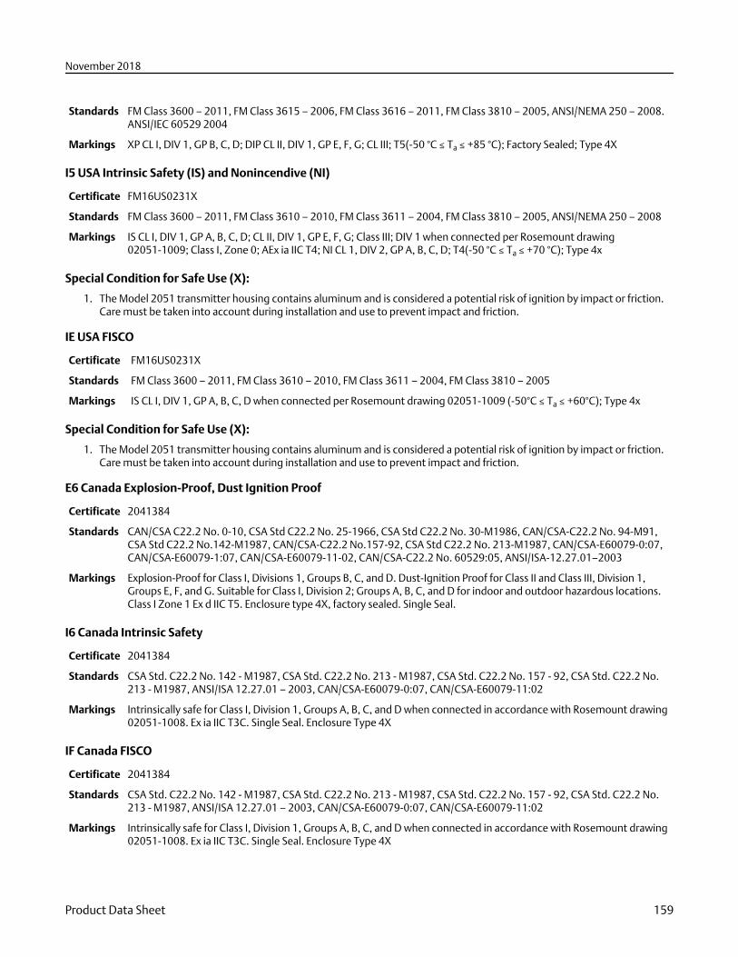
Standards FM Class 3600 – 2011, FM Class 3615 – 2006, FM Class 3616 – 2011, FM Class 3810 – 2005, ANSI/NEMA 250 – 2008.ANSI/IEC 60529 2004
Markings XP CL I, DIV 1, GP B, C, D; DIP CL II, DIV 1, GP E, F, G; CL III; T5(-50 °C ≤ Ta ≤ +85 °C); Factory Sealed; Type 4X
I5 USA Intrinsic Safety (IS) and Nonincendive (NI)
Certificate FM16US0231X
Standards FM Class 3600 – 2011, FM Class 3610 – 2010, FM Class 3611 – 2004, FM Class 3810 – 2005, ANSI/NEMA 250 – 2008
Markings IS CL I, DIV 1, GP A, B, C, D; CL II, DIV 1, GP E, F, G; Class III; DIV 1 when connected per Rosemount drawing02051-1009; Class I, Zone 0; AEx ia IIC T4; NI CL 1, DIV 2, GP A, B, C, D; T4(-50 °C ≤ Ta ≤ +70 °C); Type 4x
Special Condition for Safe Use (X):
1. The Model 2051 transmitter housing contains aluminum and is considered a potential risk of ignition by impact or friction.Care must be taken into account during installation and use to prevent impact and friction.
IE USA FISCO
Certificate FM16US0231X
Standards FM Class 3600 – 2011, FM Class 3610 – 2010, FM Class 3611 – 2004, FM Class 3810 – 2005
Markings IS CL I, DIV 1, GP A, B, C, D when connected per Rosemount drawing 02051-1009 (-50°C ≤ Ta ≤ +60°C); Type 4x
Special Condition for Safe Use (X):
1. The Model 2051 transmitter housing contains aluminum and is considered a potential risk of ignition by impact or friction.Care must be taken into account during installation and use to prevent impact and friction.
E6 Canada Explosion-Proof, Dust Ignition Proof
Certificate 2041384
Standards CAN/CSA C22.2 No. 0-10, CSA Std C22.2 No. 25-1966, CSA Std C22.2 No. 30-M1986, CAN/CSA-C22.2 No. 94-M91,CSA Std C22.2 No.142-M1987, CAN/CSA-C22.2 No.157-92, CSA Std C22.2 No. 213-M1987, CAN/CSA-E60079-0:07,CAN/CSA-E60079-1:07, CAN/CSA-E60079-11-02, CAN/CSA-C22.2 No. 60529:05, ANSI/ISA-12.27.01–2003
Markings Explosion-Proof for Class I, Divisions 1, Groups B, C, and D. Dust-Ignition Proof for Class II and Class III, Division 1,Groups E, F, and G. Suitable for Class I, Division 2; Groups A, B, C, and D for indoor and outdoor hazardous locations.Class I Zone 1 Ex d IIC T5. Enclosure type 4X, factory sealed. Single Seal.
I6 Canada Intrinsic Safety
Certificate 2041384
Standards CSA Std. C22.2 No. 142 - M1987, CSA Std. C22.2 No. 213 - M1987, CSA Std. C22.2 No. 157 - 92, CSA Std. C22.2 No.213 - M1987, ANSI/ISA 12.27.01 – 2003, CAN/CSA-E60079-0:07, CAN/CSA-E60079-11:02
Markings Intrinsically safe for Class I, Division 1, Groups A, B, C, and D when connected in accordance with Rosemount drawing02051-1008. Ex ia IIC T3C. Single Seal. Enclosure Type 4X
IF Canada FISCO
Certificate 2041384
Standards CSA Std. C22.2 No. 142 - M1987, CSA Std. C22.2 No. 213 - M1987, CSA Std. C22.2 No. 157 - 92, CSA Std. C22.2 No.213 - M1987, ANSI/ISA 12.27.01 – 2003, CAN/CSA-E60079-0:07, CAN/CSA-E60079-11:02
Markings Intrinsically safe for Class I, Division 1, Groups A, B, C, and D when connected in accordance with Rosemount drawing02051-1008. Ex ia IIC T3C. Single Seal. Enclosure Type 4X
November 2018
Product Data Sheet 159
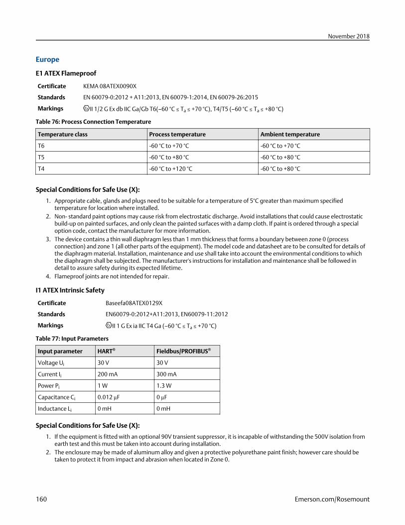
Europe
E1 ATEX Flameproof
Certificate KEMA 08ATEX0090X
Standards EN 60079-0:2012 + A11:2013, EN 60079-1:2014, EN 60079-26:2015
Markings II 1/2 G Ex db IIC Ga/Gb T6(–60 °C ≤ Ta ≤ +70 °C), T4/T5 (–60 °C ≤ Ta ≤ +80 °C)
Table 76: Process Connection Temperature
Temperature class Process temperature Ambient temperature
T6 -60 °C to +70 °C -60 °C to +70 °C
T5 -60 °C to +80 °C -60 °C to +80 °C
T4 -60 °C to +120 °C -60 °C to +80 °C
Special Conditions for Safe Use (X):
1. Appropriate cable, glands and plugs need to be suitable for a temperature of 5°C greater than maximum specifiedtemperature for location where installed.
2. Non- standard paint options may cause risk from electrostatic discharge. Avoid installations that could cause electrostaticbuild-up on painted surfaces, and only clean the painted surfaces with a damp cloth. If paint is ordered through a specialoption code, contact the manufacturer for more information.
3. The device contains a thin wall diaphragm less than 1 mm thickness that forms a boundary between zone 0 (processconnection) and zone 1 (all other parts of the equipment). The model code and datasheet are to be consulted for details ofthe diaphragm material. Installation, maintenance and use shall take into account the environmental conditions to whichthe diaphragm shall be subjected. The manufacturer's instructions for installation and maintenance shall be followed indetail to assure safety during its expected lifetime.
4. Flameproof joints are not intended for repair.
I1 ATEX Intrinsic Safety
Certificate Baseefa08ATEX0129X
Standards EN60079-0:2012+A11:2013, EN60079-11:2012
Markings II 1 G Ex ia IIC T4 Ga (–60 °C ≤ Ta ≤ +70 °C)
Table 77: Input Parameters
Input parameter HART® Fieldbus/PROFIBUS®
Voltage Ui 30 V 30 V
Current Ii 200 mA 300 mA
Power Pi 1 W 1.3 W
Capacitance Ci 0.012 µF 0 µF
Inductance Li 0 mH 0 mH
Special Conditions for Safe Use (X):
1. If the equipment is fitted with an optional 90V transient suppressor, it is incapable of withstanding the 500V isolation fromearth test and this must be taken into account during installation.
2. The enclosure may be made of aluminum alloy and given a protective polyurethane paint finish; however care should betaken to protect it from impact and abrasion when located in Zone 0.
November 2018
160 Emerson.com/Rosemount
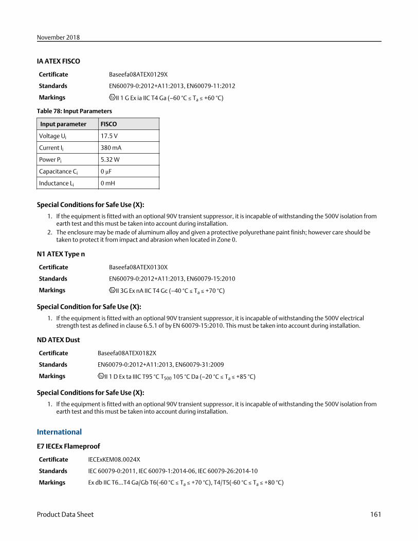
IA ATEX FISCO
Certificate Baseefa08ATEX0129X
Standards EN60079-0:2012+A11:2013, EN60079-11:2012
Markings II 1 G Ex ia IIC T4 Ga (–60 °C ≤ Ta ≤ +60 °C)
Table 78: Input Parameters
Input parameter FISCO
Voltage Ui 17.5 V
Current Ii 380 mA
Power Pi 5.32 W
Capacitance Ci 0 µF
Inductance Li 0 mH
Special Conditions for Safe Use (X):
1. If the equipment is fitted with an optional 90V transient suppressor, it is incapable of withstanding the 500V isolation fromearth test and this must be taken into account during installation.
2. The enclosure may be made of aluminum alloy and given a protective polyurethane paint finish; however care should betaken to protect it from impact and abrasion when located in Zone 0.
N1 ATEX Type n
Certificate Baseefa08ATEX0130X
Standards EN60079-0:2012+A11:2013, EN60079-15:2010
Markings II 3G Ex nA IIC T4 Gc (–40 °C ≤ Ta ≤ +70 °C)
Special Condition for Safe Use (X):
1. If the equipment is fitted with an optional 90V transient suppressor, it is incapable of withstanding the 500V electricalstrength test as defined in clause 6.5.1 of by EN 60079-15:2010. This must be taken into account during installation.
ND ATEX Dust
Certificate Baseefa08ATEX0182X
Standards EN60079-0:2012+A11:2013, EN60079-31:2009
Markings II 1 D Ex ta IIIC T95 °C T500 105 °C Da (–20 °C ≤ Ta ≤ +85 °C)
Special Conditions for Safe Use (X):
1. If the equipment is fitted with an optional 90V transient suppressor, it is incapable of withstanding the 500V isolation fromearth test and this must be taken into account during installation.
International
E7 IECEx Flameproof
Certificate IECExKEM08.0024X
Standards IEC 60079-0:2011, IEC 60079-1:2014-06, IEC 60079-26:2014-10
Markings Ex db IIC T6...T4 Ga/Gb T6(-60 °C ≤ Ta ≤ +70 °C), T4/T5(-60 °C ≤ Ta ≤ +80 °C)
November 2018
Product Data Sheet 161
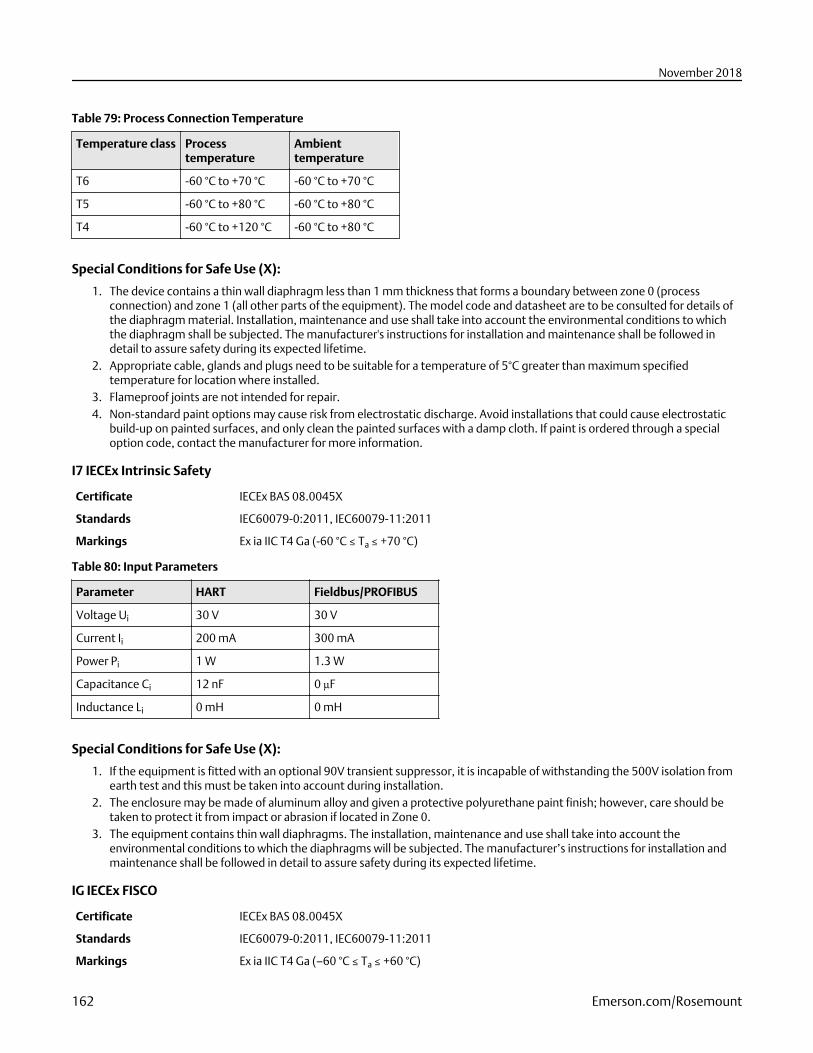
Table 79: Process Connection Temperature
Temperature class Processtemperature
Ambienttemperature
T6 -60 °C to +70 °C -60 °C to +70 °C
T5 -60 °C to +80 °C -60 °C to +80 °C
T4 -60 °C to +120 °C -60 °C to +80 °C
Special Conditions for Safe Use (X):
1. The device contains a thin wall diaphragm less than 1 mm thickness that forms a boundary between zone 0 (processconnection) and zone 1 (all other parts of the equipment). The model code and datasheet are to be consulted for details ofthe diaphragm material. Installation, maintenance and use shall take into account the environmental conditions to whichthe diaphragm shall be subjected. The manufacturer's instructions for installation and maintenance shall be followed indetail to assure safety during its expected lifetime.
2. Appropriate cable, glands and plugs need to be suitable for a temperature of 5°C greater than maximum specifiedtemperature for location where installed.
3. Flameproof joints are not intended for repair.4. Non-standard paint options may cause risk from electrostatic discharge. Avoid installations that could cause electrostatic
build-up on painted surfaces, and only clean the painted surfaces with a damp cloth. If paint is ordered through a specialoption code, contact the manufacturer for more information.
I7 IECEx Intrinsic Safety
Certificate IECEx BAS 08.0045X
Standards IEC60079-0:2011, IEC60079-11:2011
Markings Ex ia IIC T4 Ga (-60 °C ≤ Ta ≤ +70 °C)
Table 80: Input Parameters
Parameter HART Fieldbus/PROFIBUS
Voltage Ui 30 V 30 V
Current Ii 200 mA 300 mA
Power Pi 1 W 1.3 W
Capacitance Ci 12 nF 0 µF
Inductance Li 0 mH 0 mH
Special Conditions for Safe Use (X):
1. If the equipment is fitted with an optional 90V transient suppressor, it is incapable of withstanding the 500V isolation fromearth test and this must be taken into account during installation.
2. The enclosure may be made of aluminum alloy and given a protective polyurethane paint finish; however, care should betaken to protect it from impact or abrasion if located in Zone 0.
3. The equipment contains thin wall diaphragms. The installation, maintenance and use shall take into account theenvironmental conditions to which the diaphragms will be subjected. The manufacturer’s instructions for installation andmaintenance shall be followed in detail to assure safety during its expected lifetime.
IG IECEx FISCO
Certificate IECEx BAS 08.0045X
Standards IEC60079-0:2011, IEC60079-11:2011
Markings Ex ia IIC T4 Ga (–60 °C ≤ Ta ≤ +60 °C)
November 2018
162 Emerson.com/Rosemount
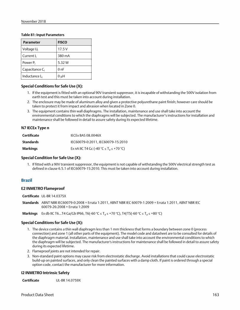
Table 81: Input Parameters
Parameter FISCO
Voltage Ui 17.5 V
Current Ii 380 mA
Power Pi 5.32 W
Capacitance Ci 0 nF
Inductance Li 0 µH
Special Conditions for Safe Use (X):
1. If the equipment is fitted with an optional 90V transient suppressor, it is incapable of withstanding the 500V isolation fromearth test and this must be taken into account during installation.
2. The enclosure may be made of aluminum alloy and given a protective polyurethane paint finish; however care should betaken to protect it from impact and abrasion when located in Zone 0.
3. The equipment contains thin wall diaphragms. The installation, maintenance and use shall take into account theenvironmental conditions to which the diaphragms will be subjected. The manufacturer’s instructions for installation andmaintenance shall be followed in detail to assure safety during its expected lifetime.
N7 IECEx Type n
Certificate IECEx BAS 08.0046X
Standards IEC60079-0:2011, IEC60079-15:2010
Markings Ex nA IIC T4 Gc (-40 °C ≤ Ta ≤ +70 °C)
Special Condition for Safe Use (X):
1. If fitted with a 90V transient suppressor, the equipment is not capable of withstanding the 500V electrical strength test asdefined in clause 6.5.1 of IEC60079-15:2010. This must be taken into account during installation.
Brazil
E2 INMETRO Flameproof
Certificate UL-BR 14.0375X
Standards ABNT NBR IEC60079-0:2008 + Errata 1:2011, ABNT NBR IEC 60079-1:2009 + Errata 1:2011, ABNT NBR IEC60079-26:2008 + Errata 1:2009
Markings Ex db IIC T6...T4 Ga/Gb IP66, T6(-60 °C ≤ Ta ≤ +70 °C), T4/T5(-60 °C ≤ Ta ≤ +80 °C)
Special Conditions for Safe Use (X):
1. The device contains a thin wall diaphragm less than 1 mm thickness that forms a boundary between zone 0 (processconnection) and zone 1 (all other parts of the equipment). The model code and datasheet are to be consulted for details ofthe diaphragm material. Installation, maintenance and use shall take into account the environmental conditions to whichthe diaphragm will be subjected. The manufacturer's instructions for maintenance shall be followed in detail to assure safetyduring its expected lifetime.
2. Flameproof joints are not intended for repair.3. Non-standard paint options may cause risk from electrostatic discharge. Avoid installations that could cause electrostatic
build-up on painted surfaces, and only clean the painted surfaces with a damp cloth. If paint is ordered through a specialoption code, contact the manufacturer for more information.
I2 INMETRO Intrinsic Safety
Certificate UL-BR 14.0759X
November 2018
Product Data Sheet 163
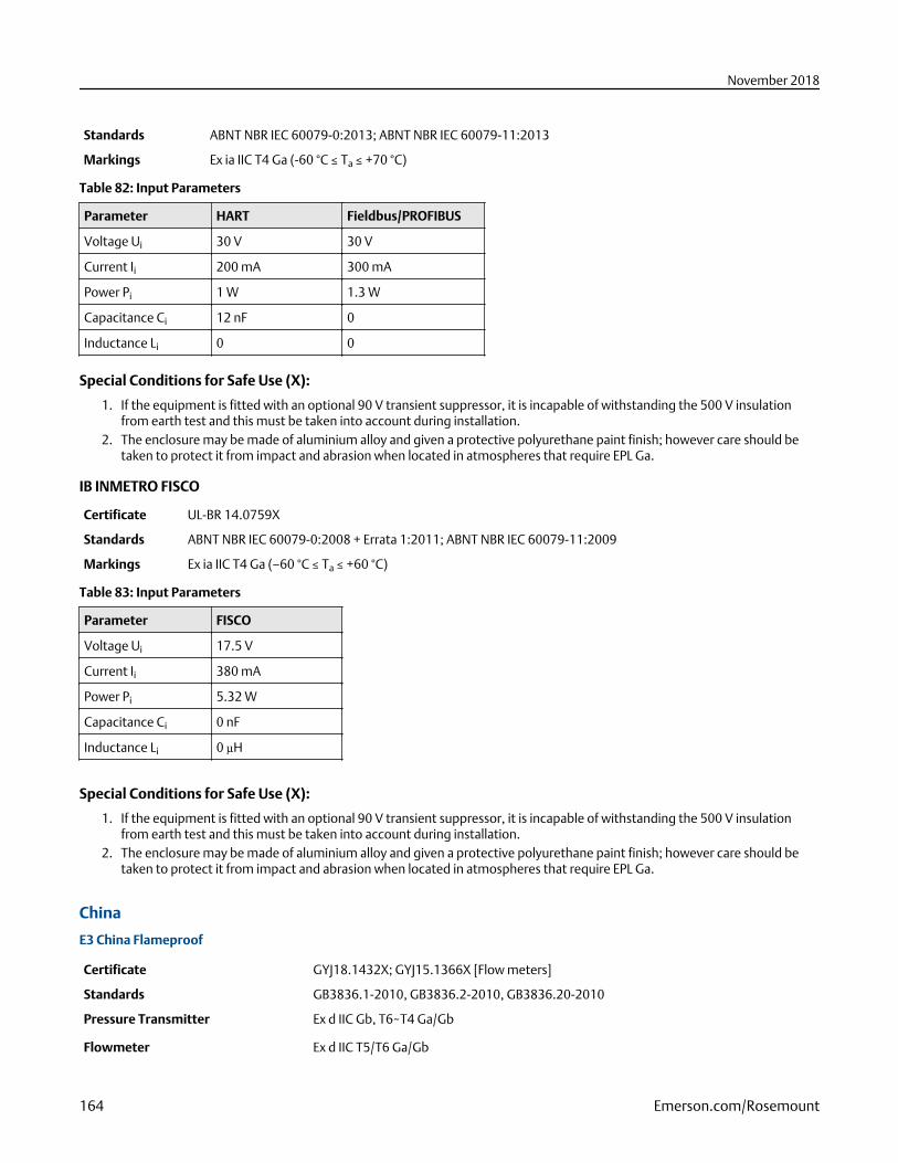
Standards ABNT NBR IEC 60079-0:2013; ABNT NBR IEC 60079-11:2013
Markings Ex ia IIC T4 Ga (-60 °C ≤ Ta ≤ +70 °C)
Table 82: Input Parameters
Parameter HART Fieldbus/PROFIBUS
Voltage Ui 30 V 30 V
Current Ii 200 mA 300 mA
Power Pi 1 W 1.3 W
Capacitance Ci 12 nF 0
Inductance Li 0 0
Special Conditions for Safe Use (X):
1. If the equipment is fitted with an optional 90 V transient suppressor, it is incapable of withstanding the 500 V insulationfrom earth test and this must be taken into account during installation.
2. The enclosure may be made of aluminium alloy and given a protective polyurethane paint finish; however care should betaken to protect it from impact and abrasion when located in atmospheres that require EPL Ga.
IB INMETRO FISCO
Certificate UL-BR 14.0759X
Standards ABNT NBR IEC 60079-0:2008 + Errata 1:2011; ABNT NBR IEC 60079-11:2009
Markings Ex ia IIC T4 Ga (–60 °C ≤ Ta ≤ +60 °C)
Table 83: Input Parameters
Parameter FISCO
Voltage Ui 17.5 V
Current Ii 380 mA
Power Pi 5.32 W
Capacitance Ci 0 nF
Inductance Li 0 µH
Special Conditions for Safe Use (X):
1. If the equipment is fitted with an optional 90 V transient suppressor, it is incapable of withstanding the 500 V insulationfrom earth test and this must be taken into account during installation.
2. The enclosure may be made of aluminium alloy and given a protective polyurethane paint finish; however care should betaken to protect it from impact and abrasion when located in atmospheres that require EPL Ga.
China
E3 China Flameproof
Certificate GYJ18.1432X; GYJ15.1366X [Flow meters]
Standards GB3836.1-2010, GB3836.2-2010, GB3836.20-2010
Pressure Transmitter Ex d IIC Gb, T6~T4 Ga/Gb
Flowmeter Ex d IIC T5/T6 Ga/Gb
November 2018
164 Emerson.com/Rosemount
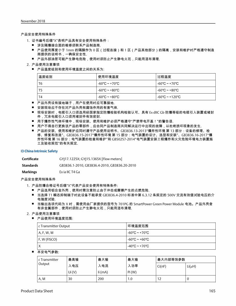
产品安全使用特殊条件
1. 证书编号后缀“X”表明产品具有安全使用特殊条件:■ 涉及隔爆接合面的维修须联系产品制造商.■ 产品使用厚度小于 1mm 的隔膜作为 0 区(过程连接)和 1 区(产品其他部分)的隔离,安装和维护时严格遵守制造
商提供的说明书,一确保安全性.■ 产品外部涂层可能产生静电危险,使用时须防止产生静电火花,只能用湿布清理.
2. 产品使用注意事项■ 产品温度组别和使用环境温度之间的关系为:
温度组别 使用环境温度 过程温度
T6 -60℃~+70℃ -60℃~+70℃
T5 -60℃~+80℃ -60℃~+80℃
T4 -60℃~+80℃ -60℃~+120℃■ 产品外壳设有接地端子,用户在使用时应可靠接地.■ 安装现场应不存在对产品外壳有腐蚀作用的有害气体.■ 现场安装时,电缆引入口须选用经国家指定防爆检验机构检验认可、具有 Ex dⅡC Gb 防爆等级的电缆引入装置或堵封
件,冗余电缆引入口须用堵封件有效密封.■ 用于爆炸性气体环境中,现场安装、使用和维护必须严格遵守“严禁带电开盖!”的警告语.■ 用户不得自行更换该产品的零部件,应会同产品制造商共同解决运行中出现的故障,以杜绝损坏现象的发生.■ 产品的安装、使用和维护应同时遵守产品使用说明书、GB3836.13-2013“爆炸性环境 第 13 部分:设备的修理、检
修、修复和改造”、GB3836.15-2017“爆炸性环境 第 15 部分:电气装置的设计、选型和安装”、GB3836.16-2017“爆炸性环境 第 16 部分:电气装置的检查和维护”和 GB50257-2014“电气装置安装工程爆炸和火灾危险环境电力装置施工及验收规范”的有关规定.
I3 China Intrinsic Safety
Certificate GYJ17.1225X; GYJ15.1365X [Flow meters]
Standards GB3836.1-2010, GB3836.4-2010, GB3836.20-2010
Markings Ex ia IIC T4 Ga
产品安全使用特殊条件
1. 产品防爆合格证号后缀“X”代表产品安全使用有特殊条件:■ 产品选用铝合金外壳,使用时需注意防止由于冲击或摩擦产生的点燃危险.■ 当选择 T1 瞬态抑制端子时此设备不能承受 GB3836.4-2010 标准中第 6.3.12 条规定的 500V 交流有效值试验电压的介
电强度试验.■ 当输出选项代码为 X 时,需使用由厂家提供的型号为 701PG 的 SmartPower Green Power Module 电池。产品外壳含
有非金属部件,使用时须防止产生静电火花,只能用湿布清理.
2. 产品使用注意事项■ 产品使用环境温度范围:
c Transmitter Output 环境温度范围
A, F, W, M -60℃~+70℃
F, W (FISCO) -60℃~+60℃
X -40℃~+70℃■ 本安电气参数:
c TransmitterOutput
最高输
入电压
Ui (V)
最大输
入电流
Ii (mA)
最大输
入功率
Pi (W)
最大内部等效参数
Ci(nF) Li(µH)
A, M 30 200 1.0 12 0
November 2018
Product Data Sheet 165
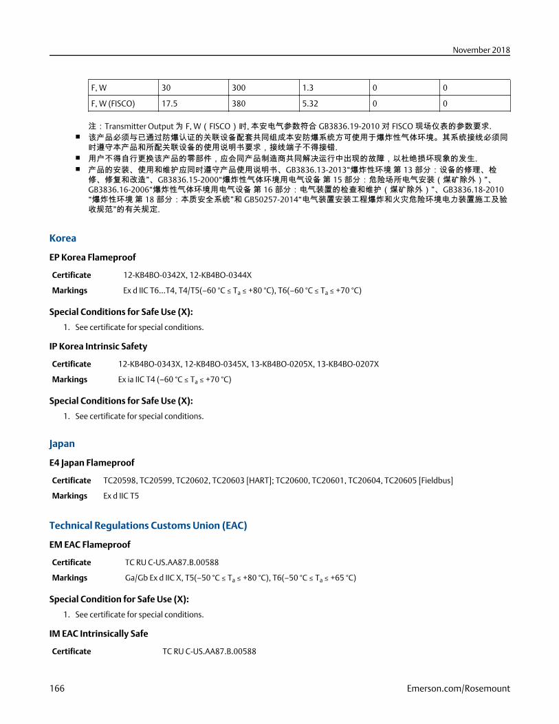
F, W 30 300 1.3 0 0
F, W (FISCO) 17.5 380 5.32 0 0
注:Transmitter Output 为 F, W(FISCO)时, 本安电气参数符合 GB3836.19-2010 对 FISCO 现场仪表的参数要求.■ 该产品必须与已通过防爆认证的关联设备配套共同组成本安防爆系统方可使用于爆炸性气体环境。其系统接线必须同
时遵守本产品和所配关联设备的使用说明书要求,接线端子不得接错.■ 用户不得自行更换该产品的零部件,应会同产品制造商共同解决运行中出现的故障,以杜绝损坏现象的发生.■ 产品的安装、使用和维护应同时遵守产品使用说明书、GB3836.13-2013“爆炸性环境 第 13 部分:设备的修理、检
修、修复和改造”、GB3836.15-2000“爆炸性气体环境用电气设备 第 15 部分:危险场所电气安装(煤矿除外)”、GB3836.16-2006“爆炸性气体环境用电气设备 第 16 部分:电气装置的检查和维护(煤矿除外)”、GB3836.18-2010“爆炸性环境 第 18 部分:本质安全系统”和 GB50257-2014“电气装置安装工程爆炸和火灾危险环境电力装置施工及验收规范”的有关规定.
Korea
EP Korea Flameproof
Certificate 12-KB4BO-0342X, 12-KB4BO-0344X
Markings Ex d IIC T6…T4, T4/T5(–60 °C ≤ Ta ≤ +80 °C), T6(–60 °C ≤ Ta ≤ +70 °C)
Special Conditions for Safe Use (X):
1. See certificate for special conditions.
IP Korea Intrinsic Safety
Certificate 12-KB4BO-0343X, 12-KB4BO-0345X, 13-KB4BO-0205X, 13-KB4BO-0207X
Markings Ex ia IIC T4 (–60 °C ≤ Ta ≤ +70 °C)
Special Conditions for Safe Use (X):
1. See certificate for special conditions.
Japan
E4 Japan Flameproof
Certificate TC20598, TC20599, TC20602, TC20603 [HART]; TC20600, TC20601, TC20604, TC20605 [Fieldbus]
Markings Ex d IIC T5
Technical Regulations Customs Union (EAC)
EM EAC Flameproof
Certificate TC RU C-US.AA87.B.00588
Markings Ga/Gb Ex d IIC X, T5(–50 °C ≤ Ta ≤ +80 °C), T6(–50 °C ≤ Ta ≤ +65 °C)
Special Condition for Safe Use (X):
1. See certificate for special conditions.
IM EAC Intrinsically Safe
Certificate TC RU C-US.AA87.B.00588
November 2018
166 Emerson.com/Rosemount
Markings 0Ex ia IIC T4 Ga X (–60 °C ≤ Ta ≤ +70 °C)
Special Condition for Safe Use (X):
1. See certificate for special conditions.
Combinations
K1 Combination of E1, I1, N1, and ND
K2 Combination of E2 and I2
K5 Combination of E5 and I5
K6 Combination of E6 and I6
K7 Combination of E7, I7, N7 and IECEx Dust
IECEx Dust
Certificate IECEx BAS 08.0058X
Standards IEC60079-0:2011, IEC60079-31:2008
Markings Ex tA IIIC T95 °C T500 105 °C Da (–20 °C ≤ Ta ≤ +85 °C)
Special Condition for Safe Use (X):1. If the equipment is fitted with an optional 90 V transient suppressor, it is incapable of withstanding a
500V isolation from earth test and this must be taken into account during installation.
KA Combination of E1, I1, and K6
KB Combination of K5 and K6
KC Combination of E1, I1, and K5
KD Combination of K1, K5, and K6
KP Combination of EP and IP
KM Combination of EM and IM
Additional Certifications
SBS American Bureau of Shipping (ABS) Type Approval
Certificate 18-HS1753847-PDA
Intended Use Marine & Offshore Applications – Measurement of either Gauge or Absolute Pressure for Liquid, Gas, and Vapor
ABS Rules 2018 Steel Vessels Rules 1-1-4/7.7, 1-1-Appendix 3, 1-1-Appendix 4
SBV Bureau Veritas (BV) Type Approval
Certificate 23157/BV
BV Rules Bureau Veritas Rules for the Classification of Steel Ships
Application Class notations: AUT-UMS, AUT-CCS, AUT-PORT and AUT-IMS; Pressure transmitter type 2051 cannot be installedon diesel engines
SDN Det Norske Veritas (DNV) Type Approval
Certificate TAA000004F
November 2018
Product Data Sheet 167
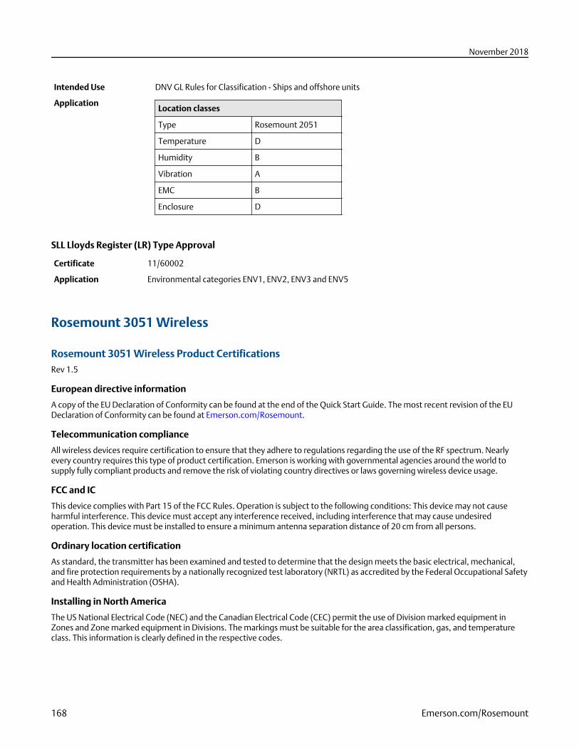
Intended Use DNV GL Rules for Classification - Ships and offshore units
ApplicationLocation classes
Type Rosemount 2051
Temperature D
Humidity B
Vibration A
EMC B
Enclosure D
SLL Lloyds Register (LR) Type Approval
Certificate 11/60002
Application Environmental categories ENV1, ENV2, ENV3 and ENV5
Rosemount 3051 Wireless
Rosemount 3051 Wireless Product CertificationsRev 1.5
European directive information
A copy of the EU Declaration of Conformity can be found at the end of the Quick Start Guide. The most recent revision of the EUDeclaration of Conformity can be found at Emerson.com/Rosemount.
Telecommunication compliance
All wireless devices require certification to ensure that they adhere to regulations regarding the use of the RF spectrum. Nearlyevery country requires this type of product certification. Emerson is working with governmental agencies around the world tosupply fully compliant products and remove the risk of violating country directives or laws governing wireless device usage.
FCC and IC
This device complies with Part 15 of the FCC Rules. Operation is subject to the following conditions: This device may not causeharmful interference. This device must accept any interference received, including interference that may cause undesiredoperation. This device must be installed to ensure a minimum antenna separation distance of 20 cm from all persons.
Ordinary location certification
As standard, the transmitter has been examined and tested to determine that the design meets the basic electrical, mechanical,and fire protection requirements by a nationally recognized test laboratory (NRTL) as accredited by the Federal Occupational Safetyand Health Administration (OSHA).
Installing in North America
The US National Electrical Code (NEC) and the Canadian Electrical Code (CEC) permit the use of Division marked equipment inZones and Zone marked equipment in Divisions. The markings must be suitable for the area classification, gas, and temperatureclass. This information is clearly defined in the respective codes.
November 2018
168 Emerson.com/Rosemount
U.S.A.
I5 U.S.A. Intrinsically Safe (IS)
Ranges 1–5
Certificate FM 3046325
Standards FM Class 3600 - 2011, FM Class 3610 - 2010, FM Class 3810 - 2005, ANSI/ISA 60079-0 - 2009, ANSI/ISA 60079-11 -2009, NEMA 250 - 2003, ANSI/IEC 60529
Markings IS CL I, DIV 1, GP A, B, C, D T4; CL 1, Zone 0 AEx ia IIC T4; T4(–40 °C ≤ Ta ≤ +70 °C) when installed per Rosemountdrawing 03031-1062; Type 4X/IP66/IP68
Special Conditions for Safe Use (X):
1. The Rosemount 3051 Wireless Pressure Transmitter shall only be used with the 701PGNKF Rosemount SmartPower BatteryPack.
2. The inline pressure sensor may contain more than 10% aluminum and is considered a potential risk of ignition by impact orfriction. Care must be taken into account during installation and used to prevent impact and friction.
3. The surface resistivity of the transmitter housing is greater than one gigaohm. To avoid electrostatic charge build-up, itmust not be rubbed or cleaned with solvents or a dry cloth.
Range 6
Certificate CSA 2526009
Standards FM Class 3600 - 2011, FM Class 3610 - 2010, FM Class 3810 - 2005, ANSI/ISA 60079-0 - 2009, ANSI/ISA 60079-11 -2009, UL 61010-1 (3rd edition), UL50E (1st Edition)
Markings IS CL I, DIV 1, GP A, B, C, D T4; CL 1, Zone 0 AEx ia IIC T4; T4(-40 °C ≤ Ta ≤ +70 °C) when installed per Rosemountdrawing 03031-1063; Type 4X/IP66/IP68
Canada
I6 Canada Intrinsically Safe
Certificate CSA 2526009
Standards CAN/CSA C22.2 No. 0-M91, CAN/CSA C22.2 No.94-M91, CSA Std C22.2 No. 142-M1987, CSA Std C22.2 No. 157-92,CSA Std C22.2 No. 60529:05
Markings Intrinsically Safe for Class I, Division 1, Groups A, B, C, D, T4 when installed per Rosemount drawing 03031-1063;Type 4X/IP66/IP68
Europe
I1 ATEX Intrinsic Safety
Certificate Baseefa12ATEX0228X
Standards EN 60079-0: 2012, EN 60079-11: 2012
Markings Ex II 1 G Ex ia IIC T4 Ga, T4(–40 °C ≤ Ta ≤ +70 °C) IP66/IP68
Special Conditions for Safe Use (X):
1. The plastic enclosure may constitute a potential electrostatic ignition risk and must not be rubbed or cleaned with a drycloth.
2. The Model 701PGNKF Power Module may be replaced in a hazardous area. The power module has a surface resistivitygreater than 1 GΩ and must be properly installed in the wireless device enclosure. Care must be taken during transportationto and from the point of installation to prevent electrostatic charge build-up.
November 2018
Product Data Sheet 169
International
I7 IECEx Intrinsic Safety
Certificate IECEx BAS 12.0124X
Standards IEC 60079-0: 2011, IEC 60079-11: 2011
Markings Ex ia IIC T4 Ga, T4(–40 °C ≤ Ta ≤ +70 °C) IP66/IP68
Special Conditions for Safe Use (X):
1. The plastic enclosure may constitute a potential electrostatic ignition risk and must not be rubbed or cleaned with a drycloth.
2. The Model 701PGNKF Power Module may be replaced in a hazardous area. The power module has a surface resistivitygreater than 1 GΩ and must be properly installed in the wireless device enclosure. Care must be taken during transportationto and from the point of installation to prevent electrostatic charge build-up.
Brazil
I2 INMETRO Intrinsic Safety
Certificate UL-BR 13.0534X
Standards ABNT NBR IEC 60079-0:2008 + Errata 1:2011, ABNT NBR IEC 60079-11:2009
Markings Ex ia IIC T4 IP66 Ga, T4(–40 °C ≤ Ta ≤ +70 °C)
Special Conditions for Safe Use (X):
1. See certificate for special conditions .
China
I3 China Intrinsic Safety
Certificate GYJ13.1362X, GYJ15.1367X [Flow meters]
Standards GB3836.1-2010, GB3836.4-2010, GB3836.20-2010
Markings Ex ia IIC T4 Ga, T4(–40~+70 °C)
Special Conditions for Safe Use (X):
1. See certificate for special conditions.
Japan
I4 TIIS Intrinsic Safety
Certificate TC22022X (Rosemount 3051C/L), TC22023X (Rosemount 3051T), TC22024X (Rosemount 3051CFx)
Markings Ex ia IIC T4 Ga, T4(–20 ≤ Ta ≤ +60 °C)
Special Conditions for Safe Use (X):
1. See certificate for special conditions.
November 2018
170 Emerson.com/Rosemount
EAC - Belarus, Kazakhstan, Russia
IM Technical Regulation Customs Union (EAC) Intrinsic Safety
Certificate TU RU C-US.AA87.B.00534
Markings 0Ex ia IIC T4 Ga X; (–40 °C ≤ Ta ≤ +70 °C)
Special Conditions for Safe Use (X):
1. See certificate for special conditions.
Korea
IP Korea Intrinsic Safety
Certificate 13-KB4BO-0295X
Markings Ex ia IIC T4 (–40 °C ≤ Ta ≤ +70 °C)
Special Conditions for Safe Use (X):
1. See certificate for special conditions.
Additional certifications
SBS American Bureau of Shipping (ABS) Type Approval
Certificate 15-HS1405241-PDA
Intended Use Marine & Offshore Applications – Measurement of either gauge or absolute pressure for liquid, gas and vapor.
SBV Bureau Veritas (BV) Type Approval
Certificate 23155
Requirements Bureau Veritas Rules for the Classification of Steel Ships
Application Class notations: AUT-UMS, AUT-CCS, AUT-PORT and AUT-IMS; Pressure transmitter type 3051 cannot be installedon diesel engines.
SDN Det Norske Veritas (DNV) Type Approval
Certificate TAA000004F
Intended Use DNV GL Rules for Classification - Ships and offshore units
ApplicationLocation classes
Temperature D
Humidity B
Vibration A
EMC B
Enclosure D
November 2018
Product Data Sheet 171
Rosemount 2051 Wireless
Rosemount 2051 Wireless Product CertificationsRev 1.4
European directive information
A copy of the EC Declaration of Conformity can be found at the end of the Quick Start Guide. The most recent revision of the ECDeclaration of Conformity can be found at Emerson.com/Rosemount.
Telecommunication compliance
All wireless devices require certification to ensure that they adhere to regulations regarding the use of the RF spectrum. Nearlyevery country requires this type of product certification. Emerson is working with governmental agencies around the world tosupply fully compliant products and remove the risk of violating country directives or laws governing wireless device usage.
FCC and IC
This device complies with Part 15 of the FCC Rules. Operation is subject to the following conditions: This device may not causeharmful interference. This device must accept any interference received, including interference that may cause undesiredoperation. This device must be installed to ensure a minimum antenna separation distance of 20 cm from all persons.
Ordinary location certification
As standard, the transmitter has been examined and tested to determine that the design meets the basic electrical, mechanical,and fire protection requirements by a nationally recognized test laboratory (NRTL) as accredited by the Federal Occupational Safetyand Health Administration (OSHA).
Installing in North America
The US National Electrical Code (NEC) and the Canadian Electrical Code (CEC) permit the use of Division marked equipment inZones and Zone marked equipment in Divisions. The markings must be suitable for the area Classification, gas, and temperatureClass. This information is clearly defined in the respective codes.
U.S.A.
I5 U.S.A. Intrinsically Safe (IS)
Certificate FM 3046325
Standards FM Class 3600 - 2011, FM Class 3610 - 2010, FM Class 3810 - 2005, ANSI/ISA 60079-0 - 2009, ANSI/ISA 60079-11 -2009, NEMA 250 - 2003, ANSI/IEC 60529
Markings IS CL I, DIV 1, GP A, B, C, D T4; CL 1, Zone 0 AEx ia IIC T4; T4(–40 °C ≤ Ta ≤ +70 °C) when installed per Rosemountdrawing 03031-1062; Type 4X/IP66/IP68
Special Conditions for Safe Use (X):
1. The Model 2051 Wireless Pressure Transmitter shall only be used with the 701PGNKF Rosemount SmartPower Battery Pack.2. The inline pressure sensor may contain more than 10% aluminum and is considered a potential risk of ignition by impact or
friction. Care must be taken into account during installation and used to prevent impact and friction.3. The surface resistivity of the transmitter housing is greater than one gigaohm. To avoid electrostatic charge build-up, it
must not be rubbed or cleaned with solvents or a dry cloth.
Canada
I6 Canada Intrinsically Safe
Certificate CSA 2526009
Standards CAN/CSA C22.2 No. 0-M91, CAN/CSA C22.2 No. 94-M91, CSA Std C22.2 No. 142-M1987, CSA Std C22.2 No. 157-92,CSA Std C22.2 No. 60529:05
November 2018
172 Emerson.com/Rosemount
Markings Intrinsically Safe for Class I, Division 1, Groups A, B, C, D, T4 when installed per Rosemount drawing 03031-1063;Type 4X/IP66/IP68
Europe
I1 ATEX Intrinsic Safety
Certificate Baseefa12ATEX0228X
Standards EN 60079-0: 2012, EN 60079-11: 2012
Markings II 1 G Ex ia IIC T4 Ga, T4(–40 °C ≤ Ta ≤ +70 °C) IP66/IP68
Special Conditions for Safe Use (X):
1. The plastic enclosure may constitute a potential electrostatic ignition risk and must not be rubbed or cleaned with a drycloth.
2. The Model 701PGNKF Power Module may be replaced in a hazardous area. The power module has a surface resistivitygreater than 1GΩ and must be properly installed in the wireless device enclosure. Care must be taken during transportationto and from the point of installation to prevent electrostatic charge build-up.
International
I7 IECEx Intrinsic Safety
Certificate IECEx BAS 12.0124X
Standards IEC 60079-0: 2011, IEC 60079-11: 2011
Markings Ex ia IIC T4 Ga, T4(–40 °C ≤ Ta ≤ +70 °C) IP66/IP68
Special Conditions for Safe Use (X):
1. The plastic enclosure may constitute a potential electrostatic ignition risk and must not be rubbed or cleaned with a drycloth.
2. The Model 701PGNKF Power Module may be replaced in a hazardous area. The power module has a surface resistivitygreater than 1GΩ and must be properly installed in the wireless device enclosure. Care must be taken during transportationto and from the point of installation to prevent electrostatic charge build-up.
Brazil
I2 INMETRO Intrinsic Safety
Certificate UL-BR 13.0534X
Standards ABNT NBR IEC 60079-0:2008 + Errata 1:2011, ABNT NBR IEC 60079-11:2009
Markings Ex ia IIC T4 IP66 Ga, T4(–40 °C ≤ Ta ≤ +70 °C)
Special Conditions for Safe Use (X):
1. See certificate for special conditions.
China
I3 China Intrinsic Safety
Certificate GYJ17.1225X
GYJ17.1225X GYJ15.1365X [Flow meters]
Standards GB3836.1-2010, GB3836.4-2010, GB3836.20-2010
Markings Ex ia IIC Ga T4, –40~+70 °C
November 2018
Product Data Sheet 173
Special Conditions for Safe Use (X):
1. See certificate for special conditions.
Japan
I4 TIIS Intrinsic Safety
Certificate TC22022X (2051C/L) TC22023X (2051T)
Standards TC22024X (2051CFx)
Markings Ex ia IIC T4 Ga, T4(-20~+60 °C)
Special Conditions for Safe Use (X):
1. See certificate for special conditions.
EAC - Belarus, Kazakhstan, Russia
IM Technical Regulation Customs Union (EAC) Intrinsic Safety
Certificate RU C-US.ГБ05.B.00390
Markings 0Ex ia IIC T4 Ga X;
Special Conditions for Safe Use (X):
1. See certificate for special conditions.
Korea
IP Korea Intrinsic Safety
Certificate 13-KB4BO-0220X
Markings Ex ia IIC T4 (–40 °C ≤ Ta ≤ +70 °C)
Special Conditions for Safe Use (X):
1. See certificate for special conditions.
Additional certifications
SBS American Bureau of Shipping (ABS) Type Approval
Certificate 15-HS1405241-PDA
Intended Use Marine & Offshore Applications – Measurement of either gauge or absolute pressure for liquid, gas and vapor.
SBV Bureau Veritas (BV) Type Approval
Certificate 23157 BV
Requirements Bureau Veritas Rules for the Classification of Steel Ships
Application Class notations: AUT-UMS, AUT-CCS, AUT-PORT and AUT-IMS; Pressure transmitter type 2051 cannot be installedon diesel engines.
SDN Det Norske Veritas (DNV) Type Approval
Certificate TAA000004F
Intended Use DNV GL Rules for Classification - Ships and offshore units
November 2018
174 Emerson.com/Rosemount
ApplicationLocation classes
Type 2051
Temperature B
Humidity B
Vibration A
EMC B
Enclosure D
Dimensional Drawings
Figure 8: Rosemount 3051S ERS Measurement Transmitter - Coplanar Style
5.17
(131)
6.44
(164)
9.63
(245)
4.20
(107)
Dimensions are in inches (millimeters).
November 2018
Product Data Sheet 175
Figure 9: Rosemount 3051S ERS Measurement Transmitter - In-Line Style
Dimensions are in inches (millimeters).
Figure 10: Rosemount 3051S Scalable Level Transmitter with FF - Coplanar Style
+ Direct mount
extension length
5.17(131)
4.51(114)
8.57(217,7)
4.20(107)
3.62(92)
Lower housing (flushing ring) is available with FFW style flange.
Dimensions are in inches (millimeters).
November 2018
176 Emerson.com/Rosemount
Figure 11: Rosemount 3051S Scalable Level Transmitter with FF - In-Line Style
5.17(131)
8.04(204)
1.50(38)
4.20(107)
Lower housing (flushing ring) is available with FFW style flange.
Dimensions are in inches (millimeters).
Figure 12: Rosemount 3051S Scalable Level Transmitter with Thermal Range Expander – Coplanar Style
5.17(131)
4.20(107)
8.57(217.7)
7.64(194.2)
Dimensions are in inches (millimeters).
November 2018
Product Data Sheet 177
Figure 13: Rosemount 3051S Scalable Level Transmitter with Thermal Range Expander – In-Line Style
4.20(107)
8.04(204)
5.17(131)
13.51(343.2)
1.5(38.1)
Dimensions are in inches (millimeters).
Figure 14: Rosemount 3051S Scalable Level Transmitter with RF - Coplanar Style
5.17(131)
4.55(116)
4.20(107)
8.57(217,7)
3.62(92)
+ Direct mountextension length
Dimensions are in inches (millimeters).
November 2018
178 Emerson.com/Rosemount
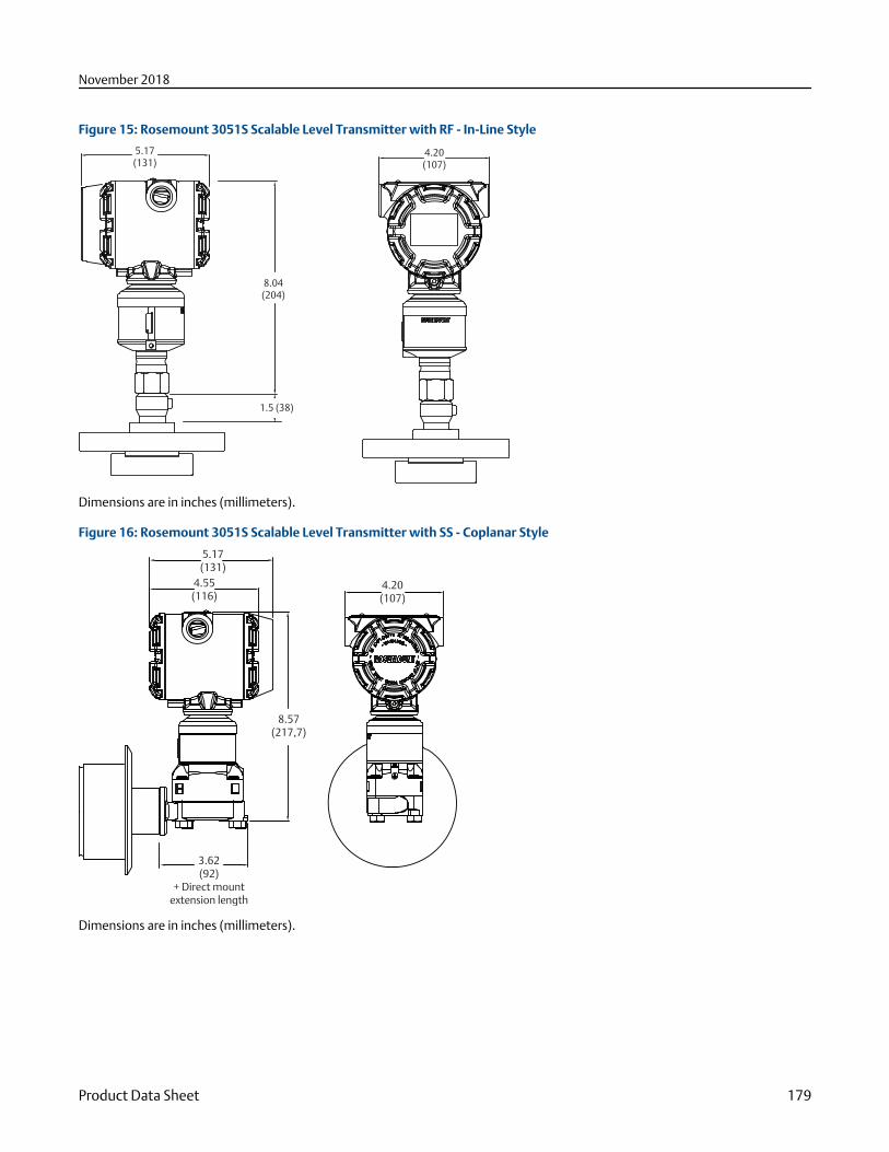
Figure 15: Rosemount 3051S Scalable Level Transmitter with RF - In-Line Style
5.17(131)
4.20(107)
8.04(204)
1.5 (38)
Dimensions are in inches (millimeters).
Figure 16: Rosemount 3051S Scalable Level Transmitter with SS - Coplanar Style
3.62(92)
+ Direct mountextension length
8.57(217,7)
4.55(116)
5.17(131)
4.20(107)
Dimensions are in inches (millimeters).
November 2018
Product Data Sheet 179
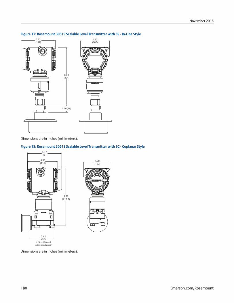
Figure 17: Rosemount 3051S Scalable Level Transmitter with SS - In-Line Style5.17
(131)4.20
(107)
8.04(204)
1.50 (38)
Dimensions are in inches (millimeters).
Figure 18: Rosemount 3051S Scalable Level Transmitter with SC - Coplanar Style
5.17(131)
4.55(116)
4.20(107)
8.57(217,7)
3.62(92)
+ Direct MountExtension Length
Dimensions are in inches (millimeters).
November 2018
180 Emerson.com/Rosemount
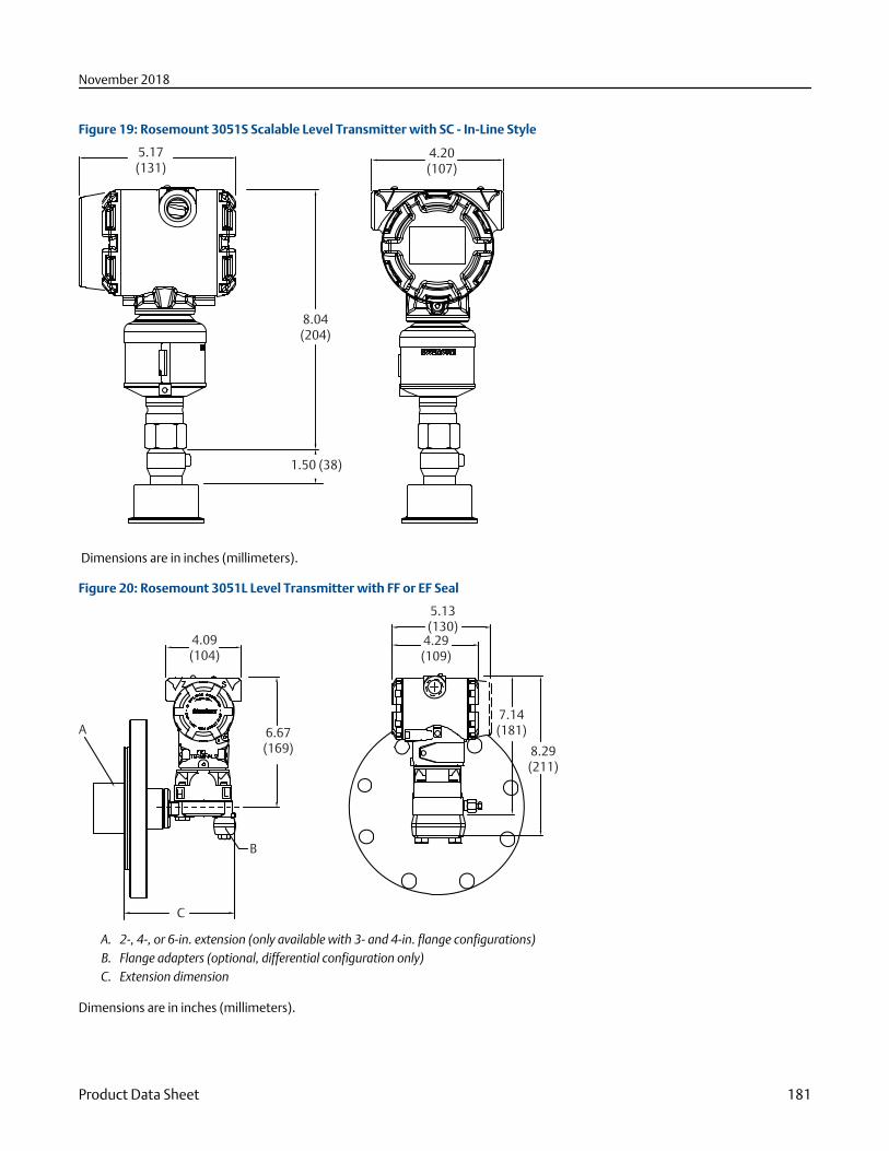
Figure 19: Rosemount 3051S Scalable Level Transmitter with SC - In-Line Style
5.17(131)
4.20(107)
8.04(204)
1.50 (38)
Dimensions are in inches (millimeters).
Figure 20: Rosemount 3051L Level Transmitter with FF or EF Seal
A
B
4.09(104)
6.67(169)
5.13(130)4.29(109)
7.14(181)
8.29(211)
C
A. 2-, 4-, or 6-in. extension (only available with 3- and 4-in. flange configurations)B. Flange adapters (optional, differential configuration only)C. Extension dimension
Dimensions are in inches (millimeters).
November 2018
Product Data Sheet 181
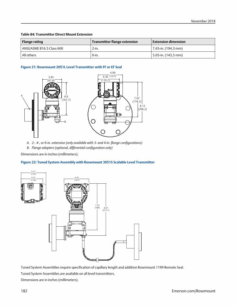
Table 84: Transmitter Direct Mount Extension
Flange rating Transmitter flange extension Extension dimension
ANSI/ASME B16.5 Class 600 2-in. 7.65-in. (194,3 mm)
All others 0-in. 5.65-in. (143,5 mm)
Figure 21: Rosemount 2051L Level Transmitter with FF or EF Seal
A
B
3.85(97.8)
6.6(167,7)
4.99(127)4.36
(110.7)
7.02(178,2)
8.12(206,2)
A. 2-. 4-, or 6-in. extension (only available with 3- and 4-in. flange configurations)B. Flange adapters (optional, differential configuration only)
Dimensions are in inches (millimeters).
Figure 22: Tuned System Assembly with Rosemount 3051S Scalable Level Transmitter
5.31(132)
4.55(116)
4.20 (107)
7.70(196) 8.57
(217,7)
Tuned System Assemblies require specification of capillary length and addition Rosemount 1199 Remote Seal.
Tuned System Assemblies are available on all level transmitters.
Dimensions are in inches (millimeters).
November 2018
182 Emerson.com/Rosemount
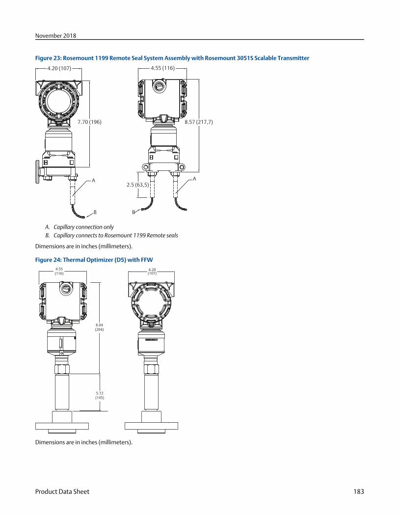
Figure 23: Rosemount 1199 Remote Seal System Assembly with Rosemount 3051S Scalable Transmitter
A A
B B
2.5 (63,5)
8.57 (217,7)
4.55 (116)4.20 (107)
7.70 (196)
A. Capillary connection onlyB. Capillary connects to Rosemount 1199 Remote seals
Dimensions are in inches (millimeters).
Figure 24: Thermal Optimizer (D5) with FFW4.55(116)
8.04(204)
5.72(145)
4.20(107)
Dimensions are in inches (millimeters).
November 2018
Product Data Sheet 183
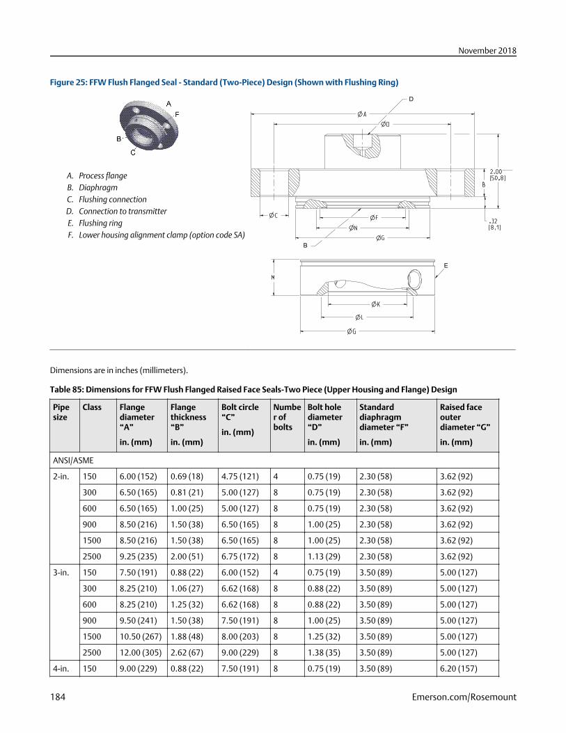
Figure 25: FFW Flush Flanged Seal - Standard (Two-Piece) Design (Shown with Flushing Ring)
A. Process flangeB. DiaphragmC. Flushing connectionD. Connection to transmitterE. Flushing ringF. Lower housing alignment clamp (option code SA)
D
B
E
Dimensions are in inches (millimeters).
Table 85: Dimensions for FFW Flush Flanged Raised Face Seals-Two Piece (Upper Housing and Flange) Design
Pipesize
Class Flangediameter“A”
in. (mm)
Flangethickness“B”
in. (mm)
Bolt circle“C”
in. (mm)
Number ofbolts
Bolt holediameter“D”
in. (mm)
Standarddiaphragmdiameter “F”
in. (mm)
Raised faceouterdiameter “G”
in. (mm)
ANSI/ASME
2-in. 150 6.00 (152) 0.69 (18) 4.75 (121) 4 0.75 (19) 2.30 (58) 3.62 (92)
300 6.50 (165) 0.81 (21) 5.00 (127) 8 0.75 (19) 2.30 (58) 3.62 (92)
600 6.50 (165) 1.00 (25) 5.00 (127) 8 0.75 (19) 2.30 (58) 3.62 (92)
900 8.50 (216) 1.50 (38) 6.50 (165) 8 1.00 (25) 2.30 (58) 3.62 (92)
1500 8.50 (216) 1.50 (38) 6.50 (165) 8 1.00 (25) 2.30 (58) 3.62 (92)
2500 9.25 (235) 2.00 (51) 6.75 (172) 8 1.13 (29) 2.30 (58) 3.62 (92)
3-in. 150 7.50 (191) 0.88 (22) 6.00 (152) 4 0.75 (19) 3.50 (89) 5.00 (127)
300 8.25 (210) 1.06 (27) 6.62 (168) 8 0.88 (22) 3.50 (89) 5.00 (127)
600 8.25 (210) 1.25 (32) 6.62 (168) 8 0.88 (22) 3.50 (89) 5.00 (127)
900 9.50 (241) 1.50 (38) 7.50 (191) 8 1.00 (25) 3.50 (89) 5.00 (127)
1500 10.50 (267) 1.88 (48) 8.00 (203) 8 1.25 (32) 3.50 (89) 5.00 (127)
2500 12.00 (305) 2.62 (67) 9.00 (229) 8 1.38 (35) 3.50 (89) 5.00 (127)
4-in. 150 9.00 (229) 0.88 (22) 7.50 (191) 8 0.75 (19) 3.50 (89) 6.20 (157)
November 2018
184 Emerson.com/Rosemount
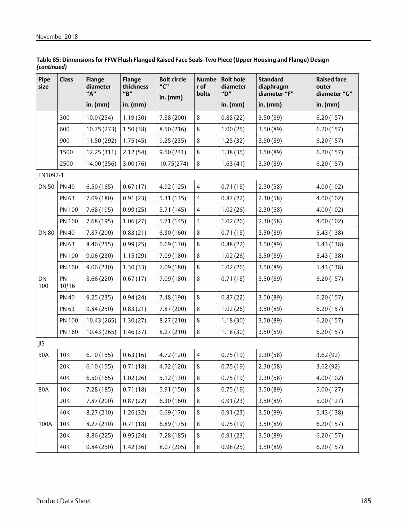
Table 85: Dimensions for FFW Flush Flanged Raised Face Seals-Two Piece (Upper Housing and Flange) Design(continued)
Pipesize
Class Flangediameter“A”
in. (mm)
Flangethickness“B”
in. (mm)
Bolt circle“C”
in. (mm)
Number ofbolts
Bolt holediameter“D”
in. (mm)
Standarddiaphragmdiameter “F”
in. (mm)
Raised faceouterdiameter “G”
in. (mm)
300 10.0 (254) 1.19 (30) 7.88 (200) 8 0.88 (22) 3.50 (89) 6.20 (157)
600 10.75 (273) 1.50 (38) 8.50 (216) 8 1.00 (25) 3.50 (89) 6.20 (157)
900 11.50 (292) 1.75 (45) 9.25 (235) 8 1.25 (32) 3.50 (89) 6.20 (157)
1500 12.25 (311) 2.12 (54) 9.50 (241) 8 1.38 (35) 3.50 (89) 6.20 (157)
2500 14.00 (356) 3.00 (76) 10.75(274) 8 1.63 (41) 3.50 (89) 6.20 (157)
EN1092-1
DN 50 PN 40 6.50 (165) 0.67 (17) 4.92 (125) 4 0.71 (18) 2.30 (58) 4.00 (102)
PN 63 7.09 (180) 0.91 (23) 5.31 (135) 4 0.87 (22) 2.30 (58) 4.00 (102)
PN 100 7.68 (195) 0.99 (25) 5.71 (145) 4 1.02 (26) 2.30 (58) 4.00 (102)
PN 160 7.68 (195) 1.06 (27) 5.71 (145) 4 1.02 (26) 2.30 (58) 4.00 (102)
DN 80 PN 40 7.87 (200) 0.83 (21) 6.30 (160) 8 0.71 (18) 3.50 (89) 5.43 (138)
PN 63 8.46 (215) 0.99 (25) 6.69 (170) 8 0.88 (22) 3.50 (89) 5.43 (138)
PN 100 9.06 (230) 1.15 (29) 7.09 (180) 8 1.02 (26) 3.50 (89) 5.43 (138)
PN 160 9.06 (230) 1.30 (33) 7.09 (180) 8 1.02 (26) 3.50 (89) 5.43 (138)
DN100
PN10/16
8.66 (220) 0.67 (17) 7.09 (180) 8 0.71 (18) 3.50 (89) 6.20 (157)
PN 40 9.25 (235) 0.94 (24) 7.48 (190) 8 0.87 (22) 3.50 (89) 6.20 (157)
PN 63 9.84 (250) 0.83 (21) 7.87 (200) 8 1.02 (26) 3.50 (89) 6.20 (157)
PN 100 10.43 (265) 1.30 (27) 8.27 (210) 8 1.18 (30) 3.50 (89) 6.20 (157)
PN 160 10.43 (265) 1.46 (37) 8.27 (210) 8 1.18 (30) 3.50 (89) 6.20 (157)
JIS
50A 10K 6.10 (155) 0.63 (16) 4.72 (120) 4 0.75 (19) 2.30 (58) 3.62 (92)
20K 6.10 (155) 0.71 (18) 4.72 (120) 8 0.75 (19) 2.30 (58) 3.62 (92)
40K 6.50 (165) 1.02 (26) 5.12 (130) 8 0.75 (19) 2.30 (58) 4.00 (102)
80A 10K 7.28 (185) 0.71 (18) 5.91 (150) 8 0.75 (19) 3.50 (89) 5.00 (127)
20K 7.87 (200) 0.87 (22) 6.30 (160) 8 0.91 (23) 3.50 (89) 5.00 (127)
40K 8.27 (210) 1.26 (32) 6.69 (170) 8 0.91 (23) 3.50 (89) 5.43 (138)
100A 10K 8.27 (210) 0.71 (18) 6.89 (175) 8 0.75 (19) 3.50 (89) 6.20 (157)
20K 8.86 (225) 0.95 (24) 7.28 (185) 8 0.91 (23) 3.50 (89) 6.20 (157)
40K 9.84 (250) 1.42 (36) 8.07 (205) 8 0.98 (25) 3.50 (89) 6.20 (157)
November 2018
Product Data Sheet 185
Table 86: Dimensions for FFW Flush Flanged Raised Face Seals-Two Piece (Upper Housing and Flange) Design
Pipesize
Class Innerdiameter “K”
in. (mm)
Bevelededge “L”
in. (mm)
Thickness with¼-NPT F.C. “M”
in. (mm)
Thickness with ½-NPT F.C. “M”
in. (mm)
Minimum gasketI.D. “N”
in. (mm)
Weight
lb (kg)
ANSI/ASME
2-in. 150 2.12 (54) 2.48 (63) 0.97 (25) 1.30 (33) 2.50 (64) 7.40 (3,33)
300 2.12 (54) 2.48 (63) 0.97 (25) 1.30 (33) 2.50 (64) 8.99 (4,05)
600 2.12 (54) 2.48 (63) 0.97 (25) 1.30 (33) 2.50 (64) 10.44 (4,70)
900 2.12 (54) 2.48 (63) 0.97 (25) 1.30 (33) 2.50 (64) 24.62 (11,08)
1500 2.12 (54) 2.48 (63) 0.97 (25) 1.30 (33) 2.50 (64) 24.62 (11,08)
2500 2.12 (54) 2.48 (63) 0.97 (25) 1.30 (33) 2.50 (64) 36.71 (16,52)
3-in. 150 3.60 (91) N/A 0.97 (25) 1.30 (33) 3.70 (94) 13.79 (6,21)
300 3.60 (91) N/A 0.97 (25) 1.30 (33) 3.70 (94) 17.84 (8,03)
600 3.60 (91) N/A 0.97 (25) 1.30 (33) 3.70 (94) 20.31 (9,14)
900 3.60 (91) N/A 0.97 (25) 1.30 (33) 3.70 (94) 33.21 (14,94)
1500 3.60 (91) N/A 0.97 (25) 1.30 (33) 3.70 (94) 46.76 (21,04)
2500 3.60 (91) N/A 0.97 (25) 1.30 (33) 3.70 (94) 81.34 (36,60)
4-in. 150 3.60 (91) N/A 0.97 (25) 1.30 (33) 3.70 (94) 19.56 (8,80)
300 3.60 (91) N/A 0.97 (25) 1.30 (33) 3.70 (94) 29.56 (13,30)
600 3.60 (91) N/A 0.97 (25) 1.30 (33) 3.70 (94) 40.73 (18,33)
900 3.60 (91) N/A 0.97 (25) 1.30 (33) 3.70 (94) 53.16 (23,92)
1500 3.60 (91) N/A 0.97 (25) 1.30 (33) 3.70 (94) 71.72 (32,27)
2500 3.60 (91) N/A 0.97 (25) 1.30 (33) 3.70 (94) 125.72(56,57)
EN1092-1
DN50
PN 40 2.40 (61) N/A 0.97 (25) 1.30 (33) 2.50 (64) 9.02 (4,06)
PN 63 2.40 (61) N/A 0.97 (25) 1.30 (33) 2.50 (64) 12.58 (5,66)
PN 100 2.40 (61) N/A 0.97 (25) 1.30 (33) 2.50 (64) 15.23 (6,85)
PN 160 2.40 (61) N/A 0.97 (25) 1.30 (33) 2.50 (64) 16.12 (7,25)
DN80
PN 40 3.60 (91) N/A 0.97 (25) 1.30 (33) 3.70 (94) 15.03 (6,76)
PN 63 3.60 (91) N/A 0.97 (25) 1.30 (33) 3.70 (94) 18.87 (8,49)
PN 100 3.60 (91) N/A 0.97 (25) 1.30 (33) 3.70 (94) 23.34 (10,50)
PN 160 3.60 (91) N/A 0.97 (25) 1.30 (33) 3.70 (94) 25.83 (11,62)
DN100
PN10/16
3.60 (91) N/A 0.97 (25) 1.30 (33) 3.70 (94) 16.08 (7,24)
PN 40 3.60 (91) N/A 0.97 (25) 1.30 (33) 3.70 (94) 20.31 (9,14)
PN 63 3.60 (91) N/A 0.97 (25) 1.30 (33) 3.70 (94) 26.74 (12,03)
PN 100 3.60 (91) N/A 0.97 (25) 1.30 (33) 3.70 (94) 34.26 (15,42)
November 2018
186 Emerson.com/Rosemount
Table 86: Dimensions for FFW Flush Flanged Raised Face Seals-Two Piece (Upper Housing and Flange) Design(continued)
Pipesize
Class Innerdiameter “K”
in. (mm)
Bevelededge “L”
in. (mm)
Thickness with¼-NPT F.C. “M”
in. (mm)
Thickness with ½-NPT F.C. “M”
in. (mm)
Minimum gasketI.D. “N”
in. (mm)
Weight
lb (kg)
PN 160 3.60 (91) N/A 0.97 (25) 1.30 (33) 3.70 (94) 37.44 (16,85)
JIS
50A 10K 2.12 (54) N/A 0.97 (25) 1.30 (33) 2.5 (64) 6.93 (3,15)
20K 2.12 (54) N/A 0.97 (25) 1.30 (33) 2.5 (64) 7.11 (3,20)
40K 2.40 (61) N/A 0.97 (25) 1.30 (33) 2.5 (64) 10.41 (4,68)
80A 10K 3.60 (91) N/A 0.97 (25) 1.30 (33) 3.70 (94) 10.52 (4,73)
20K 3.60 (91) N/A 0.97 (25) 1.30 (33) 3.70 (94) 13.61 (6,12)
40K 3.60 (91) N/A 0.97 (25) 1.30 (33) 3.70 (94) 20.08 (9,04)
100A 10K 3.60 (91) N/A 0.97 (25) 1.30 (33) 3.70 (94) 14.03 (6,31)
20K 3.60 (91) N/A 0.97 (25) 1.30 (33) 3.70 (94) 19.16 (8,62)
40K 3.60 (91) N/A 0.97 (25) 1.30 (33) 3.70 (94) 32.12 (14,45)
Figure 26: FFW Flush Flanged Seal - One-Piece Design (Option Code "E", Shown with Flushing Ring)
A. Process flangeB. DiaphragmC. Flushing connectionD. Connection to transmitterE. Flushing ring
Dimensions are in inches (millimeters).
D
B E
Table 87: Dimensions for FFW Flush Flanged Seals- One Piece (Upper Housing and Flange) Design (Option Code E)
Pipe size Class Flange diameter “A”
in. (mm)
Flange thickness “B”
in. (mm)
Bolt circle “C”
in. (mm)
Number of bolts
ANSI/ASME
2-in. 150 6.00 (152) 0.69 (18) 4.75 (121) 4
300 6.50 (165) 0.81 (21) 5.00 (127) 8
600 6.50 (165) 1.00 (25) 5.00 (127) 8
900/1500 8.50 (216) 1.50 (38) 6.50 (165) 8
November 2018
Product Data Sheet 187
Table 87: Dimensions for FFW Flush Flanged Seals- One Piece (Upper Housing and Flange) Design (Option Code E)(continued)
Pipe size Class Flange diameter “A”
in. (mm)
Flange thickness “B”
in. (mm)
Bolt circle “C”
in. (mm)
Number of bolts
2500 9.25 (235) 2.00 (51) 6.75 (172) 8
3-in. 150 7.50 (191) 0.88 (22) 6.00 (152) 4
300 8.25 (210) 1.06 (27) 6.62 (168) 8
600 8.25 (210) 1.25 (32) 6.62 (168) 8
900 9.50 (241) 1.50 (38) 7.50 (229) 8
1500 10.50 (267) 1.88 (48) 8.00 (203) 8
2500 12.00 (305) 2.62 (67) 9.00 (229) 8
4-in. 150 9.00 (229) 0.88 (22) 7.50 (191) 8
300 10.00 (254) 1.19 (30) 7.88 (200) 8
600 10.75 (273) 1.50 (38) 8.50 (216) 8
900 11.50 (292) 1.75 (45) 9.25 (235) 8
1500 12.25 (311) 2.12 (54) 9.50 (241) 8
2500 14.00 (356) 3.00 (76) 10.75 (274) 8
EN 1092-1
DN50 PN 40 6.50 (165) 0.67 (17) 4.92 (125) 4
PN 63 7.08 (180) 0.91 (23) 5.31 (135) 4
PN 100 7.68 (195) 0.99 (25) 5.71 (145) 4
PN160 7.68 (195) 1.06 (27) 5.71 (145) 4
DN80 PN 40 7.87 (200) 0.83 (21) 6.30 (160) 8
PN 63 8.46 (215) 0.99 (25) 6.69 (170) 8
PN 100 9.06 (230) 1.15 (29) 7.09 (180) 8
PN160 9.06 (230) 1.30 (33) 7.09 (180) 8
DN100 PN 10/16 8.66 (220) 0.67 (17) 7.09 (180) 8
PN 40 9.25 (235) 0.83 (21) 7.48 (190) 8
PN 63 9.84 (250) 1.07 (27) 7.87 (200) 8
PN 100 10.43 (265) 1.30 (33) 8.27 (210) 8
PN 160 10.43 (265) 1.46 (37) 8.27 (210) 8
JIS
50A 10K 6.1 (155) 0.63 (16) 4.72 (120) 4
20K 6.1
(155)
0.71
(18)
4.72
(120)
8
40K 6.5
(165)
1.02
(26)
5.12
(130)
8
November 2018
188 Emerson.com/Rosemount
Table 87: Dimensions for FFW Flush Flanged Seals- One Piece (Upper Housing and Flange) Design (Option Code E)(continued)
Pipe size Class Flange diameter “A”
in. (mm)
Flange thickness “B”
in. (mm)
Bolt circle “C”
in. (mm)
Number of bolts
80A 10K 7.28
(185)
0.71
(18)
5.91
(150)
8
20K 7.87
(200)
0.87
(22)
6.3
(160)
8
40K 8.27
(210)
1.26
(32)
6.69
(170)
8
100A 10K 8.27
(210)
0.71
(18)
6.89
(175)
8
20K 8.86
(225)
0.95
(24)
7.28
(185)
8
40K 9.84
(250)
1.42
(36)
8.07
(205)
8
Pipesize
Class Bolt holediameter “D”
in. (mm)
Standarddiaphragmdiameter “F”
in. (mm)
Raised facediameter “G”
in. (mm)
Raised faceheight “J”
in. (mm)
Minimumgasket I.D. “N”
in. (mm)
Weight
lb (kg)
ANSI/ASME
2-in. 150 0.75 (19) 2.30 (58) 3.62 (92) 0.06 (1,50) 2.5 (64) 7.40 (3,33)
300 0.75 (19) 2.30 (58) 3.62 (92) 0.06 (1,50) 2.5 (64) 8.99 (4,05)
600 0.75 (19) 2.30 (58) 3.62 (92) 0.25 (6,40) 2.5 (64) 10.44 (4,70)
900/1500
1.00 (25) 2.30 (58) 3.62 (92) 0.25 (6,40) 2.5 (64) 24.62 (11,08)
2500 1.13 (29) 2.30 (58) 3.62 (92) 0.25 (6,40) 2.5 (64) 36.71 (16,52)
3-in. 150 1.13 (25) 3.50 (89) 5.00 (127) 0.06 (1,50) 3.70 (94) 13.79 (6,21)
300 0.88 (22) 3.50 (89) 5.00 (127) 0.06 (1,50) 3.70 (94) 17.84 (8,03)
600 0.88 (22) 3.50 (89) 5.00 (127) 0.25 (6,40) 3.70 (94) 20.31 (9,14)
900 1.00 (25) 3.50 (89) 5.00 (127) 0.25 (6,40) 3.70 (94) 33.21 (14,94)
1500 1.25 (32) 3.50 (89) 5.00 (127) 0.25 (6,40) 3.70 (94) 46.76 (21,04)
2500 1.38 (35) 3.50 (89) 5.00 (127) 0.25 (6,40) 3.70 (94) 81.34 (36,60)
4-in. 150 0.75 (19) 3.50 (89) 6.20 (157) 0.06 (1,50) 3.70 (94) 19.56 (8,80)
300 0.88 (22) 3.50 (89) 6.20 (157) 0.06 (1,50) 3.70 (94) 29.56 (8,80)
600 1.00 (25) 3.50 (89) 6.20 (157) 0.25 (6.40) 3.70 (94) 40.73 (18,33)
900 1.25 (32) 3.50 (89) 6.20 (157) 0.25 (6.40) 3.70 (94) 53.16 (23,92)
November 2018
Product Data Sheet 189
Pipesize
Class Bolt holediameter “D”
in. (mm)
Standarddiaphragmdiameter “F”
in. (mm)
Raised facediameter “G”
in. (mm)
Raised faceheight “J”
in. (mm)
Minimumgasket I.D. “N”
in. (mm)
Weight
lb (kg)
1500 1.38 (35) 3.50 (89) 6.20 (157) 0.25 (6.40) 3.70 (94) 71.72 (32,27)
2500 1.63 (41) 3.50 (89) 6.20 (157) 0.25 (6.40) 3.70 (94) 125.72 (56,57)
EN 1092-1
DN50 PN 40 0.71 (18) 2.30 (58) 4.00 (102) 0.12 (3,00) 2.50 (64) 9.02 (4,06)
PN 63 0.87 (22) 2.30 (58) 4.00 (102) 0.12 (3,00) 2.50 (64) 12,58 (5,66)
PN 100 1.02 (26) 2.30 (58) 4.00 (102) 0.12 (3,00) 2.50 (64) 15.23 (6,85)
PN160 1.02 (26) 2.30 (58) 4.00 (102) 0.12 (3,00) 2.50 (64) 16.12 (7,25)
DN80 PN 40 0.71 (18) 3.50 (89) 5.43 (138) 0.12 (3,0) 3.70 (94) 15.03 (6,76)
PN 63 0.88 (22) 3.50 (89) 5.43 (138) 0.12 (3,0) 3.70 (94) 18.87 (8,49)
PN 100 1.02 (26) 3.50 (89) 5.43 (138) 0.12 (3,0) 3.70 (94) 23.34 (10,50)
PN160 1.02 (26) 3.50 (89) 5.43 (138) 0.12 (3,0) 3.70 (94) 25.83 (11,62)
DN100 PN10/16
0.71 (18) 3.50 (89) 6.20 (157) 0.12 (3,0) 3.70 (94) 16.08 (7,24)
PN 40 0.87 (22) 3.50 (89) 6.20 (157) 0.12 (3,0) 3.70 (94) 20.31 (9,14)
PN 63 1.02 (26) 3.50 (89) 6.20 (157) 0.12 (3,0) 3.70 (94) 26.74 (1203)
PN 100 1.18 (30) 3.50 (89) 6.20 (157) 0.12 (3,0) 3.70 (94) 34.26 (15,42)
PN 160 1.18 (30) 3.50 (89) 6.20 (157) 0.12 (3,0) 3.70 (94) 37.44 (16,85)
JIS
50A 10K 0.75 (19) 2.30 (58) 3.62 (92) 0.08 (2,0) 2.50 (64) 6.93 (3,15)
20K 0.75
(19)
2.30
(58)
3.62
(92)
0.08 (2,0) 2.50 (64) 7.11 (3,20)
40K 0.75
(19)
2.30
(58)
4.00
(102)
0.08 (2,0) 2.50 (64) 10.41 (4,68)
80A 10K 0.75
(19)
3.50
(89)
5.00
(127)
0.08 (2,0) 3.70 (94) 10.52 (4,73)
20K 0.91
(23)
3.50
(89)
5.00
(127)
0.08 (2,0) 3.70 (94) 13.61 (6,12)
40K 0.91
(23)
3.50
(89)
5.43
(138)
0.08 (2,0) 3.70 (94) 20.08 (9,04)
100A 10K 0.75
(19)
3.50
(89)
6.20
(157)
0.08 (2,0) 3.70 (94) 14.03 (6,31)
20K 0.91
(23)
3.50
(89)
6.20
(157)
0.08 (2,0) 3.70 (94) 19.16 (8,62)
November 2018
190 Emerson.com/Rosemount
Pipesize
Class Bolt holediameter “D”
in. (mm)
Standarddiaphragmdiameter “F”
in. (mm)
Raised facediameter “G”
in. (mm)
Raised faceheight “J”
in. (mm)
Minimumgasket I.D. “N”
in. (mm)
Weight
lb (kg)
40K 0.98
(25)
3.50
(89)
6.20
(157)
0.08 (2,0) 3.70 (94) 32.12 (14,45)
Figure 27: FFW Flush Flanged Seal - Flushing Connection Ring (Lower Housing)
Table 88: Dimensions for FFW Flushing Connection Ring (Lower Housing)
Pipesize
Class Raised facediameter “G”
in. (mm)
Inner diameter“K”
in. (mm)
Beveled edge “L”
in. (mm)
Thickness with¼-NPT F.C. “M”
in. (mm)
Thickness with½-NPT F.C. “M”
in. (mm)
Weight
lb (kg)
ANSI/ASME
2-in. 150 3.62 (92) 2.12 (54) 2.48 (63) 0.97 (25) 1.30 (33) 7.41(3,33)
300 3.62 (92) 2.12 (54) 2.48 (63) 0.97 (25) 1.30 (33) 8.99(4,05)
600 3.62 (92) 2.12 (54) 2.48 (63) 0.97 (25) 1.30 (33) 10.44(4,70)
900/1500
3.62 (92) 2.12 (54) 2.48 (63) 0.97 (25) 1.30 (33) 24.62(11,08)
2500 3.62 (92) 2.12 (54) 2.48 (63) 0.97 (25) 1.30 (33) 36.71(16,52)
3-in. 150 5.00 (127) 3.60 (91) N/A 0.97 (25) 1.30 (33) 13.79(6,21)
300 5.00 (127) 3.60 (91) N/A 0.97 (25) 1.30 (33) 17.84(8,03)
600 5.00 (127) 3.60 (91) N/A 0.97 (25) 1.30 (33) 20.31(9,14)
900 5.00 (127) 3.60 (91) N/A 0.97 (25) 1.30 (33) 33.21(14,94)
1500 5.00 (127) 3.60 (91) N/A 0.97 (25) 1.30 (33) 46.76(21,04)
2500 5.00 (127) 3.60 (91) N/A 0.97 (25) 1.30 (33) 81.34(36,60)
November 2018
Product Data Sheet 191
Table 88: Dimensions for FFW Flushing Connection Ring (Lower Housing) (continued)
Pipesize
Class Raised facediameter “G”
in. (mm)
Inner diameter“K”
in. (mm)
Beveled edge “L”
in. (mm)
Thickness with¼-NPT F.C. “M”
in. (mm)
Thickness with½-NPT F.C. “M”
in. (mm)
Weight
lb (kg)
4-in. 150 6.20 (157) 3.60 (91) N/A 0.97 (25) 1.30 (33) 19.56(8,80)
300 6.20 (157) 3.60 (91) N/A 0.97 (25) 1.30 (33) 29.56(13,30)
600 6.20 (157) 3.60 (91) N/A 0.97 (25) 1.30 (33) 40.73(18,33)
900 6.20 (157) 3.60 (91) N/A 0.97 (25) 1.30 (33) 53.16(23,92)
1500 6.20 (157) 3.60 (91) N/A 0.97 (25) 1.30 (33) 71.72(32,27)
2500 6.20 (157) 3.60 (91) N/A 0.97 (25) 1.30 (33) 125.72(56,57)
EN1092-1
DN 50 PN 40 4.00 (102) 2.40 (61) N/A 0.97 (25) 1.30 (33) 9.02(4,06)
PN 63 4.00 (102) 2.40 (61) N/A 0.97 (25) 1.30 (33) 12.58(5,66)
PN 100 4.00 (102) 2.40 (61) N/A 0.97 (25) 1.30 (33) 15.23(6.85)
PN 160 4.00 (102) 2.40 (61) N/A 0.97 (25) 1.30 (33) 16.12(7,25)
DN 80 PN 40 5.43 (138) 3.60 (91) N/A 0.97 (25) 1.30 (33) 15.03(6,76)
PN 63 5.43 (138) 3.60 (91) N/A 0.97 (25) 1.30 (33) 18.87(8,49)
PN 100 5.43 (138) 3.60 (91) N/A 0.97 (25) 1.30 (33) 23.34(10.50)
PN 160 5.43 (138) 3.60 (91) N/A 0.97 (25) 1.30 (33) 25.83(11,62)
DN 100 PN10/16
6.20 (157) 3.60 (91) N/A 0.97 (25) 1.30 (33) 16.08(7,24)
PN 40 6.20 (157) 3.60 (91) N/A 0.97 (25) 1.30 (33) 20.31(9,14)
PN 63 6.20 (157) 3.60 (91) N/A 0.97 (25) 1.30 (33) 26.74(12,03)
PN 100 6.20 (157) 3.60 (91) N/A 0.97 (25) 1.30 (33) 34.26(15,42)
PN 160 6.20 (157) 3.60 (91) N/A 0.97 (25) 1.30 (33) 37.44(16,85)
JIS
November 2018
192 Emerson.com/Rosemount
Table 88: Dimensions for FFW Flushing Connection Ring (Lower Housing) (continued)
Pipesize
Class Raised facediameter “G”
in. (mm)
Inner diameter“K”
in. (mm)
Beveled edge “L”
in. (mm)
Thickness with¼-NPT F.C. “M”
in. (mm)
Thickness with½-NPT F.C. “M”
in. (mm)
Weight
lb (kg)
50A 10K 3.62 (92) 2.12 (54) N/A 0.97 (25) 1.30 (33) 6.93(3,15)
20K 3.62 (92) 2.12 (54) N/A 0.97 (25) 1.30 (33) 7.11(3,20)
40K 4.00 (102) 2.40 (61) N/A 0.97 (25) 1.30 (33) 10.41(4,68)
80A 10K 5.00 (127) 3.60 (91) N/A 0.97 (25) 1.30 (33) 10.52(4,73)
20K 5.00 (127) 3.60 (91) N/A 0.97 (25) 1.30 (33) 13.61(6,12)
40K 5.43 (138) 3.60 (91) N/A 0.97 (25) 1.30 (33) 20.08(9,04)
100A 10K 6.20 (157) 3.60 (91) N/A 0.97 (25) 1.30 (33) 14.03(6,31)
20K 6.20 (157) 3.60 (91) N/A 0.97 (25) 1.30 (33) 19.16(8,62)
40K 6.20 (157) 3.60 (91) N/A 0.97 (25) 1.30 (33) 32.12(14,45)
Figure 28: RFW Flanged Seal Standard Design
A. Process flangeB. DiaphragmC. Lower housing or flushing connectionD. Connection to transmitter
D
B
Dimensions are in inches (millimeters).
Table 89: RFW Flanged Seal Standard Design Dimensions
Lower housing is loose on standard design, consult factory for retained lower housing options.
November 2018
Product Data Sheet 193
Pipe size Class Flangediameter“A”
in. (mm)
Flangethickness“B”
in. (mm)
Overall height “C” in. (mm) Boltcirclediameter“D”
in. (mm)
Bolt holediameter“E”
in. (mm)
Lowerhousingdiameter“F”
in. (mm)
Weight
lb (kg)No or ¼-in.NPT flushconnection
½-in. NPTflushconnection
ANSI/ASME
½-in. 2500 5.25(133)
1.19 (30) 2.45 (62) 2.79 (71) 3.50 (89) 0.88 (22) 2.62 (67) 8.49 (3,82)
¾-in. 300/600
4.62(117)
0.62 (16) 2.45 (62) 2.79 (71) 3.25 (83) 0.88 (22) 2.62 (67) 4.99 (2,25)
900/1500
5.12(130)
1.00 (25) 2.45 (62) 2.79 (71) 3.50 (89) 0.88 (22) 2.62 (67) 7.25 (3,26)
2500 5.50(140)
1.25 (32) 2.45 (62) 2.79 (71) 3.75 (95) 0.88 (22) 2.62 (67) 9.52 (4,28)
1-in. 150 4.25(108)
0.50 (13) 2.45 (62) 2.79 (71) 3.12 (79) 0.63 (16) 2.62 (67) 4.19 (1,89)
300 4.88(124)
0.62 (16) 2.45 (62) 2.79 (71) 3.50 (89) 0.75 (19) 2.62 (67) 5.30 (2,39)
600 4.88(124)
0.69 (18) 2.45 (62) 2.79 (71) 3.50 (89) 0.75 (19) 2.62 (67) 5.58 (2,51)
900/1500
5.88(150)
1.12 (29) 2.45 (62) 2.79 (71) 4.00(102)
1.00 (25) 2.62 (67) 9.68 (4,36)
2500 6.25(159)
1.38 (35) 2.45 (62) 2.79 (71) 4.25(108)
1.00 (25) 2.87 (73) 13.68(6,16)
1½-in. 150 5.00(127)
0.62 (16) 2.45 (62) 2.79 (71) 3.88 (99) 0.63 (22) 2.62 (67) 5.63 (2,53)
300 6.12(155)
0.75 (19) 2.45 (62) 2.79 (71) 4.50(114)
0.88 (22) 2.88 (73) 8.20 (3.69)
600 6.12(155)
0.88 (22) 2.45 (62) 2.79 (71) 4.50(114)
0.88 (22) 2.88 (73) 9.09 (4,09)
900 7.00(178)
1.25 (32) 2.45 (62) 2.79 (71) 4.88(124)
1.12 (28) 2.88 (73) 14.48(6,52)
1500 7.00(178)
1.25 (32) 2.45 (62) 2.79 (71) 4.88(124)
1.13 (29) 2.88 (73) 14.48(6,62)
2500 8.00(203)
1.75 (45) 2.45 (62) 2.79 (71) 5.75(146)
1.25 (32) 2.88 (73) 25.34(11,40)
EN 1092-1
DN 25 PN 40 4.53(115)
0.71 (18) 2.45 (62) 2.79 (71) 3.35 (85) 0.55 (14) 2.68 (68) 5.09 (2,29)
DN 40 PN 40 5.91(150)
0.71 (18) 2.45 (62) 2.79 (71) 4.33(110)
0.71 (18) 3.47 (88) 8.04 (3,62)
JIS
20A 40K 4.72(120)
0.79 (20) 2.45 (62) 2.79 (71) 3.35 (85) 0.75 (19) 2.62 (67) 5.59 (2,52)
November 2018
194 Emerson.com/Rosemount
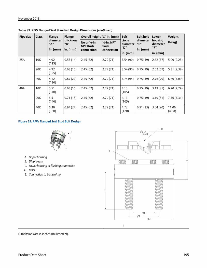
Table 89: RFW Flanged Seal Standard Design Dimensions (continued)
Pipe size Class Flangediameter“A”
in. (mm)
Flangethickness“B”
in. (mm)
Overall height “C” in. (mm) Boltcirclediameter“D”
in. (mm)
Bolt holediameter“E”
in. (mm)
Lowerhousingdiameter“F”
in. (mm)
Weight
lb (kg)No or ¼-in.NPT flushconnection
½-in. NPTflushconnection
25A 10K 4.92(125)
0.55 (14) 2.45 (62) 2.79 (71) 3.54 (90) 0.75 (19) 2.62 (67) 5.00 (2,25)
20K 4.92(125)
0.63 (16) 2.45 (62) 2.79 (71) 3.54 (90) 0.75 (19) 2.62 (67) 5.31 (2,39)
40K 5.12(130)
0.87 (22) 2.45 (62) 2.79 (71) 3.74 (95) 0.75 (19) 2.76 (70) 6.86 (3,09)
40A 10K 5.51(140)
0.63 (16) 2.45 (62) 2.79 (71) 4.13(105)
0.75 (19) 3.19 (81) 6.20 (2,79)
20K 5.51(140)
0.71 (18) 2.45 (62) 2.79 (71) 4.13(105)
0.75 (19) 3.19 (81) 7.36 (3,31)
40K 6.30(160)
0.94 (24) 2.45 (62) 2.79 (71) 4.72(120)
0.91 (23) 3.54 (90) 11.06(4,98)
Figure 29: RFW Flanged Seal Stud Bolt Design
A. Upper housingB. DiaphragmC. Lower housing or flushing connectionD. BoltsE. Connection to transmitter
E
B
Dimensions are in inches (millimeters).
November 2018
Product Data Sheet 195
Table 90: RFW Flanged Seal Stud Bolt Design Dimensions
Pipesize
Class Overall height “A” in.(mm)
Stud circlediameter “B”
in. (mm)
Stud (size,length) “C”
in. (mm)
Lowerhousingdiameter “D”
in. (mm)
Raised facediameter“E”
in. (mm)
Weight
lb (kg)No or ¼-in. NPTflushconnection
½-in. NPTflushconnection
ANSI/ASME
½-in. 150 2.52 (64) 2.82 (72) 2.38 (61) ½–13NC, 2.5-in. 3.74 (95) 1.38 (35) 6.28(2,83)
300/600 2.77 (70) 2.87 (73) 2.62 (67) ½–13NC, 2.5-in. 3.75 (95) 1.38 (35) 6.53(2,94)
¾-in. 150 2.52 (64) 2.82 (72) 2.75 (70) ½–13NC, 2.5-in. 3.88 (99) 1.69 (43) 6.46(2,91)
EN 1092-1
DN 15 PN 40 2.52 (64) 2.82 (72) 2.56 (65) M12 × 1.75, 60mm
3.74 (95) 1.77 (45) 6.27(2,82)
PN100/160
2.52 (64) 2.82 (72) 2.95 (75) M12 × 1.75, 60mm
4.13 (105) 1.77 (45) 6.92(3,11)
DN 20 PN 40 2.52 (64) 2.82 (72) 2.95 (75) M12 × 1.75, 60mm
4.13 (105) 2.28 (58) 6.90(3,11)
JIS
10A 10/20K 2.52 (64) 2.82 (72) 2.56 (65) M12 × 1.75, 60mm
3.74 (95) 1.81 (46) 6.30(2,84)
40K 2.52 (64) 2.82 (72) 2.95 (75) M16 × 2.00, 70mm
4.33 (110) 2.05 (52) 7.70(3,47)
15A 10K 2.52 (64) 2.82 (72) 2.76 (70) M12 × 1.75, 60mm
3.74 (95) 2.01 (51) 6.39(2,88)
20K 2.52 (64) 2.82 (72) 2.76 (70) M12 × 2.00, 60mm
3.74 (95) 2.01 (51) 6.39(2,88)
40K 2.52 (64) 2.82 (72) 3.15 (80) M16 × 2.00, 70mm
4.53 (115) 2.17 (55) 8.26(3,72)
20A 10/20K 2.52 (64) 2.82 (72) 2.95 (75) M12 × 1.75, 60mm
3.94 (100) 2.21 (56) 6.68(3,01)
November 2018
196 Emerson.com/Rosemount
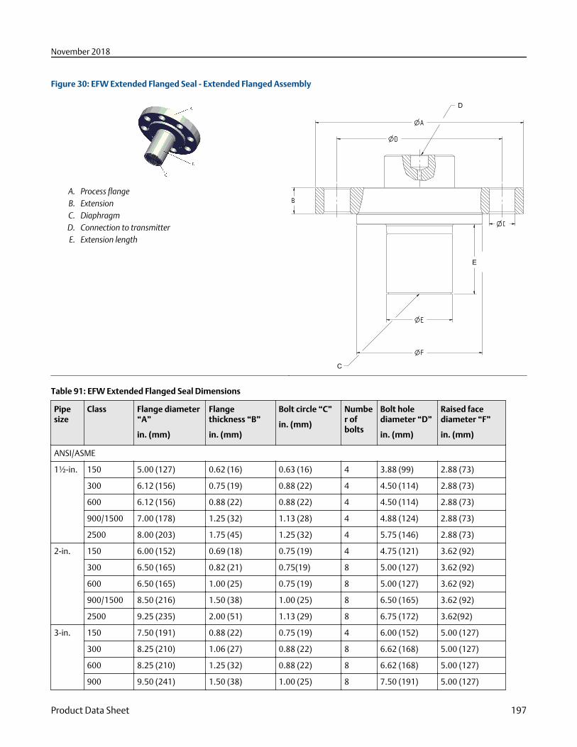
Figure 30: EFW Extended Flanged Seal - Extended Flanged Assembly
A. Process flangeB. ExtensionC. DiaphragmD. Connection to transmitterE. Extension length
D
C
E
Table 91: EFW Extended Flanged Seal Dimensions
Pipesize
Class Flange diameter“A”
in. (mm)
Flangethickness “B”
in. (mm)
Bolt circle “C”
in. (mm)
Number ofbolts
Bolt holediameter “D”
in. (mm)
Raised facediameter “F”
in. (mm)
ANSI/ASME
1½-in. 150 5.00 (127) 0.62 (16) 0.63 (16) 4 3.88 (99) 2.88 (73)
300 6.12 (156) 0.75 (19) 0.88 (22) 4 4.50 (114) 2.88 (73)
600 6.12 (156) 0.88 (22) 0.88 (22) 4 4.50 (114) 2.88 (73)
900/1500 7.00 (178) 1.25 (32) 1.13 (28) 4 4.88 (124) 2.88 (73)
2500 8.00 (203) 1.75 (45) 1.25 (32) 4 5.75 (146) 2.88 (73)
2-in. 150 6.00 (152) 0.69 (18) 0.75 (19) 4 4.75 (121) 3.62 (92)
300 6.50 (165) 0.82 (21) 0.75(19) 8 5.00 (127) 3.62 (92)
600 6.50 (165) 1.00 (25) 0.75 (19) 8 5.00 (127) 3.62 (92)
900/1500 8.50 (216) 1.50 (38) 1.00 (25) 8 6.50 (165) 3.62 (92)
2500 9.25 (235) 2.00 (51) 1.13 (29) 8 6.75 (172) 3.62(92)
3-in. 150 7.50 (191) 0.88 (22) 0.75 (19) 4 6.00 (152) 5.00 (127)
300 8.25 (210) 1.06 (27) 0.88 (22) 8 6.62 (168) 5.00 (127)
600 8.25 (210) 1.25 (32) 0.88 (22) 8 6.62 (168) 5.00 (127)
900 9.50 (241) 1.50 (38) 1.00 (25) 8 7.50 (191) 5.00 (127)
November 2018
Product Data Sheet 197
Table 91: EFW Extended Flanged Seal Dimensions (continued)
Pipesize
Class Flange diameter“A”
in. (mm)
Flangethickness “B”
in. (mm)
Bolt circle “C”
in. (mm)
Number ofbolts
Bolt holediameter “D”
in. (mm)
Raised facediameter “F”
in. (mm)
1500 10.50 (267) 1.88 (48) 1.25(32) 8 8.00 (203) 5.00 (127)
2500 12.00 (305) 2.62 (67) 1.38 (35) 8 9.00 (229) 5.00 (127)
4-in. 150 9.00 (229) 0.88 (22) 0.75 (19) 8 7.50 (191) 6.20 (158)
300 10.00 (254) 1.19 (30) 0.88 (22) 8 7.88 (200) 6.20 (158)
600 10.75 (273) 1.50 (38) 1.00 (25) 8 8.50 (216) 6.20 (158)
900 11.50 (292) 1.75 (45) 1.25 (32) 8 9.25 (235) 6.20 (158)
1500 12.25 (311) 2.12 (54) 1.38 (35) 8 9.50 (241) 6.20 (158)
2500 14.00 (356) 3.00 (76) 1.63 (41) 8 10.75 (274) 6.20 (158)
EN 1092-1
DN 50 PN 40 6.50 (165) 0.67 (17) 0.71 (18) 4 4.92 (125) 4.02 (102)
PN 63 7.08 (180) 0.91 (23) 0.87 (22) 4 5.31 (135) 4.02 (102)
PN 100 7.68 (195) 0.98 (25) 1.02 (26) 4 5.71 (145) 4.02 (102)
PN 160 7.68 (195) 1.06 (27) 1.02 (26) 4 5.71 (145) 4.02 (102)
DN 80 PN 40 7.87 (200) 0.83 (21) 0.71 (18) 8 6.30 (160) 5.43 (138)
PN 63 8.46 (215) 0.98 (25) 0.88 (22) 8 6.69 (170) 5.43 (138)
PN 100 9.06 (230) 1.14 (29) 1.02 (26) 8 7.09 (180) 5.43 (138)
PN 160 9.06 (230) 1.30 (33) 1.02 (26) 8 7.09 (180) 5.43 (138)
DN100
PN 10/16 8.66 (220) 0.67 (17) 0.71 (18) 8 7.09 (180) 6.20 (158)
PN 40 9.25 (235) 0.83 (21) 0.87 (22) 8 7.48 (190) 6.20 (158)
PN 63 9.84 (250) 1.06 (27) 1.02 (26) 8 7.87 (200) 6.20 (158)
PN 100 10.43 (265) 1.30 (33) 1.18 (30) 8 8.27 (210) 6.20 (158)
PN 160 10.43 (265) 1.46 (37) 1.18 (30) 8 8.27 (210) 6.20 (158)
JIS
50A 10K 6.10 (155) 0.63 (16) 0.75 (19) 4 4.72 (120) 3.62 (92)
20K 6.10 (155) 0.71 (18) 0.75 (19) 8 4.72 (120) 3.62 (92)
40K 6.50 (165) 1.02 (26) 0.75 (19) 8 5.12 (130) 4.00 (102)
80A 10K 7.28 (185) 0.71 (18) 0.75 (19) 8 5.91 (150) 5.00 (127)
20K 7.87 (200) 0.87 (22) 0.91 (23) 8 6.30 (160) 5.00 (127)
40K 8.27 (210) 1.26 (32) 0.91 (23) 8 6.69 (170) 5.43 (138)
100A 10K 8.27 (210) 0.71 (18) 0.75 (19) 8 6.89 (175) 6.20 (158)
20K 8.86 (225) 0.94 (24) 0.91 (23) 8 7.28 (185) 6.20 (158)
40K 9.84 (250) 1.42 (36) 0.98 (25) 8 8.07 (205) 6.20 (158)
November 2018
198 Emerson.com/Rosemount
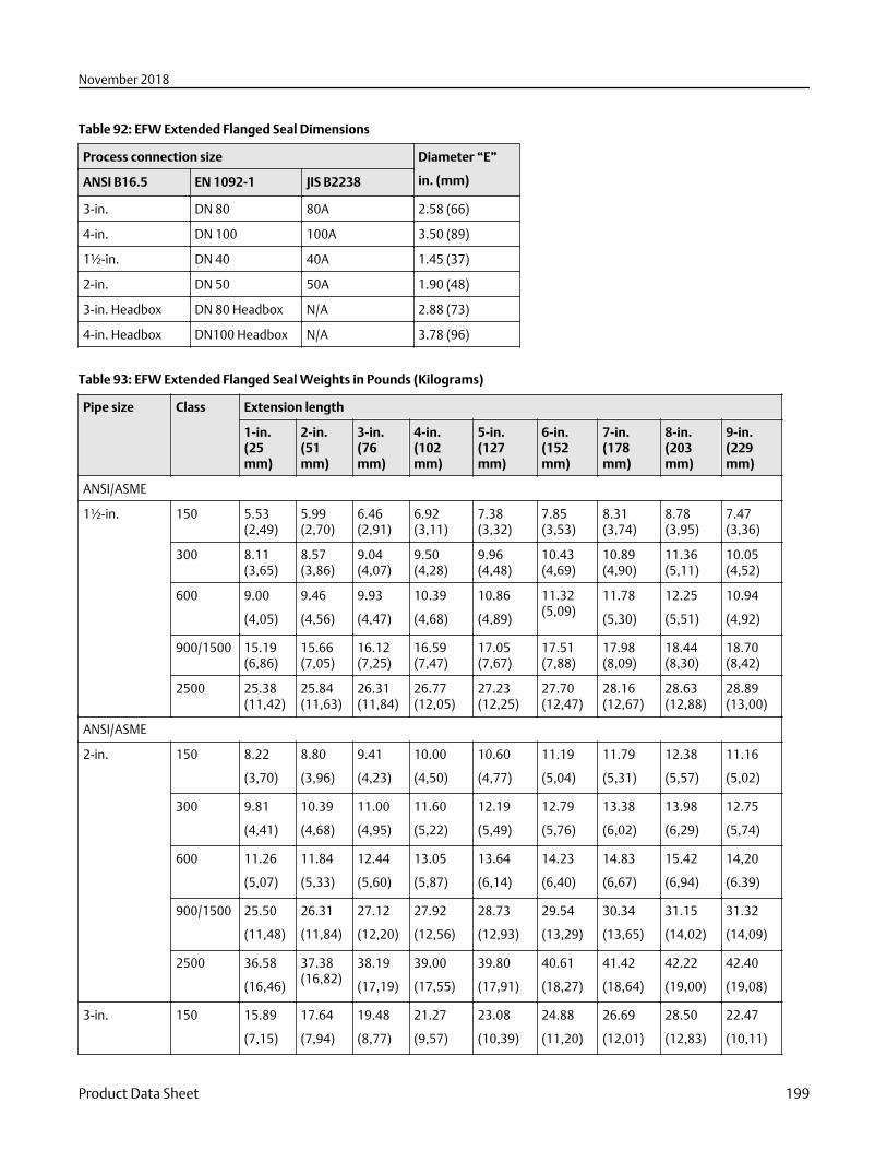
Table 92: EFW Extended Flanged Seal Dimensions
Process connection size Diameter “E”
in. (mm)ANSI B16.5 EN 1092-1 JIS B2238
3-in. DN 80 80A 2.58 (66)
4-in. DN 100 100A 3.50 (89)
1½-in. DN 40 40A 1.45 (37)
2-in. DN 50 50A 1.90 (48)
3-in. Headbox DN 80 Headbox N/A 2.88 (73)
4-in. Headbox DN100 Headbox N/A 3.78 (96)
Table 93: EFW Extended Flanged Seal Weights in Pounds (Kilograms)
Pipe size Class Extension length
1-in.(25mm)
2-in.(51mm)
3-in.(76mm)
4-in.(102mm)
5-in.(127mm)
6-in.(152mm)
7-in.(178mm)
8-in.(203mm)
9-in.(229mm)
ANSI/ASME
1½-in. 150 5.53(2,49)
5.99(2,70)
6.46(2,91)
6.92(3,11)
7.38(3,32)
7.85(3,53)
8.31(3,74)
8.78(3,95)
7.47(3,36)
300 8.11(3,65)
8.57(3,86)
9.04(4,07)
9.50(4,28)
9.96(4,48)
10.43(4,69)
10.89(4,90)
11.36(5,11)
10.05(4,52)
600 9.00
(4,05)
9.46
(4,56)
9.93
(4,47)
10.39
(4,68)
10.86
(4,89)
11.32(5,09)
11.78
(5,30)
12.25
(5,51)
10.94
(4,92)
900/1500 15.19(6,86)
15.66(7,05)
16.12(7,25)
16.59(7,47)
17.05(7,67)
17.51(7,88)
17.98(8,09)
18.44(8,30)
18.70(8,42)
2500 25.38(11,42)
25.84(11,63)
26.31(11,84)
26.77(12,05)
27.23(12,25)
27.70(12,47)
28.16(12,67)
28.63(12,88)
28.89(13,00)
ANSI/ASME
2-in. 150 8.22
(3,70)
8.80
(3,96)
9.41
(4,23)
10.00
(4,50)
10.60
(4,77)
11.19
(5,04)
11.79
(5,31)
12.38
(5,57)
11.16
(5,02)
300 9.81
(4,41)
10.39
(4,68)
11.00
(4,95)
11.60
(5,22)
12.19
(5,49)
12.79
(5,76)
13.38
(6,02)
13.98
(6,29)
12.75
(5,74)
600 11.26
(5,07)
11.84
(5,33)
12.44
(5,60)
13.05
(5,87)
13.64
(6,14)
14.23
(6,40)
14.83
(6,67)
15.42
(6,94)
14,20
(6.39)
900/1500 25.50
(11,48)
26.31
(11,84)
27.12
(12,20)
27.92
(12,56)
28.73
(12,93)
29.54
(13,29)
30.34
(13,65)
31.15
(14,02)
31.32
(14,09)
2500 36.58
(16,46)
37.38(16,82)
38.19
(17,19)
39.00
(17,55)
39.80
(17,91)
40.61
(18,27)
41.42
(18,64)
42.22
(19,00)
42.40
(19,08)
3-in. 150 15.89
(7,15)
17.64
(7,94)
19.48
(8,77)
21.27
(9,57)
23.08
(10,39)
24.88
(11,20)
26.69
(12,01)
28.50
(12,83)
22.47
(10,11)
November 2018
Product Data Sheet 199
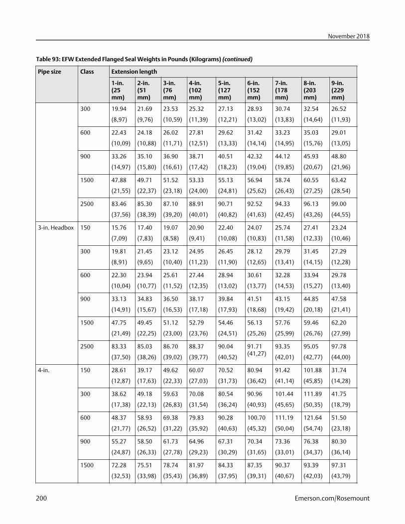
Table 93: EFW Extended Flanged Seal Weights in Pounds (Kilograms) (continued)
Pipe size Class Extension length
1-in.(25mm)
2-in.(51mm)
3-in.(76mm)
4-in.(102mm)
5-in.(127mm)
6-in.(152mm)
7-in.(178mm)
8-in.(203mm)
9-in.(229mm)
300 19.94
(8,97)
21.69
(9,76)
23.53
(10,59)
25.32
(11,39)
27.13
(12,21)
28.93
(13,02)
30.74
(13,83)
32.54
(14,64)
26.52
(11,93)
600 22.43
(10,09)
24.18
(10,88)
26.02
(11,71)
27.81
(12,51)
29.62
(13,33)
31.42
(14,14)
33.23
(14,95)
35.03
(15,76)
29.01
(13,05)
900 33.26
(14,97)
35.10
(15,80)
36.90
(16,61)
38.71
(17,42)
40.51
(18,23)
42.32
(19,04)
44.12
(19,85)
45.93
(20,67)
48.80
(21,96)
1500 47.88
(21,55)
49.71
(22,37)
51.52
(23,18)
53.33
(24,00)
55.13
(24,81)
56.94
(25,62)
58.74
(26,43)
60.55
(27,25)
63.42
(28,54)
2500 83.46
(37,56)
85.30
(38,39)
87.10
(39,20)
88.91
(40,01)
90.71
(40,82)
92.52
(41,63)
94.33
(42,45)
96.13
(43,26)
99.00
(44,55)
3-in. Headbox 150 15.76
(7,09)
17.40
(7,83)
19.07
(8,58)
20.90
(9,41)
22.40
(10,08)
24.07
(10,83)
25.74
(11,58)
27.41
(12,33)
23.24
(10,46)
300 19.81
(8,91)
21.45
(9,65)
23.12
(10,40)
24.95
(11,23)
26.45
(11,90)
28.12
(12,65)
29.79
(13,41)
31.45
(14,15)
27.29
(12,28)
600 22.30
(10,04)
23.94
(10,77)
25.61
(11,52)
27.44
(12,35)
28.94
(13,02)
30.61
(13,77)
32.28
(14,53)
33.94
(15,27)
29.78
(13,40)
900 33.13
(14,91)
34.83
(15,67)
36.50
(16,53)
38.17
(17,18)
39.84
(17,93)
41.51
(18,68)
43.15
(19,42)
44.85
(20,18)
47.58
(21,41)
1500 47.75
(21,49)
49.45
(22,25)
51.12
(23,00)
52.79
(23,76)
54.46
(24,51)
56.13
(25,26)
57.76
(25,99)
59.46
(26,76)
62.20
(27,99)
2500 83.33
(37,50)
85.03
(38,26)
86.70
(39,02)
88.37
(39,77)
90.04
(40,52)
91.71(41,27)
93.35
(42,01)
95.05
(42,77)
97.78
(44,00)
4-in. 150 28.61
(12,87)
39.17
(17,63)
49.62
(22,33)
60.07
(27,03)
70.52
(31,73)
80.94
(36,42)
91.42
(41,14)
101.88
(45,85)
31.74
(14,28)
300 38.62
(17,38)
49.18
(22,13)
59.63
(26,83)
70.08
(31,54)
80.54
(36,24)
90.96
(40,93)
101.44
(45,65)
111.89
(50,35)
41.75
(18,79)
600 48.37
(21,77)
58.93
(26,52)
69.38
(31,22)
79.83
(35,92)
90.28
(40,63)
100.70
(45,32)
111.19
(50,04)
121.64
(54,74)
51.50
(23,18)
900 55.27
(24,87)
58.50
(26,33)
61.73
(27,78)
64.96
(29,23)
67.31
(30,29)
70.34
(31,65)
73.36
(33,01)
76.38
(34,37)
80.30
(36,14)
1500 72.28
(32,53)
75.51
(33,98)
78.74
(35,43)
81.97
(36,89)
84.33
(37,95)
87.35
(39,31)
90.37
(40,67)
93.39
(42,03)
97.31
(43,79)
November 2018
200 Emerson.com/Rosemount
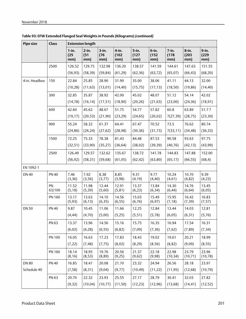
Table 93: EFW Extended Flanged Seal Weights in Pounds (Kilograms) (continued)
Pipe size Class Extension length
1-in.(25mm)
2-in.(51mm)
3-in.(76mm)
4-in.(102mm)
5-in.(127mm)
6-in.(152mm)
7-in.(178mm)
8-in.(203mm)
9-in.(229mm)
2500 126.52
(56,93)
129.75
(58,39)
132.98
(59,84)
136.20
(61,29)
138.57
(62,36)
141.59
(63,72)
144.61
(65,07)
147.63
(66,43)
151.55
(68,20)
4-in. Headbox 150 22.84
(10,28)
25.85
(11,63)
28.90
(13,01)
31.99
(14,40)
35.00
(15,75)
38.06
(17,13)
41.11
(18,50)
44.13
(19,86)
32.00
(14,40)
300 32.85
(14,78)
35.87
(16,14)
38.92
(17,51)
42.00
(18,90)
45.02
(20,26)
48.07
(21,63)
51.12
(23,00)
54.14
(24,36)
42.02
(18,91)
600 42.60
(19,17)
45.62
(20,53)
48.67
(21,90)
51.75
(23,29)
54.77
(24,65)
57.82
(26,02)
60.8
7(27,39)
63.89
(28,75)
51.7 7
(23,30)
900 55.24
(24,86)
58.32
(26,24)
61.37
(27,62)
64.41
(28,98)
67.47
(30,36)
70.52
(31,73)
73.5
7(33,11)
76.62
(34,48)
80.74
(36,33)
1500 72.25
(32,51)
75.33
(33,90)
78.38
(35,27)
81.43
(36,64)
84.48
(38,02)
87.53
(39,39)
90.58
(40,76)
93.63
(42,13)
97.75
(43,99)
2500 126.49
(56,92)
129.57
(58,31)
132.62
(59,68)
135.67
(61,05)
138.72
(62,42)
141.78
(63,80)
144.83
(65,17)
147.88
(66,55)
152.00
(68,4)
EN 1092-1
DN 40 PN 40 7.46(3,36)
7.92(3,56)
8.38(3,77)
8.85(3,98)
9.31(4,19)
9.77(4,40)
10.24(4,61)
10.70(4,82)
9.39(4,23)
PN63/100
11.52(5,18)
11.98(5,39)
12.44(5,60)
12.91(5,81)
13.37(6,23)
13.84(6,34)
14.30(6,44)
14.76(6,64)
13.45(6,05)
PN 160 13.17(5,93)
13.63(6,13)
14.10(6,35)
14.56(6,55)
15.03(6,76)
15.49(6,97)
15.95(7,18)
16.42(7,39)
16.83(7,57)
DN 50 PN 40 9.87
(4,44)
10.45
(4,70)
11.06
(5,00)
11.66
(5,25)
12.25
(5,51)
12.84
(5,78)
13.44
(6,05)
14.03
(6,31)
12.81
(5,76)
PN 63 13.37
(6,02)
13.96
(6,28)
14.56
(6,55)
15.16
(6,82)
15.75
(7,09)
16.35
(7,36)
16.94
(7,62)
17.54
(7,89)
16.31
(7,34)
PN 100 16.05
(7,22)
16.63
(7,48)
17.23
(7,75)
17.83
(8,02)
18.43
(8,29)
19.02
(8,56)
19.61
(8,82)
20.21
(9,09)
18.99
(8,55)
PN 160 18.14(8,16)
18.95(8,53)
19.76(8,89)
20.56(9,25)
21.37(9,62)
22.18(9,98)
22.98(10,34)
23.79(10,71)
23.96(10,78)
DN 80
Schedule 40
PN 40 16.85
(7,58)
18.47
(8,31)
20.08
(9,04)
21.70
(9,77)
23.32
(10,49)
24.94
(11,22)
26.56
(11,95)
28.18
(12,68)
23.97
(10,79)
PN 63 20.70
(9,32)
22.32
(10,04)
23.93
(10,77)
25.55
(11,50)
27.17
(12,23)
28.79
(12,96)
30.41
(13,68)
32.03
(14,41)
27.82
(12,52)
November 2018
Product Data Sheet 201
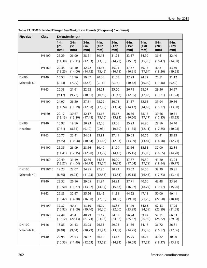
Table 93: EFW Extended Flanged Seal Weights in Pounds (Kilograms) (continued)
Pipe size Class Extension length
1-in.(25mm)
2-in.(51mm)
3-in.(76mm)
4-in.(102mm)
5-in.(127mm)
6-in.(152mm)
7-in.(178mm)
8-in.(203mm)
9-in.(229mm)
PN 100 25.29
(11,38)
26.90
(12,11)
28.51
(12,83)
30.13
(13,56)
31.75
(14,29)
33.37
(15,02)
34.99
(15,75)
36.61
(16,47)
32.40
(14,58)
PN 160 29.45(13,25)
31.10(14,00)
32.72(14,72)
34.33(15,45)
35.95(16,18)
37.57(16,91)
39.17(17,64)
40.81(18,36)
43.50(19,58)
DN 80
Schedule 80
PN 40 16.53
(7,44)
17.76
(7,99)
19.07
(8,58)
20.36
(9,16)
21.65
(9,74)
22.93
(10,32)
24.22
(10,90)
25.51
(11,48)
21.12
(9,50)
PN 63 20.38
(9,17)
21.61
(9,72)
22.92
(10,31)
24.21
(10,89)
25.50
(11,48)
26.78
(12,05)
28.07
(12,63)
29.36
(13,21)
24.97
(11,24)
PN 100 24.97
(11,24)
26.20
(11,79)
27.51
(12,38)
28.79
(12,96)
30.08
(13,54)
31.37
(14,12)
32.65
(14,69)
33.94
(15,27)
29.56
(13,30)
PN160 29.17(13,13)
30.67(13,80)
32.17(17,48)
33.67(15,15)
35.17(15,83)
36.66(16,50)
38.16(17,17)
39.66(17,85)
40.51(18,23)
DN 80
Headbox
PN 40 16.92
(7,61)
18.56
(8,35)
20.23
(9,10)
22,06
(9,93)
23.56
(10,60)
25.23
(11,35)
26.90
(12,11)
28.56
(12,85)
24.40
(10,98)
PN 63 20.77
(9,35)
22.41
(10,08)
24.08
(10,84)
25.91
(11,66)
27.41
(12,33)
29.08
(13,09)
30.75
(13,84)
32.41
(14,58)
28.25
(12,71)
PN 100 25.35
(11,41)
26.99
(12,15)
28.66
(12,90)
30.49
(13,72)
31.99
(14,40)
33.66
(15,15)
35.33
(15,90)
37.00
(16,65)
32.84
(14,78)
PN 160 29.49(13,27)
31.19(14,04)
32.86(14,79)
34.53(15,54)
36.20(16,29)
37.87(17,04)
39.50(17,78)
41.20(18,54)
43.94(19,77)
DN 100
Schedule 40
PN 10/16 19.23
(8,65)
22.07
(9,93)
24.95
(11,23)
27.85
(12,53)
30.73
(13,83)
33.62
(15,13)
36.50
(16,43)
39.39
(17,73)
29.81
(13,41)
PN 40 23.32
(10,50)
26.16
(11,77)
29.05
(13,07)
31.94
(14,37)
34.83
(15,67)
37.71
(16,97)
40.60
(18,27)
43.48
(19,57)
33.90
(15,26)
PN 63 29.83
(13,42)
32.67
(14,70)
35.56
(16,00)
38.45
(17,30)
41.34
(18,60)
44.22
(19,90)
47.11
(21,20)
50.00
(22,50)
40.41
(18,18)
PN 100 37.37(16,82)
40.21(18,09)
43.10(19,40)
45.99(20,70)
48.88(22,00)
51.76(23,29)
54.65(24,59)
57.53(25,89)
47.95(21,58)
PN 160 42,48(19,12)
45.4(20,43)
48.29(21,73)
51.17(23,03)
54.05(24,32)
56.94(25,62)
59.82(26,92)
52.71(28,22)
66.63(29,98)
DN 100
Schedule 80
PN 16 18.85
(8,48)
21.43
(9,64)
23.98
(10,79)
26.53
(11,94)
29.08
(13,09)
31.66
(14,25)
34.17
(15,38)
36.72
(16,52)
26.81
(12,06)
PN 40 22.95
(10,33)
25.53
(11,49)
28.07
(12,63)
30.62
(13,78)
33.17
(14,93)
35.75
(16,09)
38.27
(17,22)
40.82
(18,37)
30.90
(13,91)
November 2018
202 Emerson.com/Rosemount
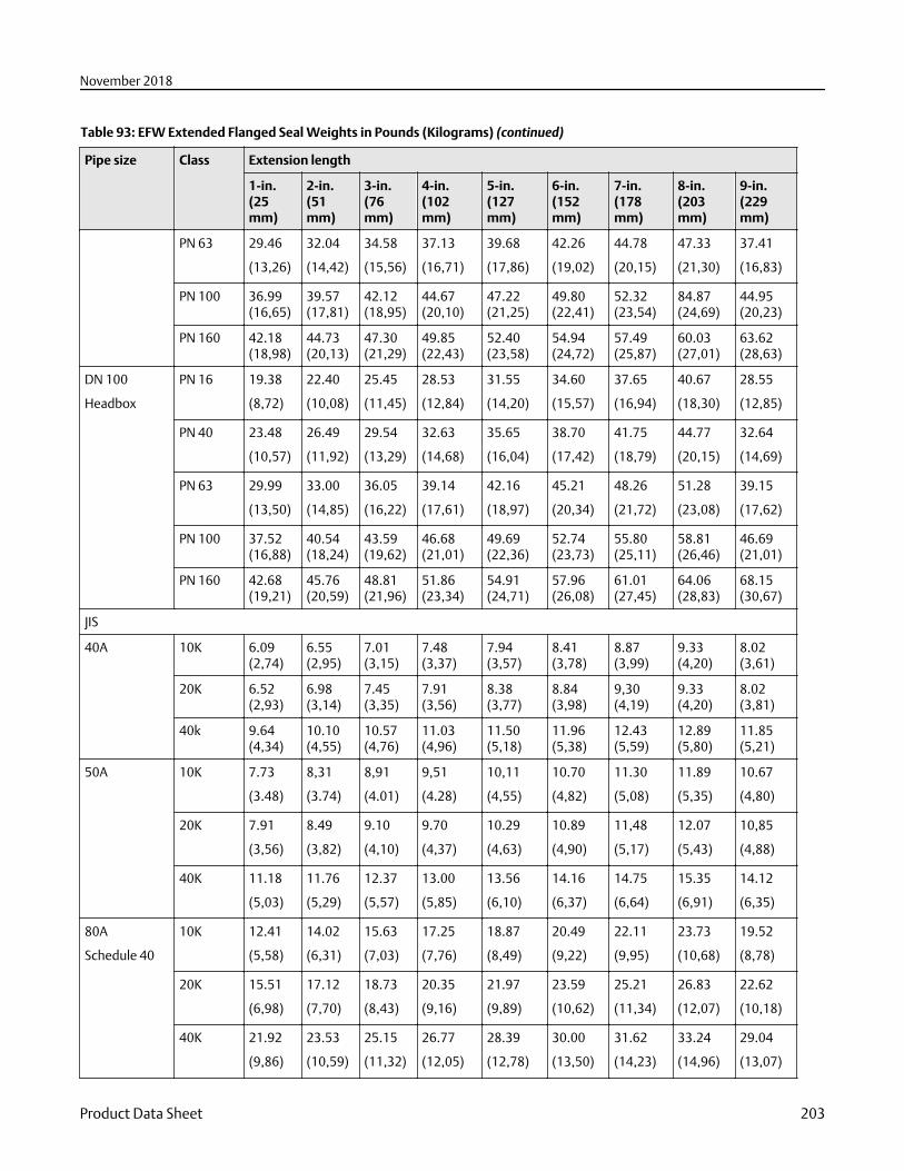
Table 93: EFW Extended Flanged Seal Weights in Pounds (Kilograms) (continued)
Pipe size Class Extension length
1-in.(25mm)
2-in.(51mm)
3-in.(76mm)
4-in.(102mm)
5-in.(127mm)
6-in.(152mm)
7-in.(178mm)
8-in.(203mm)
9-in.(229mm)
PN 63 29.46
(13,26)
32.04
(14,42)
34.58
(15,56)
37.13
(16,71)
39.68
(17,86)
42.26
(19,02)
44.78
(20,15)
47.33
(21,30)
37.41
(16,83)
PN 100 36.99(16,65)
39.57(17,81)
42.12(18,95)
44.67(20,10)
47.22(21,25)
49.80(22,41)
52.32(23,54)
84.87(24,69)
44.95(20,23)
PN 160 42.18(18,98)
44.73(20,13)
47.30(21,29)
49.85(22,43)
52.40(23,58)
54.94(24,72)
57.49(25,87)
60.03(27,01)
63.62(28,63)
DN 100
Headbox
PN 16 19.38
(8,72)
22.40
(10,08)
25.45
(11,45)
28.53
(12,84)
31.55
(14,20)
34.60
(15,57)
37.65
(16,94)
40.67
(18,30)
28.55
(12,85)
PN 40 23.48
(10,57)
26.49
(11,92)
29.54
(13,29)
32.63
(14,68)
35.65
(16,04)
38.70
(17,42)
41.75
(18,79)
44.77
(20,15)
32.64
(14,69)
PN 63 29.99
(13,50)
33.00
(14,85)
36.05
(16,22)
39.14
(17,61)
42.16
(18,97)
45.21
(20,34)
48.26
(21,72)
51.28
(23,08)
39.15
(17,62)
PN 100 37.52(16,88)
40.54(18,24)
43.59(19,62)
46.68(21,01)
49.69(22,36)
52.74(23,73)
55.80(25,11)
58.81(26,46)
46.69(21,01)
PN 160 42.68(19,21)
45.76(20,59)
48.81(21,96)
51.86(23,34)
54.91(24,71)
57.96(26,08)
61.01(27,45)
64.06(28,83)
68.15(30,67)
JIS
40A 10K 6.09(2,74)
6.55(2,95)
7.01(3,15)
7.48(3,37)
7.94(3,57)
8.41(3,78)
8.87(3,99)
9.33(4,20)
8.02(3,61)
20K 6.52(2,93)
6.98(3,14)
7.45(3,35)
7.91(3,56)
8.38(3,77)
8.84(3,98)
9,30(4,19)
9.33(4,20)
8.02(3,81)
40k 9.64(4,34)
10.10(4,55)
10.57(4,76)
11.03(4,96)
11.50(5,18)
11.96(5,38)
12.43(5,59)
12.89(5,80)
11.85(5,21)
50A 10K 7.73
(3.48)
8,31
(3.74)
8,91
(4.01)
9,51
(4.28)
10,11
(4,55)
10.70
(4,82)
11.30
(5,08)
11.89
(5,35)
10.67
(4,80)
20K 7.91
(3,56)
8.49
(3,82)
9.10
(4,10)
9.70
(4,37)
10.29
(4,63)
10.89
(4,90)
11,48
(5,17)
12.07
(5,43)
10,85
(4,88)
40K 11.18
(5,03)
11.76
(5,29)
12.37
(5,57)
13.00
(5,85)
13.56
(6,10)
14.16
(6,37)
14.75
(6,64)
15.35
(6,91)
14.12
(6,35)
80A
Schedule 40
10K 12.41
(5,58)
14.02
(6,31)
15.63
(7,03)
17.25
(7,76)
18.87
(8,49)
20.49
(9,22)
22.11
(9,95)
23.73
(10,68)
19.52
(8,78)
20K 15.51
(6,98)
17.12
(7,70)
18.73
(8,43)
20.35
(9,16)
21.97
(9,89)
23.59
(10,62)
25.21
(11,34)
26.83
(12,07)
22.62
(10,18)
40K 21.92
(9,86)
23.53
(10,59)
25.15
(11,32)
26.77
(12,05)
28.39
(12,78)
30.00
(13,50)
31.62
(14,23)
33.24
(14,96)
29.04
(13,07)
November 2018
Product Data Sheet 203
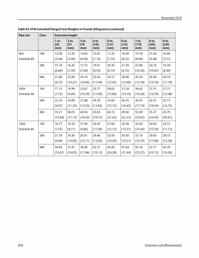
Table 93: EFW Extended Flanged Seal Weights in Pounds (Kilograms) (continued)
Pipe size Class Extension length
1-in.(25mm)
2-in.(51mm)
3-in.(76mm)
4-in.(102mm)
5-in.(127mm)
6-in.(152mm)
7-in.(178mm)
8-in.(203mm)
9-in.(229mm)
80A
Schedule 80
10K 12.09
(5,44)
13.32
(5,99)
14.63
(6,58)
15.91
(7,16)
17.20
(7,74)
18.49
(8,32)
19.78
(8,90)
21.06
(9,48)
16.68
(7,51)
20K 15.19
(6,84)
16.42
(7,39)
17.73
(7,98)
19.01
(8,55)
20.30
(9,14)
21.59
(9,72)
22.88
(10,30)
24.16
(10,87)
19.78
(8,90)
40K 21.60
(9,72)
22.83
(10,27)
24.14
(10,86)
25.43
(11,44)
26.72
(12,02)
28.00
(12,60)
29.29
(13,18)
30.58
(13,76)
26.19
(11,79)
100A
Schedule 40
10K 17.15
(7,72)
19.99
(9,00)
22.87
(10,29)
25.77
(11,60)
28.65
(12,89)
31.54
(14,19)
34.42
(15,49)
37.31
(16,79)
27.73
(12,48)
20K 22.16
(9,97)
24.99
(11,25)
27.88
(12,55)
30.78
(13,85)
33.66
(15,15)
36.55
(16,45)
39.43
(17,74)
42.31
(19,04)
32.73
(14,73)
40K 35.21
(15,84)
38.05
(17,12)
40.94
(18,42)
43.83
(19,72)
46.72
(21,02)
49.60
(22,32)
52.49
(23,62)
55.37
(24,92)
45.79
(20,61)
100A
Schedule 80
10K 16.77
(7,55)
19.35
(8,71)
21.90
(9,86)
24.45
(11,00)
27.00
(12,15)
29.58
(13,31)
32.09
(14,44)
34.64
(15,59)
24.73
(11,13)
20K 21.78
(9,80)
24.36
(10,96)
26.91
(12,11)
29.46
(13,26)
32.00
(14,40)
34.59
(15,57)
37.10
(16,70)
39.65
(17,84)
29.73
(13,38)
40K 34.83
(15,67)
37.41
(16,83)
39.96
(17,98)
42.51
(19,13)
45.06
(20,28)
47.64
(21,44)
50.16
(22,57)
52.71
(23,72)
42.79
(19,26)
November 2018
204 Emerson.com/Rosemount
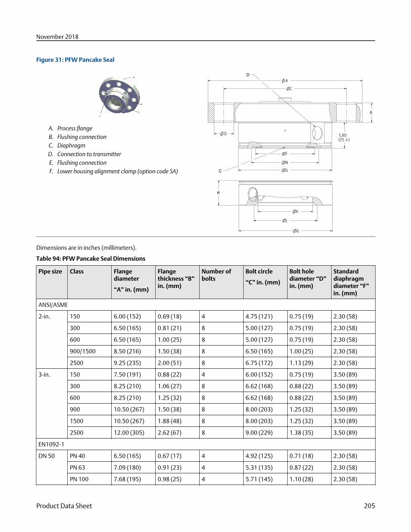
Figure 31: PFW Pancake Seal
A. Process flangeB. Flushing connectionC. DiaphragmD. Connection to transmitterE. Flushing connectionF. Lower housing alignment clamp (option code SA)
D
D
C
Dimensions are in inches (millimeters).
Table 94: PFW Pancake Seal Dimensions
Pipe size Class Flangediameter
“A” in. (mm)
Flangethickness “B”in. (mm)
Number ofbolts
Bolt circle
“C” in. (mm)
Bolt holediameter “D”in. (mm)
Standarddiaphragmdiameter “F”in. (mm)
ANSI/ASME
2-in. 150 6.00 (152) 0.69 (18) 4 4.75 (121) 0.75 (19) 2.30 (58)
300 6.50 (165) 0.81 (21) 8 5.00 (127) 0.75 (19) 2.30 (58)
600 6.50 (165) 1.00 (25) 8 5.00 (127) 0.75 (19) 2.30 (58)
900/1500 8.50 (216) 1.50 (38) 8 6.50 (165) 1.00 (25) 2.30 (58)
2500 9.25 (235) 2.00 (51) 8 6.75 (172) 1.13 (29) 2.30 (58)
3-in. 150 7.50 (191) 0.88 (22) 4 6.00 (152) 0.75 (19) 3.50 (89)
300 8.25 (210) 1.06 (27) 8 6.62 (168) 0.88 (22) 3.50 (89)
600 8.25 (210) 1.25 (32) 8 6.62 (168) 0.88 (22) 3.50 (89)
900 10.50 (267) 1.50 (38) 8 8.00 (203) 1.25 (32) 3.50 (89)
1500 10.50 (267) 1.88 (48) 8 8.00 (203) 1.25 (32) 3.50 (89)
2500 12.00 (305) 2.62 (67) 8 9.00 (229) 1.38 (35) 3.50 (89)
EN1092-1
DN 50 PN 40 6.50 (165) 0.67 (17) 4 4.92 (125) 0.71 (18) 2.30 (58)
PN 63 7.09 (180) 0.91 (23) 4 5.31 (135) 0.87 (22) 2.30 (58)
PN 100 7.68 (195) 0.98 (25) 4 5.71 (145) 1.10 (28) 2.30 (58)
November 2018
Product Data Sheet 205
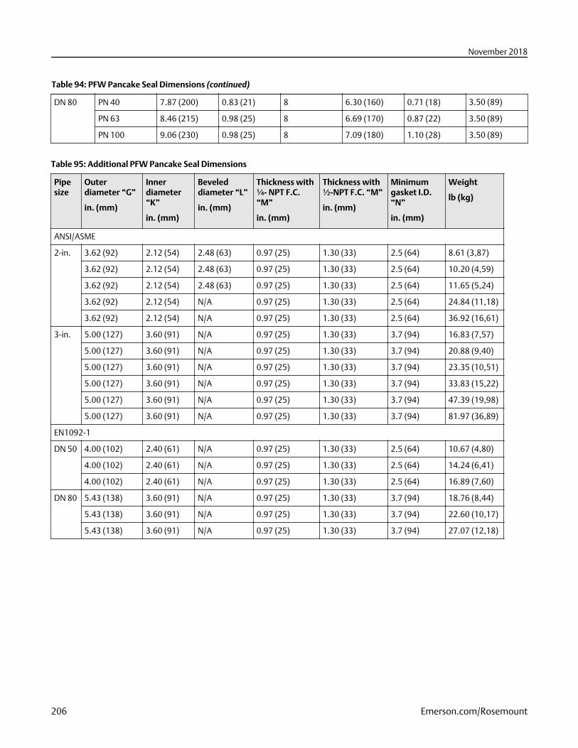
Table 94: PFW Pancake Seal Dimensions (continued)
DN 80 PN 40 7.87 (200) 0.83 (21) 8 6.30 (160) 0.71 (18) 3.50 (89)
PN 63 8.46 (215) 0.98 (25) 8 6.69 (170) 0.87 (22) 3.50 (89)
PN 100 9.06 (230) 0.98 (25) 8 7.09 (180) 1.10 (28) 3.50 (89)
Table 95: Additional PFW Pancake Seal Dimensions
Pipesize
Outerdiameter “G”
in. (mm)
Innerdiameter“K”
in. (mm)
Beveleddiameter “L”
in. (mm)
Thickness with¼- NPT F.C.“M”
in. (mm)
Thickness with½-NPT F.C. “M”
in. (mm)
Minimumgasket I.D.“N”
in. (mm)
Weight
lb (kg)
ANSI/ASME
2-in. 3.62 (92) 2.12 (54) 2.48 (63) 0.97 (25) 1.30 (33) 2.5 (64) 8.61 (3,87)
3.62 (92) 2.12 (54) 2.48 (63) 0.97 (25) 1.30 (33) 2.5 (64) 10.20 (4,59)
3.62 (92) 2.12 (54) 2.48 (63) 0.97 (25) 1.30 (33) 2.5 (64) 11.65 (5,24)
3.62 (92) 2.12 (54) N/A 0.97 (25) 1.30 (33) 2.5 (64) 24.84 (11,18)
3.62 (92) 2.12 (54) N/A 0.97 (25) 1.30 (33) 2.5 (64) 36.92 (16,61)
3-in. 5.00 (127) 3.60 (91) N/A 0.97 (25) 1.30 (33) 3.7 (94) 16.83 (7,57)
5.00 (127) 3.60 (91) N/A 0.97 (25) 1.30 (33) 3.7 (94) 20.88 (9,40)
5.00 (127) 3.60 (91) N/A 0.97 (25) 1.30 (33) 3.7 (94) 23.35 (10,51)
5.00 (127) 3.60 (91) N/A 0.97 (25) 1.30 (33) 3.7 (94) 33.83 (15,22)
5.00 (127) 3.60 (91) N/A 0.97 (25) 1.30 (33) 3.7 (94) 47.39 (19,98)
5.00 (127) 3.60 (91) N/A 0.97 (25) 1.30 (33) 3.7 (94) 81.97 (36,89)
EN1092-1
DN 50 4.00 (102) 2.40 (61) N/A 0.97 (25) 1.30 (33) 2.5 (64) 10.67 (4,80)
4.00 (102) 2.40 (61) N/A 0.97 (25) 1.30 (33) 2.5 (64) 14.24 (6,41)
4.00 (102) 2.40 (61) N/A 0.97 (25) 1.30 (33) 2.5 (64) 16.89 (7,60)
DN 80 5.43 (138) 3.60 (91) N/A 0.97 (25) 1.30 (33) 3.7 (94) 18.76 (8,44)
5.43 (138) 3.60 (91) N/A 0.97 (25) 1.30 (33) 3.7 (94) 22.60 (10,17)
5.43 (138) 3.60 (91) N/A 0.97 (25) 1.30 (33) 3.7 (94) 27.07 (12,18)
November 2018
206 Emerson.com/Rosemount
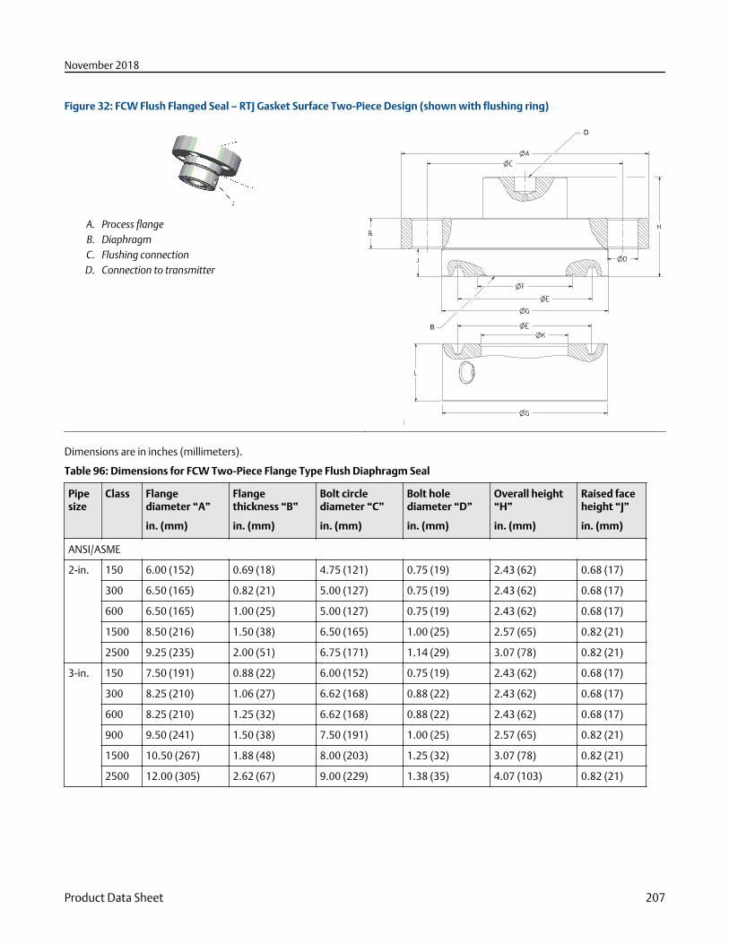
Figure 32: FCW Flush Flanged Seal – RTJ Gasket Surface Two-Piece Design (shown with flushing ring)
A. Process flangeB. DiaphragmC. Flushing connectionD. Connection to transmitter
B
D
Dimensions are in inches (millimeters).
Table 96: Dimensions for FCW Two-Piece Flange Type Flush Diaphragm Seal
Pipesize
Class Flangediameter “A”
in. (mm)
Flangethickness “B”
in. (mm)
Bolt circlediameter “C”
in. (mm)
Bolt holediameter “D”
in. (mm)
Overall height“H”
in. (mm)
Raised faceheight “J”
in. (mm)
ANSI/ASME
2-in. 150 6.00 (152) 0.69 (18) 4.75 (121) 0.75 (19) 2.43 (62) 0.68 (17)
300 6.50 (165) 0.82 (21) 5.00 (127) 0.75 (19) 2.43 (62) 0.68 (17)
600 6.50 (165) 1.00 (25) 5.00 (127) 0.75 (19) 2.43 (62) 0.68 (17)
1500 8.50 (216) 1.50 (38) 6.50 (165) 1.00 (25) 2.57 (65) 0.82 (21)
2500 9.25 (235) 2.00 (51) 6.75 (171) 1.14 (29) 3.07 (78) 0.82 (21)
3-in. 150 7.50 (191) 0.88 (22) 6.00 (152) 0.75 (19) 2.43 (62) 0.68 (17)
300 8.25 (210) 1.06 (27) 6.62 (168) 0.88 (22) 2.43 (62) 0.68 (17)
600 8.25 (210) 1.25 (32) 6.62 (168) 0.88 (22) 2.43 (62) 0.68 (17)
900 9.50 (241) 1.50 (38) 7.50 (191) 1.00 (25) 2.57 (65) 0.82 (21)
1500 10.50 (267) 1.88 (48) 8.00 (203) 1.25 (32) 3.07 (78) 0.82 (21)
2500 12.00 (305) 2.62 (67) 9.00 (229) 1.38 (35) 4.07 (103) 0.82 (21)
November 2018
Product Data Sheet 207
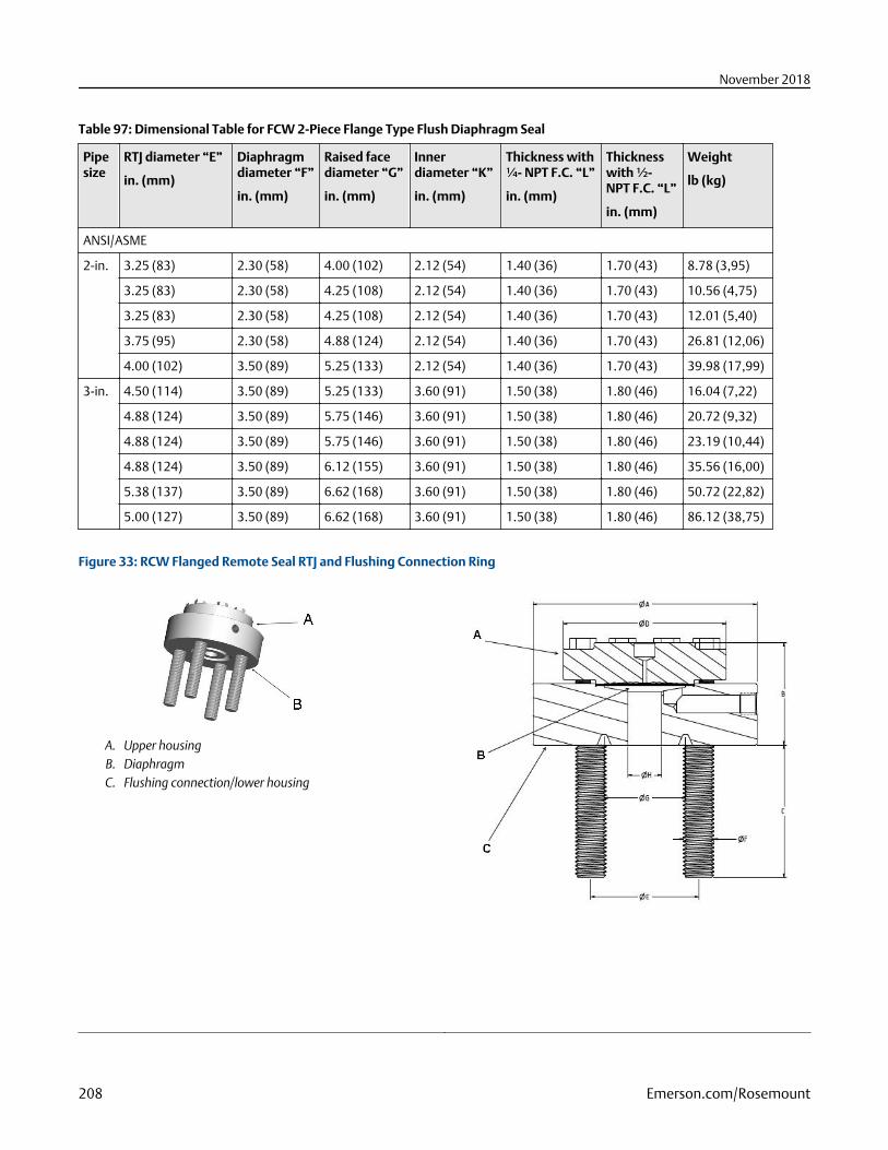
Table 97: Dimensional Table for FCW 2-Piece Flange Type Flush Diaphragm Seal
Pipesize
RTJ diameter “E”
in. (mm)
Diaphragmdiameter “F”
in. (mm)
Raised facediameter “G”
in. (mm)
Innerdiameter “K”
in. (mm)
Thickness with¼- NPT F.C. “L”
in. (mm)
Thicknesswith ½-NPT F.C. “L”
in. (mm)
Weight
lb (kg)
ANSI/ASME
2-in. 3.25 (83) 2.30 (58) 4.00 (102) 2.12 (54) 1.40 (36) 1.70 (43) 8.78 (3,95)
3.25 (83) 2.30 (58) 4.25 (108) 2.12 (54) 1.40 (36) 1.70 (43) 10.56 (4,75)
3.25 (83) 2.30 (58) 4.25 (108) 2.12 (54) 1.40 (36) 1.70 (43) 12.01 (5,40)
3.75 (95) 2.30 (58) 4.88 (124) 2.12 (54) 1.40 (36) 1.70 (43) 26.81 (12,06)
4.00 (102) 3.50 (89) 5.25 (133) 2.12 (54) 1.40 (36) 1.70 (43) 39.98 (17,99)
3-in. 4.50 (114) 3.50 (89) 5.25 (133) 3.60 (91) 1.50 (38) 1.80 (46) 16.04 (7,22)
4.88 (124) 3.50 (89) 5.75 (146) 3.60 (91) 1.50 (38) 1.80 (46) 20.72 (9,32)
4.88 (124) 3.50 (89) 5.75 (146) 3.60 (91) 1.50 (38) 1.80 (46) 23.19 (10,44)
4.88 (124) 3.50 (89) 6.12 (155) 3.60 (91) 1.50 (38) 1.80 (46) 35.56 (16,00)
5.38 (137) 3.50 (89) 6.62 (168) 3.60 (91) 1.50 (38) 1.80 (46) 50.72 (22,82)
5.00 (127) 3.50 (89) 6.62 (168) 3.60 (91) 1.50 (38) 1.80 (46) 86.12 (38,75)
Figure 33: RCW Flanged Remote Seal RTJ and Flushing Connection Ring
A. Upper housingB. DiaphragmC. Flushing connection/lower housing
November 2018
208 Emerson.com/Rosemount
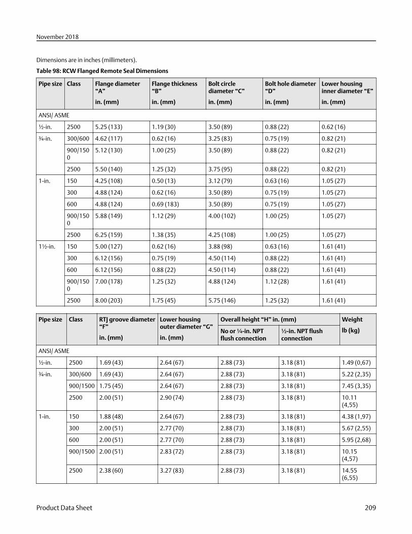
Dimensions are in inches (millimeters).
Table 98: RCW Flanged Remote Seal Dimensions
Pipe size Class Flange diameter“A”
in. (mm)
Flange thickness“B”
in. (mm)
Bolt circlediameter “C”
in. (mm)
Bolt hole diameter“D”
in. (mm)
Lower housinginner diameter “E”
in. (mm)
ANSI/ ASME
½-in. 2500 5.25 (133) 1.19 (30) 3.50 (89) 0.88 (22) 0.62 (16)
¾-in.
300/600 4.62 (117) 0.62 (16) 3.25 (83) 0.75 (19) 0.82 (21)
900/1500
5.12 (130) 1.00 (25) 3.50 (89) 0.88 (22) 0.82 (21)
2500 5.50 (140) 1.25 (32) 3.75 (95) 0.88 (22) 0.82 (21)
1-in.
150 4.25 (108) 0.50 (13) 3.12 (79) 0.63 (16) 1.05 (27)
300 4.88 (124) 0.62 (16) 3.50 (89) 0.75 (19) 1.05 (27)
600 4.88 (124) 0.69 (183) 3.50 (89) 0.75 (19) 1.05 (27)
900/1500
5.88 (149) 1.12 (29) 4.00 (102) 1.00 (25) 1.05 (27)
2500 6.25 (159) 1.38 (35) 4.25 (108) 1.00 (25) 1.05 (27)
1½-in. 150 5.00 (127) 0.62 (16) 3.88 (98) 0.63 (16) 1.61 (41)
300 6.12 (156) 0.75 (19) 4.50 (114) 0.88 (22) 1.61 (41)
600 6.12 (156) 0.88 (22) 4.50 (114) 0.88 (22) 1.61 (41)
900/1500
7.00 (178) 1.25 (32) 4.88 (124) 1.12 (28) 1.61 (41)
2500 8.00 (203) 1.75 (45) 5.75 (146) 1.25 (32) 1.61 (41)
Pipe size Class RTJ groove diameter“F”
in. (mm)
Lower housingouter diameter “G”
in. (mm)
Overall height “H” in. (mm) Weight
lb (kg)No or ¼-in. NPTflush connection
½-in. NPT flushconnection
ANSI/ ASME
½-in. 2500 1.69 (43) 2.64 (67) 2.88 (73) 3.18 (81) 1.49 (0,67)
¾-in.
300/600 1.69 (43) 2.64 (67) 2.88 (73) 3.18 (81) 5.22 (2,35)
900/1500 1.75 (45) 2.64 (67) 2.88 (73) 3.18 (81) 7.45 (3,35)
2500 2.00 (51) 2.90 (74) 2.88 (73) 3.18 (81) 10.11(4,55)
1-in.
150 1.88 (48) 2.64 (67) 2.88 (73) 3.18 (81) 4.38 (1,97)
300 2.00 (51) 2.77 (70) 2.88 (73) 3.18 (81) 5.67 (2,55)
600 2.00 (51) 2.77 (70) 2.88 (73) 3.18 (81) 5.95 (2,68)
900/1500 2.00 (51) 2.83 (72) 2.88 (73) 3.18 (81) 10.15(4,57)
2500 2.38 (60) 3.27 (83) 2.88 (73) 3.18 (81) 14.55(6,55)
November 2018
Product Data Sheet 209
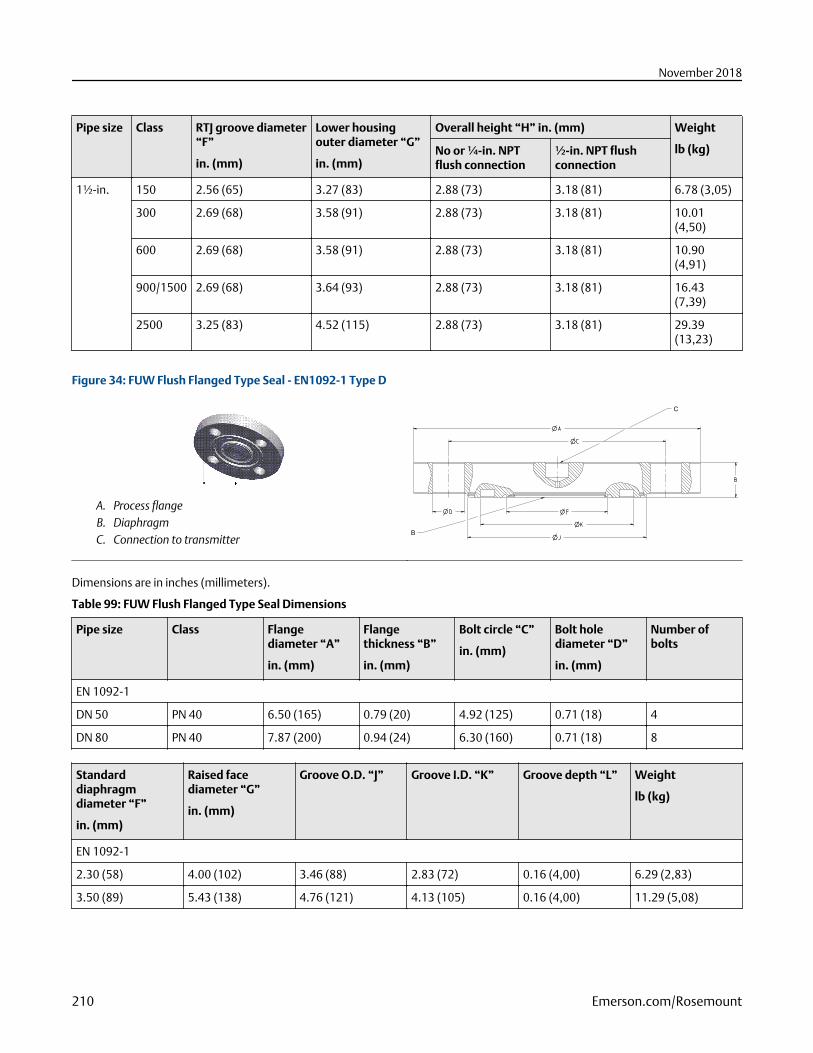
Pipe size Class RTJ groove diameter“F”
in. (mm)
Lower housingouter diameter “G”
in. (mm)
Overall height “H” in. (mm) Weight
lb (kg)No or ¼-in. NPTflush connection
½-in. NPT flushconnection
1½-in. 150 2.56 (65) 3.27 (83) 2.88 (73) 3.18 (81) 6.78 (3,05)
300 2.69 (68) 3.58 (91) 2.88 (73) 3.18 (81) 10.01(4,50)
600 2.69 (68) 3.58 (91) 2.88 (73) 3.18 (81) 10.90(4,91)
900/1500 2.69 (68) 3.64 (93) 2.88 (73) 3.18 (81) 16.43(7,39)
2500 3.25 (83) 4.52 (115) 2.88 (73) 3.18 (81) 29.39(13,23)
Figure 34: FUW Flush Flanged Type Seal - EN1092-1 Type D
A. Process flangeB. DiaphragmC. Connection to transmitter
C
B
Dimensions are in inches (millimeters).
Table 99: FUW Flush Flanged Type Seal Dimensions
Pipe size Class Flangediameter “A”
in. (mm)
Flangethickness “B”
in. (mm)
Bolt circle “C”
in. (mm)
Bolt holediameter “D”
in. (mm)
Number ofbolts
EN 1092-1
DN 50 PN 40 6.50 (165) 0.79 (20) 4.92 (125) 0.71 (18) 4
DN 80 PN 40 7.87 (200) 0.94 (24) 6.30 (160) 0.71 (18) 8
Standarddiaphragmdiameter “F”
in. (mm)
Raised facediameter “G”
in. (mm)
Groove O.D. “J” Groove I.D. “K” Groove depth “L” Weight
lb (kg)
EN 1092-1
2.30 (58) 4.00 (102) 3.46 (88) 2.83 (72) 0.16 (4,00) 6.29 (2,83)
3.50 (89) 5.43 (138) 4.76 (121) 4.13 (105) 0.16 (4,00) 11.29 (5,08)
November 2018
210 Emerson.com/Rosemount
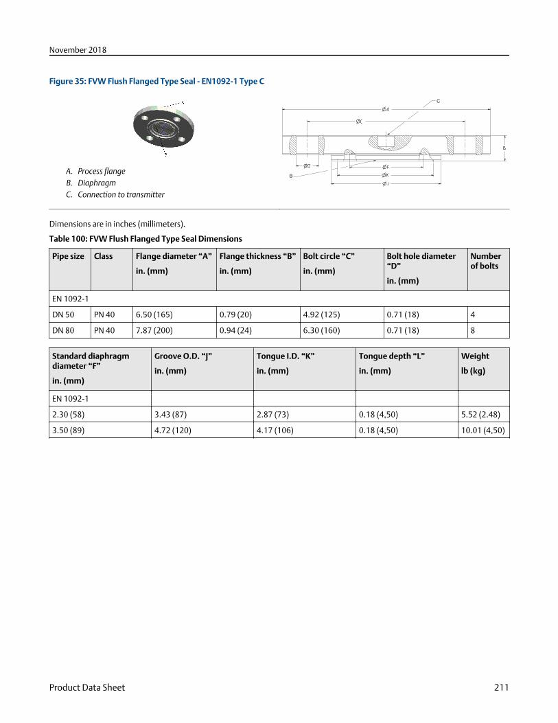
Figure 35: FVW Flush Flanged Type Seal - EN1092-1 Type C
A. Process flangeB. DiaphragmC. Connection to transmitter
C
B
Dimensions are in inches (millimeters).
Table 100: FVW Flush Flanged Type Seal Dimensions
Pipe size Class Flange diameter “A”
in. (mm)
Flange thickness “B”
in. (mm)
Bolt circle “C”
in. (mm)
Bolt hole diameter“D”
in. (mm)
Numberof bolts
EN 1092-1
DN 50 PN 40 6.50 (165) 0.79 (20) 4.92 (125) 0.71 (18) 4
DN 80 PN 40 7.87 (200) 0.94 (24) 6.30 (160) 0.71 (18) 8
Standard diaphragmdiameter “F”
in. (mm)
Groove O.D. “J”
in. (mm)
Tongue I.D. “K”
in. (mm)
Tongue depth “L”
in. (mm)
Weight
lb (kg)
EN 1092-1
2.30 (58) 3.43 (87) 2.87 (73) 0.18 (4,50) 5.52 (2.48)
3.50 (89) 4.72 (120) 4.17 (106) 0.18 (4,50) 10.01 (4,50)
November 2018
Product Data Sheet 211
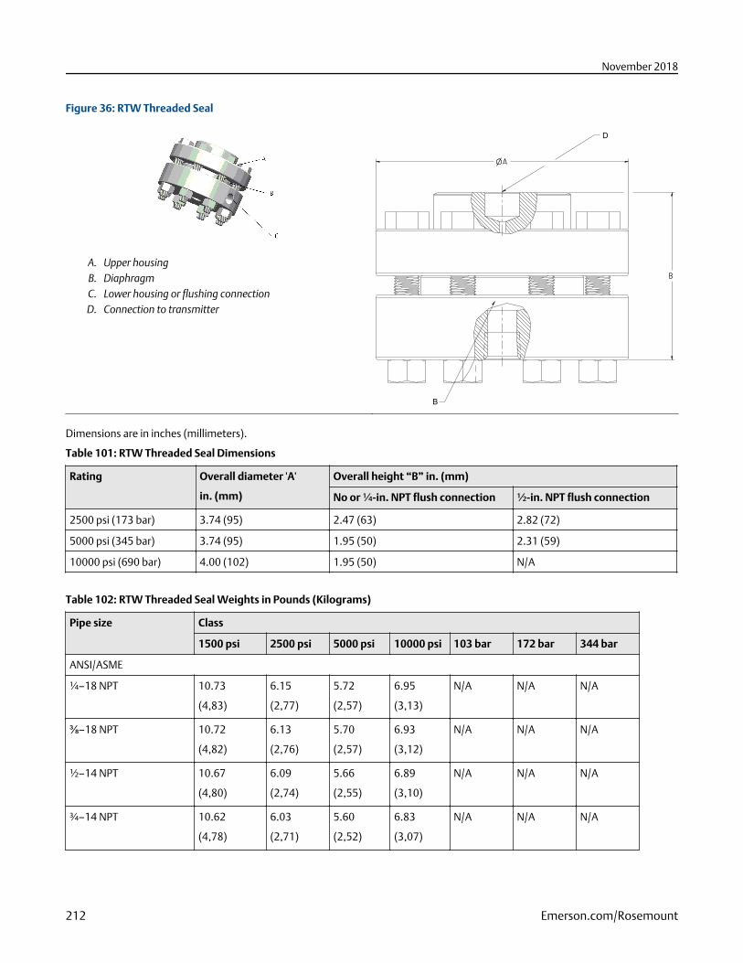
Figure 36: RTW Threaded Seal
A. Upper housingB. DiaphragmC. Lower housing or flushing connectionD. Connection to transmitter
D
B
Dimensions are in inches (millimeters).
Table 101: RTW Threaded Seal Dimensions
Rating Overall diameter 'A'
in. (mm)
Overall height “B” in. (mm)
No or ¼-in. NPT flush connection ½-in. NPT flush connection
2500 psi (173 bar) 3.74 (95) 2.47 (63) 2.82 (72)
5000 psi (345 bar) 3.74 (95) 1.95 (50) 2.31 (59)
10000 psi (690 bar) 4.00 (102) 1.95 (50) N/A
Table 102: RTW Threaded Seal Weights in Pounds (Kilograms)
Pipe size Class
1500 psi 2500 psi 5000 psi 10000 psi 103 bar 172 bar 344 bar
ANSI/ASME
¼–18 NPT 10.73
(4,83)
6.15
(2,77)
5.72
(2,57)
6.95
(3,13)
N/A N/A N/A
⅜–18 NPT 10.72
(4,82)
6.13
(2,76)
5.70
(2,57)
6.93
(3,12)
N/A N/A N/A
½–14 NPT 10.67
(4,80)
6.09
(2,74)
5.66
(2,55)
6.89
(3,10)
N/A N/A N/A
¾–14 NPT 10.62
(4,78)
6.03
(2,71)
5.60
(2,52)
6.83
(3,07)
N/A N/A N/A
November 2018
212 Emerson.com/Rosemount
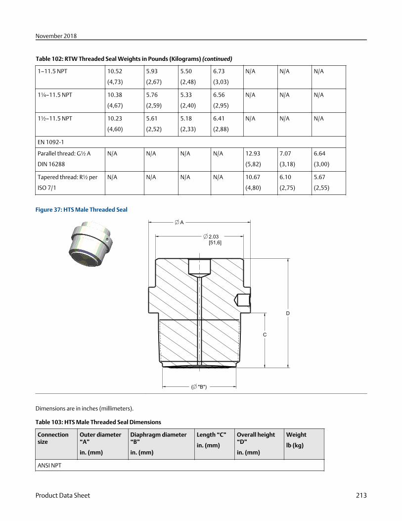
Table 102: RTW Threaded Seal Weights in Pounds (Kilograms) (continued)
1–11.5 NPT 10.52
(4,73)
5.93
(2,67)
5.50
(2,48)
6.73
(3,03)
N/A N/A N/A
1¼–11.5 NPT 10.38
(4,67)
5.76
(2,59)
5.33
(2,40)
6.56
(2,95)
N/A N/A N/A
1½–11.5 NPT 10.23
(4,60)
5.61
(2,52)
5.18
(2,33)
6.41
(2,88)
N/A N/A N/A
EN 1092-1
Parallel thread: G½ A
DIN 16288
N/A N/A N/A N/A 12.93
(5,82)
7.07
(3,18)
6.64
(3,00)
Tapered thread: R½ per
ISO 7/1
N/A N/A N/A N/A 10.67
(4,80)
6.10
(2,75)
5.67
(2,55)
Figure 37: HTS Male Threaded Seal
( "B")
D
C
A
2.03[51,6]
Dimensions are in inches (millimeters).
Table 103: HTS Male Threaded Seal Dimensions
Connectionsize
Outer diameter“A”
in. (mm)
Diaphragm diameter“B”
in. (mm)
Length “C”
in. (mm)
Overall height“D”
in. (mm)
Weight
lb (kg)
ANSI NPT
November 2018
Product Data Sheet 213
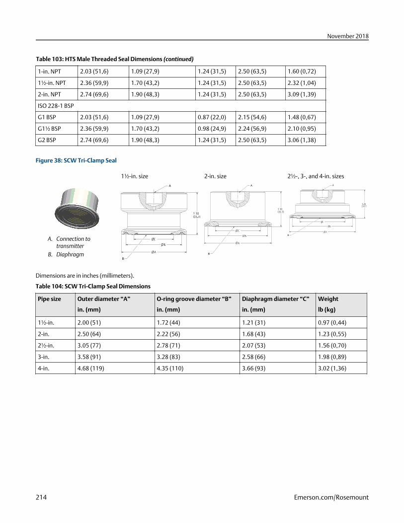
Table 103: HTS Male Threaded Seal Dimensions (continued)
1-in. NPT 2.03 (51,6) 1.09 (27,9) 1.24 (31,5) 2.50 (63,5) 1.60 (0,72)
1½-in. NPT 2.36 (59,9) 1.70 (43,2) 1.24 (31,5) 2.50 (63,5) 2.32 (1,04)
2-in. NPT 2.74 (69,6) 1.90 (48,3) 1.24 (31,5) 2.50 (63,5) 3.09 (1,39)
ISO 228-1 BSP
G1 BSP 2.03 (51,6) 1.09 (27,9) 0.87 (22,0) 2.15 (54,6) 1.48 (0,67)
G1½ BSP 2.36 (59,9) 1.70 (43,2) 0.98 (24,9) 2.24 (56,9) 2.10 (0,95)
G2 BSP 2.74 (69,6) 1.90 (48,3) 1.24 (31,5) 2.50 (63,5) 3.06 (1,38)
Figure 38: SCW Tri-Clamp Seal
1½-in. size 2-in. size 2½-, 3-, and 4-in. sizes
A. Connection totransmitter
B. Diaphragm
A
B
A
B
A
B
Dimensions are in inches (millimeters).
Table 104: SCW Tri-Clamp Seal Dimensions
Pipe size Outer diameter “A”
in. (mm)
O-ring groove diameter “B”
in. (mm)
Diaphragm diameter “C”
in. (mm)
Weight
lb (kg)
1½-in. 2.00 (51) 1.72 (44) 1.21 (31) 0.97 (0,44)
2-in. 2.50 (64) 2.22 (56) 1.68 (43) 1.23 (0,55)
2½-in. 3.05 (77) 2.78 (71) 2.07 (53) 1.56 (0,70)
3-in. 3.58 (91) 3.28 (83) 2.58 (66) 1.98 (0,89)
4-in. 4.68 (119) 4.35 (110) 3.66 (93) 3.02 (1,36)
November 2018
214 Emerson.com/Rosemount
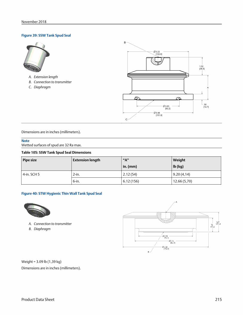
Figure 39: SSW Tank Spud Seal
A. Extension lengthB. Connection to transmitterC. Diaphragm
3.63[92,2]
1.52[38,5]
5.98[151,9]
.50[12,7]
5.22[132,6]
A
B
C
Dimensions are in inches (millimeters).
NoteWetted surfaces of spud are 32 Ra max.
Table 105: SSW Tank Spud Seal Dimensions
Pipe size Extension length “A”
in. (mm)
Weight
lb (kg)
4-in. SCH 5 2-in. 2.12 (54) 9.20 (4,14)
6-in. 6.12 (156) 12.66 (5,70)
Figure 40: STW Hygienic Thin Wall Tank Spud Seal
A. Connection to transmitterB. Diaphragm
A
B
Weight = 3.09 lb (1,39 kg)
Dimensions are in inches (millimeters).
November 2018
Product Data Sheet 215
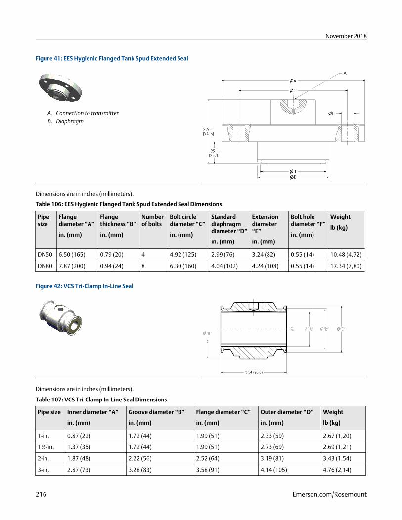
Figure 41: EES Hygienic Flanged Tank Spud Extended Seal
A. Connection to transmitterB. Diaphragm
A
Dimensions are in inches (millimeters).
Table 106: EES Hygienic Flanged Tank Spud Extended Seal Dimensions
Pipesize
Flangediameter “A”
in. (mm)
Flangethickness “B”
in. (mm)
Numberof bolts
Bolt circlediameter “C”
in. (mm)
Standarddiaphragmdiameter “D”
in. (mm)
Extensiondiameter“E”
in. (mm)
Bolt holediameter “F”
in. (mm)
Weight
lb (kg)
DN50 6.50 (165) 0.79 (20) 4 4.92 (125) 2.99 (76) 3.24 (82) 0.55 (14) 10.48 (4,72)
DN80 7.87 (200) 0.94 (24) 8 6.30 (160) 4.04 (102) 4.24 (108) 0.55 (14) 17.34 (7,80)
Figure 42: VCS Tri-Clamp In-Line Seal
3.54 (90,0)
Dimensions are in inches (millimeters).
Table 107: VCS Tri-Clamp In-Line Seal Dimensions
Pipe size Inner diameter “A”
in. (mm)
Groove diameter “B”
in. (mm)
Flange diameter “C”
in. (mm)
Outer diameter “D”
in. (mm)
Weight
lb (kg)
1-in. 0.87 (22) 1.72 (44) 1.99 (51) 2.33 (59) 2.67 (1,20)
1½-in. 1.37 (35) 1.72 (44) 1.99 (51) 2.73 (69) 2.69 (1,21)
2-in. 1.87 (48) 2.22 (56) 2.52 (64) 3.19 (81) 3.43 (1,54)
3-in. 2.87 (73) 3.28 (83) 3.58 (91) 4.14 (105) 4.76 (2,14)
November 2018
216 Emerson.com/Rosemount
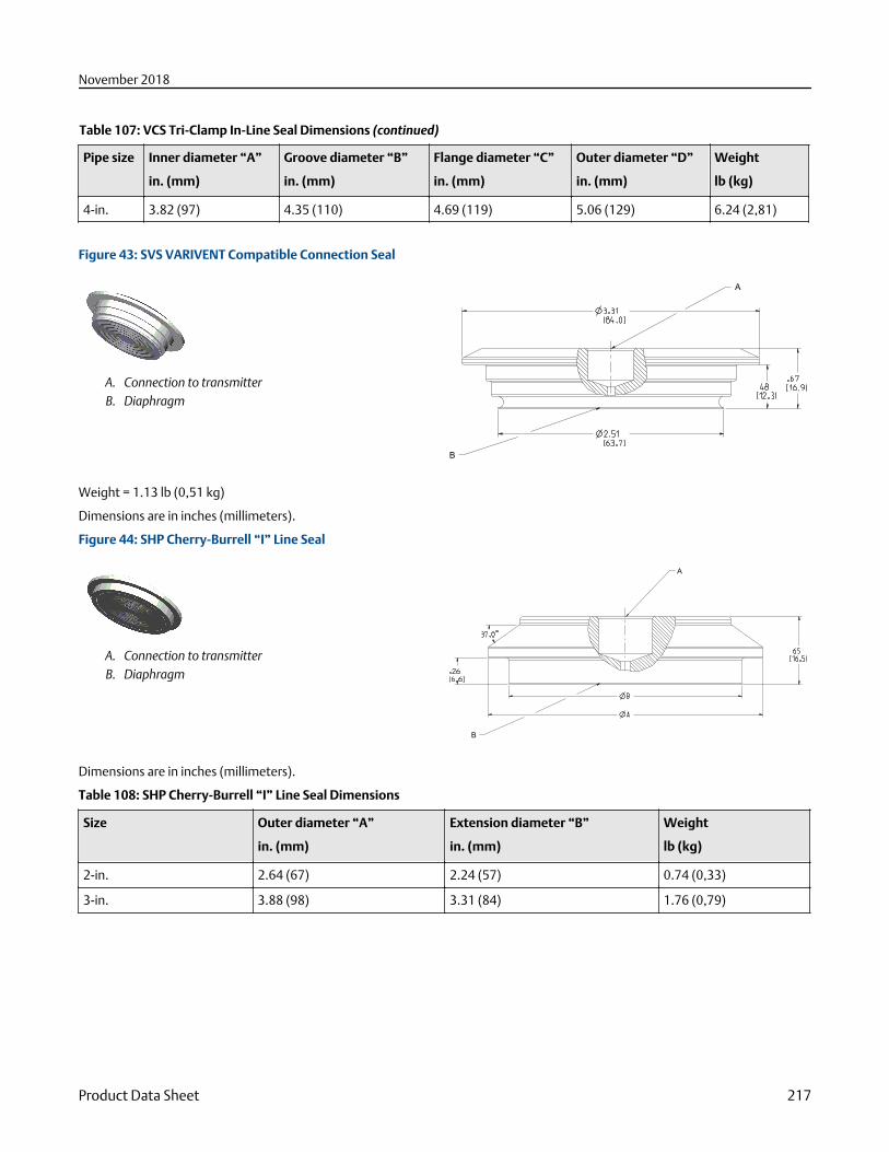
Table 107: VCS Tri-Clamp In-Line Seal Dimensions (continued)
Pipe size Inner diameter “A”
in. (mm)
Groove diameter “B”
in. (mm)
Flange diameter “C”
in. (mm)
Outer diameter “D”
in. (mm)
Weight
lb (kg)
4-in. 3.82 (97) 4.35 (110) 4.69 (119) 5.06 (129) 6.24 (2,81)
Figure 43: SVS VARIVENT Compatible Connection Seal
A. Connection to transmitterB. Diaphragm
A
B
Weight = 1.13 lb (0,51 kg)
Dimensions are in inches (millimeters).
Figure 44: SHP Cherry-Burrell “I” Line Seal
A. Connection to transmitterB. Diaphragm
A
B
Dimensions are in inches (millimeters).
Table 108: SHP Cherry-Burrell “I” Line Seal Dimensions
Size Outer diameter “A”
in. (mm)
Extension diameter “B”
in. (mm)
Weight
lb (kg)
2-in. 2.64 (67) 2.24 (57) 0.74 (0,33)
3-in. 3.88 (98) 3.31 (84) 1.76 (0,79)
November 2018
Product Data Sheet 217
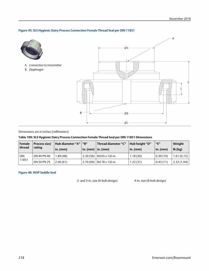
Figure 45: SLS Hygienic Dairy Process Connection Female Thread Seal per DIN 11851
A. Connection to transmitterB. Diaphragm
A
B
Dimensions are in inches (millimeters)
Table 109: SLS Hygienic Dairy Process Connection Female Thread Seal per DIN 11851 Dimensions
Femalethread
Process size/rating
Hub diameter “A”
in. (mm)
“B”
in. (mm)
Thread diameter “C”
in. (mm)
Hub height “D”
in. (mm)
“E”
in. (mm)
Weight
lb (kg)
DIN11851
DN 40 PN 40 1.89 (48) 2.20 (56) Rd 65 x 1/6-in. 1.18 (30) 0.39 (10) 1.61 (0,72)
DN 50 PN 25 2.40 (61) 2.70 (69) Rd 78 x 1/6-in. 1.22 (31) 0.43 (11) 2.32 (1,04)
Figure 46: WSP Saddle Seal
2- and 3-in. size (6-bolt design) 4-in. size (8-bolt design)
November 2018
218 Emerson.com/Rosemount
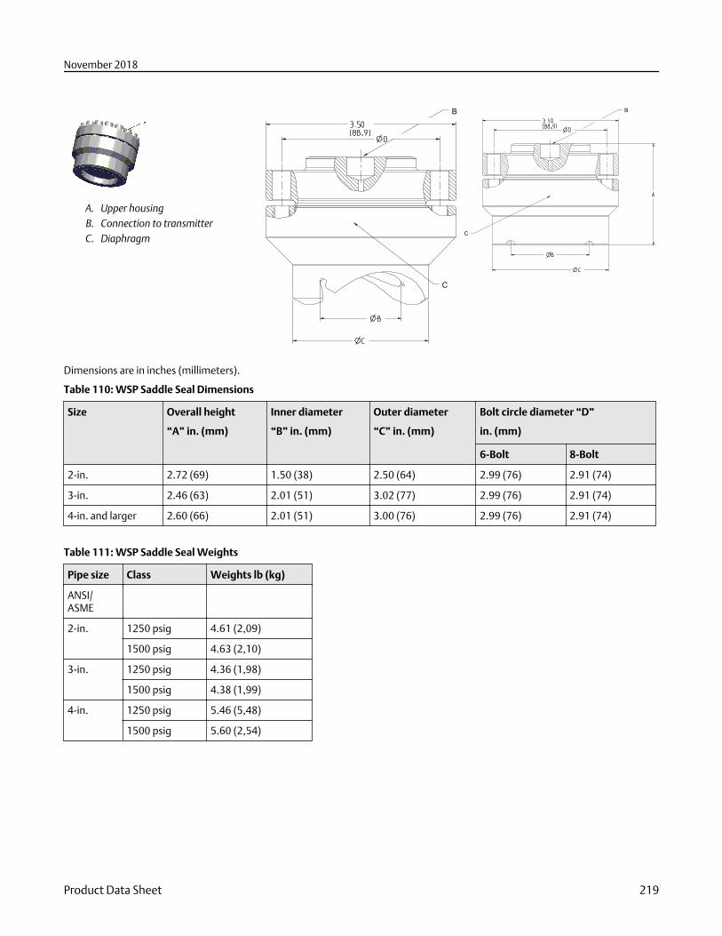
A. Upper housingB. Connection to transmitterC. Diaphragm
B
C
B
C
Dimensions are in inches (millimeters).
Table 110: WSP Saddle Seal Dimensions
Size Overall height
“A” in. (mm)
Inner diameter
“B” in. (mm)
Outer diameter
“C” in. (mm)
Bolt circle diameter “D”
in. (mm)
6-Bolt 8-Bolt
2-in. 2.72 (69) 1.50 (38) 2.50 (64) 2.99 (76) 2.91 (74)
3-in. 2.46 (63) 2.01 (51) 3.02 (77) 2.99 (76) 2.91 (74)
4-in. and larger 2.60 (66) 2.01 (51) 3.00 (76) 2.99 (76) 2.91 (74)
Table 111: WSP Saddle Seal Weights
Pipe size Class Weights lb (kg)
ANSI/ASME
2-in. 1250 psig 4.61 (2,09)
1500 psig 4.63 (2,10)
3-in. 1250 psig 4.36 (1,98)
1500 psig 4.38 (1,99)
4-in. 1250 psig 5.46 (5,48)
1500 psig 5.60 (2,54)
November 2018
Product Data Sheet 219
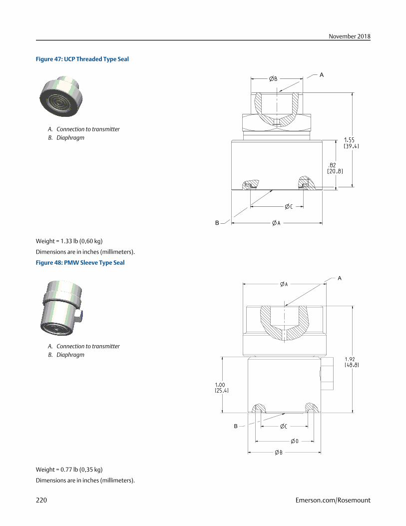
Figure 47: UCP Threaded Type Seal
A. Connection to transmitterB. Diaphragm
A
B
Weight = 1.33 lb (0,60 kg)
Dimensions are in inches (millimeters).
Figure 48: PMW Sleeve Type Seal
A. Connection to transmitterB. Diaphragm
A
B
Weight = 0.77 lb (0,35 kg)
Dimensions are in inches (millimeters).
November 2018
220 Emerson.com/Rosemount
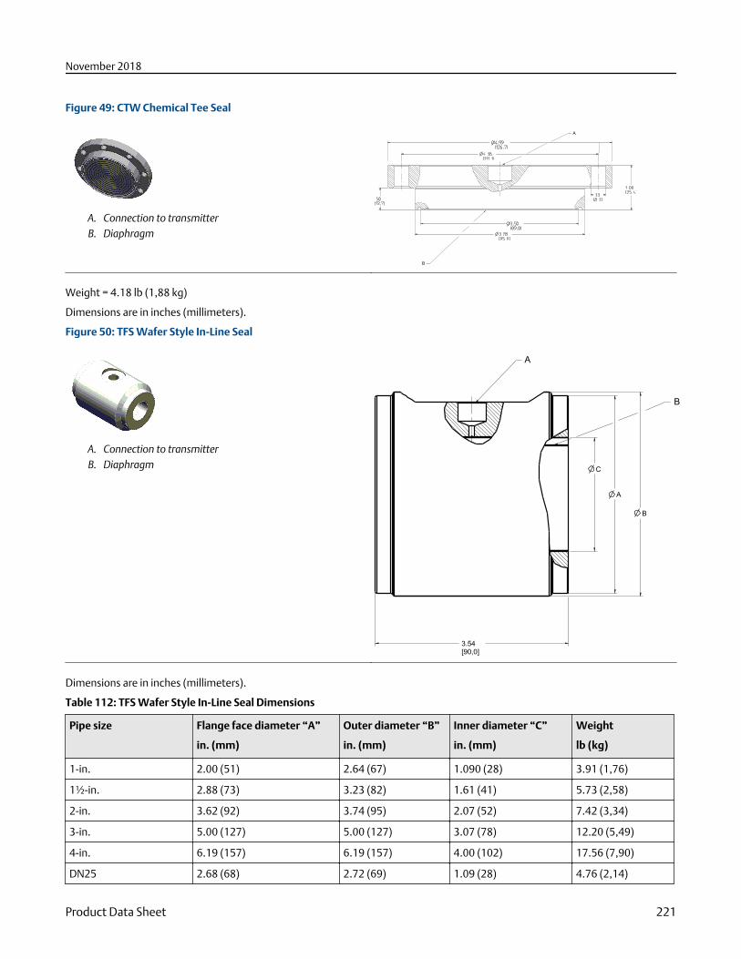
Figure 49: CTW Chemical Tee Seal
A. Connection to transmitterB. Diaphragm
B
A
Weight = 4.18 lb (1,88 kg)
Dimensions are in inches (millimeters).
Figure 50: TFS Wafer Style In-Line Seal
A. Connection to transmitterB. Diaphragm
B
A
C
3.54[90,0]
A
B
Dimensions are in inches (millimeters).
Table 112: TFS Wafer Style In-Line Seal Dimensions
Pipe size Flange face diameter “A”
in. (mm)
Outer diameter “B”
in. (mm)
Inner diameter “C”
in. (mm)
Weight
lb (kg)
1-in. 2.00 (51) 2.64 (67) 1.090 (28) 3.91 (1,76)
1½-in. 2.88 (73) 3.23 (82) 1.61 (41) 5.73 (2,58)
2-in. 3.62 (92) 3.74 (95) 2.07 (52) 7.42 (3,34)
3-in. 5.00 (127) 5.00 (127) 3.07 (78) 12.20 (5,49)
4-in. 6.19 (157) 6.19 (157) 4.00 (102) 17.56 (7,90)
DN25 2.68 (68) 2.72 (69) 1.09 (28) 4.76 (2,14)
November 2018
Product Data Sheet 221
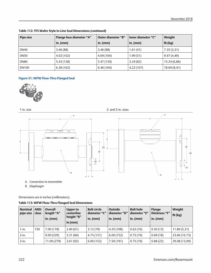
Table 112: TFS Wafer Style In-Line Seal Dimensions (continued)
Pipe size Flange face diameter “A”
in. (mm)
Outer diameter “B”
in. (mm)
Inner diameter “C”
in. (mm)
Weight
lb (kg)
DN40 3.46 (88) 3.46 (88) 1.61 (41) 7.35 (3,31)
DN50 4.02 (102) 4.09 (104) 1.99 (51) 9.97 (4,49)
DN80 5.43 (138) 5.47 (139) 3.24 (82) 15.24 (6,86)
DN100 6.38 (162) 6.46 (164) 4.22 (107) 18.69 (8,41)
Figure 51: WFW Flow-Thru Flanged Seal
1-in. size 2- and 3-in. sizes
A
B
A. Connection to transmitterB. Diaphragm
A
B
Dimensions are in inches (millimeters).
Table 113: WFW Flow-Thru Flanged Seal Dimensions
Nominalpipe size
ANSIclass
Overalllength “A”
in. (mm)
Upper tocenterlineheight “B”
in (mm)
Bolt circlediameter “C”
in. (mm)
Outsidediameter “D”
in. (mm)
Bolt holediameter “E”
in. (mm)
Flangethickness “F”
in. (mm)
Weight
lb (kg)
1-in. 150 7.00 (178) 2.40 (61) 3.12 (79) 4.25 (108) 0.62 (16) 0.50 (13) 11.80 (5,31)
2-in. 9.00 (229) 3.31 (84) 4.75 (121) 6.00 (152) 0.75 (19) 0.69 (18) 23.66 (10,73)
3-in. 11.00 (279) 3.61 (92) 6.00 (152) 7.50 (191) 0.75 (19) 0.88 (22) 29.08 (13,09)
November 2018
222 Emerson.com/Rosemount
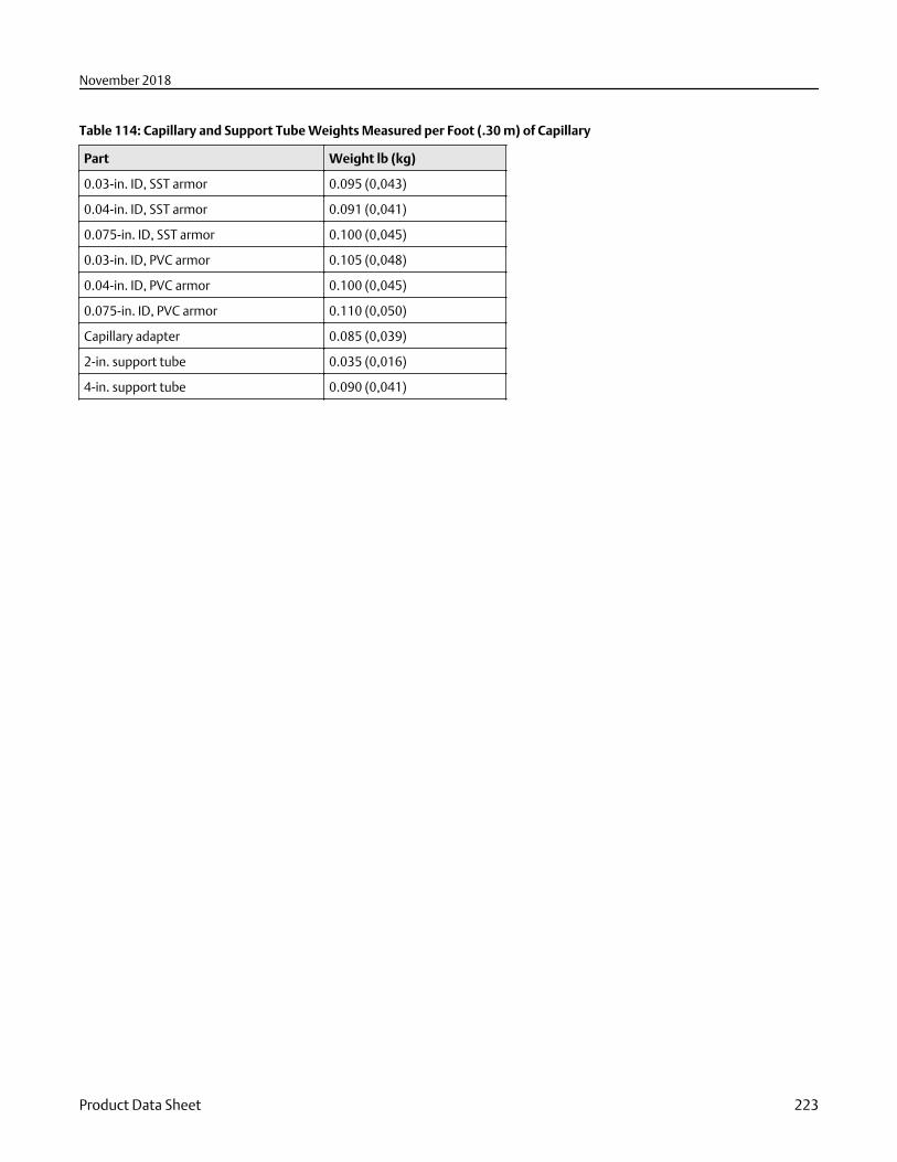
Table 114: Capillary and Support Tube Weights Measured per Foot (.30 m) of Capillary
Part Weight lb (kg)
0.03-in. ID, SST armor 0.095 (0,043)
0.04-in. ID, SST armor 0.091 (0,041)
0.075-in. ID, SST armor 0.100 (0,045)
0.03-in. ID, PVC armor 0.105 (0,048)
0.04-in. ID, PVC armor 0.100 (0,045)
0.075-in. ID, PVC armor 0.110 (0,050)
Capillary adapter 0.085 (0,039)
2-in. support tube 0.035 (0,016)
4-in. support tube 0.090 (0,041)
November 2018
Product Data Sheet 223
00813-0100-4016Rev. RG
November 2018
Global HeadquartersEmerson Automation Solutions6021 Innovation Blvd.Shakopee, MN 55379, USA
+1 800 999 9307 or +1 952 906 8888
+1 952 949 7001
North America Regional OfficeEmerson Automation Solutions8200 Market Blvd.Chanhassen, MN 55317, USA
+1 800 999 9307 or +1 952 906 8888
+1 952 949 7001
Latin America Regional OfficeEmerson Automation Solutions1300 Concord Terrace, Suite 400Sunrise, FL 33323, USA
+1 954 846 5030
+1 954 846 5121
Europe Regional OfficeEmerson Automation Solutions EuropeGmbHNeuhofstrasse 19a P.O. Box 1046CH 6340 BaarSwitzerland
+41 (0) 41 768 6111
+41 (0) 41 768 6300
Asia Pacific Regional OfficeEmerson Automation Solutions1 Pandan CrescentSingapore 128461
+65 6777 8211
+65 6777 0947
Middle East and Africa Regional OfficeEmerson Automation SolutionsEmerson FZE P.O. Box 17033Jebel Ali Free Zone - South 2Dubai, United Arab Emirates
+971 4 8118100
+971 4 8865465
Linkedin.com/company/Emerson-Automation-Solutions
Twitter.com/Rosemount_News
Facebook.com/Rosemount
Youtube.com/user/RosemountMeasurement
Google.com/+RosemountMeasurement
©2018 Emerson. All rights reserved.
Emerson Terms and Conditions of Sale are available upon request. The Emerson logo is atrademark and service mark of Emerson Electric Co. Rosemount is mark of one of theEmerson family of companies. All other marks are the property of their respective owners.
Recommended