PRODUCTION
TECHNOLOGY MATERIAL
2015
MATERIAL BY KUNALSINH KATHIA M.E MACHINE DESIGN (HJDITER)
HJD INSTITUTE OF TECHNICAL EDUCATION & RESERACH | KERA

Cutting Fluids & Tool Wear.pdf
Cutting tool failure.pdf
Cutting tool geometry.pdf
Cutting tool materials.pdf
Mechanics of Chip Removal.pdf
Jigs & Fixtures clamping devices.pdf
Jigs and fixtures Locators.pdf
Drill Bushes & Jigs.pdf
Punch & Die.pdf
AJM.pdf
USM.pdf
ECM.pdf
EDM.pdf
GTU PAPER 1.pdf
GTU PAPER 2.pdf
GTU PAPER 3.pdf
GTU PAPER 4.pdf
Cutting Fluids & Tool
WearProf. Kunalsinh R. Kathia
Mechanical Engineering Department
HJD INSTITUTE
Prof. Kunalsinh Kathia (HJDITER)
Basic methods of controlling cutting
temperature
It is already realized that the cutting temperature, particularly when it is
quite high, is very detrimental for both cutting tools and the machined jobs
and hence need to be controlled, i.e., reduced as far as possible without
sacrificing productivity and product quality.
The methods generally employed for controlling machining temperature and
its detrimental effects are :
Proper selection of cutting tools; material and geometry .
Proper selection of cutting velocity and feed .
Proper selection and application of cutting fluid .
Prof. Kunalsinh Kathia (HJDITER)
Selection of material and geometry of cutting tool
for reducing cutting temperature and its effects
Cutting tool material may play significant role on reduction of cutting
temperature depending upon the work material.
PVD or CVD coating of HSS and carbide tools enables reduce cutting
temperature by reducing friction at the chip-tool and work-tool interfaces.
In high speed machining of steels lesser heat and cutting temperature develop
if machined by CBN tools which produce lesser cutting forces by retaining its
sharp geometry for its extreme hardness and high chemical stability.
The cutting tool temperature of ceramic tools decrease further if the thermal
conductivity of such tools is enhanced (by adding thermally conductive
materials like metals, carbides, etc in Al2O3)
Prof. Kunalsinh Kathia (HJDITER)
Selection of material and geometry of cutting tool
for reducing cutting temperature and its effects
Cutting temperature can be sizably controlled also by proper selection of the toolgeometry in the following ways.
large positive tool–rake helps in reducing heat and temperature
generation by reducing the cutting forces, but too much increase in rakemechanically and thermally weakens the cutting edges.
compound r10:40:03 AMake, preferably with chip–breaker, also enables reduceheat and temperature through reduction in cutting forces and friction
even for same amount of heat generation, the cutting temperature decreases withthe decrease in the principal cutting edge angle, φ as
nose radiusing of single point tools not only improves surface finish but also helpsin reducing cutting temperature to some extent.
Prof. Kunalsinh Kathia (HJDITER)
Selection of material and geometry of cutting tool
for reducing cutting temperature and its effects
Selection of cutting velocity and feed:
Cutting temperature can also be controlled to some extent, even withoutsacrificing MRR, by proper or optimum selection of the cutting velocity and feedwithin their feasible ranges.
The rate of heat generation and hence cutting temperature are governed by theamount of cutting power consumption, Pc where;
So apparently, increase in both so and Vc raise heat generation proportionately.
But increase in VC, though further enhances heat generation by faster rubbingaction, substantially reduces cutting forces, hence heat generation by reducing τsand also the form factor f. The overall relative effects of variation of Vc and sooncutting temperature will depend upon other machining conditions. Hence,depending upon the situation, the cutting temperature can be controlledsignificantly by optimum combination of Vc and so for a given MRR.
Prof. Kunalsinh Kathia (HJDITER)
Selection of material and geometry of cutting tool
for reducing cutting temperature and its effects
Control of cutting temperature by
application of cutting fluid:
Cutting fluid, if employed, reduces cutting
temperature directly by taking away the
heat from the cutting zone and also
indirectly by reducing generation of heat by
reducing cutting forces .
Prof. Kunalsinh Kathia (HJDITER)
Purposes of application of cutting fluid
in machining and grinding.
The basic purposes of cutting fluid application are :
• Cooling of the job and the tool to reduce the detrimental effects of cuttingtemperature on the job and the tool
• Lubrication at the chip–tool interface and the tool flanks to reduce cutting forcesand friction and thus the amount of heat generation.
• Cleaning the machining zone by washing away the chip – particles and debriswhich, if present, spoils the finished surface and accelerates damage of the cuttingedges
• Protection of the nascent finished surface – a thin layer of the cutting fluid sticksto the machined surface and thus prevents its harmful contamination by the gaseslike SO2, O2, H2S, NxOy present in the atmosphere.
However, the main aim of application of cutting fluid is to improve machinabilitythrough reduction of cutting forces and temperature, improvement by surfaceintegrity and enhancement of tool life.Prof. Kunalsinh Kathia (HJDITER)
Essential properties of cutting fluids To enable the cutting fluid fulfil its functional requirements without harming the
Machine – Fixture – Tool – Work (M-F-T-W) system and the operators, the cutting fluid should possess the following properties:
o For cooling :
• high specific heat, thermal conductivity and film coefficient for heat transfer
• spreading and wetting ability
o For lubrication :
• high lubricity without gumming and foaming
• wetting and spreading
• high film boiling point
• friction reduction at extreme pressure (EP) and temperature
o Chemical stability, non-corrosive to the materials of the M-F-T-W system
o less volatile and high flash point
o high resistance to bacterial growth
o odorless and also preferably colorless
o non toxic in both liquid and gaseous stage
o easily available and low cost. Prof. Kunalsinh Kathia (HJDITER)
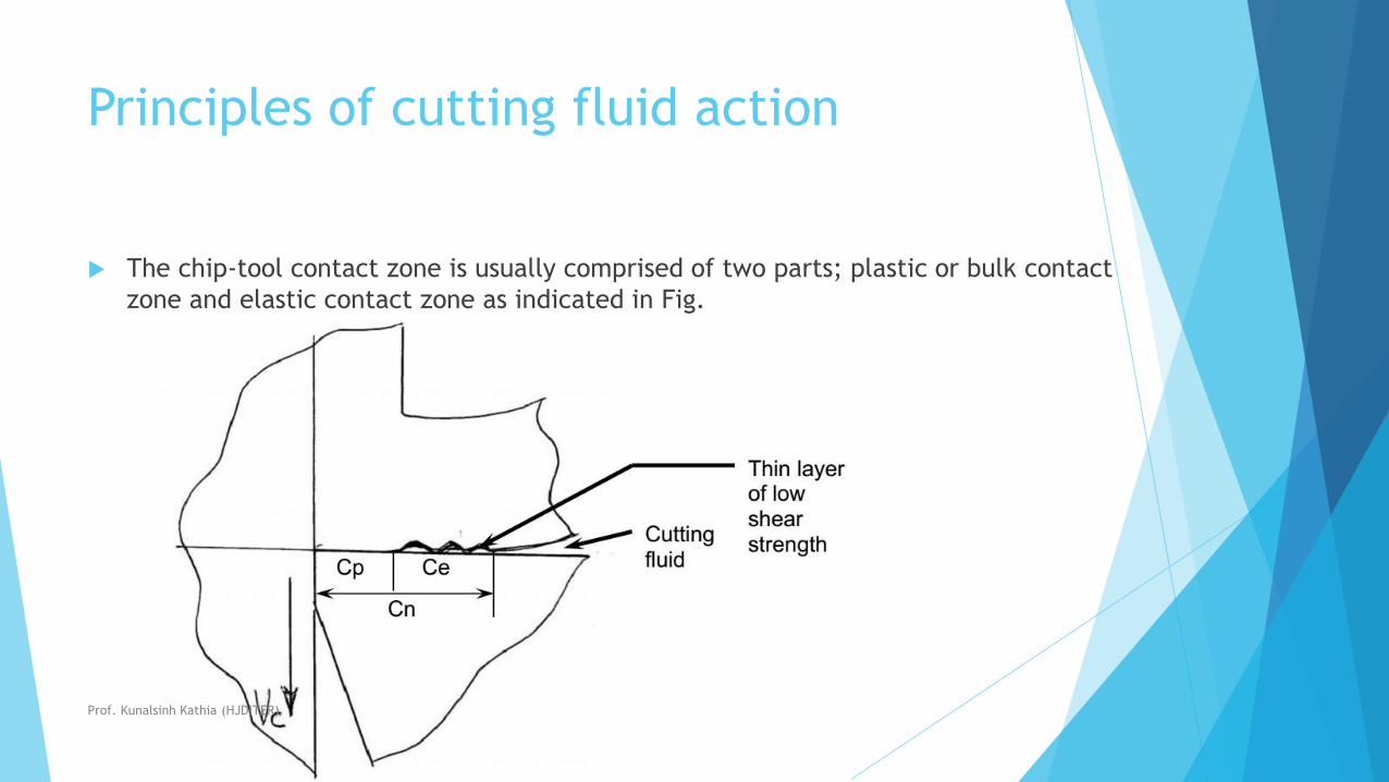
Principles of cutting fluid action
The chip-tool contact zone is usually comprised of two parts; plastic or bulk contact
zone and elastic contact zone as indicated in Fig.
Prof. Kunalsinh Kathia (HJDITER)
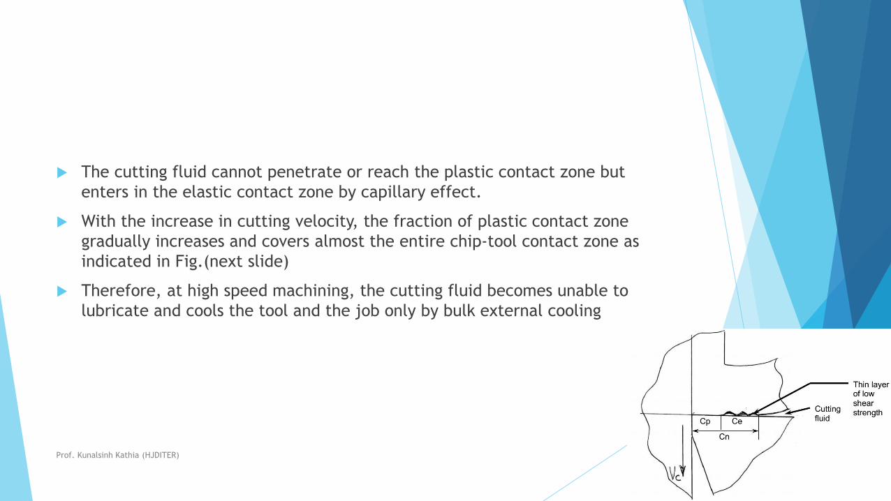
The cutting fluid cannot penetrate or reach the plastic contact zone but
enters in the elastic contact zone by capillary effect.
With the increase in cutting velocity, the fraction of plastic contact zone
gradually increases and covers almost the entire chip-tool contact zone as
indicated in Fig.(next slide)
Therefore, at high speed machining, the cutting fluid becomes unable to
lubricate and cools the tool and the job only by bulk external cooling
Prof. Kunalsinh Kathia (HJDITER)
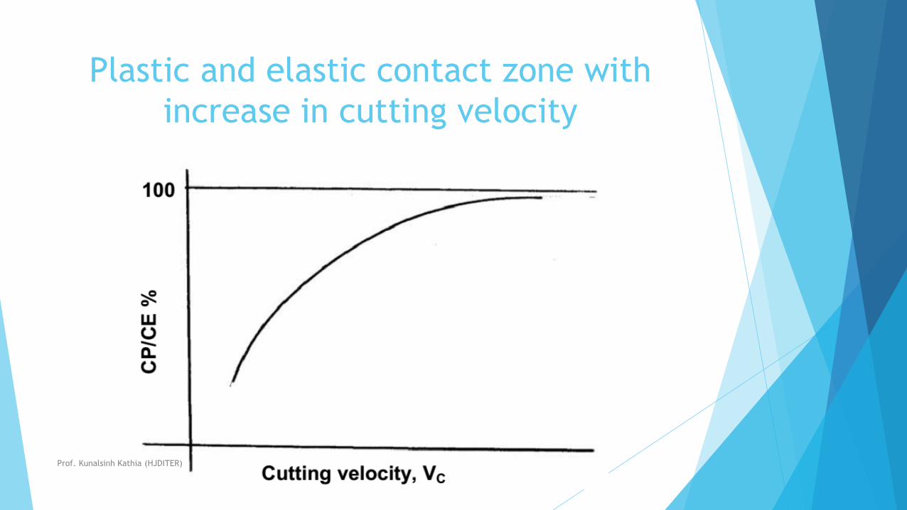
Plastic and elastic contact zone with
increase in cutting velocity
Prof. Kunalsinh Kathia (HJDITER)
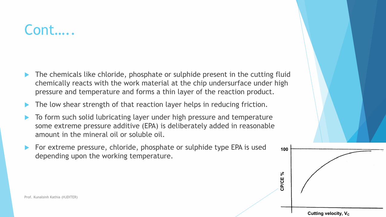
Cont…..
The chemicals like chloride, phosphate or sulphide present in the cutting fluid
chemically reacts with the work material at the chip undersurface under high
pressure and temperature and forms a thin layer of the reaction product.
The low shear strength of that reaction layer helps in reducing friction.
To form such solid lubricating layer under high pressure and temperature
some extreme pressure additive (EPA) is deliberately added in reasonable
amount in the mineral oil or soluble oil.
For extreme pressure, chloride, phosphate or sulphide type EPA is used
depending upon the working temperature.
Prof. Kunalsinh Kathia (HJDITER)

Types of cutting fluids and their
application
The cutting fluids, which are commonly used, are:
Air blast or compressed air only.
Water.
Soluble oil
Cutting oils
Chemical fluids
Solid or semi-solid lubricant
Cryogenic cutting fluid
Prof. Kunalsinh Kathia (HJDITER)
Air blast or compressed air only:
Machining of some materials like grey cast iron become inconvenient or
difficult if any cutting fluid is employed in liquid form.
In such case only air blast is recommended for cooling and cleaning .
Prof. Kunalsinh Kathia (HJDITER)
Water
For its good wetting and spreading properties and very
high specific heat.
water is considered as the best coolant and hence
employed where cooling is most urgent.
Prof. Kunalsinh Kathia (HJDITER)
Soluble oil
Water acts as the best coolant but does not lubricate.
Besides, use of only water may impair the machine-
fixture-tool-work system by rusting.
So oil containing some emulsifying agent and additive,
together called cutting compound, is mixed with water in
a suitable ratio ( 1 ~ 2 in 20 ~ 50).
This milk like white emulsion, called soluble oil, is very
common and widely used in machining and grinding.
Prof. Kunalsinh Kathia (HJDITER)
Cutting oils
Cutting oils are generally compounds of mineral
oil to which are added desired type and amount
of vegetable, animal or marine oils for improving
spreading, wetting and lubricating properties.
As and when required some EP additive is also
mixed to reduce friction and adhesion formation
in heavy cuts.
Prof. Kunalsinh Kathia (HJDITER)
Chemical fluids
These are occasionally used fluids which are water based
where some organic and or inorganic materials are
dissolved in water to enable desired cutting fluid action.
There are two types of such cutting fluid;
Chemically inactive type – high cooling, anti-rusting
and wetting but less lubricating
Active (surface) type – moderate cooling and
lubricating.
Prof. Kunalsinh Kathia (HJDITER)
Solid or semi-solid lubricant
Paste, waxes, soaps, graphite, Moly-di-sulphide
(MoS2) may also often be used,
either applied directly to the work piece or as an
extra agent in the tool to reduce friction and thus
cutting forces, temperature and tool wear.
Prof. Kunalsinh Kathia (HJDITER)

Cryogenic cutting fluid
Extremely cold (cryogenic) fluids (often in the
form of gases) like liquid CO2 or N2 are used in
some special cases for effective cooling without
creating much environmental pollution and health
hazards.
Prof. Kunalsinh Kathia (HJDITER)
Methods of application of cutting fluid
The effectiveness and expense of cutting fluid application significantly
depend also on how it is applied in respect of flow rate and direction of
application.
In machining, depending upon the requirement and facilities available,
cutting fluids are generally employed in the following ways (flow).
Prof. Kunalsinh Kathia (HJDITER)
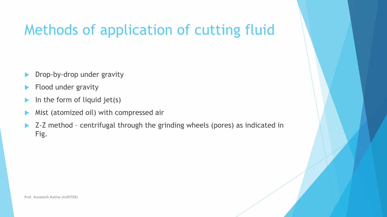
Methods of application of cutting fluid
Drop-by-drop under gravity
Flood under gravity
In the form of liquid jet(s)
Mist (atomized oil) with compressed air
Z-Z method – centrifugal through the grinding wheels (pores) as indicated in
Fig.
Prof. Kunalsinh Kathia (HJDITER)

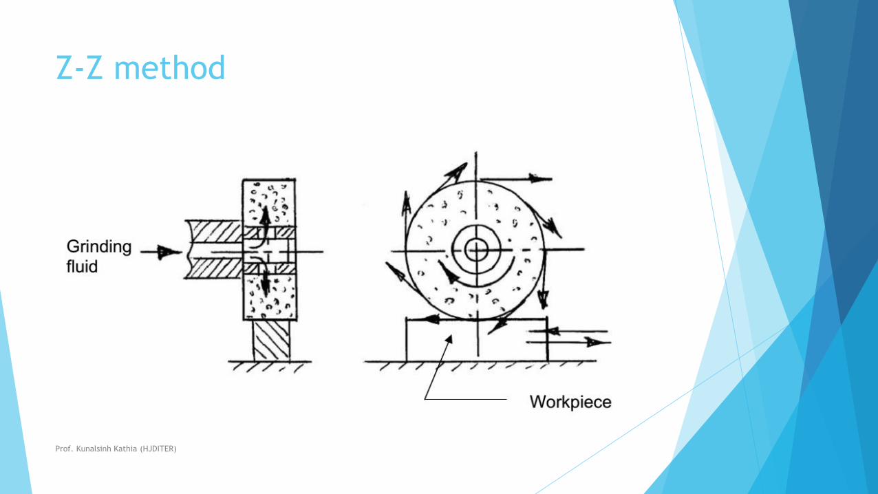
Z-Z method
The direction of application also significantly governs the effectiveness of the
cutting fluid in respect of reaching near the chip-tool and work-tool
interfaces.
Depending upon the requirement and accessibility the cutting fluid is applied
from top or side(s).
in operations like deep hole drilling the pressurized fluid is often sent
through the axial or inner spiral hole(s) of the drill.
For effective cooling and lubrication in high speed machining of ductile
metals having wide and plastic chip-tool contact, cutting fluid may be pushed
at high pressure to the chip-tool interface through hole(s) in the cutting tool.
Prof. Kunalsinh Kathia (HJDITER)
Z-Z method
Prof. Kunalsinh Kathia (HJDITER)
Cutting tool failure &
tool lifeProduction technology
Prof. kunalsinh kathia
Mechanical engineering department
Prof. Kunalsinh Kathia (HJDITER)
Failure of cutting tools
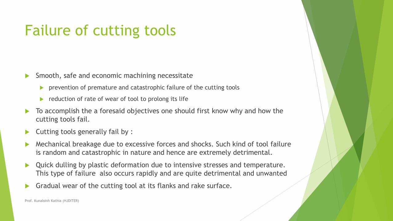
Smooth, safe and economic machining necessitate
prevention of premature and catastrophic failure of the cutting tools
reduction of rate of wear of tool to prolong its life
To accomplish the a foresaid objectives one should first know why and how the
cutting tools fail.
Cutting tools generally fail by :
Mechanical breakage due to excessive forces and shocks. Such kind of tool failure
is random and catastrophic in nature and hence are extremely detrimental.
Quick dulling by plastic deformation due to intensive stresses and temperature.
This type of failure also occurs rapidly and are quite detrimental and unwanted
Gradual wear of the cutting tool at its flanks and rake surface.
Prof. Kunalsinh Kathia (HJDITER)
The first two modes of tool failure are veryharmful not only for the tool but
also for the job and the machine tool. Hence these kinds of tool failure need
to be prevented by using suitable tool materials and geometry depending
upon the work material and cutting condition.
But failure by gradual wear, which is inevitable, cannot be prevented but can
be slowed down only to enhance the service life of the tool.
The cutting tool is withdrawn immediately after it fails or, if possible, just
before it totally fails.
For that one must understand that the tool has failed or is going to fail
shortly.
Prof. Kunalsinh Kathia (HJDITER)
Conditions
It is understood or considered that the tool has failed or about to fail by one or more of the following conditions :
(a) In R&D laboratories
• total breakage of the tool or tool tip(s)
• massive fracture at the cutting edge(s)
• excessive increase in cutting forces and/or vibration
• average wear (flank or crater) reaches its specified limit(s)
(b) In machining industries
• excessive (beyond limit) current or power consumption
• excessive vibration and/or abnormal sound (chatter)
• total breakage of the tool
• dimensional deviation beyond tolerance
• rapid worsening of surface finish
• adverse chip formation.
Prof. Kunalsinh Kathia (HJDITER)
Mechanisms and pattern (geometry) of
cutting tool wear
For the purpose of controlling tool wear one must understand the various mechanisms of wear, that the cutting tool undergoes under different conditions.
The common mechanisms of cutting tool wear are :
i) Mechanical wear
• thermally insensitive type; like abrasion, chipping and delamination
• thermally sensitive type; like adhesion, fracturing, flaking etc.
ii) Thermochemical wear
• macro-diffusion by mass dissolution
• micro-diffusion by atomic migration
iii) Chemical wear
iv) Galvanic wear
Prof. Kunalsinh Kathia (HJDITER)
In diffusion wear the material from the tool at its rubbing surfaces,
particularly at the rake surface gradually diffuses into the flowing chips either
in bulk or atom by atom when the tool material has chemical affinity or solid
solubility towards the work material.
The rate of such tool wear increases with the increase in temperature at the
cutting zone.
Diffusion wear becomes predominant when the cutting temperature becomes
very high due to high cutting velocity and high strength of the work material.
Chemical wear, leading to damages like grooving wear may occur if the tool
material is not enough chemically stable against the work material and/or the
atmospheric gases.
Prof. Kunalsinh Kathia (HJDITER)
Galvanic wear, based on electrochemical dissolution, seldom occurs when
both the work tool materials are electrically conductive, cutting zone
temperature is high and the cutting fluid acts as an electrolyte.
Prof. Kunalsinh Kathia (HJDITER)

Photographic view of the wear pattern
of a turning tool insert
Prof. Kunalsinh Kathia (HJDITER)
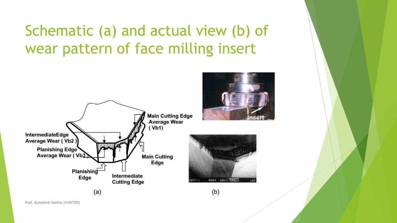
Schematic (a) and actual view (b) of
wear pattern of face milling insert
Prof. Kunalsinh Kathia (HJDITER)
In addition to ultimate failure of the tool, the following effects are also
caused by the growing tool-wear :
• increase in cutting forces and power consumption mainly due to the
principal flank wear
• increase in dimensional deviation and surface roughness mainly due to wear
of the tool-tips and auxiliary flank wear (Vs)
• odd sound and vibration
• worsening surface integrity
• mechanically weakening of the tool tip.
Prof. Kunalsinh Kathia (HJDITER)
Tool Life
Tool life generally indicates, the amount of satisfactory performance or service
rendered by a fresh tool or a cutting point till it is declared failed.
Tool life is defined in two ways :
(a) In R & D : Actual machining time (period) by which a fresh cutting tool (or
point) satisfactorily works after which it needs replacement or reconditioning. The
modern tools hardly fail prematurely or abruptly by mechanical breakage or rapid
plastic deformation. Those fail mostly by wearing process which systematically
grows slowly with machining time. In that case, tool life means the span of actual
machining time by which a fresh tool can work before attaining the specified limit
of tool wear. Mostly tool life is decided by the machining time till flank wear.
(b) In industries or shop floor : The length of time of satisfactory service or
amount of acceptable output provided by a fresh tool prior to it is required to
replace or recondition.
Prof. Kunalsinh Kathia (HJDITER)
Assessment of tool life
For R & D purposes, tool life is always assessed or expressed by span of
machining time in minutes, whereas, in industries besides machining time in
minutes some other means are also used to assess tool life, depending upon
the situation, such as …..
• no. of pieces of work machined
• total volume of material removed
• total length of cut.
Prof. Kunalsinh Kathia (HJDITER)
Measurement of tool wear
i) by loss of tool material in volume orweight, in one life time – this method
is crude and is generally applicable for critical tools like grinding wheels.
ii) by grooving and indentation method – in this approximate method wear
depth is measured indirectly by the difference in length of the groove or the
indentation outside and inside the worn area
iii) using optical microscope fitted with micrometer – very common and
effective method
iv) using scanning electron microscope (SEM) – used generally, for detailed
study; both qualitative and quantitative .
Prof. Kunalsinh Kathia (HJDITER)
Taylor’s tool life equation.
Wear and hence tool life of any tool for any work material is governed mainly
by the level of the machining parameters i.e., cutting velocity, (VC), feed,
(so) and depth of cut (t).
Cutting velocity affects maximum and depth of cut minimum.
Prof. Kunalsinh Kathia (HJDITER)
Prof. Kunalsinh Kathia (HJDITER)
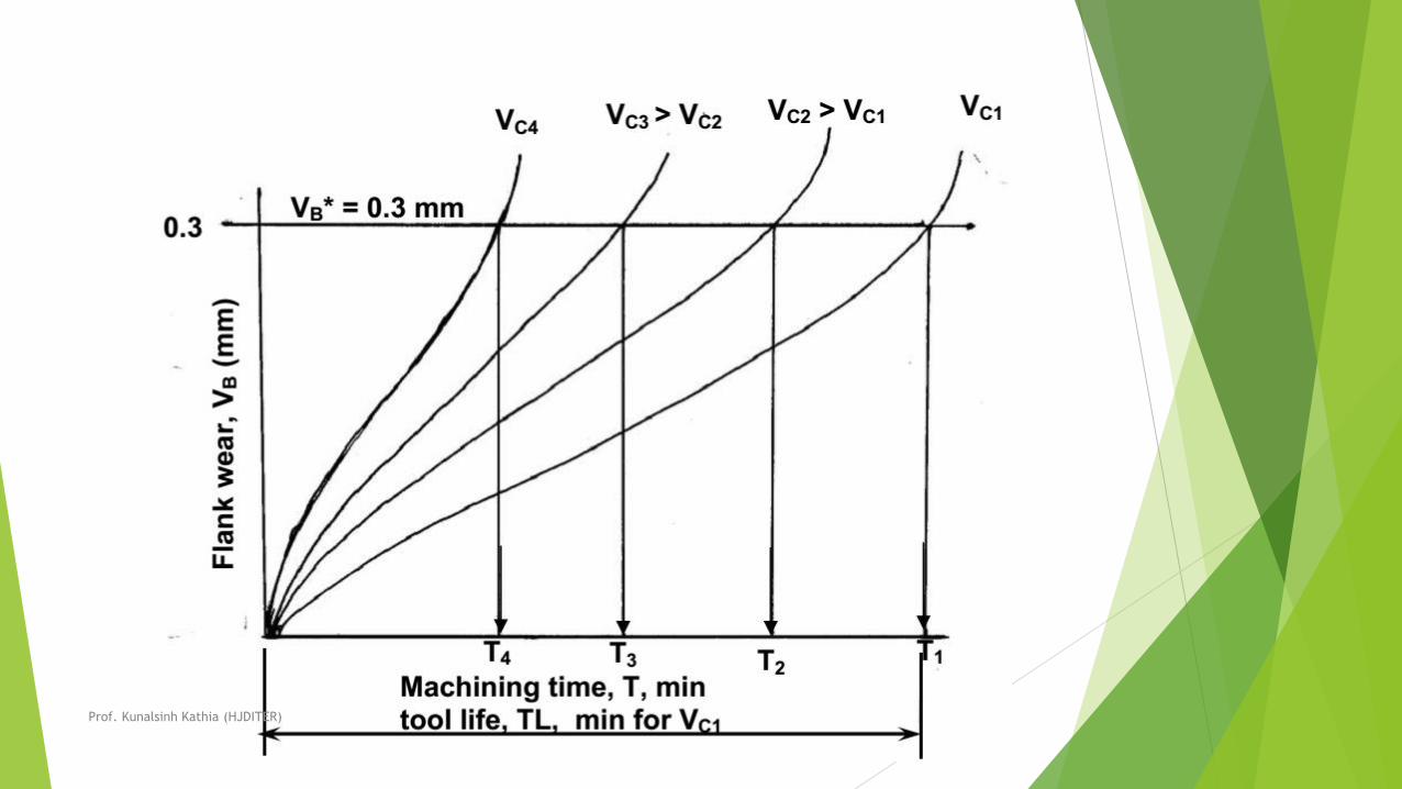
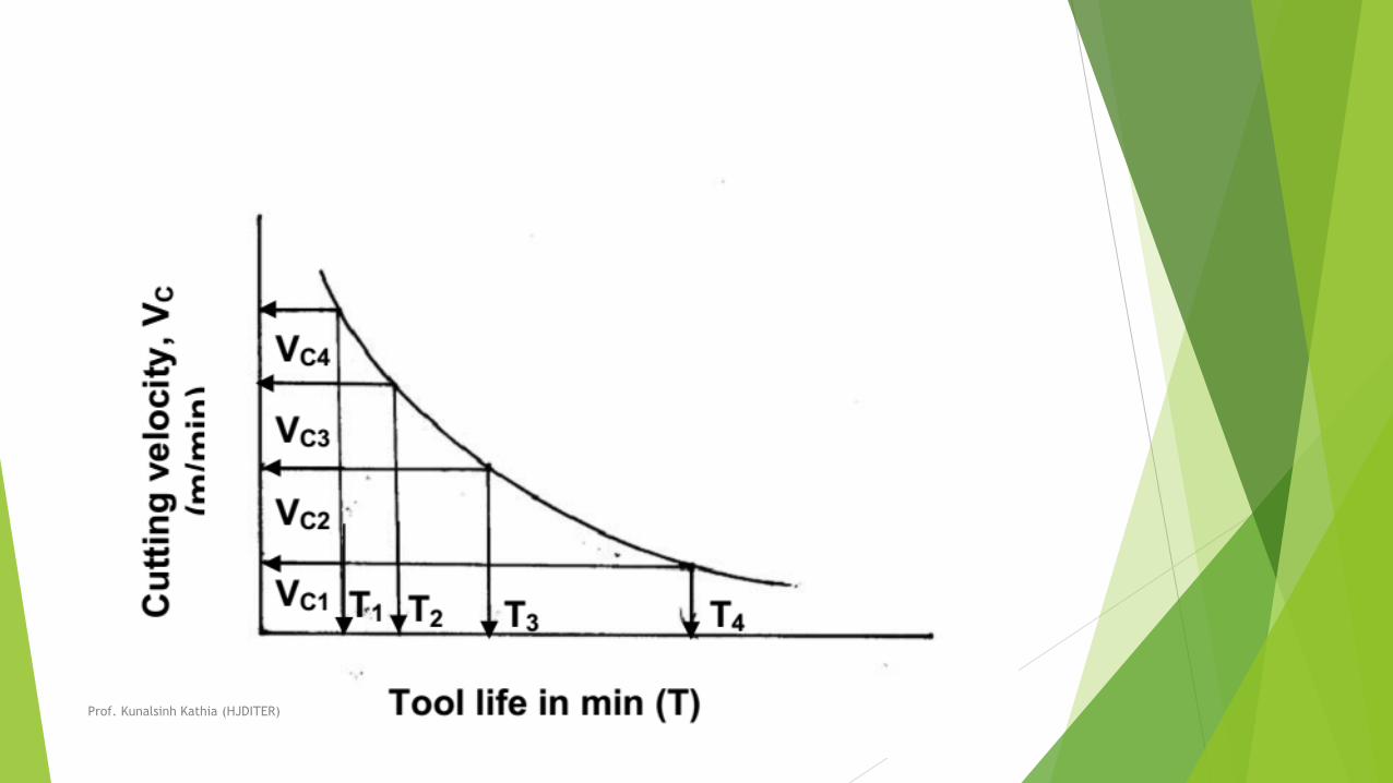
The usual pattern of growth of cutting tool wear (mainly VB), principle of
assessing tool life and its dependence on cutting velocity are schematically
shown in Fig.
The tool life obviously decreases with the increase in cutting velocity keeping
other conditions unaltered as indicated in Fig.
If the tool lives, T1, T2, T3, T4etc are plotted against the corresponding
cutting velocities, V1, V2, V3, V4etc as shown in Fig. 3.2.4, a smooth curve
like a rectangular hyperbola is found to appear.
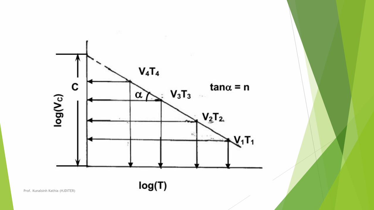
When F. W. Taylor plotted the same figure taking both V and T in log-scale, a
more distinct linear relationship appeared as schematically shown in Fig.
Prof. Kunalsinh Kathia (HJDITER)
Prof. Kunalsinh Kathia (HJDITER)
Prof. Kunalsinh Kathia (HJDITER)
With the slope, n and intercept, c, Taylor derived the simple equation as
where, n is called, Taylor’s tool life exponent. The values of both ‘n’ and ‘c’
depend mainly upon the tool-work materials and the cutting environment
(cutting fluid application). The value of C depends also on the limiting value
of V undertaken ( i.e., 0.3 mm, 0.4 mm, 0.6 mm etc.)
Prof. Kunalsinh Kathia (HJDITER)

Prof. Kunalsinh Kathia (HJDITER)

Prof. Kunalsinh Kathia (HJDITER)

Prof. Kunalsinh Kathia (HJDITER)

Prof. Kunalsinh Kathia (HJDITER)

Prof. Kunalsinh Kathia (HJDITER)

Prof. Kunalsinh Kathia (HJDITER)
Cutting tool geometryProduction Technology
Prof. Kunalsinh R. Kathia
Mechanical Engineering Department
Prof. Kunalsinh Kathia (HJDITER)
Geometry of single point turning tools
• Both material and geometry of the cutting tools play very important roles on their performances in achieving effectiveness, efficiency and overall economy of machining.
• Cutting tools may be classified according to the number of major cutting edges (points) involved as follows:
• Single point: e.g., turning tools, shaping, planning and slotting tools and boring tools
• Double (two) point: e.g., drills
• Multipoint (more than two): e.g., milling cutters, broaching tools, hobs, gear shaping cutters etc.
Prof. Kunalsinh Kathia (HJDITER)
Concept of rake and clearance angles of
cutting tools
• The word tool geometry is basically referred to some specific angles or slope
of the salient faces and edges of the tools at their cutting point.
• Rake angle and clearance angle are the most significant for all the cutting
tools.
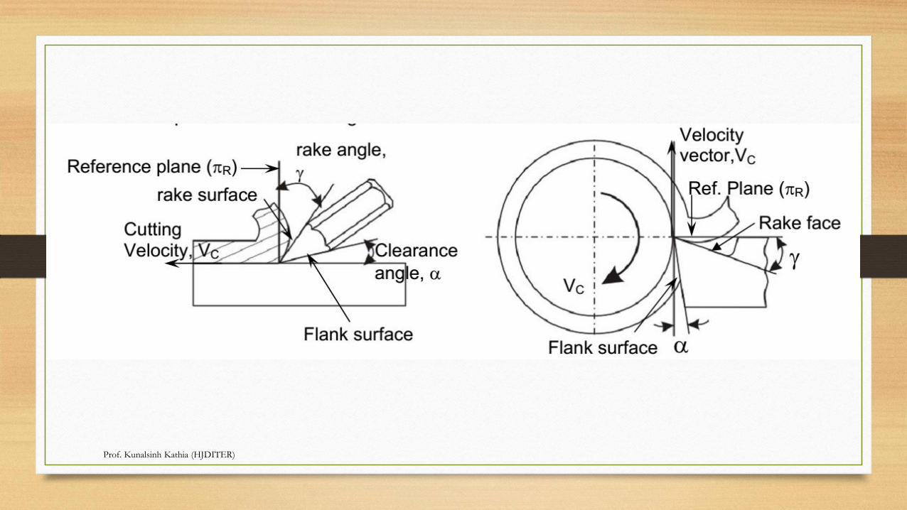
• The concept of rake angle and clearance angle will be clear from some
simple operations shown in Fig.
Prof. Kunalsinh Kathia (HJDITER)
Prof. Kunalsinh Kathia (HJDITER)
DEFINATION
• Rake angle (γ): Angle of inclination of rake surface from reference plane
• clearance angle (α): Angle of inclination of clearance or flank surface from
the finished surface
• Rake angle is provided for ease of chip flow and overall machining.
• Rake angle may be positive, or negative or even zero as shown in Fig..
Prof. Kunalsinh Kathia (HJDITER)
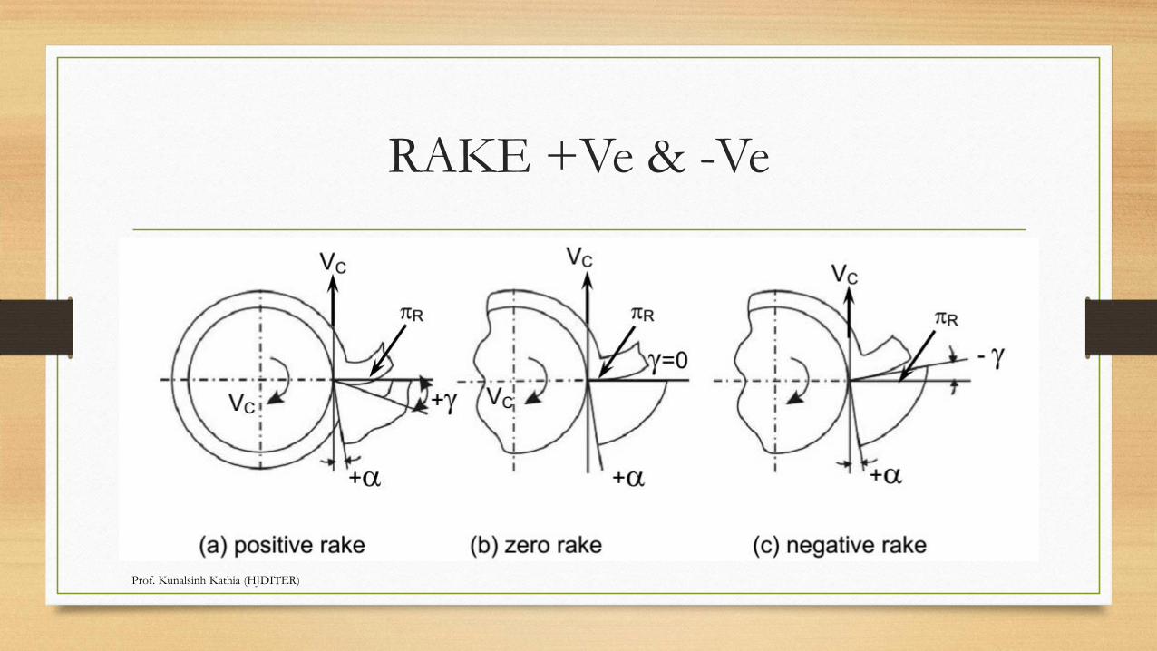
RAKE +Ve & -Ve
Prof. Kunalsinh Kathia (HJDITER)
ADVANTAGE
• Relative advantages of such rake angles are:
• • Positive rake – helps reduce cutting force and thus cutting power requirement.
• • Negative rake – to increase edge-strength and life of the tool
• • Zero rake – to simplify design and manufacture of the form tools.
• Clearance angle is essentially provided to avoid rubbing of the tool (flank) with themachined surface which causes loss of energy and damages of both the tool andthe job surface. Hence, clearance angle is a must and must be positive (3o~ 15o)depending upon tool-work materials and type of the machining operations liketurning, drilling, boring etc.)
Prof. Kunalsinh Kathia (HJDITER)
Systems of description of tool geometry
• • Tool-in-Hand System – where only the salient features of the cutting tool point are identified or visualized .
• There is no quantitative information, i.e., value of the angles.
• Machine Reference System – ASA system
• Tool Reference Systems
• Orthogonal Rake System – ORS
• Normal Rake System – NRS
• Work Reference System – WRS
Prof. Kunalsinh Kathia (HJDITER)
Machine Reference System
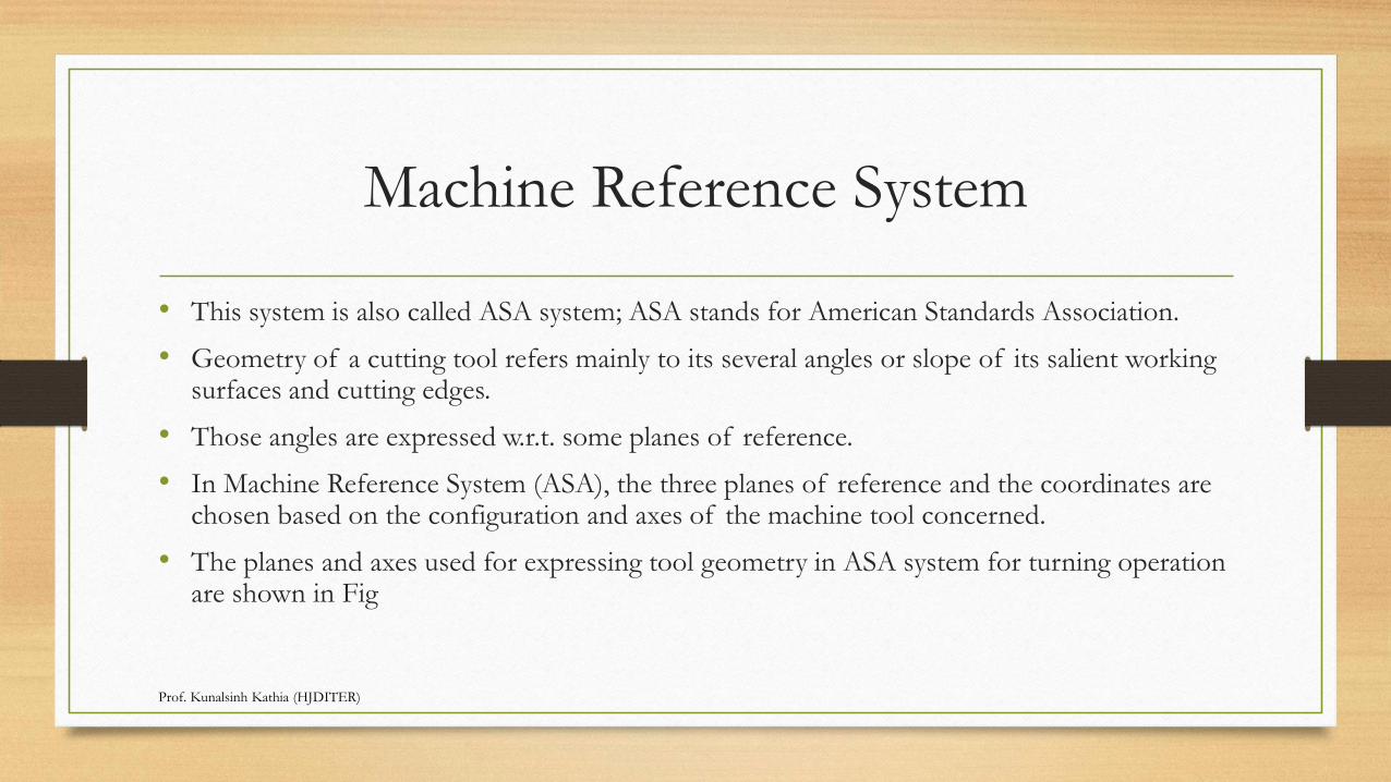
• This system is also called ASA system; ASA stands for American Standards Association.
• Geometry of a cutting tool refers mainly to its several angles or slope of its salient working surfaces and cutting edges.
• Those angles are expressed w.r.t. some planes of reference.
• In Machine Reference System (ASA), the three planes of reference and the coordinates are chosen based on the configuration and axes of the machine tool concerned.
• The planes and axes used for expressing tool geometry in ASA system for turning operation are shown in Fig
Prof. Kunalsinh Kathia (HJDITER)
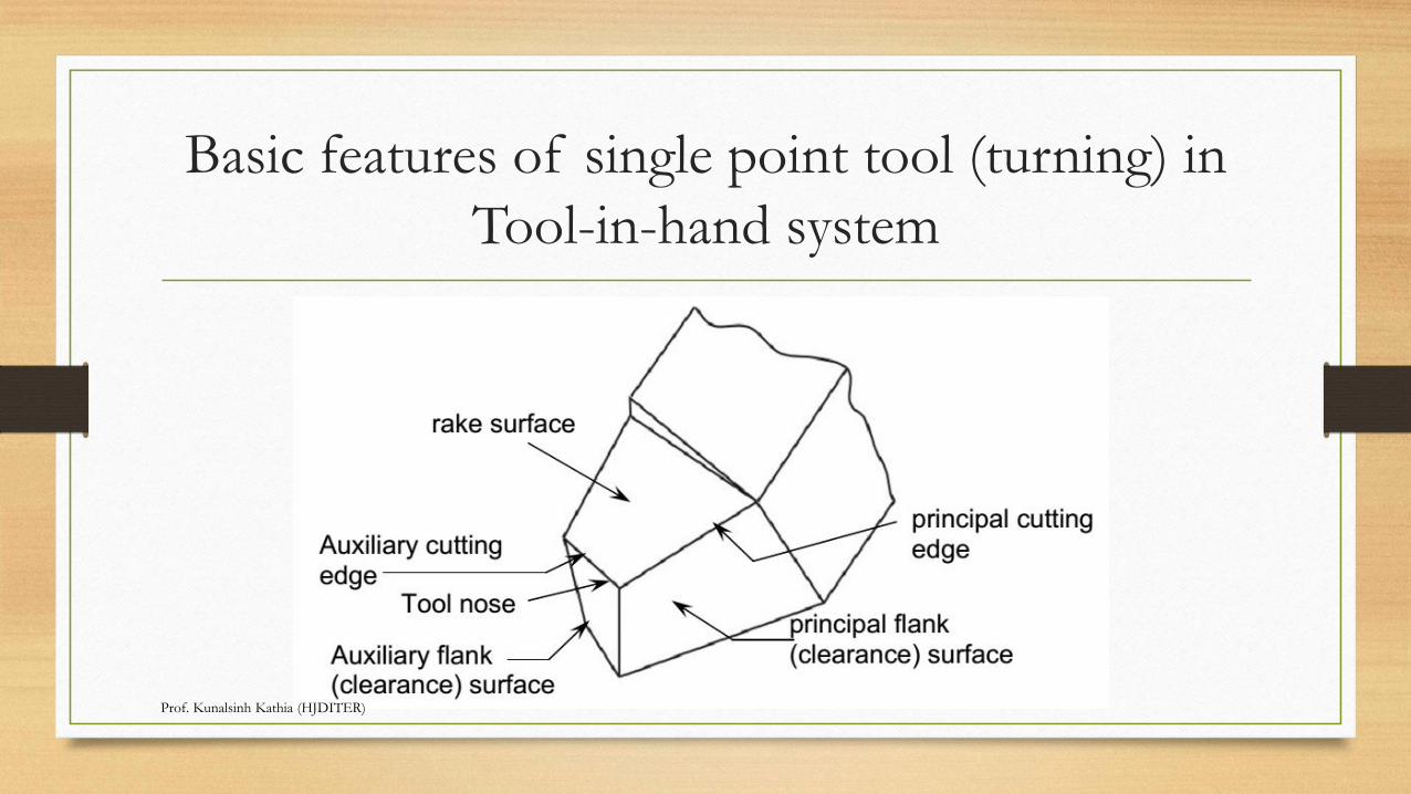
Basic features of single point tool (turning) in
Tool-in-hand system
Prof. Kunalsinh Kathia (HJDITER)
Prof. Kunalsinh Kathia (HJDITER)
Prof. Kunalsinh Kathia (HJDITER)
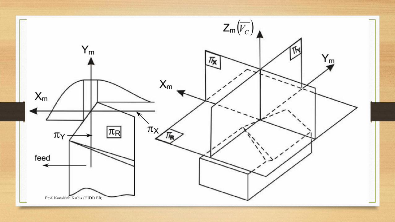
Denotations
• πR- πX- πY and Xm– Ym- Zm
• where,
• πR= Reference plane; plane perpendicular to the velocity vector
• πX = Machine longitudinal plane; plane perpendicular to πR and taken
• in the direction of assumed longitudinal feed
• πY= Machine Transverse plane; plane perpendicular to both πR and πX
Prof. Kunalsinh Kathia (HJDITER)
Denotations
• The axes Xm, Ym and Zm are in the direction of longitudinal feed, cross
feed
• and cutting velocity (vector) respectively. The main geometrical features and
• angles of single point tools in ASA systems and their definitions will be clear
from Fig
Prof. Kunalsinh Kathia (HJDITER)
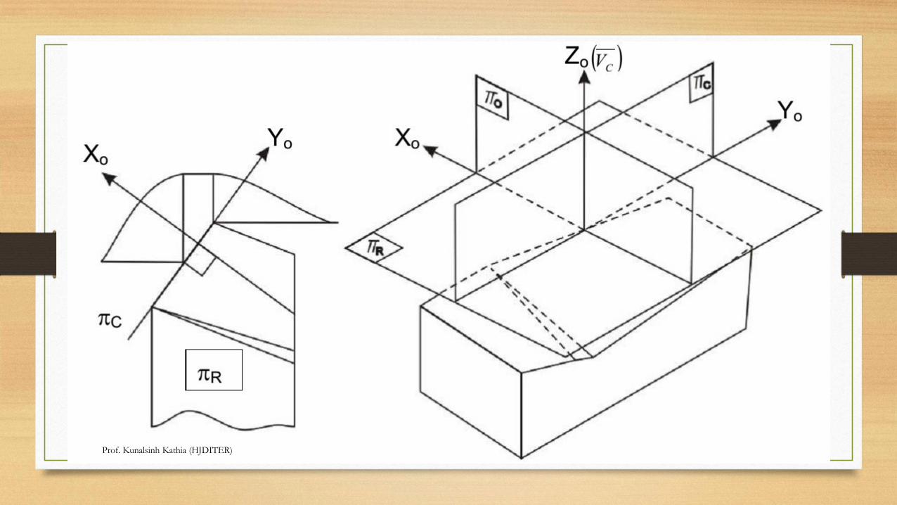
Tool Reference Systems
• Orthogonal Rake System – ORS
• This system is also known as ISO – old.
• The planes of reference and the co-ordinate axes used for expressing the
tool angles in ORS are:
• πR- πC- πO and Xo- Yo- Zo
• which are taken in respect of the tool configuration as indicated in Fig
Prof. Kunalsinh Kathia (HJDITER)
Prof. Kunalsinh Kathia (HJDITER)
Prof. Kunalsinh Kathia (HJDITER)
Normal Rake System – NRS
• This system is also known as ISO – new.
• ASA system has limited advantage and use like convenience of inspection.
• But ORS is advantageously used for analysis and research in machining and tool performance.
• But ORS does not reveal the true picture of the tool geometry when the cutting edges are inclined from the reference plane, i.e., λ≠0.
• Besides, sharpening or re sharpening, if necessary, of the tool by grinding in ORS requires some additional calculations for correction of angles.
Prof. Kunalsinh Kathia (HJDITER)
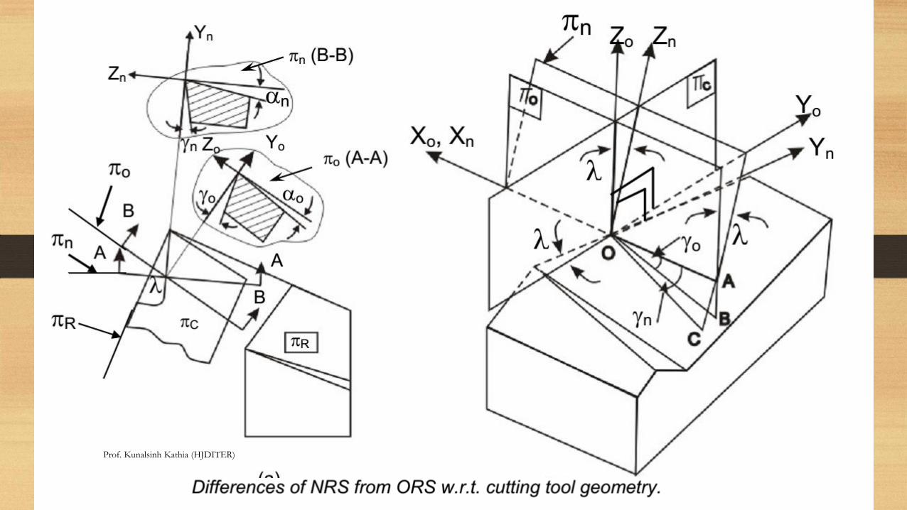
Normal Rake System – NRS
• These two limitations of ORS are overcome by using NRS for description and use of tool geometry.
• The basic difference between ORS and NRS is the fact that in ORS, rake and clearance angles are visualized in the orthogonal plane, πo, whereas in NRS those angles are visualized in another plane called Normal plane, πN.
• The orthogonal plane, πois simply normal to πRand πC irrespective of the inclination of the cutting edges, i.e., λ, but πN(and πN’ for auxiliary cutting edge) is always normal to the cutting edge.
• The differences between ORS and NRS have been depicted in Fig.
Prof. Kunalsinh Kathia (HJDITER)
Prof. Kunalsinh Kathia (HJDITER)
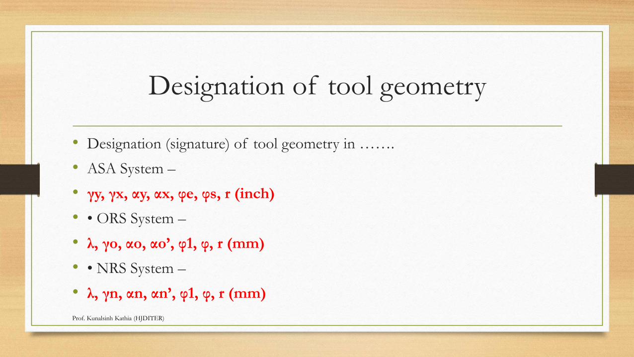
Designation of tool geometry
• Designation (signature) of tool geometry in …….
• ASA System –
• γy, γx, αy, αx, φe, φs, r (inch)
• • ORS System –
• λ, γo, αo, αo’, φ1, φ, r (mm)
• • NRS System –
• λ, γn, αn, αn’, φ1, φ, r (mm)
Prof. Kunalsinh Kathia (HJDITER)
Cutting tool materialsProduction Technology
Mr. Kunalsinh R. Kathia
M.E Machine Design
Mechanical Engineering Department
Mr. Kunalsinh Kathia (M.E Machine Design) Mechanical Engineering department
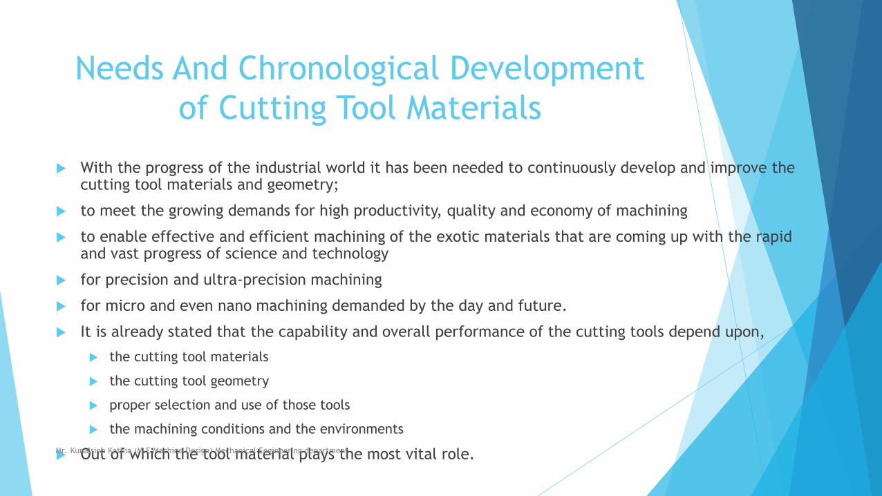
Needs And Chronological Development
of Cutting Tool Materials
With the progress of the industrial world it has been needed to continuously develop and improve the cutting tool materials and geometry;
to meet the growing demands for high productivity, quality and economy of machining
to enable effective and efficient machining of the exotic materials that are coming up with the rapid and vast progress of science and technology
for precision and ultra-precision machining
for micro and even nano machining demanded by the day and future.
It is already stated that the capability and overall performance of the cutting tools depend upon,
the cutting tool materials
the cutting tool geometry
proper selection and use of those tools
the machining conditions and the environments
Out of which the tool material plays the most vital role. Mr. Kunalsinh Kathia (M.E Machine Design) Mechanical Engineering department
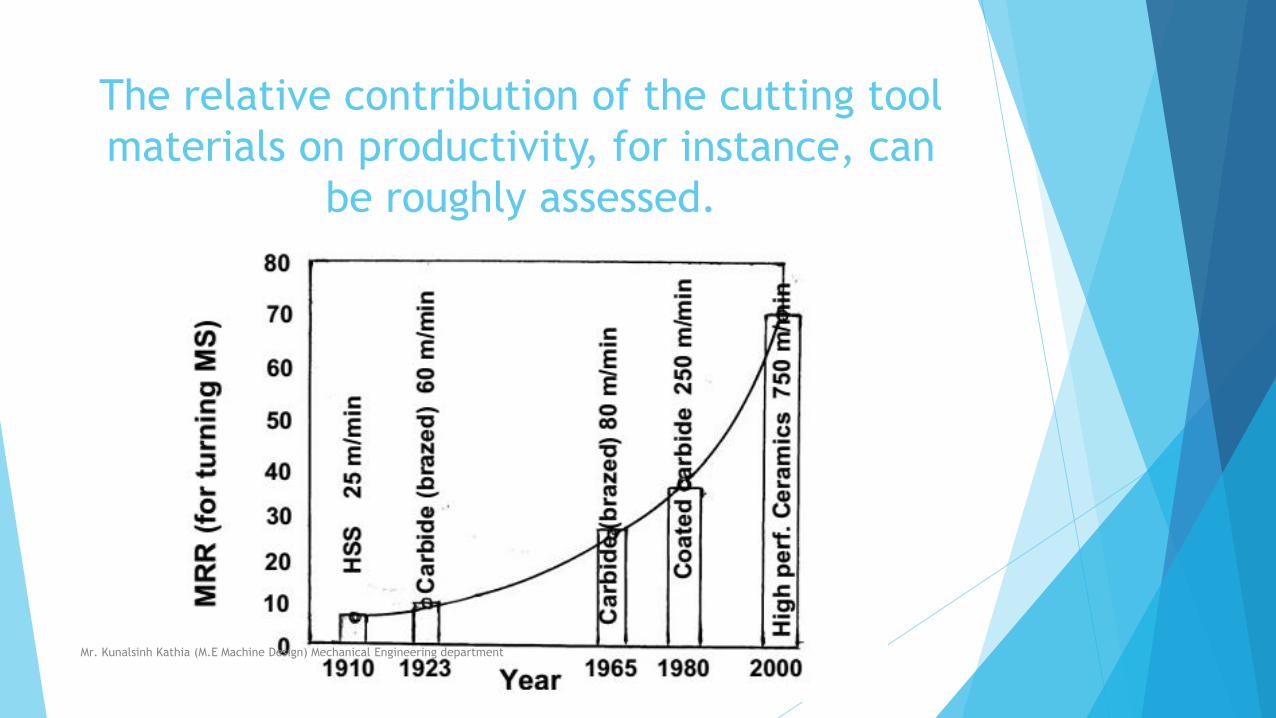
The relative contribution of the cutting tool
materials on productivity, for instance, can
be roughly assessed.
Mr. Kunalsinh Kathia (M.E Machine Design) Mechanical Engineering department
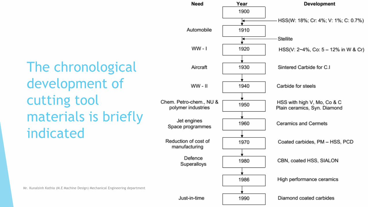
The chronological
development of
cutting tool
materials is briefly
indicated
Mr. Kunalsinh Kathia (M.E Machine Design) Mechanical Engineering department
Characteristics And Applications Of The
Primary Cutting Tool Materials
HSS (High speed steel)
Advent of HSS in around 1905 made a break through at that time in the
history of cutting tool materials though got later superseded by many other
novel tool materials like cemented carbides and ceramics which could
machine much faster than the HSS tools.
The basic composition of HSS is 18% W, 4% Cr, 1%V, 0.7% C and rest Fe.
Such HSS tool could machine (turn) mild steel jobs at speed only upto 20 ~
30m/min (which was quite substantial those days) .
Mr. Kunalsinh Kathia (M.E Machine Design) Mechanical Engineering department
HSS is still used as cutting tool material
where…..
the tool geometry and mechanics of chip formation are complex,
such as helical twist drills, reamers, gear shaping cutters, hobs, form tools, broaches etc.
• brittle tools like carbides, ceramics etc. are not suitable under shock loading
• the small scale industries cannot afford costlier tools
• the old or low powered small machine tools cannot accept high speed and feed.
• The tool is to be used number of times by re-sharpening.
Mr. Kunalsinh Kathia (M.E Machine Design) Mechanical Engineering department
HSS Nowadays improved with
following…..
• Refinement of microstructure
• Addition of large amount of cobalt and Vanadium to increase hot hardness
and wear resistance respectively
• Manufacture by powder metallurgical process
• Surface coating with heat and wear resistive materials like TiC, TiN, etc by
Chemical Vapour Deposition (CVD) or Physical Vapour Deposition (PVD)
Mr. Kunalsinh Kathia (M.E Machine Design) Mechanical Engineering department
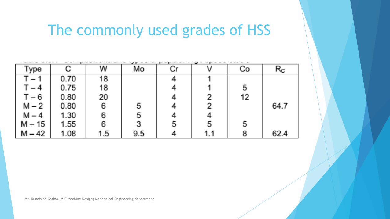
The commonly used grades of HSS
Mr. Kunalsinh Kathia (M.E Machine Design) Mechanical Engineering department
What these addition makes
Addition of large amount of Co and V,
refinement of microstructure and
coating increased strength and wear
resistance and thus enhanced
productivity and life of the HSS tools
remarkably
Mr. Kunalsinh Kathia (M.E Machine Design) Mechanical Engineering department
Stellite
This is a cast alloy of Co (40 to 50%), Cr (27 to 32%), W (14 to 19%) and C (2%).
Stellite is quite tough and more heat and wear resistive than the basic HSS
(18 – 4 – 1) But such stellite as cutting tool material became
obsolete for its poor grind ability and specially after the
arrival of cemented carbides.
Mr. Kunalsinh Kathia (M.E Machine Design) Mechanical Engineering department
Sintered Tungsten carbides
The advent of sintered carbides made
another breakthrough in the history of
cutting tool materials.
Straight or single carbide
Composite carbides
Mixed carbides
Mr. Kunalsinh Kathia (M.E Machine Design) Mechanical Engineering department
Straight or single carbide
First the straight or single carbide tools or inserts were
powder metallurgically produced by mixing, compacting
and sintering 90 to 95% WC powder with cobalt.
The hot, hard and wear resistant WC grains are held by
the binder Co which provides the necessary strength and
toughness.
Such tools are suitable for machining grey cast iron, brass,
bronze etc.
which produce short discontinuous chips and at cutting
velocities two to three times of that possible for HSS
tools.Mr. Kunalsinh Kathia (M.E Machine Design) Mechanical Engineering department
Composite carbides
The single carbide is not suitable for machining steels
because of rapid growth of wear, particularly crater wear,
by diffusion of Co and carbon from the tool to the chip
under the high stress and temperature bulk (plastic)
contact between the continuous chip and the tool
surfaces.
For machining steels successfully, another type called composite carbide have
been developed by adding (8 to 20%) a gamma phase to WC and Co mix.
The gamma phase is a mix of TiC, TiN, TaC, NiC etc. which are more diffusion
resistant than WC due to their more stability and less wettability by steel.
Mr. Kunalsinh Kathia (M.E Machine Design) Mechanical Engineering department
Mixed carbides
Titanium carbide (TiC) is not only more stable but also
much harder than WC.
So for machining ferritic steels causing intensive diffusion
and adhesion wear a large quantity (5 to 25%) of TiC is
added with WC and Co to produce another grade called
Mixed carbide. But increase in TiC content reduces the
toughness of the tools.
Therefore, for finishing with light cut but high speed, the
harder grades containing upto 25% TiC are used and for
heavy roughing work at lower speeds lesser amount (5 to
10%) of TiC is suitable.Mr. Kunalsinh Kathia (M.E Machine Design) Mechanical Engineering department
Gradation of cemented carbides and
their applications
Mr. Kunalsinh Kathia (M.E Machine Design) Mechanical Engineering department
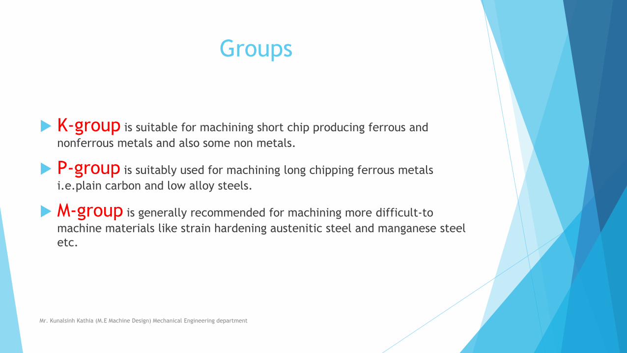
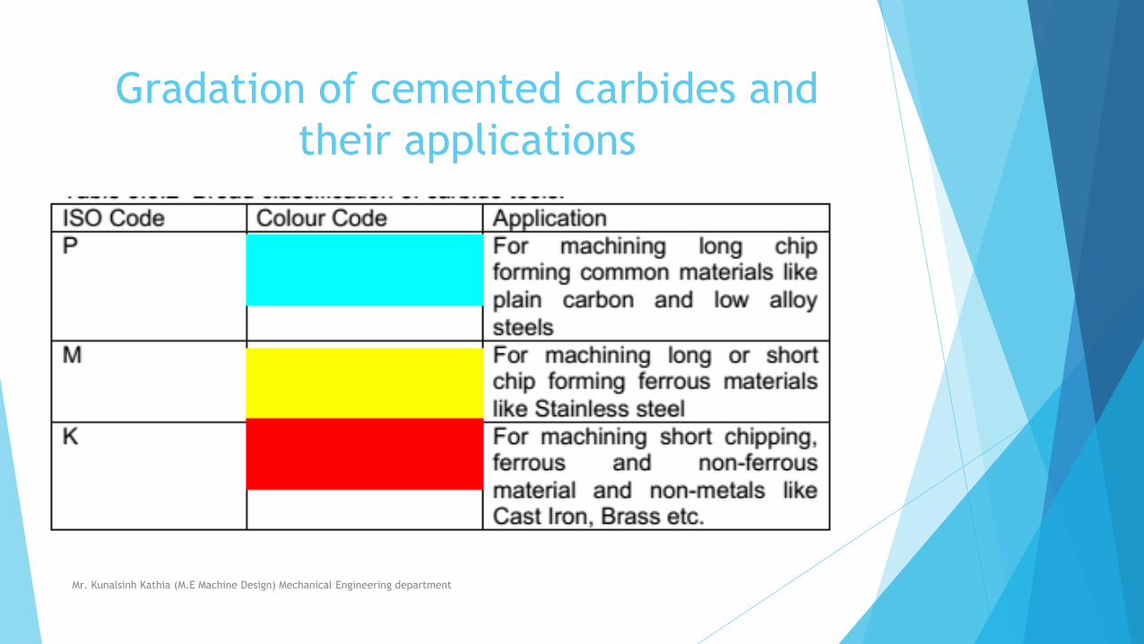
Groups
K-group is suitable for machining short chip producing ferrous and
nonferrous metals and also some non metals.
P-group is suitably used for machining long chipping ferrous metals
i.e.plain carbon and low alloy steels.
M-group is generally recommended for machining more difficult-to
machine materials like strain hardening austenitic steel and manganese steel
etc.
Mr. Kunalsinh Kathia (M.E Machine Design) Mechanical Engineering department
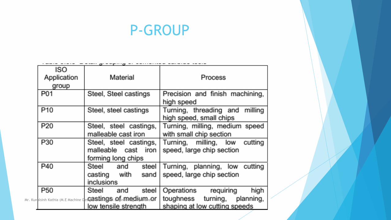
P-GROUP
Mr. Kunalsinh Kathia (M.E Machine Design) Mechanical Engineering department
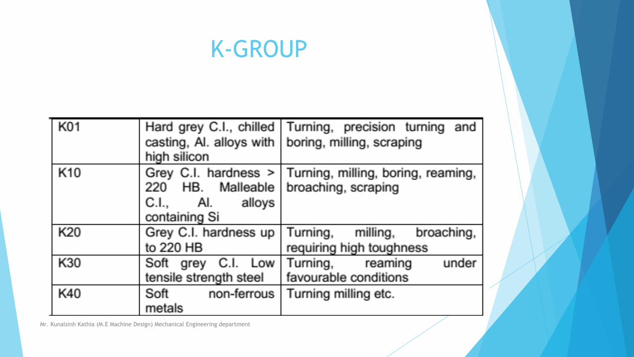
K-GROUP
Mr. Kunalsinh Kathia (M.E Machine Design) Mechanical Engineering department
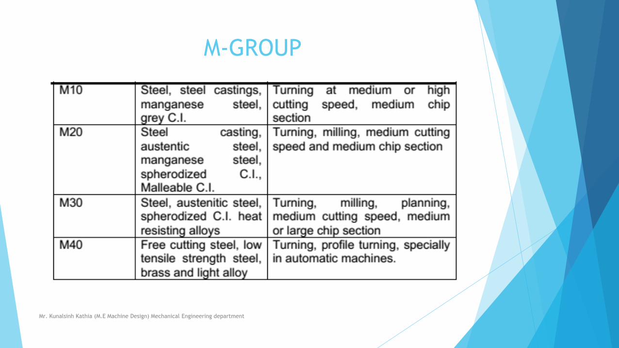
M-GROUP
Mr. Kunalsinh Kathia (M.E Machine Design) Mechanical Engineering department
NOTICABLE THING
The smaller number refers to the
operations which need more wear
resistance and the larger numbers
to those requiring higher toughness
for the tool.
Mr. Kunalsinh Kathia (M.E Machine Design) Mechanical Engineering department
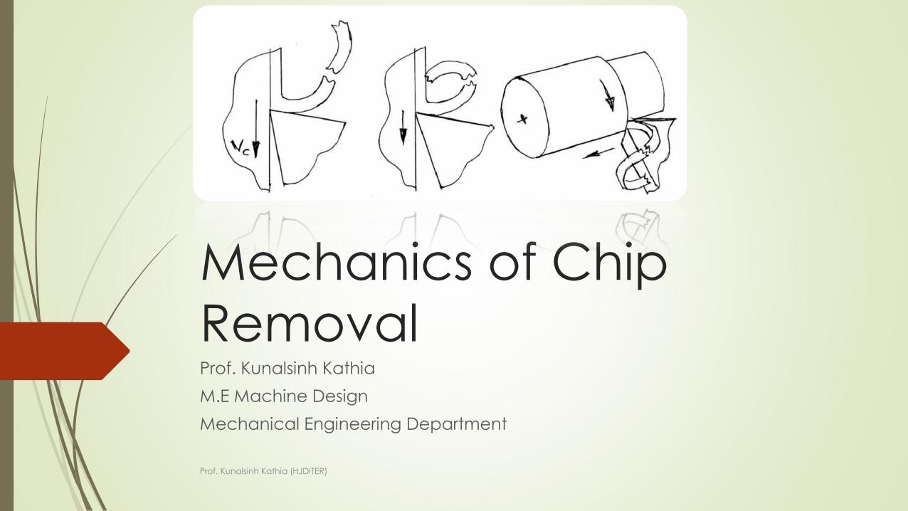
Mechanics of Chip
RemovalProf. Kunalsinh Kathia
M.E Machine Design
Mechanical Engineering Department
Prof. Kunalsinh Kathia (HJDITER)
Mechanism of chip formation in
machining
Machining is a semi-finishing or finishing process essentially done to impart
required or stipulated dimensional and form accuracy and surface finish to
enable the product to fulfill its basic functional requirements
provide better or improved performance
• render long service life.
Machining is a process of gradual removal of excess material from the
preformed blanks in the form of chips.
Prof. Kunalsinh Kathia (HJDITER)
What chip indicates?
Nature and behavior of the work material under
machining condition
Specific energy requirement (amount of energy required
to remove unit volume of work material) in machining
work
Nature and degree of interaction at the chip-tool
interfaces.
Prof. Kunalsinh Kathia (HJDITER)
The form of machined chips depend
mainly upon….
Work material
Material and geometry of the cutting tool
Levels of cutting velocity and feed and also to some extent on depth of
cut …
Machining environment or cutting fluid that affects temperature and
friction at the chip-tool and work-tool interfaces.
Prof. Kunalsinh Kathia (HJDITER)
Mechanism of chip formation in
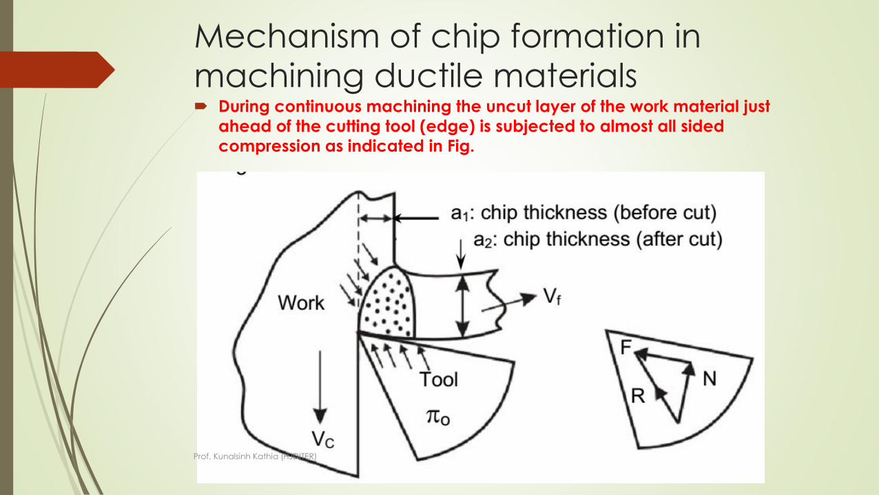
machining ductile materials During continuous machining the uncut layer of the work material just
ahead of the cutting tool (edge) is subjected to almost all sided
compression as indicated in Fig.
Prof. Kunalsinh Kathia (HJDITER)
The force exerted by the tool on the chipa rises out of the normal force, N and frictional force, F as indicated in Fig
Due to such compression, shear stress develops, within that compressed region, in different magnitude, in different directions and rapidly increases in magnitude.
Whenever and wherever the value of the shear stress reaches or exceeds the shear strength of that work material in the deformation region, yielding or slip takes place resulting shear deformation in that region and the plane of maximum shear stress.
But the forces causing the shear stresses in the region of the chip quickly diminishes and finally disappears while that region moves along the tool rake surface towards and then goes beyond the point of chip-tool engagement.
As a result the slip or shear stops propagating long before total separation takes place.
In the mean time the succeeding portion of the chip starts undergoing compression followed by yielding and shear.
This phenomenon repeats rapidly resulting in formation and removal of chips in thin layer by layer.
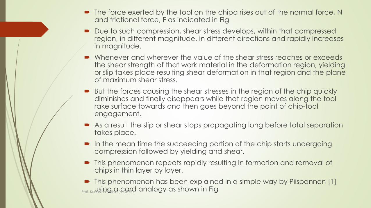
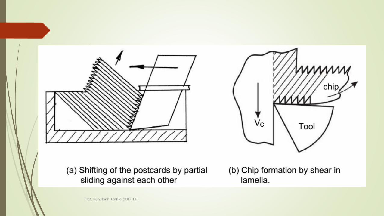
This phenomenon has been explained in a simple way by Piispannen [1] using a card analogy as shown in FigProf. Kunalsinh Kathia (HJDITER)
Prof. Kunalsinh Kathia (HJDITER)
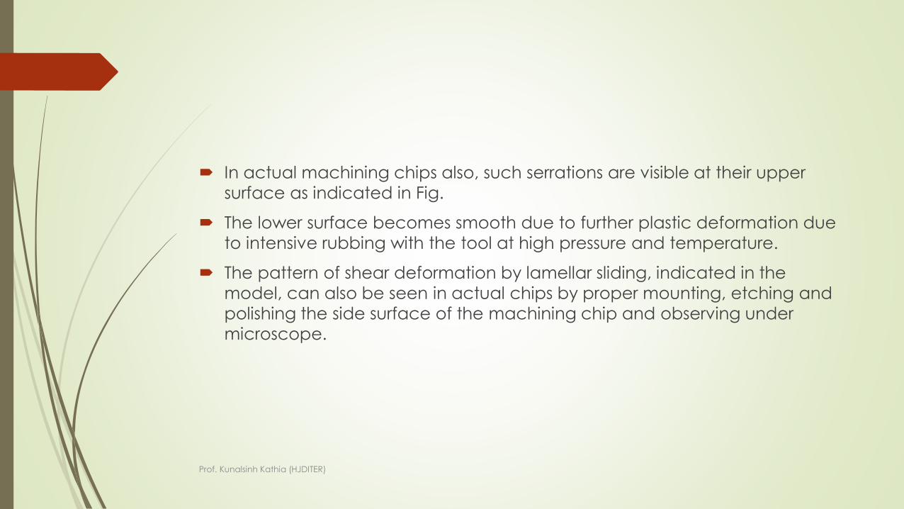
In actual machining chips also, such serrations are visible at their upper
surface as indicated in Fig.
The lower surface becomes smooth due to further plastic deformation due
to intensive rubbing with the tool at high pressure and temperature.
The pattern of shear deformation by lamellar sliding, indicated in the
model, can also be seen in actual chips by proper mounting, etching and
polishing the side surface of the machining chip and observing under
microscope.
Prof. Kunalsinh Kathia (HJDITER)
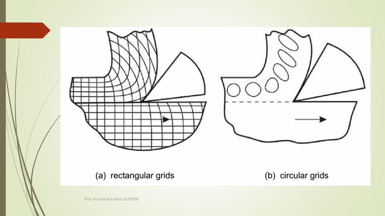
Experimental methods
The overall deformation process causing chip formation is quite complex and
hence needs thorough experimental studies for clear understanding the
phenomena and its dependence on the affecting parameters.
The feasible and popular experimental methods for this purpose are:
Study of deformation of rectangular or circular grids marked on the side surface
Prof. Kunalsinh Kathia (HJDITER)
Prof. Kunalsinh Kathia (HJDITER)
It has been established by several analyticaland experimental methods including circulargrid deformation that though the chips areinitially compressed ahead of the tool tip, thefinal deformation is accomplished mostly byshear in machining ductile materials. However,machining of ductile materials generallyproduces flat, curved or coiled continuouschips.
Prof. Kunalsinh Kathia (HJDITER)
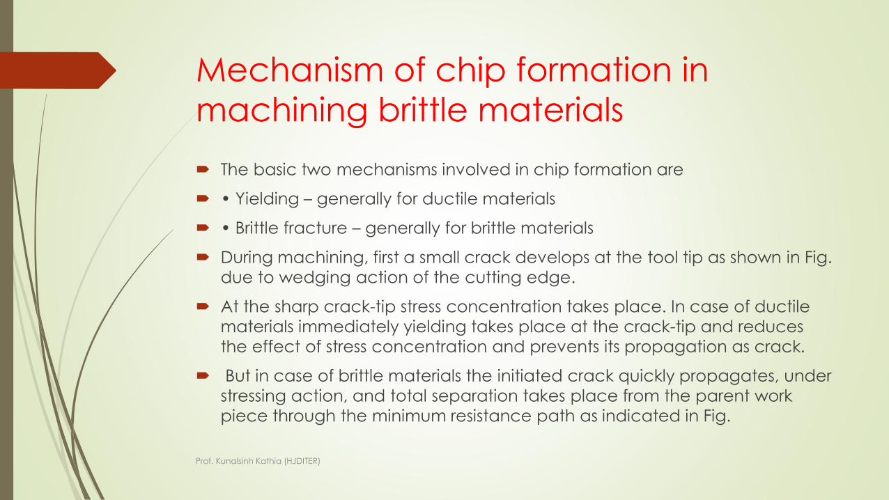
Mechanism of chip formation in
machining brittle materials
The basic two mechanisms involved in chip formation are
• Yielding – generally for ductile materials
• Brittle fracture – generally for brittle materials
During machining, first a small crack develops at the tool tip as shown in Fig.
due to wedging action of the cutting edge.
At the sharp crack-tip stress concentration takes place. In case of ductile
materials immediately yielding takes place at the crack-tip and reduces
the effect of stress concentration and prevents its propagation as crack.
But in case of brittle materials the initiated crack quickly propagates, under
stressing action, and total separation takes place from the parent work
piece through the minimum resistance path as indicated in Fig.
Prof. Kunalsinh Kathia (HJDITER)
Development and propagation of
crack causing chip separation
Prof. Kunalsinh Kathia (HJDITER)
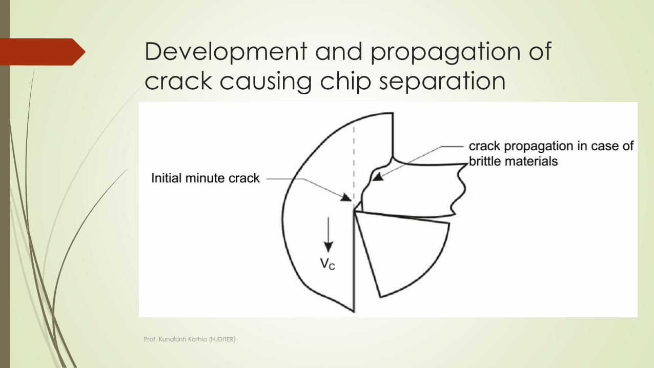
Machining of brittle material produces discontinuous chips and mostly of
irregular size and shape. The process of forming such chips is schematically
shown in Fig
Prof. Kunalsinh Kathia (HJDITER)
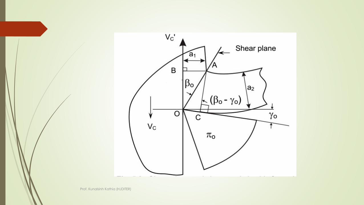
Chip thickness ratio
Shear angle :It has been observed that during machining, particularly
ductile materials, the chip sharply changes its direction of flow (relative to
the tool) from the direction of the cutting velocity, VC to that along the tool
rake surface after thickening by shear deformation or slip or lamellar sliding
along a plane. This plane is called shear plane and is schematically shown
in Fig.
Shear plane : Shear plane is the plane of separation of work material layer
in the form of chip from the parent body due to shear along that plane.
Shear angle : Angle of inclination of the shear plane from the direction ofcutting velocity
Prof. Kunalsinh Kathia (HJDITER)
Prof. Kunalsinh Kathia (HJDITER)

Prof. Kunalsinh Kathia (HJDITER)
JIGS & FIXTURESCLAMPING DEVICES
Production Technology
Mr. Kunalsinh Kathia
Mechanical Engineering
Department
PROF. KUNALSINH KATHIA (HJDITER)

CLAMPING DEVICES
1. Screw clamps
2. Hook bolt clamps
3. Lever type clamps
4. Wedge clamps
5. Quick action clamps
6. Power clamps
PROF. KUNALSINH KATHIA (HJDITER)
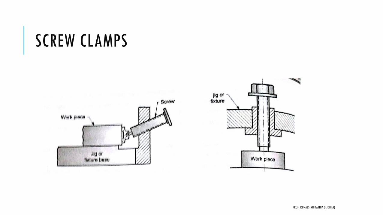
SCREW CLAMPS
PROF. KUNALSINH KATHIA (HJDITER)
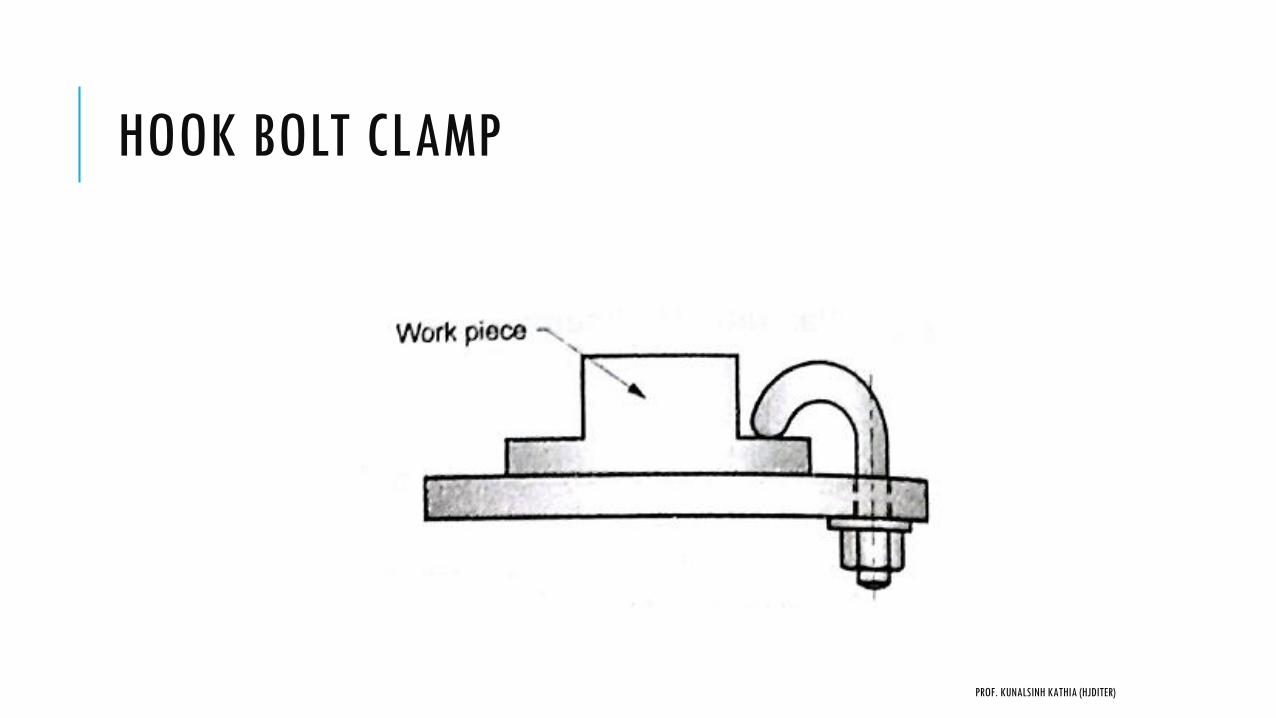
HOOK BOLT CLAMP
PROF. KUNALSINH KATHIA (HJDITER)

LEVER TYPE CLAMP
1. Simple Bridge type clamp
2. Edge clamp
3. Heel Clamp
4. Latch Clamp
5. Hinged Clamp
PROF. KUNALSINH KATHIA (HJDITER)
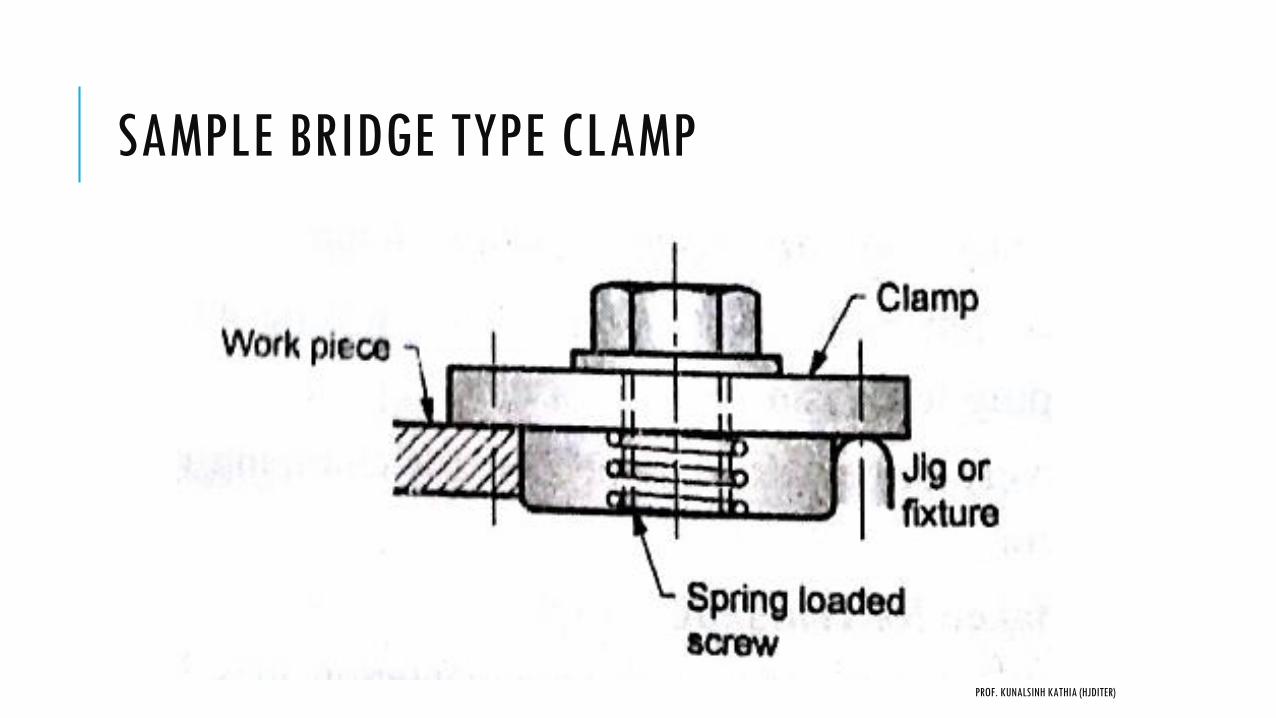
SAMPLE BRIDGE TYPE CLAMP
PROF. KUNALSINH KATHIA (HJDITER)
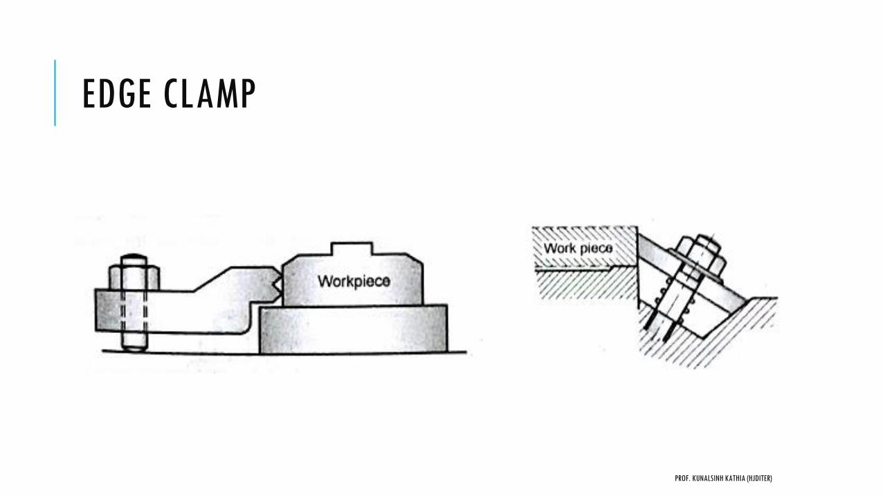
EDGE CLAMP
PROF. KUNALSINH KATHIA (HJDITER)
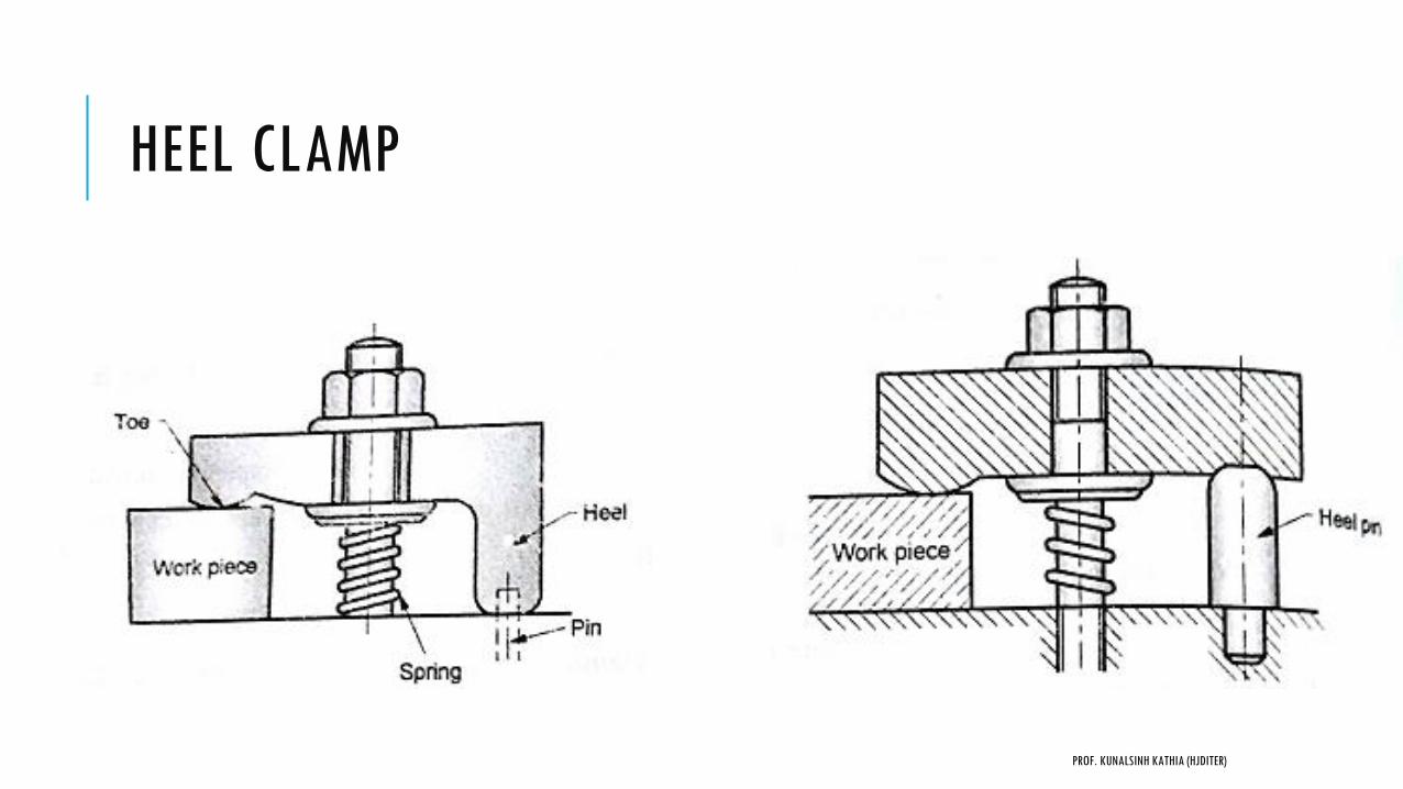
HEEL CLAMP
PROF. KUNALSINH KATHIA (HJDITER)
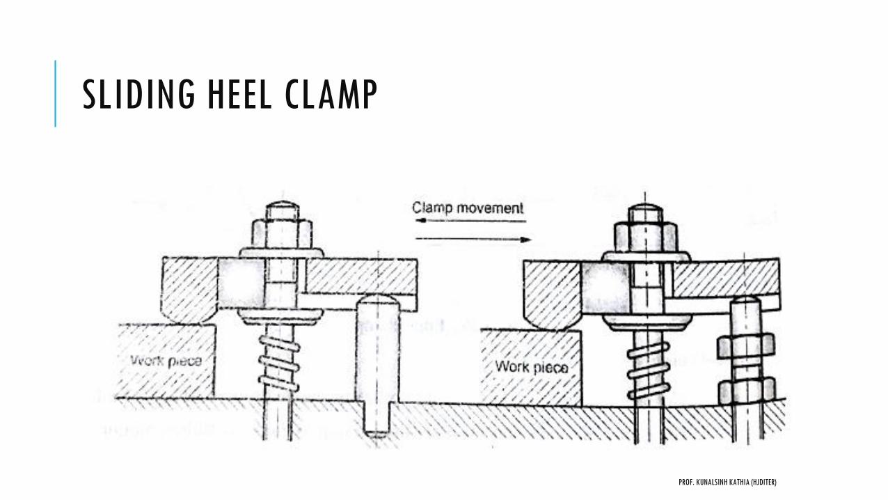
SLIDING HEEL CLAMP
PROF. KUNALSINH KATHIA (HJDITER)

LATCH CLAMP
Swinging latch clamp:
PROF. KUNALSINH KATHIA (HJDITER)
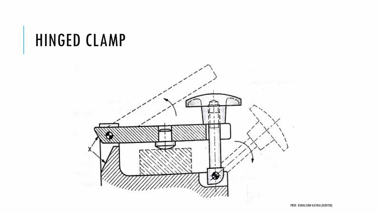
HINGED CLAMP
PROF. KUNALSINH KATHIA (HJDITER)
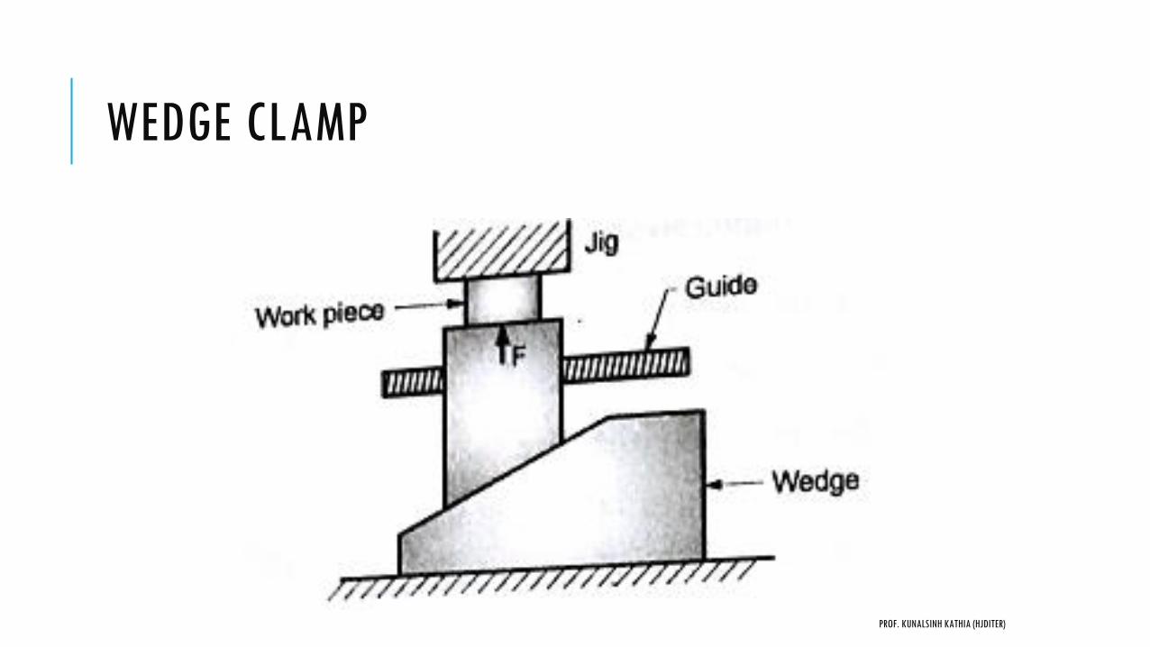
WEDGE CLAMP
PROF. KUNALSINH KATHIA (HJDITER)
QUICK ACTION CLAMPS
1. Swing washers and C washer clamps
2. Quick action nuts
3. Cam operated clamps
4. Toggle operated clamp
5. Bayonet clamp
PROF. KUNALSINH KATHIA (HJDITER)

SWING WASHER CLAMP
PROF. KUNALSINH KATHIA (HJDITER)
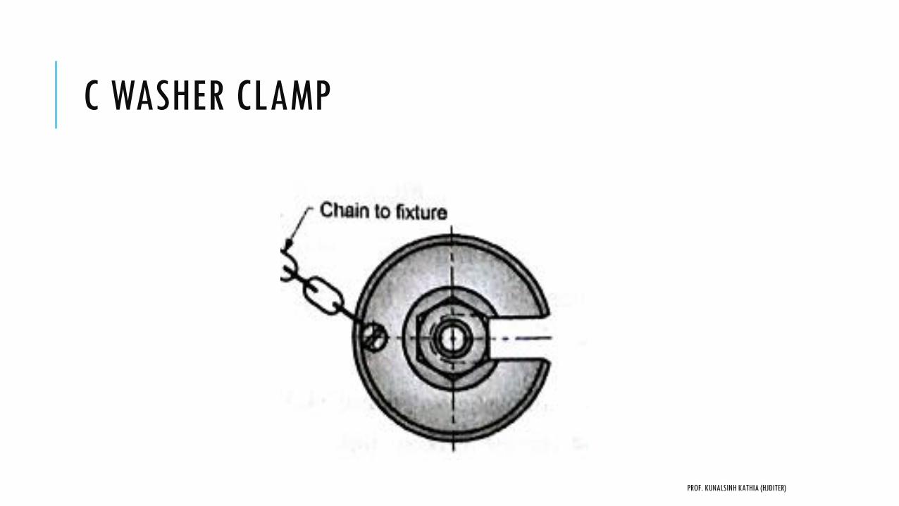
C WASHER CLAMP
PROF. KUNALSINH KATHIA (HJDITER)
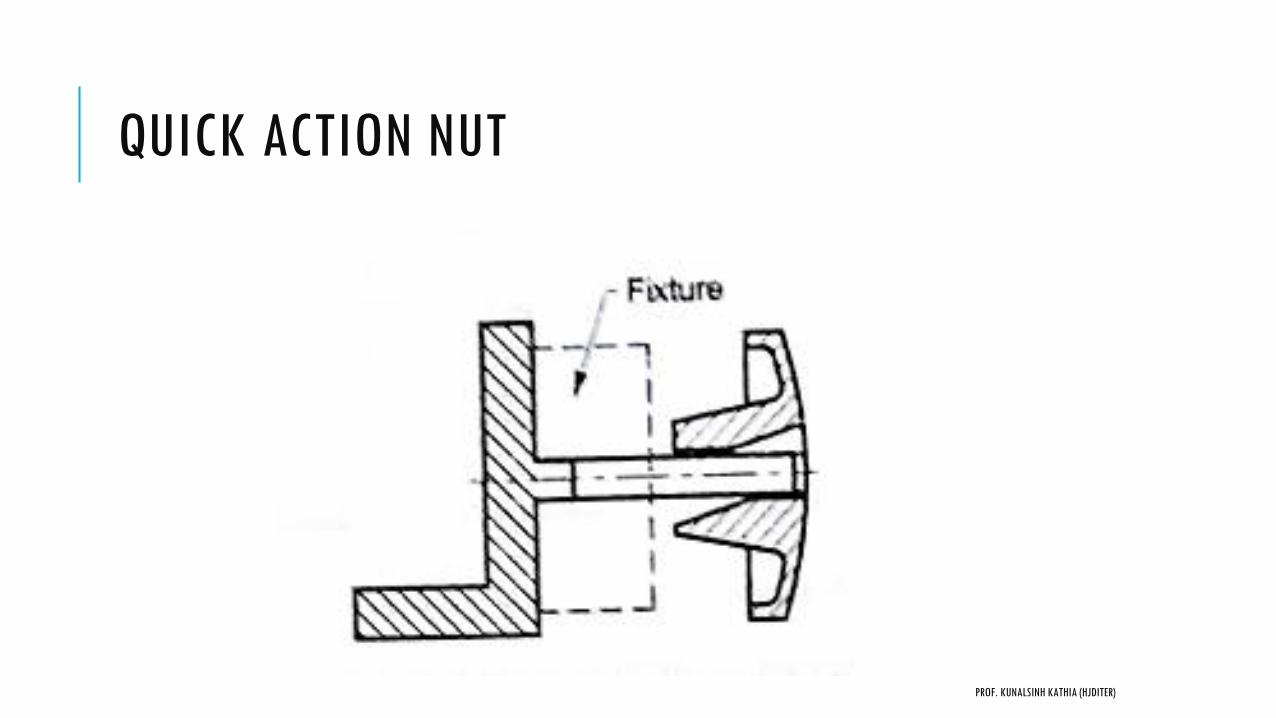
QUICK ACTION NUT
PROF. KUNALSINH KATHIA (HJDITER)
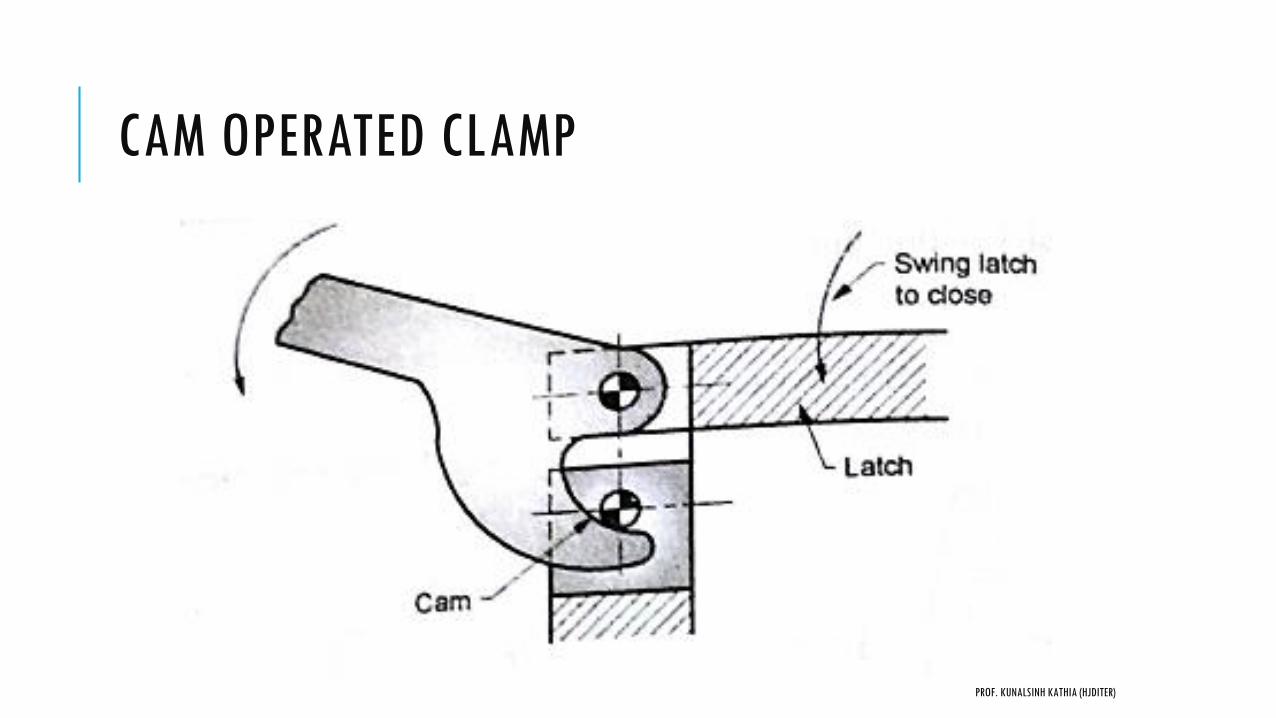
CAM OPERATED CLAMP
PROF. KUNALSINH KATHIA (HJDITER)
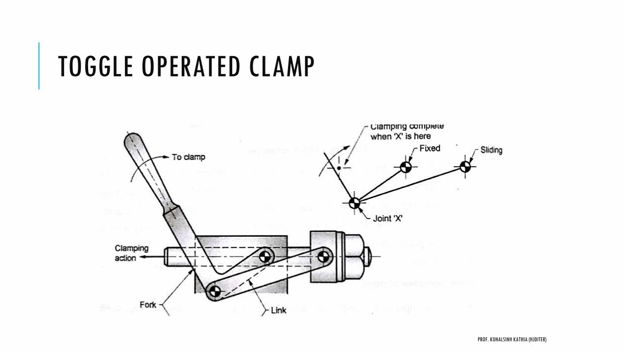
TOGGLE OPERATED CLAMP
PROF. KUNALSINH KATHIA (HJDITER)
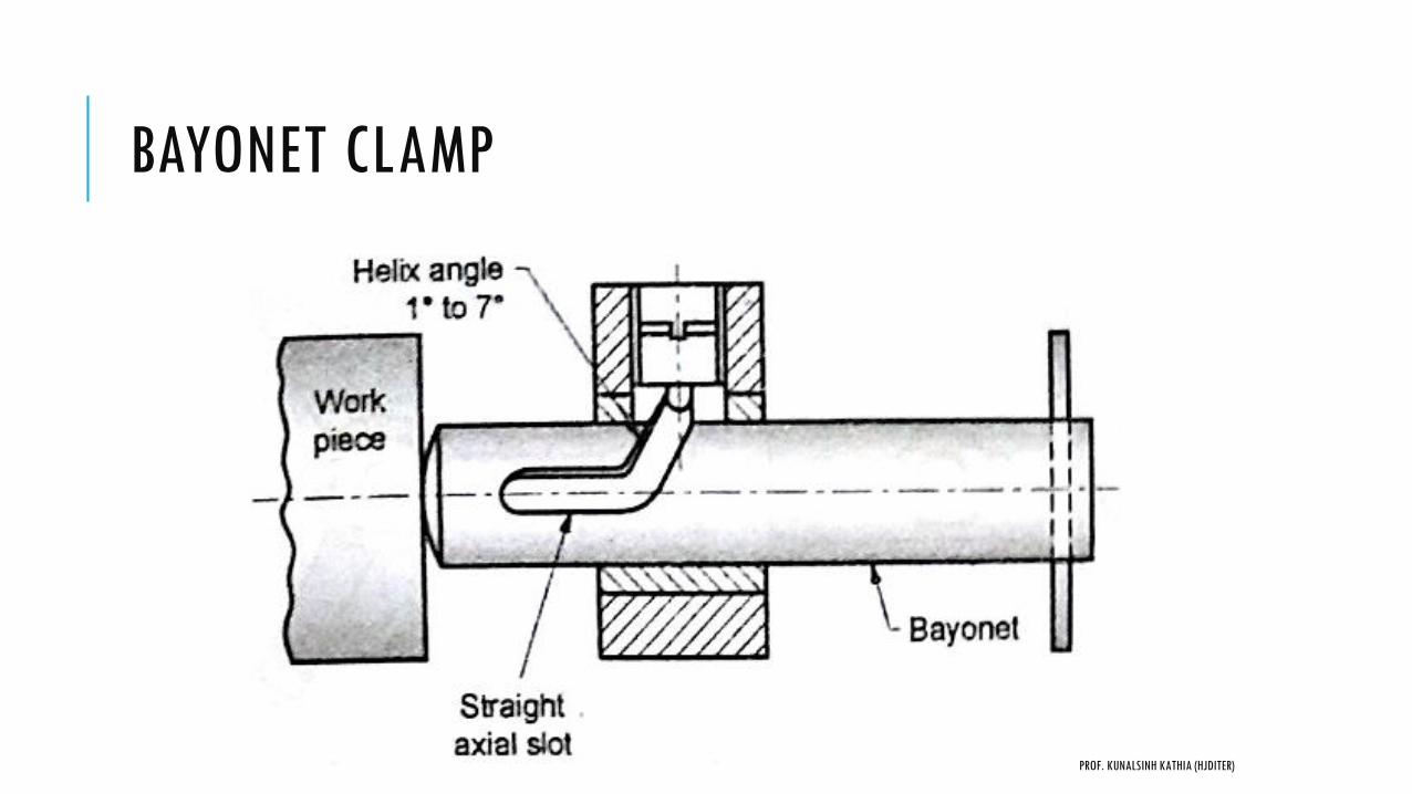
BAYONET CLAMP
PROF. KUNALSINH KATHIA (HJDITER)
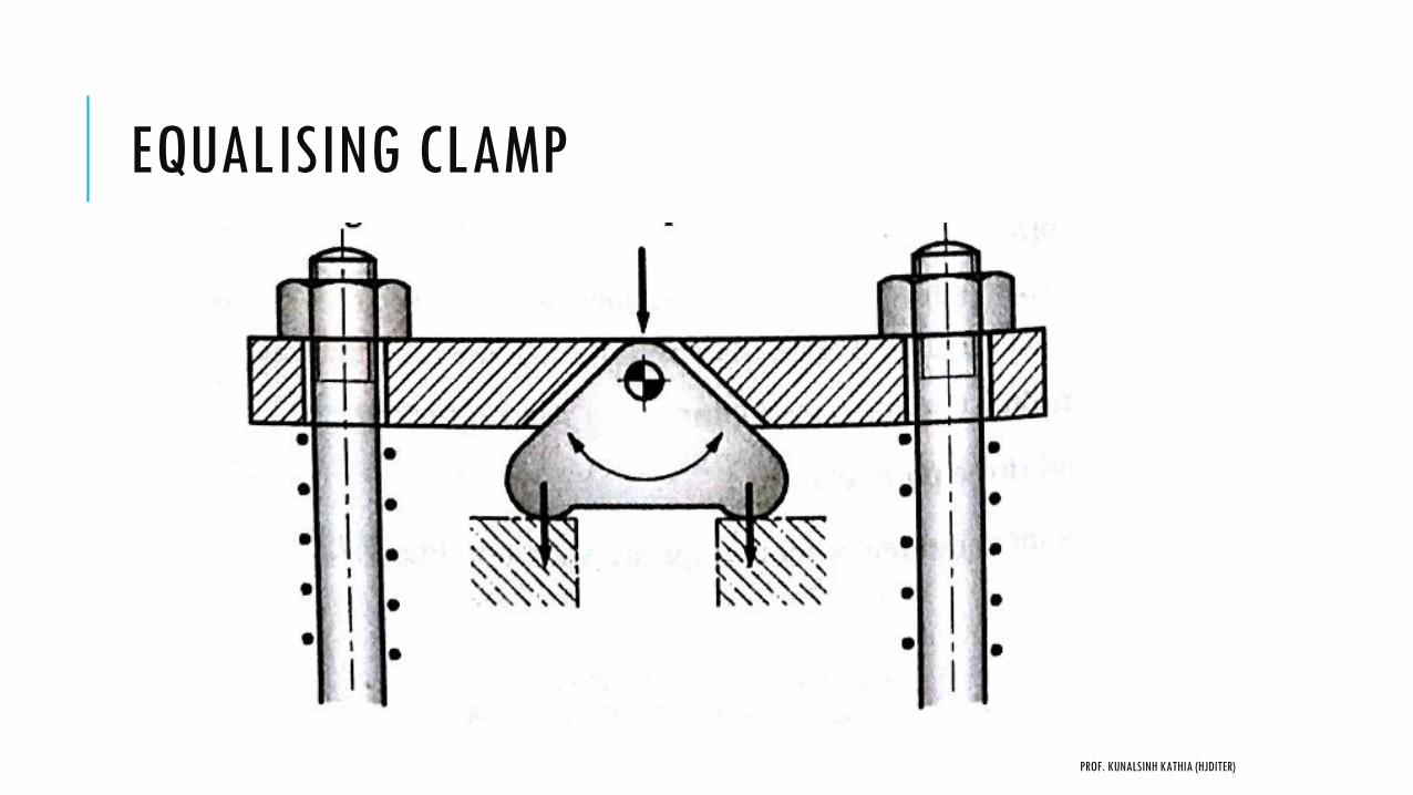
EQUALISING CLAMP
PROF. KUNALSINH KATHIA (HJDITER)
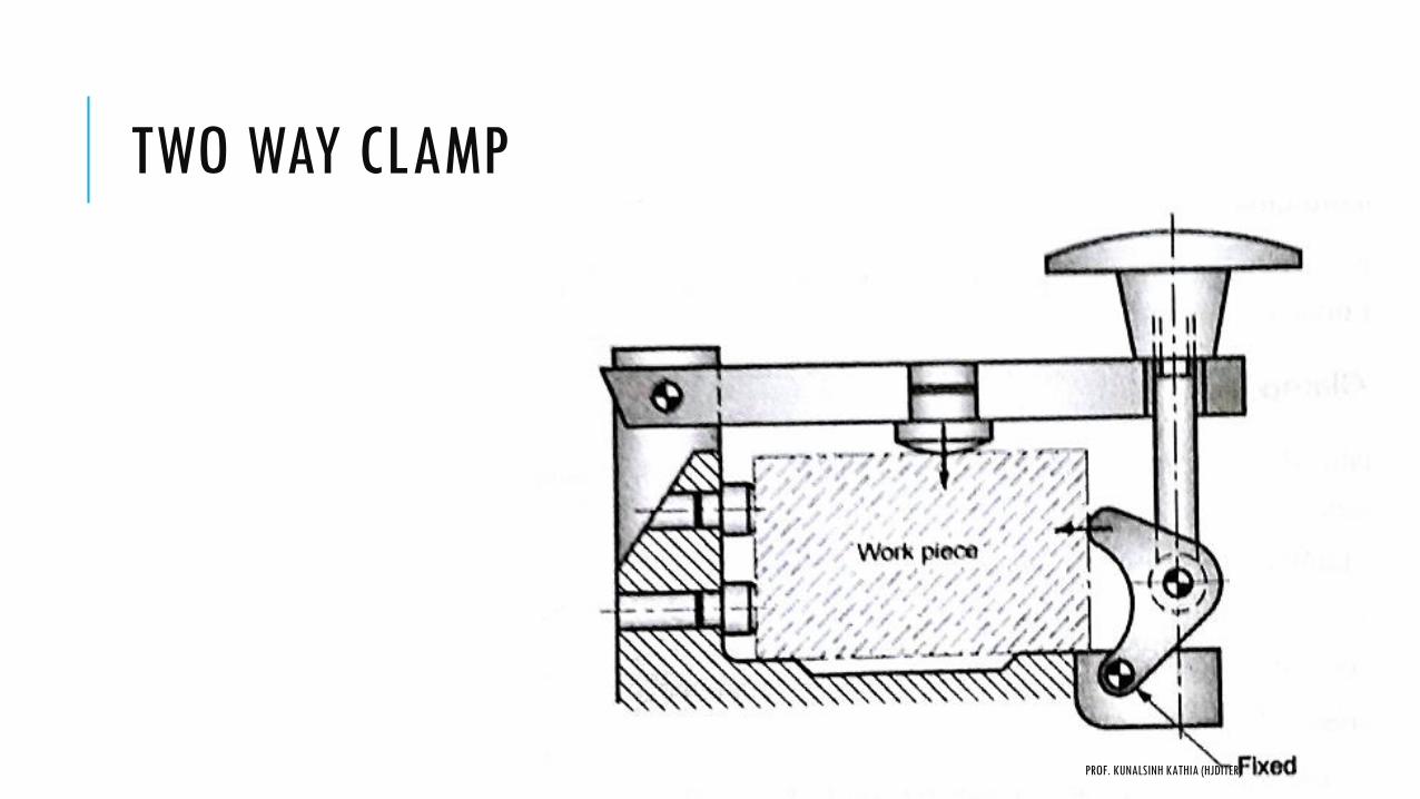
TWO WAY CLAMP
PROF. KUNALSINH KATHIA (HJDITER)

POWER CLAMPING
PROF. KUNALSINH KATHIA (HJDITER)
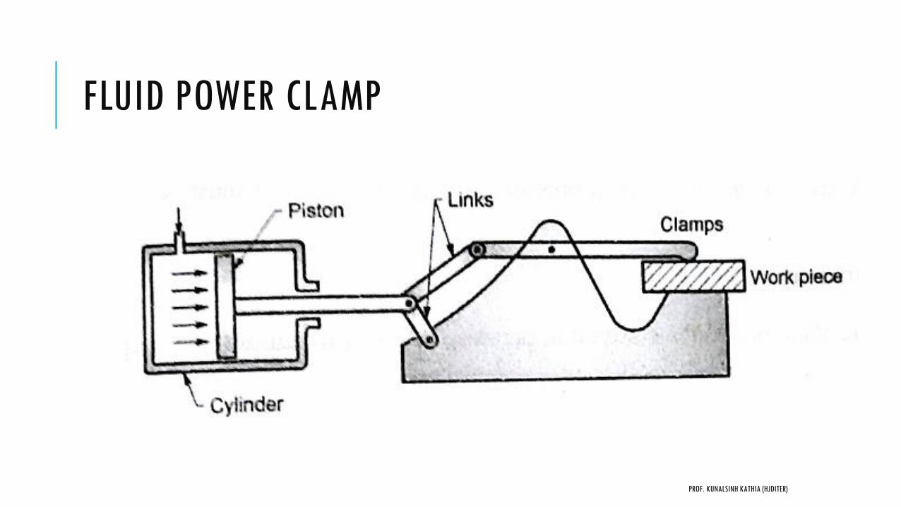
FLUID POWER CLAMP
PROF. KUNALSINH KATHIA (HJDITER)
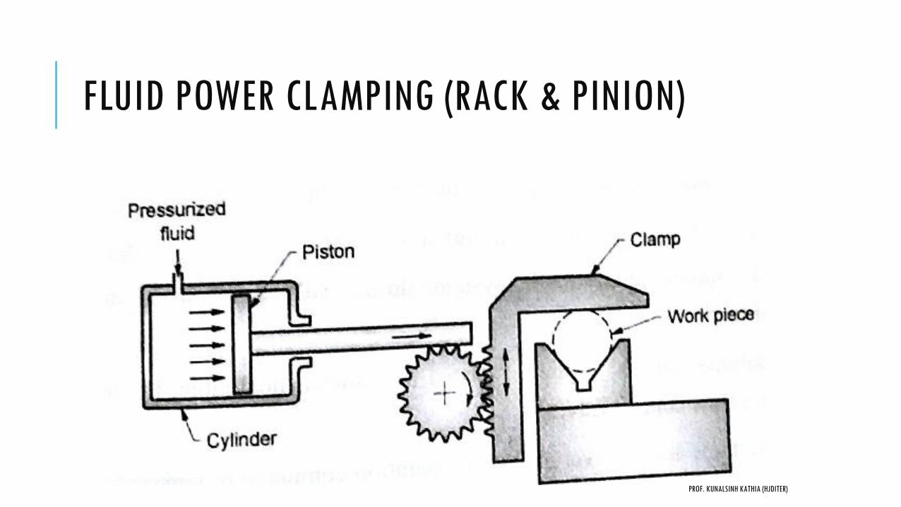
FLUID POWER CLAMPING (RACK & PINION)
PROF. KUNALSINH KATHIA (HJDITER)

AIR TO HYDRAULIC BOOSTER
PROF. KUNALSINH KATHIA (HJDITER)

JIGS & FIXTURES
Production technology
Prof. Kunalsinh kathia
Mechanical engineering department
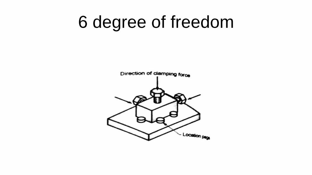
6 degree of freedom
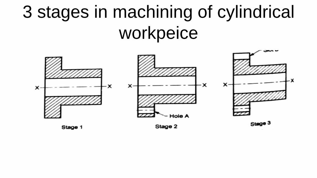
3 stages in machining of cylindrical
workpeice
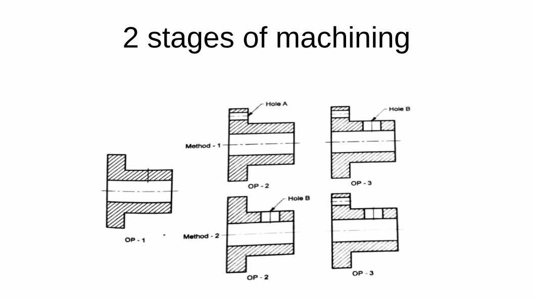
2 stages of machining
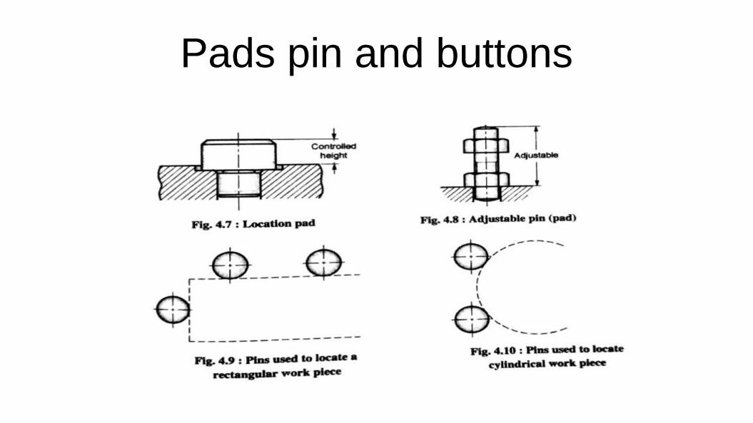
Pads pin and buttons

Cylindrical locators
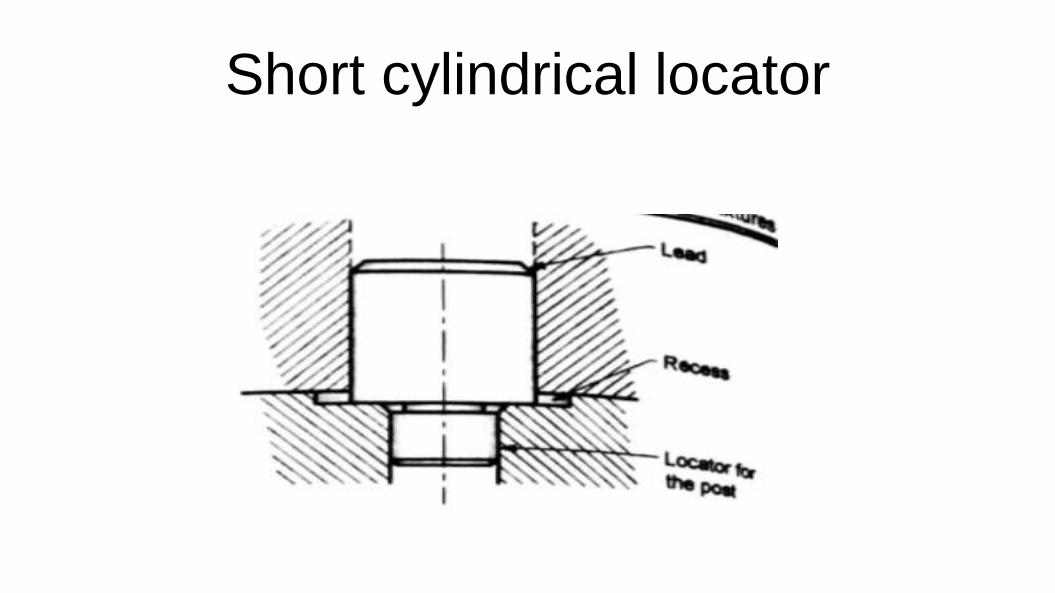
Short cylindrical locator
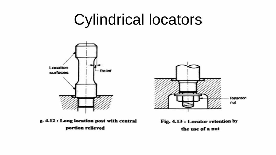
Cylindrical locators
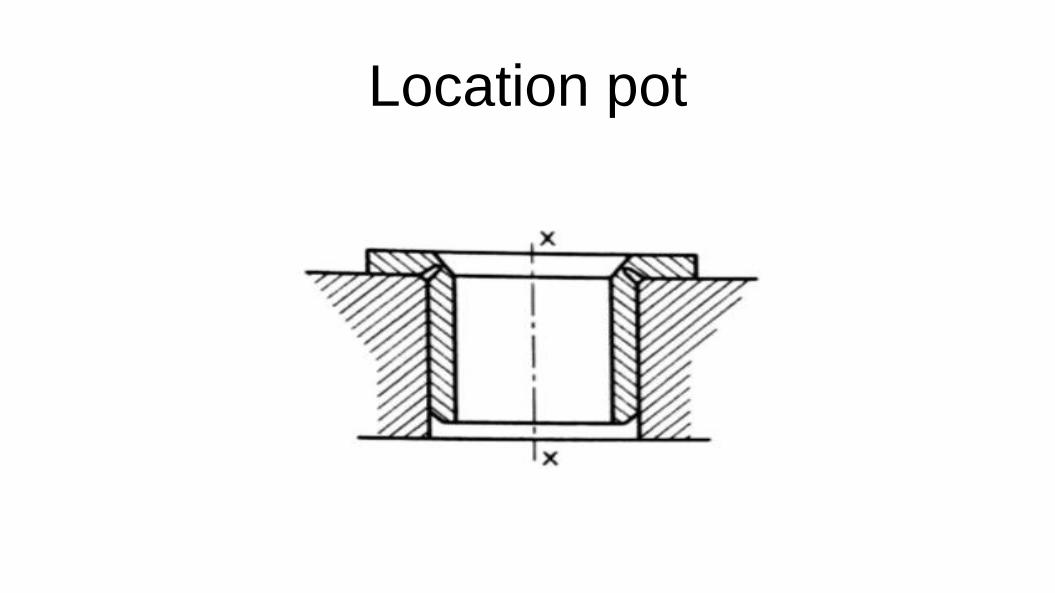
Location pot

Conical locators
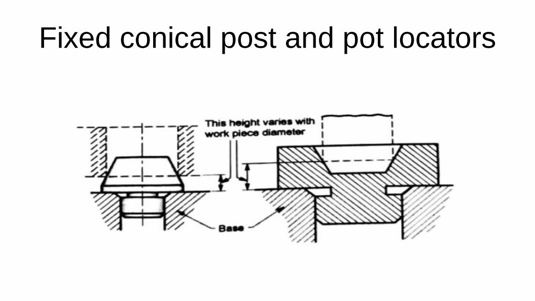
Fixed conical post and pot locators
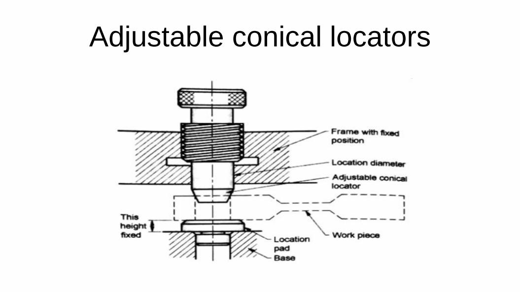
Adjustable conical locators
Drill Bushes & JigsProf. Kunalsinh Kathia
Mechanical Engineering Department
HJD INSTITUTE KERA
Prof. Kunalsinh Kathia (HJDITER)
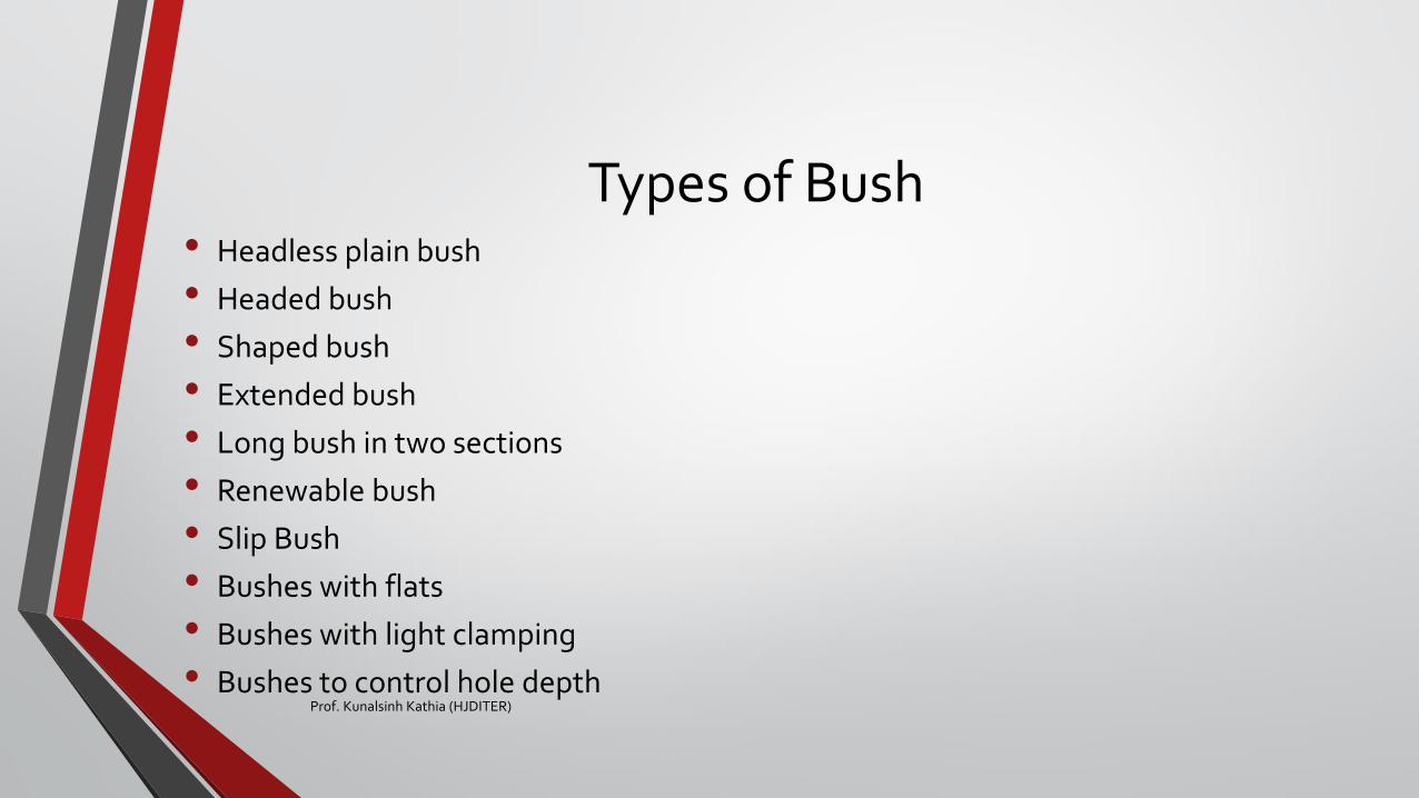
Types of Bush• Headless plain bush
• Headed bush
• Shaped bush
• Extended bush
• Long bush in two sections
• Renewable bush
• Slip Bush
• Bushes with flats
• Bushes with light clamping
• Bushes to control hole depthProf. Kunalsinh Kathia (HJDITER)

Headless plain bush
Prof. Kunalsinh Kathia (HJDITER)
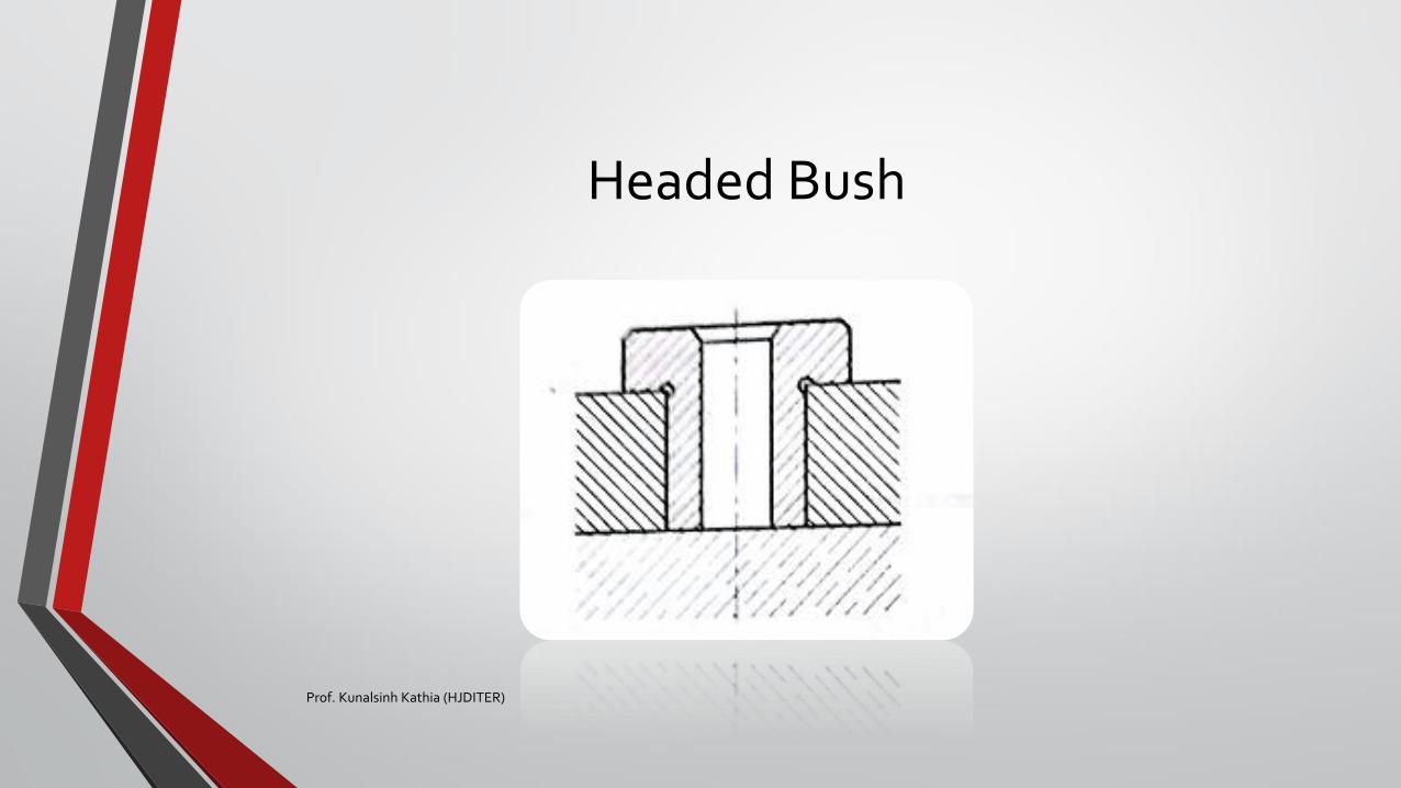
Headed Bush
Prof. Kunalsinh Kathia (HJDITER)
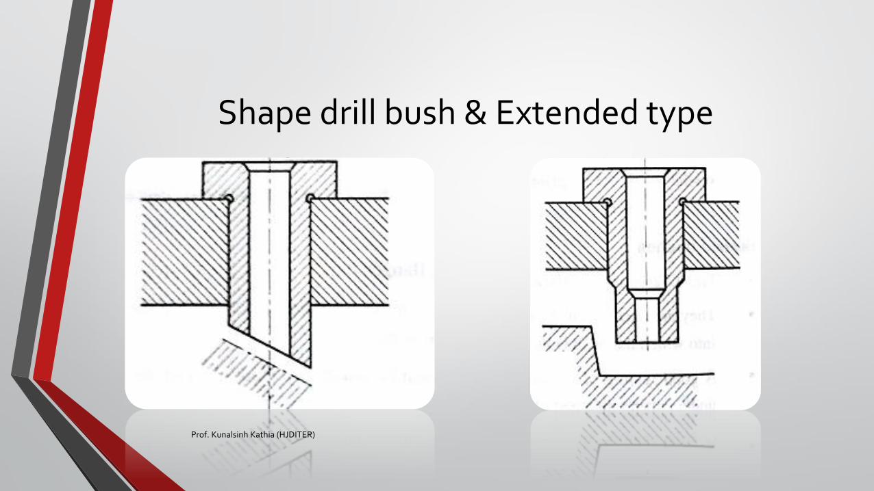
Shape drill bush & Extended type
Prof. Kunalsinh Kathia (HJDITER)
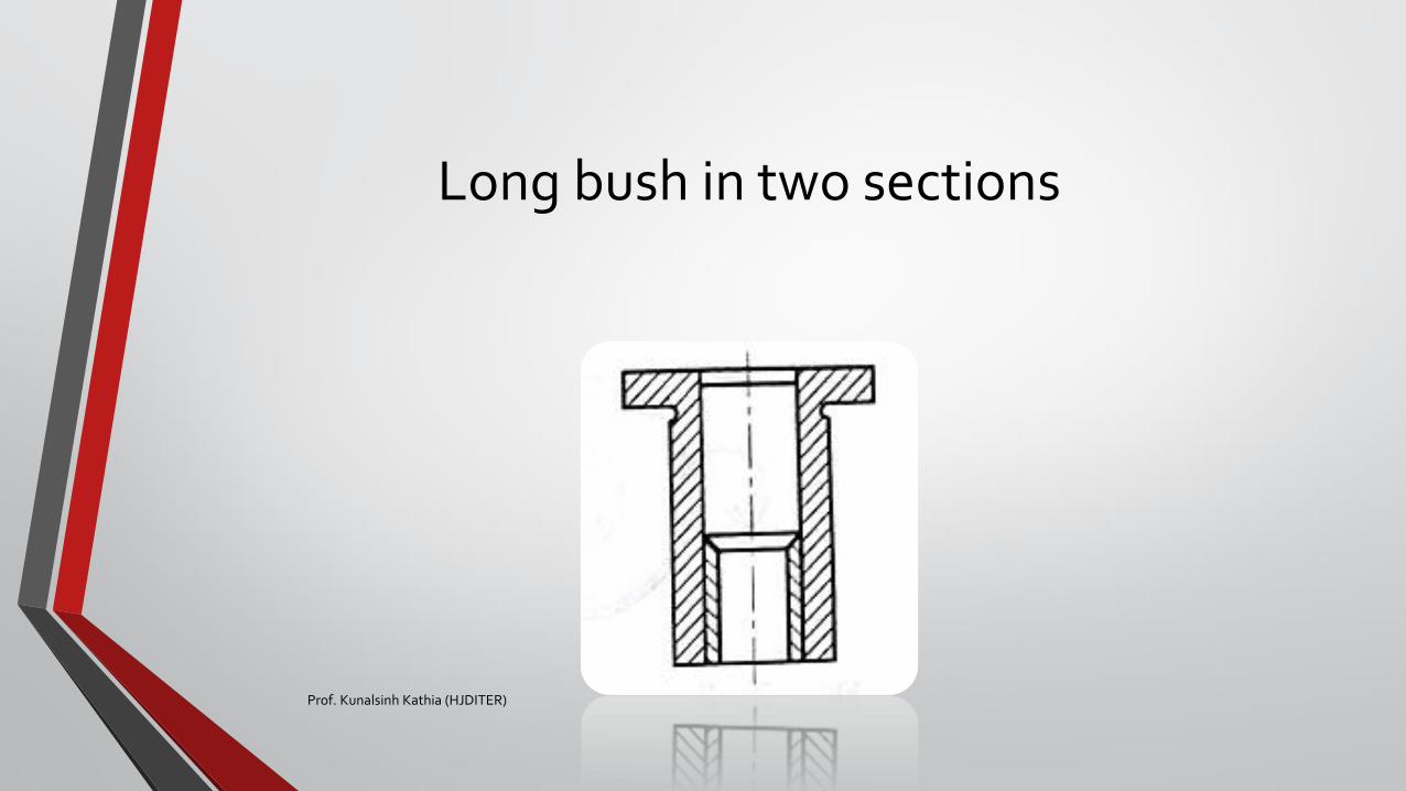
Long bush in two sections
Prof. Kunalsinh Kathia (HJDITER)
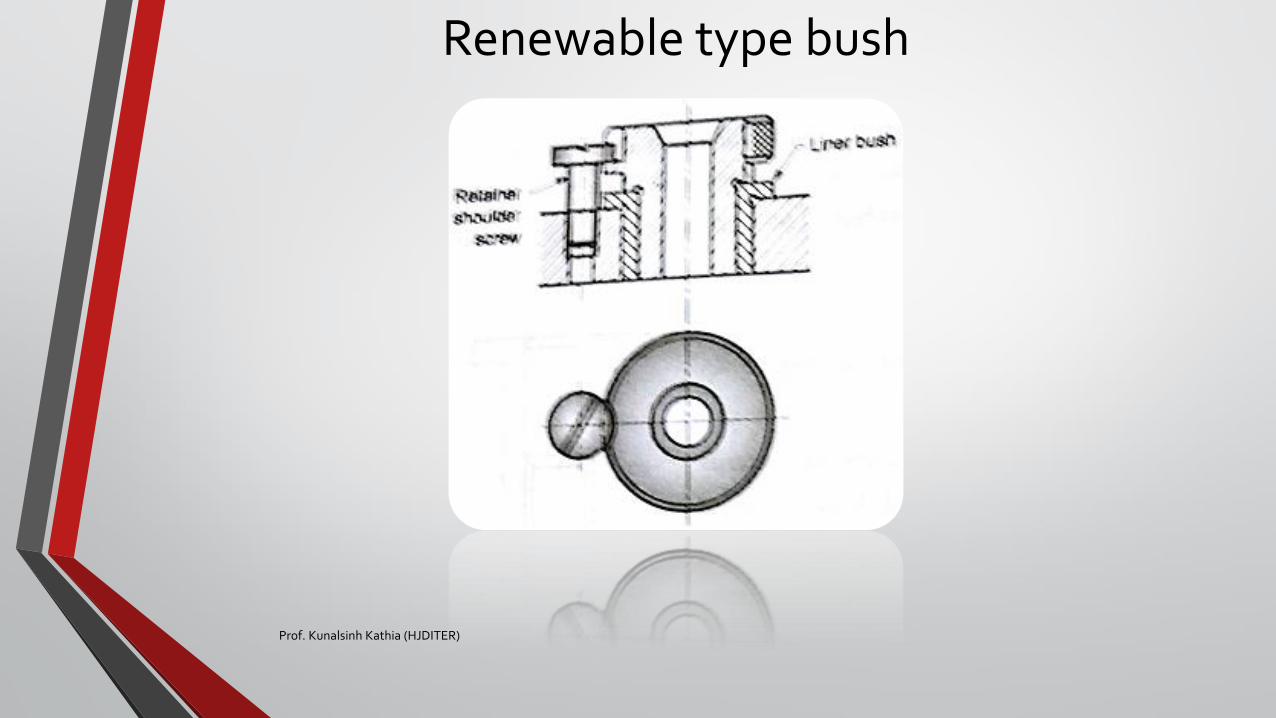
Renewable type bush
Prof. Kunalsinh Kathia (HJDITER)
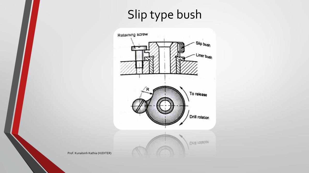
Slip type bush
Prof. Kunalsinh Kathia (HJDITER)
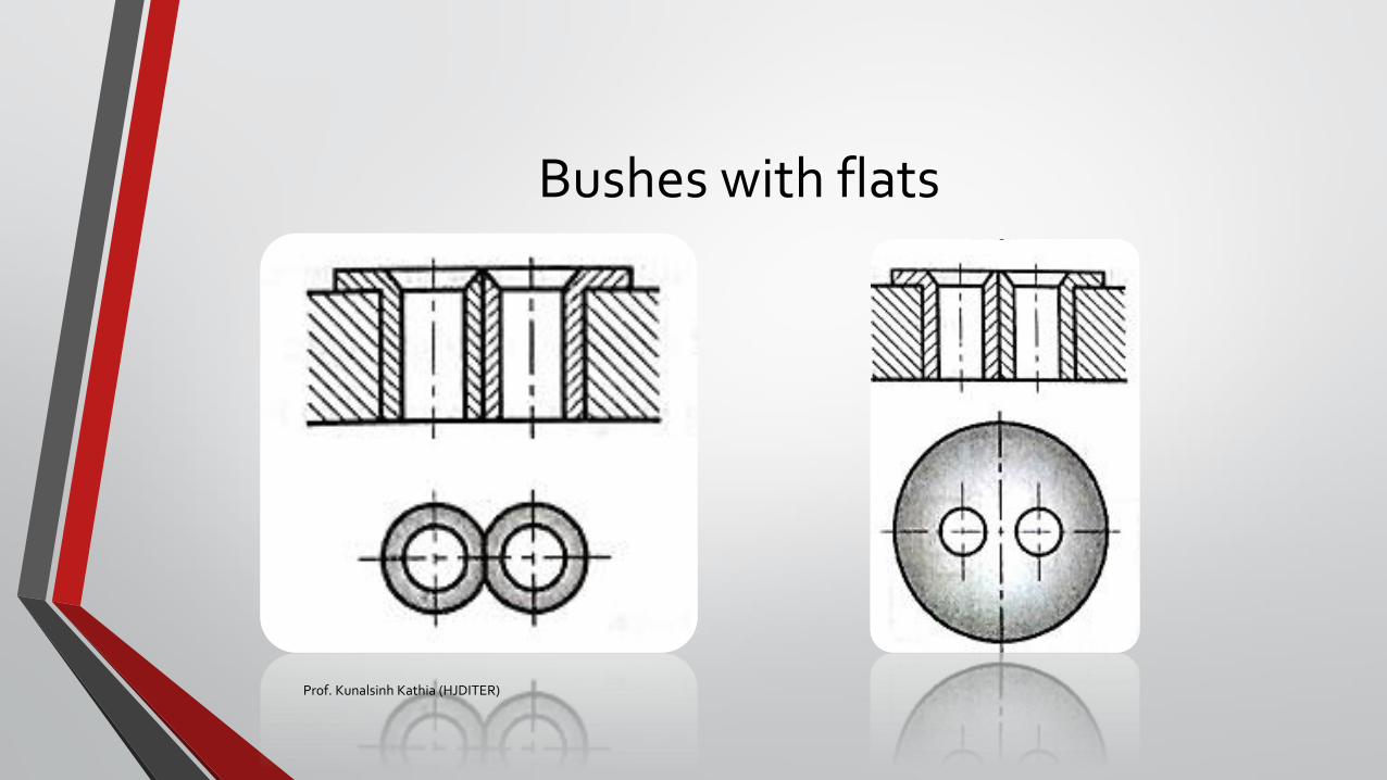
Bushes with flats
Prof. Kunalsinh Kathia (HJDITER)
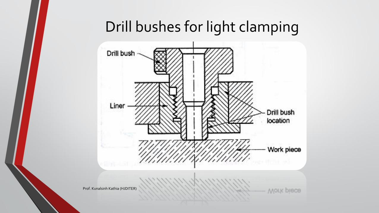
Drill bushes for light clamping
Prof. Kunalsinh Kathia (HJDITER)
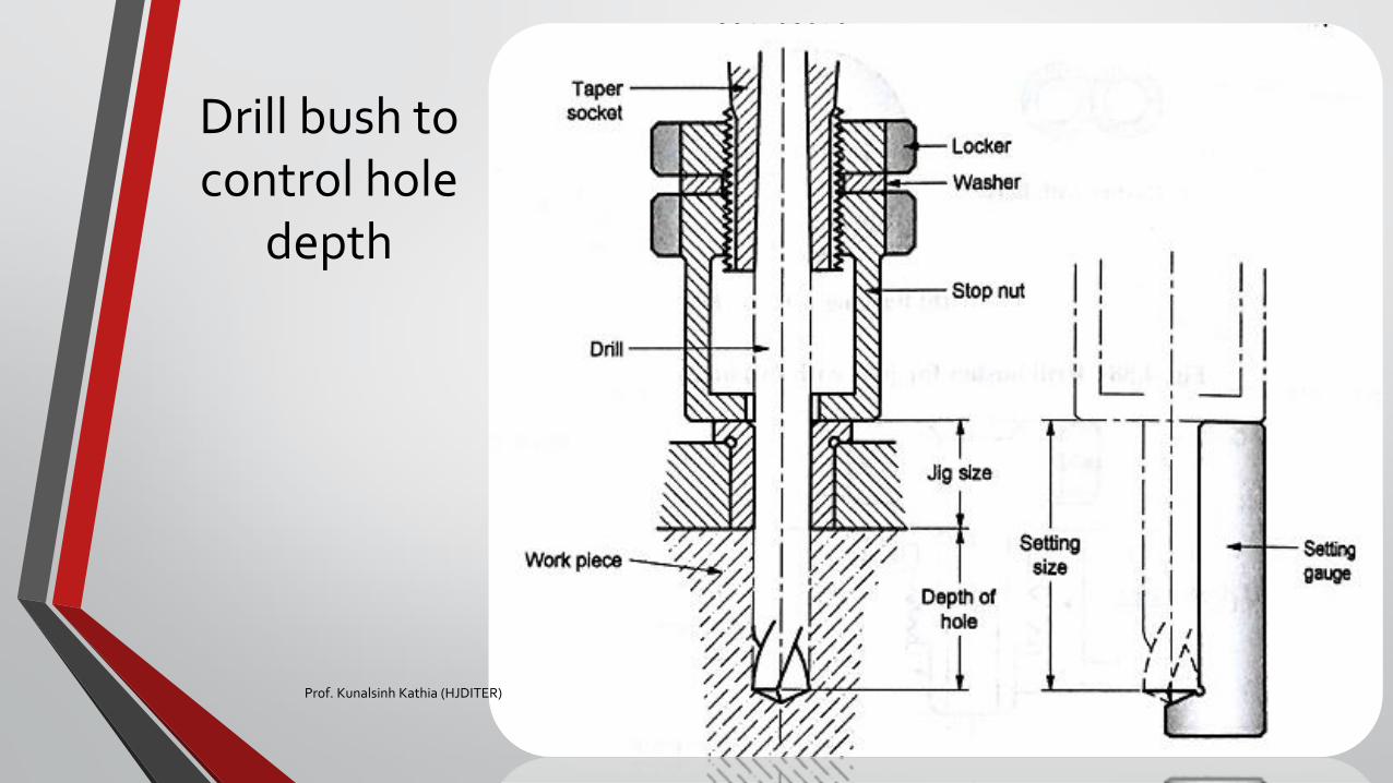
Drill bush to control hole
depth
Prof. Kunalsinh Kathia (HJDITER)
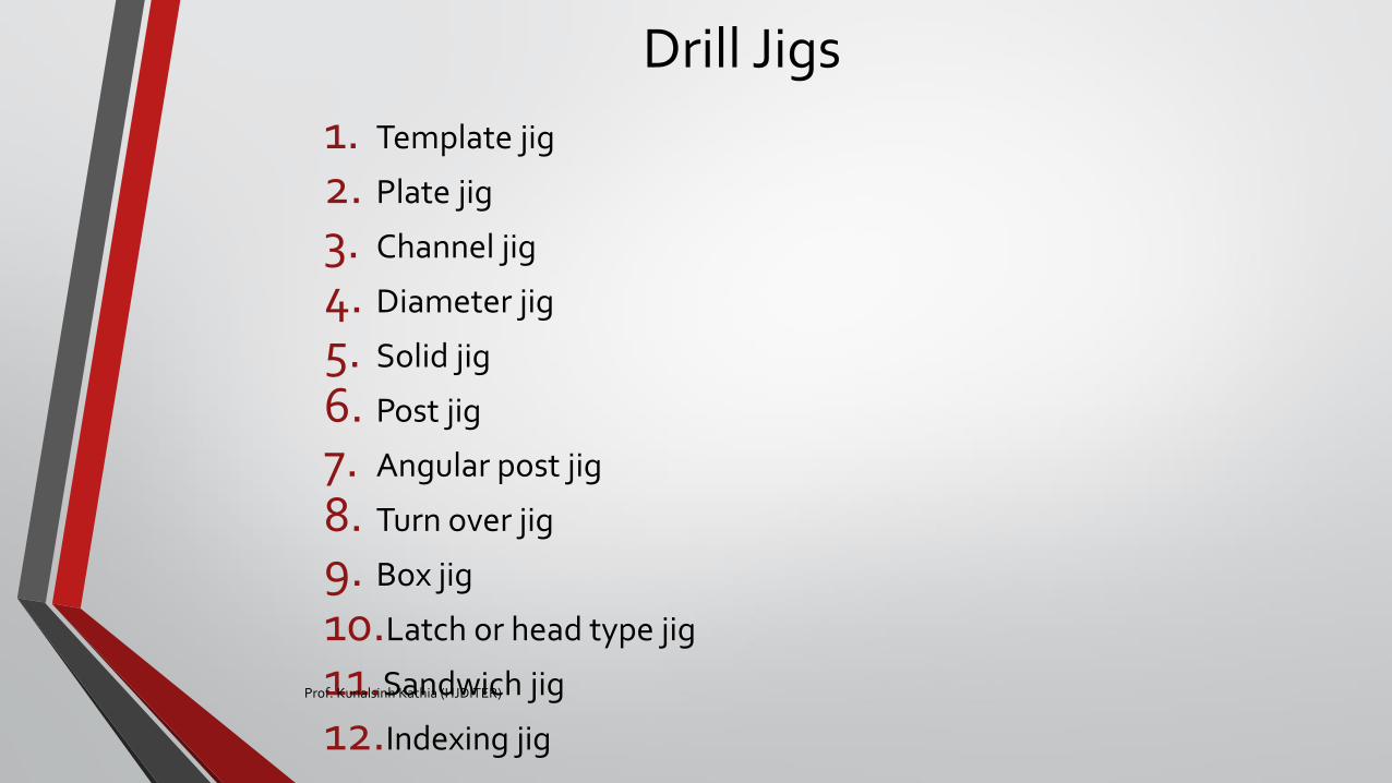
Drill Jigs
1. Template jig
2. Plate jig
3. Channel jig
4. Diameter jig
5. Solid jig
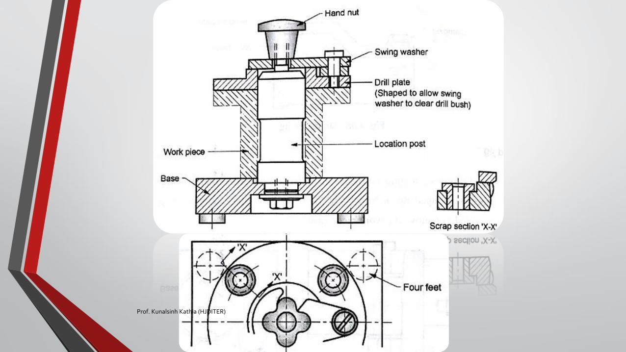
6. Post jig
7. Angular post jig
8. Turn over jig
9. Box jig
10.Latch or head type jig
11.Sandwich jig
12.Indexing jig
Prof. Kunalsinh Kathia (HJDITER)
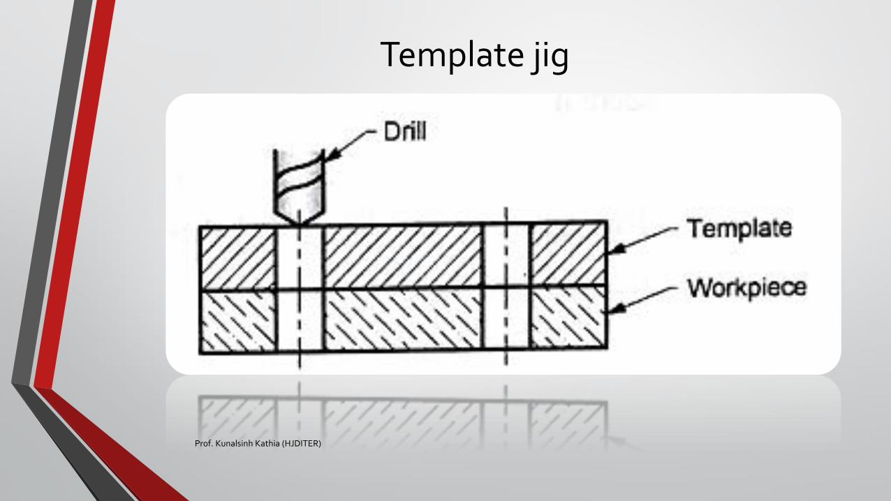
Template jig
Prof. Kunalsinh Kathia (HJDITER)
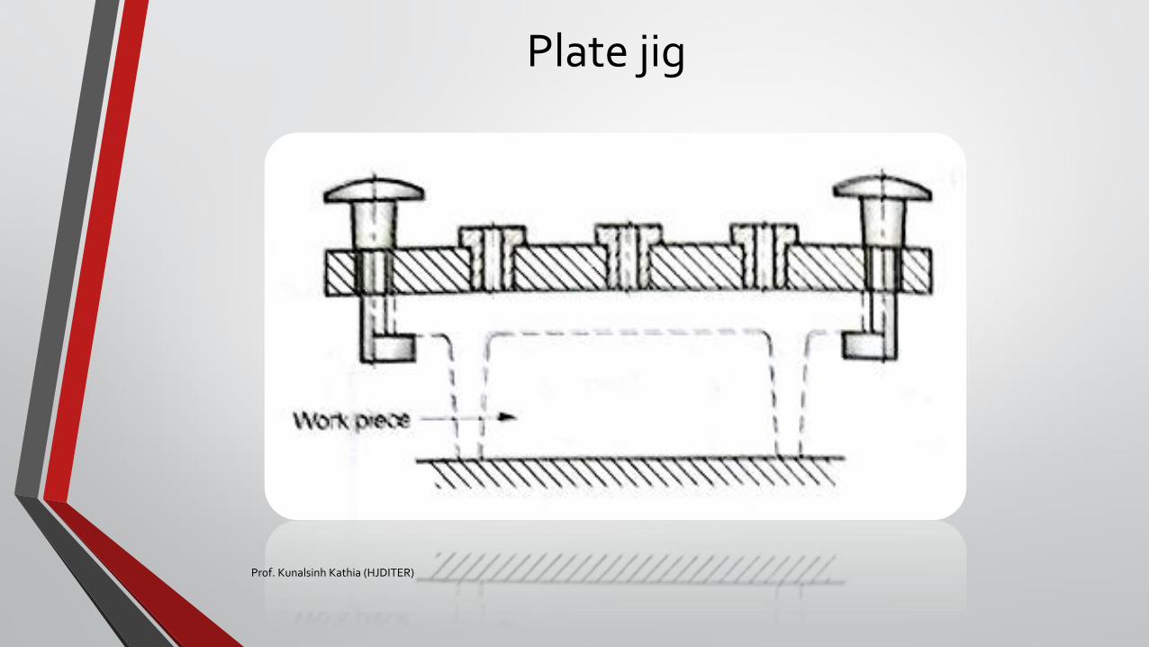
Plate jig
Prof. Kunalsinh Kathia (HJDITER)
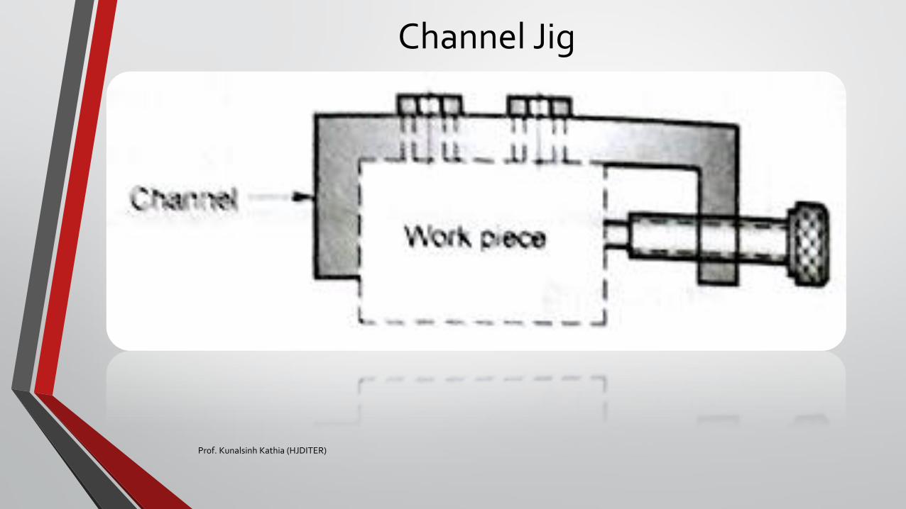
Channel Jig
Prof. Kunalsinh Kathia (HJDITER)
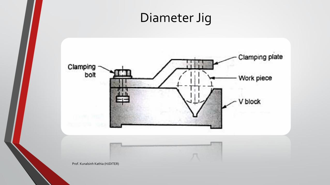
Diameter Jig
Prof. Kunalsinh Kathia (HJDITER)
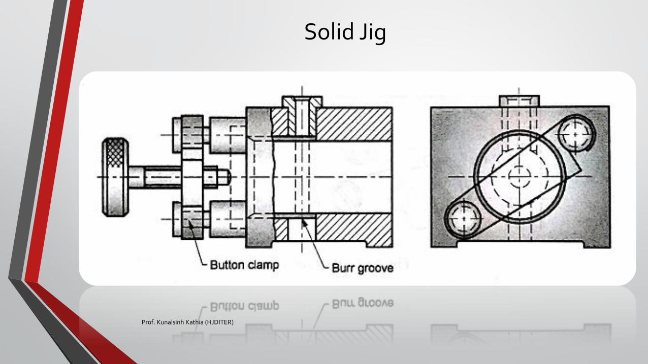
Solid Jig
Prof. Kunalsinh Kathia (HJDITER)

Post Jig
Prof. Kunalsinh Kathia (HJDITER)
Prof. Kunalsinh Kathia (HJDITER)
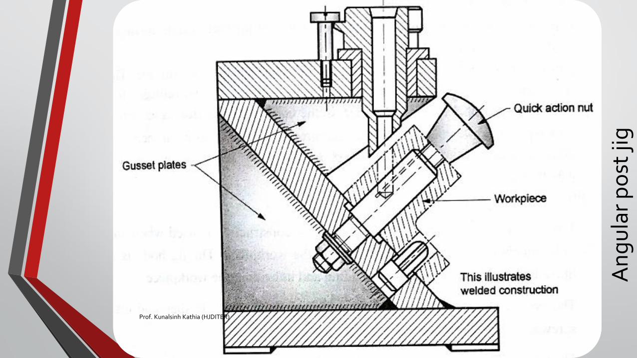
An
gu
lar
po
st ji
g
Prof. Kunalsinh Kathia (HJDITER)
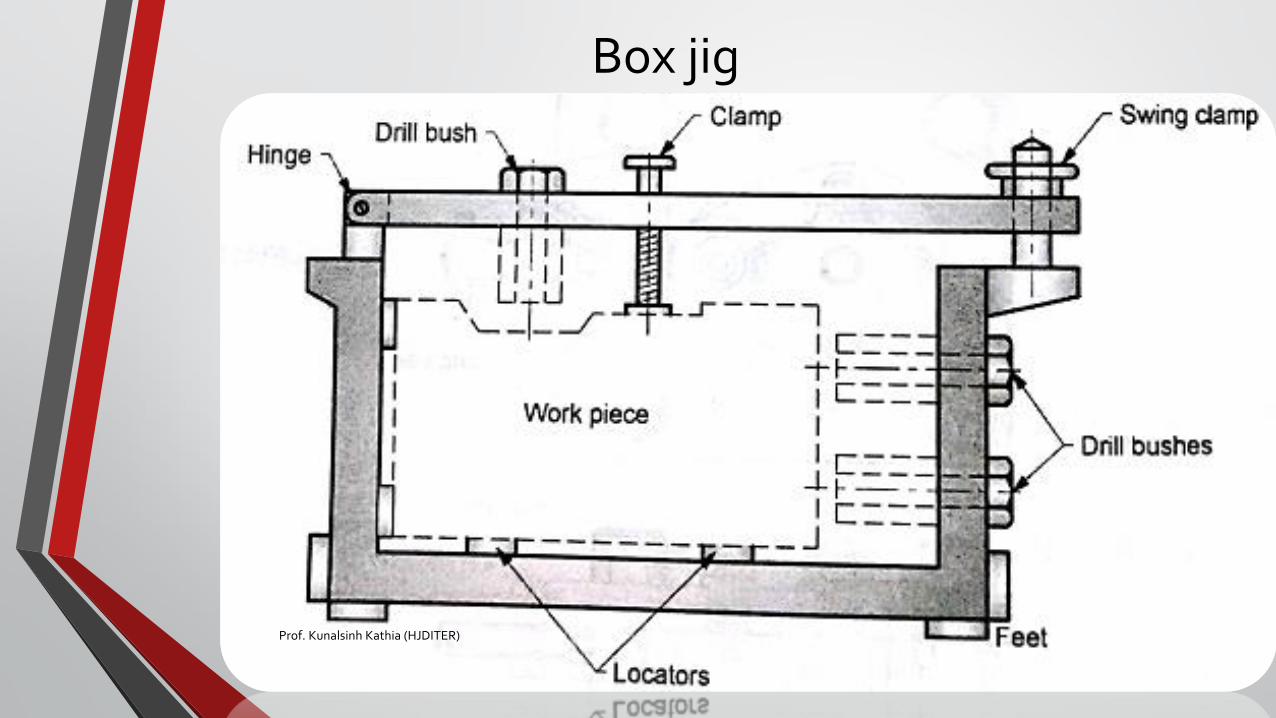
Box jig
Prof. Kunalsinh Kathia (HJDITER)
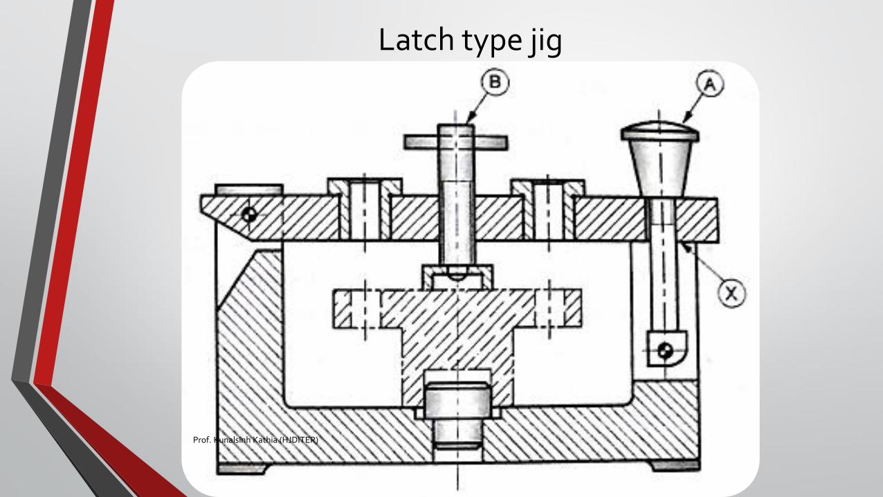
Latch type jig
Prof. Kunalsinh Kathia (HJDITER)

Indexing jig
Prof. Kunalsinh Kathia (HJDITER)

Presses (Punch & Die)PROF. KUNALSINH KATHIA
PRODUCTION TECHNOLOGY
PROF. KUNALSINH KATHIA (HJDITER)
Common cutting operationsBlanking
Punching or piercing
Trimming
Shaving
Notching
Lancing
Nibbing
Perforating
Parting
Shearing
PROF. KUNALSINH KATHIA (HJDITER)
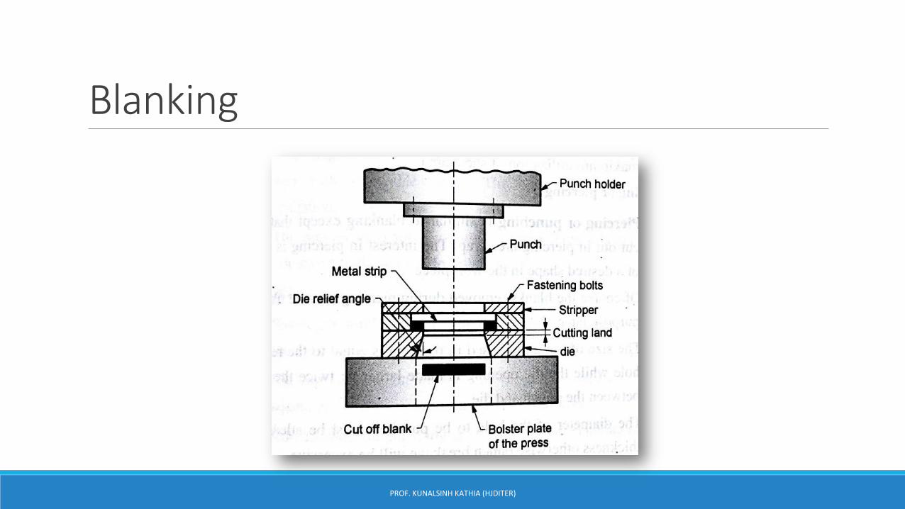
Blanking
PROF. KUNALSINH KATHIA (HJDITER)
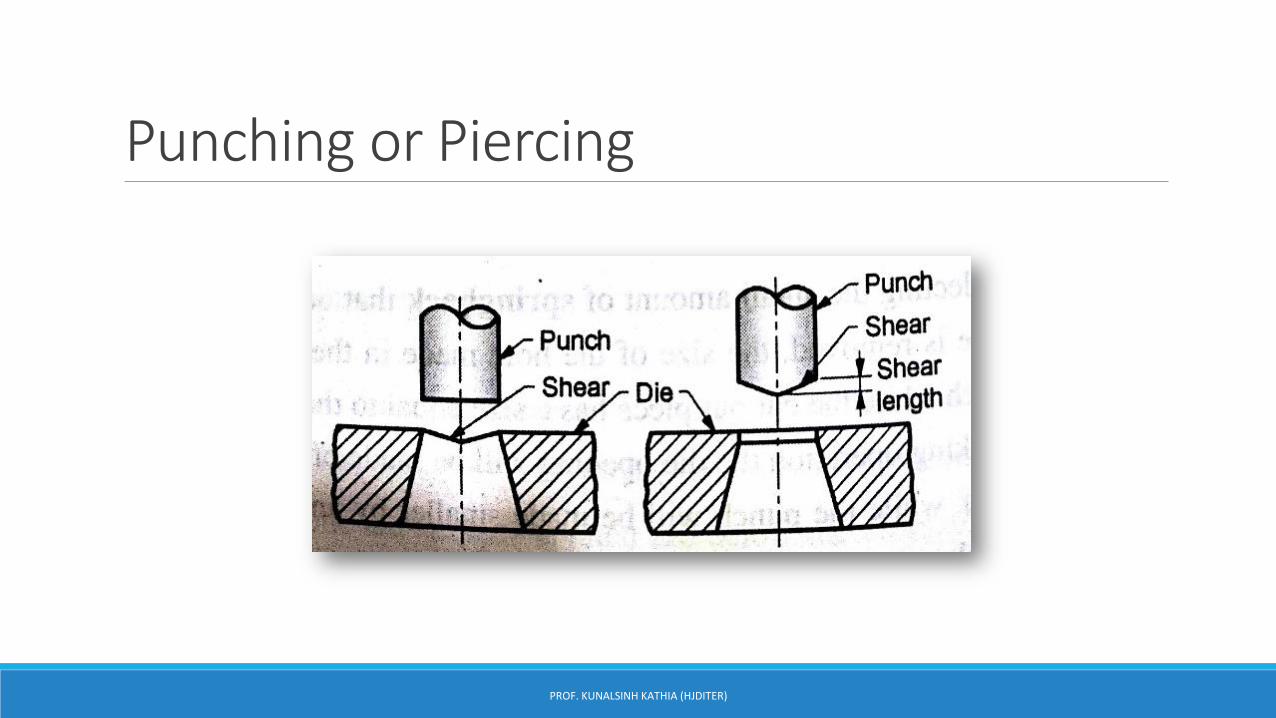
Punching or Piercing
PROF. KUNALSINH KATHIA (HJDITER)

Trimming
Is process to remove excessive material.
PROF. KUNALSINH KATHIA (HJDITER)
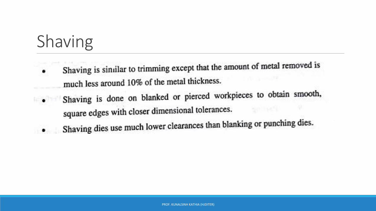
Shaving
PROF. KUNALSINH KATHIA (HJDITER)

Notching
PROF. KUNALSINH KATHIA (HJDITER)
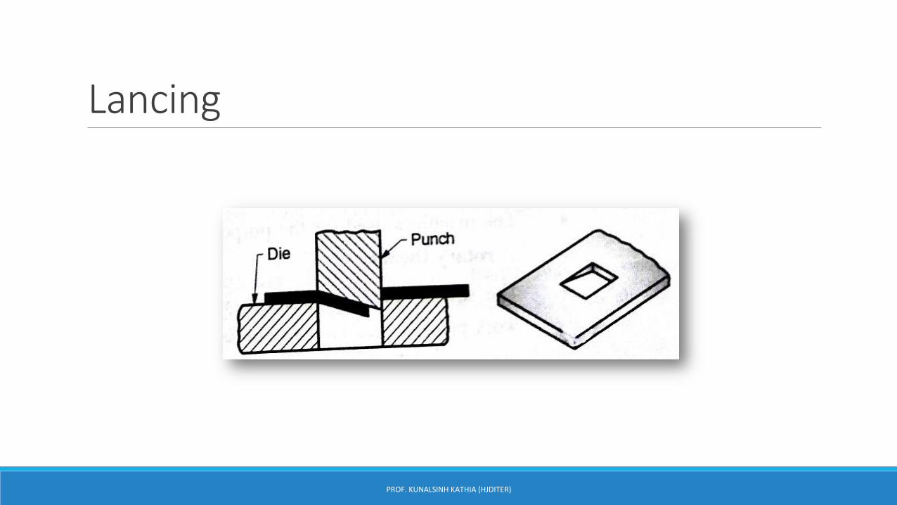
Lancing
PROF. KUNALSINH KATHIA (HJDITER)
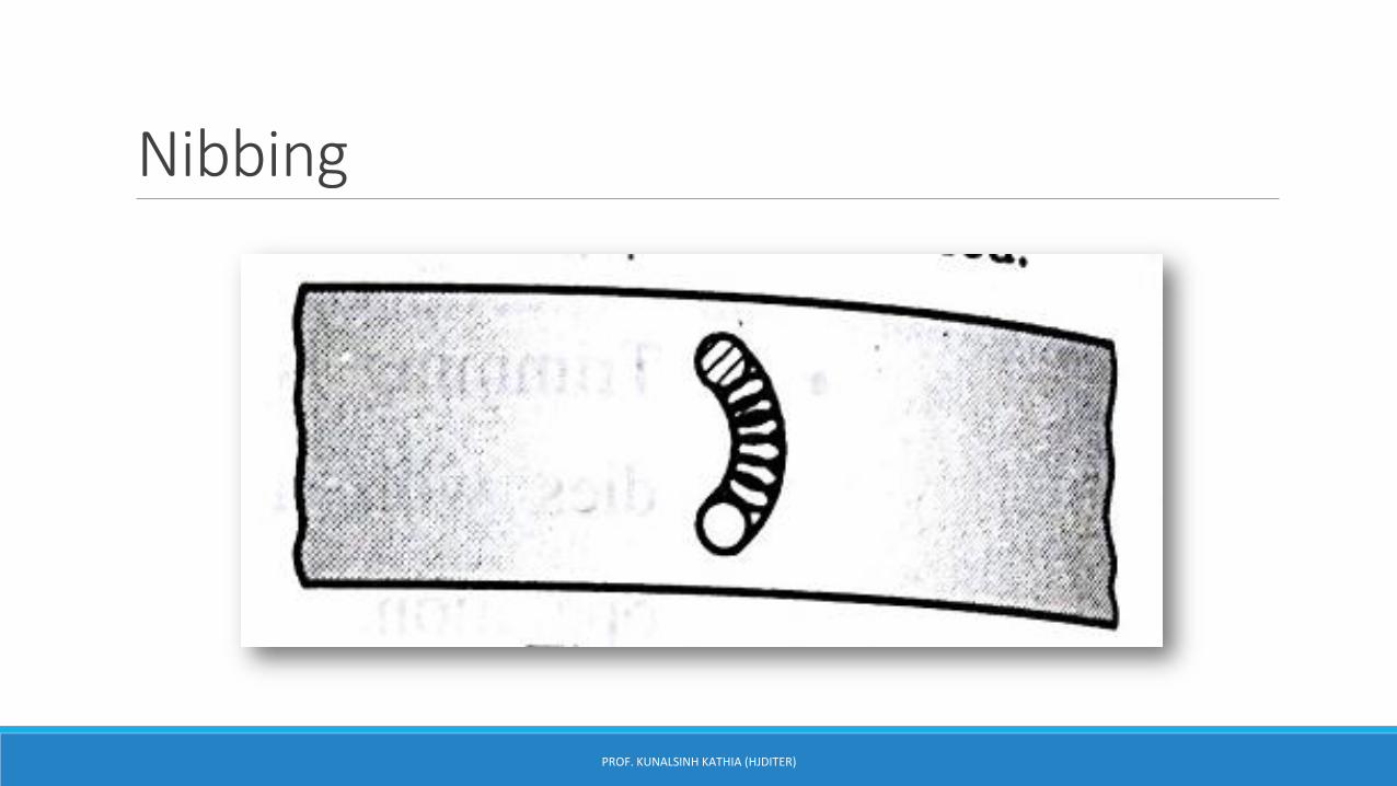
Nibbing
PROF. KUNALSINH KATHIA (HJDITER)
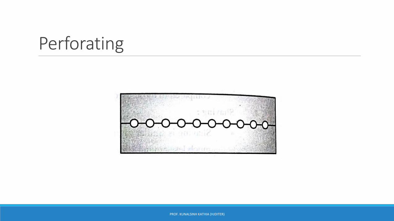
Perforating
PROF. KUNALSINH KATHIA (HJDITER)
Parting
PROF. KUNALSINH KATHIA (HJDITER)
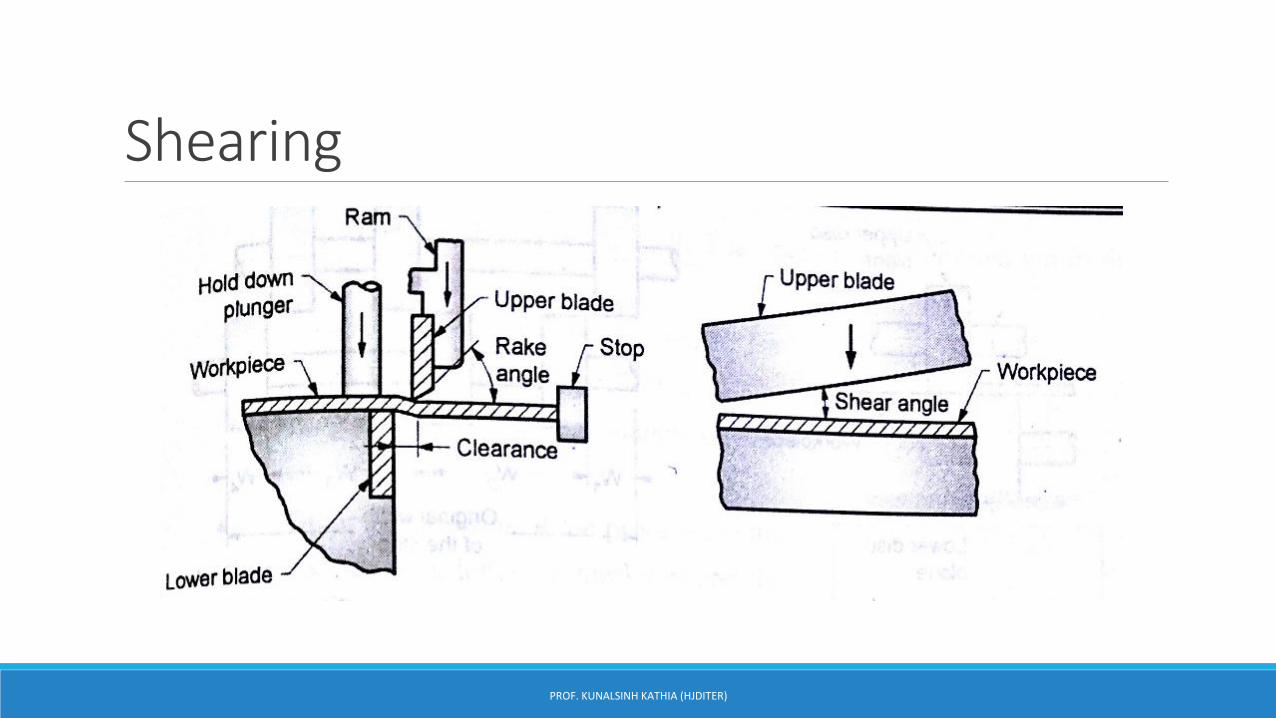
Shearing
PROF. KUNALSINH KATHIA (HJDITER)
Forming operations1. Bending
2. Drawing
3. Rigid die operations like buldging, curling,coining etc
4. Flexible die operation like Rubber pad forming, marforming, hydroforming
PROF. KUNALSINH KATHIA (HJDITER)
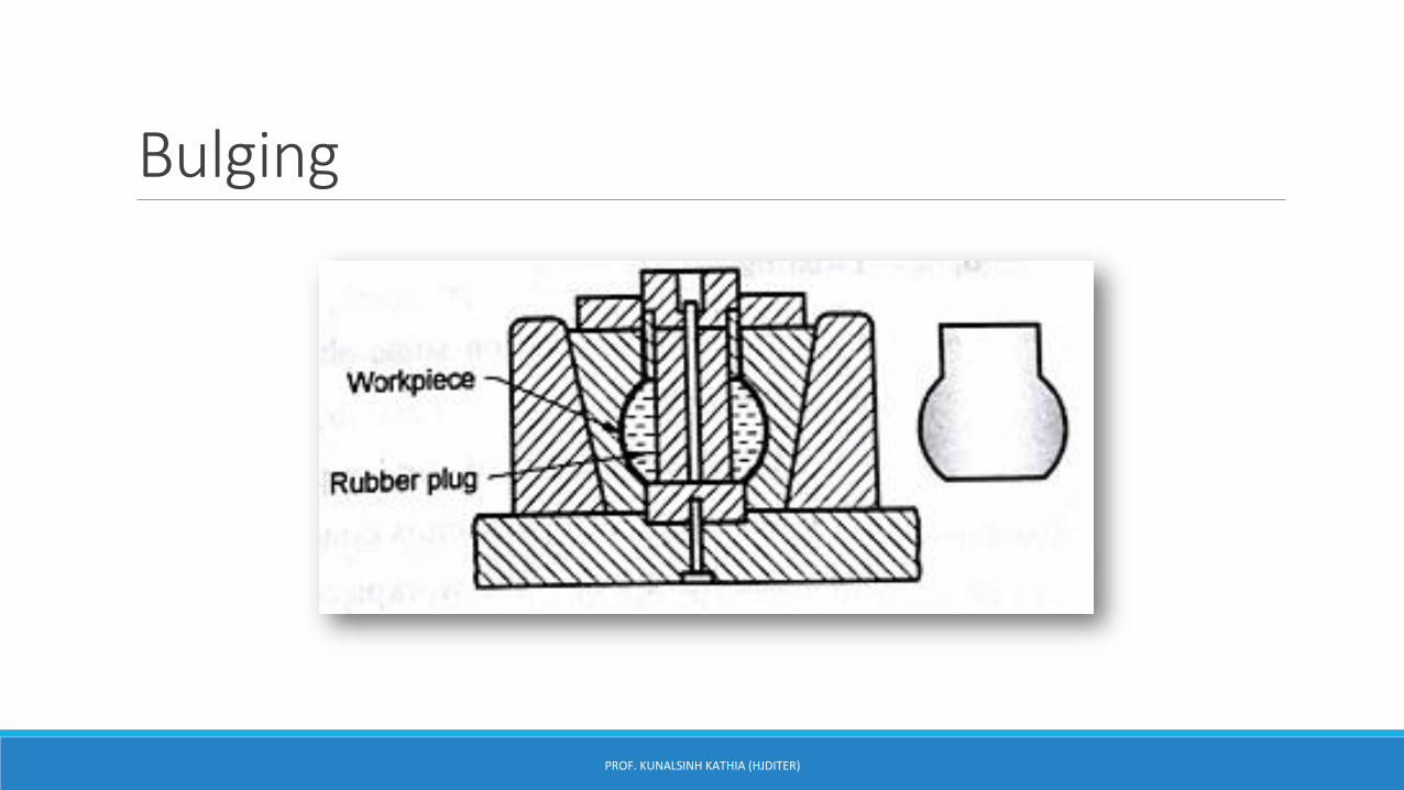
Bulging
PROF. KUNALSINH KATHIA (HJDITER)
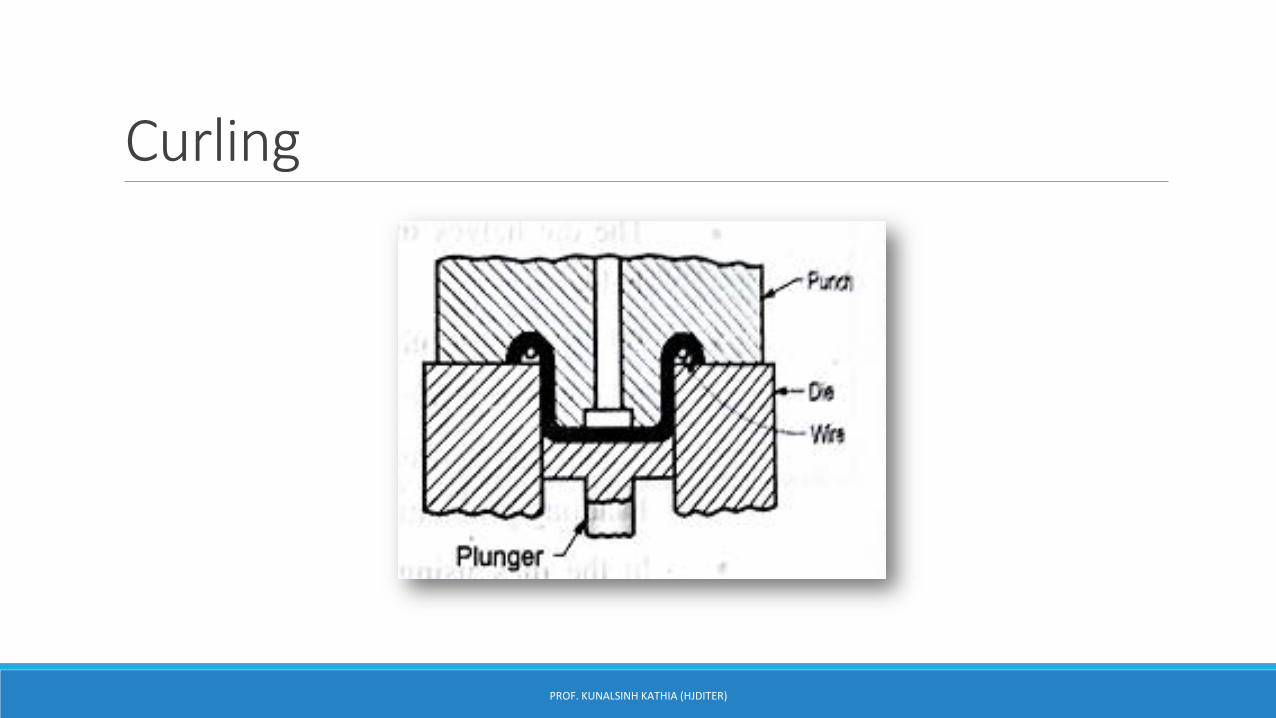
Curling
PROF. KUNALSINH KATHIA (HJDITER)
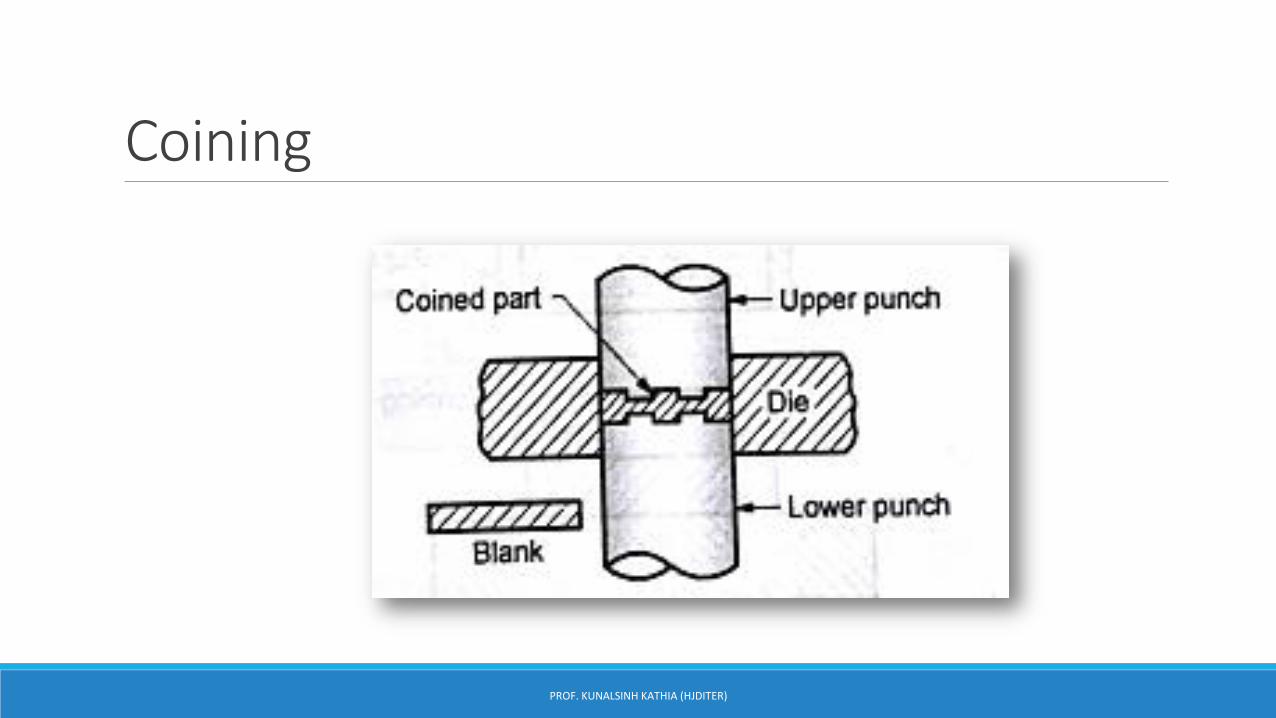
Coining
PROF. KUNALSINH KATHIA (HJDITER)
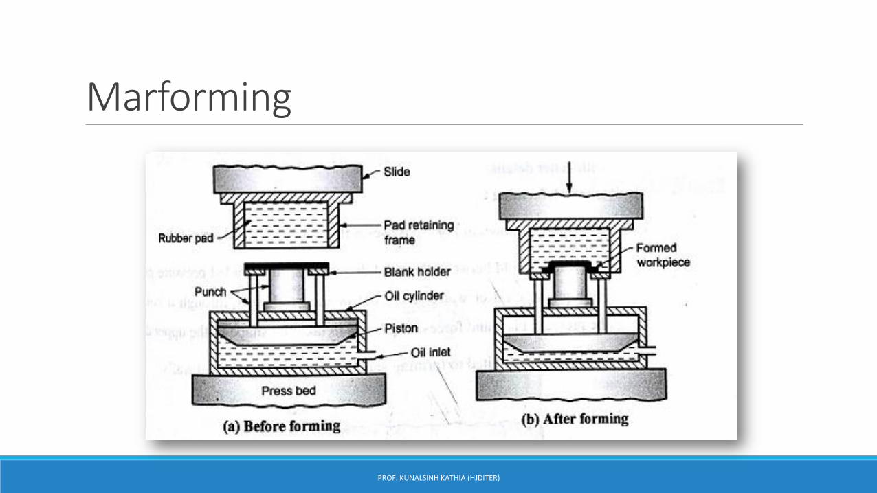
Marforming
PROF. KUNALSINH KATHIA (HJDITER)
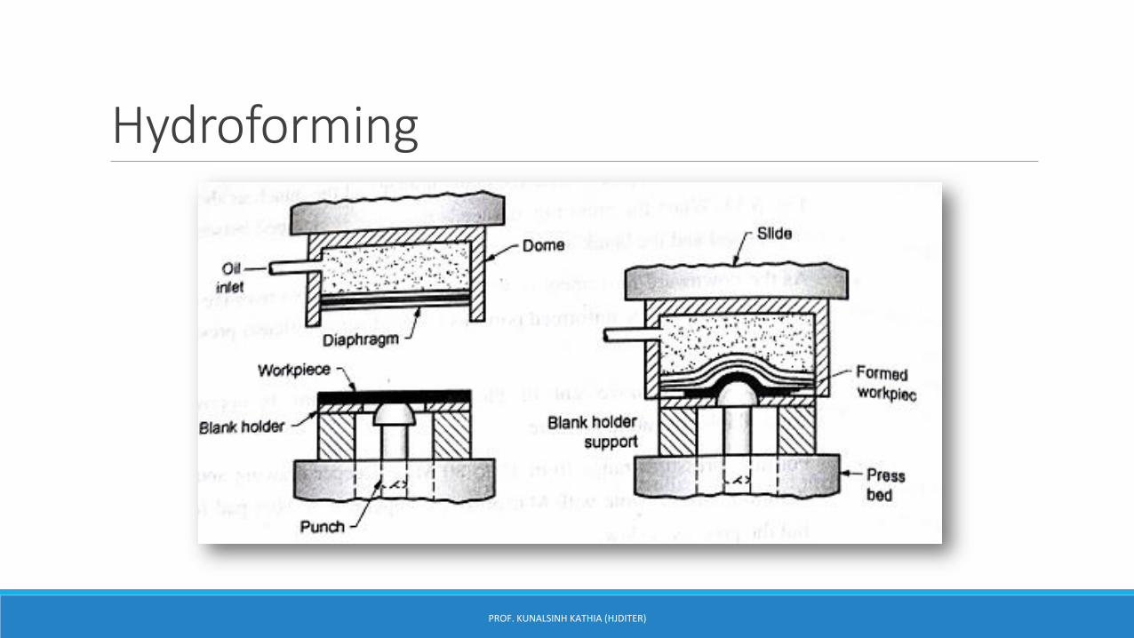
Hydroforming
PROF. KUNALSINH KATHIA (HJDITER)
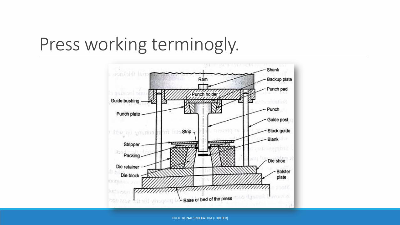
Press working terminogly.
PROF. KUNALSINH KATHIA (HJDITER)
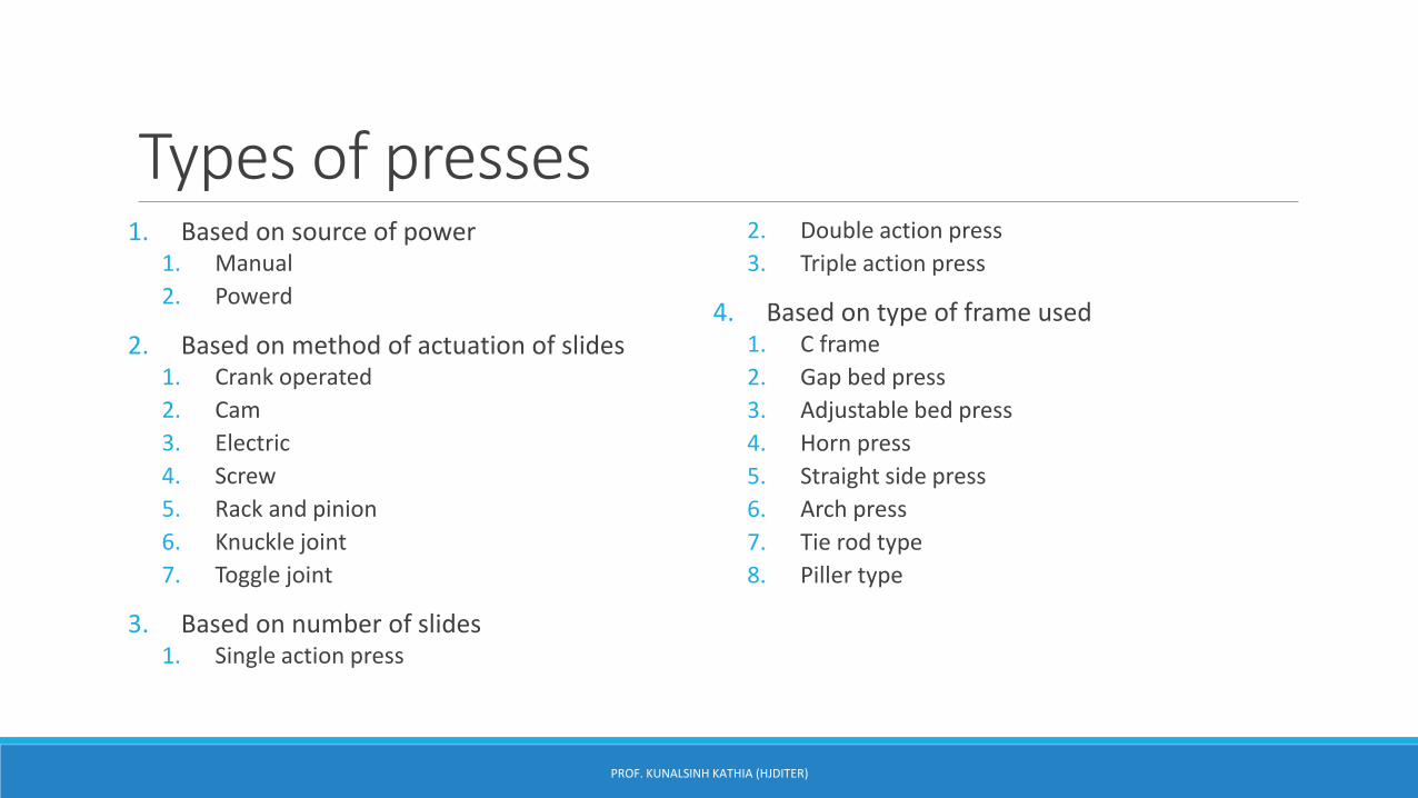
Types of presses1. Based on source of power
1. Manual
2. Powerd
2. Based on method of actuation of slides1. Crank operated
2. Cam
3. Electric
4. Screw
5. Rack and pinion
6. Knuckle joint
7. Toggle joint
3. Based on number of slides1. Single action press
2. Double action press
3. Triple action press
4. Based on type of frame used1. C frame
2. Gap bed press
3. Adjustable bed press
4. Horn press
5. Straight side press
6. Arch press
7. Tie rod type
8. Piller type
PROF. KUNALSINH KATHIA (HJDITER)
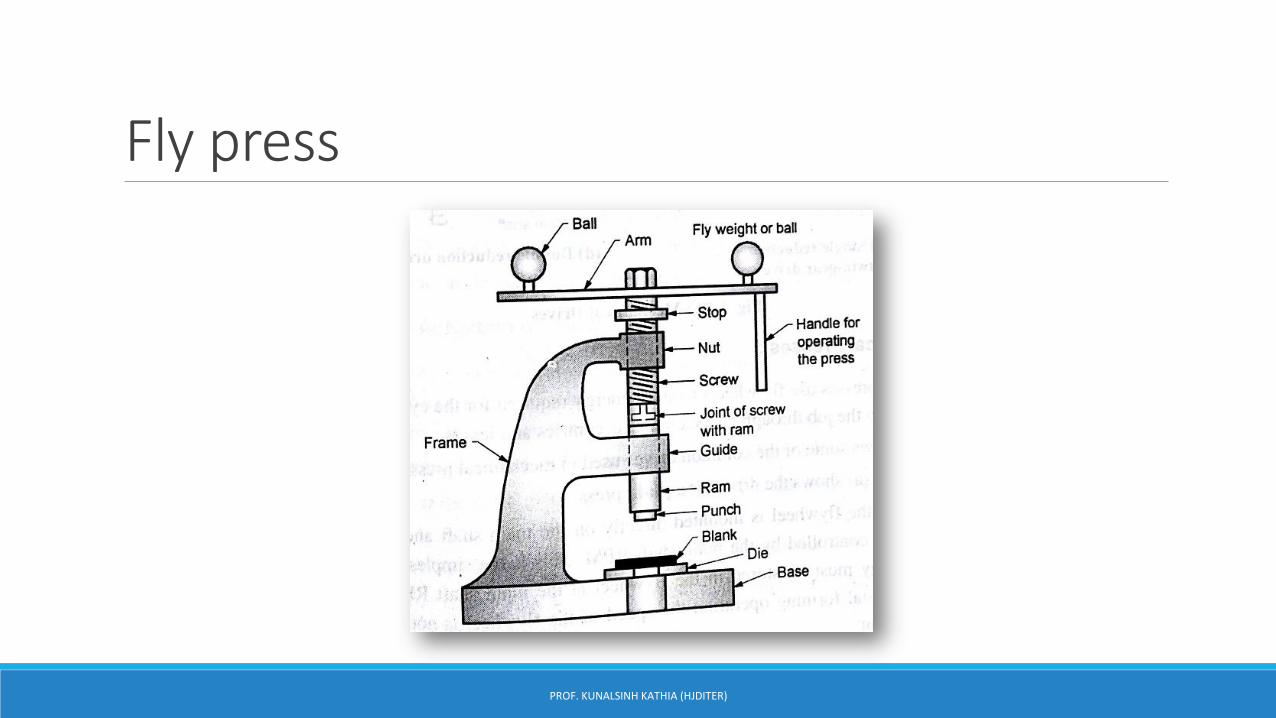
Fly press
PROF. KUNALSINH KATHIA (HJDITER)
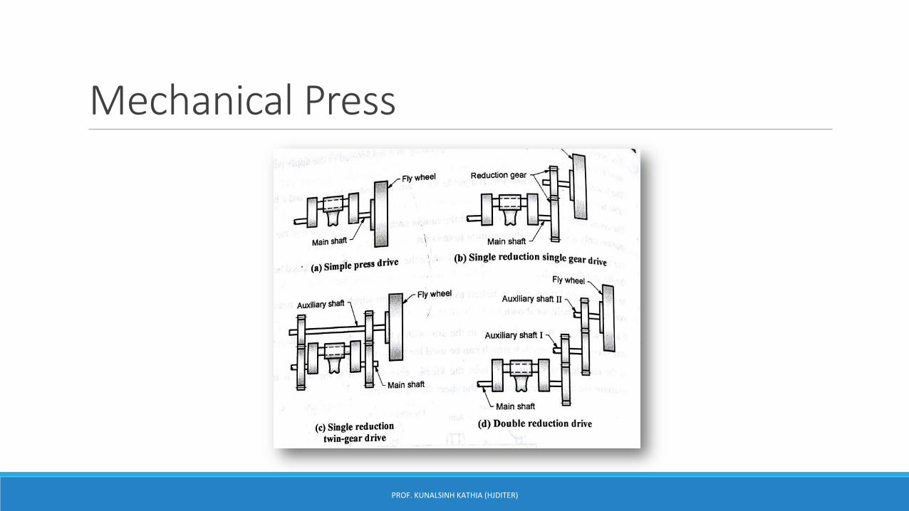
Mechanical Press
PROF. KUNALSINH KATHIA (HJDITER)
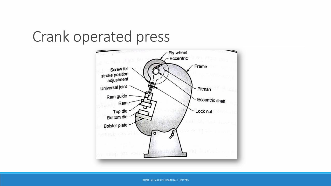
Crank operated press
PROF. KUNALSINH KATHIA (HJDITER)
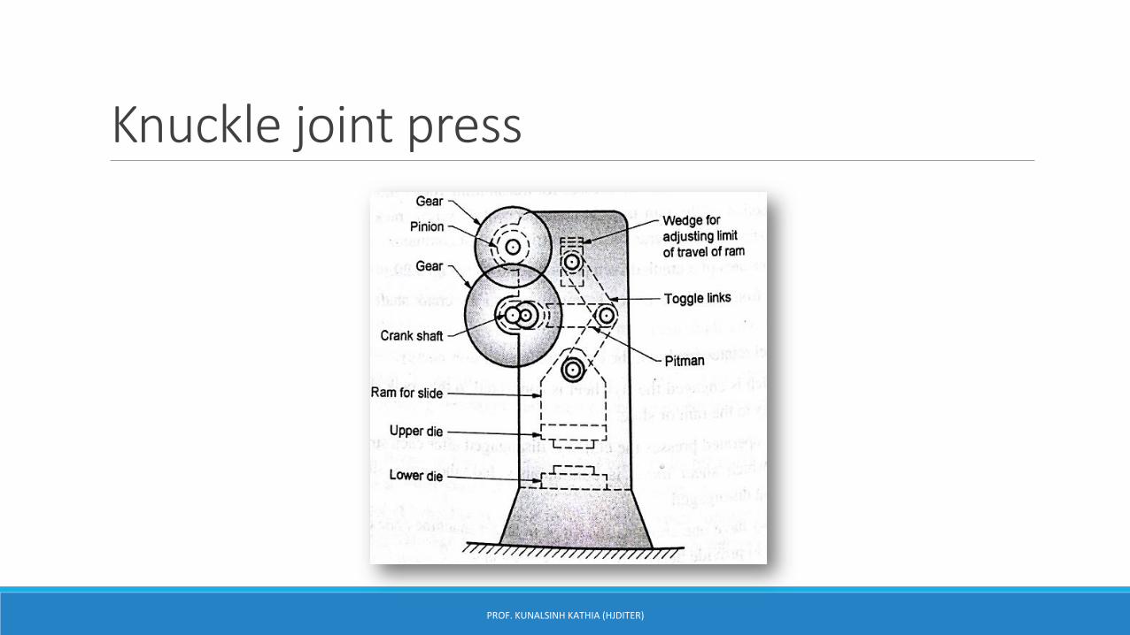
Knuckle joint press
PROF. KUNALSINH KATHIA (HJDITER)
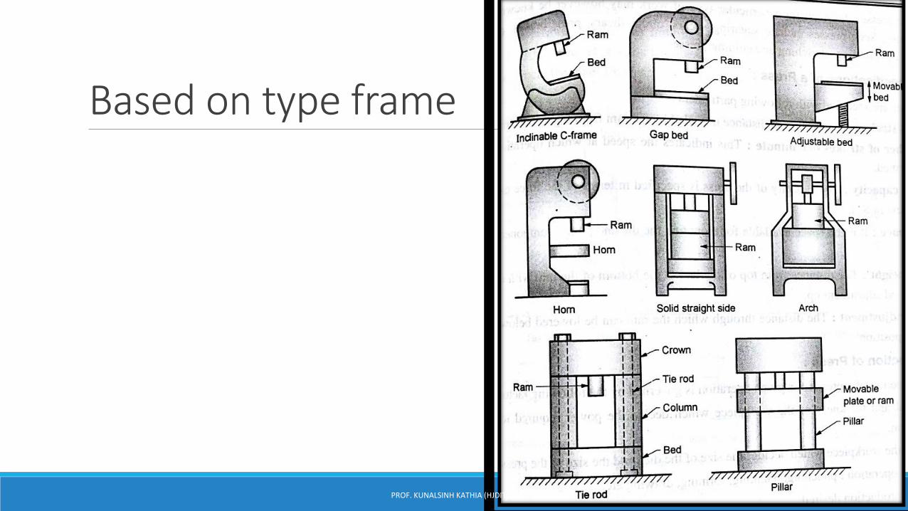
Based on type frame
PROF. KUNALSINH KATHIA (HJDITER)

AJM
Production technology
Prof. Kunalsinh Kathia
HJD INSTITUTE

DEFINATION:-
In Abrasive Jet Machining (AJM), abrasive
particles are made to impinge on the work
material at a high velocity. The jet of
abrasive particles is carried by carrier gas
or air.
The high velocity stream of abrasive is
generated by converting the pressure
energy of the carrier gas or air to its kinetic
energy and hence high velocity jet.
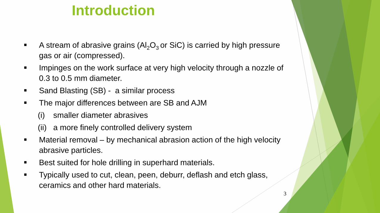
Introduction
3
A stream of abrasive grains (Al2O3 or SiC) is carried by high pressure
gas or air (compressed).
Impinges on the work surface at very high velocity through a nozzle of
0.3 to 0.5 mm diameter.
Sand Blasting (SB) - a similar process
The major differences between are SB and AJM
(i) smaller diameter abrasives
(ii) a more finely controlled delivery system
Material removal – by mechanical abrasion action of the high velocity
abrasive particles.
Best suited for hole drilling in superhard materials.
Typically used to cut, clean, peen, deburr, deflash and etch glass,
ceramics and other hard materials.
4
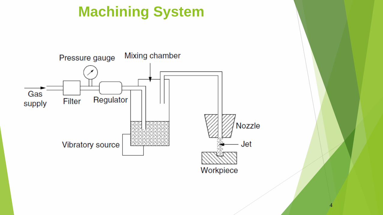
Machining System
5
A gas (Nitrogen, CO2 or air) is supplied at 2 – 8 kg/cm2
Oxygen should never be used. (because, it causes violent
chemical action with the workpiece chips or abrasive particles).
Gas passes through a mixing chamber after filtration and
regulation.
In the mixing chamber, abrasive particles (10 – 40 m) are present
and vibrated at 50 Hz.
Amplitude of vibration – to control the feed rate of abrasives.
(Gas + abrasives) - passed through a 0.45 mm diameter tungsten
carbide nozzle at a speed of 150 – 300 m/s.
The nozzle is directed over the area to be machined.
Machining System – Contd.
6
Aluminum oxide (Al2O3) and silicon carbide (SiC) powders are
used for heavy cleaning, cutting and deburring.
Magnesium carbonate is recommended for use in light cleaning
and etching.
Sodium bicarbonate – fine cleaning and cutting of soft materials.
Commercial grade powders are not suitable – b’cos their sizes are
not well classified. Also, they may contain silica which can cause a
health hazard.
Abrasive powders are not reused. B’cos, contaminations and worn
grits will reduce the machining rate (MRR).
The nozzle stand off distance is 0.81 mm.
Machining System – Contd.
7
Relative motion between nozzle and workpiece – can be manual
Or automatically controlled using cam drives, tracer mechanisms
or using computer controlled according to the cut geometry
required.
Masks of copper, glass or rubber – can be used to concentrate the
jet stream of abrasives to a confined area on the workpiece.
Intricate and precise shapes can be produced using masks with
corresponding contours.
Dust removal or collecting equipment must be incorporated to
protect the environment.
Machining System – Contd.
8
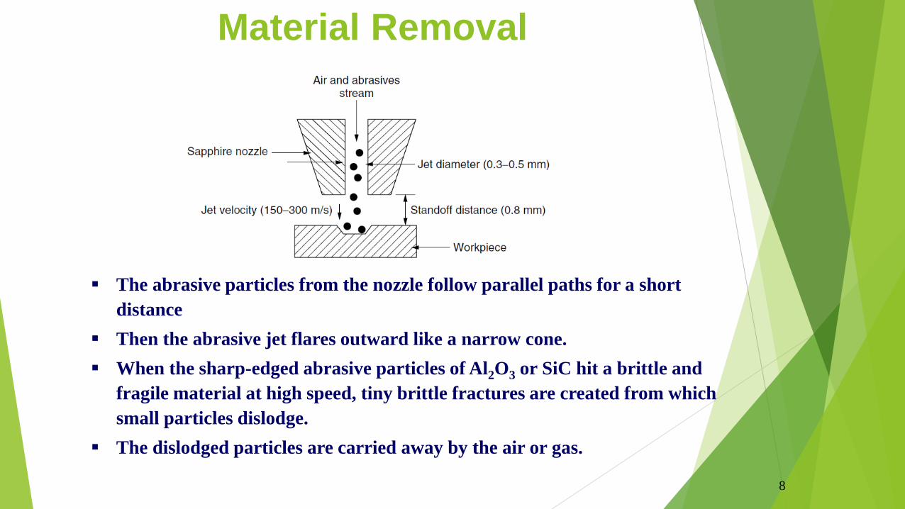
Material Removal
The abrasive particles from the nozzle follow parallel paths for a short
distance
Then the abrasive jet flares outward like a narrow cone.
When the sharp-edged abrasive particles of Al2O3 or SiC hit a brittle and
fragile material at high speed, tiny brittle fractures are created from which
small particles dislodge.
The dislodged particles are carried away by the air or gas.
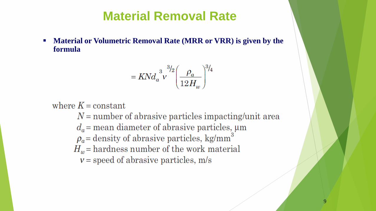
9
Material or Volumetric Removal Rate (MRR or VRR) is given by the formula
Material Removal Rate
10
MRR, machining accuracy, surface roughness and nozzle wear are influenced by
Size and distance of the nozzle.
Composition, strength, size, and shape of abrasives
Flow rate
Composition, pressure, and velocity of the carrier gas.
MRR is mainly dependent on the flow rate and size of abrasives.
Larger grain sizes produce greater removal rates.
At a particular pressure, the VRR increases with the abrasive flow rate up to an optimum value and then decreases with any further increase in flow rate. (Why?)
The mass flow rate of the gas decreases with an increase in the abrasive flow rate
Hence the mixing ratio increases and causes a decrease in the removal rate because of the decreasing energy available for material removal.
Process Parameters
11
Typical MRR is 16.4 mm3/min when cutting glass.
Cutting rates for metals vary from 1.6 to 4.1 mm3/min.
For harder ceramics, cutting rates are about 50 percent higher than those for glass – 24.6 mm3/min.
The minimum width of cut can be 0.13 mm.
Tolerances are typically within 0.05 mm by using good fixation and motion control.
Finished surface has a random or matte texture.
Attainable surface roughness - 0.2 to 1.5 µm using 10 and 50 µm particles, respectively.
Taper is present in deep cuts.
High nozzle pressures result in a greater removal rate, but the nozzle life is decreased.
Process Parameters – Contd.

12
Process Characteristics
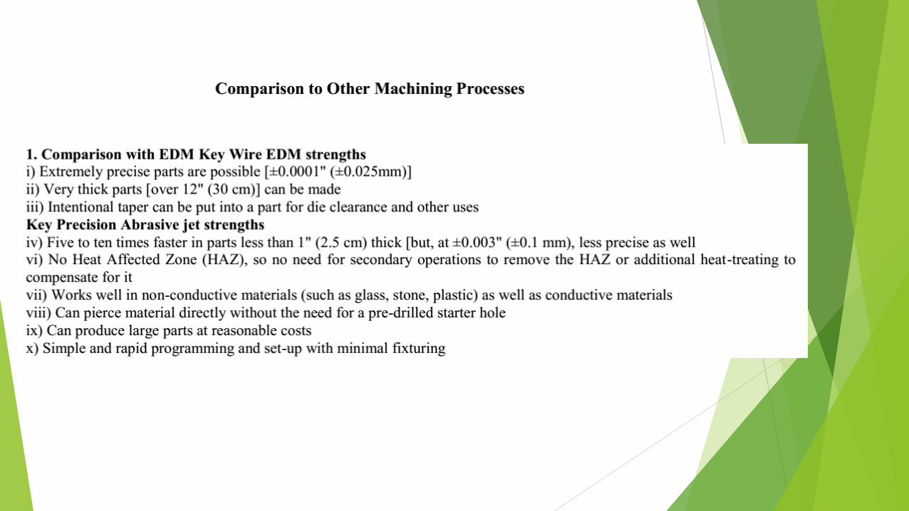
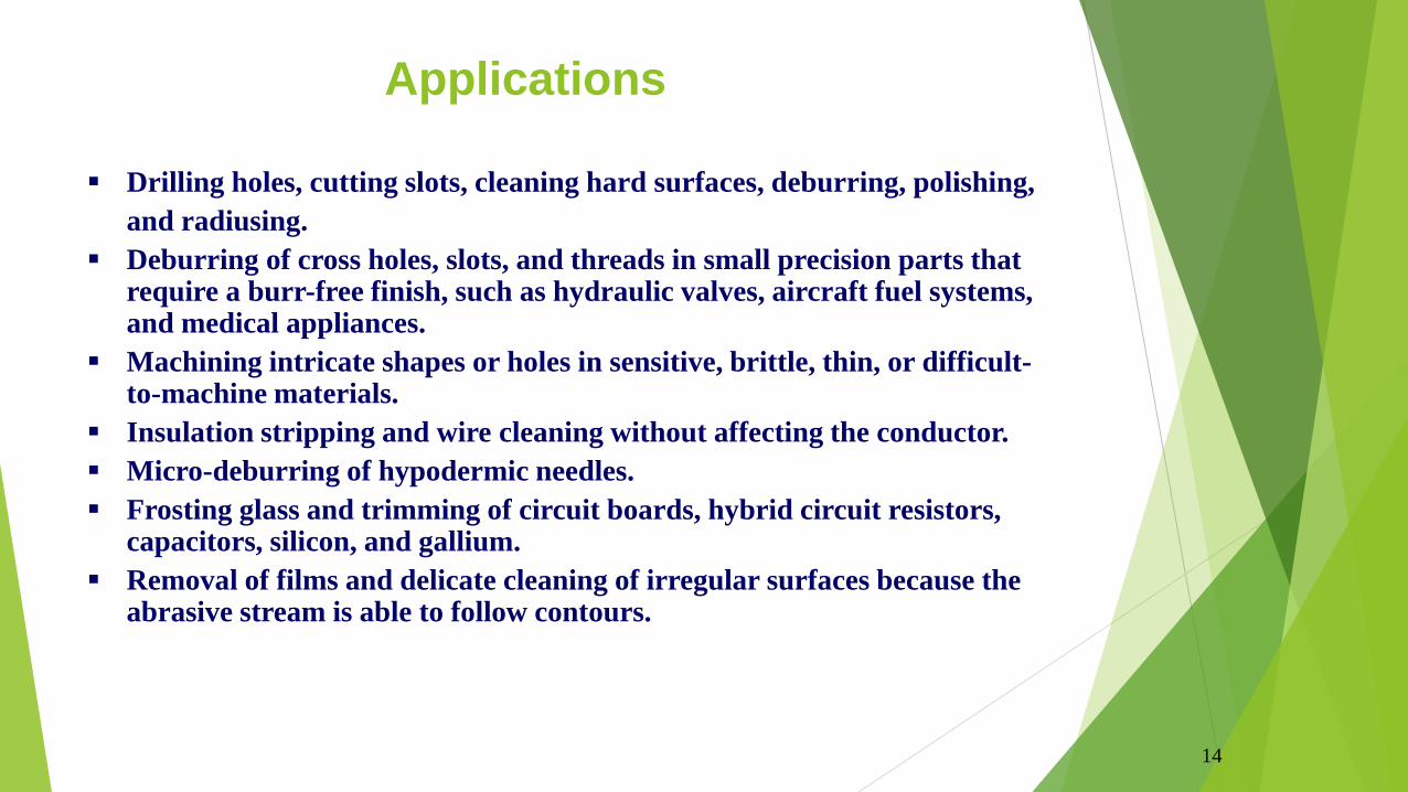
14
Drilling holes, cutting slots, cleaning hard surfaces, deburring, polishing,
and radiusing.
Deburring of cross holes, slots, and threads in small precision parts that require a burr-free finish, such as hydraulic valves, aircraft fuel systems, and medical appliances.
Machining intricate shapes or holes in sensitive, brittle, thin, or difficult-to-machine materials.
Insulation stripping and wire cleaning without affecting the conductor.
Micro-deburring of hypodermic needles.
Frosting glass and trimming of circuit boards, hybrid circuit resistors, capacitors, silicon, and gallium.
Removal of films and delicate cleaning of irregular surfaces because the abrasive stream is able to follow contours.
Applications
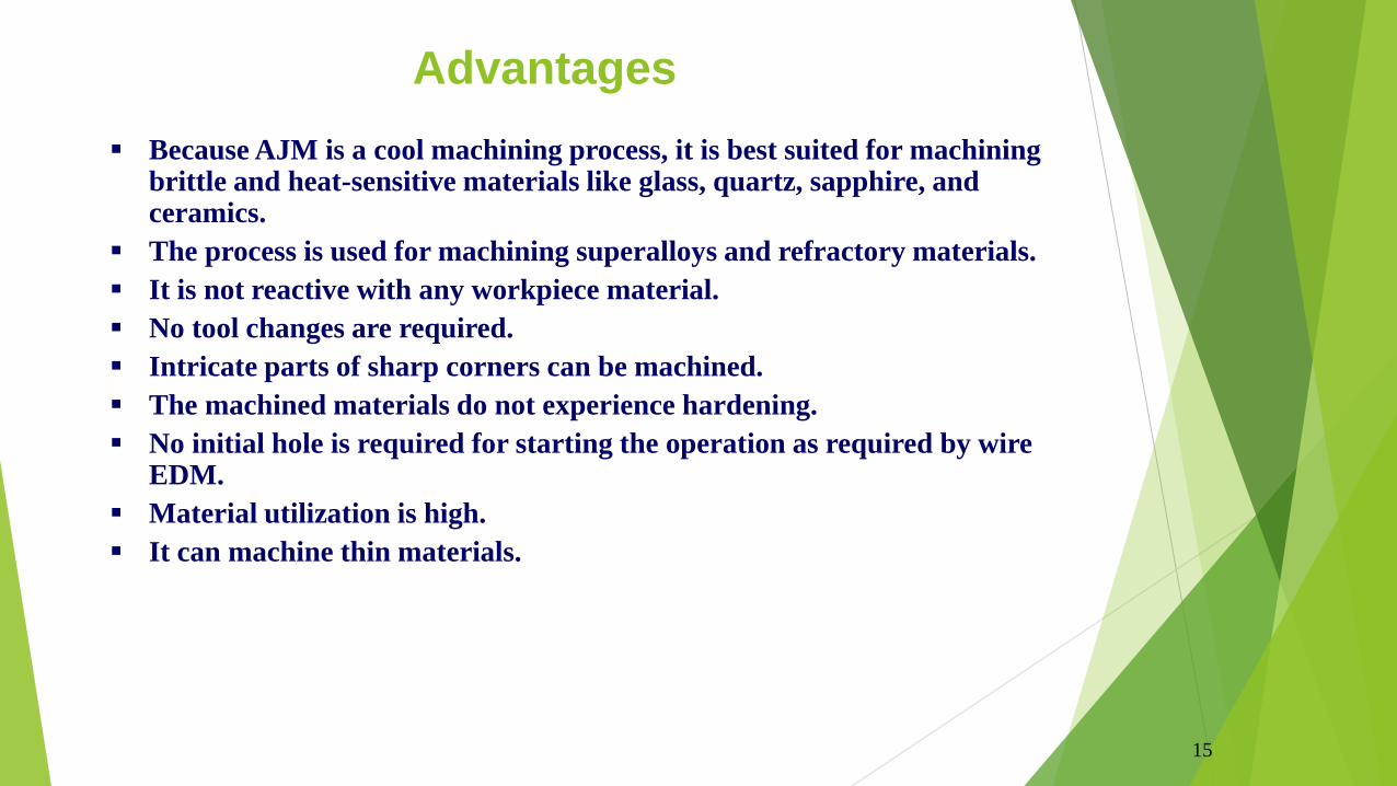
15
Because AJM is a cool machining process, it is best suited for machining brittle and heat-sensitive materials like glass, quartz, sapphire, and ceramics.
The process is used for machining superalloys and refractory materials.
It is not reactive with any workpiece material.
No tool changes are required.
Intricate parts of sharp corners can be machined.
The machined materials do not experience hardening.
No initial hole is required for starting the operation as required by wire EDM.
Material utilization is high.
It can machine thin materials.
Advantages
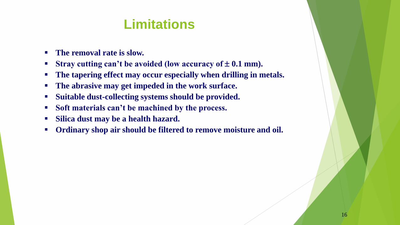
16
The removal rate is slow.
Stray cutting can’t be avoided (low accuracy of 0.1 mm).
The tapering effect may occur especially when drilling in metals.
The abrasive may get impeded in the work surface.
Suitable dust-collecting systems should be provided.
Soft materials can’t be machined by the process.
Silica dust may be a health hazard.
Ordinary shop air should be filtered to remove moisture and oil.
Limitations

USMPRODUCTION TECHNOLOGY
PROF. KUNALSINH KATHIA
HJD INSTITUTE KERA
Prof. Kunalsinh Kathia (HJDITER)

INTRODUCTION
Prof. Kunalsinh Kathia (HJDITER)
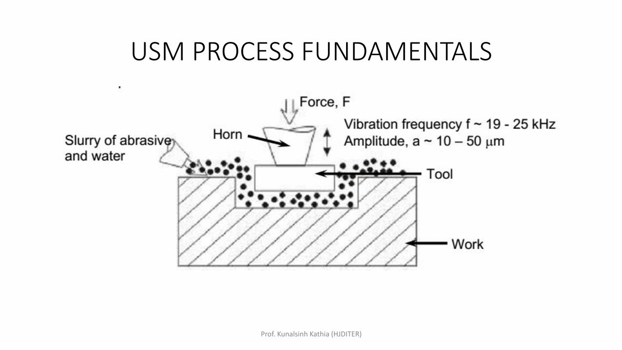
USM PROCESS FUNDAMENTALS
Prof. Kunalsinh Kathia (HJDITER)
MECHANISMS OF MATERIAL REMOVAL
Prof. Kunalsinh Kathia (HJDITER)
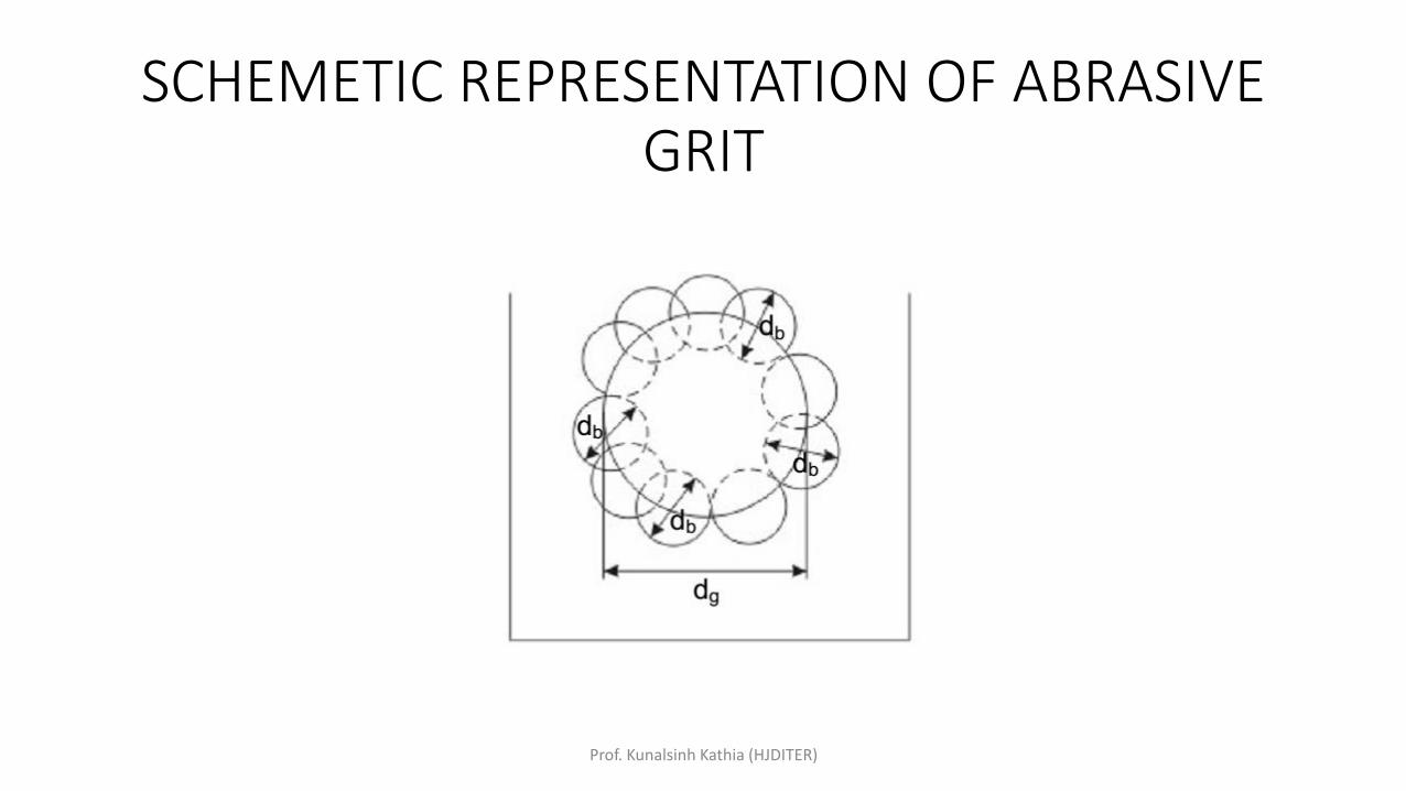
SCHEMETIC REPRESENTATION OF ABRASIVE GRIT
Prof. Kunalsinh Kathia (HJDITER)
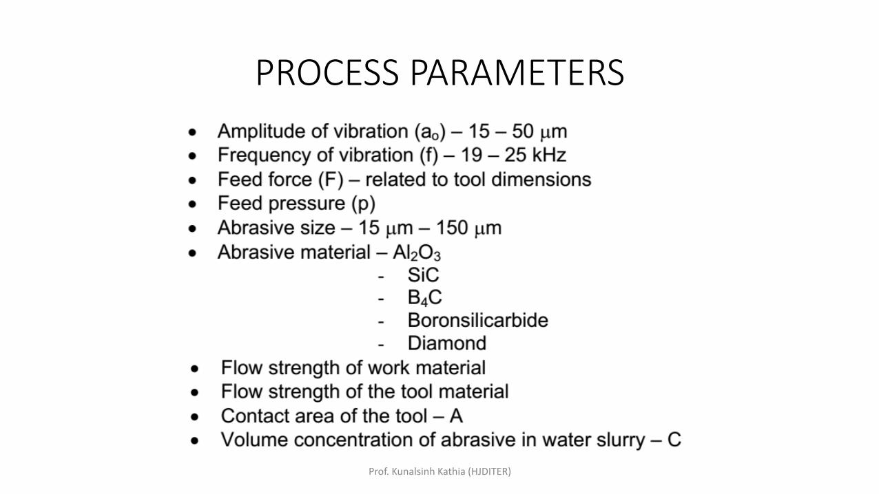
PROCESS PARAMETERS
Prof. Kunalsinh Kathia (HJDITER)
USM MACHINE
Prof. Kunalsinh Kathia (HJDITER)
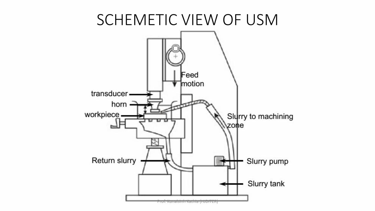
SCHEMETIC VIEW OF USM
Prof. Kunalsinh Kathia (HJDITER)
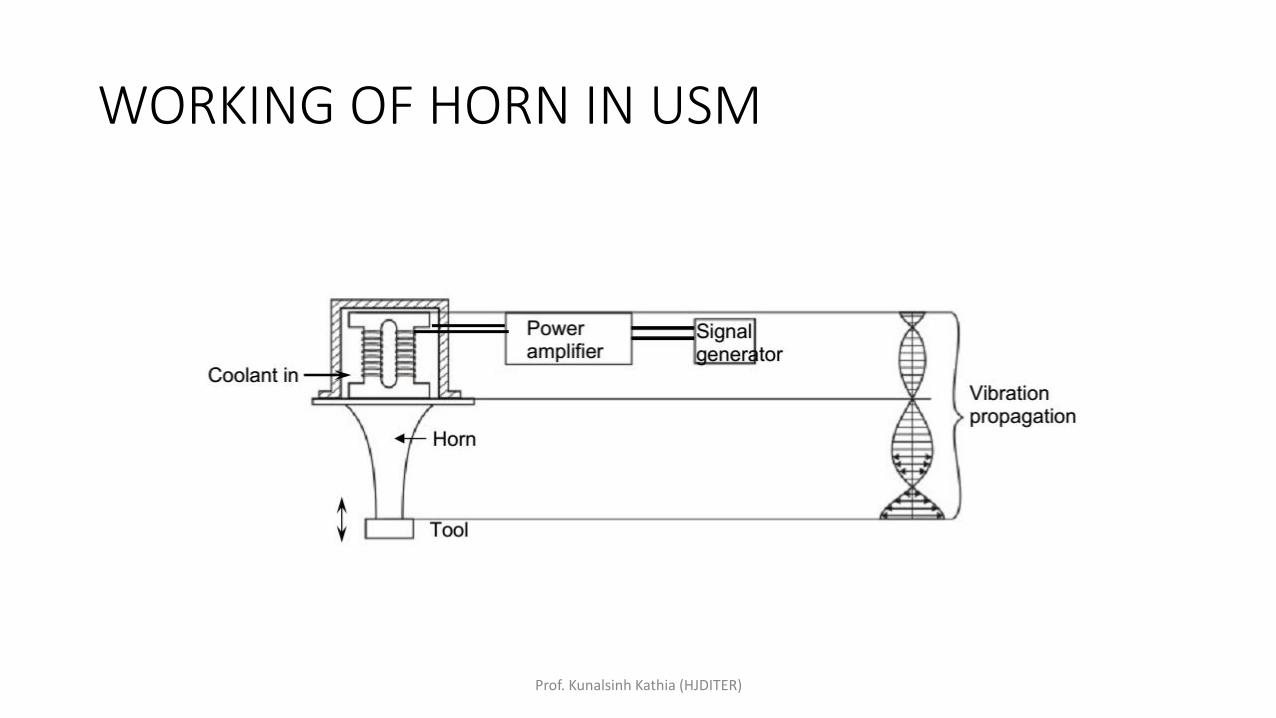
WORKING OF HORN IN USM
Prof. Kunalsinh Kathia (HJDITER)
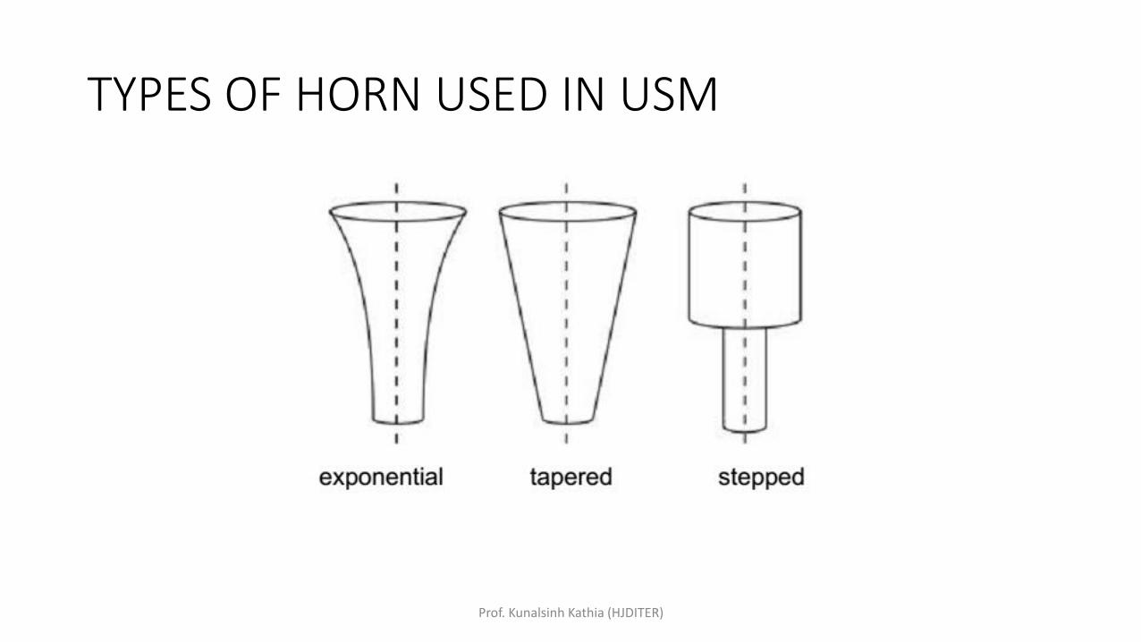
TYPES OF HORN USED IN USM
Prof. Kunalsinh Kathia (HJDITER)

APPLICATIONS
Prof. Kunalsinh Kathia (HJDITER)
ECMPRODUCTION TECHNOLOGY
MR.KUNALSINH R. KATHIA
MECHANICAL ENGINEERING DEPARTMENT
Prof. Kunalsinh Kathia (HJDITER)
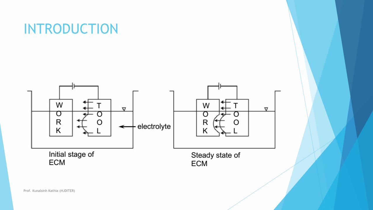
INTRODUCTION
Prof. Kunalsinh Kathia (HJDITER)
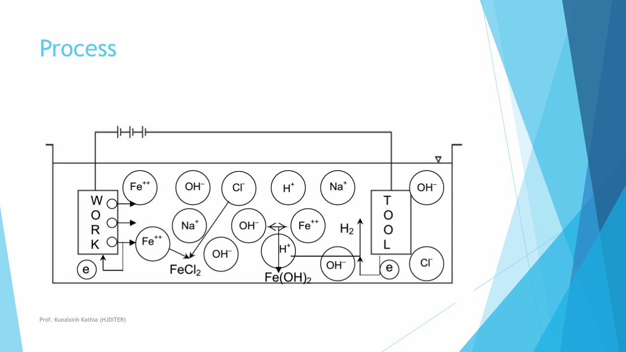
Process
Prof. Kunalsinh Kathia (HJDITER)
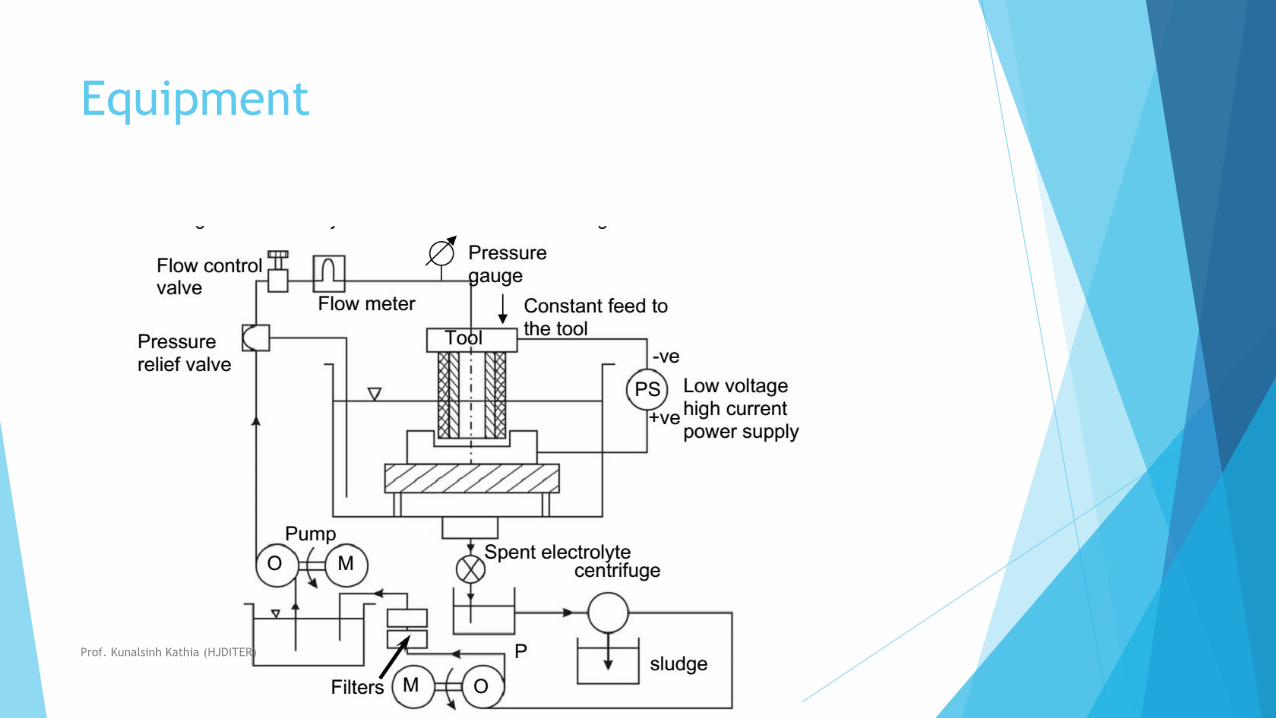
Equipment
Prof. Kunalsinh Kathia (HJDITER)
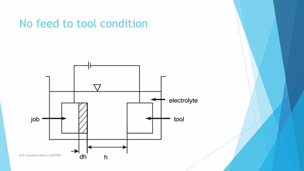
No feed to tool condition
Prof. Kunalsinh Kathia (HJDITER)
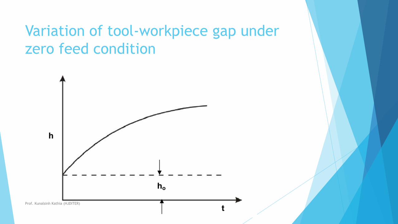
Variation of tool-workpiece gap under
zero feed condition
Prof. Kunalsinh Kathia (HJDITER)

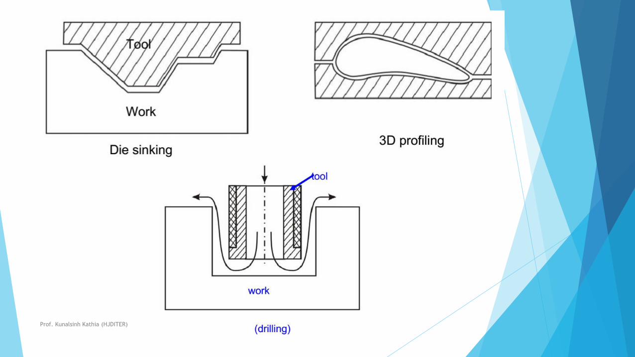
Applications
Prof. Kunalsinh Kathia (HJDITER)
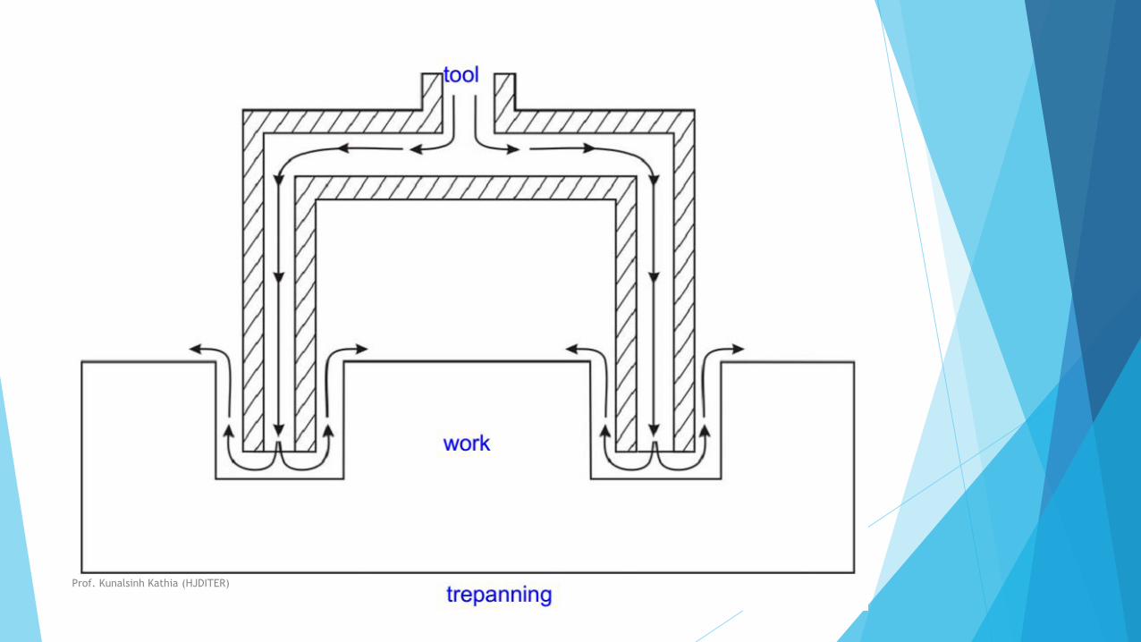
Ecm is used for
•Die sinking
• Profiling and contouring
•Trepanning
•Grinding
•Drilling
•Micro-machining
Prof. Kunalsinh Kathia (HJDITER)
Prof. Kunalsinh Kathia (HJDITER)
Prof. Kunalsinh Kathia (HJDITER)

Process Parameters
Prof. Kunalsinh Kathia (HJDITER)
EDMNON CONVENTIONAL MACHINING
PROF.KUNALSINH R. KATHIA
MECHANICAL ENGINEERING DEPARTMENT
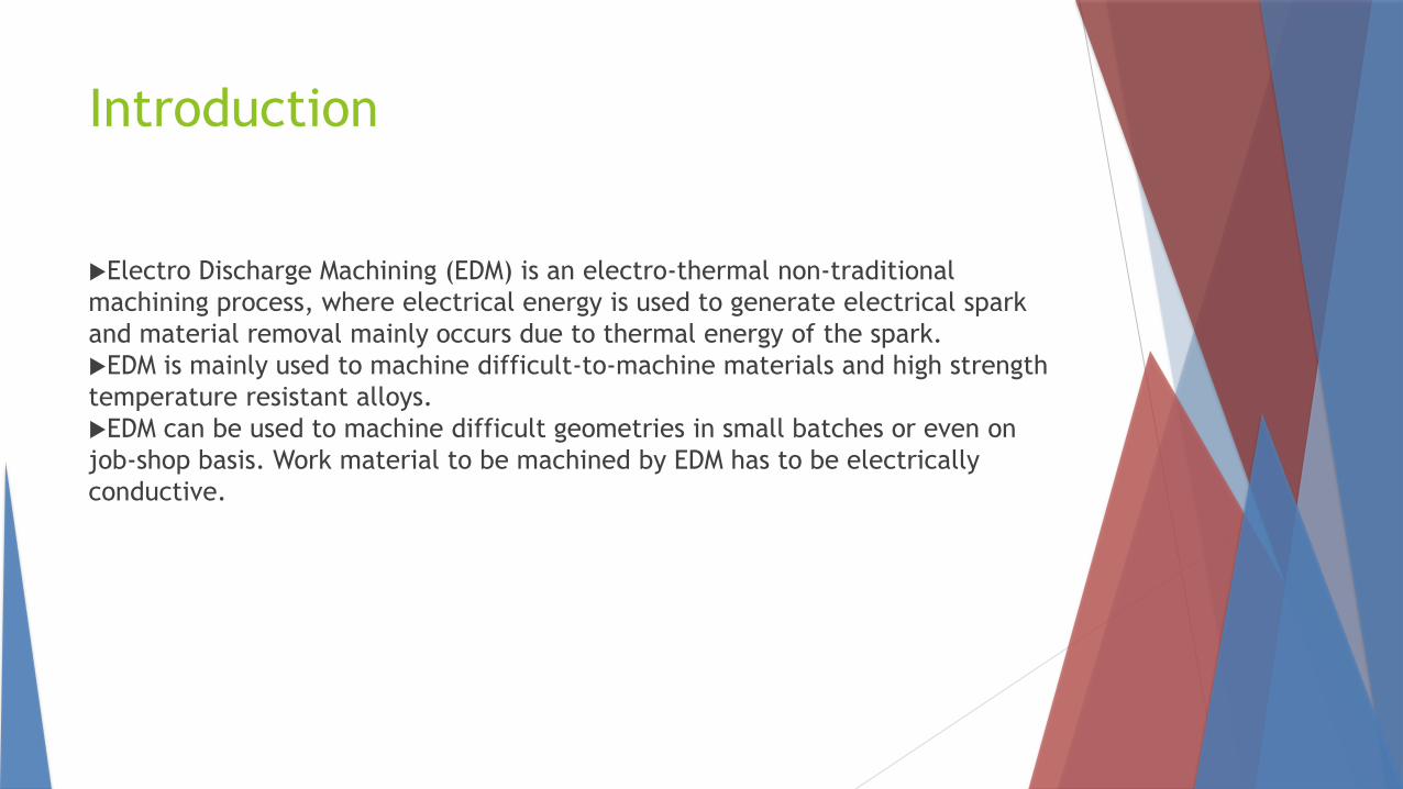
Introduction
Electro Discharge Machining (EDM) is an electro-thermal non-traditional
machining process, where electrical energy is used to generate electrical spark
and material removal mainly occurs due to thermal energy of the spark.
EDM is mainly used to machine difficult-to-machine materials and high strength
temperature resistant alloys.
EDM can be used to machine difficult geometries in small batches or even on
job-shop basis. Work material to be machined by EDM has to be electrically
conductive.
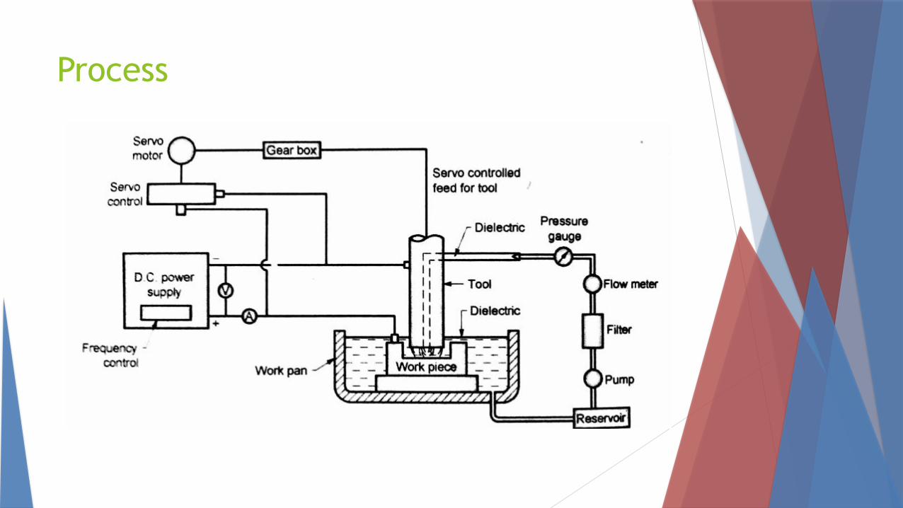
Process
Process
In EDM, a potential difference is applied between the tool and workpiece. Both
the tool and the work material are to be conductors of electricity.
The tool and the work material are immersed in a dielectric medium. Generally
kerosene or deionized water is used as the dielectric medium.
A gap is maintained between the tool and the workpiece.
Depending upon the applied potential difference and the gap between the tool
and workpiece, an electric field would be established.
Generally the tool is connected to the negative terminal of the generator and
the workpiece is connected to positive terminal.
As the electric field is established between the tool and the job, the free
electrons on the tool are subjected to electrostatic forces.
If the work function or the bonding energy of the electrons is less, electrons
would be emitted from the tool (assuming it to be connected to the negative
terminal). Such emission of electrons are called or termed as cold emission.
Process-2
The “cold emitted” electrons are then accelerated towards the job through the
dielectric medium.
As they gain velocity and energy, and start moving towards the job, there would
be collisions between the electrons and dielectric molecules.
Such collision may result in ionization of the dielectric molecule depending
upon the work function or ionization energy of the
dielectric molecule and the energy of the electron.
Thus, as the electrons get accelerated, more positive ions and electrons would
get generated due to collisions.
This cyclic process would increase the concentration of electrons and ions in
the dielectric medium between the tool and the job at the spark gap. The
concentration would be so high that the matter existing in that channel could be
characterized as “plasma”.
The electrical resistance of such plasma channel would be very less. Thus all of
a sudden, a large number of electrons will flow from the tool to the job and ions
from the job to the tool.
This is called avalanche motion of electrons.
Such movement of electrons and ions can be visually seen as a spark.
Process-2
The high speed electrons then impinge on the job and ions on the tool.
The kinetic energy of the electrons and ions on impact with the surface of the
job and tool respectively would be converted into thermal energy or heat flux.
Such intense localized heat flux leads to extreme instantaneous confined rise in
temperature which would be in excess of 10,000oC.
Process-2
Such localized extreme rise in temperature leads to material removal. Material
removal occurs due to instant vaporization of the material as well as due to
melting.
The molten metal is not removed completely but only partially. As the potential
difference is withdrawn as shown in Fig. 1, the plasma channel is no longer
sustained. As the plasma channel collapse, it generates pressure or shock waves,
which evacuates the molten material forming a crater of removed material
around the site of the spark.
Thus to summarise, the material removal in EDM mainly occurs due to
formation of shock waves as the plasma channel collapse owing to
discontinuation of applied potential difference.
Generally the work piece is made positive and the tool negative. Hence, the
electrons strike the job leading to crater formation due to high temperature and
melting and material removal.
Similarly, the positive ions impinge on the tool leading to tool wear. In EDM, the
generator is used to apply voltage pulses between the tool and the job.
A constant voltage is not applied. Only sparking is desired in EDM rather than
arcing. Arcing leads to localized material removal at a particular point whereas
Characteristics of EDM
(a) The process can be used to machine any work material if it is electrically
conductive
(b) Material removal depends on mainly thermal properties of the work
material rather than its strength, hardness etc. .
(c) In EDM there is a physical tool and geometry of the tool is the positive
impression of the hole or geometric feature machined
(d) The tool has to be electrically conductive as well. The tool wear once again
depends on the thermal properties of the tool material
(e) Though the local temperature rise is rather high, still due to very small
pulse on time, there is not enough time for the heat to diffuse and thus almost
no increase in bulk temperature takes place. Thus the heat affected zone is
limited to 2 – 4 μm of the spark crater.
(f) However rapid heating and cooling and local high temperature leads to
surface hardening which may be desirable in some applications
(g) Though there is a possibility of taper cut and overcut in EDM, they can be
controlled and compensated.
Dielectric
In EDM, as has been discussed earlier, material removal mainly occurs due to
thermal evaporation and melting. As thermal processing is required to be carried
out in absence of oxygen so that the process can be controlled and oxidation
avoided.
Oxidation often leads to poor surface conductivity (electrical) of the work piece
hindering further machining.
Hence, dielectric fluid should provide an oxygen free machining environment.
Further it should have enough strong dielectric resistance so that it does not
breakdown electrically too easily but at the same time ionize when electrons
collide with its molecule. Moreover, during sparking it should be thermally
resistant as well.
Dielectric
Generally kerosene and deionized water is used as dielectric fluid in EDM.
Tap water cannot be used as it ionizes too early and thus breakdown due to
presence of salts
as impurities occur. Dielectric medium is generally flushed around the spark
zone.
It is also applied through the tool to achieve efficient removal of molten
material.


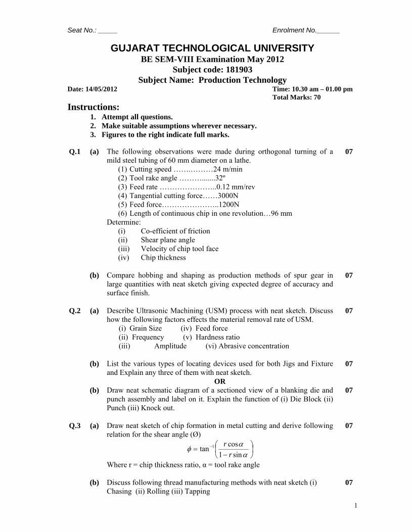
1
Seat No.: _____ Enrolment No.______
GUJARAT TECHNOLOGICAL UNIVERSITY BE SEM-VIII Examination May 2012
Subject code: 181903 Subject Name: Production Technology
Date: 14/05/2012 Time: 10.30 am – 01.00 pm Total Marks: 70 Instructions:
1. Attempt all questions. 2. Make suitable assumptions wherever necessary. 3. Figures to the right indicate full marks.
Q.1 (a) The following observations were made during orthogonal turning of a
mild steel tubing of 60 mm diameter on a lathe. (1) Cutting speed …….………24 m/min (2) Tool rake angle ……….......32º (3) Feed rate …………………..0.12 mm/rev (4) Tangential cutting force……3000N (5) Feed force…………………..1200N (6) Length of continuous chip in one revolution…96 mm
Determine: (i) Co-efficient of friction (ii) Shear plane angle (iii) Velocity of chip tool face (iv) Chip thickness
07
(b) Compare hobbing and shaping as production methods of spur gear in large quantities with neat sketch giving expected degree of accuracy and surface finish.
07
Q.2 (a) Describe Ultrasonic Machining (USM) process with neat sketch. Discuss
how the following factors effects the material removal rate of USM. (i) Grain Size (iv) Feed force (ii) Frequency (v) Hardness ratio (iii) Amplitude (vi) Abrasive concentration
07
(b) List the various types of locating devices used for both Jigs and Fixture and Explain any three of them with neat sketch.
07
OR (b) Draw neat schematic diagram of a sectioned view of a blanking die and
punch assembly and label on it. Explain the function of (i) Die Block (ii) Punch (iii) Knock out.
07
Q.3 (a) Draw neat sketch of chip formation in metal cutting and derive following
relation for the shear angle (Ø)
⎟⎠⎞
⎜⎝⎛−
= −
ααφ
sin1costan 1
rr
Where r = chip thickness ratio, α = tool rake angle
07
(b) Discuss following thread manufacturing methods with neat sketch (i) Chasing (ii) Rolling (iii) Tapping
07
2
OR Q.3 (a) Draw neat sketch of single point cutting tool with label of six major
angles and other terminology of it. Discuss essential characteristic and function of cutting fluids.
07
(b) Enlist different types of gears and draw gear tooth terminology. With appropriate example discuss plain indexing and compound indexing methods of manufacturing a gear on milling machine.
07
Q.4 (a) Calculate the different seeds available on spindle of a lathe and show
them on 1 x 2 x 3 (cross) and 1 x 2 x 3 (open) ray diagram using following data:
(1) Max spindle speed RPM = 166 (2) Min spindle speed RPM = 30 (3) No of spindle speed = 6
07
(b) Describe principle of Electrical Discharge Machining (EDM) with figure and state its advantages, limitation and application.
07
OR Q.4 (a) Explain single spindle automates and transfer machines with suitable
example. 07
(b) How are unconventional machining methods classified? Compare LBM and EBM process with different factors which consider for classification of unconventional machining.
07
Q.5 (a) Distinguish between a Jig and Fixture. Sketch different drill bushes useful
in drill jigs. 07
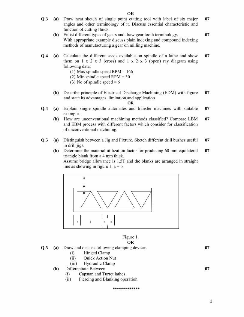
(b) Determine the material utilization factor for producing 60 mm equilateral triangle blank from a 4 mm thick. Assume bridge allowance is 1.5T and the blanks are arranged in straight line as showing in figure 1. a = b
Figure 1.
07
OR Q.5 (a) Draw and discuss following clamping devices
(i) Hinged Clamp (ii) Quick Action Nut (iii) Hydraulic Clamp
07
(b) Differentiate Between (i) Capstan and Turret lathes (ii) Piercing and Blanking operation
07
*************
b l b b
a
1
Seat No.: ________ Enrolment No.___________
GUJARAT TECHNOLOGICAL UNIVERSITY BE - SEMESTER–VIII • EXAMINATION – SUMMER 2013
Subject Code: 181903 Date: 15/05/2013 Subject Name: Production Technology Time: 10:30 am TO 01:00 pm Total Marks: 70 Instructions:
1. Attempt all questions. 2. Make suitable assumptions wherever necessary. 3. Figures to the right indicate full marks.
Q.1 (a) Define Non-conventional machining? Why do we need these processes?
Give classification of the Non conventional processes? 07
(b) Distinguish between jig and fixture. State advantages of jigs and fixtures. 07
Q.2 (a) Write in detail the methods of reducing the cutting forces in press working.
07
(b) Discuss the various types of pilots used in progressive die. 07 OR (b) Sketch and design a progressive die to make a steel washer 30 mm outside
diameter with 15 mm hole. From 1.6 mm thick steel sheet. The ultimate shear strength of the material is 320 N/mm2. Calculate,
a. Maximum punch force necessary to blank and punch the washer if both punches operate at the same time.
b. Punch and die size for piercing and blanking operation
07
Q.3 (a) Write short note on – “Lathe tool Dynamometer”. 07
(b) In orthogonal cutting, if the feed is 1.25 mm/rev and chip thickness after cutting is 2mm, determine the following.
1. Chip thickness ratio 2. Shear angle
The tool bit has a rake angle of 10º. If shear strength = 600 N/mm2 Width of cut = 10 mm Cutting speed = 30 m/min Co-efficient of friction = 0.9 Determine,
a. Shear force b. Friction angle c. Cutting force d. Horse power at the cutting tool
07
OR Q.3 (a) Draw Merchant’s force diagram. Derive the equations for frictional force,
normal reaction, shear force and normal force. 07
(b) The following equation for tool life has been obtained for H. S. S. tool. CdfVT =3.06.013.0 A 60 minute tool life was obtained while cutting at V = 40 m/min, f = 0.25 mm/rev and d= 2 mm. Calculate the effect on tool life if speed, feed and depth of cut are together increased by 25% and also if they are increased individually by 25%. Also give your comments.
07
2
Q.4 (a) What is LASER? Explain LBM. 07
(b) Describe the degrees of freedom for workpiece located in space. Draw a simple sketch to show the 3-2-1 locating principle and explain.
07
OR Q.4 (a) List various clamping devices used in jigs and fixtures. Sketch any two
clamping devices and explain its working. 07
(b) Write important functions of dielectric fluid and electrolyte. Also write various types of commonly used dielectric fluid and electrolyte.
07
Q.5 (a) Explain with the help of sketch, principle, types, and applications of gear
hobbing. 07
(b) Describe the essential parts of turret lathe. What is the field of application of turret lathe?
07
OR Q.5 (a) Write short note on Gear finishing process. 07
(b) Discuss the various types of multi spindle automats. 07
*************
1
Seat No.: ________ Enrolment No.___________
GUJARAT TECHNOLOGICAL UNIVERSITY BE – SEMESTER–VIII • Remedial EXAMINATION – WINTER 2013
Subject Code: 181903 Date: 17/09/2013 Subject Name: Production Technology Time: 03:00 pm – 05:30 pm Total Marks: 70 Instructions:
1. Attempt all questions. 2. Make suitable assumptions wherever necessary. 3. Figures to the right indicate full marks.
Q.1 (a) Draw a neat sketch of a single point cutting tool indicating its complete geometry on it.
07
(b) Draw a merchant circle diagram and derive expressions to show relationship among the different forces acting on the cutting tool and different parameter involved in metal cutting.
07
Q.2 (a) Classify the generating process for gear cutting ? Explain “Gear Hobbing” in detail.
07
(b) Describe each type of chip with the help of suitable sketch. 07 OR (b) What is tool life? State factors influencing on it in detail. 07
Q.3 (a) Explain with suitable diagram working of electro discharge machine. State its advantage, disadvantage and application.
07
(b) Explain Abrasive Jet machining with schematic diagram stating its advantages and limitation.
07
OR Q.3 (a) Explain principle of Ultrasonic machining with the help of neat diagram. State
its advantages and application. 07
(b) With neat sketch, explain the process of Electro –chemical grinding. State its limitation.
07
Q.4 (a) How the Presses are classified? Sketch and describe any one of it. 07 (b) What are automatic transfer machines? Write principle, advantages and
disadvantages of it. 07
OR Q.4 (a) What is difference between a capstan and turret lathe? Describe in brief with
the help of suitable sketch. 07
(b) Make a neat sketch of a die- set and describe its various details and accessories 07
Q.5 (a) Enlist types of Jig. Explain construction and working of template jig. 07 (b) Explain “Principle of location” in detail. 07 OR
Q.5 (a) Enlist types of Fixtures. Explain any two with sketch. 07 (b) Describe with neat sketch any three types of clamping device with their features
and application. 07
*************
1
Seat No.: ________ Enrolment No.___________
GUJARAT TECHNOLOGICAL UNIVERSITY BE - SEMESTER–VIII • EXAMINATION – SUMMER 2014
Subject Code: 181903 Date: 03-06-2014
Subject Name: Production Technology
Time: 10:30 am TO 01:00 pm Total Marks: 70 Instructions:
1. Attempt all questions.
2. Make suitable assumptions wherever necessary.
3. Figures to the right indicate full marks.
Q.1 (a) What are the main characteristics of cutting tool materials 03
(b) Explain in brief Taylor’s relationship for cutting speed-tool life. 04
(c) During an orthogonal machining ( turning) operation of C-40 steel, the following data
were obtained.
(1) Chip thickness = 0.45mm
(2) Width of cut = 2.5mm
(3) Feed = 0.25mm/rev
(4) Tangential cut force = 1130N
(5) Feed thrust force = 295N
(6) Cutting speed = 2.5m/s
(7) Rake angle = 10o
Calculate (1) Force of shear at shear plane
(2) Kinetic co-efficient of friction.
07
Q.2 (a) Discuss various types of tool wears and their causes. 07
(b) A 300mm dia. bar is turned at 45rev/min with depth of cut of 2mm and feed of
0.3mm/rev. The forces measured at the cutting tool point are
Cutting force = 1850N
Feed force = 450N
Calculate (1) power consumption
(2) specific cutting energy
07
OR
(b) The following equation for tool life is given for a turning operation
V T0.13
f0.77
d0.37
= C
A 60 min tool life was obtained while cutting at V = 30m/min, f = 0.3mm/rev and d =
2.5mm
Determine the changes in tool-life if the cutting speed, feed and depth of cut are
increased by 20% individually and also taken together.
07
Q.3 (a) Classify various non-conventional machining processes. 07
(b) Explain the working principle of EDM. What are the main process parameters . State
advantages of EDM.
07
OR
Q.3 (a) State various thread manufacturing methods. 03
(b) Differentiate between gear forming and gear generating methods. 04
(c) Explain gear finishing processes. 07
Q.4 (a) What are the advantages of using jigs and fixtures. 03
(b) Explain in brief Angle jig. 04
(c) Explain basic design steps for cam for single spindle automat. 07

2
OR
Q.4 (a) Explain in brief hydraulic clamp. 03
Q.4 (b) Explain in brief Indexing jig by taking suitable example. 04
(c) Differentiate between Capstan and turret lathe 07
Q.5 (a) How cutting force is calculated for press work. What are the various methods for
reducing force requirements.
07
(b) Explain in brief two pass layout in press work by taking suitable example. 07
OR
Q.5 (a) Explain various methods of mounting of punches. 07
(b) Explain various machine tool structures, based on rigidity. 07
*************
Recommended