Propulsion OverviewLaunch and Entry Vehicle Design
U N I V E R S I T Y O FMARYLAND
Propulsion Systems Design
• Rocket engine basics• Survey of the technologies• Propellant feed systems• Propulsion systems design
© 2008 David L. Akin - All rights reservedhttp://spacecraft.ssl.umd.edu1

Propulsion OverviewLaunch and Entry Vehicle Design
U N I V E R S I T Y O FMARYLAND
Propulsion TaxonomyMass Expulsion Non-Mass Expulsion
Non-ThermalThermal
Non-ChemicalChemical Solar Sail
Laser Sail
Microwave Sail
MagnetoPlasma
Monopropellants Bipropellants
LiquidsSolids Hybrids
Pressure-Fed Pump-Fed
Ion
MPDNuclear
Electrical
Solar
Air-Breathing ED Tether
Beamed
Cold Gas
2

Propulsion OverviewLaunch and Entry Vehicle Design
U N I V E R S I T Y O FMARYLAND
Propulsion TaxonomyMass Expulsion Non-Mass Expulsion
Non-ThermalThermal
Non-ChemicalChemical Solar Sail
Laser Sail
Microwave Sail
MagnetoPlasma
Monopropellants Bipropellants
LiquidsSolids Hybrids
Pressure-Fed Pump-Fed
Ion
MPDNuclear
Electrical
Solar
Air-Breathing ED Tether
Beamed
Cold Gas
3
Propulsion OverviewLaunch and Entry Vehicle Design
U N I V E R S I T Y O FMARYLAND
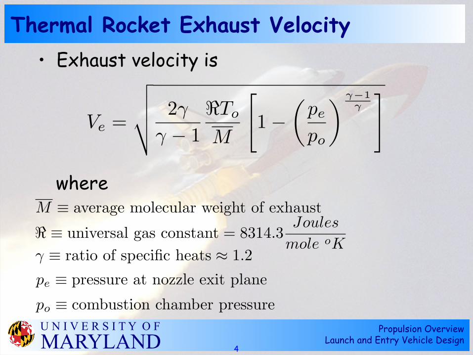
Thermal Rocket Exhaust Velocity• Exhaust velocity is
where
4
Ve =
!""# 2!
! ! 1"To
M
$1!
%pe
po
& !!1!
'
M ! average molecular weight of exhaust
! " universal gas constant = 8314.3Joules
mole oK! ! ratio of specific heats " 1.2pe ! pressure at nozzle exit planepo ! combustion chamber pressure

Propulsion OverviewLaunch and Entry Vehicle Design
U N I V E R S I T Y O FMARYLAND
Ideal Thermal Rocket Exhaust Velocity• Ideal exhaust velocity is
• This corresponds to an ideally expanded nozzle
• All thermal energy converted to kinetic energy of exhaust
• Only a function of temperature and molecular weight!
5
Ve =
!2!
! ! 1"To
M

Propulsion OverviewLaunch and Entry Vehicle Design
U N I V E R S I T Y O FMARYLAND
Thermal Rocket Performance• Thrust is
• Effective exhaust velocity
• Expansion ratio
€
T = ˙ m Ve + pe − pamb( )Ae
€
T = ˙ m c ⇒ c = Ve + pe − pamb( ) Ae
˙ m
€
AtAe
=γ +12
1γ −1 pe
p0
1γ γ +1
γ −11− pe
p0
γ −1γ
€
Isp =cg0
6

Propulsion OverviewLaunch and Entry Vehicle Design
U N I V E R S I T Y O FMARYLAND
A Word About Specific Impulse
• Defined as “thrust/propellant used”– English units: lbs thrust/(lbs prop/sec)=sec– Metric units: N thrust/(kg prop/sec)=m/sec
• Two ways to regard discrepancy -– “lbs” is not mass in English units - should be slugs– Isp = “thrust/weight flow rate of propellant”
• If the real intent of specific impulse is
Isp =T
mand T = mVe then Isp = Ve!!!
7

Propulsion OverviewLaunch and Entry Vehicle Design
U N I V E R S I T Y O FMARYLAND
Nozzle Design
• Pressure ratio p0/pe=100 (1470 psi-->14.7 psi)Ae/At=11.9
• Pressure ratio p0/pe=1000 (1470 psi-->1.47 psi)Ae/At=71.6
• Difference between sea level and ideal vacuum Ve
• Isp,vacuum=455 sec --> Isp,sl=333 sec
€
VeVe,ideal
= 1− pep0
γ −1γ
8

Propulsion OverviewLaunch and Entry Vehicle Design
U N I V E R S I T Y O FMARYLAND
Solid Rocket Motor
From G. P. Sutton, Rocket Propulsion Elements (5th ed.) John Wiley and Sons, 1986
9

Propulsion OverviewLaunch and Entry Vehicle Design
U N I V E R S I T Y O FMARYLAND
Solid Propellant Combusion
From G. P. Sutton, Rocket Propulsion Elements (5th ed.) John Wiley and Sons, 1986
10

Propulsion OverviewLaunch and Entry Vehicle Design
U N I V E R S I T Y O FMARYLAND
Solid Grain Configurations
From G. P. Sutton, Rocket Propulsion Elements (5th ed.) John Wiley and Sons, 1986
11

Propulsion OverviewLaunch and Entry Vehicle Design
U N I V E R S I T Y O FMARYLAND
Short-Grain Solid Configurations
From G. P. Sutton, Rocket Propulsion Elements (5th ed.) John Wiley and Sons, 1986
12

Propulsion OverviewLaunch and Entry Vehicle Design
U N I V E R S I T Y O FMARYLAND
Advanced Grain Configurations
From G. P. Sutton, Rocket Propulsion Elements (5th ed.) John Wiley and Sons, 1986
13
Propulsion OverviewLaunch and Entry Vehicle Design
U N I V E R S I T Y O FMARYLAND
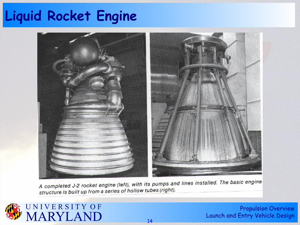
Liquid Rocket Engine
14

Propulsion OverviewLaunch and Entry Vehicle Design
U N I V E R S I T Y O FMARYLAND
Liquid Propellant Feed Systems
15

Propulsion OverviewLaunch and Entry Vehicle Design
U N I V E R S I T Y O FMARYLAND
Space Shuttle OMS Engine
From G. P. Sutton, Rocket Propulsion Elements (5th ed.) John Wiley and Sons, 1986
16

Propulsion OverviewLaunch and Entry Vehicle Design
U N I V E R S I T Y O FMARYLAND
Turbopump Fed Liquid Rocket Engine
From G. P. Sutton, Rocket Propulsion Elements (5th ed.) John Wiley and Sons, 1986
17

Propulsion OverviewLaunch and Entry Vehicle Design
U N I V E R S I T Y O FMARYLAND
Sample Pump-fed Engine Cycles
From G. P. Sutton, Rocket Propulsion Elements (5th ed.) John Wiley and Sons, 1986
18

Propulsion OverviewLaunch and Entry Vehicle Design
U N I V E R S I T Y O FMARYLAND
Gas Generator Cycle Engine
From G. P. Sutton, Rocket Propulsion Elements (5th ed.) John Wiley and Sons, 1986
19

Propulsion OverviewLaunch and Entry Vehicle Design
U N I V E R S I T Y O FMARYLAND
SSME Engine Cycle
From G. P. Sutton, Rocket Propulsion Elements (5th ed.) John Wiley and Sons, 1986
20

Propulsion OverviewLaunch and Entry Vehicle Design
U N I V E R S I T Y O FMARYLAND
Liquid Rocket Engine Cutaway
From G. P. Sutton, Rocket Propulsion Elements (5th ed.) John Wiley and Sons, 1986
21

Propulsion OverviewLaunch and Entry Vehicle Design
U N I V E R S I T Y O FMARYLAND
H-1 Engine Injector Plate
22
Propulsion OverviewLaunch and Entry Vehicle Design
U N I V E R S I T Y O FMARYLAND
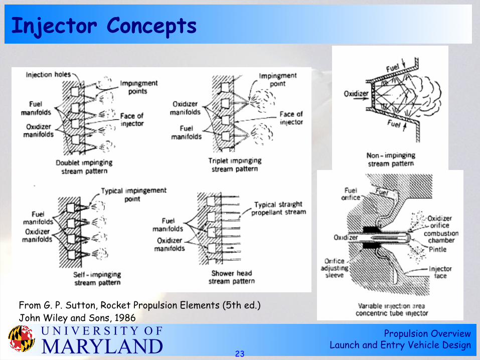
Injector Concepts
From G. P. Sutton, Rocket Propulsion Elements (5th ed.) John Wiley and Sons, 1986
23

Propulsion OverviewLaunch and Entry Vehicle Design
U N I V E R S I T Y O FMARYLAND
Solid Rocket Nozzle (Heat-Sink)
From G. P. Sutton, Rocket Propulsion Elements (5th ed.) John Wiley and Sons, 1986
24

Propulsion OverviewLaunch and Entry Vehicle Design
U N I V E R S I T Y O FMARYLAND
Ablative Nozzle Schematic
From G. P. Sutton, Rocket Propulsion Elements (5th ed.) John Wiley and Sons, 1986
25

Propulsion OverviewLaunch and Entry Vehicle Design
U N I V E R S I T Y O FMARYLAND
Active Chamber Cooling Schematic
From G. P. Sutton, Rocket Propulsion Elements (5th ed.) John Wiley and Sons, 1986
26

Propulsion OverviewLaunch and Entry Vehicle Design
U N I V E R S I T Y O FMARYLAND
Boundary Layer Cooling Approaches
From G. P. Sutton, Rocket Propulsion Elements (5th ed.) John Wiley and Sons, 1986
27

Propulsion OverviewLaunch and Entry Vehicle Design
U N I V E R S I T Y O FMARYLAND
Hybrid Rocket Schematic
From G. P. Sutton, Rocket Propulsion Elements (5th ed.) John Wiley and Sons, 1986
28

Propulsion OverviewLaunch and Entry Vehicle Design
U N I V E R S I T Y O FMARYLAND
Hybrid Rocket Combustion
From G. P. Sutton, Rocket Propulsion Elements (5th ed.) John Wiley and Sons, 1986
29

Propulsion OverviewLaunch and Entry Vehicle Design
U N I V E R S I T Y O FMARYLAND
Thrust Vector Control Approaches
From G. P. Sutton, Rocket Propulsion Elements (5th ed.) John Wiley and Sons, 1986
30

Propulsion OverviewLaunch and Entry Vehicle Design
U N I V E R S I T Y O FMARYLAND
Apollo Reaction Control System Thrusters
31

Propulsion OverviewLaunch and Entry Vehicle Design
U N I V E R S I T Y O FMARYLAND
Space Shuttle Primary RCS Engine
From G. P. Sutton, Rocket Propulsion Elements (5th ed.) John Wiley and Sons, 1986
32

Propulsion OverviewLaunch and Entry Vehicle Design
U N I V E R S I T Y O FMARYLAND
Monopropellant Engine Design
From G. P. Sutton, Rocket Propulsion Elements (5th ed.) John Wiley and Sons, 1986
33

Propulsion OverviewLaunch and Entry Vehicle Design
U N I V E R S I T Y O FMARYLAND
Cold-gas Propellant Performance
From G. P. Sutton, Rocket Propulsion Elements (5th ed.) John Wiley and Sons, 1986
34

Propulsion OverviewLaunch and Entry Vehicle Design
U N I V E R S I T Y O FMARYLAND
Pressurization System Analysis
Pg0, Vg
PL, VL
Pgf, Vg
PL, VL
Adiabatic Expansion of Pressurizing Gas
Initial Final
€
pg,0Vgγ = pg, fVg
γ + plVl
γ
Known quantities:
Pg,0=Initial gas pressure
Pg,f=Final gas pressure
PL=Operating pressure of propellant tank(s)
VL=Volume of propellant tank(s)
Solve for gas volume Vg
35

Space Systems Laboratory – University of Maryland
Low
-Cos
t Ret
urn
to th
e M
oon
Boost Module Propellant Tanks• Gross mass 23,000 kg
– Inert mass 2300 kg– Propellant mass 20,700 kg– Mixture ratio N2O4/A50 = 1.8 (by mass)
• N2O4 tank– Mass = 13,310 kg– Density = 1450 kg/m3
– Volume = 9.177 m3 --> rsphere=1.299 m
• Aerozine 50 tank– Mass = 7390 kg– Density = 900 kg/m3
– Volume = 8.214 m3 --> rsphere=1.252 m

Space Systems Laboratory – University of Maryland
Low
-Cos
t Ret
urn
to th
e M
oon
Boost Module Main Propulsion• Total propellant volume VL = 17.39 m3
• Assume engine pressure p0 = 250 psi• Tank pressure pL = 1.25*p0 = 312 psi• Final GHe pressure pg,f = 75 psi + pL = 388
psi• Initial GHe pressure pg,0 = 4500 psi • Conversion factor 1 psi = 6892 Pa• Ratio of specific heats for He = 1.67
• Vg = 3.713 m3 • Ideal gas: T=300°K --> ρ=49.7 kg/m3 (300 psi = 31.04 MPa) MHe=185.1 kg
€
4500 psi( )Vg1.67 = 388 psi( )Vg
1.67 + 312 psi( ) 17.39 m 3( )1.67
€
ρHe =pg,0M ℜT0
Propulsion OverviewLaunch and Entry Vehicle Design
U N I V E R S I T Y O FMARYLAND
Air-Breathing Propulsion
• Much of the total energy required is to accelerate propellants for the last phases of launch
• Typical (LOX/LH2) propellants are 86% oxygen by mass
• Logical conclusion: take in oxygen from ambient air during early portion of launch trajectory
38
(Isp = 450 sec! Isp,fuel = 3150 sec)

Propulsion OverviewLaunch and Entry Vehicle Design
U N I V E R S I T Y O FMARYLAND
Hypersonic Research Engine
39
http://www.onera.fr/conferences-en/ramjet-scramjet-pde/#scramjet

Propulsion OverviewLaunch and Entry Vehicle Design
U N I V E R S I T Y O FMARYLAND
X-43A Hypersonic Flight Test
40
http://hapb-www.larc.nasa.gov/Public/Projects/Hyperx.html

Propulsion OverviewLaunch and Entry Vehicle Design
U N I V E R S I T Y O FMARYLAND
Scramjet-Airframe Integration
41
“NASA Hyper-X Program Demonstrates Scramjet Technologies” NASA Facts FS-2004-10-98-LaRC

Propulsion OverviewLaunch and Entry Vehicle Design
U N I V E R S I T Y O FMARYLAND
X-43A Film Clip
42
Propulsion OverviewLaunch and Entry Vehicle Design
U N I V E R S I T Y O FMARYLAND
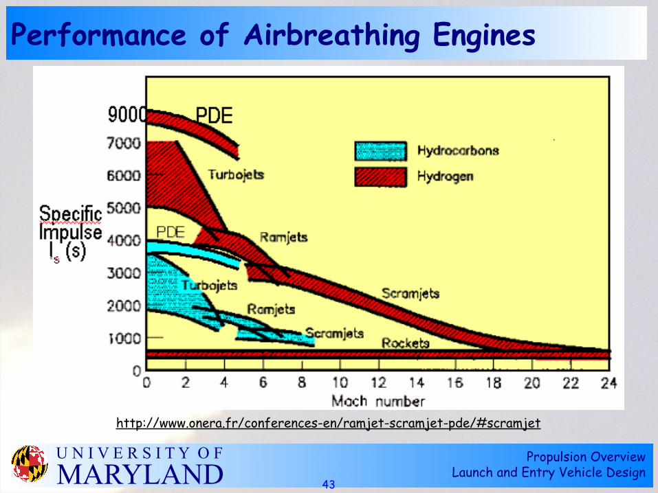
Performance of Airbreathing Engines
43
http://www.onera.fr/conferences-en/ramjet-scramjet-pde/#scramjet

Propulsion OverviewLaunch and Entry Vehicle Design
U N I V E R S I T Y O FMARYLAND
Constraints on Airbreathing Trajectories
44
http://www.onera.fr/conferences-en/ramjet-scramjet-pde/#scramjet

Propulsion OverviewLaunch and Entry Vehicle Design
U N I V E R S I T Y O FMARYLAND
Design Trends of Air-Breathing Propulsion
45
C. Trefny, “An Air-Breathing Launch Vehicle Concept for Single-Stage-to-Orbit” AIAA 99-2730

Propulsion OverviewLaunch and Entry Vehicle Design
U N I V E R S I T Y O FMARYLAND
Nuclear Thermal Rockets
• Heat propellants by passing through nuclear reactor
• Isp limited by temperature limits on reactor elements (~900 sec for H2 propellant)
• Mass impacts of reactor, shielding
• High thrust system
46

Propulsion OverviewLaunch and Entry Vehicle Design
U N I V E R S I T Y O FMARYLAND
Speculative Designs Including Nuclear
47
Aerojet General, “Payload, Cost, and Reliability Analysis of Saturn C-5 and Nova with NERVA or Chemical Third Stages” AGC-2279, June 1962
Recommended