www.regulus.eu
Energy-saving solutions
Protection and Control
of Solid Fuel Boilers
thermal relief valves & backup power supplies
load valves & load units
draft regulators

2 Protection and Control
Energy-saving solutions

1Protection and Control
Energy-saving solutions
CONTENTS
BOILER PROTECTION AGAINST OVERHEATING
Two-way Thermal Relief Valves:
3 Insulated DBV2
Thermal Safety Relief Valve
4 Insulated DBV1
Thermal Relief Valve
One-way Thermal Relief Valves:
5 JBV1
Thermal Relief Valve
6 BVTS
Thermal Safety Relief Valves with capillary
Backup Power Supplies:
8 PG 500 Compact
Backup Power Supplies for circulation pumps
9 PG 500
Backup Power Supplies for circulation pumps
10 PG 600 S
Backup Power Supplies for circulation pumps
PROTECTION AGAINST BOILER CORROSION AND FOULING
Loas Units:
12 RegulusBIO
Load Units for heating systems w. solid fuel boilers
16 RegulusRGMAT
Load Units with thermostatic mixing
25 ThermoMat
Load Units with thermostatic mixing and floating non-return valve
26 RegulusTOP
Load Units with electric actuated mixing
Load Valves:
30 TSVB
Valves for return temperature control, with automatic bypass balancing
30 TSV
Valves for return temperature control, with manual bypass balancing
Circulation pumps performance curves:
42 Grundfos
Circulation Pumps
43 Wilo
Circulation Pumps
BOILER OUTPUT CONTROL
46 RT4
Thermostatic Draft Regulators
48 RT3E
Thermostatic Draft Regulators, electric operated
2 Protection and Control
Energy-saving solutions
BOILER PROTECTION AGAINST OVERHEATING
BOILER PROTECTION AGAINST FOULING AND CORROSION
During burning steam is released from the fuel. If the boiler is hot enough, the steam leaves through the chimney together
with the flue gas. However, if the flue gas gets cooler on the boiler mantle, steam condensation occurs there. The condensate
may contain very aggressive combustion products that cause fast corrosion and deposit formation on heat transfer surfaces
(tarring).
By mixing cool return water from a heating system with hot water from the boiler flow the
boiler heat transfer surfaces are kept warmer and no condensation occurs. This makes their
service life significantly longer and the boiler efficiency higher.
Thermostatic draft regulators keep the outgoing temperature from a solid fuel boiler at the value selected by the regulator
knob. They control combustion air dampers via chains, controlling this way the boiler output. Their advantage is a robust,
mechanically sturdy and thermally resistant build. Their double scale enables horizontal as
well as vertical installation. They are fitted with high quality thermostatic elements made by
a French manufacturer that guarantee precise operation and a long service life.
Electric controlled regulators work in the same manner, moreover they can reduce outgoing
temperature from a boiler on electric signal. This way the boiler temperature and output can
be controlled by a room thermostat or another electronic controller.
BOILER OUTPUT CONTROL
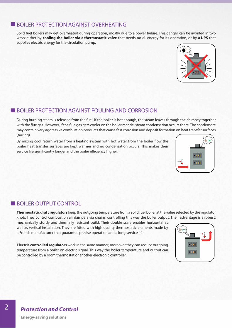
Solid fuel boilers may get overheated during operation, mostly due to a power failure. This danger can be avoided in two
ways: either by cooling the boiler via a thermostatic valve that needs no el. energy for its operation, or by a UPS that
supplies electric energy for the circulation pump.
3Protection and Control
Energy-saving solutions
159
G3/4"
56
227
85
131
65
OPENING TEMPERATURE 97 ± 2 °C
MAX. WORKING PRESSURE - HEATING WATER 4 bar
MAX. WORKING PRESSURE - COLD WATER 6 bar
PIPE CONNECTION G 3/4“ M
HEAT SOURCE CONNECTION R 3/4“ M tapered thread
WEIGHT 0.70 kg
Code
Insulated DBV2 16627
DBV2 in T-piece, 6/4” F, insulated 16863
Models
BOILER PROTECTION AGAINST OVERHEATING
Two-way Thermal Relief Valves
Connection in a systemDimensions
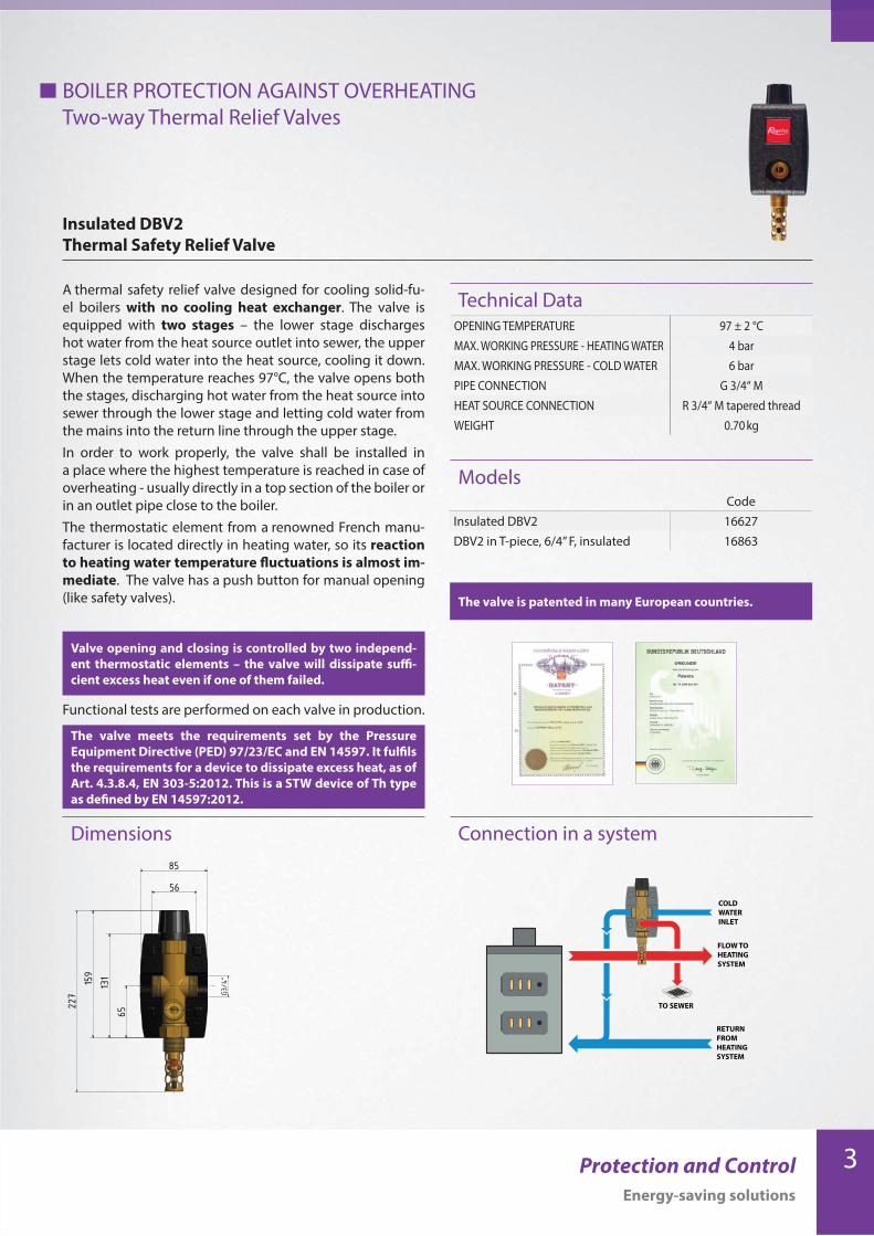
A thermal safety relief valve designed for cooling solid-fu-
el boilers with no cooling heat exchanger. The valve is
equipped with two stages – the lower stage discharges
hot water from the heat source outlet into sewer, the upper
stage lets cold water into the heat source, cooling it down.
When the temperature reaches 97°C, the valve opens both
the stages, discharging hot water from the heat source into
sewer through the lower stage and letting cold water from
the mains into the return line through the upper stage.
In order to work properly, the valve shall be installed in
a place where the highest temperature is reached in case of
overheating - usually directly in a top section of the boiler or
in an outlet pipe close to the boiler.
The thermostatic element from a renowned French manu-
facturer is located directly in heating water, so its reaction
to heating water temperature fluctuations is almost im-
mediate. The valve has a push button for manual opening
(like safety valves).
Functional tests are performed on each valve in production.
Insulated DBV2
Thermal Safety Relief Valve
Technical Data
Valve opening and closing is controlled by two independ-
ent thermostatic elements – the valve will dissipate suffi-
cient excess heat even if one of them failed.
The valve is patented in many European countries.
The valve meets the requirements set by the Pressure
Equipment Directive (PED) 97/23/EC and EN 14597. It fulfils
the requirements for a device to dissipate excess heat, as of
Art. 4.3.8.4, EN 303-5:2012. This is a STW device of Th type
as defined by EN 14597:2012.
COLD
WATER
INLET
FLOW TO
HEATING
SYSTEM
RETURN
FROM
HEATING
SYSTEM
TO SEWER

4 Protection and Control
Energy-saving solutions
Ventil je patentován v řadě evropských zemí.
OPENING TEMPERATURE 97 ± 2 °C
MAX. WORKING PRESSURE - HEATING WATER 4 bar
MAX. WORKING PRESSURE - COLD WATER 6 bar
PIPE CONNECTION G 3/4“ M
HEAT SOURCE CONNECTION R 3/4“ M tapered thread
WEIGHT 0.70 kg
ModelsCode
Insulated DBV1 16912
DBV1 in T-piece, 6/4” F, insulated 16913
147
199 11
8
5685
G3/4"
62
BOILER PROTECTION AGAINST OVERHEATING
Two-way Thermal Relief Valves
Insulated DBV1
Thermal Relief Valve
Connection in a systemDimensions
A thermal relief valve designed for cooling solid-fuel boilers
with no cooling heat exchanger. When the temperature
reaches 97°C, the valve opens and lets cold water in from
the mains. It cools the boiler down, preventing its overheat-
ing. Hot water is discharged into a sewer.
In order to work properly, the valve shall be installed in
a place where the highest temperature is reached in case of
overheating - usually directly in a top section of the boiler or
in an outlet pipe close to the boiler.
The thermostatic element from a renowned French manu-
facturer is located directly in heating water, so its reaction
to heating water temperature fluctuations is almost im-
mediate. The valve has a push button for manual opening
(like safety valves).
Functional tests are performed on each valve in production.
Technical Data
The valve is patented in many European countries.
COLD
WATER
INLET
FLOW TO
HEATING
SYSTEM
RETURN
FROM
HEATING
SYSTEM
TO SEWER
5Protection and Control
Energy-saving solutions
BOILER PROTECTION AGAINST OVERHEATING
Two-way Thermal Relief Valves
DBV1
Thermal Relief Valve
Connection in a systemDimensions
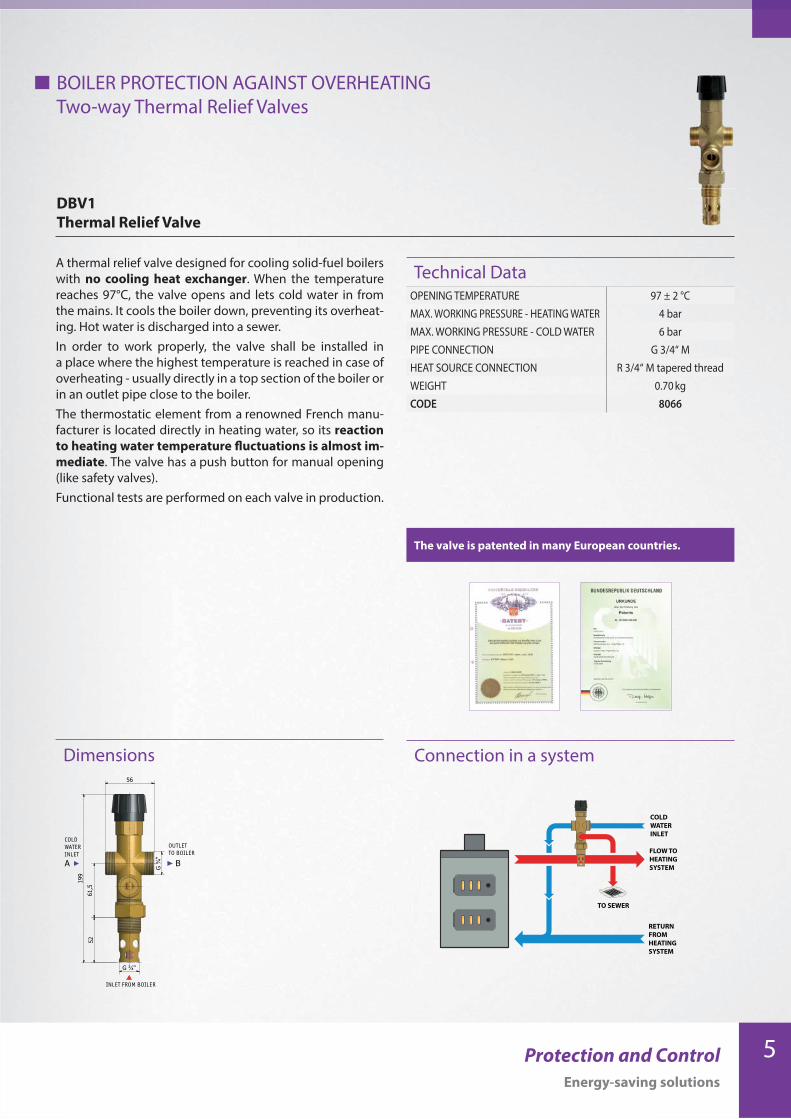
A thermal relief valve designed for cooling solid-fuel boilers
with no cooling heat exchanger. When the temperature
reaches 97°C, the valve opens and lets cold water in from
the mains. It cools the boiler down, preventing its overheat-
ing. Hot water is discharged into a sewer.
In order to work properly, the valve shall be installed in
a place where the highest temperature is reached in case of
overheating - usually directly in a top section of the boiler or
in an outlet pipe close to the boiler.
The thermostatic element from a renowned French manu-
facturer is located directly in heating water, so its reaction
to heating water temperature fluctuations is almost im-
mediate. The valve has a push button for manual opening
(like safety valves).
Functional tests are performed on each valve in production.
Technical Data
The valve is patented in many European countries.
OPENING TEMPERATURE 97 ± 2 °C
MAX. WORKING PRESSURE - HEATING WATER 4 bar
MAX. WORKING PRESSURE - COLD WATER 6 bar
PIPE CONNECTION G 3/4“ M
HEAT SOURCE CONNECTION R 3/4“ M tapered thread
WEIGHT 0.70 kg
CODE 8066
COLD
WATER
INLET
OUTLET
TO BOILER
INLET FROM BOILER
A B
199
61,5
G ¾"
G ¾
"
56
52
COLD
WATER
INLET
FLOW TO
HEATING
SYSTEM
RETURN
FROM
HEATING
SYSTEM
TO SEWER
6 Protection and Control
Energy-saving solutions
Connection in a system
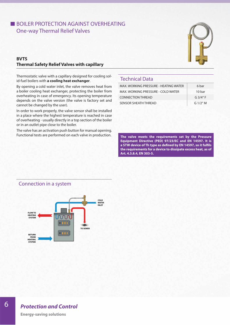
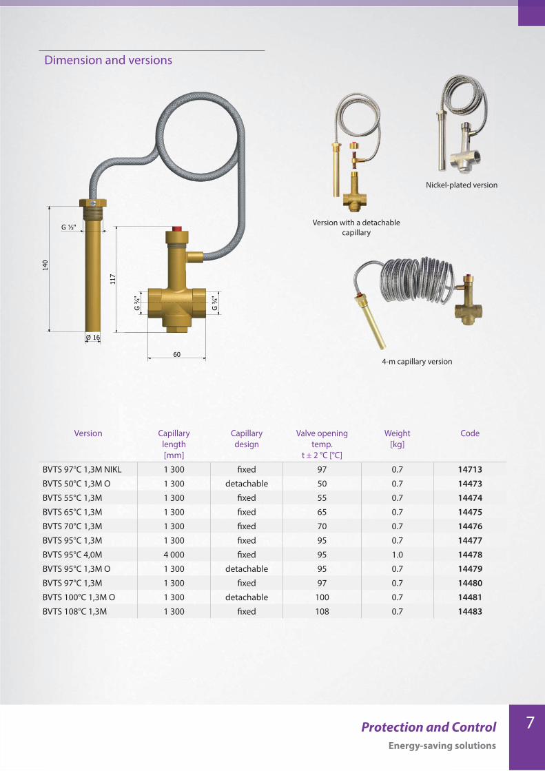
Thermostatic valve with a capillary designed for cooling sol-
id-fuel boilers with a cooling heat exchanger.
By opening a cold water inlet, the valve removes heat from
a boiler cooling heat exchanger, protecting the boiler from
overheating in case of emergency. Its opening temperature
depends on the valve version (the valve is factory set and
cannot be changed by the user).
In order to work properly, the valve sensor shall be installed
in a place where the highest temperature is reached in case
of overheating - usually directly in a top section of the boiler
or in an outlet pipe close to the boiler.
The valve has an activation push button for manual opening.
Functional tests are performed on each valve in production.
BVTS
Thermal Safety Relief Valves with capillary
Technical DataMAX. WORKING PRESSURE - HEATING WATER 6 bar
MAX. WORKING PRESSURE - COLD WATER 10 bar
CONNECTION THREAD G 3/4“ F
SENSOR SHEATH THREAD G 1/2“ M
The valve meets the requirements set by the Pressure
Equipment Directive (PED) 97/23/EC and EN 14597. It is
a STW device of Th type as defined by EN 14597, so it fulfils
the requirements for a device to dissipate excess heat, as of
Art. 4.3.8.4, EN 303-5.
BOILER PROTECTION AGAINST OVERHEATING
One-way Thermal Relief Valves
COLD
WATER
INLET
FLOW TO
HEATING
SYSTEM
RETURN
FROM
HEATING
SYSTEM
TO SEWER
7Protection and Control
Energy-saving solutions
Version with a detachable
capillary
Version Capillary
length
[mm]
Capillary
design
Valve opening
temp.
t ± 2 °C [°C]
Weight
[kg]
Code
BVTS 97°C 1,3M NIKL 1 300 fixed 97 0.7 14713
BVTS 50°C 1,3M O 1 300 detachable 50 0.7 14473
BVTS 55°C 1,3M 1 300 fixed 55 0.7 14474
BVTS 65°C 1,3M 1 300 fixed 65 0.7 14475
BVTS 70°C 1,3M 1 300 fixed 70 0.7 14476
BVTS 95°C 1,3M 1 300 fixed 95 0.7 14477
BVTS 95°C 4,0M 4 000 fixed 95 1.0 14478
BVTS 95°C 1,3M O 1 300 detachable 95 0.7 14479
BVTS 97°C 1,3M 1 300 fixed 97 0.7 14480
BVTS 100°C 1,3M O 1 300 detachable 100 0.7 14481
BVTS 108°C 1,3M 1 300 fixed 108 0.7 14483
Dimension and versions
4-m capillary version
Nickel-plated version
117
G ¾
"
60
G ¾
"
G ½"
Ø 16
140

8 Protection and Control
Energy-saving solutions
BOILER PROTECTION AGAINST OVERHEATING
Backup Power Supplies
NOMINAL VOLTAGE 230 V 50 Hz
INPUT VOLTAGE RANGE 170 - 260 V 50 Hz
OUTPUT WAVE FORM modified sine wave
OPERATING CONDITIONS0 - 40 °C,
non-condensing humidity
Model Power consumption
of the load
Backup time
PG 500 Compact20 W 5 h
45 W 3h 30 min
Technical data
PG500 Compact
Backup Power Supply with integrated batteries for circulation pumps
This Backup Power Supply comes with two mainte-
nance-free 12V, 9Ah batteries. Service life of the batteries
is about 5 years. The real service life depends on operating
conditions. Batteries are delivered charged, so they should
not be stored for more than 4 months after leaving Regu-
lus’s warehouse. They need to get charged after that period.
Backup power supply for circulation pumps or other
electric equipment during power cuts. It will provide power
supply for a boiler circulation pump, preventing the boiler
overheating.
Features
• Automatic switching from grid to battery and vice versa
• High efficiency inverter
• Smart two-step battery charging with overcharge
protection
• Protection from overload and complete battery
discharge
• Multi-function LED and sound signals
• No fan, thus very quiet operation
Models
Backup times
PG 500 Compact
NO. OF BATTERIES 2
BATTERY CAPACITY 18 Ah (2 x 9 Ah) / 12 V
MAX. INVERTER OUTPUT POWER 600 W
CODE 16214

9Protection and Control
Energy-saving solutions
BOILER PROTECTION AGAINST OVERHEATING
Backup Power Supplies
Technical data
Models
PG 500
Backup Power Supplies for circulation pumps
NOMINAL VOLTAGE 230 V 50 Hz
INPUT VOLTAGE RANGE 170 - 260 V 50 Hz
OUTPUT WAVE FORM modified sine wave
OPERATING CONDITIONS0 - 40 °C,
non-condensing humidity
NOISE LEVEL less than 45 dB
Backup Power Supplies come with special maintenance-free
batteries. Service life of the batteries is about 10 years. The
real service life depends on operating conditions. Batter-
ies are delivered charged, so they should not be stored for
more than 4 months after leaving Regulus’s warehouse.
They need to get charged after that period.
Backup power supply for circulation pumps or other electric
equipment during power cuts. It will provide power supply
for a boiler circulation pump, preventing the boiler over-
heating.
Features
• Automatic switching from grid to battery and vice versa
• High efficiency inverter
• Smart two-step battery charging with overcharge pro-
tection
• Protection from overload and complete battery dis-
charge
• Multi-function LED and sound signals
Model Power consumption
of the load
Backup time
PG 500-1820 W 6 h 30 min
45 W 3 h
PG 500-4465 W 5 h 48 min
100 W 3 h 42 min
PG 500-18 PG 500-44
NO. OF BATTERIES 1 1
BATTERY CAPACITY 18 Ah/12V 44 Ah/12V
MAX. INVERTER OUTPUT POWER 200 W 200 W
CODE 12505 9140
Backup times

10 Protection and Control
Energy-saving solutions
NOMINAL VOLTAGE 230 V, 50 Hz
INPUT VOLTAGE RANGE140 ~ 280 V +/- 5 %,
50 Hz +/- 5 Hz
OUTPUT WAVE FORM smooth sine wave
OPERATING CONDITIONS
0 - 40 °C,
non-condensing
humidity
NOISE LEVEL less than 60 dB
PG 600 S-18 PG 600 S-44 PG 600 S-100
NO. OF BATTERIES 1 1 1
BATTERY CAPACITY 18 Ah/12V 44 Ah/12V 100 Ah/12V
MAX. INVERTER OUTPUT POWER 600 W 600 W 600 W
CODE 17135 17136 17137
Model Power consumption
of the load
Backup time
PG 600 S-1820 W 3 h 11 min
45 W 2 h 02 min
PG 600 S-4465 W 3 h 35 min
100 W 2 h 26 min
PG 600 S-100120 W 4 h 37 min
250 W 2 h 31 min
BOILER PROTECTION AGAINST OVERHEATING
Backup Power Supplies
Technical data
PG 600 S
Backup Power Supplies for circulation pumps, smooth output sine wave
Backup Power Supplies come with special maintenance-free
batteries. Service life of the batteries is about 10 years. The
real service life depends on operating conditions. Batter-
ies are delivered charged, so they should not be stored for
more than 4 months after leaving Regulus‘s warehouse.
They need to get charged after that period.
Backup power supply for circulation pumps or other
electric equipment during power cuts. It will provide power
supply for a boiler circulation pump, preventing the boiler
overheating.
Features
• Automatic switching from grid to battery and vice versa,
adjustable charging current
• High efficiency inverter
• Smart three-step battery charging with overcharge
protection
• Protection from overload and complete battery
discharge, possibility to set the minimum battery
voltage for power supply is disconnection
• LCD display
• Internal temperature controlled fan
• Smooth output sine wave
Models
Backup times

11Protection and Control
Energy-saving solutions
12 Protection and Control
Energy-saving solutions
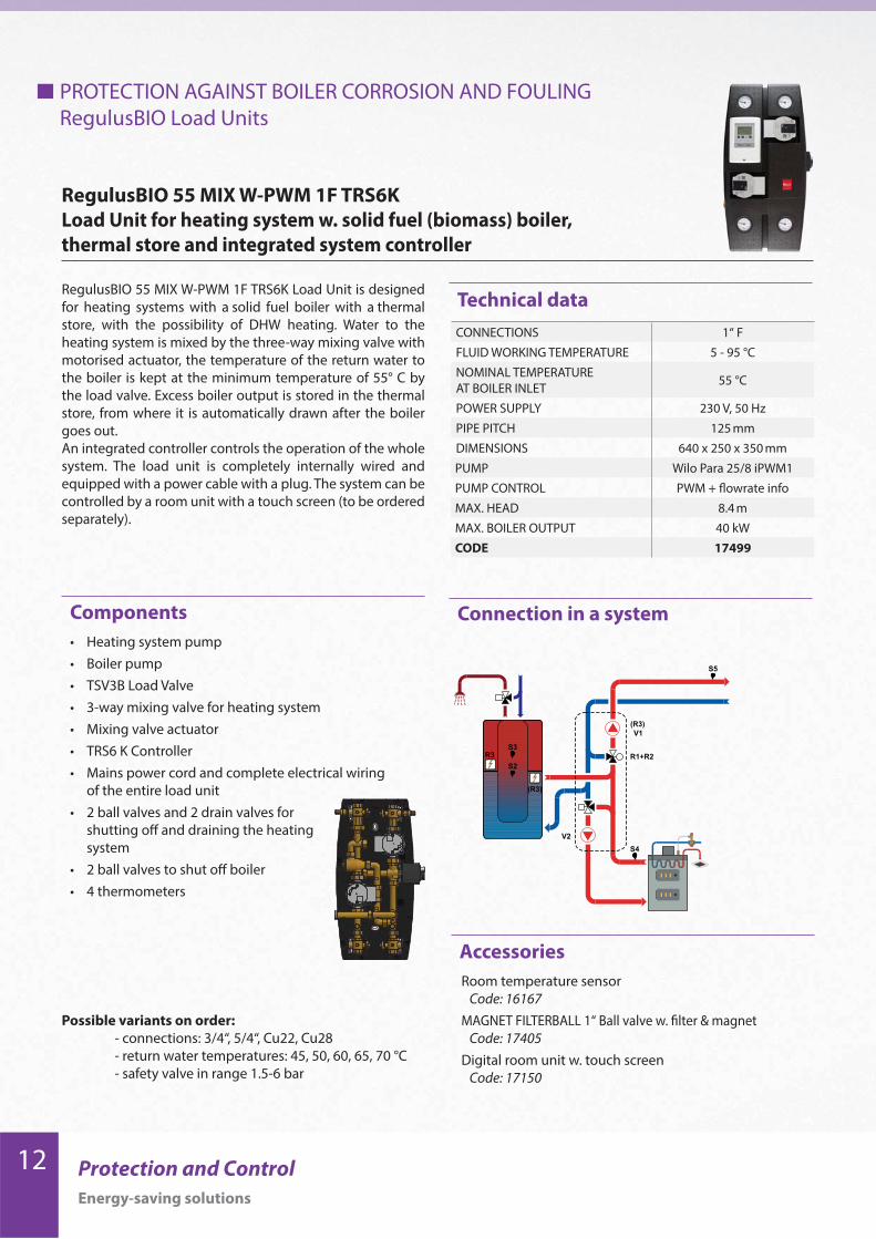
RegulusBIO 55 MIX W-PWM 1F TRS6K
Load Unit for heating system w. solid fuel (biomass) boiler,
thermal store and integrated system controller
RegulusBIO 55 MIX W-PWM 1F TRS6K Load Unit is designed
for heating systems with a solid fuel boiler with a thermal
store, with the possibility of DHW heating. Water to the
heating system is mixed by the three-way mixing valve with
motorised actuator, the temperature of the return water to
the boiler is kept at the minimum temperature of 55° C by
the load valve. Excess boiler output is stored in the thermal
store, from where it is automatically drawn after the boiler
goes out.
An integrated controller controls the operation of the whole
system. The load unit is completely internally wired and
equipped with a power cable with a plug. The system can be
controlled by a room unit with a touch screen (to be ordered
separately).
Connection in a system
Technical data
• Heating system pump
• Boiler pump
• TSV3B Load Valve
• 3-way mixing valve for heating system
• Mixing valve actuator
• TRS6 K Controller
• Mains power cord and complete electrical wiring
of the entire load unit
• 2 ball valves and 2 drain valves for
shutting off and draining the heating
system
• 2 ball valves to shut off boiler
• 4 thermometers
Room temperature sensor
Code: 16167
MAGNET FILTERBALL 1“ Ball valve w. filter & magnet
Code: 17405
Digital room unit w. touch screen
Code: 17150
Components
Accessories
Possible variants on order:
- connections: 3/4“, 5/4“, Cu22, Cu28
- return water temperatures: 45, 50, 60, 65, 70 °C
- safety valve in range 1.5-6 bar
PROTECTION AGAINST BOILER CORROSION AND FOULING
RegulusBIO Load Units
CONNECTIONS 1“ F
FLUID WORKING TEMPERATURE 5 - 95 °C
NOMINAL TEMPERATURE
AT BOILER INLET55 °C
POWER SUPPLY 230 V, 50 Hz
PIPE PITCH 125 mm
DIMENSIONS 640 x 250 x 350 mm
PUMP Wilo Para 25/8 iPWM1
PUMP CONTROL PWM + flowrate info
MAX. HEAD 8.4 m
MAX. BOILER OUTPUT 40 kW
CODE 17499
13Protection and Control
Energy-saving solutions
Connection in a system
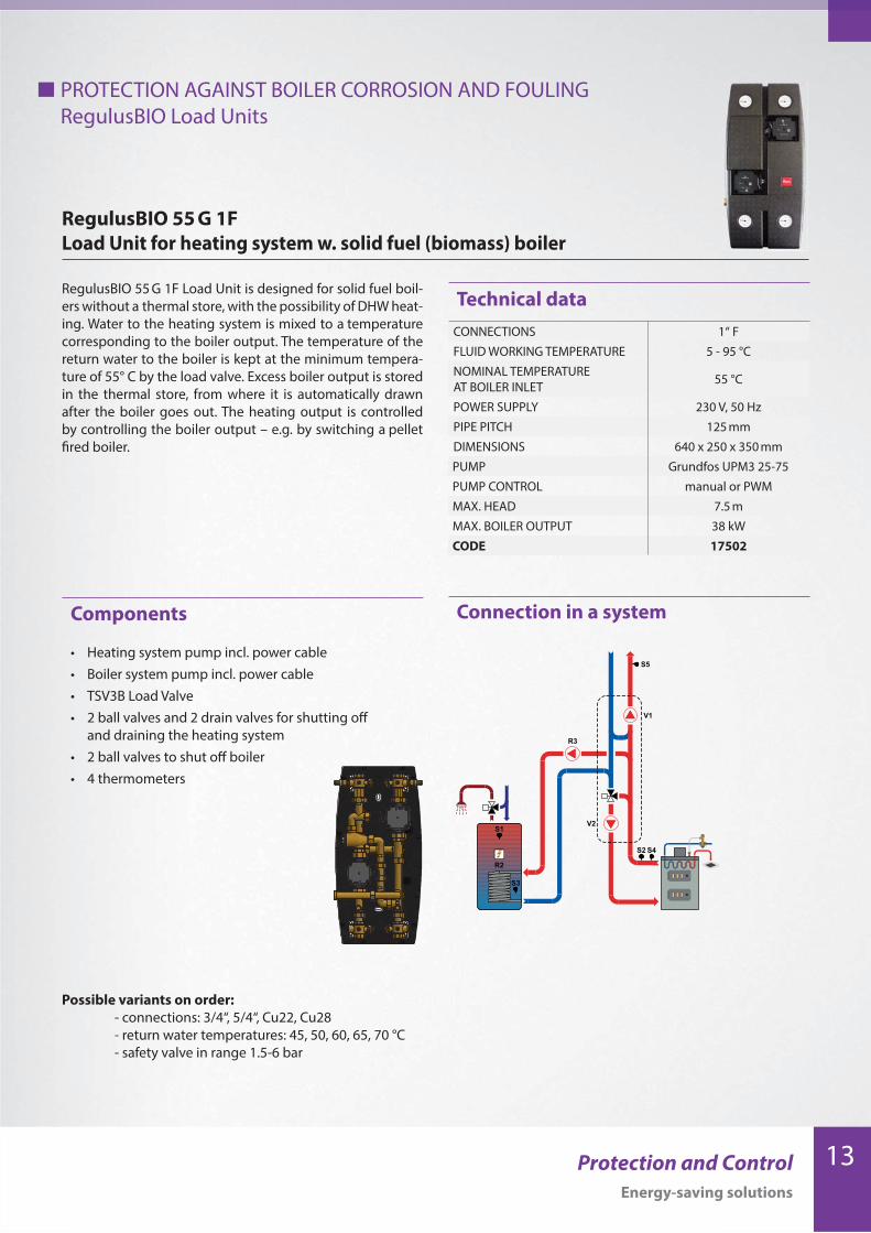
RegulusBIO 55 G 1F
Load Unit for heating system w. solid fuel (biomass) boiler
RegulusBIO 55 G 1F Load Unit is designed for solid fuel boil-
ers without a thermal store, with the possibility of DHW heat-
ing. Water to the heating system is mixed to a temperature
corresponding to the boiler output. The temperature of the
return water to the boiler is kept at the minimum tempera-
ture of 55° C by the load valve. Excess boiler output is stored
in the thermal store, from where it is automatically drawn
after the boiler goes out. The heating output is controlled
by controlling the boiler output – e.g. by switching a pellet
fired boiler.
• Heating system pump incl. power cable
• Boiler system pump incl. power cable
• TSV3B Load Valve
• 2 ball valves and 2 drain valves for shutting off
and draining the heating system
• 2 ball valves to shut off boiler
• 4 thermometers
Components
Technical data
Possible variants on order:
- connections: 3/4“, 5/4“, Cu22, Cu28
- return water temperatures: 45, 50, 60, 65, 70 °C
- safety valve in range 1.5-6 bar
PROTECTION AGAINST BOILER CORROSION AND FOULING
RegulusBIO Load Units
CONNECTIONS 1“ F
FLUID WORKING TEMPERATURE 5 - 95 °C
NOMINAL TEMPERATURE
AT BOILER INLET55 °C
POWER SUPPLY 230 V, 50 Hz
PIPE PITCH 125 mm
DIMENSIONS 640 x 250 x 350 mm
PUMP Grundfos UPM3 25-75
PUMP CONTROL manual or PWM
MAX. HEAD 7.5 m
MAX. BOILER OUTPUT 38 kW
CODE 17502
14 Protection and Control
Energy-saving solutions
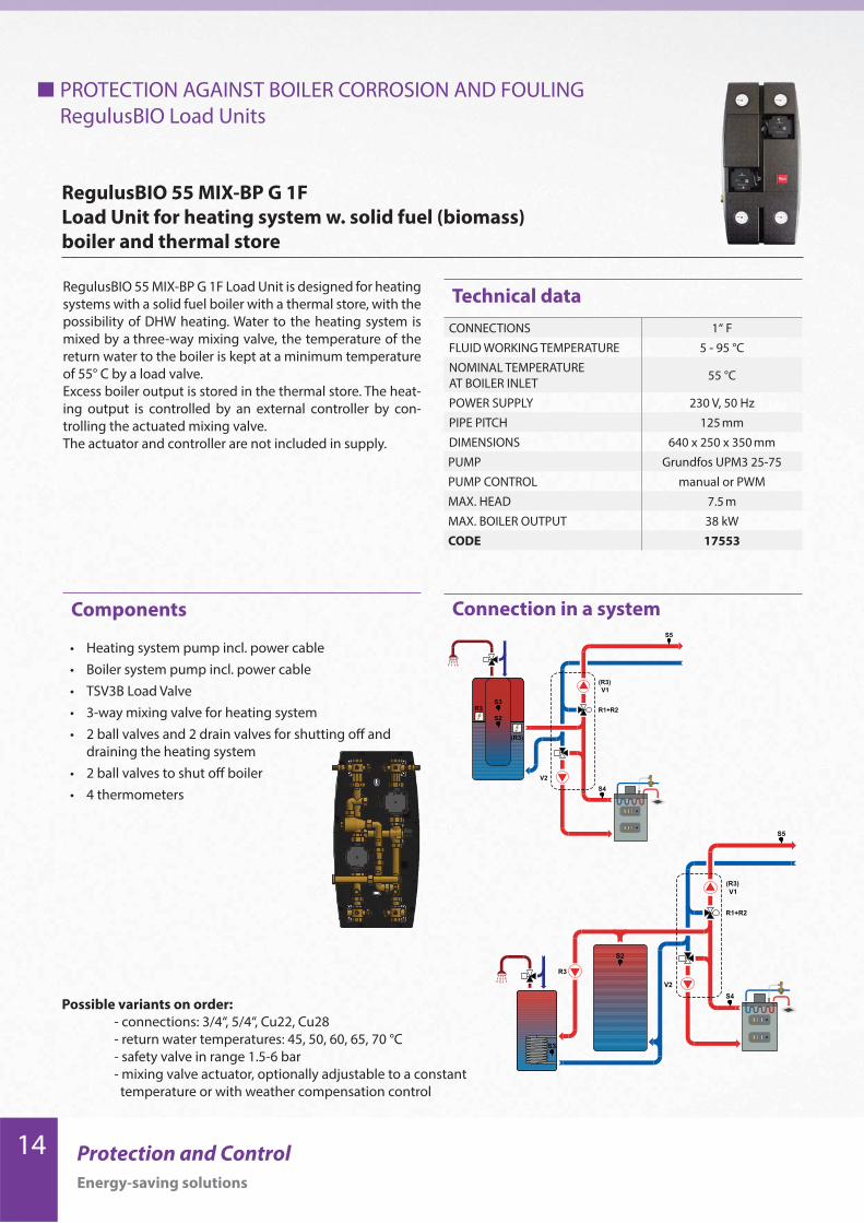
RegulusBIO 55 MIX-BP G 1F
Load Unit for heating system w. solid fuel (biomass)
boiler and thermal store
RegulusBIO 55 MIX-BP G 1F Load Unit is designed for heating
systems with a solid fuel boiler with a thermal store, with the
possibility of DHW heating. Water to the heating system is
mixed by a three-way mixing valve, the temperature of the
return water to the boiler is kept at a minimum temperature
of 55° C by a load valve.
Excess boiler output is stored in the thermal store. The heat-
ing output is controlled by an external controller by con-
trolling the actuated mixing valve.
The actuator and controller are not included in supply.
Connection in a system
• Heating system pump incl. power cable
• Boiler system pump incl. power cable
• TSV3B Load Valve
• 3-way mixing valve for heating system
• 2 ball valves and 2 drain valves for shutting off and
draining the heating system
• 2 ball valves to shut off boiler
• 4 thermometers
Components
Technical data
Possible variants on order:
- connections: 3/4“, 5/4“, Cu22, Cu28
- return water temperatures: 45, 50, 60, 65, 70 °C
- safety valve in range 1.5-6 bar
- mixing valve actuator, optionally adjustable to a constant
temperature or with weather compensation control
PROTECTION AGAINST BOILER CORROSION AND FOULING
RegulusBIO Load Units
CONNECTIONS 1“ F
FLUID WORKING TEMPERATURE 5 - 95 °C
NOMINAL TEMPERATURE
AT BOILER INLET55 °C
POWER SUPPLY 230 V, 50 Hz
PIPE PITCH 125 mm
DIMENSIONS 640 x 250 x 350 mm
PUMP Grundfos UPM3 25-75
PUMP CONTROL manual or PWM
MAX. HEAD 7.5 m
MAX. BOILER OUTPUT 38 kW
CODE 17553

15Protection and Control
Energy-saving solutions
16 Protection and Control
Energy-saving solutions
PROTECTION AGAINST BOILER CORROSION AND FOULING
RegulusRGMAT Load Units
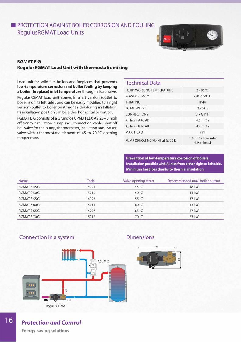
RGMAT E G
RegulusRGMAT Load Unit with thermostatic mixing
FLUID WORKING TEMPERATURE 2 - 95 °C
POWER SUPPLY 230 V, 50 Hz
IP RATING IP44
TOTAL WEIGHT 3.25 kg
CONNECTIONS 3 x G1“ F
Kvs
from A to AB 6.2 m3/h
Kvs
from B to AB 4.4 m3/h
MAX. HEAD 7 m
PUMP OPERATING POINT at Δt 20 K 1.8 m3/h flow rate
4.9 m head
Load unit for solid-fuel boilers and fireplaces that prevents
low-temperature corrosion and boiler fouling by keeping
a boiler (fireplace) inlet temperature through a load valve.
RegulusRGMAT load unit comes in a left version (outlet to
boiler is on its left side), and can be easily modified to a right
version (outlet to boiler on its right side) during installation.
Its installation position can be either horizontal or vertical.
RGMAT E G consists of a Grundfos UPM3 FLEX AS 25-70 high
efficiency circulation pump incl. connection cable, shut-off
ball valve for the pump, thermometer, insulation and TSV3BF
valve with a thermostatic element of 45 to 70 °C opening
temperature.
Prevention of low-temperature corrosion of boilers.
Installation possible with A inlet from either right or left side.
Minimum heat loss thanks to thermal insulation.
Technical Data
Connection in a system Dimensions
Name Code Valve opening temp. Recommended max. boiler output
RGMAT E 45 G 14925 45 °C 48 kW
RGMAT E 50 G 15910 50 °C 44 kW
RGMAT E 55 G 14926 55 °C 37 kW
RGMAT E 60 G 15911 60 °C 33 kW
RGMAT E 65 G 14927 65 °C 27 kW
RGMAT E 70 G 15912 70 °C 23 kW
CSE MIX
RegulusRGMAT
17Protection and Control
Energy-saving solutions
PROTECTION AGAINST BOILER CORROSION AND FOULING
RegulusRGMAT Load Units
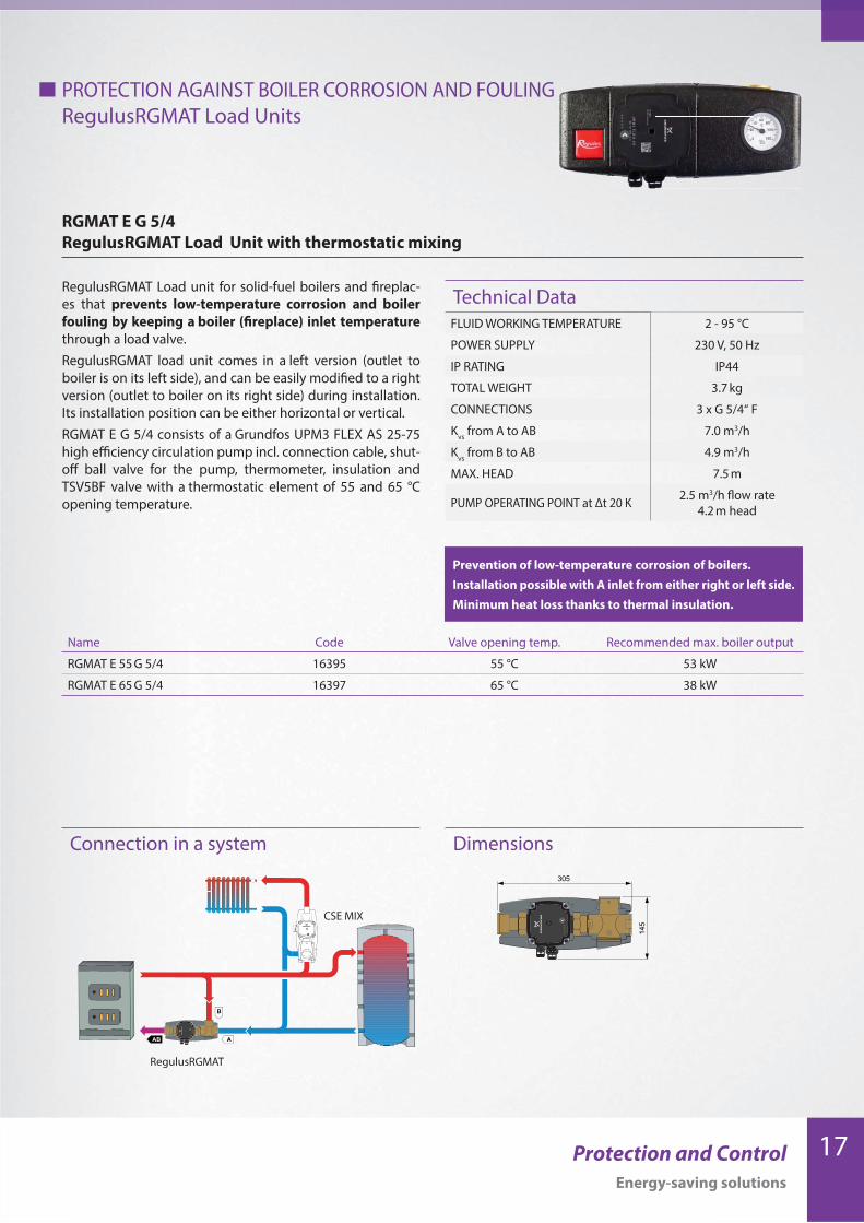
RGMAT E G 5/4
RegulusRGMAT Load Unit with thermostatic mixing
RegulusRGMAT Load unit for solid-fuel boilers and fireplac-
es that prevents low-temperature corrosion and boiler
fouling by keeping a boiler (fireplace) inlet temperature
through a load valve.
RegulusRGMAT load unit comes in a left version (outlet to
boiler is on its left side), and can be easily modified to a right
version (outlet to boiler on its right side) during installation.
Its installation position can be either horizontal or vertical.
RGMAT E G 5/4 consists of a Grundfos UPM3 FLEX AS 25-75
high efficiency circulation pump incl. connection cable, shut-
off ball valve for the pump, thermometer, insulation and
TSV5BF valve with a thermostatic element of 55 and 65 °C
opening temperature.
FLUID WORKING TEMPERATURE 2 - 95 °C
POWER SUPPLY 230 V, 50 Hz
IP RATING IP44
TOTAL WEIGHT 3.7 kg
CONNECTIONS 3 x G 5/4“ F
Kvs
from A to AB 7.0 m3/h
Kvs
from B to AB 4.9 m3/h
MAX. HEAD 7.5 m
PUMP OPERATING POINT at Δt 20 K 2.5 m3/h flow rate
4.2 m head
Prevention of low-temperature corrosion of boilers.
Installation possible with A inlet from either right or left side.
Minimum heat loss thanks to thermal insulation.
Technical Data
Dimensions
Name Code Valve opening temp. Recommended max. boiler output
RGMAT E 55 G 5/4 16395 55 °C 53 kW
RGMAT E 65 G 5/4 16397 65 °C 38 kW
Connection in a system
CSE MIX
RegulusRGMAT

18 Protection and Control
Energy-saving solutions
PROTECTION AGAINST BOILER CORROSION AND FOULING
RegulusRGMAT Load Units
RGMAT E W
RegulusRGMAT Load Unit with thermostatic mixing
RegulusRGMAT Load unit for solid-fuel boilers and fireplac-
es that prevents low-temperature corrosion and boiler
fouling by keeping a boiler (fireplace) inlet temperature
through a load valve.
RegulusRGMAT load unit comes in a left version (outlet to
boiler is on its left side), and can be easily modified to a right
version (outlet to boiler on its right side) during installation.
Its installation position can be either horizontal or vertical.
RGMAT E W consists of a Wilo Yonos Para RS25/7,5 high effi-
ciency circulation pump incl. connection cable, shut-off ball
valve for the pump, thermometer, insulation and TSV5BF
valve with a thermostatic element of 45 to 70°C opening
temperature.
FLUID WORKING TEMPERATURE 2 - 95 °C
POWER SUPPLY 230 V, 50 Hz
IP RATING IP44
TOTAL WEIGHT 3.3 kg
CONNECTIONS 3 x G1“ F
Kvs
from A to AB 6.2 m3/h
Kvs
from B to AB 4.4 m3/h
MAX. HEAD 7.6 m
PUMP OPERATING POINT at Δt 20 K 2.7 m3/h flow rate
4.9 m head
Prevention of low-temperature corrosion of boilers.
Installation possible with A inlet from either right or left side.
Minimum heat loss thanks to thermal insulation.
Technical Data
Connection in a system Dimensions
Name Code Valve opening temp. Recommended max. boiler output
RGMAT E 45 W 15867 45 °C 45 kW
RGMAT E 50 W 15904 50 °C 42 kW
RGMAT E 55 W 15868 55 °C 36 kW
RGMAT E 60 W 15905 60 °C 32 kW
RGMAT E 65 W 15869 65 °C 26 kW
RGMAT E 70 W 15906 70 °C 22 kW
Also available with PARA 25/8 iPWM1 pump
controlled by PWM signal
- code: 18133 - 55°C, 18131 - 65 °C.
Wilo YONOS PARA pumps will be gradually replaced by the Wilo PARA model.
CSE MIX
RegulusRGMAT

19Protection and Control
Energy-saving solutions
Also available with PARA 25/8 iPWM1 pump
controlled by PWM signal
- code: 18132 - 55°C, 18129 - 65 °C
PROTECTION AGAINST BOILER CORROSION AND FOULING
RegulusRGMAT Load Units
RGMAT E W 5/4
RegulusRGMAT Load Unit with thermostatic mixing
RegulusRGMAT Load unit for solid-fuel boilers and fireplac-
es that prevents low-temperature corrosion and boiler
fouling by keeping a boiler (fireplace) inlet temperature
through a load valve.
RegulusRGMAT load unit comes in a left version (outlet to
boiler is on its left side), and can be easily modified to a right
version (outlet to boiler on its right side) during installation.
Its installation position can be either horizontal or vertical.
RGMAT E W 5/4 consists of a Wilo Yonos Para RS25/7,5 high
efficiency circulation pump incl. connection cable, thermom-
eter, insulation and TSV5B valve with a thermostatic element
of 55 and 65°C opening temperature.
FLUID WORKING TEMPERATURE 2 - 95 °C
POWER SUPPLY 230 V, 50 Hz
IP RATING IP44
TOTAL WEIGHT 3.7 kg
CONNECTIONS 3 x G5/4“ F
Kvs
from A to AB 7.0 m3/h
Kvs
from B to AB 4.9 m3/h
MAX. HEAD 7.6 m
PUMP OPERATING POINT at Δt 20 K 2.7 m3/h flow rate
4.9 m head
Prevention of low-temperature corrosion of boilers.
Installation possible with A inlet from either right or left side.
Minimum heat loss thanks to thermal insulation.
Technical Data
Connection in a system Dimensions
Name Code Valve opening temp. Recommended max. boiler output
RGMAT E 55 W 5/4 15790 55 °C 57 kW
RGMAT E 65 W 5/4 15791 65 °C 41 kW
CSE MIX
RegulusRGMAT
Wilo YONOS PARA pumps will be gradually replaced by the Wilo PARA model.

20 Protection and Control
Energy-saving solutions
PROTECTION AGAINST BOILER CORROSION AND FOULING
RegulusRGMAT Load Units
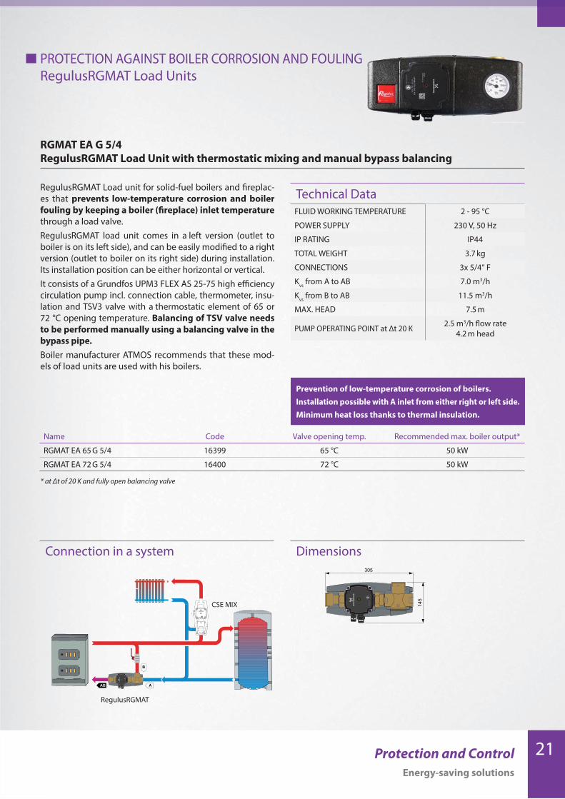
RGMAT EA G
RegulusRGMAT Load Unit with thermostatic mixing and manual bypass balancing
RegulusRGMAT Load unit for solid-fuel boilers and fireplac-
es that prevents low-temperature corrosion and boiler
fouling by keeping a boiler (fireplace) inlet temperature
through a load valve.
RegulusRGMAT load unit comes in a left version (outlet to
boiler is on its left side), and can be easily modified to a right
version (outlet to boiler on its right side) during installation.
Its installation position can be either horizontal or vertical.
RGMAT EA G consists of a Grundfos UPM3 FLEX AS 25-70 high
efficiency circulation pump incl. connection cable, shut-off
ball valve for the pump, thermometer, insulation and TSV5
valve with a thermostatic element of 65 or 72°C opening tem-
perature. Balancing of TSV valve needs to be performed
manually using a balancing valve in the bypass pipe.
Boiler manufacturer ATMOS recommends that these mod-
els of load units are used with his boilers.
FLUID WORKING TEMPERATURE 2 - 95 °C
POWER SUPPLY 230 V, 50 Hz
IP RATING IP44
TOTAL WEIGHT 3.25 kg
CONNECTIONS 3x 1“ F
Kvs
from A to AB 6.2 m3/h
Kvs
from B to AB 10.1 m3/h
MAX. HEAD 7 m
PUMP OPERATING POINT at Δt 20 K 1.8 m3/h flow rate
4.9 m head
Prevention of low-temperature corrosion of boilers.
Installation possible with A inlet from either right or left side.
Minimum heat loss thanks to thermal insulation.
Technical Data
Connection in a system Dimensions
Name Code Valve opening temp. Recommended max. boiler output*
RGMAT EA 65 G 16383 65 °C 25 kW
RGMAT EA 72 G 16384 72 °C 25 kW
* at Δt of 20 K and fully open balancing valve
CSE MIX
RegulusRGMAT
21Protection and Control
Energy-saving solutions
Prevention of low-temperature corrosion of boilers.
Installation possible with A inlet from either right or left side.
Minimum heat loss thanks to thermal insulation.
Name Code Valve opening temp. Recommended max. boiler output*
RGMAT EA 65 G 5/4 16399 65 °C 50 kW
RGMAT EA 72 G 5/4 16400 72 °C 50 kW
* at Δt of 20 K and fully open balancing valve
PROTECTION AGAINST BOILER CORROSION AND FOULING
RegulusRGMAT Load Units
RGMAT EA G 5/4
RegulusRGMAT Load Unit with thermostatic mixing and manual bypass balancing
RegulusRGMAT Load unit for solid-fuel boilers and fireplac-
es that prevents low-temperature corrosion and boiler
fouling by keeping a boiler (fireplace) inlet temperature
through a load valve.
RegulusRGMAT load unit comes in a left version (outlet to
boiler is on its left side), and can be easily modified to a right
version (outlet to boiler on its right side) during installation.
Its installation position can be either horizontal or vertical.
It consists of a Grundfos UPM3 FLEX AS 25-75 high efficiency
circulation pump incl. connection cable, thermometer, insu-
lation and TSV3 valve with a thermostatic element of 65 or
72 °C opening temperature. Balancing of TSV valve needs
to be performed manually using a balancing valve in the
bypass pipe.
Boiler manufacturer ATMOS recommends that these mod-
els of load units are used with his boilers.
FLUID WORKING TEMPERATURE 2 - 95 °C
POWER SUPPLY 230 V, 50 Hz
IP RATING IP44
TOTAL WEIGHT 3.7 kg
CONNECTIONS 3x 5/4“ F
Kvs
from A to AB 7.0 m3/h
Kvs
from B to AB 11.5 m3/h
MAX. HEAD 7.5 m
PUMP OPERATING POINT at Δt 20 K 2.5 m3/h flow rate
4.2 m head
Technical Data
Connection in a system Dimensions
CSE MIX
RegulusRGMAT

22 Protection and Control
Energy-saving solutions
PROTECTION AGAINST BOILER CORROSION AND FOULING
RegulusRGMAT Load Units
RGMAT EA W
RegulusRGMAT Load Unit with thermostatic mixing and manual bypass balancing
RegulusRGMAT Load unit for solid-fuel boilers and fireplac-
es that prevents low-temperature corrosion and boiler
fouling by keeping a boiler (fireplace) inlet temperature
through a load valve.
RegulusRGMAT load unit comes in a left version (outlet to
boiler is on its left side), and can be easily modified to a right
version (outlet to boiler on its right side) during installation.
Its installation position can be either horizontal or vertical.
RGMAT EA W consists of a Wilo Yonos Para RS25/7,5 high effi-
ciency circulation pump incl. connection cable, shut-off ball
valve for the pump, thermometer, insulation and TSV3 valve
with a thermostatic element of 65 or 72°C opening tempera-
ture. Balancing of TSV valve needs to be performed man-
ually using a balancing valve in the bypass pipe.
Boiler manufacturer ATMOS recommends that these mod-
els of load units are used with his boilers.
* at Δt of 20 K and fully open balancing valve
FLUID WORKING TEMPERATURE 2 - 95 °C
POWER SUPPLY 230 V, 50 Hz
IP RATING IP44
TOTAL WEIGHT 3.6 kg
CONNECTIONS 3x 1“ F
Kvs
from A to AB 6.2 m3/h
Kvs
from B to AB 10.1 m3/h
MAX. HEAD 7.6 m
PUMP OPERATING POINT at Δt 20 K 2.7 m3/h flow rate
4.9 m head
Prevention of low-temperature corrosion of boilers.
Installation possible with A inlet from either right or left side.
Minimum heat loss thanks to thermal insulation.
Technical Data
Connection in a system Dimensions
Name Code Valve opening temp. Recommended max. boiler output*
RGMAT EA 65 W 16036 65 °C 25 kW
RGMAT EA 72 W 16031 72 °C 25 kW
CSE MIX
RegulusRGMAT
Wilo YONOS PARA pumps will be gradually replaced by the Wilo PARA model.

23Protection and Control
Energy-saving solutions
PROTECTION AGAINST BOILER CORROSION AND FOULING
RegulusRGMAT Load Units
RGMAT EA W 5/4
RegulusRGMAT Load Unit with thermostatic mixing and manual bypass balancing
RegulusRGMAT Load unit for solid-fuel boilers and fireplac-
es that prevents low-temperature corrosion and boiler
fouling by keeping a boiler (fireplace) inlet temperature
through a load valve.
RegulusRGMAT load unit comes in a left version (outlet to
boiler is on its left side), and can be easily modified to a right
version (outlet to boiler on its right side) during installation.
Its installation position can be either horizontal or vertical.
RGMAT EA W 5/4 consists of a Wilo Yonos Para RS25/7,5 high
efficiency circulation pump incl. connection cable, shut-off
ball valve for the pump, thermometer, insulation and TSV5
valve with a thermostatic element of 65 or 72°C opening tem-
perature. Balancing of TSV valve needs to be performed
manually using a balancing valve in the bypass pipe.
Boiler manufacturer ATMOS recommends that these mod-
els of load units are used with his boilers.
* at Δt of 20 K and fully open balancing valve
FLUID WORKING TEMPERATURE 2 - 95 °C
POWER SUPPLY 230 V, 50 Hz
IP RATING IP44
TOTAL WEIGHT 3.3 kg
CONNECTIONS 3x 5/4“
Kvs
from A to AB 7.0 m3/h
Kvs
from B to AB 11.5 m3/h
MAX. HEAD 7.6 m
PUMP OPERATING POINT at Δt 20 K 3.3 m3/h flow rate
3.8 m head
Prevention of low-temperature corrosion of boilers.
Installation possible with A inlet from either right or left side.
Minimum heat loss thanks to thermal insulation.
Technical Data
Connection in a system Dimensions
Name Code Valve opening temp. Recommended max. boiler output*
RGMAT EA 65 W 5/4 16037 65 °C 50 kW
RGMAT EA 72 W 5/4 16032 72 °C 50 kW
CSE MIX
RegulusRGMAT
Wilo YONOS PARA pumps will be gradually replaced by the Wilo PARA model.

24 Protection and Control
Energy-saving solutions
PROTECTION AGAINST BOILER CORROSION AND FOULING
Accessories for RegulusRGMAT Load Units
BP RGMAT
Bypass with floating non-return valve
RegulusRGMAT Load units can be amended with a bypass with a floating non-return valve.
In case of a power failure or a broken circulation pump the boiler will cool down into the thermal store via gravity circulation
through the bypass a with non-return valve.
Versions
Name Code
By-pass with a non-return valve
for RGMAT with 1” connections16126
By-pass with a non-return valve
for RGMAT with 5/4”
connections
16139
Connection in a system

25Protection and Control
Energy-saving solutions
Version LK810 - 55 LK810 - 65 LK810 - 72
Min. temper. of
return to boiler55 °C 65 °C 72 °C
Recommended
max. boiler output56 kW 45 kW 41 kW
Code 15046 15047 16244
PROTECTION AGAINST BOILER CORROSION AND FOULING
ThermoMat Load Units
Connection in a system
Dimensions
Versions
ThermoMat
Load Unit with with thermostatic mixing and floating non-return valve
The load unit consists of:
Grundfos UPM3 AUTO L Circulation pump
Load valve
By-pass w. automatic balancing
Floating non-return valve
3 thermometers
3 5/4“ ball valves with union nuts
Neat insulation for low heat loss
ThermoMat ECO+ LK 810 Load Unit mixes cool return wa-
ter from a heating system (or thermal store) with hot water
from a boiler flow, keeping boiler return water temperature
at a given min. temperature (55°C, 65°C, 72°C, depending on
the type).
The floating nor-return valve permits boiler cooling through
gravity circulation in case of a power failure or a circulation
pump breakdown.
Technical DataFLUID WORKING TEMPERATURE 2 - 110 °C
MAX. WORKING PRESSURE 10 bar
POWER SUPPLY 230 V, 50 Hz
IP RATING IP44
TOTAL WEIGHT 3.45 kg
CONNECTION 3 x G5/4“ F
PUMP OPERATING POINT at Δt 20 K 1.9 m3/h flow rate
4.6 m head
A
B
AB
G 5/
4"
G 5/
4"
G 5/4"
195
196
258
204
82
CSE MIX
LK810
26 Protection and Control
Energy-saving solutions
PROTECTION AGAINST BOILER CORROSION AND FOULING
RegulusTOP Load Units
Connection in a system
Dimensions
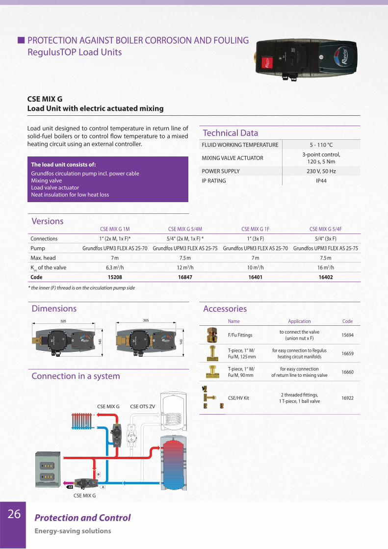
CSE MIX G
Load Unit with electric actuated mixing
The load unit consists of:
Grundfos circulation pump incl. power cable
Mixing valve
Load valve actuator
Neat insulation for low heat loss
Load unit designed to control temperature in return line of
solid-fuel boilers or to control flow temperature to a mixed
heating circuit using an external controller.
Technical DataFLUID WORKING TEMPERATURE 5 - 110 °C
MIXING VALVE ACTUATOR3-point control,
120 s, 5 Nm
POWER SUPPLY 230 V, 50 Hz
IP RATING IP44
VersionsCSE MIX G 1M CSE MIX G 5/4M CSE MIX G 1F CSE MIX G 5/4F
Connections 1“ (2x M, 1x F)* 5/4“ (2x M, 1x F) * 1“ (3x F) 5/4“ (3x F)
Pump Grundfos UPM3 FLEX AS 25-70 Grundfos UPM3 FLEX AS 25-75 Grundfos UPM3 FLEX AS 25-70 Grundfos UPM3 FLEX AS 25-75
Max. head 7 m 7.5 m 7 m 7.5 m
Kvs
of the valve 6.3 m3/h 12 m3/h 10 m3/h 16 m3/h
Code 15208 16847 16401 16402
Name Application Code
F/Fu Fittings to connect the valve
(union nut x F)15694
T-piece, 1“ M/
Fu/M, 125 mm
for easy connection to Regulus
heating circuit manifolds16659
T-piece, 1“ M/
Fu/M, 90 mm
for easy connection
of return line to mixing valve16660
CSE/HV Kit2 threaded fittings,
1 T-piece, 1 ball valve16922
Accessories
* the inner (F) thread is on the circulation pump side
CSE OTS ZV CSE MIX G
CSE MIX G

27Protection and Control
Energy-saving solutions
PROTECTION AGAINST BOILER CORROSION AND FOULING
RegulusTOP Load Units
Connection in a system
Dimensions
CSE MIX W
Load Unit with electric actuated mixing
The load unit consists of:
Wilo Circulation pump incl. power cable
Mixing valve
Mixing valve actuator
Neat insulation for low heat loss
Load unit designed to control temperature in return line of
solid-fuel boilers or to control flow temperature to a mixed
heating circuit using an external controller.
Technical DataFLUID WORKING TEMPERATURE 5 - 110 °C
MIXING VALVE ACTUATOR3-point control,
120 s, 5 Nm
POWER SUPPLY 230 V, 50 Hz
IP RATING IP44
Versions
* the inner (F) thread is on the circulation pump side
CSE OTS ZV CSE MIX W
CSE MIX W
Wilo YONOS PARA pumps will be gradually replaced by the
Wilo PARA model.
CSE MIX W -SC 1M CSE MIX W 5/4M CSE MIX W 1F CSE MIX W-PWM 1F CSE MIX W 5/4F CSE MIX W-PWM 5/4F
Connections 1“ (2x M, 1x F)* 5/4“ (2x M, 1x F) * 1“ (3x F) 1“ (3x F) 5/4“ (3x F) 1“ (3x F)
Wilo pump PARA 25/8 SC YP RS25/7.5 YP RS25/7.5 PARA 25/8 iPWM1 YP RS25/7.5 PARA 25/8 iPWM1
Pump control manual manual manual PWM + flowrate info manual PWM + flowrate info
Max. head 8.4 m 7.6 m 7.6 m 8.4 m 7.6 m 8.4 m
Kvs
of the mixing valve 6.3 m3/h 12 m3/h 10 m3/h 10 m3/h 16 m3/h 16 m3/h
Code 17980 16848 16219 18128 16215 18130
Name Application Code
F/Fu Fittings to connect the valve
(union nut x F)15694
T-piece, 1“ M/
Fu/M, 125 mm
for easy connection to Regulus
heating circuit manifolds16659
T-piece, 1“ M/
Fu/M, 90 mm
for easy connection
of return line to mixing valve16660
CSE/HV Kit2 threaded fittings,
1 T-piece, 1 ball valve16922
Accessories

28 Protection and Control
Energy-saving solutions
PROTECTION AGAINST BOILER CORROSION AND FOULING
RegulusTOP Load Units
Connection in a system
CSE MIX FIX G
Load Unit with electronic controlled mixing
The load unit consists of:
Grundfos Circulation pump incl. power cable
Mixing valve
Mixing valve actuator with electronics
Pt1000 temperature sensors – 2 pieces
Neat insulation for low heat loss
Load unit designed to control the return temperature of sol-
id fuel boilers or to control the flow temperature of mixed
heating circuits to a fixed temperature, adjustable directly
on the actuator, between 0 and 99°C.
Technical Data
Dimensions
VersionsCSE MIX FIX G 1M CSE MIX FIX G 5/4M CSE MIX FIX G 1F CSE MIX FIX G 5/4F
Connections 1“ (2x M, 1x F)* 5/4“ (2x M, 1x F)* 1“ (3x F) 5/4“ (3x F)
Pump Grundfos UPM3 FLEX AS 25-70 Grundfos UPM3 FLEX AS 25-75 Grundfos UPM3 FLEX AS 25-70 Grundfos UPM3 FLEX AS 25-75
Max. head 7 m 7.5 m 7 m 7.5 m
Kvs
of the valve 6.3 m3/h 12 m3/h 10 m3/h 16 m3/h
Code 15333 16844 16403 16404
FLUID WORKING TEMPERATURE 5 - 110 °C
MIXING VALVE ACTUATORcontrol to a fixed temp.,
120 s, 6 Nm
POWER SUPPLY 230 V, 50 Hz
IP RATING IP44
* the inner (F) thread is on the circulation pump side
CSE OTS ZV CSE MIX G
CSE MIX FIX G
Name Application Code
F/Fu Fittings to connect the valve
(union nut x F)15694
T-piece, 1“ M/
Fu/M, 125 mm
for easy connection to Regulus
heating circuit manifolds16659
T-piece, 1“ M/
Fu/M, 90 mm
for easy connection
of return line to mixing valve16660
CSE/HV Kit2 threaded fittings,
1 T-piece, 1 ball valve16922
Accessories

29Protection and Control
Energy-saving solutions
PROTECTION AGAINST BOILER CORROSION AND FOULING
RegulusTOP Load Units
Connection in a system
CSE MIX FIX W
Load Unit with electronic controlled mixing
The load unit consists of:
Wilo Circulation pump incl. power cable
Mixing valve
Mixing valve actuator with electronics
Pt1000 temperature sensors – 2 pieces
Neat insulation for low heat loss
Load unit designed to control the return temperature of sol-
id fuel boilers or to control the flow temperature of mixed
heating circuits to a fixed temperature, adjustable directly
on the actuator, between 0 and 99°C.
Technical Data
Dimensions
VersionsCSE MIX FIX W 1M CSE MIX FIX W 5/4M CSE MIX FIX W 1F CSE MIX FIX W 5/4F
Connections 1“ (2x M, 1x F)* 5/4“ (2x M, 1x F)* 1“ (3x F) 5/4“ (3x F)
Pump Wilo Yonos Para RS25/7.5 Wilo Yonos Para RS25/7.5 Wilo Yonos Para RS25/7.5 Wilo Yonos Para RS25/7.5
Max. head 7.6 m 7.6 m 7.6 m 7.6 m
Kvs
of the valve 6.3 m3/h 12 m3/h 10 m3/h 16 m3/h
Code 16083 16846 16220 16216
FLUID WORKING TEMPERATURE 5 - 110 °C
MIXING VALVE ACTUATORcontrol to a fixed temp.,
120 s, 6 Nm
POWER SUPPLY 230 V, 50 Hz
IP RATING IP44
* the inner (F) thread is on the circulation pump side
CSE OTS ZV CSE MIX W
CSE MIX FIF W
Wilo YONOS PARA pumps will be gradually replaced by the
Wilo PARA model.
Name Application Code
F/Fu Fittings to connect the valve
(union nut x F)15694
T-piece, 1“ M/
Fu/M, 125 mm
for easy connection to Regulus
heating circuit manifolds16659
T-piece, 1“ M/
Fu/M, 90 mm
for easy connection
of return line to mixing valve16660
CSE/HV Kit2 threaded fittings,
1 T-piece, 1 ball valve16922
Accessories

30 Protection and Control
Energy-saving solutions
PROTECTION AGAINST BOILER CORROSION AND FOULING
TSV Valve with manual
by-pass balancing
TSV valve controls flow through both A and B inlets, clos-
ing them tight at end positions. The port B is always
open, unrestricted.
Flow through the by-pass is restricted only by the manu-
ally adjusted valve, so the return line temperature can rise
disregarded of the temperature reached.
When cold, the inlet from a heating system (port A) is closed
by the thermostatic element integrated in the valve. Heat-
ing water flows from the boiler through by-pass (port B)
and via the valve outlet (port AB) back to the boiler. When
the opening temperature of the thermostatic element is
reached, it starts opening the inlet from a heating system
(port A). Colder water (from port A) starts mixing with hot
water (from port B). The thermostatic element controls the
cold water inlet (through port A) in such a manner that the
outlet temperature does not sink below the valve opening
temperature. The inlet from the by-pass (port B) remains
permanently open.
In case of a higher return water temperature this may re-
sult in blending more hot water from the boiler than nec-
essary which in turn brings very high outlet temperature
from the valve (port AB), causing possible boiler overheat-
ing. For this reason the by-pass pipe shall be fitted with
a balancing valve that will limit the flow.
Boiler manufacturer ATMOS recommends that these mod-
els of TSV valves are used with his boilers.
TSV B valve controls flow through both A and B
inlets, closing them tight at end positions. The outlet
temperature is kept in the range of 5°C from nominal
temperature upwards. This exact control prevents boiler
overheating and keeps a steady flow rate through a boiler
under any conditions if the system is properly designed.
When restricting the flow through one port, it opens
the other one simultaneously. At the end of the control
range, the by-pass (port B) is tightly closed and the inlet
from a heating system (port A) fully open. Due to this,
the incoming water temperature to a boiler is kept at
lower values than with a valve without automatic by-pass
control, and so the boiler can work at full power even with
very hot return water.
The installation of a TSV B valve is easier and its control
more precise than that of valves without automatic
balancing. It is very suitable for higher-output boilers.
TSV B Valve with automatic
by-pass balancing
TSV load valves keep a boiler return temperature at least at the valve opening temperature, preventing boiler corrosion
and fouling. The boiler then works with higher efficiency and its service life is extended. The valve contains a thermostatic
element that facilitates mixing outgoing hot water with return water from a heating system or thermal store.
All valve models for 45°C, 55°C and 65°C are fitted with thermostatic elements with rubber gaskets that guarantee high
tightness, preventing microcirculation in periods when the boiler is extinguished. Microcirculation via a boiler is the reason
why a thermal store cools down due to heat loss via the boiler to chimney.
All valves feature robust design with large cross sections for heating water flow. That is why they are not inclined to getting
clogged when installed into older heating systems.
fro
m b
oil
er
from heating system
Optimum
TSV3
TSV3B
70°
70°
How the TSV outlet temperature depends on the inlet temperature from a heating system

31Protection and Control
Energy-saving solutions
Model TSV3 TSV5 TSV6 TSV8
Nominal diameter DN [-] 25 32 40 50
Connection size [”] 1“ F 5/4“ F 6/4“ F 2“ F
Flow coefficient Kvs
from A to AB [m3/h] 6.2 7 13.3 15.8
Flow coefficient Kvs
from B to AB [m3/h] 10.1 11.5 19.8 27.4
Weight [kg] 0.75 0.85 1.6 1.75
Codes for temperature and tightness TSV3 TSV5 TSV6 TSV8
Opening temperature 65 °C 10347 11804 11821 11819
Opening temperature 72 °C 16029 15533 16060 16061
Opening temperature 77 °C 10472 11836 - -
- in this version not available
Model TSV3B TSV5B TSV6B TSV8B
Nominal diameter DN [-] 25 32 40 50
Connection size [”] 1“ F 5/4“ F 6/4“ F 2“ F
Flow coefficient Kvs
from A to AB [m3/h] 6.2 7 13.3 15.8
Flow coefficient Kvs
from B to AB [m3/h] 4.4 4.9 9.6 11.1
Weight [kg] 0.77 0.87 1.7 1.85
Codes for temperature and tightness TSV3B TSV5B TSV6B TSV8B
Opening temperature 45 °C 11282 11806 12974 12977
Opening temperature 50 °C 15517 15520 - -
Opening temperature 55 °C 11281 11807 12975 12978
Opening temperature 60 °C 15518 15521 - -
Opening temperature 65 °C 10080 11808 12976 12979
Opening temperature 70 °C 15519 15522 - -
Overview of TSV B valves
with automatic by-pass balancing
Overview of TSV valves
with manual by-pass balancing
Insulation setsModel TSV3, TSV3B TSV5, TSV5B TSV6, TSV6B TSV8, TSV8B
Code [-] 14979 14980 11874 11875

32 Protection and Control
Energy-saving solutions
AB A
B
B
AAB
CSE MIX
TSV3B
Connection in a system
TSVB valve with automatic
by-pass balancing
PROTECTION AGAINST BOILER CORROSION AND FOULING
Load Valves with automatic by-pass balancing
Versions
TSV B load valves mix cool return water from a heating
system or thermal store with hot water from a boiler flow,
keeping boiler return water (i.e. its heat transfer surfac-
es) at a temperature that will not allow condensation to
occur. The boiler then works with higher efficiency and its
service life is extended.
The valves feature automatic by-pass balancing. The exact
control prevents boiler overheating and keeps a steady flow
rate through a boiler under any temperature if the system is
properly designed. When restricting the flow through one
port, it opens the other one simultaneously.
TSV3B
Valves for return temperature control, with automatic by-pass balancing
Dimensions
AAB
B94
106
G 1"F
G 1"FG 1"F
TSV3B 45 TSV3B 50 TSV3B 55 TSV3B 60 TSV3B 65 TSV3B 70
OPENING TEMPERATURE °C 45 50 55 60 65 70
NOMINAL DIAMETER - DN25 DN25 DN25 DN25 DN25 DN25
CONNECTION SIZE -- G 1“ F G 1“ F G 1“ F G 1“ F G 1“ F G 1“ F
Kvs
from A to AB m3/h 6.2 6.2 6.2 6.2 6.2 6.2
Kvs
from B to AB m3/h 4.4 4.4 4.4 4.4 4.4 4.4
WEIGHT kg 0.77 0.77 0.77 0.77 0.77 0.77
CODE -- 11282 15517 11281 15518 10080 15519
33Protection and Control
Energy-saving solutions
B
AAB
AB A
B
CSE MIX
TSV3
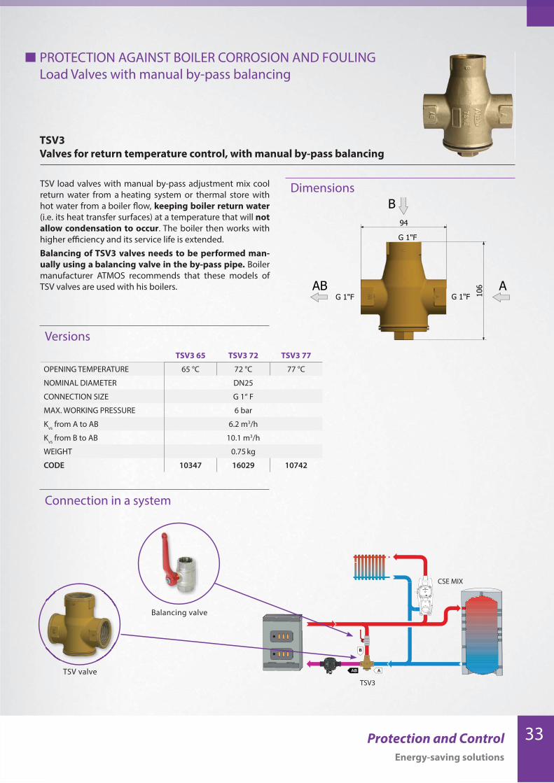
TSV3 65 TSV3 72 TSV3 77
OPENING TEMPERATURE 65 °C 72 °C 77 °C
NOMINAL DIAMETER DN25
CONNECTION SIZE G 1“ F
MAX. WORKING PRESSURE 6 bar
Kvs
from A to AB 6.2 m3/h
Kvs
from B to AB 10.1 m3/h
WEIGHT 0.75 kg
CODE 10347 16029 10742
Connection in a system
Balancing valve
TSV valve
TSV load valves with manual by-pass adjustment mix cool
return water from a heating system or thermal store with
hot water from a boiler flow, keeping boiler return water
(i.e. its heat transfer surfaces) at a temperature that will not
allow condensation to occur. The boiler then works with
higher efficiency and its service life is extended.
Balancing of TSV3 valves needs to be performed man-
ually using a balancing valve in the by-pass pipe. Boiler
manufacturer ATMOS recommends that these models of
TSV valves are used with his boilers. AAB
B94
106
G 1"F
G 1"FG 1"F
PROTECTION AGAINST BOILER CORROSION AND FOULING
Load Valves with manual by-pass balancing
Versions
TSV3
Valves for return temperature control, with manual by-pass balancing
Dimensions

34 Protection and Control
Energy-saving solutions
*50, 60, 70 °C temperatures upon request
Load valve with automatic by-pass balancing, with 1” F
threads on both A and B inlets. The AB outlet is fitted with
a 6/4” F union nut, it involves also a 6/4“ F x 1“ F adapter. The
kit is intended to connect a circulation pump.
Load valve with automatic by-pass balancing, with 1” M
threads on both A and B inlets and a 1” F union nut on the
AB outlet. The union nut permits direct connection to a cir-
culation pump with 1” connection size.
PROTECTION AGAINST BOILER CORROSION AND FOULING
Load Valves with automatic by-pass balancing
TSV3BF
Valves for return temperature control, with automatic by-pass balancing
TSV3BMF
Valves for return temperature control, with automatic by-pass balancing
TSV3BMF 45 TSV3BMF 55 TSV3BMF 65
OPENING TEMPERATURE °C 45 55 65
NOMINAL DIAMETER - G 1“ M G 1“ M G 1“ M
CONNECTION SIZE -- G 1“ F G 1“ F G 1“ F
Kvs
from A to AB m3/h 8.6 8.6 8.6
Kvs
from B to AB m3/h 5.1 5.1 5.1
WEIGHT kg 0.69 0.69 0.69
CODE -- 13980 13981 13982
AAB
B94
107
G 1"F
G 1"FG 6/4"FG 6/4"FG 1"F
A
AB
B10
8
90
G 1"M
G 1"M
G 1"F
ULING
Versions
Versions
Dimensions
Dimensions
TSV3BF 45 TSV3BF 50 TSV3BF 55 TSV3BF 60 TSV3BF 65 TSV3BF 70
OPENING TEMPERATURE °C 45 50 55 60 65 70
NOMINAL DIAMETER - G 1“ F G 1“ F G 1“ F G 1“ F G 1“ F G 1“ F
CONNECTION SIZE -- G 6/4“ F G 6/4“ F G 6/4“ F G 6/4“ F G 6/4“ F G 6/4“ F
Kvs
from A to AB m3/h 6.2 6.2 6.2 6.2 6.2 6.2
Kvs
from B to AB m3/h 4.4 4.4 4.4 4.4 4.4 4.4
WEIGHT kg 0.81 0.81 0.81 0.81 0.81 0.81
CODE -- 13095 15939 13096 15940 13097 15941

35Protection and Control
Energy-saving solutions
Load valve with automatic by-pass balancing and 3/4” F
threads permitting easy connection using copper pipes
with union nuts, e.g. for installation into a boiler.
TSV34BM
Valves for return temperature control, with automatic by-pass balancing
Versions
Dimensions
TSV34BM 45 TSV34BM 55 TSV34BM 65
OPENING TEMPERATURE °C 45 55 65
NOMINAL DIAMETER -- G 3/4“ M G 3/4“ M G 3/4“ M
Kvs
from A to AB m3/h 5.6 5.6 5.6
Kvs
from B to AB m3/h 5.6 5.6 5.6
WEIGHT kg 0.6 0.6 0.6
CODE -- 16928 16409 16929
Only on order!
50, 60, 70 °C temperatures upon request
TSV3BM 45 TSV3BM 55 TSV3BM 65
OPENING TEMPERATURE °C 45 55 65
NOMINAL DIAMETER -- G 1“ M G 1“ M G 1“ M
Kvs
from A to AB m3/h 9.8 9.8 9.8
Kvs
from B to AB m3/h 5.3 5.3 5.3
WEIGHT kg 0.65 0.65 0.65
CODE -- 13977 13978 13979
Load valve with automatic by-pass balancing and 1” M
threads permitting easy connection to copper pipes with
union nuts, e.g. when integrated into a boiler.
PROTECTION AGAINST BOILER CORROSION AND FOULING
Load Valves with automatic by-pass balancing
TSV3BM
Valves for return temperature control, with automatic by-pass balancing
A
AB
B
108
86
G 1"M
G 1"M
G 1"M
Versions
Dimensions
36 Protection and Control
Energy-saving solutions
Connection in a system
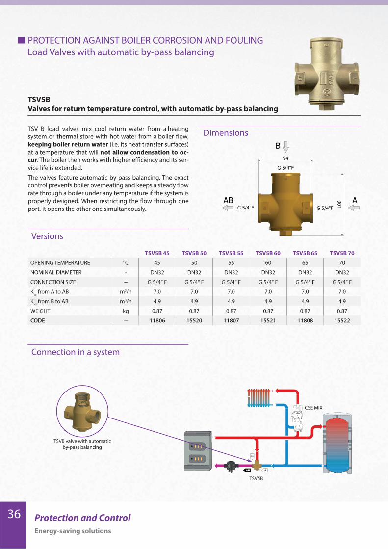
TSV B load valves mix cool return water from a heating
system or thermal store with hot water from a boiler flow,
keeping boiler return water (i.e. its heat transfer surfaces)
at a temperature that will not allow condensation to oc-
cur. The boiler then works with higher efficiency and its ser-
vice life is extended.
The valves feature automatic by-pass balancing. The exact
control prevents boiler overheating and keeps a steady flow
rate through a boiler under any temperature if the system is
properly designed. When restricting the flow through one
port, it opens the other one simultaneously.AB
B
A
94
106
G 5/4"F
G 5/4"FG 5/4"F
PROTECTION AGAINST BOILER CORROSION AND FOULING
Load Valves with automatic by-pass balancing
Versions
TSV5B
Valves for return temperature control, with automatic by-pass balancing
Dimensions
TSV5B 45 TSV5B 50 TSV5B 55 TSV5B 60 TSV5B 65 TSV5B 70
OPENING TEMPERATURE °C 45 50 55 60 65 70
NOMINAL DIAMETER - DN32 DN32 DN32 DN32 DN32 DN32
CONNECTION SIZE -- G 5/4“ F G 5/4“ F G 5/4“ F G 5/4“ F G 5/4“ F G 5/4“ F
Kvs
from A to AB m3/h 7.0 7.0 7.0 7.0 7.0 7.0
Kvs
from B to AB m3/h 4.9 4.9 4.9 4.9 4.9 4.9
WEIGHT kg 0.87 0.87 0.87 0.87 0.87 0.87
CODE -- 11806 15520 11807 15521 11808 15522
AB A
B
B
AAB
CSE MIX
TSV5B
TSVB valve with automatic
by-pass balancing
37Protection and Control
Energy-saving solutions
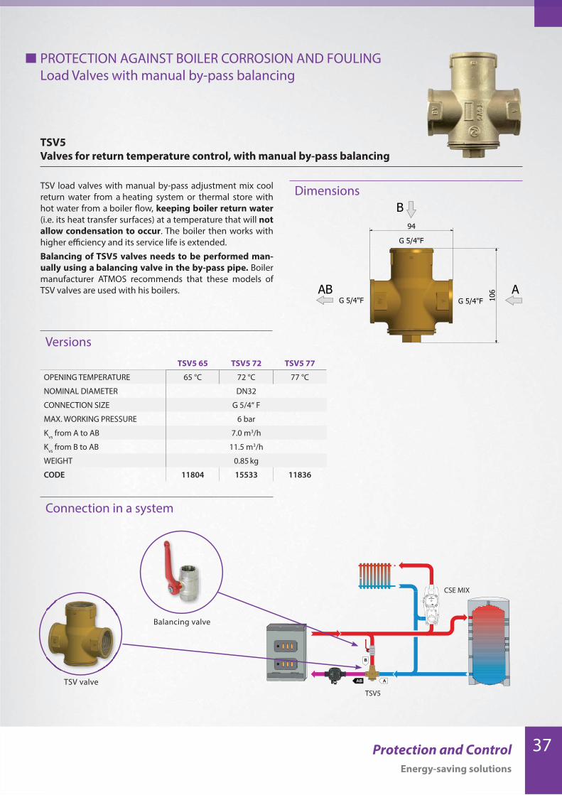
TSV5 65 TSV5 72 TSV5 77
OPENING TEMPERATURE 65 °C 72 °C 77 °C
NOMINAL DIAMETER DN32
CONNECTION SIZE G 5/4“ F
MAX. WORKING PRESSURE 6 bar
Kvs
from A to AB 7.0 m3/h
Kvs
from B to AB 11.5 m3/h
WEIGHT 0.85 kg
CODE 11804 15533 11836
Connection in a system
TSV load valves with manual by-pass adjustment mix cool
return water from a heating system or thermal store with
hot water from a boiler flow, keeping boiler return water
(i.e. its heat transfer surfaces) at a temperature that will not
allow condensation to occur. The boiler then works with
higher efficiency and its service life is extended.
Balancing of TSV5 valves needs to be performed man-
ually using a balancing valve in the by-pass pipe. Boiler
manufacturer ATMOS recommends that these models of
TSV valves are used with his boilers. AB
B
A
94
106
G 5/4"F
G 5/4"FG 5/4"F
PROTECTION AGAINST BOILER CORROSION AND FOULING
Load Valves with manual by-pass balancing
Versions
Dimensions
TSV5
Valves for return temperature control, with manual by-pass balancing
B
AAB
AB A
B
CSE MIX
TSV5
Balancing valve
TSV valve
38 Protection and Control
Energy-saving solutions
Connection in a system
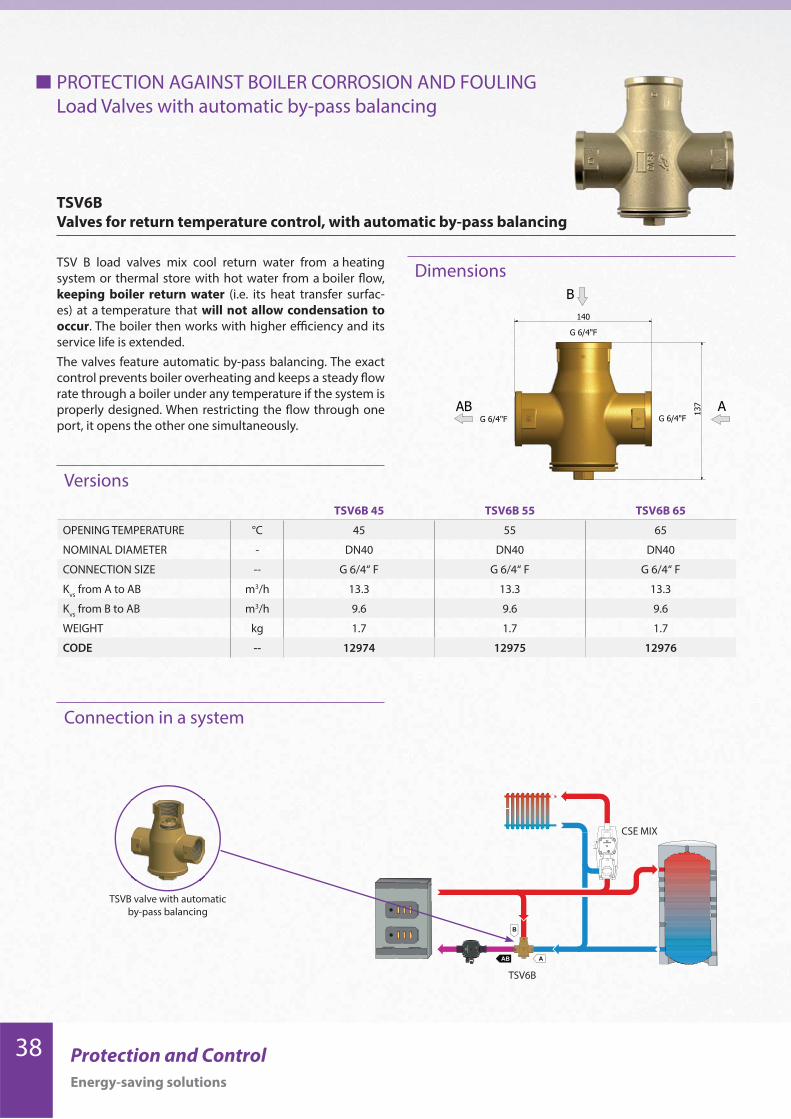
TSV B load valves mix cool return water from a heating
system or thermal store with hot water from a boiler flow,
keeping boiler return water (i.e. its heat transfer surfac-
es) at a temperature that will not allow condensation to
occur. The boiler then works with higher efficiency and its
service life is extended.
The valves feature automatic by-pass balancing. The exact
control prevents boiler overheating and keeps a steady flow
rate through a boiler under any temperature if the system is
properly designed. When restricting the flow through one
port, it opens the other one simultaneously.
TSV6B 45 TSV6B 55 TSV6B 65
OPENING TEMPERATURE °C 45 55 65
NOMINAL DIAMETER - DN40 DN40 DN40
CONNECTION SIZE -- G 6/4“ F G 6/4“ F G 6/4“ F
Kvs
from A to AB m3/h 13.3 13.3 13.3
Kvs
from B to AB m3/h 9.6 9.6 9.6
WEIGHT kg 1.7 1.7 1.7
CODE -- 12974 12975 12976
AB
B
A
140
137
G 6/4"F
G 6/4"FG 6/4"F
PROTECTION AGAINST BOILER CORROSION AND FOULING
Load Valves with automatic by-pass balancing
Versions
TSV6B
Valves for return temperature control, with automatic by-pass balancing
Dimensions
AB A
B
B
AAB
CSE MIX
TSV6B
TSVB valve with automatic
by-pass balancing
39Protection and Control
Energy-saving solutions
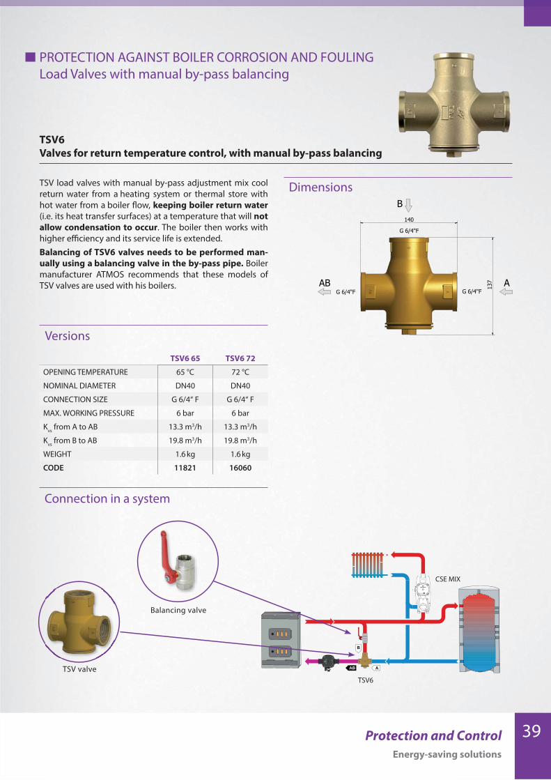
TSV6 65 TSV6 72
OPENING TEMPERATURE 65 °C 72 °C
NOMINAL DIAMETER DN40 DN40
CONNECTION SIZE G 6/4“ F G 6/4“ F
MAX. WORKING PRESSURE 6 bar 6 bar
Kvs
from A to AB 13.3 m3/h 13.3 m3/h
Kvs
from B to AB 19.8 m3/h 19.8 m3/h
WEIGHT 1.6 kg 1.6 kg
CODE 11821 16060
Connection in a system
TSV load valves with manual by-pass adjustment mix cool
return water from a heating system or thermal store with
hot water from a boiler flow, keeping boiler return water
(i.e. its heat transfer surfaces) at a temperature that will not
allow condensation to occur. The boiler then works with
higher efficiency and its service life is extended.
Balancing of TSV6 valves needs to be performed man-
ually using a balancing valve in the by-pass pipe. Boiler
manufacturer ATMOS recommends that these models of
TSV valves are used with his boilers. AB
B
A
140
137
G 6/4"F
G 6/4"FG 6/4"F
PROTECTION AGAINST BOILER CORROSION AND FOULING
Load Valves with manual by-pass balancing
Versions
Dimensions
TSV6
Valves for return temperature control, with manual by-pass balancing
B
AAB
AB A
B
CSE MIX
TSV6
Balancing valve
TSV valve
40 Protection and Control
Energy-saving solutions
Connection in a system
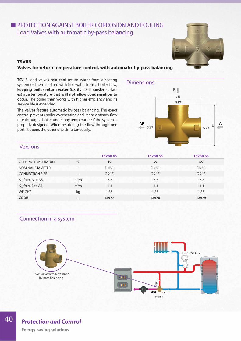
TSV B load valves mix cool return water from a heating
system or thermal store with hot water from a boiler flow,
keeping boiler return water (i.e. its heat transfer surfac-
es) at a temperature that will not allow condensation to
occur. The boiler then works with higher efficiency and its
service life is extended.
The valves feature automatic by-pass balancing. The exact
control prevents boiler overheating and keeps a steady flow
rate through a boiler under any temperature if the system is
properly designed. When restricting the flow through one
port, it opens the other one simultaneously.
TSV8B 45 TSV8B 55 TSV8B 65
OPENING TEMPERATURE °C 45 55 65
NOMINAL DIAMETER - DN50 DN50 DN50
CONNECTION SIZE -- G 2“ F G 2“ F G 2“ F
Kvs
from A to AB m3/h 15.8 15.8 15.8
Kvs
from B to AB m3/h 11.1 11.1 11.1
WEIGHT kg 1.85 1.85 1.85
CODE -- 12977 12978 12979
AB
B
A
152
131
G 2"F
G 2"FG 2"F
PROTECTION AGAINST BOILER CORROSION AND FOULING
Load Valves with automatic by-pass balancing
Versions
TSV8B
Valves for return temperature control, with automatic by-pass balancing
Dimensions
AB A
B
B
AAB
CSE MIX
TSV8B
TSVB valve with automatic
by-pass balancing

41Protection and Control
Energy-saving solutions
TSV8 65 TSV8 72
OPENING TEMPERATURE 65 °C 72 °C
NOMINAL DIAMETER DN50 DN50
CONNECTION SIZE G 2“ F G 2“ F
MAX. WORKING PRESSURE 6 bar 6 bar
Kvs
from A to AB 15.8 m3/h 15.8 m3/h
Kvs
from B to AB 27.4 m3/h 27.4 m3/h
WEIGHT 1.75 kg 1.75 kg
CODE 11819 16061
Connection in a system
TSV load valves with manual by-pass adjustment mix cool
return water from a heating system or thermal store with
hot water from a boiler flow, keeping boiler return water
(i.e. its heat transfer surfaces) at a temperature that will not
allow condensation to occur. The boiler then works with
higher efficiency and its service life is extended.
Balancing of TSV8 valves needs to be performed man-
ually using a balancing valve in the by-pass pipe. Boiler
manufacturer ATMOS recommends that these models of
TSV valves are used with his boilers.AB
B
A
152
131
G 2"F
G 2"FG 2"F
PROTECTION AGAINST BOILER CORROSION AND FOULING
Load Valves with manual by-pass balancing
Versions
Dimensions
TSV8
Valves for return temperature control, with manual by-pass balancing
B
AAB
AB A
B
CSE MIX
TSV8
Balancing valve
TSV valve

42 Protection and Control
Energy-saving solutions
Grundfos circulation pump performance curves
PROTECTION AGAINST BOILER CORROSION AND FOULING
Circulation Pumps
0.0 0.2 0.4 0.6 0.8 1.0 1.2 1.4 1.6 1.8 2.0 2.2 2.4 2.6 2.8 3.0 3.2 3.4 Q [m³/h]0
1
2
3
4
5
6
7[m]H
0.0 0.2 0.4 0.6 0.8 1.0 1.2 1.4 1.6 1.8 2.0 2.2 2.4 2.6 2.8 3.0 3.2 3.4 Q [m³/h]0
10
20
30
40
50
[W]P1
1 2 34
12
3
4
0
1
2
3
4
5
6
7[m]H
0.0 0.2 0.4 0.6 0.8 1.0 1.2 1.4 1.6 1.8 2.0 2.2 2.4 2.6 2.8 3.0 3.2 3.4 Q [m³/h]
0
10
20
30
40
50
[W]P1
0.0 0.2 0.4 0.6 0.8 1.0 1.2 1.4 1.6 1.8 2.0 2.2 2.4 2.6 2.8 3.0 3.2 3.4 Q [m³/h]
Grundfos UPM3 FLEX AS 25-70
Grundfos UPM3 FLEX AS 25-75
43Protection and Control
Energy-saving solutions
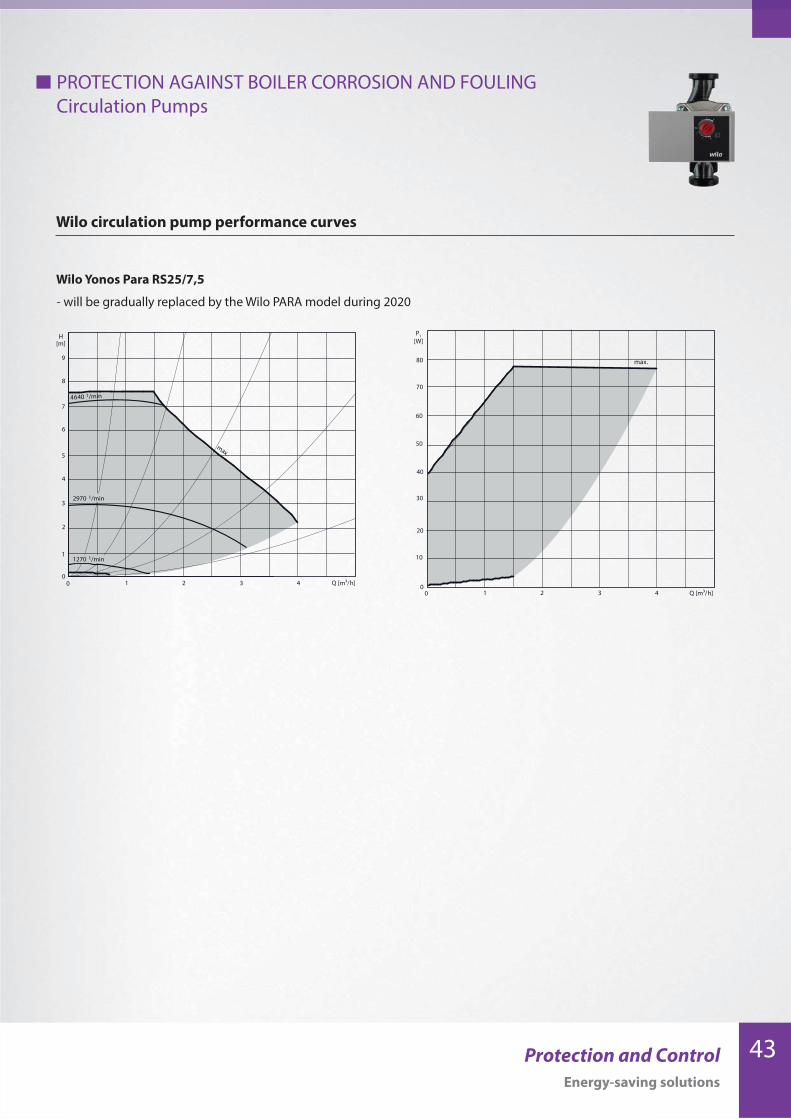
Wilo Yonos Para RS25/7,5
Wilo circulation pump performance curves
PROTECTION AGAINST BOILER CORROSION AND FOULING
Circulation Pumps
0
2
4
6
8
1
3
5
7
9
0 1 2 3 4
1270 1/min
2970 1/min
4640 1/min
max.
H[m]
Q [m³/ h]
max.
0 1 2 3 40
20
40
50
60
70
80
30
10
P1[W]
Q [m³/ h]
- will be gradually replaced by the Wilo PARA model during 2020
44 Protection and Control
Energy-saving solutions
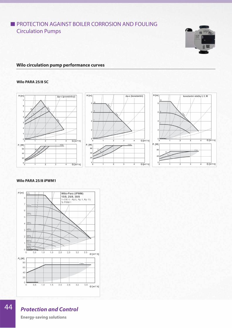
Wilo circulation pump performance curves
PROTECTION AGAINST BOILER CORROSION AND FOULING
Circulation Pumps
Wilo PARA 25/8 SC
Wilo PARA 25/8 iPWM1

45Protection and Control
Energy-saving solutions
46 Protection and Control
Energy-saving solutions
Dimensions
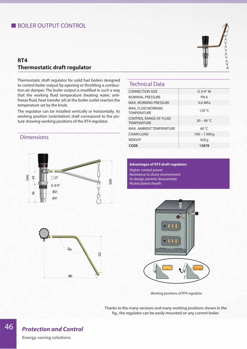
BOILER OUTPUT CONTROL
Thermostatic draft regulator for solid fuel boilers designed
to control boiler output by opening or throttling a combus-
tion air damper. The boiler output is modified in such a way
that the working fluid temperature (heating water, anti-
freeze fluid, heat transfer oil) at the boiler outlet reaches the
temperature set by the knob.
The regulator can be installed vertically or horizontally. Its
working position (orientation) shall correspond to the pic-
ture showing working positions of the RT4 regulator.
Working positions of RT4 regulator.
RT4
Thermostatic draft regulator
Technical DataCONNECTION SIZE G 3/4“ M
NOMINAL PRESSURE PN 6
MAX. WORKING PRESSURE 0.6 MPa
MAX. FLUID WORKING
TEMPERATURE120 °C
CONTROL RANGE OF FLUID
TEMPERATURE30 – 90 °C
MAX. AMBIENT TEMPERATURE 60 °C
CHAIN LOAD 100 – 1 000 g
WEIGHT 420 g
CODE 13878
Advantages of RT4 draft regulator:
Higher control power
Resistance to dusty environment
Its design permits disassembly
Nickel plated sheath
(154)
5643
G 3/4"
Ø21
Ø17
1250
27
180
122
120°
Thanks to the many versions and many working positions shown in the
fig., the regulator can be easily mounted on any current boiler.

47Protection and Control
Energy-saving solutions
Modified variants
RT4 T differs in the sheath shape, RT4 L and S were developed from the basic RT4 model but they differ in the lever shape.
RT4T - for boilers with a thicker mantle - Code: 14138
RT4L - with a longer lever - Code: 14743
RT4S - with a right-angled lever, 313 mm distance - Code: 14716
Utility model granted
(154)
5643
G 3/4"
Ø21
Ø17
1250
27 90°
314
122
(154)
5643
G 3/4"
Ø21
Ø17
1250
27
215
122
120°
1250
27
G 3/4"
(154)
6237 Ø21,2
Ø17,2180
122
120°

48 Protection and Control
Energy-saving solutions
RT3E - TP44
RT3E - TP546
room
thermostat
12V
power
supply
Electric controlled draft regulator works like RT4, more-
over it permits reducing boiler flow temperature on an
electric signal. Both flow temperature and heat output
can be controlled by a room thermostat or another elec-
tronic controller.
It is fitted with a 3m silicone cable.
When energized with 12V tension, the regulator will re-
duce the boiler flow temperature.
When not energized, it keeps the temperature at the val-
ue set by the knob.
The regulator can be also controlled continuously by
0-12V.
It is supplied either separately or as a kit containing a 12V
power supply and either a TP546 mechanical thermostat
or a TP44 electronic programmable thermostat.
RT3E Regulator is
protected by a patent.
Version RT3E RT3E+TP44 RT3E+TP546
Code 7191 9138 9139
1250
43
179
74
G 3/4"
Ø24
17
180
122
120°
BOILER OUTPUT CONTROL
RT3E
Thermostatic draft regulator, electric operated
Kits with a thermostat
Dimensions

49Protection and Control
Energy-saving solutions
Recommended