D
PSS BG 4 AP/CPClosed-circuit breathing apparatus
Instructions for Use
128
215
84
.tif
Contents
2
Contents
For Your Safety . . . . . . . . . . . . . . . . . . . . . . . . . . . . . . . . . . .3
Intended Use . . . . . . . . . . . . . . . . . . . . . . . . . . . . . . . . . . . . .4
Designation . . . . . . . . . . . . . . . . . . . . . . . . . . . . . . . . . . . . . .4
Description . . . . . . . . . . . . . . . . . . . . . . . . . . . . . . . . . . . . . .6
Prerequisites for Use . . . . . . . . . . . . . . . . . . . . . . . . . . . . . .7
Cautions and Limitations . . . . . . . . . . . . . . . . . . . . . . . . . . .7
Preparation for Operation . . . . . . . . . . . . . . . . . . . . . . . . 10
Preparation for Use . . . . . . . . . . . . . . . . . . . . . . . . . . . . . 17
Practical Use . . . . . . . . . . . . . . . . . . . . . . . . . . . . . . . . . . . 27
After Use . . . . . . . . . . . . . . . . . . . . . . . . . . . . . . . . . . . . . . 32
Testing . . . . . . . . . . . . . . . . . . . . . . . . . . . . . . . . . . . . . . . . 48
Storage . . . . . . . . . . . . . . . . . . . . . . . . . . . . . . . . . . . . . . . 59
Disposal of Consumables . . . . . . . . . . . . . . . . . . . . . . . . 59
Maintenance Intervals . . . . . . . . . . . . . . . . . . . . . . . . . . . 60
Technical Data . . . . . . . . . . . . . . . . . . . . . . . . . . . . . . . . . . 61
Order List . . . . . . . . . . . . . . . . . . . . . . . . . . . . . . . . . . . . . . 63
3
For Your Safety
For Your Safety
These Instructions for Use (this Manual) for the PSS BG 4 AP/CP closed-circuit breathing apparatus (“PSS BG 4” or “the device”) are designed to be a guideline to the proper use of the PSS BG 4. This Manual is not a substitute for thorough, appropriate training and certification in the use of the PSS BG 4.
This Manual could not possibly contain all the information needed to safely use the PSS BG 4. However, it will help you understand the performance characteristics and maintenance requirements of the PSS BG 4, which, when combined with appropriate hands-on training and certification, will enable you to properly use the device.
This Manual also provides you with necessary manufacturer’s guidelines for maintenance intervals and service of the device (see, for example, “Maintenance Intervals” on page 60). These guidelines must be strictly followed to avoid your being very badly injured or killed. For this reason (and many others), it is extremely important that you read and understand every aspect of this Manual, in addition to receiving proper training and certification, before attempting to use the device. Should you not thoroughly understand any aspect of the Manual, call Dräger at 800-922-5518. A Dräger representative will be happy to address your questions, free of charge.
The PSS BG 4 may only be used for the purposes specified in these Instructions for Use (see “Intended Use” on page 4).
The PSS BG 4 must never be used underwater.
Safety Symbols used in this Manual
While reading this Manual, you will come across a number of warnings concerning some of the risks and dangers you may face while using the device. These warnings contain “signal” words that will alert you to the degree of hazard you may encounter. These words, and the hazard they describe, are as follows:
DANGER!
Indicates an imminently hazardous situation which, if not avoided, will result in death or serious injury.
WARNING!
Indicates a potentially hazardous situation which, if not avoided, could result in death or serious injury.
CAUTION!
Indicates a potentially hazardous situation which, if not avoided, could result in physical injury to you, or damage to the product.
It may also be used to alert against unsafe practices.
Furthermore, there are more general notes which are indicated as follows:
Maintenance
Regular service, maintenance, and pre-use checkouts of your PSS BG 4 is of the utmost importance to ensure safe use of the device. Thus it is absolutely mandatory that you strictly follow the “Maintenance Intervals” on page 60.
Repair of the PSS BG 4 may only be carried out by trained and qualified service personnel.
We recommend you enter into a service contract with Dräger Safety; that all repairs on your PSS BG 4 be conducted by Dräger Safety; and that only authentic Dräger parts be used for maintenance and repairs.
Warranty and Limitation of Liability
Dräger shall not be liable for any damages caused by the incorrect use, servicing, or repair of the product. Dräger shall not be liable for any damages caused by a failure to properly follow these Instructions for Use.
The warranty and liability conditions set forth in the Dräger Sales and Delivery Conditions comprise the exclusive remedies available to the user. Nothing in these Instructions for Use shall be deemed to extend or expand the remedies set forth in the Dräger Sales and Delivery Conditions.
Dräger Safety AG & Co. KGaA
NOTE
indicates additional information on how to use the device.
WARNING!
The PSS BG 4 must be regularly inspected and serviced by qualified service personnel, and the “Maintenance Intervals” on page 60 must be strictly followed.
Failure to follow this warning could lead to death or serious injury.
4
Intended Use
Intended Use
The PSS BG 4 closed-circuit breathing apparatus for use by the fire services and for appropriate missions in underground and open-cast mines, as well as in industry. The PSS BG 4 supplies its wearer with breathing air, thus making it unnecessary for the wearer to breath polluted ambient air lacking in oxygen.
Designation
USA use the PSS BG 4 AP.The period of use1)
with oxygen cylinder steel R 27 082 is 4 hours,with oxygen cylinder CFK B 30 229 is 4 hours.
Canada use the PSS BG 4 CP.The period of use1)with oxygen cylinder CFK B 30 230 is 4 hours,with oxygen cylinder steel B 03 390 is 4 hours.
WARNING!
The PSS BG 4 was designed, checked and approved of according to the NIOSH guidelines 42 CFR, part 84, subpart H. For this reason, it must never be used for diving.
Use of the PSS BG 4 under water could lead to death or serious injury.
1) under moderately severe conditions.
5
Designation
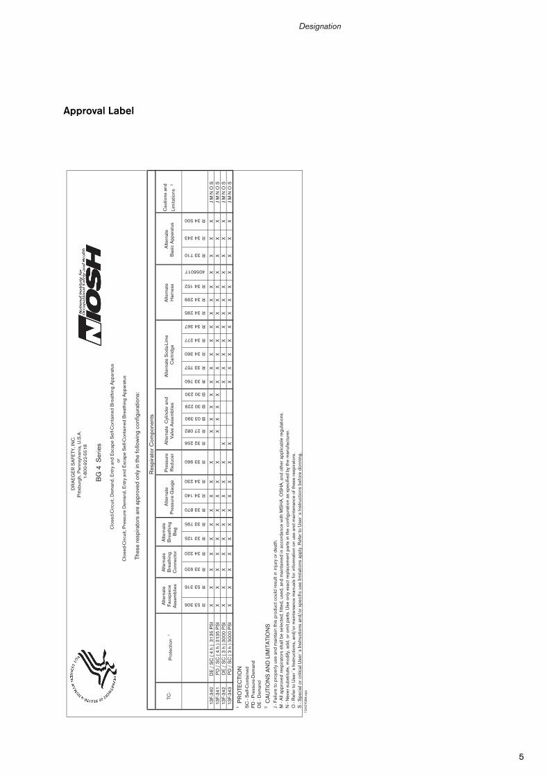
Approval Label
DR
AE
GE
R S
AFE
TY, I
NC
.P
ittsb
urgh
, Pen
nsyl
vani
a, U
.S.A
.1
-80
0-9
22
-55
18
BG
4 S
erie
s
Clo
sed-
Circ
uit,
Dem
and,
Ent
ry a
nd E
scap
e S
elf-C
onta
ined
Bre
athi
ng A
ppar
atus
orC
lose
d-C
ircui
t, P
ress
ure
Dem
and,
Ent
ry a
nd E
scap
e S
elf-C
onta
ined
Bre
athi
ng A
ppar
atus
Thes
e re
spira
tors
are
app
rove
d on
ly in
the
follo
win
g co
nfig
urat
ions
:
Res
pira
tor
Com
pone
nts
TC-
Pro
tect
ion
1
Alte
rnat
e Fa
cepi
ece
Ass
embl
ies
Alte
rnat
e B
reat
hing
C
onne
ctor
Alte
rnat
e B
reat
hing
B
ag
Alte
rnat
e P
ress
ure
Gau
geP
ress
ure
Red
ucer
Alte
rnat
e C
ylin
der
and
Val
ve A
ssem
blie
sA
ltern
ate
Har
ness
Alte
rnat
e B
asic
App
arat
usC
autio
ns a
nd
Lim
itatio
ns
2R 53 306
R 53 316
R 33 920
R 34 320
R 33 125
R 33 795
R 33 870
R 34 140
R 34 230
R 33 960
R 32 256
R 27 082
B 03 390
B 30 229
B 30 230
R 33 760
R 33 757
R 34 360
R 34 277
R 34 367
R 34 295
R 34 299
R 34 152
4056017
R 33 710
R 34 343
R 34 500
13
F-3
40
DE
/ S
C (
4 h
) 3
13
5 P
SI
XX
XX
XX
XX
XX
XX
XX
XX
XX
XX
XX
XX
XX
J M
N O
S1
3F-
34
1P
D /
SC
( 4
h )
31
35
PS
IX
XX
XX
XX
XX
XX
XX
XX
XX
XX
XX
XX
XX
XJ
M N
O S
13
F-3
42
DE
/ S
C (
3 h
) 3
00
0 P
SI
XX
XX
XX
XX
XX
XX
XX
XX
XX
XX
XX
XJ
M N
O S
13
F-3
43
PD
/ S
C (
3 h
) 3
00
0 P
SI
XX
XX
XX
XX
XX
XX
XX
XX
XX
XX
XX
XJ
M N
O S
1 PR
OTE
CTI
ON
SC
- S
elf-C
onta
ined
PD
- P
ress
ure-
Dem
and
DE
- D
eman
d2 C
AU
TIO
NS
AN
D L
IMIT
ATI
ON
SJ
- Fai
lure
to p
rope
rly u
se a
nd m
aint
ain
this
pro
duct
cou
ld r
esul
t in
inju
ry o
r de
ath.
M -
All
appr
oved
res
pira
tors
sha
ll be
sel
ecte
d, fi
tted,
use
d, a
nd m
aint
aine
d in
acc
orda
nce
with
MS
HA
, OS
HA
, and
oth
er a
pplic
able
reg
ulat
ions
.N
- N
ever
sub
stitu
te, m
odify
, add
, or
omit
part
s. U
se o
nly
exac
t rep
lace
men
t par
ts in
the
conf
igur
atio
n as
spe
cifie
d by
the
man
ufac
ture
r.O
- R
efer
to U
ser´
s In
stru
ctio
ns, a
nd/o
r m
aint
enan
ce m
anua
ls fo
r in
form
atio
n on
use
and
mai
nten
ance
of t
hese
res
pira
tors
.S
- S
peci
al o
r cr
itica
l Use
r´s
Inst
ruct
ions
and
/or
spec
ific
use
limita
tions
app
ly. R
efer
to U
ser´
s In
stru
ctio
ns b
efor
e do
nnin
g.
Alte
rnat
e S
oda-
Lim
e C
artr
idge
12
42
15
84
.eps
6
Description
Description
The breathing air is circulated in a closed breathing cycle. The carbon dioxide contained in the exhaled air is absorbed in a regeneration cartridge (CO2 absorber).
The breathing air is enriched with oxygen from the oxygen cylinder
— via the constant metering valve, in the case of low breathing rates, and
— via the minimum valve or a manually operated bypass valve in the case of higher breathing rates.
Before the regenerated breathing air is inhaled again, it flows through the air cooler. When it is filled with ice the temperature of the inhaled air is lowered, thus reducing the physical strain on the user.
The use of ice in the cooling system is only required at ambient temperatures above 32 oF (0 oC). At temperatures below 32 oF (0 oC), ice must never be used.
A positive pressure in the breathing circuit prevents ambient air from entering the system.
Only use the corresponding full-face masksPanorama Nova – EPDM – PC – RP orPanorama Nova – SI – PC – RPThey are connected to the PSS BG 4 via a quick and easy plug-in coupling.
The electronic monitoring system comprises sensor unit, switch-box and Sentinel. It continuously measures the pressure in the oxygen cylinder, indicates this pressure on the Sentinel, tests and monitors the correct functioning of the PSS BG 4 and generates a warning when the residual pressure is reached as well as in the event of malfunctions.
Sentinel provides continuous monitoring of the PSS BG 4 equipment and movement of the wearer.
Sentinel incorporates the following features:
— Monitoring of available oxygen pressure of the PSS BG 4 equipment;
— Remaining period of use in minutes until approx.700 psi/55 bar residual pressure warning is generated;
— Movement Sensor and Automatic Distress Signal Unit (ADSU). This feature is active only when the ‘Tally’ is removed;
— Yellow panic button activated manual Distress Signal-Unit (DSU);
— Battery capacity;
— A ‘Back Light’ feature – illumination of the display;
— Residual pressure warning at 700 psi/55 bar;
— Ambient temperature;
— Intrinsic safety approved;
— Low pressure warning which warns during use that either the cylinder valve is closed or the oxygen cylinder is empty.
Available for Sentinel are ‘snap on’ IR-Link and Windows based Software Packages for the programming of additional monitoring options and datalogging with downloading of datalogged parameters.
Details of variants, approved accessories and IR-Link with Windows based Software. Package Options are available from Dräger Safety on request.
The PSS BG 4 equipment with the permitted breathing apparatus connections complies with
— the European standard DIN EN 145 and
— the European PPE Directive 89/686/EEC.
The Sentinel electronic monitoring system satisfies the explosion-protection (intrinsic safety) tests in accordance with EN 50 020 regulation:
— EEx ia IIC T4
— EEx ia I
The Sentinel meets the explosion-proofing standards to EEx ia IIC T4 and EEx ia I and is approved for the use in gaseous mines by MSHA.
7
Prerequisites for Use
Prerequisites for Use
— The possible need for protective clothing and head protection must be noted when verifying the conditions for use.
— National regulations must be strictly followed, such as (for Germany):BGR 190 "Regulations for the use of breathing apparatus"BGI 504-26: Selection criteria for special industrial medical precautions in accordance with recommendation G 26 "Breathing apparatus" published by the employers' liability insurance association.
Cautions and Limitations
(Refer to the approved User Instruction manual for the complete list of sub-assembly component parts that make up the approved assembly).
J - Failure to properly use and maintain this product could result in injury or death.
M- All approved respirators shall be selected, fitted, used, and maintained in accordance with MSHA, OSHA, and other applicable regulations.
N - Never substitute, modify, add, or omit parts. Use only exact replacement parts in the configuration as specified by the manufacturer.
O - Refer to User´s Instructions, and/or maintenance manuals for information on use and maintenance of these respirators.
S - Special or critical user´s instructions and/or specific use limitations apply. Refer to User´s Instructions before donning.
S – Special or Critical User´s Instructions
— Approved for use at temperatures above 23 oF (–5 oC).
— The use of ice in the cooling system is only required at ambient temperatures above 32 oF (0 oC).At temperatures below 32 oF (0 oC) ice must never be used.
— The cylinder is to be charged with compressed oxygen meeting U.S.P. specifications.
— Anti-fog solution R 52 560 or R 52 550 must be applied before each use.
— The CO2 absorber must never be used after its indicated expiration date. See Instructions for Use of refill cartridge 90 21 360.
— Never re-use factory-packed cartridge R 34 360.
— After each use of the PSS BG 4, a fully charged cylinder and a recharged CO2 absorber must be installed.
— Thorough cleaning and disinfecting of facepiece, breathing tube and breathing bag must be done in accordance with the manufacturer´s instructions.
— When used as a Pressure Demand Apparatus, the following Warnings and Limitations apply:
— Do not use this apparatus where there is direct exposure of open flames or in high radiant heat.
— Keep exposed hair to a minimum when using the apparatus near open flames or in high radiant heat.
— A good facepiece seal is crucial since facepiece leakage will seriously reduce service time.
— Use of pure oxygen or oxygen enriched air increases flammability and lowers the ignition temperature of most materials.
8
What is What
What is What
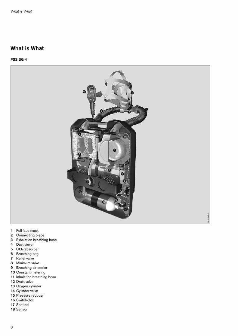
PSS BG 4
1 Full-face mask2 Connecting piece3 Exhalation breathing hose4 Dust sieve5 CO2 absorber6 Breathing bag7 Relief valve8 Minimum valve9 Breathing air cooler10 Constant metering11 Inhalation breathing hose12 Drain valve13 Oxygen cylinder14 Cylinder valve15 Pressure reducer16 Switch-Box17 Sentinel18 Sensor
001
215
48
.tif
9
What is What
What is what
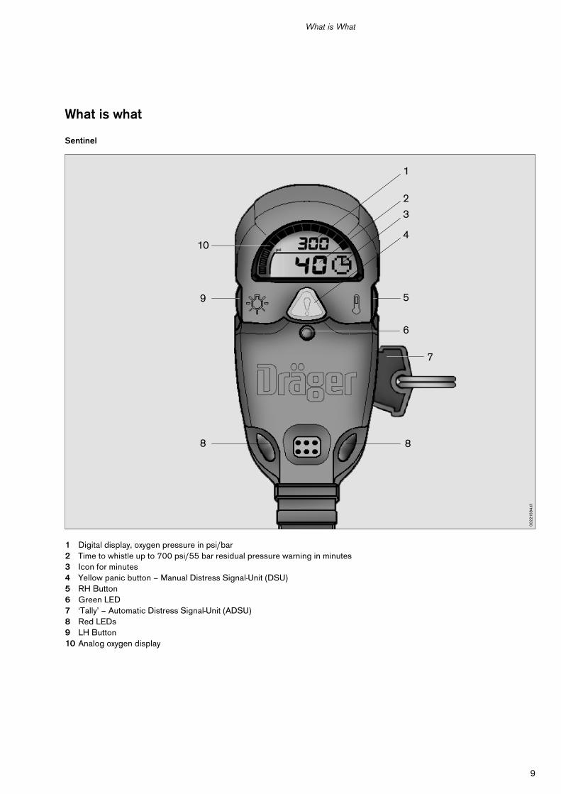
Sentinel
1 Digital display, oxygen pressure in psi/bar2 Time to whistle up to 700 psi/55 bar residual pressure warning in minutes3 Icon for minutes4 Yellow panic button – Manual Distress Signal-Unit (DSU)5 RH Button6 Green LED7 ‘Tally’ – Automatic Distress Signal-Unit (ADSU)8 Red LEDs9 LH Button10 Analog oxygen display
1
2
3
4
5
6
88
9
10
7
00
221
58
4.ti
f
10
Preparation for Operation
Preparation for Operation
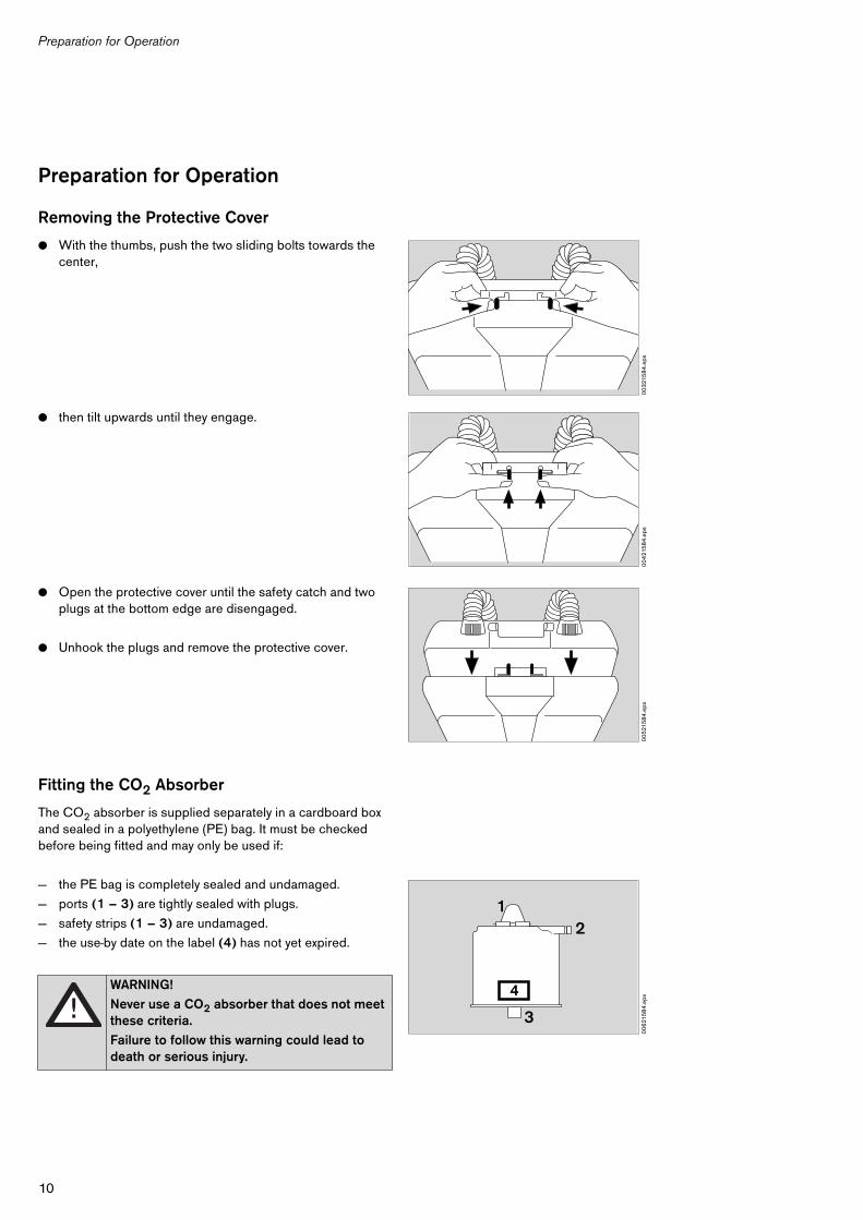
Removing the Protective Cover
● With the thumbs, push the two sliding bolts towards the center,
● then tilt upwards until they engage.
● Open the protective cover until the safety catch and two plugs at the bottom edge are disengaged.
● Unhook the plugs and remove the protective cover.
Fitting the CO2 Absorber
The CO2 absorber is supplied separately in a cardboard box and sealed in a polyethylene (PE) bag. It must be checked before being fitted and may only be used if:
— the PE bag is completely sealed and undamaged.
— ports (1 – 3) are tightly sealed with plugs.
— safety strips (1 – 3) are undamaged.
— the use-by date on the label (4) has not yet expired.
WARNING!
Never use a CO2 absorber that does not meet these criteria.
Failure to follow this warning could lead to death or serious injury.
00
321
58
4.e
ps0
04
215
84
.eps
00
521
58
4.e
ps0
06
215
84
.eps
12
3
4
11
Preparation for Operation
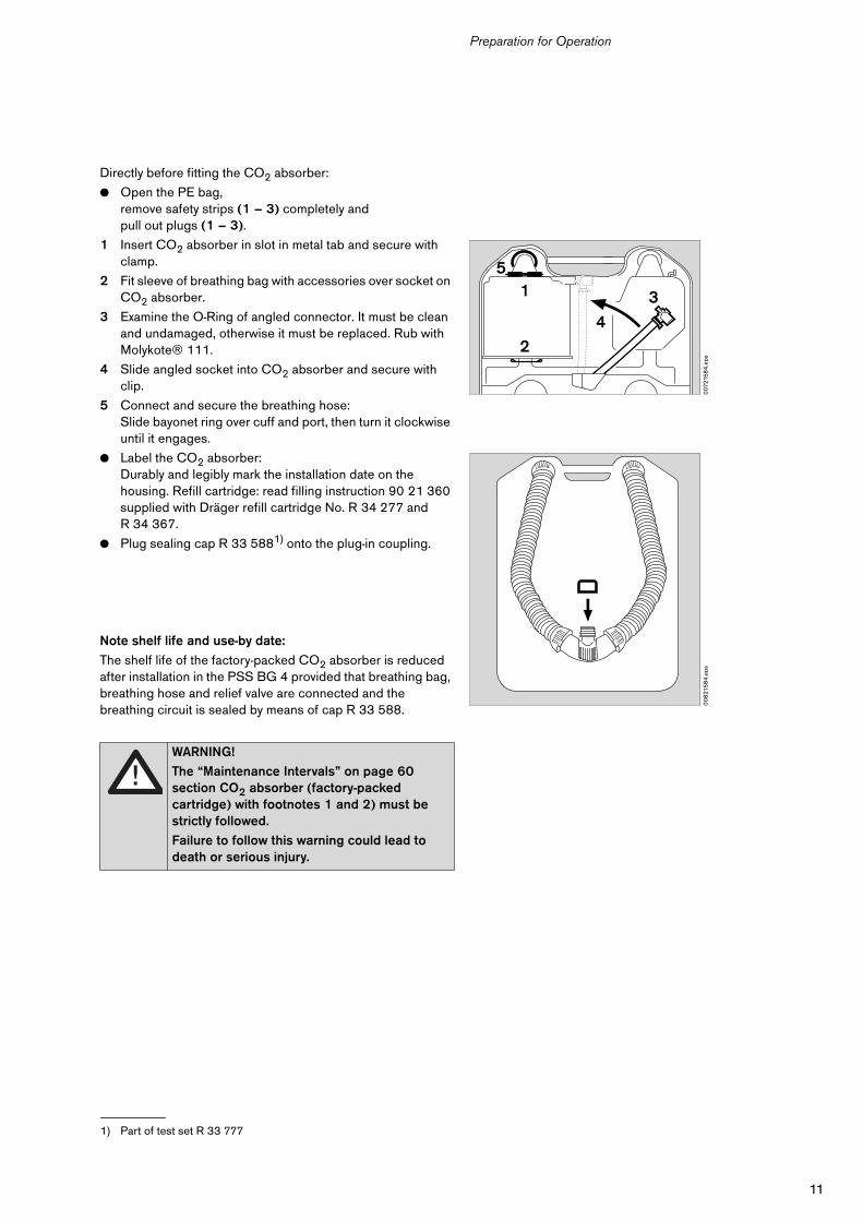
Directly before fitting the CO2 absorber:
● Open the PE bag,remove safety strips (1 – 3) completely andpull out plugs (1 – 3).
1 Insert CO2 absorber in slot in metal tab and secure with clamp.
2 Fit sleeve of breathing bag with accessories over socket on CO2 absorber.
3 Examine the O-Ring of angled connector. It must be clean and undamaged, otherwise it must be replaced. Rub with Molykote® 111.
4 Slide angled socket into CO2 absorber and secure with clip.
5 Connect and secure the breathing hose:Slide bayonet ring over cuff and port, then turn it clockwise until it engages.
● Label the CO2 absorber:Durably and legibly mark the installation date on the housing. Refill cartridge: read filling instruction 90 21 360 supplied with Dräger refill cartridge No. R 34 277 and R 34 367.
● Plug sealing cap R 33 5881) onto the plug-in coupling.
Note shelf life and use-by date:
The shelf life of the factory-packed CO2 absorber is reduced after installation in the PSS BG 4 provided that breathing bag, breathing hose and relief valve are connected and the breathing circuit is sealed by means of cap R 33 588.
1) Part of test set R 33 777
WARNING!
The “Maintenance Intervals” on page 60 section CO2 absorber (factory-packed cartridge) with footnotes 1 and 2) must be strictly followed.
Failure to follow this warning could lead to death or serious injury.
007
215
84
.eps
5
2
4
1 3
00
821
58
4.e
ps
12
Preparation for Operation
Battery
The PSS BG 4 equipment is supplied with a battery.Only the following approved battery types may be used:
— Rayovac AL9V, A1604, 6LF22
— Eveready 522
— Panasonic 6AM6
Only battery type – Rayovac AL9V – is supplied by Dräger Safety (see “Order List” on page 63).
The battery life depends on the following factors:
— Sentinel operating time
— Frequency of alarms
— Ambient temperature
— Frequency of use of the back lighting
A small amount of battery power is consumed when Sentinel is switched off.
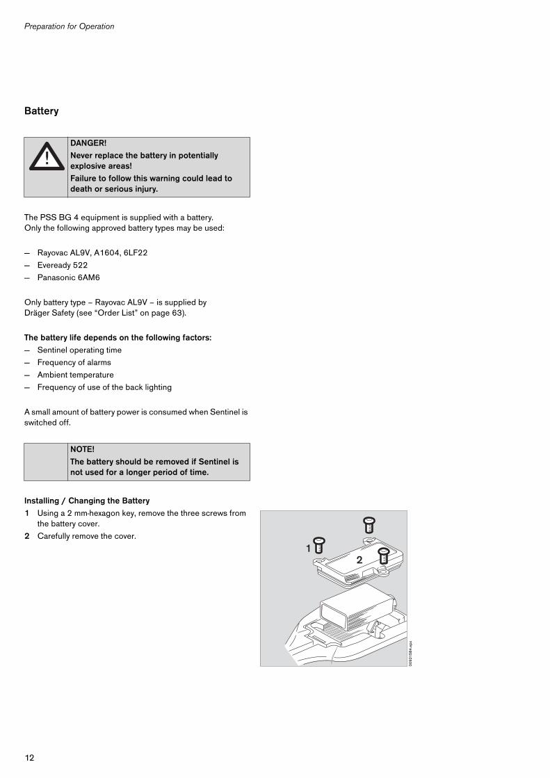
Installing / Changing the Battery
1 Using a 2 mm-hexagon key, remove the three screws from the battery cover.
2 Carefully remove the cover.
DANGER!
Never replace the battery in potentially explosive areas!
Failure to follow this warning could lead to death or serious injury.
NOTE!
The battery should be removed if Sentinel is not used for a longer period of time.
00
921
58
4.e
ps
12
13
Preparation for Operation
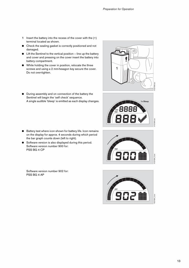
1 Insert the battery into the recess of the cover with the (+) terminal located as shown.
● Check the sealing gasket is correctly positioned and not damaged.
● Lift the Sentinel to the vertical position – line up the battery and cover and pressing on the cover insert the battery into battery compartment.
● While holding the cover in position, relocate the three screws and using a 2 mm-hexagon key secure the cover.Do not over-tighten.
● During assembly and on connection of the battery the Sentinel will begin the ‘self check’ sequence. A single audible ‘bleep’ is emitted as each display changes.
● Battery test where icon shown for battery life. Icon remains on the display for approx. 4 seconds during which period the bar graph counts down (left to right).
● Software version is also displayed during this period.Software version number 900 for:PSS BG 4 CP
Software version number 902 for:PSS BG 4 AP
010
215
84
.eps
1
0112
158
4.e
ps
1x Bleep
psibar
012
215
84
_2.e
ps
bar
116
215
84
_2.e
ps
psi
14
Preparation for Operation
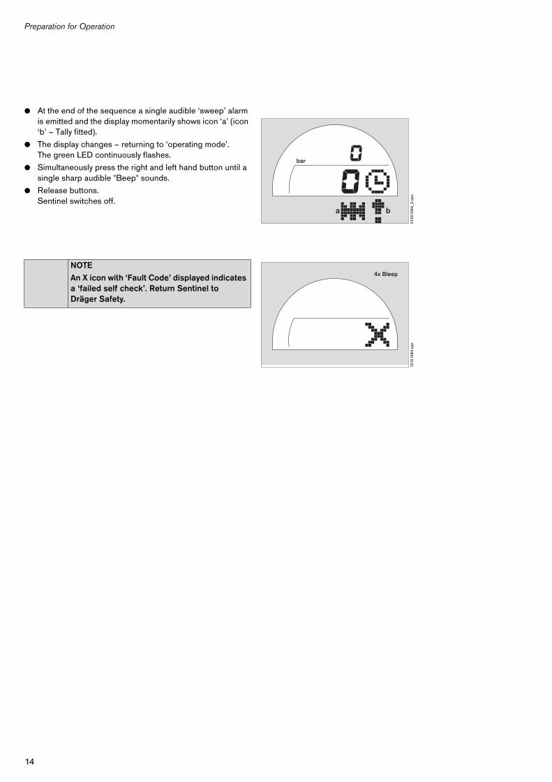
● At the end of the sequence a single audible ‘sweep’ alarm is emitted and the display momentarily shows icon ‘a’ (icon ‘b’ – Tally fitted).
● The display changes – returning to ‘operating mode’.The green LED continuously flashes.
● Simultaneously press the right and left hand button until a single sharp audible "Beep" sounds.
● Release buttons.Sentinel switches off.
NOTE
An X icon with ‘Fault Code’ displayed indicates a ‘failed self check’. Return Sentinel to Dräger Safety.
013
215
84
_2.e
ps
bar
a b
1212
158
4.e
ps
4x Bleep
15
Preparation for Operation
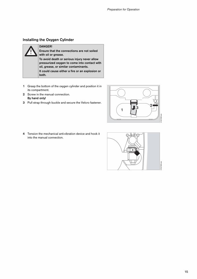
Installing the Oxygen Cylinder
1 Grasp the bottom of the oxygen cylinder and position it in its compartment.
2 Screw in the manual connection.By hand only!
3 Pull strap through buckle and secure the Velcro fastener.
4 Tension the mechanical anti-vibration device and hook it into the manual connection.
DANGER!
Ensure that the connections are not soiled with oil or grease.
To avoid death or serious injury never allow pressurized oxygen to come into contact with oil, grease, or similar contaminants.
It could cause either a fire or an explosion or both.
014
215
84
.eps
13
2
015
215
84
.eps
4
16
Preparation for Operation
Testing the PSS BG 4
see “Testing” on page 48 onwards.
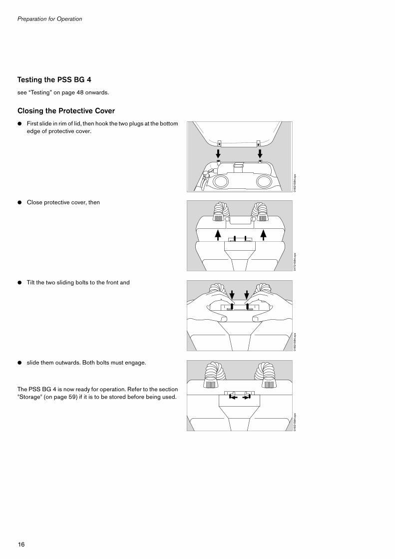
Closing the Protective Cover
● First slide in rim of lid, then hook the two plugs at the bottom edge of protective cover.
● Close protective cover, then
● Tilt the two sliding bolts to the front and
● slide them outwards. Both bolts must engage.
The PSS BG 4 is now ready for operation. Refer to the section "Storage" (on page 59) if it is to be stored before being used.
016
215
84
.eps
0172
158
4.e
ps01
821
58
4.e
ps01
921
58
4.e
ps
17
Preparation for Use
Preparation for Use
When Using the Ice Pack
The air cooler can be filled with ice to reduce the temperature of the inhaled air and thereby minimize discomfort for the wearer.
Operation without ice pack is permitted only when ambient air temperatures are below 32 oF (0 oC), see “S – Special or Critical User´s Instructions” on page 7.
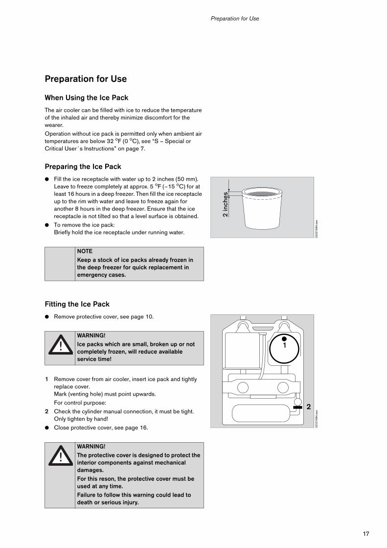
Preparing the Ice Pack
● Fill the ice receptacle with water up to 2 inches (50 mm). Leave to freeze completely at approx. 5 oF (–15 oC) for at least 16 hours in a deep freezer. Then fill the ice receptacle up to the rim with water and leave to freeze again for another 8 hours in the deep freezer. Ensure that the ice receptacle is not tilted so that a level surface is obtained.
● To remove the ice pack:Briefly hold the ice receptacle under running water.
Fitting the Ice Pack
● Remove protective cover, see page 10.
1 Remove cover from air cooler, insert ice pack and tightly replace cover.Mark (venting hole) must point upwards.
For control purpose:
2 Check the cylinder manual connection, it must be tight. Only tighten by hand!
● Close protective cover, see page 16.
NOTE
Keep a stock of ice packs already frozen in the deep freezer for quick replacement in emergency cases.
WARNING!
Ice packs which are small, broken up or not completely frozen, will reduce available service time!
WARNING!
The protective cover is designed to protect the interior components against mechanical damages.
For this reson, the protective cover must be used at any time.
Failure to follow this warning could lead to death or serious injury.
02
021
58
4.e
ps
2 in
ches
021
215
84
.eps
2
1
18
Preparation for Use
Checking Correct Functioning
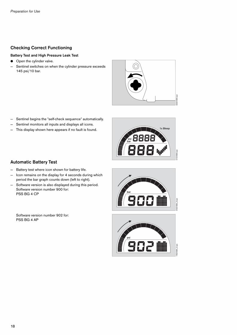
Battery Test and High Pressure Leak Test
● Open the cylinder valve.
— Sentinel switches on when the cylinder pressure exceeds 145 psi/10 bar.
— Sentinel begins the "self-check sequence" automatically.
— Sentinel monitors all inputs and displays all icons.
— This display shown here appears if no fault is found.
Automatic Battery Test
— Battery test where icon shown for battery life.
— Icon remains on the display for 4 seconds during which period the bar graph counts down (left to right).
— Software version is also displayed during this period.Software version number 900 for:PSS BG 4 CP
Software version number 902 for:PSS BG 4 AP
02
221
58
4.e
ps01
1215
84
.eps
1x Bleep
psibar
012
215
84
_2.e
ps
bar
116
215
84
_2.e
ps
psi
19
Preparation for Use
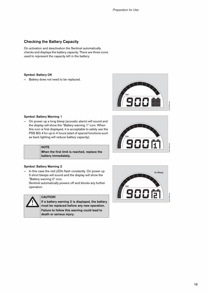
Checking the Battery Capacity
On activation and deactivation the Sentinel automatically checks and displays the battery capacity. There are three icons used to represent the capacity left in the battery:
Symbol: Battery OK
— Battery does not need to be replaced.
Symbol: Battery Warning 1
— On power up a long bleep (acoustic alarm) will sound and the display will show the "Battery warning 1" icon. When this icon is first displayed, it is acceptable to safely use the PSS BG 4 for up to 4 hours (start of special functions such as back lighting will reduce battery capacity).
Symbol: Battery Warning 2
— In this case the red LEDs flash constantly. On power up 5 short bleeps will sound and the display will show the "Battery warning 2" icon.Sentinel automatically powers off and blocks any further operation.
NOTE
When the first limit is reached, replace the battery immediately.
CAUTION!
If a battery warning 2 is displayed, the battery must be replaced before any new operation.
Failure to follow this warning could lead to death or serious injury.
012
215
84
.eps
bar
02
321
58
4.e
ps
bar
024
215
84
.eps
bar
5x Bleep
20
Preparation for Use
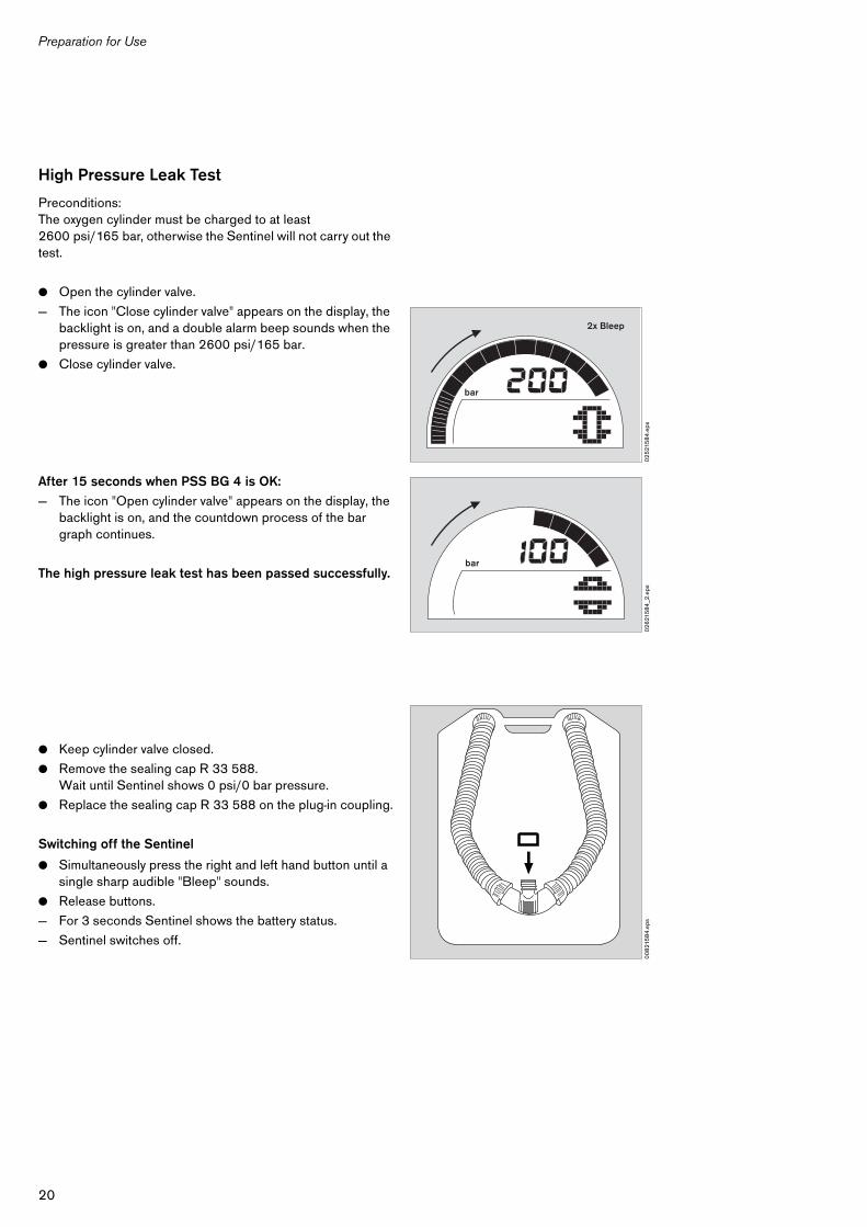
High Pressure Leak Test
Preconditions:The oxygen cylinder must be charged to at least2600 psi/165 bar, otherwise the Sentinel will not carry out the test.
● Open the cylinder valve.
— The icon "Close cylinder valve" appears on the display, the backlight is on, and a double alarm beep sounds when the pressure is greater than 2600 psi/165 bar.
● Close cylinder valve.
After 15 seconds when PSS BG 4 is OK:
— The icon "Open cylinder valve" appears on the display, the backlight is on, and the countdown process of the bar graph continues.
The high pressure leak test has been passed successfully.
● Keep cylinder valve closed.
● Remove the sealing cap R 33 588.Wait until Sentinel shows 0 psi/0 bar pressure.
● Replace the sealing cap R 33 588 on the plug-in coupling.
Switching off the Sentinel
● Simultaneously press the right and left hand button until a single sharp audible "Bleep" sounds.
● Release buttons.
— For 3 seconds Sentinel shows the battery status.
— Sentinel switches off.
02
521
58
4.e
ps
bar
2x Bleep
02
621
58
4_2
.eps
bar
00
821
58
4.e
ps
21
Preparation for Use
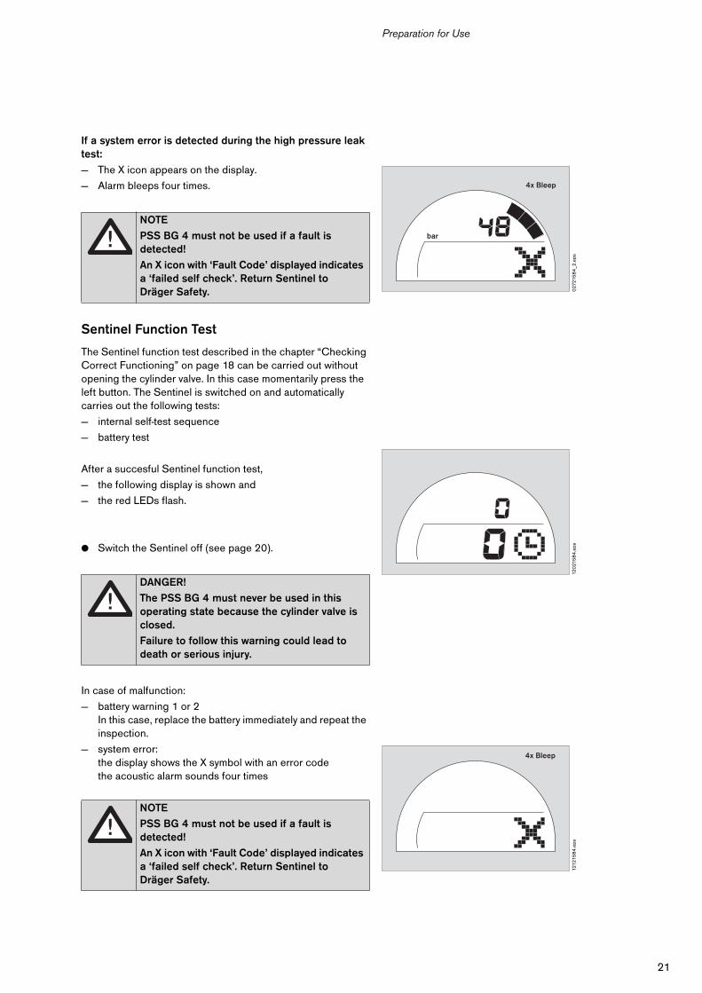
If a system error is detected during the high pressure leak test:
— The X icon appears on the display.
— Alarm bleeps four times.
Sentinel Function Test
The Sentinel function test described in the chapter “Checking Correct Functioning” on page 18 can be carried out without opening the cylinder valve. In this case momentarily press the left button. The Sentinel is switched on and automatically carries out the following tests:
— internal self-test sequence
— battery test
After a succesful Sentinel function test,
— the following display is shown and
— the red LEDs flash.
● Switch the Sentinel off (see page 20).
In case of malfunction:
— battery warning 1 or 2In this case, replace the battery immediately and repeat the inspection.
— system error:the display shows the X symbol with an error codethe acoustic alarm sounds four times
NOTE
PSS BG 4 must not be used if a fault is detected!
An X icon with ‘Fault Code’ displayed indicates a ‘failed self check’. Return Sentinel to Dräger Safety.
DANGER!
The PSS BG 4 must never be used in this operating state because the cylinder valve is closed.
Failure to follow this warning could lead to death or serious injury.
NOTE
PSS BG 4 must not be used if a fault is detected!
An X icon with ‘Fault Code’ displayed indicates a ‘failed self check’. Return Sentinel to Dräger Safety.
027
215
84
_2.e
ps
bar
4x Bleep
120
215
84
.eps
1212
158
4.e
ps
4x Bleep
22
Preparation for Use
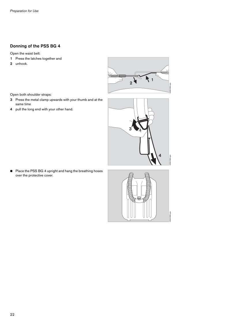
Donning of the PSS BG 4
Open the waist belt:
1 Press the latches together and
2 unhook.
Open both shoulder straps:
3 Press the metal clamp upwards with your thumb and at the same time
4 pull the long end with your other hand.
● Place the PSS BG 4 upright and hang the breathing hoses over the protective cover.
02
821
58
4.e
ps
12
02
921
58
4.e
ps4
3
03
021
58
4.e
ps
23
Preparation for Use
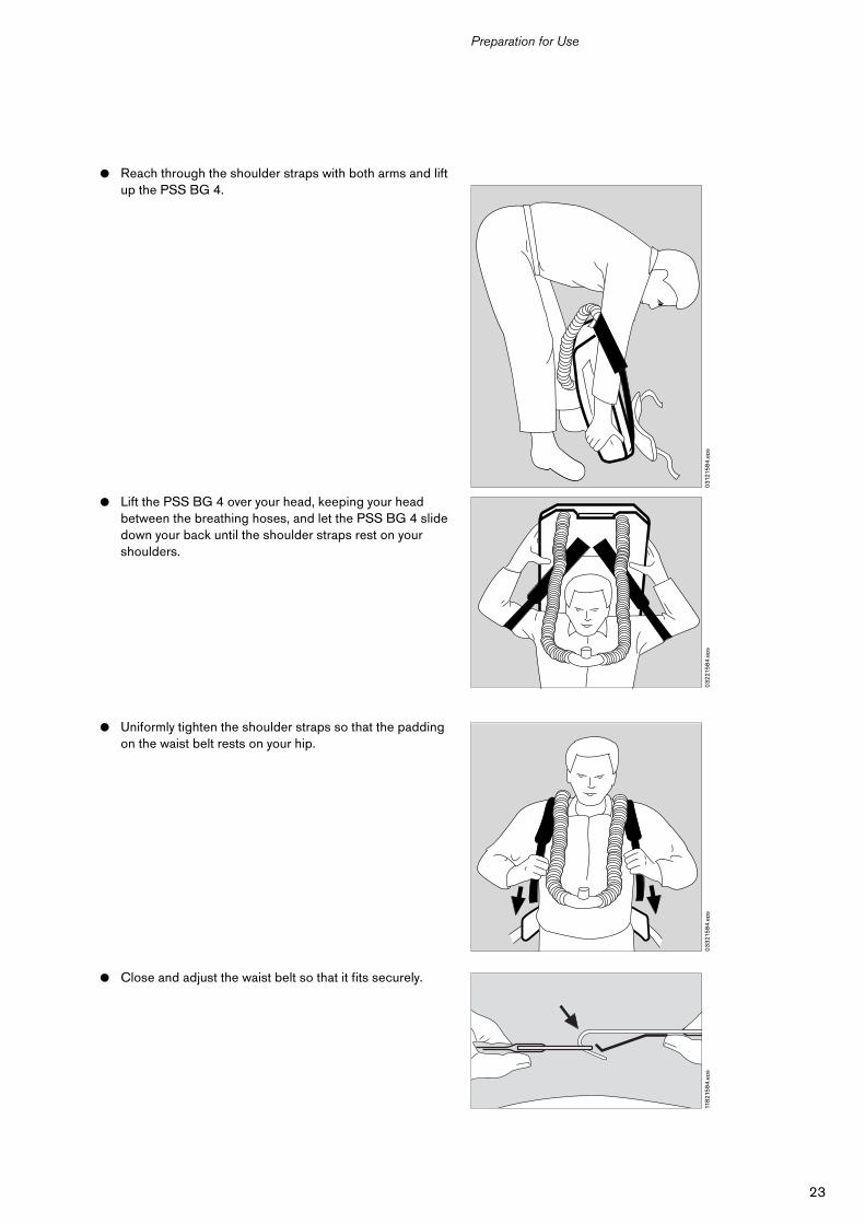
● Reach through the shoulder straps with both arms and lift up the PSS BG 4.
● Lift the PSS BG 4 over your head, keeping your head between the breathing hoses, and let the PSS BG 4 slide down your back until the shoulder straps rest on your shoulders.
● Uniformly tighten the shoulder straps so that the padding on the waist belt rests on your hip.
● Close and adjust the waist belt so that it fits securely.
031
215
84
.eps
03
221
58
4.e
ps0
33
215
84
.eps
118
215
84
.eps
24
Preparation for Use
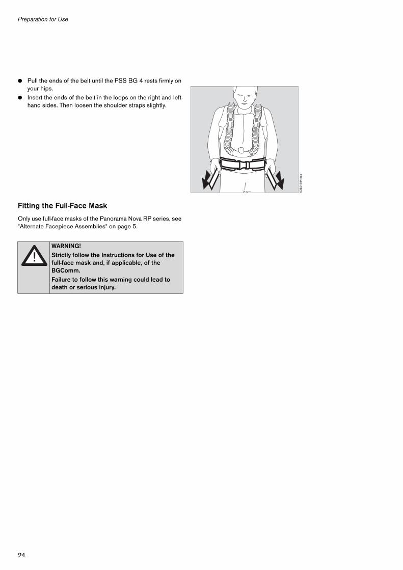
● Pull the ends of the belt until the PSS BG 4 rests firmly on your hips.
● Insert the ends of the belt in the loops on the right and left-hand sides. Then loosen the shoulder straps slightly.
Fitting the Full-Face Mask
Only use full-face masks of the Panorama Nova RP series, see "Alternate Facepiece Assemblies" on page 5.
WARNING!
Strictly follow the Instructions for Use of the full-face mask and, if applicable, of the BGComm.
Failure to follow this warning could lead to death or serious injury.
03
521
58
4.e
ps
25
Preparation for Use
Start-Up
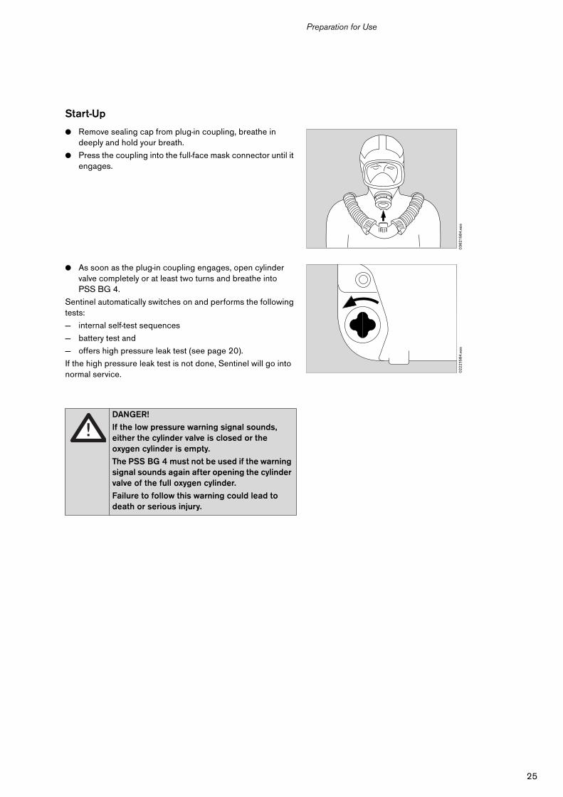
● Remove sealing cap from plug-in coupling, breathe in deeply and hold your breath.
● Press the coupling into the full-face mask connector until it engages.
● As soon as the plug-in coupling engages, open cylinder valve completely or at least two turns and breathe into PSS BG 4.
Sentinel automatically switches on and performs the following tests:
— internal self-test sequences
— battery test and
— offers high pressure leak test (see page 20).
If the high pressure leak test is not done, Sentinel will go into normal service.
DANGER!
If the low pressure warning signal sounds, either the cylinder valve is closed or the oxygen cylinder is empty.
The PSS BG 4 must not be used if the warning signal sounds again after opening the cylinder valve of the full oxygen cylinder.
Failure to follow this warning could lead to death or serious injury.
03
621
58
4.e
ps0
22
215
84
.eps
26
Preparation for Use
Checking Readiness for Use
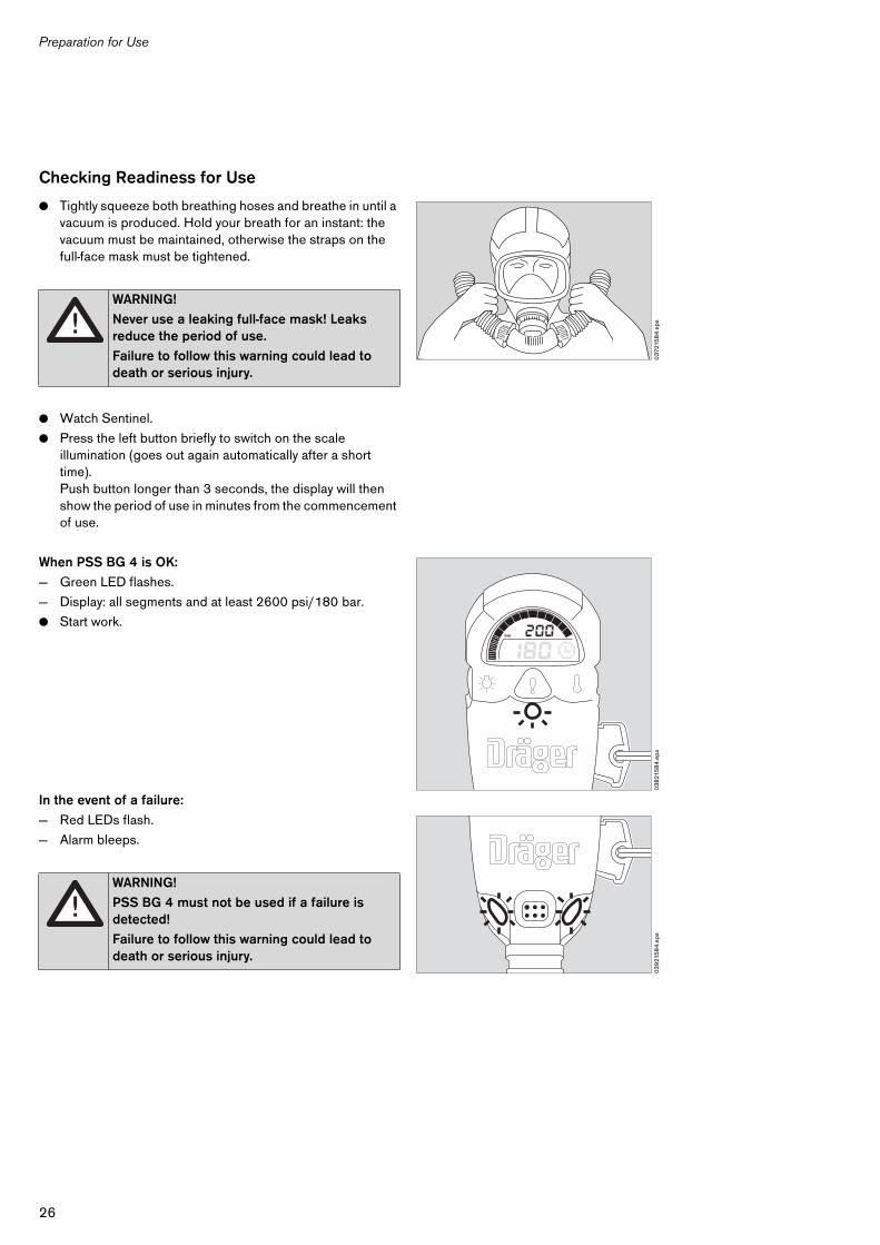
● Tightly squeeze both breathing hoses and breathe in until a vacuum is produced. Hold your breath for an instant: the vacuum must be maintained, otherwise the straps on the full-face mask must be tightened.
● Watch Sentinel.
● Press the left button briefly to switch on the scale illumination (goes out again automatically after a short time).Push button longer than 3 seconds, the display will then show the period of use in minutes from the commencement of use.
When PSS BG 4 is OK:
— Green LED flashes.
— Display: all segments and at least 2600 psi/180 bar.
● Start work.
In the event of a failure:
— Red LEDs flash.
— Alarm bleeps.
WARNING!
Never use a leaking full-face mask! Leaks reduce the period of use.
Failure to follow this warning could lead to death or serious injury.
WARNING!
PSS BG 4 must not be used if a failure is detected!
Failure to follow this warning could lead to death or serious injury.
037
215
84
.eps
03
821
58
4.e
ps
bar
03
921
58
4.e
ps
27
Practical Use
Practical Use
The PSS BG 4 operates fully automatically. Absorption of the CO2 generates heat which can be felt, particularly when working under aggravated conditions with intense breathing. This is perfectly normal and indicates that the PSS BG 4 is functioning correctly.
The period of service and retreat must be planned independently of the low pressure warnings. The mission must always be finished when the last low pressure warning output is at approx. 145 psi/10 bar.
In an Emergency
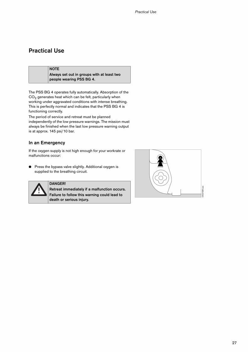
If the oxygen supply is not high enough for your workrate or malfunctions occur:
● Press the bypass valve slightly. Additional oxygen is supplied to the breathing circuit.
NOTE
Always set out in groups with at least two people wearing PSS BG 4.
DANGER!
Retreat immediately if a malfunction occurs.
Failure to follow this warning could lead to death or serious injury.
04
021
58
4.e
ps
28
Practical Use
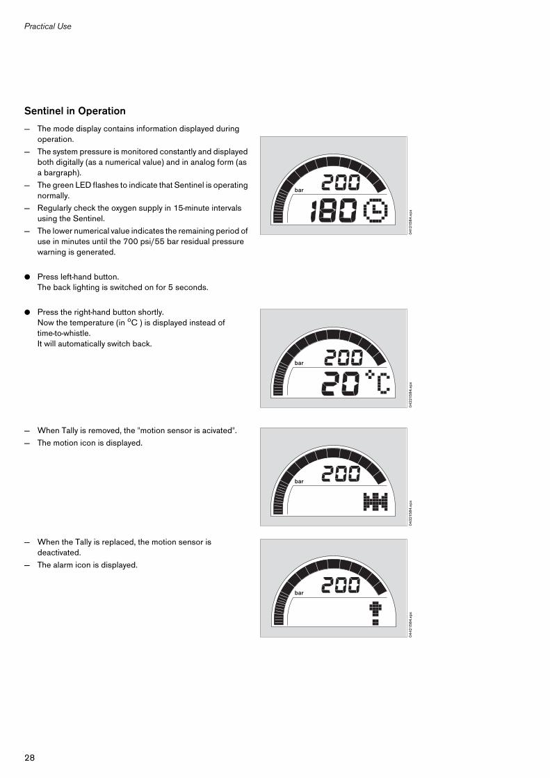
Sentinel in Operation
— The mode display contains information displayed during operation.
— The system pressure is monitored constantly and displayed both digitally (as a numerical value) and in analog form (as a bargraph).
— The green LED flashes to indicate that Sentinel is operating normally.
— Regularly check the oxygen supply in 15-minute intervals using the Sentinel.
— The lower numerical value indicates the remaining period of use in minutes until the 700 psi/55 bar residual pressure warning is generated.
● Press left-hand button.The back lighting is switched on for 5 seconds.
● Press the right-hand button shortly.Now the temperature (in oC ) is displayed instead oftime-to-whistle. It will automatically switch back.
— When Tally is removed, the "motion sensor is acivated".
— The motion icon is displayed.
— When the Tally is replaced, the motion sensor is deactivated.
— The alarm icon is displayed.
041
215
84
.eps
bar
04
221
58
4.e
ps
bar
04
321
58
4.e
ps
bar
04
421
58
4.e
ps
bar
29
Practical Use
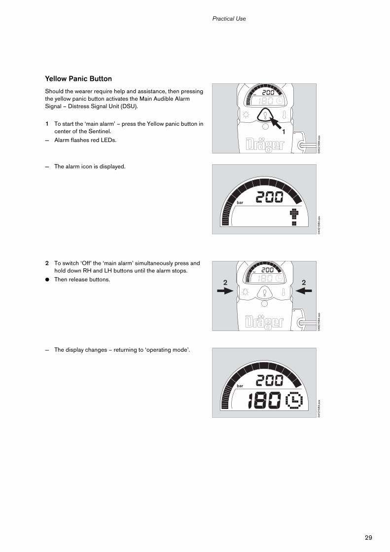
Yellow Panic Button
Should the wearer require help and assistance, then pressing the yellow panic button activates the Main Audible Alarm Signal – Distress Signal Unit (DSU).
1 To start the ‘main alarm’ – press the Yellow panic button in center of the Sentinel.
— Alarm flashes red LEDs.
— The alarm icon is displayed.
2 To switch ‘Off’ the ‘main alarm’ simultaneously press and hold down RH and LH buttons until the alarm stops.
● Then release buttons.
— The display changes – returning to ‘operating mode’.
04
521
58
4.e
ps
bar
1
04
421
58
4.e
ps
bar
04
621
58
4.e
ps
bar
22
041
215
84
.eps
bar
30
Practical Use
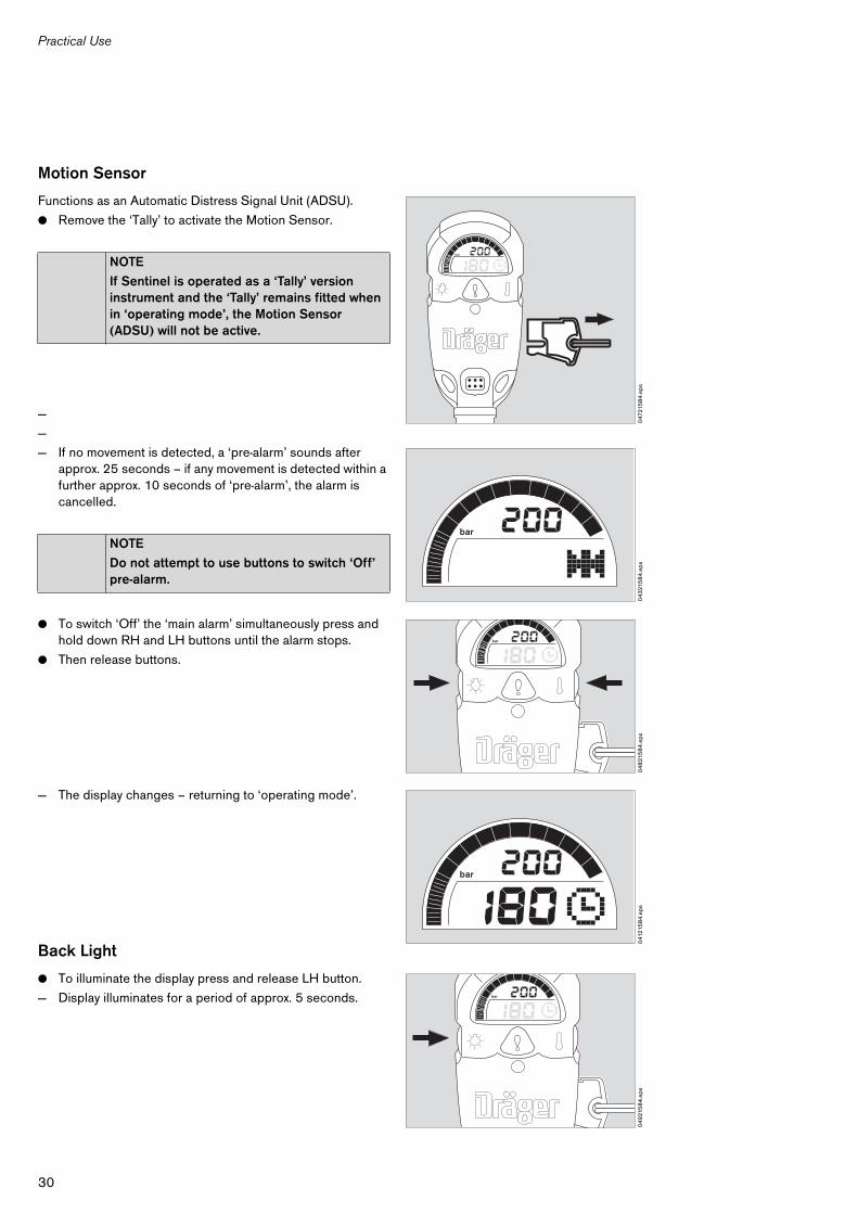
Motion Sensor
Functions as an Automatic Distress Signal Unit (ADSU).
● Remove the ‘Tally’ to activate the Motion Sensor.
—
—
— If no movement is detected, a ‘pre-alarm’ sounds after approx. 25 seconds – if any movement is detected within a further approx. 10 seconds of ‘pre-alarm’, the alarm is cancelled.
● To switch ‘Off’ the ‘main alarm’ simultaneously press and hold down RH and LH buttons until the alarm stops.
● Then release buttons.
— The display changes – returning to ‘operating mode’.
Back Light
● To illuminate the display press and release LH button.
— Display illuminates for a period of approx. 5 seconds.
NOTE
If Sentinel is operated as a ‘Tally’ version instrument and the ‘Tally’ remains fitted when in ‘operating mode’, the Motion Sensor (ADSU) will not be active.
NOTE
Do not attempt to use buttons to switch ‘Off’ pre-alarm.
047
215
84
.eps
bar
04
321
58
4.e
ps
bar
04
821
58
4.e
psbar
041
215
84
.eps
bar
04
921
58
4.e
ps
bar
31
Practical Use
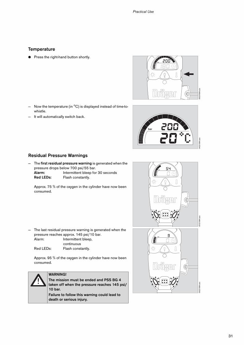
Temperature
● Press the right-hand button shortly.
— Now the temperature (in oC) is displayed instead of time-to-whistle.
— It will automatically switch back.
Residual Pressure Warnings
— The first residual pressure warning is generated when the pressure drops below 700 psi/55 bar.Alarm: Intermittent bleep for 30 secondsRed LEDs: Flash constantly.
Approx. 75 % of the oxygen in the cylinder have now been consumed.
— The last residual pressure warning is generated when the pressure reaches approx. 145 psi/10 bar.Alarm: Intermittent bleep,
continuousRed LEDs: Flash constantly.
Approx. 95 % of the oxygen in the cylinder have now been consumed.
WARNING!
The mission must be ended and PSS BG 4 taken off when the pressure reaches 145 psi/10 bar.
Failure to follow this warning could lead to death or serious injury.
05
021
58
4.e
ps
bar
04
221
58
4.e
ps
bar
051
215
84
.eps
bar
05
221
58
4.e
ps
bar
32
After Use
After Use
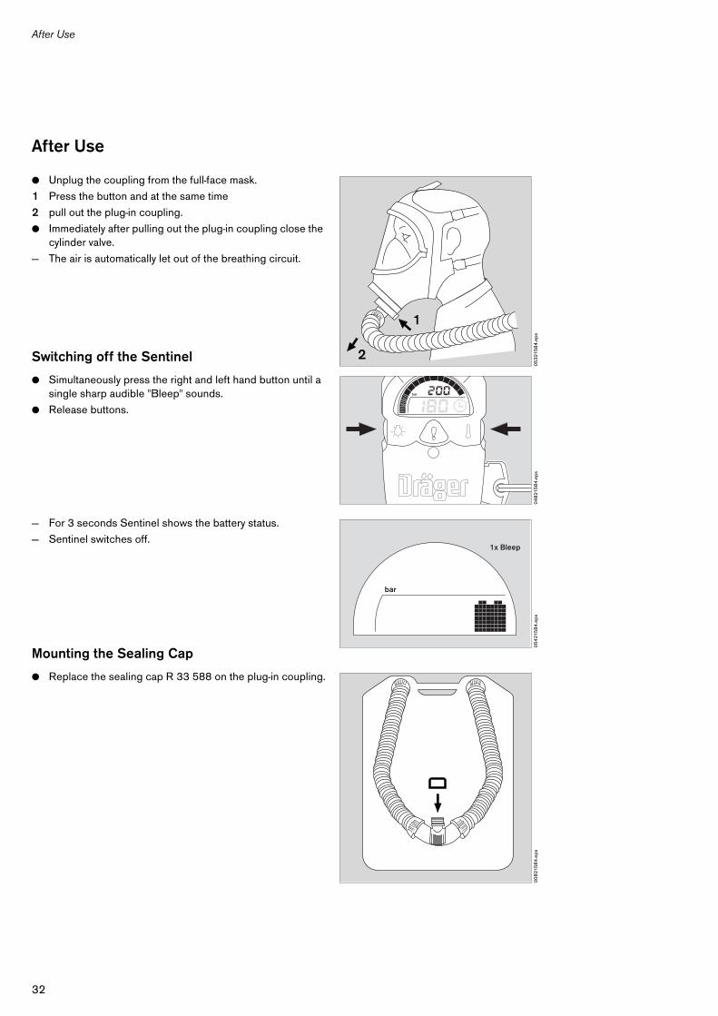
● Unplug the coupling from the full-face mask.
1 Press the button and at the same time
2 pull out the plug-in coupling.
● Immediately after pulling out the plug-in coupling close the cylinder valve.
— The air is automatically let out of the breathing circuit.
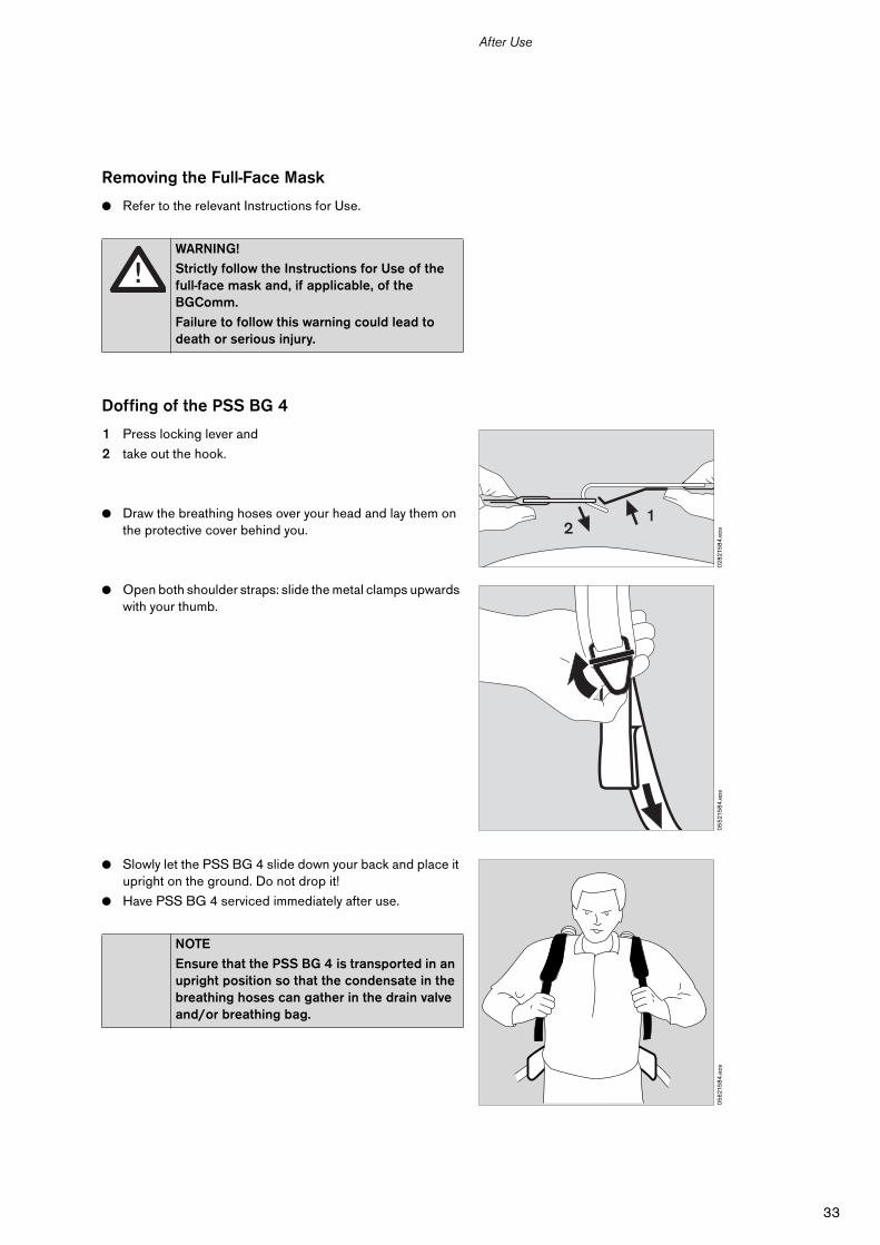
Switching off the Sentinel
● Simultaneously press the right and left hand button until a single sharp audible "Bleep" sounds.
● Release buttons.
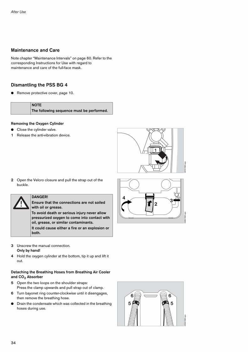
— For 3 seconds Sentinel shows the battery status.
— Sentinel switches off.
Mounting the Sealing Cap
● Replace the sealing cap R 33 588 on the plug-in coupling.
05
321
58
4.e
ps
1
2
04
821
58
4.e
ps
bar
05
421
58
4.e
ps
1x Bleep
bar
00
821
58
4.e
ps
33
After Use
Removing the Full-Face Mask
● Refer to the relevant Instructions for Use.
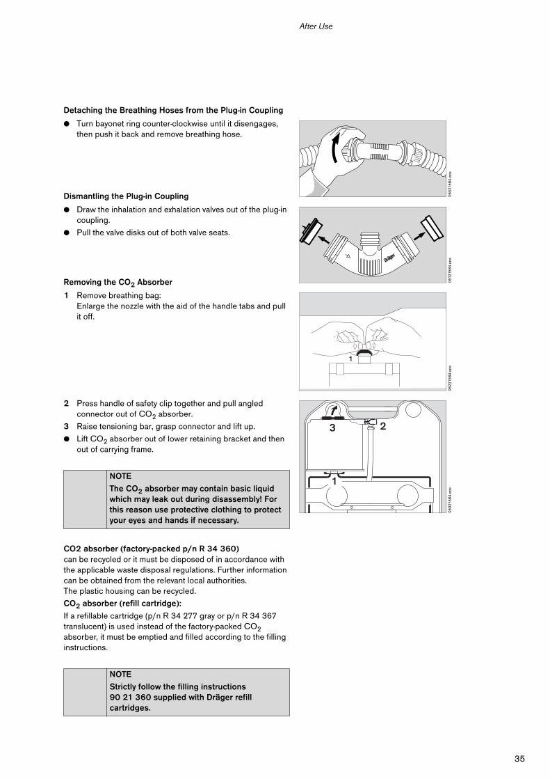
Doffing of the PSS BG 4
1 Press locking lever and
2 take out the hook.
● Draw the breathing hoses over your head and lay them on the protective cover behind you.
● Open both shoulder straps: slide the metal clamps upwards with your thumb.
● Slowly let the PSS BG 4 slide down your back and place it upright on the ground. Do not drop it!
● Have PSS BG 4 serviced immediately after use.
WARNING!
Strictly follow the Instructions for Use of the full-face mask and, if applicable, of the BGComm.
Failure to follow this warning could lead to death or serious injury.
NOTE
Ensure that the PSS BG 4 is transported in an upright position so that the condensate in the breathing hoses can gather in the drain valve and/or breathing bag.
02
821
58
4.e
ps
12
05
521
58
4.e
ps0
56
215
84
.eps
34
After Use
Maintenance and Care
Note chapter “Maintenance Intervals” on page 60. Refer to the corresponding Instructions for Use with regard to maintenance and care of the full-face mask.
Dismantling the PSS BG 4
● Remove protective cover, page 10.
Removing the Oxygen Cylinder
● Close the cylinder valve.
1 Release the anti-vibration device.
2 Open the Velcro closure and pull the strap out of the buckle.
3 Unscrew the manual connection.Only by hand!
4 Hold the oxygen cylinder at the bottom, tip it up and lift it out.
Detaching the Breathing Hoses from Breathing Air Cooler and CO2 Absorber
5 Open the two loops on the shoulder straps:Press the clamp upwards and pull strap out of clamp.
6 Turn bayonet ring counter-clockwise until it disengages, then remove the breathing hose.
● Drain the condensate which was collected in the breathing hoses during use.
NOTE
The following sequence must be performed.
DANGER!
Ensure that the connections are not soiled with oil or grease.
To avoid death or serious injury never allow pressurized oxygen to come into contact with oil, grease, or similar contaminants.
It could cause either a fire or an explosion or both.
057
215
84
.eps
1
05
821
58
4.e
ps
234
05
921
58
4.e
ps
5 5
6 6
35
After Use
Detaching the Breathing Hoses from the Plug-in Coupling
● Turn bayonet ring counter-clockwise until it disengages, then push it back and remove breathing hose.
Dismantling the Plug-in Coupling
● Draw the inhalation and exhalation valves out of the plug-in coupling.
● Pull the valve disks out of both valve seats.
Removing the CO2 Absorber
1 Remove breathing bag:Enlarge the nozzle with the aid of the handle tabs and pull it off.
2 Press handle of safety clip together and pull angled connector out of CO2 absorber.
3 Raise tensioning bar, grasp connector and lift up.
● Lift CO2 absorber out of lower retaining bracket and then out of carrying frame.
CO2 absorber (factory-packed p/n R 34 360)can be recycled or it must be disposed of in accordance with the applicable waste disposal regulations. Further information can be obtained from the relevant local authorities.The plastic housing can be recycled.
CO2 absorber (refill cartridge):
If a refillable cartridge (p/n R 34 277 gray or p/n R 34 367 translucent) is used instead of the factory-packed CO2 absorber, it must be emptied and filled according to the filling instructions.
NOTE
The CO2 absorber may contain basic liquid which may leak out during disassembly! For this reason use protective clothing to protect your eyes and hands if necessary.
NOTE
Strictly follow the filling instructions 90 21 360 supplied with Dräger refill cartridges.
06
021
58
4.e
ps0
6121
58
4.e
ps0
62
215
84
.eps
1
06
321
58
4.e
ps
3
1
2
36
After Use
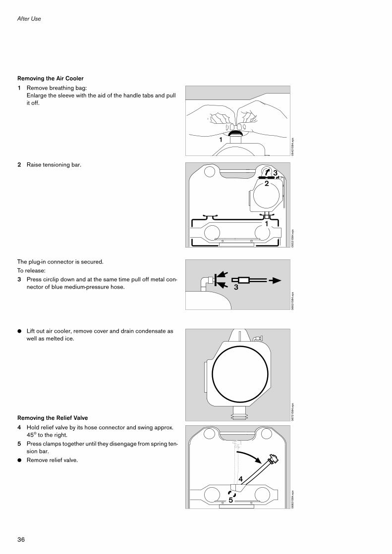
Removing the Air Cooler
1 Remove breathing bag:Enlarge the sleeve with the aid of the handle tabs and pull it off.
2 Raise tensioning bar.
The plug-in connector is secured.
To release:
3 Press circlip down and at the same time pull off metal con-nector of blue medium-pressure hose.
● Lift out air cooler, remove cover and drain condensate as well as melted ice.
Removing the Relief Valve
4 Hold relief valve by its hose connector and swing approx. 45o to the right.
5 Press clamps together until they disengage from spring ten-sion bar.
● Remove relief valve.
06
421
58
4.e
ps1
06
521
58
4.e
ps
1
23
06
621
58
4.e
ps3
067
215
84
.eps
06
821
58
4.e
ps
4
5
37
After Use
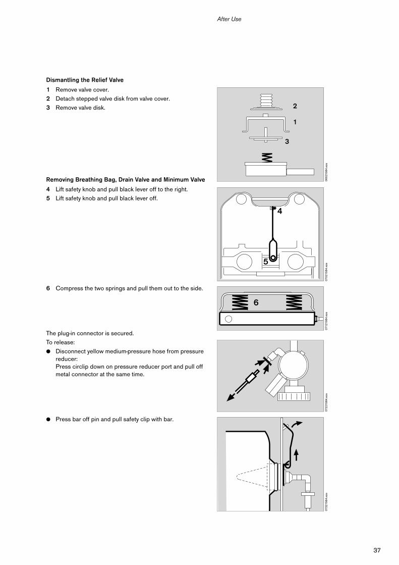
Dismantling the Relief Valve
1 Remove valve cover.
2 Detach stepped valve disk from valve cover.
3 Remove valve disk.
Removing Breathing Bag, Drain Valve and Minimum Valve
4 Lift safety knob and pull black lever off to the right.
5 Lift safety knob and pull black lever off.
6 Compress the two springs and pull them out to the side.
The plug-in connector is secured.
To release:
● Disconnect yellow medium-pressure hose from pressure reducer:Press circlip down on pressure reducer port and pull off metal connector at the same time.
● Press bar off pin and pull safety clip with bar.
06
921
58
4.e
ps
2
1
3
070
215
84
.eps
4
5
0712
158
4.e
ps
6
072
215
84
.eps
073
215
84
.eps
38
After Use
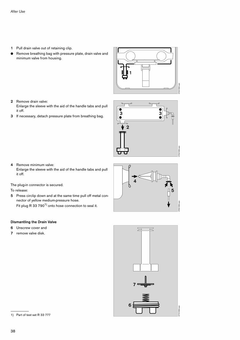
1 Pull drain valve out of retaining clip.
● Remove breathing bag with pressure plate, drain valve and minimum valve from housing.
2 Remove drain valve:Enlarge the sleeve with the aid of the handle tabs and pull it off.
3 If necessary, detach pressure plate from breathing bag.
4 Remove minimum valve:Enlarge the sleeve with the aid of the handle tabs and pull it off.
The plug-in connector is secured.
To release:
5 Press circlip down and at the same time pull off metal con-nector of yellow medium-pressure hose.
Fit plug R 33 7901) onto hose connection to seal it.
Dismantling the Drain Valve
6 Unscrew cover and
7 remove valve disk.
1) Part of test set R 33 777
074
215
84
.eps
1
075
215
84
.eps
2
3 3
076
215
84
.eps
4
5
0772
158
4.e
ps6
7
39
After Use
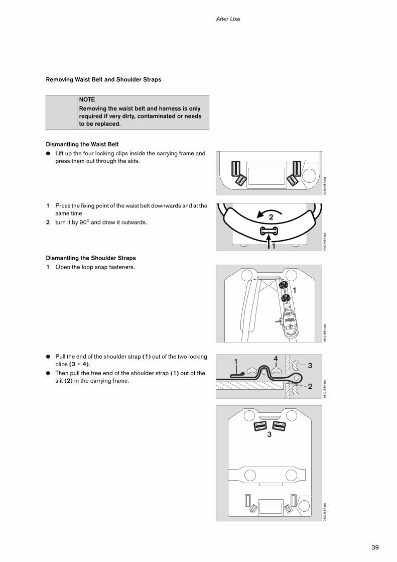
Removing Waist Belt and Shoulder Straps
Dismantling the Waist Belt
● Lift up the four locking clips inside the carrying frame and press them out through the slits.
1 Press the fixing point of the waist belt downwards and at the same time
2 turn it by 90o and draw it outwards.
Dismantling the Shoulder Straps
1 Open the loop snap fasteners.
● Pull the end of the shoulder strap (1) out of the two locking clips (3 + 4).
● Then pull the free end of the shoulder strap (1) out of the slit (2) in the carrying frame.
NOTE
Removing the waist belt and harness is only required if very dirty, contaminated or needs to be replaced.
078
215
84
.eps
079
215
84
.eps
2
1
08
021
58
4.e
ps
1
081
215
84
.eps
1 43
2
08
221
58
4.e
ps
3
40
After Use
Cleaning, Disinfection, Drying
All parts which get in contact with the exhaled air must be thoroughly cleaned and disinfected after use.
The other parts should only be cleaned if necessary.
Note the Instructions for Use of the full-face mask.
When contaminated with hazardous substances:
— Wear personal protective equipment.
— Dispose of rags and wastewater in accordance with the applicable waste disposal regulations.
Cleaning
All parts must be cleaned in lukewarm water with a mild detergent.
● Wipe the Switch Box and Sentinel with a damp cloth.
● Rinse in clear water. Detergent residues must be thoroughly rinsed off all parts of the PSS BG 4. We recommend that our hose rinsing set R 27 092 be used to rinse the breathing hoses and the breathing bag.
Disinfection
● Immerse the parts in the disinfectant bath using Multidor F®1), Incidur®2) or Airkem A-33™.
● Rinse thoroughly under running water.
Drying
Max. temperature 140 oF (60 oC).
We recommend our drying cabinet and our hose drying set R 41 120 for breathing hoses and breathing bag.
The belt and harness must be dried prior to storage to prevent growth of mold and fungus.
NOTE
Do not use organic solvents, such as acetone, trichloroethylene or similar solvents, or bleaches!
1) MFE Marienfelde GmbH, Nürnberg, Germany.2) Ecolab Inc. St. Paul, Minnesota 55102, USA.
CAUTION!
Strictly follow the Instructions for Use of the disinfectant.
High doses and long exposure times can damage the PSS BG 4 parts.
41
After Use
Charging the Oxygen Cylinder
The maximum charging pressure is 3135 psi/200 bar.
— The oxygen must have a purity >99.5 % and must be both tasteless and odourless.
— Permissible impurities in depressurized gas: Max. water vapor concentration: 50 mg/m3.
Assembling the PSS BG 4
All assembly operations should be checked on completion to ensure they are secured.
Proceed in the following order:
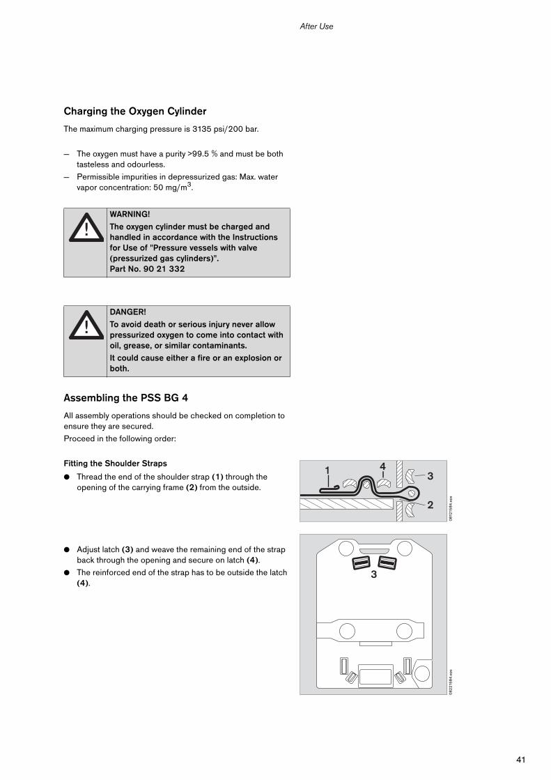
Fitting the Shoulder Straps
● Thread the end of the shoulder strap (1) through the opening of the carrying frame (2) from the outside.
● Adjust latch (3) and weave the remaining end of the strap back through the opening and secure on latch (4).
● The reinforced end of the strap has to be outside the latch (4).
WARNING!
The oxygen cylinder must be charged and handled in accordance with the Instructions for Use of "Pressure vessels with valve (pressurized gas cylinders)".Part No. 90 21 332
DANGER!
To avoid death or serious injury never allow pressurized oxygen to come into contact with oil, grease, or similar contaminants.
It could cause either a fire or an explosion or both.
081
215
84
.eps
1 43
2
08
221
58
4.e
ps
3
42
After Use
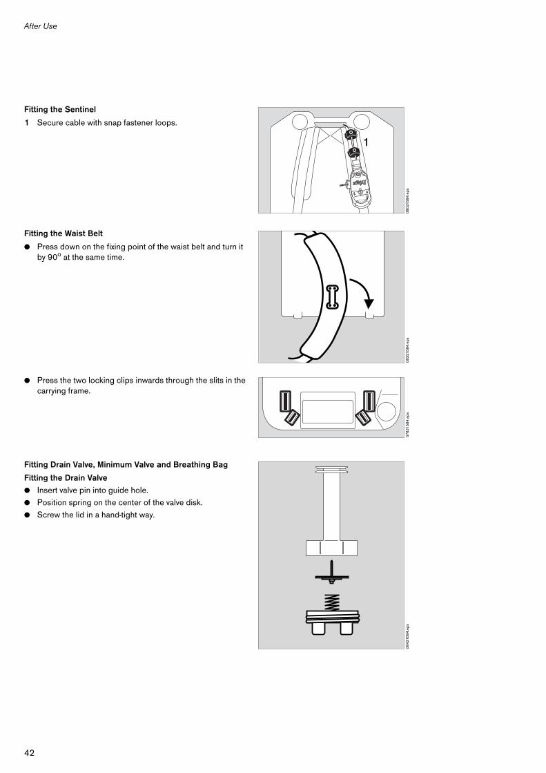
Fitting the Sentinel
1 Secure cable with snap fastener loops.
Fitting the Waist Belt
● Press down on the fixing point of the waist belt and turn it by 90o at the same time.
● Press the two locking clips inwards through the slits in the carrying frame.
Fitting Drain Valve, Minimum Valve and Breathing Bag
Fitting the Drain Valve
● Insert valve pin into guide hole.
● Position spring on the center of the valve disk.
● Screw the lid in a hand-tight way.
08
021
58
4.e
ps
1
08
321
58
4.e
ps07
821
58
4.e
ps0
84
215
84
.eps
43
After Use
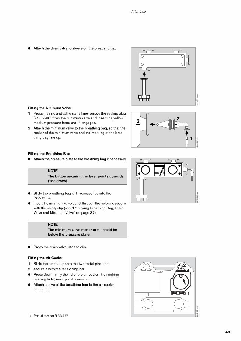
● Attach the drain valve to sleeve on the breathing bag.
Fitting the Minimum Valve
1 Press the ring and at the same time remove the sealing plug R 33 7901) from the minimum valve and insert the yellow medium-pressure hose until it engages.
2 Attach the minimum valve to the breathing bag, so that the rocker of the minimum valve and the marking of the brea-thing bag line up.
Fitting the Breathing Bag
● Attach the pressure plate to the breathing bag if necessary.
● Slide the breathing bag with accessories into the PSS BG 4.
● Insert the minimum valve outlet through the hole and secure with the safety clip (see “Removing Breathing Bag, Drain Valve and Minimum Valve” on page 37).
● Press the drain valve into the clip.
Fitting the Air Cooler
1 Slide the air cooler onto the two metal pins and
2 secure it with the tensioning bar.
● Press down firmly the lid of the air cooler, the marking (venting hole) must point upwards.
● Attach sleeve of the breathing bag to the air cooler connector.
1) Part of test set R 33 777
NOTE
The button securing the lever points upwards (see arrow).
NOTE
The minimum valve rocker arm should be below the pressure plate.
08
521
58
4.e
ps0
86
215
84
.eps
2
1
2
087
215
84
.eps
08
821
58
4.e
ps
1
2
44
After Use
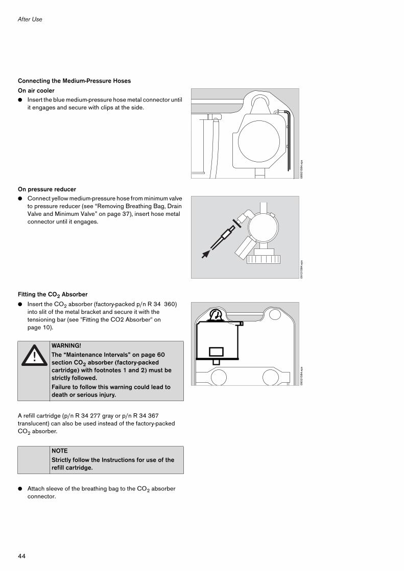
Connecting the Medium-Pressure Hoses
On air cooler
● Insert the blue medium-pressure hose metal connector until it engages and secure with clips at the side.
On pressure reducer
● Connect yellow medium-pressure hose from minimum valve to pressure reducer (see “Removing Breathing Bag, Drain Valve and Minimum Valve” on page 37), insert hose metal connector until it engages.
Fitting the CO2 Absorber
● Insert the CO2 absorber (factory-packed p/n R 34 360) into slit of the metal bracket and secure it with the tensioning bar (see "Fitting the CO2 Absorber" on page 10).
A refill cartridge (p/n R 34 277 gray or p/n R 34 367 translucent) can also be used instead of the factory-packed CO2 absorber.
● Attach sleeve of the breathing bag to the CO2 absorber connector.
WARNING!
The “Maintenance Intervals” on page 60 section CO2 absorber (factory-packed cartridge) with footnotes 1 and 2) must be strictly followed.
Failure to follow this warning could lead to death or serious injury.
NOTE
Strictly follow the Instructions for use of the refill cartridge.
08
921
58
4.e
ps0
9121
58
4.e
ps0
90
215
84
.eps
45
After Use
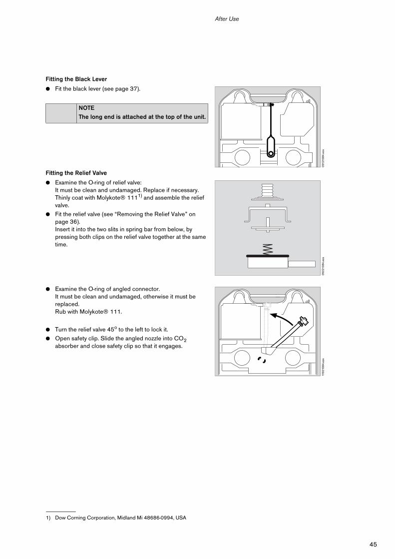
Fitting the Black Lever
● Fit the black lever (see page 37).
Fitting the Relief Valve
● Examine the O-ring of relief valve:It must be clean and undamaged. Replace if necessary.Thinly coat with Molykote® 1111) and assemble the relief valve.
● Fit the relief valve (see “Removing the Relief Valve” on page 36).Insert it into the two slits in spring bar from below, by pressing both clips on the relief valve together at the same time.
● Examine the O-ring of angled connector.It must be clean and undamaged, otherwise it must be replaced.Rub with Molykote® 111.
● Turn the relief valve 45o to the left to lock it.
● Open safety clip. Slide the angled nozzle into CO2 absorber and close safety clip so that it engages.
NOTE
The long end is attached at the top of the unit.
1) Dow Corning Corporation, Midland Mi 48686-0994, USA
091
215
84
.eps
09
221
58
4.e
ps11
921
58
4.e
ps
46
After Use
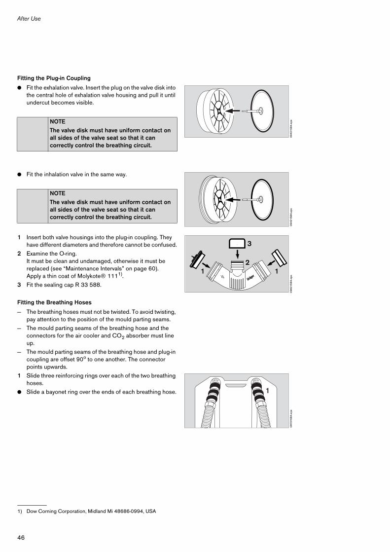
Fitting the Plug-in Coupling
● Fit the exhalation valve. Insert the plug on the valve disk into the central hole of exhalation valve housing and pull it until undercut becomes visible.
● Fit the inhalation valve in the same way.
1 Insert both valve housings into the plug-in coupling. They have different diameters and therefore cannot be confused.
2 Examine the O-ring.It must be clean and undamaged, otherwise it must be replaced (see “Maintenance Intervals” on page 60).Apply a thin coat of Molykote® 1111).
3 Fit the sealing cap R 33 588.
Fitting the Breathing Hoses
— The breathing hoses must not be twisted. To avoid twisting, pay attention to the position of the mould parting seams.
— The mould parting seams of the breathing hose and the connectors for the air cooler and CO2 absorber must line up.
— The mould parting seams of the breathing hose and plug-in coupling are offset 90o to one another. The connector points upwards.
1 Slide three reinforcing rings over each of the two breathing hoses.
● Slide a bayonet ring over the ends of each breathing hose.
NOTE
The valve disk must have uniform contact on all sides of the valve seat so that it can correctly control the breathing circuit.
NOTE
The valve disk must have uniform contact on all sides of the valve seat so that it can correctly control the breathing circuit.
1) Dow Corning Corporation, Midland Mi 48686-0994, USA
094
215
84
.eps
094
215
84
.eps
09
621
58
4.e
ps
1 1
3
2
097
215
84
.eps
1
47
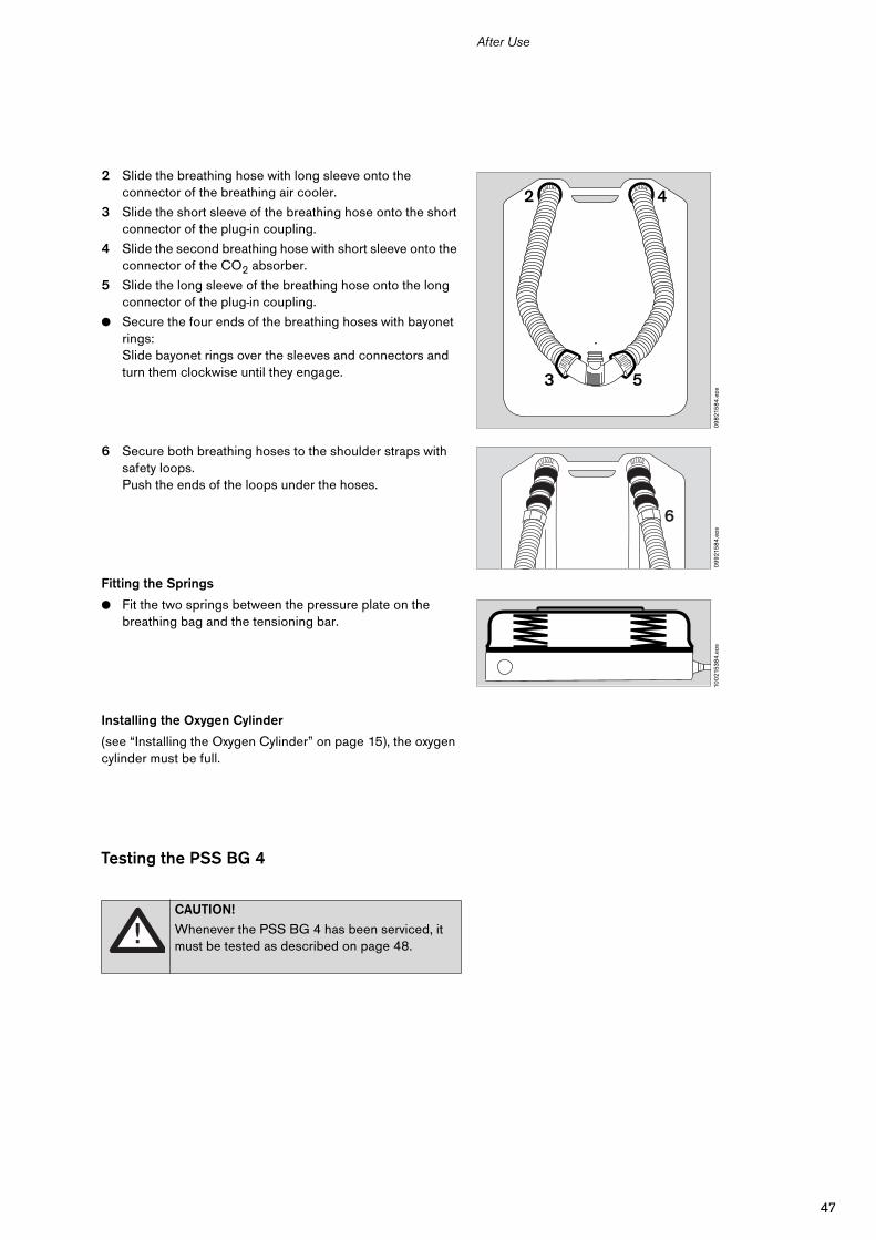
After Use
2 Slide the breathing hose with long sleeve onto the connector of the breathing air cooler.
3 Slide the short sleeve of the breathing hose onto the short connector of the plug-in coupling.
4 Slide the second breathing hose with short sleeve onto the connector of the CO2 absorber.
5 Slide the long sleeve of the breathing hose onto the long connector of the plug-in coupling.
● Secure the four ends of the breathing hoses with bayonet rings:Slide bayonet rings over the sleeves and connectors and turn them clockwise until they engage.
6 Secure both breathing hoses to the shoulder straps with safety loops. Push the ends of the loops under the hoses.
Fitting the Springs
● Fit the two springs between the pressure plate on the breathing bag and the tensioning bar.
Installing the Oxygen Cylinder
(see “Installing the Oxygen Cylinder” on page 15), the oxygen cylinder must be full.
Testing the PSS BG 4
CAUTION!
Whenever the PSS BG 4 has been serviced, it must be tested as described on page 48.
09
821
58
4.e
ps
3 5
2 4
09
921
58
4.e
ps
6
100
215
38
4.e
ps
48
Testing
Testing
Before starting up for the first time and whenever the PSS BG 4 has been serviced.
Testing the PSS BG 4 with Inserted CO2 Absorber
During the shelf life of the apparatus (see table “Maintenance Intervals” on page 60, section CO2 absorber (factory-packed cartridge) with footnotes 1 and 2) the operating test can be run a total of six times, each test lasting no more than 15 minutes.
A record of each test should be made on the CO2 absorber housing, with details of the month and year and the tester’s initials.
Exceptionally, if the breathing circuit is opened for more than 5 minutes, the CO2 absorber apertures should be sealed with three PE plugs to prevent escape of gas.
Test Equipment and Accessories
Additional Test Equipment by Dräger
Preparing for Tests
● Align the zero point of test unit Rz 25. Note the Instructions for Use of the test unit Rz 25.
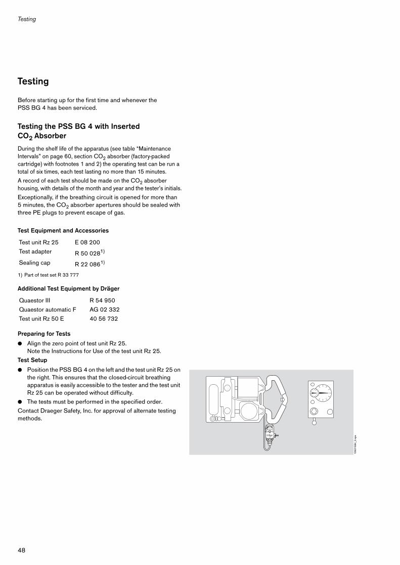
Test Setup
● Position the PSS BG 4 on the left and the test unit Rz 25 on the right. This ensures that the closed-circuit breathing apparatus is easily accessible to the tester and the test unit Rz 25 can be operated without difficulty.
● The tests must be performed in the specified order.
Contact Draeger Safety, Inc. for approval of alternate testing methods.
Test unit Rz 25 E 08 200
Test adapter R 50 0281)
1) Part of test set R 33 777
Sealing cap R 22 0861)
Quaestor III R 54 950
Quaestor automatic F AG 02 332
Test unit Rz 50 E 40 56 732
126
215
84
_2.e
ps
49
Testing
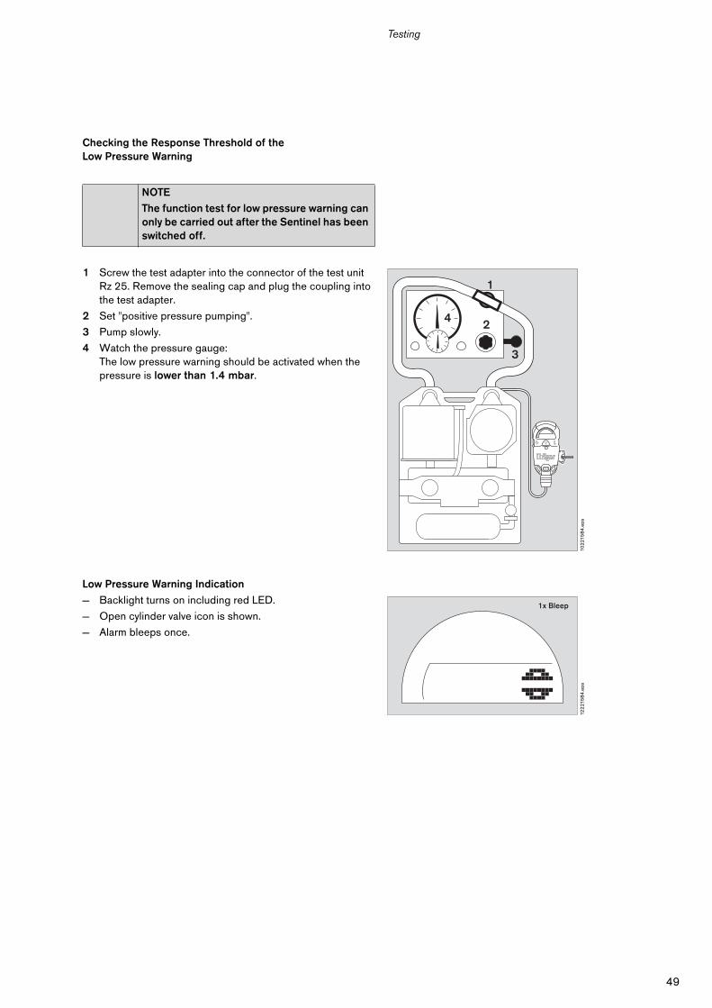
Checking the Response Threshold of the Low Pressure Warning
1 Screw the test adapter into the connector of the test unit Rz 25. Remove the sealing cap and plug the coupling into the test adapter.
2 Set "positive pressure pumping".
3 Pump slowly.
4 Watch the pressure gauge:The low pressure warning should be activated when the pressure is lower than 1.4 mbar.
Low Pressure Warning Indication
— Backlight turns on including red LED.
— Open cylinder valve icon is shown.
— Alarm bleeps once.
NOTE
The function test for low pressure warning can only be carried out after the Sentinel has been switched off.
102
215
84
.eps
4
3
2
1
122
215
84
.eps
1x Bleep
50
Testing
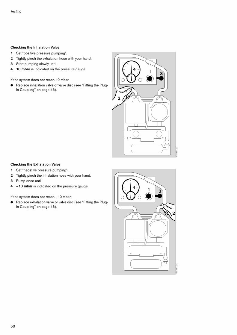
Checking the Inhalation Valve
1 Set "positive pressure pumping".
2 Tightly pinch the exhalation hose with your hand.
3 Start pumping slowly until
4 10 mbar is indicated on the pressure gauge.
If the system does not reach 10 mbar:
● Replace inhalation valve or valve disc (see “Fitting the Plug-in Coupling” on page 46).
Checking the Exhalation Valve
1 Set "negative pressure pumping".
2 Tightly pinch the inhalation hose with your hand.
3 Pump once until
4 –10 mbar is indicated on the pressure gauge.
If the system does not reach –10 mbar:
● Replace exhalation valve or valve disc (see “Fitting the Plug-in Coupling” on page 46).
104
215
84
.eps
4 1
2
3
105
215
84
.eps
1 34
2
51
Testing
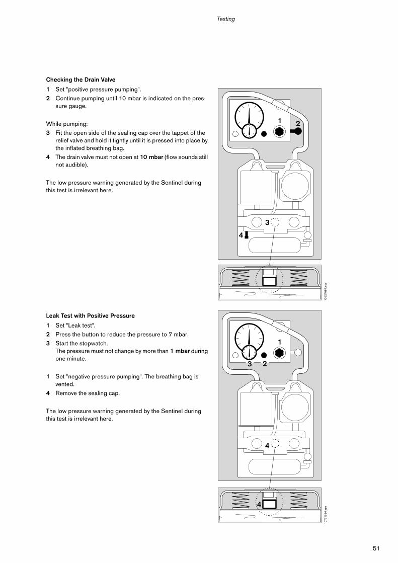
Checking the Drain Valve
1 Set "positive pressure pumping".
2 Continue pumping until 10 mbar is indicated on the pres-sure gauge.
While pumping:
3 Fit the open side of the sealing cap over the tappet of the relief valve and hold it tightly until it is pressed into place by the inflated breathing bag.
4 The drain valve must not open at 10 mbar (flow sounds still not audible).
The low pressure warning generated by the Sentinel during this test is irrelevant here.
Leak Test with Positive Pressure
1 Set "Leak test".
2 Press the button to reduce the pressure to 7 mbar.
3 Start the stopwatch.The pressure must not change by more than 1 mbar during one minute.
1 Set "negative pressure pumping". The breathing bag is vented.
4 Remove the sealing cap.
The low pressure warning generated by the Sentinel during this test is irrelevant here.
106
215
84
.eps
1 2
3
4
1072
158
4.e
ps
1
3 2
4
4
52
Testing
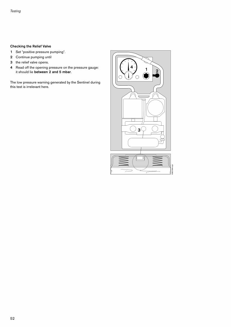
Checking the Relief Valve
1 Set "positive pressure pumping".
2 Continue pumping until
3 the relief valve opens.
4 Read off the opening pressure on the pressure gauge:it should lie between 2 and 5 mbar.
The low pressure warning generated by the Sentinel during this test is irrelevant here.
108
215
84
.eps
1
3
24
53
Testing
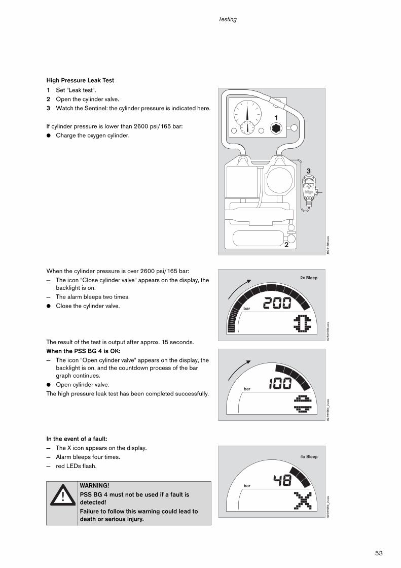
High Pressure Leak Test
1 Set "Leak test".
2 Open the cylinder valve.
3 Watch the Sentinel: the cylinder pressure is indicated here.
If cylinder pressure is lower than 2600 psi/165 bar:
● Charge the oxygen cylinder.
When the cylinder pressure is over 2600 psi/165 bar:
— The icon "Close cylinder valve" appears on the display, the backlight is on.
— The alarm bleeps two times.
● Close the cylinder valve.
The result of the test is output after approx. 15 seconds.
When the PSS BG 4 is OK:
— The icon "Open cylinder valve" appears on the display, the backlight is on, and the countdown process of the bar graph continues.
● Open cylinder valve.
The high pressure leak test has been completed successfully.
In the event of a fault:
— The X icon appears on the display.
— Alarm bleeps four times.
— red LEDs flash.
WARNING!
PSS BG 4 must not be used if a fault is detected!
Failure to follow this warning could lead to death or serious injury.
109
215
84
.eps
3
1
2
02
521
58
4.e
ps
bar
2x Bleep
02
621
58
4_2
.eps
bar
027
215
84
_2.e
ps
bar
4x Bleep
54
Testing
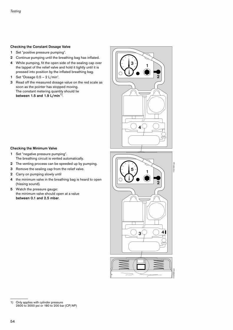
Checking the Constant Dosage Valve
1 Set "positive pressure pumping".
2 Continue pumping until the breathing bag has inflated.
4 While pumping, fit the open side of the sealing cap over the tappet of the relief valve and hold it tightly until it is pressed into position by the inflated breathing bag.
1 Set "Dosage 0.5 – 2 L/min".
3 Read off the measured dosage value on the red scale as soon as the pointer has stopped moving.The constant metering quantity should lie between 1.5 and 1.9 L/min1).
Checking the Minimum Valve
1 Set "negative pressure pumping". The breathing circuit is vented automatically.
2 The venting process can be speeded up by pumping.
3 Remove the sealing cap from the relief valve.
2 Carry on pumping slowly until
4 the minimum valve in the breathing bag is heard to open (hissing sound).
5 Watch the pressure gauge: the minimum valve should open at a value between 0.1 and 2.5 mbar.
1) Only applies with cylinder pressure 2600 to 3000 psi or 180 to 200 bar (CP/AP)
110
215
84
.eps
1
4
2
3
1112
158
4.e
ps1
3
2
5
4
55
Testing
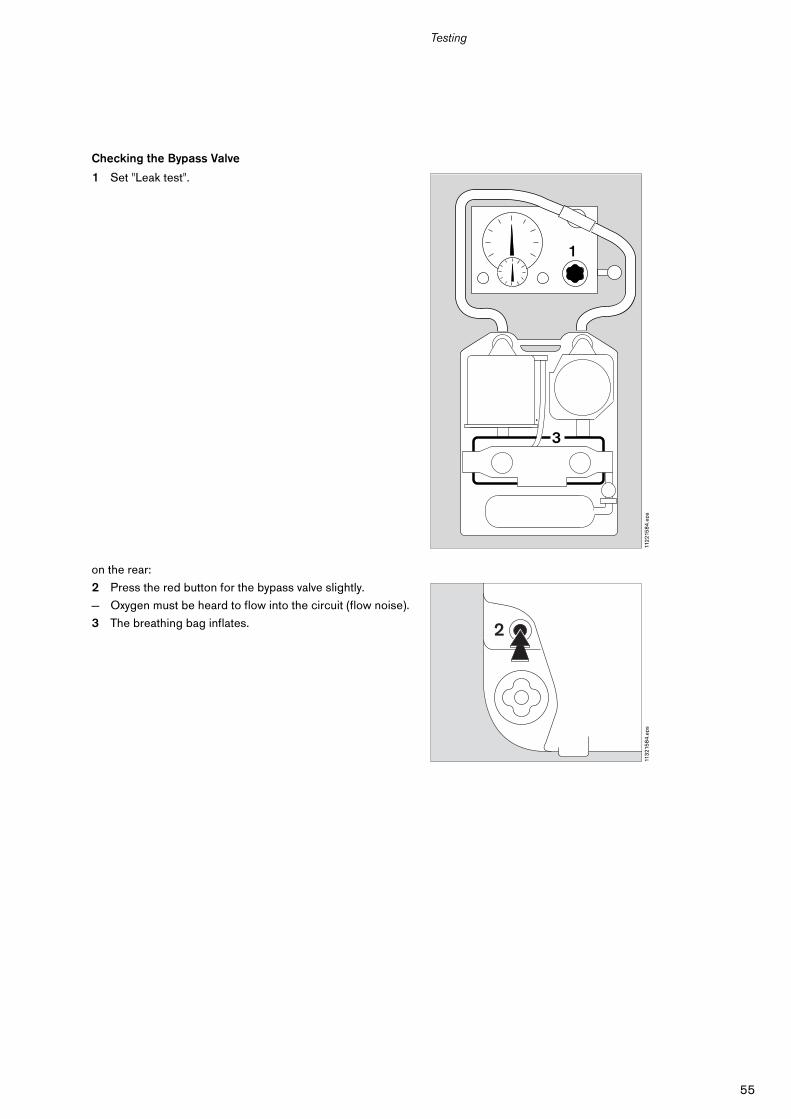
Checking the Bypass Valve
1 Set "Leak test".
on the rear:
2 Press the red button for the bypass valve slightly.
— Oxygen must be heard to flow into the circuit (flow noise).
3 The breathing bag inflates.
112
215
84
.eps
3
1
2
1
3
113
215
84
.eps
2
56
Testing
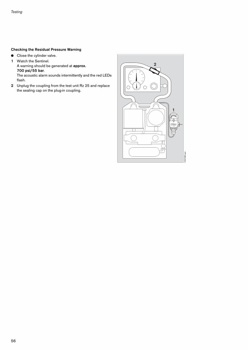
Checking the Residual Pressure Warning
● Close the cylinder valve.
1 Watch the Sentinel. A warning should be generated at approx.700 psi/55 bar.The acoustic alarm sounds intermittently and the red LEDs flash.
2 Unplug the coupling from the test unit Rz 25 and replace the sealing cap on the plug-in coupling.
112
215
84
.eps
1
2
57
Testing
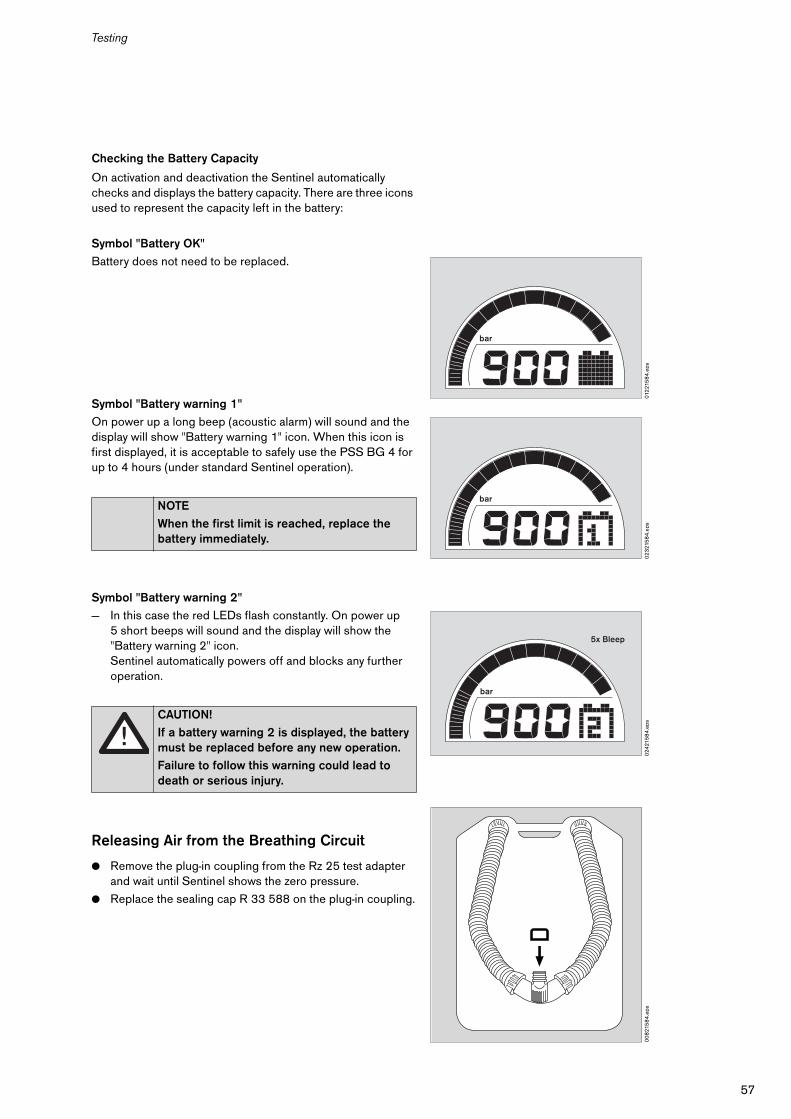
Checking the Battery Capacity
On activation and deactivation the Sentinel automatically checks and displays the battery capacity. There are three icons used to represent the capacity left in the battery:
Symbol "Battery OK"
Battery does not need to be replaced.
Symbol "Battery warning 1"
On power up a long beep (acoustic alarm) will sound and the display will show "Battery warning 1" icon. When this icon is first displayed, it is acceptable to safely use the PSS BG 4 for up to 4 hours (under standard Sentinel operation).
Symbol "Battery warning 2"
— In this case the red LEDs flash constantly. On power up 5 short beeps will sound and the display will show the "Battery warning 2" icon.Sentinel automatically powers off and blocks any further operation.
Releasing Air from the Breathing Circuit
● Remove the plug-in coupling from the Rz 25 test adapter and wait until Sentinel shows the zero pressure.
● Replace the sealing cap R 33 588 on the plug-in coupling.
NOTE
When the first limit is reached, replace the battery immediately.
CAUTION!
If a battery warning 2 is displayed, the battery must be replaced before any new operation.
Failure to follow this warning could lead to death or serious injury.
012
215
84
.eps
bar
02
321
58
4.e
ps
bar
024
215
84
.eps
bar
5x Bleep0
08
215
84
.eps
58
Testing
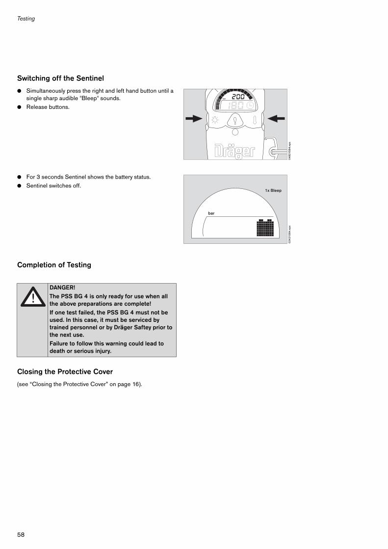
Switching off the Sentinel
● Simultaneously press the right and left hand button until a single sharp audible "Bleep" sounds.
● Release buttons.
● For 3 seconds Sentinel shows the battery status.
● Sentinel switches off.
Completion of Testing
Closing the Protective Cover
(see “Closing the Protective Cover” on page 16).
DANGER!
The PSS BG 4 is only ready for use when all the above preparations are complete!
If one test failed, the PSS BG 4 must not be used. In this case, it must be serviced by trained personnel or by Dräger Saftey prior to the next use.
Failure to follow this warning could lead to death or serious injury.
04
821
58
4.e
ps
bar
024
215
84
.eps
1x Bleep
bar
59
Storage
Storage
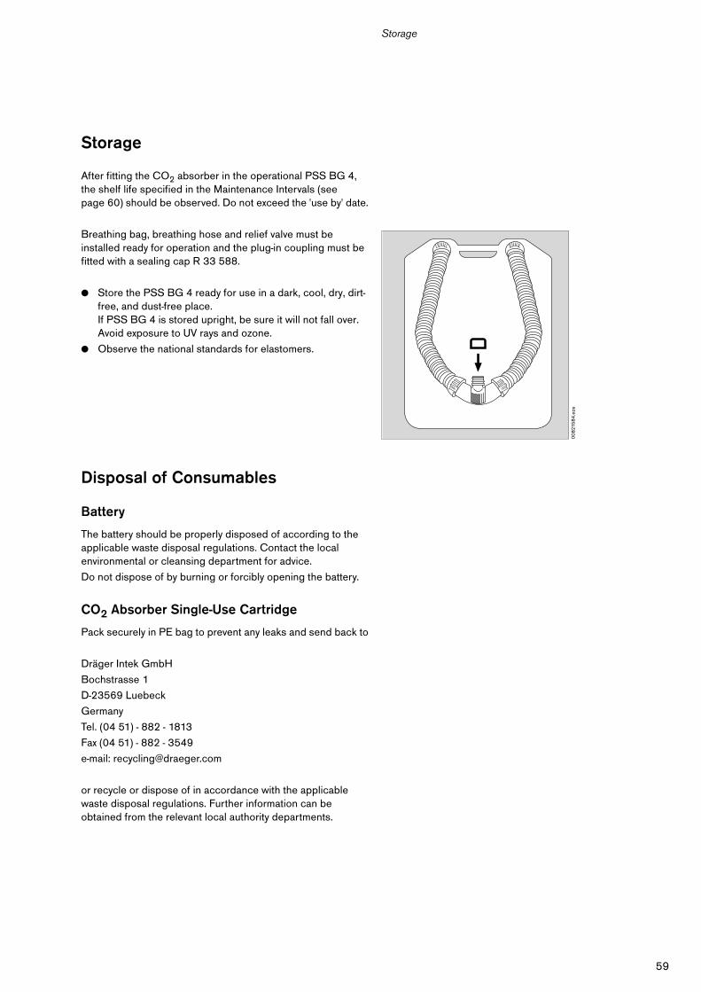
After fitting the CO2 absorber in the operational PSS BG 4, the shelf life specified in the Maintenance Intervals (see page 60) should be observed. Do not exceed the 'use by' date.
Breathing bag, breathing hose and relief valve must be installed ready for operation and the plug-in coupling must be fitted with a sealing cap R 33 588.
● Store the PSS BG 4 ready for use in a dark, cool, dry, dirt-free, and dust-free place.If PSS BG 4 is stored upright, be sure it will not fall over.Avoid exposure to UV rays and ozone.
● Observe the national standards for elastomers.
Disposal of Consumables
Battery
The battery should be properly disposed of according to the applicable waste disposal regulations. Contact the local environmental or cleansing department for advice.
Do not dispose of by burning or forcibly opening the battery.
CO2 Absorber Single-Use Cartridge
Pack securely in PE bag to prevent any leaks and send back to
Dräger Intek GmbH
Bochstrasse 1
D-23569 Luebeck
Germany
Tel. (04 51) - 882 - 1813
Fax (04 51) - 882 - 3549
e-mail: [email protected]
or recycle or dispose of in accordance with the applicable waste disposal regulations. Further information can be obtained from the relevant local authority departments.
00
821
58
4.e
ps
60
Maintenance Intervals
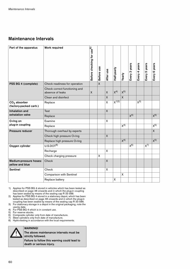
Maintenance Intervals
1) Applies for PSS BG 4 stored in vehicles which has been tested as described on page 48 onwards and in which the plug-in coupling has been sealed by means of the sealing cap R 33 588.
2) Applies for PSS BG 4 stored in a stationary depot, which has been tested as described on page 48 onwards and in which the plug-in coupling has been sealed by means of the sealing cap R 33 588.
3) For stationary storage in a depot in the original packaging, note the use-by date.
4) For PSS BG 4 which is in constant use.5) For reserve stocks.6) Composite cylinder only from date of manufacture.7) Steel cylinders only from date of manufacture.8) Hydro-testing in accordance with the local requirements.
Part of the apparatus Work required
Bef
ore
che
ckin
g f
or
use6
)
Bef
ore
use
Aft
er u
se
Hal
f-yea
rly
Year
ly
Eve
ry 3
yea
rs
Eve
ry 4
yea
rs
Eve
ry 5
yea
rs
Eve
ry 6
yea
rs
PSS BG 4 (complete) Check readiness for operation X
Check correct functioning andabsence of leaks X X X4) X5)
Clean and disinfect X X
CO2 absorber (factory-packed cartr.)
Replace X X1)2) X3)
Inhalation and exhalation valve
Test X
Replace X4) X5)
O-ring onplug-in coupling
Examine X
Replace X4) X5)
Pressure reducer Thorough overhaul by experts X
Check high pressure O-ring X
Replace high pressure O-ring X4) X5)
Oxygen cylinder U.S.DOT8) X6) X7)
Recharge X
Check charging pressure X
Medium-pressure hoses:yellow and blue
Check X
Sentinel Check X
Comparison with Sentinel X
Replace battery X
WARNING!
The above maintenance intervals must be strictly followed.
Failure to follow this warning could lead to death or serious injury.
61
Technical Data
Technical Data
Ambient conditions
Operation
Minimumpermissible temperature 23 oF (–5 oC)
Minimum temperature of 5 oF (–15 oC) is permissible if the PSS BG 4 is stored in a temperature range of 59 oF to 77 oF (15 oC to 25 oC)
Maximumtemperature ranges limit the period of use for PSS BG 4 Dräger recommends under
moderate service conditions:
For temperatures of up to 104 oF (40 oC) the period of use is up to 4 hours with ice in cooler1).
For temperatures of 105 oF to 140 oF (41 oC to 60 oC) the period of use is 1 hour with ice in cooler1).
For temperatures of 141 oF to 194 oF (61 oC to 90 oC) the period of use is 15 minutes with ice in cooler1).
Air pressure 900 hPa to 1200 hPa
Rel. humidity 0 % to 100 %
Storage
Temperature 23 oF to 77 oF(–5 oC to 25 oC)
Air pressure 900 hPa to 1200 hPa
Rel. humidity 30 % to 70 %
PSS BG 4 characteristics
The USA use the PSS BG 4 AP.
The period of usewith oxygen cylinder steel R 27 082 is 4 hours,with oxygen cylinder CFK B 30 229 is 4 hours.
Canada uses the PSS BG 4 CP.
The period of usewith oxygen cylinder CFK B 30 230 is 4 hours,with oxygen cylinder steel B 03 390 is 4 hours.
Metering at 200 bar / 3135 psi depends on oxygen cylinder
Constant metering 1.5 L/min to 1.9 L/min
Bypass valve >50 L/min
Minimum valve >80 L/min
Oxygen >99.5 % O2 by volume, tasteless and odourless
Permissible impurities in depressurized gasWater vapor content max. 50 mg/m3
Battery 9 VOnly the following types may be used(intrinsic safety approval): Eveready 522Panasonic 6 AM 6Rayovac AL9V, A1604, 6LF22
Accuracy of the Sentinel pressure measurement ±2 % of the final value
CO2 absorber Factory-packed cartridge or refill cartridge containing DRÄGERSORB® 400
Volume of breathing bag 5.5 L
Oxygen cylinders
R 27 082 (USA) 2 L / 3135 psi440 L oxygensteel / NGO
B 30 229 (USA) 2 L / 3000 psi413 L oxygen
CFK / NGO
B 30 230 (Canada) 2 L / 207 bar413 L oxygenCFK / W 21.8x 1/14
B 03 390 (Canada) 2 L / 200 bar400 L oxygensteel / W 21.8x 1/14
Weight incl. 1.4 kg ice,full-face mask, CO2 absorber and charged oxygen cylinder steel
35.7 lbs (16.2 kg)
incl. 1.4 kg ice,full-face mask, CO2 absorber and charged oxygen cylinder CFK
34.0 lbs (15.4 kg)
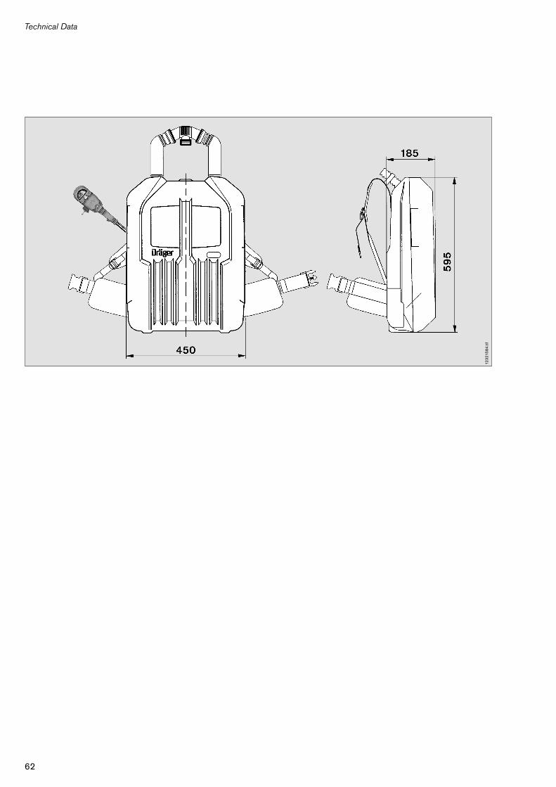
Dimensions (L x W x H) 595 x 450 x 185 mm
1) Even if the the recommended period of use is exceeded, the PSS BG 4 will operate correctly. Only the temperature of the inhaled air will increase.
62
Technical Data
123
215
84
.tif

63
Order List
Order List
Designation and description Order No.
PSS BG 4 AP R 34 507
Closed-circuit breathing apparatuswithout CO2 absorber,without full-face mask and without oxygen cylinder
PSS BG 4 CP R 34 508
Closed-circuit breathing apparatuswithout CO2 absorber,without full-face mask and without oxygen cylinder
Accessories required for operation
Full-face mask, either:
Panorama Nova - EPDM - PC - RP or R 53 306
Panorama Nova - SI - PC - RP R 53 316
Oxygen cylinders for PSS BG 4 AP:
2 L/3135 psi / steel /4h R 27 082
2 L/3000 psi / CFK /4h B 30 229
Oxygen cylinders for PSS BG 4 CP:
2 L/207 bar / CFK /4h B 30 230
2 L/200 bar / steel /4h B 03 390
CO2 absorber factory-packed cartridge R 34 360
Material for consumption
CO2 absorber factory-packed cartridge R 34 360
9.0 V battery for Sentinel 33 38 471
For CO2 absorber refill cartridge:
Empty refill cartridge, gray R 34 277
Empty refill cartridge, translucent R 34 367
Filter mats, set of 200 R 35 754
Filling station R 33 752
Dust sieve (2 pcs. necessary) R 34 239
DRÄGERSORB® 400
8 kg 67 37 965
18 kg 67 37 985
40 kg 67 55 001
Designation and description Order No.
Accessories for full-face mask
Neck strap R 51 772
Goggles R 51 548
Mask Box Wikov V R 51 019
Hairnet 40 56 017
BGComm
BGComm 40 56 764
Accessories consisting of: 40 56 201
Earspeaker Bracket
Bracket Screw
Earspeaker Knob
Earspeaker PTT Assembly 40 56 200
Interface Cable (varies to radio)
Additional Accessories
Universal test unit Rz 25 E 08 200
Test set BG 4/Tramix R 33 777
Ice receptacle R 33 999
Hose rinsing set R 27 092
Hose drying kit R 41 120
Reinforcing ring R 34 161
Molykote® 111 15 63 572
IR-Link II(set of IR-Link-cable and IR-Link-Software)
on request
Windows-Software on request
These Instructions for Use apply only to PSS BG 4 AP/CPwith Serial No.:Without the serial number entered by Dräger these Instructions for Use are for information only!
90 21 584 - GA 1114.114 enUS© Dräger Safety AG & Co. KGaA2nd edition - July 2004Subject to alteration
Manufactured byDräger Safety AG & Co. KGaARevalstraße 1D-23560 LübeckGermanyTel. +49 451 8 82 - 0Fax +49 451 8 82 - 20 80www.draeger-safety.com
Distributed byDräger Safety Inc.101 Technology DrivePittsburgh, PA 15275-1057USATel. +1 412 7 87- 83 83Fax +1 412 7 87- 22 07www.draeger-safety.com
ARWD–F001
Recommended