SPECIFICATIONS
PXI-40717½-Digit, ±1,000 V, Onboard 1.8 MS/s Isolated Digitizer, PXI DigitalMultimeter
These specifications apply to the PXI-4071.
ContentsDefinitions.................................................................................................................................2Conditions................................................................................................................................. 2DC Specifications..................................................................................................................... 2
DC System Speeds............................................................................................................ 3DC Accuracy Specifications............................................................................................. 3DC Functions General Specifications............................................................................... 9
AC Specifications................................................................................................................... 10AC System Speeds.......................................................................................................... 10AC Accuracy Specifications........................................................................................... 10AC Voltage General Specifications.................................................................................11AC Current General Specifications.................................................................................12
Frequency and Period..............................................................................................................13Temperature Accuracy Specifications (°C).............................................................................14Isolated Digitizer Specifications............................................................................................. 15
Acquisition System......................................................................................................... 16General Specifications............................................................................................................ 17
Trigger Characteristics.................................................................................................... 18Power Requirements....................................................................................................... 19Physical Characteristics.................................................................................................. 19
Environment............................................................................................................................19Operating Environment...................................................................................................19Storage Environment.......................................................................................................20Shock and Vibration........................................................................................................20
Compliance and Certifications................................................................................................20Safety.............................................................................................................................. 20Electromagnetic Compatibility....................................................................................... 20CE Compliance .............................................................................................................. 21Online Product Certification........................................................................................... 21Environmental Management........................................................................................... 21

DefinitionsWarranted specifications describe the performance of a model under stated operatingconditions and are covered by the model warranty.
Characteristics describe values that are relevant to the use of the model under stated operatingconditions but are not covered by the model warranty.• Typical specifications describe the expected performance met by a majority of the
models.• Nominal specifications describe parameters and attributes that may be useful in operation.
Specifications are Warranted unless otherwise noted.
ConditionsSpecifications are valid under the following conditions unless otherwise noted.• Calibration interval of 2 years• 1 hour of warm-up time
DC Specifications
Table 1. PXI-4071 DC Speeds, Nominal
Digits Bits Max Sampling Rate1 (Digitizer) Reading Rate2 (DMM)
7½ 26 N/A 7 S/s
6½ 22 100 S/s 100 S/s
5½ 18 5 kS/s 3 kS/s
4½ 15 20 kS/s 7 kS/s
3 10 1.8 MS/s N/A
1 Maximum sampling rates refer to waveform acquisition in digitizer mode.2 Auto Zero disabled, except 7½ digits, measured on a 10 V and 10 kΩ range.
2 | ni.com | PXI-4071 Specifications

Figure 1. DC Voltage Maximum Reading Rate, Nominal
7.5
7
Reading(s)
Dig
its
6.5
6
5.5
5
4.5
4
3.5
31 10 100 1 k 10 k 100 k 1 M 10 M
Reading Rate (DMM)Sampling Rate (Digitizer)
DC System SpeedsRange or function change 100/s
Auto Range time, DC V 5 ms
Auto Range time, DC I 10 ms
Auto Range time, resistance 50 ms
Trigger latency 2 μs
Maximum trigger rate 6 kHz
DC Accuracy SpecificationsNote All DC voltage accuracy specifications apply to 7½-digit resolution, AutoZero and ADC calibration enabled.
PXI-4071 Specifications | © National Instruments | 3
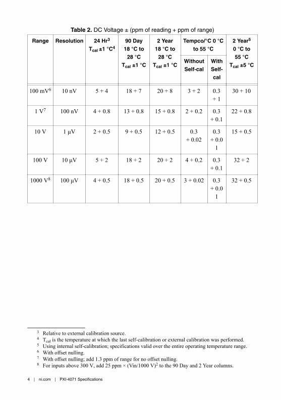
Table 2. DC Voltage ± (ppm of reading + ppm of range)
Range Resolution 24 Hr3
Tcal ±1 °C4
90 Day18 °C to
28 °CTcal ±1 °C
2 Year18 °C to
28 °CTcal ±1 °C
Tempco/°C 0 °Cto 55 °C
2 Year5
0 °C to55 °C
Tcal ±5 °CWithoutSelf-cal
WithSelf-cal
100 mV6 10 nV 5 + 4 18 + 7 20 + 8 3 + 2 0.3+ 1
30 + 10
1 V7 100 nV 4 + 0.8 13 + 0.8 15 + 0.8 2 + 0.2 0.3+ 0.1
22 + 0.8
10 V 1 μV 2 + 0.5 9 + 0.5 12 + 0.5 0.3+ 0.02
0.3+ 0.0
1
15 + 0.5
100 V 10 μV 5 + 2 18 + 2 20 + 2 4 + 0.2 0.3+ 0.1
32 + 2
1000 V8 100 μV 4 + 0.5 18 + 0.5 20 + 0.5 3 + 0.02 0.3+ 0.0
1
32 + 0.5
3 Relative to external calibration source.4 Tcal is the temperature at which the last self-calibration or external calibration was performed.5 Using internal self-calibration; specifications valid over the entire operating temperature range.6 With offset nulling.7 With offset nulling; add 1.3 ppm of range for no offset nulling.8 For inputs above 300 V, add 25 ppm × (Vin/1000 V)2 to the 90 Day and 2 Year columns.
4 | ni.com | PXI-4071 Specifications
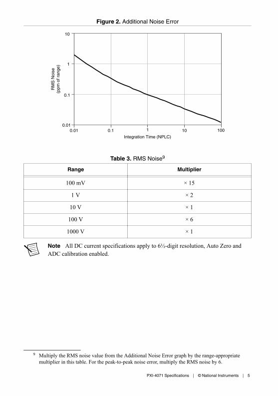
Figure 2. Additional Noise Error
10
Integration Time (NPLC)
RM
S N
oise
(p
pm o
f ran
ge) 1
0.1
0.010.01 0.1 1 10 100
Table 3. RMS Noise9
Range Multiplier
100 mV × 15
1 V × 2
10 V × 1
100 V × 6
1000 V × 1
Note All DC current specifications apply to 6½-digit resolution, Auto Zero andADC calibration enabled.
9 Multiply the RMS noise value from the Additional Noise Error graph by the range-appropriatemultiplier in this table. For the peak-to-peak noise error, multiply the RMS noise by 6.
PXI-4071 Specifications | © National Instruments | 5
Table 4. DC Current ± (ppm of reading + ppm of range)
Range Resolution BurdenVoltage
24 Hr10
Tcal ±1 °C90 Day18 °C to
28 °CTcal ±1 °C
2 Year18 °C to
28 °CTcal ±1 °C
Tempco11/°C0 °C to 55 °C
1 μA12 1 pA <55 mV 25 + 20 320 + 40 350 + 40 25 + 0.7
10 μA 12 10 pA <550 mV 25 + 2 320 + 15 350 + 15 25 + 0.7
100 μA 100 pA <60 mV 10 + 20 71 + 20 100 + 20 10 + 0.5
1 mA 1 nA <60 mV 4 + 20 80 + 20 100 + 20 4 + 0.5
10 mA 10 nA <60 mV 12 + 20 90 + 20 110 + 20 12 + 0.5
100 mA 100 nA <100 mV 9 + 20 140 + 20 165 + 20 15 + 0.5
1 A 1 μA <250 mV 15 + 20 240 + 20 290 + 20 11 + 0.5
3 A13 1 μA <700 mV 15 + 30 390 + 30 440 + 30 11 + 0.5
Table 5. Additional Noise Errors for Current
Resolution Additional Noise Error
5½ digits 10 ppm of range
5 digits 30 ppm of range
4½ digits 100 ppm of range
Note All resistance specifications apply to 7½-digit resolution, Auto Zero andADC calibration enabled.
10 Relative to external calibration source.11 Tempco is the temperature coefficient.12 90-day and 2-year specifications are typical.13 Above 2 A, add 300 ppm of reading to 90-day and 2-year specifications.
6 | ni.com | PXI-4071 Specifications

Table 6. Resistance (4-Wire and 2-Wire14) ± (ppm of reading + ppm of range)
Range15 TestCurrent16
MaxTest
Voltage
24 Hr17
Tcal 18±1 °C
90 Day18 °C to
28 °CTcal ±1 °C
2 Year18 °C to
28 °CTcal ±1 °C
Tempco19/°C0 °C to 55 °C
2 Year20
0 °C to55 °C
Tcal ±5 °CWithoutSelf-cal
WithSelf-cal
100 Ω21 1 mA 100 mV 8 + 2.5 31 + 4 56 + 4 6 + 0.12 0.8+ 0.1
2
60 + 5
1 kΩ21 1 mA 1 V 5 + 0.5 26 + 0.5 48 + 0.5 5 + 0.05 0.8+ 0.0
5
55 + 1
10 kΩ21 100 μA 1 V 5 + 0.5 26 + 0.5 48 + 0.5 5 + 0.05 0.8+ 0.0
5
55 + 1
100 kΩ22 10 μA 1 V 5 + 1 28 + 1 50 + 1 5 + 0.2 0.8+ 0.1
56 + 6
1 MΩ 10 μA 10 V 5 + 1 30 + 1 52 + 1 5 + 0.05 3+ 0.0
5
58 + 1
10 MΩ 1 μA 10 V 60 + 5 70 + 10 90 + 10 20 + 1 20+ 1
400 + 10
30 MΩ23 1 μA||10 MΩ
10 V 180 + 20 240 + 30 360 + 60 60 + 20 60+ 20
—
14 Perform offset nulling or add 200 mΩ to reading.15 For ranges ≥1 MΩ and relative humidity >80%, add 100 ppm/MΩ.16 -10% to 0% tolerance.17 Relative to external calibration source.18 Tcal is the temperature at which the last self-calibration or external calibration was performed.19 Tempco is the temperature coefficient.20 Using internal self-calibration; specifications valid over the entire operating temperature range.21 With offset compensated ohms enabled. For ADC calibration disabled, add 4 ppm of 100 Ω range
and 0.4 ppm of 1 kΩ and 10 kΩ range to the 90 Day and 2 Year columns.22 Perform offset nulling or add 1 ppm of range to the 24 Hr column and add 7 ppm of range to
90 Day and 2 Year columns.23 Applies to 100 MΩ range up to 30 MΩ. 2-wire resistance measurement only. Use tempco outside
18 °C to 28 °C.
PXI-4071 Specifications | © National Instruments | 7

Table 6. Resistance (4-Wire and 2-Wire14) ± (ppm of reading + ppm of range) (Continued)
Range15 TestCurrent16
MaxTest
Voltage
24 Hr17
Tcal 18±1 °C
90 Day18 °C to
28 °CTcal ±1 °C
2 Year18 °C to
28 °CTcal ±1 °C
Tempco19/°C0 °C to 55 °C
2 Year20
0 °C to55 °C
Tcal ±5 °CWithoutSelf-cal
WithSelf-cal
100 MΩ24 1 μA||10 MΩ
10 V 500 + 6 5500 + 10 6000 + 20 250 + 6 250+ 6
—
5 GΩ2425 1 μA||10 MΩ
10 V 1% + 0.2% 5%+ 0.2%
5%+ 0.2%
2500+ 0.2%
2500+ 0.2
%
—
Figure 3. Additional Noise Error
10
Integration Time (NPLC)
RM
S N
oise
(p
pm o
f Ran
ge)
1
0.10.01 0.1 1 10 100
14 Perform offset nulling or add 200 mΩ to reading.15 For ranges ≥1 MΩ and relative humidity >80%, add 100 ppm/MΩ.16 -10% to 0% tolerance.17 Relative to external calibration source.18 Tcal is the temperature at which the last self-calibration or external calibration was performed.19 Tempco is the temperature coefficient.20 Using internal self-calibration; specifications valid over the entire operating temperature range.24 2-wire resistance measurement only. Use tempco outside 18 °C to 28 °C.25 Typical specification.
8 | ni.com | PXI-4071 Specifications

Table 7. RMS Noise26
Range Multiplier
100 Ω × 8
1 kΩ × 1
10 kΩ × 1
100 kΩ × 2
1 MΩ × 3.5
10 MΩ × 5
100 MΩ × 55
5 GΩ × 2500
Note All diode specifications apply to 6½-digit resolution, Auto Zero and ADCcalibration enabled.
Table 8. Diode Test
Range Resolution Test Current27 Accuracy
10 V 10 μV 1 μA, 10 μA, 100 μA, 1 mA28 Add 20 ppm of reading to 10 VDCvoltage specifications.
DC Functions General SpecificationsEffective CMRR (1 kΩ resistance in LOlead)
>140 dB (DC), 100 ms aperture; >170 dB( >46 Hz) with high-order DC noise rejection,100 ms aperture
Maximum 4-wire lead resistance Use the lesser of 10% of range or 1 kΩ
Overrange 105% of range except 1000 V and 3 A range
DC voltage input bias current <30 pA at 23 °C, typical
Input Impedance >10 GΩ or 10 MΩ (100 mV, 1 V, and 10 Vranges only) in parallel with 90 pF, nominal
26 Multiply the RMS noise value from the Additional Noise Error graph by the range-appropriatemultiplier in the RMS Noise table. For the peak-to-peak noise error, multiply the RMS noise by 6.
27 -10% to 0% tolerance.28 Up to 4.0 V measurement for 1 mA test current.
PXI-4071 Specifications | © National Instruments | 9

Table 9. Normal-Mode Rejection Ratio (NMRR)
Readings/s NMRR Conditions
10 >100 dB29 All noise sources >46 Hz
50 (60) >60 dB30 50 (60) Hz ±0.1%
AC SpecificationsNote All AC speed specifications apply with Auto Zero disabled.
Table 10. PXI-4071 AC Bandwidth
Digits Reading Rate Bandwidth
6½ 0.25 S/s 1 Hz to 300 kHz
6½ 2.5 S/s 10 Hz to 300 kHz
6½ 25 S/s 100 Hz to 300 kHz
6½ 100.0 S/s 400 Hz to 300 kHz
5½ 1.0 kS/s 20 kHz to 300 kHz
AC System SpeedsRange or function change 10/s
Auto Range time, AC V and AC I 250 ms
Trigger latency 2 μs
Maximum trigger rate 1 kHz
AC Accuracy SpecificationsNote All AC accuracy specifications apply to 6½ digit resolution, signalamplitudes greater than 1% of range, and Auto Zero enabled.
29 With high-order DC noise rejection; 100 ms aperture.30 With normal DC noise rejection; 20 ms (16.67 ms) aperture.
10 | ni.com | PXI-4071 Specifications
Table 11. AC Voltage31 2 Year ± (% of reading + % of range), 18 °C to 28 °C
Range(RMS)
PeakVoltage
Resolution 1 Hz to40 Hz32
>40 Hzto
20 kHz
>20 kHzto 50 kHz
>50 kHzto
100 kHz
>100 kHzto 300 kHz
50 mV33 ±105 mV 100 nV 0.1+ 0.02
0.05+ 0.02
0.07+ 0.02
0.3 + 0.02 0.7 + 0.15
500 mV ±1.05 V 1 μV 0.1+ 0.005
0.05+ 0.005
0.06+ 0.01
0.2 + 0.01 0.7 + 0.15
5 V ±10.5 V 10 μV
50 V ±105 V 100 μV 0.1+ 0.005
0.06+ 0.01
0.12+ 0.05
0.6 + 0.05 3 + 0.15
700 V ±1000 V 1 mV
Table 12. AC Voltage Tempco/°C (0 °C to 55 °C)
Range (RMS) 1 Hz to40 Hz
>40 Hz to20 kHz
>20 kHz to50 kHz
>50 kHz to100 kHz
>100 kHz to300 kHz
50 mV500 mV
5 V
0.001+ 0.0002
0.001+ 0.0002
0.001 + 0.001 0.001 + 0.001 0.01 + 0.01
50 mV700 mV
0.001+ 0.0002
0.003+ 0.0002
0.012 + 0.001 0.045 + 0.001 0.1 + 0.01
AC Voltage General SpecificationsInput impedance 10 MΩ in parallel with 90 pF, nominal
Input coupling AC or DC coupling
Overrange 105% of range except 700 V
Maximum Volt-Hertz product >8 × 10⁷ V-Hz
Maximum DC voltage component 400 V
31 After self-calibration. Measurement aperture greater than 4/fL, where fL is the lowest frequencycomponent of the signal being measured.
32 Specification applies for DC coupling.33 Applies to signals >1 mVrms.
PXI-4071 Specifications | © National Instruments | 11

CMRR
1 kΩ resistance in LO lead >70 dB (DC to 60 Hz)
Over full bandwidth (without 1 kΩresistance in LO lead)
Refer to the CMRR Over Full Bandwidthgraph, typical.
Figure 4. CMRR Over Full Bandwidth, Typical
Frequency (kHz)
CM
RR
(dB
)
140
120
100
80
60
40
20
0.01 0.1 1.0 10 100 3000
Ranges >50 Vrms
Ranges <5 Vrms
AC Current General Specifications
Table 13. AC Current34 2 Year ± (% of reading + % of range), 18 °C to 28 °C
Range(RMS)
PeakCurrent
Resolution BurdenVoltage(RMS at1 kHz),Typical
1 Hzto
5 kHz
5 kHz to10 kHz35
10 kHz to20 kHz35
Tempco/°C(0 °C to55 °C)
100 μA36 ±200 μA 100 pA <60 mV 0.03+ 0.02
— — 0.002+ 0.0002
1 mA ±2 mA 1 nA <60 mV 0.03+ 0.02
0.06+ 0.02
0.08+ 0.02
0.001+ 0.0001
34 Measurement aperture greater than 4/fL, where fL is the lowest frequency component of the signalbeing measured.
35 Specification is typical above 5 kHz.36 Applies to signals >9 μArms and ≤1 kHz.
12 | ni.com | PXI-4071 Specifications
Table 13. AC Current34 2 Year ± (% of reading + % of range), 18 °C to28 °C (Continued)
Range(RMS)
PeakCurrent
Resolution BurdenVoltage(RMS at1 kHz),Typical
1 Hzto
5 kHz
5 kHz to10 kHz35
10 kHz to20 kHz35
Tempco/°C(0 °C to55 °C)
10 mA ±20 mA 10 nA <60 mV 0.03+ 0.02
0.06+ 0.02
0.08+ 0.02
0.002+ 0.0002
100 mA ±200 mA 100 nA <100 mV 0.03+ 0.02
0.06+ 0.02
0.15+ 0.02
0.001+ 0.0002
1 A ±2 A 10 μA <250 mV 0.1+ 0.02
0.24+ 0.02
0.8+ 0.02
0.002+ 0.0002
3 A ±4.2 A37 10 μA <700 mV 0.1+ 0.02
0.24+ 0.02
0.8+ 0.02
0.002+ 0.0001
Note No degradation in accuracy occurs due to crest factor for signals up to therated peak voltage/current or bandwidth. For high crest factor signals, increaserange. For example, for a 500 mVrms signal with a crest factor between 2 and 20,use the 5 V range.
Overrange 105% of range except 3 A range
Frequency and Period
Table 14. PXI-4071 Frequency and Period38
Input Range Frequency Range Period Range Resolution 2-Year Accuracy39
0 °C to 55 °C± % of reading
50 mV to 700 V 1 Hz to 500 kHz 1 s to 2 μs 6½ digits 0.01
34 Measurement aperture greater than 4/fL, where fL is the lowest frequency component of the signalbeing measured.
35 Specification is typical above 5 kHz.37 Sine wave only.38 2 second gate time; input signal must be >10% of AC voltage input range.39 0.00025% of reading, typical.
PXI-4071 Specifications | © National Instruments | 13
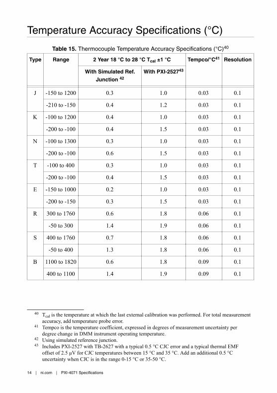
Temperature Accuracy Specifications (°C)
Table 15. Thermocouple Temperature Accuracy Specifications (°C)40
Type Range 2 Year 18 °C to 28 °C Tcal ±1 °C Tempco/°C41 Resolution
With Simulated Ref.Junction 42
With PXI-252743
J -150 to 1200 0.3 1.0 0.03 0.1
-210 to -150 0.4 1.2 0.03 0.1
K -100 to 1200 0.4 1.0 0.03 0.1
-200 to -100 0.4 1.5 0.03 0.1
N -100 to 1300 0.3 1.0 0.03 0.1
-200 to -100 0.6 1.5 0.03 0.1
T -100 to 400 0.3 1.0 0.03 0.1
-200 to -100 0.4 1.5 0.03 0.1
E -150 to 1000 0.2 1.0 0.03 0.1
-200 to -150 0.3 1.5 0.03 0.1
R 300 to 1760 0.6 1.8 0.06 0.1
-50 to 300 1.4 1.9 0.06 0.1
S 400 to 1760 0.7 1.8 0.06 0.1
-50 to 400 1.3 1.8 0.06 0.1
B 1100 to 1820 0.6 1.8 0.09 0.1
400 to 1100 1.4 1.9 0.09 0.1
40 Tcal is the temperature at which the last external calibration was performed. For total measurementaccuracy, add temperature probe error.
41 Tempco is the temperature coefficient, expressed in degrees of measurement uncertainty perdegree change in DMM instrument operating temperature.
42 Using simulated reference junction.43 Includes PXI-2527 with TB-2627 with a typical 0.5 °C CJC error and a typical thermal EMF
offset of 2.5 μV for CJC temperatures between 15 °C and 35 °C. Add an additional 0.5 °Cuncertainty when CJC is in the range 0-15 °C or 35-50 °C.
14 | ni.com | PXI-4071 Specifications
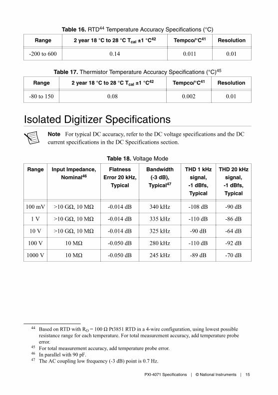
Table 16. RTD44 Temperature Accuracy Specifications (°C)
Range 2 year 18 °C to 28 °C Tcal ±1 °C42 Tempco/°C41 Resolution
-200 to 600 0.14 0.011 0.01
Table 17. Thermistor Temperature Accuracy Specifications (°C)45
Range 2 year 18 °C to 28 °C Tcal ±1 °C42 Tempco/°C41 Resolution
-80 to 150 0.08 0.002 0.01
Isolated Digitizer SpecificationsNote For typical DC accuracy, refer to the DC voltage specifications and the DCcurrent specifications in the DC Specifications section.
Table 18. Voltage Mode
Range Input Impedance,Nominal46
FlatnessError 20 kHz,
Typical
Bandwidth(-3 dB),
Typical47
THD 1 kHzsignal,-1 dBfs,Typical
THD 20 kHzsignal,-1 dBfs,Typical
100 mV >10 GΩ, 10 MΩ -0.014 dB 340 kHz -108 dB -90 dB
1 V >10 GΩ, 10 MΩ -0.014 dB 335 kHz -110 dB -86 dB
10 V >10 GΩ, 10 MΩ -0.014 dB 325 kHz -90 dB -64 dB
100 V 10 MΩ -0.050 dB 280 kHz -110 dB -92 dB
1000 V 10 MΩ -0.050 dB 245 kHz -89 dB -70 dB
44 Based on RTD with RO = 100 Ω Pt3851 RTD in a 4-wire configuration, using lowest possibleresistance range for each temperature. For total measurement accuracy, add temperature probeerror.
45 For total measurement accuracy, add temperature probe error.46 In parallel with 90 pF.47 The AC coupling low frequency (-3 dB) point is 0.7 Hz.
PXI-4071 Specifications | © National Instruments | 15

Table 19. Current Mode
Range Burden Voltage, Typical Flatness Error 20 kHz,Typical
Bandwidth (-3 dB), Typical
100 μA <60 mV ±0.42 dB 42 kHz
1 mA <60 mV ±0.01 dB 450 kHz
10 mA <60 mV ±0.01 dB 450 kHz
100 mA <100 mV ±0.01 dB 450 kHz
1 A <250 mV ±0.01 dB 450 kHz
3 A <700 mV ±0.01 dB 450 kHz
Acquisition SystemSampling rate and record duration
Available sampling rates � = 1.8��/�� , where y = 1, 2, 3,...1.8 × 105
Minimum record duration 8.89 μs
Maximum record duration 149 s
Record duration n/r, where n = number of samples,r = sampling rate
Variable resolution 10-23 bits; refer to Digitizer MaximumSampling Rate graph
Available functions Voltage and current
Voltage ranges ±100 mV to ±1000 V (DC or AC coupled)
Current ranges ±100 μA to ±3 A
Timebase accuracy 25 ppm
Input trigger
Latency48 3.6 μs
Jitter <600 ns
Note Refer to Trigger Specifications for additional input trigger specifications.
48 The latency specification value actually reflects negative latency due to sampling before the trigger.Can be reduced to near zero (with the jitter specification) or made positive in software by adding atrigger delay.
16 | ni.com | PXI-4071 Specifications

Figure 5. Digitizer Maximum Sampling Rate, Nominal
24
Samples(s)
Bits
810 100 1 k 10 k 100 k 1 M 10 M
10
12
14
16
18
20
22
General SpecificationsWarm-up 1 hour to rated accuracy
Self-calibration Calibrates the FlexDMM relative to high-precision internal voltage and resistancestandards. No external calibration equipmentrequired.
External calibration interval 2 year recommended
Measurement category I49 (up to 1000 VDC or ACrms), II (up to500 VDC or ACrms)
Caution Do not use this device for connection to signals or for measurementswithin Measurement Categories III or IV.
Input protection
Resistance
2-wire Up to 1000 VDC
4-wire Up to 500 VDC
49 Measurement Categories CAT I and CAT O (Other) are equivalent. These test and measurementcircuits are not intended for direct connection to the MAINs building installations of MeasurementCategories CAT II, III, or CAT IV.
PXI-4071 Specifications | © National Instruments | 17
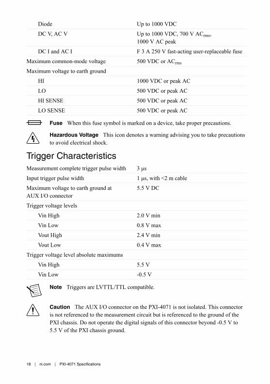
Diode Up to 1000 VDC
DC V, AC V Up to 1000 VDC, 700 V ACrms,1000 V AC peak
DC I and AC I F 3 A 250 V fast-acting user-replaceable fuse
Maximum common-mode voltage 500 VDC or ACrms
Maximum voltage to earth ground
HI 1000 VDC or peak AC
LO 500 VDC or peak AC
HI SENSE 500 VDC or peak AC
LO SENSE 500 VDC or peak AC
Fuse When this fuse symbol is marked on a device, take proper precautions.
Hazardous Voltage This icon denotes a warning advising you to take precautionsto avoid electrical shock.
Trigger CharacteristicsMeasurement complete trigger pulse width 3 μs
Input trigger pulse width 1 μs, with <2 m cable
Maximum voltage to earth ground atAUX I/O connector
5.5 V DC
Trigger voltage levels
Vin High 2.0 V min
Vin Low 0.8 V max
Vout High 2.4 V min
Vout Low 0.4 V max
Trigger voltage level absolute maximums
Vin High 5.5 V
Vin Low -0.5 V
Note Triggers are LVTTL/TTL compatible.
Caution The AUX I/O connector on the PXI-4071 is not isolated. This connectoris not referenced to the measurement circuit but is referenced to the ground of thePXI chassis. Do not operate the digital signals of this connector beyond -0.5 V to5.5 V of the PXI chassis ground.
18 | ni.com | PXI-4071 Specifications

Power RequirementsCaution Do not operate the PXI-4071 in a manner not specified in this document.Product misuse can result in a hazard. You can compromise the safety protectionbuilt into the product if the product is damaged in any way. If the product isdamaged, return it to NI for repair.
Power consumption <8 W from PXI backplane
Table 20. PXI-4071 Power Requirements, Typical
Rail Voltage Current Consumption Power Consumption
12 V 500 mA 6.00 W
5 V 30 mA 0.15 W
3.3 V 230 mA 0.76 W
-12 V 0 mA 0.00 W
Physical CharacteristicsDimensions 3U, one-slot, PXI/cPCI module
2.0 cm × 13.0 cm × 21.6 cm (0.8 in. × 5.1 in. ×8.5 in.)
Weight 314 g (11 oz)
Note If you need to clean the device, wipe it with a dry towel.
EnvironmentMaximum altitude 2,000 m (at 25 °C ambient temperature)
Pollution Degree 2
Indoor use only.
Operating EnvironmentAmbient temperature range 0 °C to 55 °C (Tested in accordance with
IEC 60068-2-1 and IEC 60068-2-2.)
Relative humidity range Up to 95% at 40 °C
PXI-4071 Specifications | © National Instruments | 19

Storage EnvironmentAmbient temperature range -40 °C to 70 °C (Tested in accordance
with IEC 60068-2-1 and IEC 60068-2-2.)
Relative humidity range 5% to 95%, noncondensing (Tested inaccordance with IEC 60068-2-56.)
Shock and VibrationOperational shock 30 g peak, half-sine, 11 ms pulse (Tested in
accordance with IEC 60068-2-27. Test profiledeveloped in accordance withMIL-PRF-28800F.)
Random vibration
Operating 5 Hz to 500 Hz, 0.3 grms (Tested in accordancewith IEC 60068-2-64.)
Nonoperating 5 Hz to 500 Hz, 2.4 grms (Tested in accordancewith IEC 60068-2-64. Test profile exceeds therequirements of MIL-PRF-28800F, Class 3.)
Compliance and Certifications
SafetyThis product is designed to meet the requirements of the following electrical equipment safetystandards for measurement, control, and laboratory use:• IEC 61010-1, EN 61010-1• UL 61010-1, CSA C22.2 No. 61010-1
Note For UL and other safety certifications, refer to the product label or the OnlineProduct Certification section.
Electromagnetic CompatibilityThis product meets the requirements of the following EMC standards for electrical equipmentfor measurement, control, and laboratory use:• EN 61326-1 (IEC 61326-1): Class A emissions; Basic immunity• EN 55011 (CISPR 11): Group 1, Class A emissions• EN 55022 (CISPR 22): Class A emissions• EN 55024 (CISPR 24): Immunity• AS/NZS CISPR 11: Group 1, Class A emissions• AS/NZS CISPR 22: Class A emissions
20 | ni.com | PXI-4071 Specifications

• FCC 47 CFR Part 15B: Class A emissions• ICES-001: Class A emissions
Caution To ensure the specified EMC performance, operate this product accordingto the documentation.
Note In the United States (per FCC 47 CFR), Class A equipment is intended foruse in commercial, light-industrial, and heavy-industrial locations. In Europe,Canada, Australia, and New Zealand (per CISPR 11), Class A equipment is intendedfor use only in heavy-industrial locations.
Note Group 1 equipment (per CISPR 11) is any industrial, scientific, or medicalequipment that does not intentionally generate radio frequency energy for thetreatment of material or inspection/analysis purposes.
Note For EMC declarations, certifications, and additional information, refer to the Online Product Certification section.
CE Compliance This product meets the essential requirements of applicable European Directives, as follows:• 2014/35/EU; Low-Voltage Directive (safety)• 2014/30/EU; Electromagnetic Compatibility Directive (EMC)
Online Product CertificationRefer to the product Declaration of Conformity (DoC) for additional regulatory complianceinformation. To obtain product certifications and the DoC for this product, visit ni.com/certification, search by model number or product line, and click the appropriate link in theCertification column.
Environmental ManagementNI is committed to designing and manufacturing products in an environmentally responsiblemanner. NI recognizes that eliminating certain hazardous substances from our products isbeneficial to the environment and to NI customers.
For additional environmental information, refer to the Minimize Our Environmental Impactweb page at ni.com/environment. This page contains the environmental regulations anddirectives with which NI complies, as well as other environmental information not included inthis document.
Waste Electrical and Electronic Equipment (WEEE)EU Customers At the end of the product life cycle, all NI products must bedisposed of according to local laws and regulations. For more information abouthow to recycle NI products in your region, visit ni.com/environment/weee.
PXI-4071 Specifications | © National Instruments | 21

电子信息产品污染控制管理办法(中国 RoHS)中国客户 National Instruments 符合中国电子信息产品中限制使用某些有害物
质指令(RoHS)。关于 National Instruments 中国 RoHS 合规性信息,请登录
ni.com/environment/rohs_china。(For information about China RoHScompliance, go to ni.com/environment/rohs_china.)
Information is subject to change without notice. Refer to the NI Trademarks and Logo Guidelines at ni.com/trademarks forinformation on NI trademarks. Other product and company names mentioned herein are trademarks or trade names of theirrespective companies. For patents covering NI products/technology, refer to the appropriate location: Help»Patents in yoursoftware, the patents.txt file on your media, or the National Instruments Patent Notice at ni.com/patents. You can findinformation about end-user license agreements (EULAs) and third-party legal notices in the readme file for your NI product. Referto the Export Compliance Information at ni.com/legal/export-compliance for the NI global trade compliance policy and howto obtain relevant HTS codes, ECCNs, and other import/export data. NI MAKES NO EXPRESS OR IMPLIED WARRANTIES ASTO THE ACCURACY OF THE INFORMATION CONTAINED HEREIN AND SHALL NOT BE LIABLE FOR ANY ERRORS. U.S.Government Customers: The data contained in this manual was developed at private expense and is subject to the applicablelimited rights and restricted data rights as set forth in FAR 52.227-14, DFAR 252.227-7014, and DFAR 252.227-7015.
© 2005—2017 National Instruments. All rights reserved.
371371M-01 Jan17
Recommended