ON A
THE S
NATIAUTOMA
SOCIALIS
QCVN
ONAL TEATIC AND
ST REPU
60: 201
ECHNICAD REMO
HANOI 2
BLIC OF
13/BGTV
AL REGUTE CONT
2013
F VIETNA
VT
ULATIONTROL SY
AM
N YSTEMS

Preamble
National Technical Regulation on Automatic and Remote Control Systems QCVN 60: 2013/BGTVT is compiled by Vietnam Register, verified by the Ministry of Science and Technology, promulgated by the Minister of Transport under Circular No. 06/2013/TT-BGTVT dated 2 May 2013.
QCVN 60: 2013/BGTVT is complied on the basis of National Standard "Rules for Automatic and Remote Control Systems" TCVN 6277: 2003.

QCVN 60: 2013/BGTVT
5
NATIONAL TECHNICAL REGULATION ON AUTOMATIC AND REMOTE CONTROL SYSTEMS
CONTENTS
Page
I GENERAL REGULATIONS ....................................................................................... 7
1.1 Scope and application ...................................................................................... 7
1.2 References and terminologies ........................................................................... 7
II TECHNICAL REGULATIONS .................................................................................... 11
Chapter 1 General ........................................................................................................ 11
1.1 General ............................................................................................................. 11
1.2 System Design .................................................................................................. 11
1.3 Prevention of flooding and fire safety measures ............................................... 12
Chapter 2 Surveys of Automatic and Remote Control Systems ........................... 14
2.1 General ............................................................................................................. 14
2.2 Registration Surveys ......................................................................................... 16
2.3 Registration maintenance surveys ..................................................................... 19
Chapter 3 Centralized Monitoring and Control Systems for Machinery ............... 22
3.1 General ............................................................................................................. 22
3.2 Centralized Monitoring and Control Systems for Machinery ............................. 22
3.3 Additional requirements for safety measures .................................................... 23
Chapter 4 Monitoring and Control Systems for Periodically Unattended Machinery Spaces .................................................................................... 37
4.1 General ............................................................................................................. 37
4.2 Monitoring and control systems for periodically unattended machinery spaces ............................................................................................................... 37
4.3 Safety measures, etc. ........................................................................................ 39
Chapter 5 Specific Automation Equipment ............................................................. 41
5.1 General ............................................................................................................. 41
5.2 Specific Automation Equipment ......................................................................... 41
5.3 Standards for specific automation equipment .................................................... 41
QCVN 60: 2013/BGTVT
6
III REGULATIONS ON MANAGEMENT ........................................................................ 47
1.1 General .............................................................................................................. 47
1.2 Regulations on technical supervisions ............................................................... 47
1.3 Certification ........................................................................................................ 47
IV RESPONSIBILITIES OF ORGANIZATIONS, INDIVIDUALS .................................... 48
1.1 Responsibilities of ship owners and operators, agency of design, manufacturing, converting, renovating and repairing the systems..................... 48
1.2 Responsibilities of Vietnam Register .................................................................. 48
1.3 Responsibilities of the Ministry of Transport ....................................................... 49
V IMPLEMENTATION .................................................................................................... 50
QCVN 60: 2013/BGTVT
7
NATIONAL TECHNICAL REGULATION ON AUTOMATIC
AND REMOTE CONTROL SYSTEMS
I GENERAL REGULATIONS
1.1 Scope and application
1.1.1 Scope
1 This National Technical Regulations (hereinafter referred to as “Regulations”) apply to the survey and construction automatic and remote control systems of ships which are surveyed and classed by Vietnam Register.
2 The requirements given in Chapter 18 Part 3 Part 3 QCVN 21: 2010/BGTVT “National Technical Regulation on the Classification and Construction of Sea-going Steel Ships” are also to apply to any equipment and systems used for automatic and remote control systems in addition to those specified in this Regulation.
1.1.2 Application
This Regulation apply to organizations, individuals involving in automatic and remote control systems which fall under the application as specified in 1.1.1 above which are Vietnam Register (hereinafter referred to as the “VR”); ship owners; ship designers, ship yards; conversions; renovations; repairs and operation of the automatic and remote control systems.
1.2 References and terminologies
1.2.1 References
1 QCVN 21: 2010/BGTVT, National Technical Regulation - Rules for the classification and construction of sea-going steel ships promulgated in accordance with Circular 12/2010/TT-BGTVT dated 21 April 2010.
2 The Circular No.32/2011/TT-BGTVT: Circular regarding amendment and supplementation of a number of articles of the Regulation on registration of Vietnamese seagoing ships, promulgated together with Transport Minister’s Decision No. 51/2005/QĐ-BGTVT dated 12 October 2005.
1.1.2 Terminologies
The terms in the Rules, in addition to those defined in 18.1.2 Part 3 Section II QCVN 21: 2010/BGTVT, are defined as follows:
(1) Specific automation equipment, a general term for Class A specific automation equipment, Class B specific automation equipment, Class C specific automation equipment and Class D specific automation equipment is defined as follows:

QCVN 60: 2013/BGTVT
8
(a) Class A specific automation equipment
Remote-controlled fuel oil filling arrangements, remote-control mooring arrangements, automatic steering systems, remote-controlled handling systems for liquid cargo in bulk, remote-controlled ballasting/deballasting arrangements, power-operated opening/closing appliances and automatic main propulsion machinery recording devices.
(b) Class B specific automation equipment
Remote-controlled fuel oil filling arrangements, remote-controlled mooring arrangements, automatic steering systems, remote-controlled handling systems for liquid cargo in bulk, remote-controlled ballasting/deballasting arrangements, power-operated opening/closing appliances, monitoring devices of refrigeration containers, emergency towing rope winches, cargo hose handling winches, automatic main propulsion machinery recording devices and centralized machinery monitoring systems.
(c) Class C specific automation equipment
Remote-controlled fuel oil filling arrangements, independent remote-controlled mooring arrangements, automatic steering systems, remote-controlled handling systems for liquid cargo in bulk, remote-controlled ballasting/deballasting arrangements, power-operated opening/closing appliances, monitoring devices of refrigeration containers, emergency towing rope winches, cargo hose handling winches, automatic main propulsion machinery recording devices, centralized machinery monitoring systems, centralized machinery control systems, power-operated pilot ladder winding appliances and fixed deck washing arrangements.
(d) Class D specific automation equipment
Remote-controlled fuel oil filling arrangements, independent remote-controlled mooring arrangements, automatic steering systems, remote-controlled handling systems for liquid cargo in bulk, remote-controlled ballasting/deballasting arrangements, power-operated opening/closing appliances, monitoring devices of refrigeration containers, emergency towing rope winches, cargo hose handling winches, automatic main propulsion machinery recording devices, centralized machinery monitoring systems, centralized machinery control systems, power-operated pilot ladder winding appliances, fixed deck washing arrangements and bridge wing control devices.
(2) The term MC-ship means those ships which are to be registered as a ship in which the centralized monitoring and control systems for machinery in accordance with those requirements given in Chapter 3 Section II are installed.
(3) The term M0-ship means those ships which are to be registered as a ship in which the monitoring and control systems for periodically unattended machinery spaces in accordance with those requirements given in Chapter 4 Section II are installed.
QCVN 60: 2013/BGTVT
9
(4) The term M0.A-ship means those ships which are to be registered as a M0-ship in which the Class A specific automation equipment in accordance with those requirements given in 5.2.1 Section II is installed.
(5) The term M0.B-ship means those ships which are to be registered as a M0-ship in which the Class B specific automation equipment in accordance with those requirements given in 5.2.2 Section II is installed.
(6) The term M0.C-ship means those ships which are to be registered as a M0-ship in which the Class C specific automation equipment in accordance with those requirements given in 5.2.3 Section II is installed.
(7) The term M0.D-ship means those ships which are to be registered as a M0-ship in which the Class D specific automation equipment in accordance with those requirements given in 5.2.4 Section II is installed.
(8) Anniversary date means the day each year corresponding to the expiration date of classification certificates, excluding the expiration dates of classification certificates.
(9) Centralized monitoring and control systems for machinery mean those remote monitoring and control systems used for main propulsion machinery, boilers, generating sets and other auxiliary machinery which are arranged in a centralized manner.
(10) Centralized control stations means those rooms, other than the bridge, in which centralized monitoring and control systems for machinery are installed and from which main propulsion machinery is normally controlled.
(11) Centralized monitoring and control stations on bridges means ship wheelhouses in which centralized monitoring and control systems for machinery are installed and from which main propulsion machinery is normally controlled.
(12) Monitoring and control systems for periodically unattended machinery spaces mean those systems which operate machinery and equipment specified in the following (a) to (g) without watch-keeping personnel assigned specific duties of operation and surveillance during a predetermined period.
(a) Main propulsion machinery (propulsion generating sets in electric propulsion ships are excluded)
(b) Controllable pitch propellers
(c) Steam generating sets
(d) Electric generating sets (propulsion generating sets in electric propulsion ships are included)
(e) Auxiliary machinery associated with the machinery and equipment listed in (a) to (d)
(f) Fuel oil systems
QCVN 60: 2013/BGTVT
10
(g) Bilge systems
(13) Bridge means the area from which navigation and control of ships are exercised, including wheelhouses and bridge wings.
(14) Bridge wings mean those parts of the bridge on both sides of ship wheelhouses which extended to ship sides.
(15) Wheelhouses mean enclosed areas of the bridge.
QCVN 60: 2013/BGTVT
11
II TECHNICAL REGULATIONS
CHAPTER 1 GENERAL
1.1 General
1.1.1 Equivalency
Automatic and remote control systems which do not fully comply with the requirements of the Regulation may be accepted provided that they are deemed by VR to be equivalent to those specified in the Regulation
1.1.2 Modification of Requirements
In cases where considered appropriate, VR may modify parts of any requirements specified in the Regulation in consideration of the national requirements of the ship flag states, ship type and intended service areas of ships
1.1.3 Automatic and Remote Control Systems with Novel Design Features
In the case of automatic and remote control systems with novel design features, VR may impose appropriate requirements of the Rules to the extent that they are practically applicable with additional requirements made on design and test procedures other than those specified in the Regulation.
1.1.4 Manuals for setting points of alarms and safety devices
The documents, in which the setting points and their confirmation test methods of alarms and safety devices are recorded, are to be kept on board..
1.2 System Design
1.2.1 System Design
1 System design is to comply with the following requirements in addition to those specified in 18.2.1 Part 3 Section II QCVN 21: 2010/BGTVT.
(1) Control systems, alarm systems and safety systems are to be independent each other as far as practicable.
(2) Safety systems intended for those functions specified in 18.1.2(10)(c) Part 3 Section II QCVN 21: 2010/BGTVT are to be, in all cases, independent of the other systems.
(3) Means are to be provided for safety systems to investigate the cause of the action of any safety systems.
1.2.2 Alarm Systems

QCVN 60: 2013/BGTVT
12
1 Alarm systems are to comply with the following requirements in addition to those specified in 18.2.5 Part 3 Section II QCVN 21: 2010/BGTVT.
(1) Alarm systems are to be provided with self-monitoring properties.
(2) Alarm systems are to be capable of being tested during normal machinery operation.
(3) In cases where practicable, means are to be provided at convenient and accessible positions to test sensors without affecting the operation of any machinery.
(4) Visual and audible alarms are to be designed to keep detecting until being accepted even in the case of transient faults which may be subsequently self-corrected.
1.2.3 Computers and computerized systems
1 The construction of systems in which computers are used is to comply with the following requirements in addition to those specified in 18.2.7 Part 3 Section II QCVN 21: 2010/BGTVT.
(1) Control systems, alarm systems and safety systems are in general to be independent each other in accordance with the requirements given in 1.2.1, 18.2.4-1 and 18.2.6-1, Part 3 Section II QCVN 21: 2010/BGTVT. However, in cases where it is considered impracticable, they may be as deemed appropriate by VR.
(2) With respect to alarm systems, alternative alarm systems or a back-up means for computers are to be provided.
1.3 Prevention of flooding and fire safety measures
1.3.1 Prevention of Flooding
1 The capacities of bilge wells in spaces where main propulsion machinery, propulsion shafting systems, boilers, electric generating sets and auxiliary machinery essential for main propulsion of ships are installed and in any other spaces considered necessary by VR, are to be sufficient enough to accumulate the drainage under normal machinery operational conditions. Furthermore, high level alarm devices are to be provided at two or more positions in such wells so that any increase of bilge can be detected at normal angles of heel and trim, except for such spaces where VR accepts that there is no fear of flooding.
2 In cases where bilge pumps are capable of being started and stopped automatically, small bilge wells may be accepted with consideration given to the operating frequency of such pumps.
3 In cases where bilge pumps are capable of being started and stopped automatically, alarm devices are to be provided to indicate either one of the following conditions:
(1) In cases where the influx of bilge is greater than pump capacity.
(2) In cases where pumps are operating more frequently than expected.

QCVN 60: 2013/BGTVT
13
4 Control devices of any valves using sea inlets, discharge outlets located below summer load lines or bilge injection systems are to be located so as to allow adequate time for operation in cases where flooding of spaces happens under fully loaded conditions of ships, having regard to the time likely to be required in order to reach and operate such control devices.
1.3.2 Fire Safety Measures
Additional fire safety measures are to be arranged in accordance with those requirements given in 5.2.3, 7.4, 10.2.1-2, 10.5.3-1 and 10.5.5-2 Part 5 Section II QCVN 21: 2010/BGTVT.

QCVN 60: 2013/BGTVT
14
CHAPTER 2 SURVEYS OF AUTOMATIC AND REMOTE CONTROL SYSTEMS
2.1 General
2.1.1 Kinds of surveys
1 Automatic and remote control systems registered or intended to be registered are to be subjected to the following surveys:
(1) Surveys for registration of automatic and remote control systems (hereinafter referred to as "Registration Surveys")
(2) Surveys for maintaining registration of the automatic and remote control systems (hereinafter referred to as "Registration Maintenance Surveys"), which are:
(a) Special Surveys;
(b) Annual Surveys;
(c) Occasional Surveys.
2.1.2 Survey Intervals
1 Registration surveys are to be carried out at the time of application for registration.
2 Registration maintenance surveys are to be carried out at those times as prescribed in (1) to (3) below.
(1) Special surveys are to be carried out at those intervals specified in 1.1.3-1(3) Part 1B Section II QCVN 21: 2010/BGTVT.
(2) Annual surveys are to be carried out at those intervals specified in 1.1.3-1(1) Part 1B Section II QCVN 21: 2010/BGTVT.
(3) Occasional surveys: at a time falling on any of (a) to (c) mentioned below, independently of special surveys and annual surveys.
(a) In cases where any main parts of systems have been damaged, repaired or renewed.
(b) In cases where any systems are modified or altered.
(c) In cases where considered necessary by VR.
2.1.3 Special surveys and annual surveys carried out in advance, etc.
1 Surveys carried out in advance
The requirements for Special Surveys and Annual Surveys carried out in advance are to be in accordance with those provisions specified in 1.1.4 Part 1B Section II QCVN 21: 2010/BGTVT.
2 Postponement of special surveys

QCVN 60: 2013/BGTVT
15
The requirements for the postponement of Special Surveys are to be in accordance with those provisions specified in 1.1.5-1(1) or 1.1.5-1(2)1 Part 1B Section II QCVN 21: 2010/BGTVT.
2.1.4 Preparation for surveys and others
1 All such preparations required for surveys to be carried out as well as any preparations which may be required by Surveyors as necessary in accordance with the requirements given in the Regulation are to be made by survey applicants. Such preparations are to include provisions for easy and safe access, necessary facilities and necessary records for survey execution. Any inspection, measuring and test equipment, which Surveyors rely on to make decisions affecting classification are to be individually identified and calibrated to standards deemed appropriate by VR. However, Surveyors may accept simple measuring equipment (e.g. rulers, measuring tapes, weld gauges, micrometers) without individual identification or confirmation of calibration, provided that they are of standard commercial design, properly maintained and periodically compared with other similar equipment or test pieces. Surveyors may also accept equipment fitted on board ship and used in the examination of shipboard equipment (e.g. pressure, temperature or rpm gauges and meters) based either on calibration records or comparison of readings with multiple instruments.
2 Survey applicants are to arrange supervisors who are well conversant with those survey items intended for survey preparation in order to provide any necessary assistance to Surveyors according to their requests during surveys.
3 Surveys may be suspended in cases where:
(1) The necessary preparations have not been made;
(2) Any appropriate attendant mentioned in the -2 above is not present; or
(3) Surveyors consider that safety for survey execution is not ensured.
4 In cases where repairs are deemed necessary as a result of a survey, Surveyors will notify survey applicants of their recommendations. Upon notification, repairs are to be made to the satisfaction of the Surveyor.
2.1.5 Laid-up ships
1 Laid-up ships are not subject to registration maintenance surveys. However, occasional surveys may be carried out at the request of owners.
2 When laid-up ships are about to be re-entering service, the following surveys and surveys for specific matters which have been postponed due to being laid-up, if any, are to be carried out.
(1) If the due dates for registration maintenance surveys have not transpired while the ship was laid-up, then an equivalent to the annual surveys specified in 2.3.2 is to be carried out.
(2) If the due dates for registration maintenance surveys have transpired while the ship

QCVN 60: 2013/BGTVT
16
was laid-up, then these registration maintenance surveys are, in principle, to be carried out. However, in cases where special surveys and annual surveys are due, only the special surveys may be carried out.
2.2 Registration Surveys
2.2.1 Drawings and Data
1 In the case of automatic and remote control systems, three copies of the following drawings and data are to be submitted.
(1) Centralized monitoring and control systems for machinery or monitoring and control systems for periodically unattended machinery spaces:
(a) Drawings and data specified in 18.1.3 Part 3 Section II QCVN 21: 2010/BGTVT;
(b) Drawings and data relative to computers;
(c) Schedules of on-board tests and sea trials;
(2) Specific automation equipment:
(a) Drawings showing construction and layouts;
(b) Drawings and data relative to automatic and remote controls;
(c) Particulars.
(3) Drawings and data other than those above in cases where deemed necessary by VR.
2.2.2 Shop Tests
The devices, units, sensors and those systems composed of them which are used for centralized monitoring and control systems for machinery or monitoring and control systems for periodically unattended machinery spaces, in cases where considered necessary by VR, are to be subjected to those environmental tests and completion tests specified in 18.7.1 Part 3 Section II QCVN 21: 2010/BGTVT after being manufactured.
2.2.3 Approval of Use
Approval of use for those devices and equipment which have passed those environmental tests specified in 2.2.2 above is to be in accordance with those requirements specified in 18.7.2 Part 3 Section II QCVN 21: 2010/BGTVT.
2.2.4 Tests after Installation on Board
The devices and equipment controlled by automatic and remote control systems, in cases where deemed necessary by VR, are to be confirmed to operate so as not to endanger ship safety even in cases where control systems fail as well as in addition to those tests specified in 18.7.3 Part 3 Section II QCVN 21: 2010/BGTVT.
2.2.5 Sea Trials
QCVN 60: 2013/BGTVT
17
1 Centralized monitoring and control systems for machinery are to be subjected to the following tests:
(1) Main propulsion machinery and controllable pitch propellers
(a) Main propulsion machinery or controllable pitch propellers are to be subjected to starting tests, ahead-astern tests and running tests in their whole range of output, by means of remote control devices from centralized control stations or centralized monitoring and control stations on bridges.
(b) In addition to output increase and decrease tests, operation tests of the main propulsion machinery or the controllable pitch propellers using bridge control devices are to be carried out as deemed appropriate by VR.
(c) In cases where there are two or more control stations for main propulsion machinery or controllable pitch propellers, tests on the transfer of control are to be carried out during ahead and astern operations of such main propulsion machinery or controllable pitch propellers. In cases where the transfer of control of remote control devices of main propulsion machinery or controllable pitch propellers is carried out in accordance with 18.3.2-2(3)(b) Part 3 Section II QCVN 21: 2010/BGTVT, the above-mentioned tests are to be carried out during stopping conditions of main propulsion machinery.
(d) After completion of those tests on the transfer of control specified in (c) above, it is to be shown that main propulsion machinery or the controllable pitch propellers can be smoothly operated from their respective control stations.
(2) Boilers
(a) With respect to main boilers, it is to be confirmed that feed water control devices, combustion control devices and so on can operate stably in response to any load variations of main boilers, and such main boilers can stably supply steam to main propulsion machinery, the electric generating sets and any auxiliary machinery essential for main propulsion of ships without any local manual operations.
(b) With respect to essential auxiliary boilers, it is to be confirmed that they can supply steam stably to any auxiliary machinery essential for main propulsion of ships without any manual operations.
(c) In cases where exhaust gas economizers are used as sources of steam supplies to turbines for driving generators and steam is supplied from boilers automatically in cases where low power conditions of main propulsion machinery, operation tests of automatic control devices for such systems are to be carried out.
(3) Electric generating sets
In cases where generators driven by main propulsion machinery are installed, systems of automatic or remote control of electric generating sets are to be subjected to operation tests.
QCVN 60: 2013/BGTVT
18
2 Monitoring and control systems for periodically unattended machinery spaces are to be subjected to the following tests in addition to those tests specified in -1 above.
(1) In substitution of those tests specified in -1(1)(a) and (b) above, main propulsion machinery or controllable pitch propellers are to be confirmed to be safely and surely operated in all service ranges of outputs including starting and ahead-astern conditions, by means of centralized monitoring and control systems for machinery or bridge control devices.
(2) The electric generating sets are to be subjected to the following tests while the ship is navigating at normal sea going speed.
(a) In case where only one electric generating set is normally used, when stopping the main source of electrical power by tripping the circuit breaker, it is to be confirmed that automatic starting of the standby generator, automatic making of the air circuit breaker and sequential starting of important auxiliaries are performed.
(b) In case where two electric generating sets are normally used, when tripping the circuit breaker for one set, it is to be confirmed that preference tripping of non-important loads is performed, and propulsion and steering of the ship are maintained.
(3) Auxiliary machinery (excluding any auxiliary machinery for specific use and other auxiliary machinery) is to be subjected to the following tests while controlling main propulsion machinery or controllable pitch propellers from the bridge.
(a) Automatic starting tests of those standby pumps specified in 3.3.2-1(3), 3.3.2-2(3)(a), 3.3.2-3(3), 3.3.2-4(1), 3.3.3-2, 3.3.5-1 and 18.2.2-2(3) Part 3 Section II QCVN 21: 2010/BGTVT, and automatic changeover tests for those circulating pumps specified in 3.3.2-2(3)(b).
(b) Tests to confirm that, while main propulsion machinery is operating under normal continuous cruise output, exclusive air reservoirs for control use, if fitted, are capable of supplying air for at least five minutes after operation of low pressure alarms for control air on the condition that the automatic starting functions of control air compressors is stopped.
(4) In cases where exhaust gas economizers are used as sources of steam supply to turbines for driving generators, the following are to be confirmed:
(a) While any main propulsion machinery is operating under normal continuous cruise outputs, additional heating for boilers and automatic starting for diesel engine driven generating sets are to be performed in cases where any handles of main propulsion machinery are rapidly put back into stop positions.
(b) When the main propulsion machinery is operated from a stopping position to a normal continuous cruise output expeditiously, no critical condition occurs to water separator drums, piping, steam turbines and so on.
QCVN 60: 2013/BGTVT
19
(5) After completion of tests specified in (1) to (4) above, it is to be confirmed that the machinery can be safely and surely monitored and controlled under an unattended machinery operating condition as far similar to the normal sea going condition as practicable. In this case, except where the operation mode is changed over, the running condition of the machinery is not to be adjusted by means of manual operation from any control station other than that on navigation bridge (including the centralized monitoring and control station on bridge).
2.3 Registration maintenance surveys
2.3.1 Special surveys
1 During Special Surveys of centralized monitoring and control systems for machinery, the following devices or systems are to be functionally tested and placed in order.
(1) Main propulsion machinery or controllable pitch propellers
(a) Remote control changeover devices between the following control positions as well as any remote control systems located in these positions:
i) Wheelhouses and centralized control stations, in cases where bridge control devices are installed;
ii) Wheelhouses and local control positions, or wheelhouses and sub-control stations, in cases where centralized monitoring and control systems for machinery are installed on the bridge;
iii) Centralized control stations and local control positions, in cases where centralized monitoring and control systems for machinery are installed in locations other than the bridge
(b) Safety devices .
(2) Boilers
(a) Automatic control systems and remote control systems;
(b) Safety devices.
(3) Electric generating sets
(a) Automatic control systems and remote control systems;
(b) Safety devices.
(4) Automatic changeover devices of essential pumps to their standby pumps, and automatic starting devices (or remote start/stop devices) of air compressors.
(5) Alarm systems including their indicating devices and confirmation setting points.
(6) Remote monitoring systems.
2 During special surveys of monitoring and control systems for periodically unattended machinery spaces, the following are to be functionally tested and placed in order.

QCVN 60: 2013/BGTVT
20
(1) Main propulsion machinery or controllable pitch propellers
(a) Remote control changeover devices between the following control positions as well as any remote control systems located in these positions:
i) Wheelhouses and centralized control stations, in cases where bridge control devices are installed;
ii) Wheelhouses and local control positions, or wheelhouses and sub-control stations, in cases where centralized monitoring and control systems for machinery are installed on the bridge.
(b) Safety devices
(2) Boilers
(a) Automatic control systems and remote control systems;
(b) Safety devices.
(3) Electric generating sets
(a) Automatic control systems and remote control systems;
(b) Safety devices;
(c) Automatic start of stand-by power supply unit after black-out;
(d) Preferential trip systems.
(4) Automatic changeover devices of essential pumps to their standby pumps, and automatic starting devices of air compressors.
(5) Communication systems specified in 4.3.2.
(6) Alarm systems including their indicating devices and confirmation setting points.
(7) Remote monitoring systems.
3 During special surveys of specific automation equipment, general examination and performance tests are to be carried out.
4 In cases where considered necessary by Surveyors, sea trials may be required after completion of the any of the tests mentioned in -1, -2 or -3 above.
2.3.2 Annual surveys
1 During annual surveys of centralized monitoring and control systems for machinery, the following performance tests are to be carried out. In cases where appropriate records of daily checks and periodical maintenance have been kept, some of the tests may be dispensed with at Surveyor discretion.
(1) Safety devices for main propulsion machinery and emergency stopping devices for main propulsion machinery fitted in remote control stations for main propulsion machinery or controllable pitch propellers
(2) Safety devices for boilers
QCVN 60: 2013/BGTVT
21
(3) Safety devices for electric generating sets
2 During annual surveys of monitoring and control systems for periodically unattended machinery spaces, the following performance tests are to be carried out. In cases where appropriate records of daily checks and periodical maintenance have been kept, some of these tests may be dispensed with at Surveyor discretion.
(1) Safety devices for main propulsion machinery and emergency stopping devices for main propulsion machinery fitted in remote control stations for main propulsion machinery or controllable pitch propellers.
(2) Safety devices for boilers.
(3) Safety devices for electric generating sets.
(4) Communication systems specified in 4.3.2.
3 During annual surveys of specific automation equipment, general examinations are to be carried out. In cases where considered necessary by Surveyors, performance tests of equipment may be required.

QCVN 60: 2013/BGTVT
22
CHAPTER 3 CENTRALIZED MONITORING AND CONTROL SYSTEMS FOR MACHINERY
3.1 General
3.1.1 Scope
The requirements given in this Chapter apply to centralized monitoring and control systems for machinery to be installed in MC-ships.
3.2 Centralized Monitoring and Control Systems for Machinery
3.2.1 General
With respect to MC-ships, centralized monitoring and control systems for machinery are to be installed in centralized control stations or centralized monitoring and control stations on bridges in order to ensure the safe operation of main propulsion machinery under all sailing conditions including maneuvering as much as that can be achieved by means of manual control under direct supervision.
3.2.2 Centralized Monitoring and Control Systems for Machinery
Centralized monitoring and control systems for machinery are to include the following devices:
(1) Remote control devices specified in 18.3.2 Part 3 Section II QCVN 21: 2010/BGTVT and necessary monitoring devices for main propulsion machinery or controllable pitch propellers
(2) Remote control devices and monitoring devices for boilers specified in 18.4.1 Part 3 Section II QCVN 21: 2010/BGTVT. The remote control devices are to comply with the following:
(a) Main boilers
Control systems of the number of firing burners except the ignition sequence and combustion control systems. In cases where such systems are automatically controlled, these devices may be dispensed with.
(b) Auxiliary boilers
Control systems of steam supplies to turbines used for driving generators in order to maintain stable electrical power in the case of any low power condition of main propulsion machinery. In cases where such systems are automatically controlled, these devices may be dispensed with.
(3) Monitoring devices for electric generating sets
(4) Remote starting and stopping devices and monitoring devices for pumps used as auxiliary machinery essential for main propulsion. In cases where standby pumps for
QCVN 60: 2013/BGTVT
23
these pumps are arranged to start automatically, remote starting and stopping devices may be dispensed with.
(5) Remote starting and stopping devices and monitoring devices for starting main propulsion machinery and for controlling air compressors. In cases where such air compressors are arranged to operate automatically, remote starting and stopping devices may be dispensed with.
(6) Alarm devices to indicate any activation of safety systems and faults of machinery as specified in 3.3 and 18.3 through 18.6 Part 3 Section II QCVN 21: 2010/BGTVT.
(7) Emergency stopping devices for main propulsion machinery specified in 18.3.2-3(5) Part 3 Section II QCVN 21: 2010/BGTVT.
(8) Communication means specified in 1.3.7(1) Part 3 Section II QCVN 21: 2010/BGTVT and those engineers alarms specified in 1.3.8 Part 3 Section II QCVN 21: 2010/BGTVT
(9) Bilge alarm devices specified in 1.3.1-1 and -3.
(10) Fire detectors and manual call points for those fire alarms specified in 7.4.1 Part 3 Section II QCVN 21: 2010/BGTVT.
(11) Any other devices considered necessary by VR.
3.3 Additional requirements for safety measures
3.3.1 General
In the case of MC-ships, safety measures in accordance with the requirements given in this 3.3 are to be taken in addition to those requirements specified in Chapter 18 Part 3 Section II QCVN 21: 2010/BGTVT.
3.3.2 Main Propulsion Machinery or Controllable Pitch Propellers
1 Main propulsion machinery in diesel ships
(1) Safety devices
Safety devices are to be provided to shut automatically off fuel supplies to main propulsion diesel engines under the following conditions:
(a) Over-speed;
(b) Pressure drops of lubricating oil to main bearings and thrust bearings;
(c) Pressure drops of lubricating oil to crosshead bearings in the case of crosshead engines which have separate lubricating oil systems;
(d) Pressure drops of lubricating oil to camshafts in the case of crosshead engines which have separate lubricating oil systems.
(e) Abnormal rise of oil mist concentration in crankcase in case of trunk piston engines (applicable to engines of 2,250kW maximum continuous power and
QCVN 60: 2013/BGTVT
24
above or having cylinders of more than 300mm bore).
(2) Reductions of speeds or loads
Measures are to be taken to automatically reduce speeds or loads to main propulsion machinery under the following conditions. However, in cases where alternative measures such as activating alarms to request such reductions are taken, manual reductions of speeds or loads may be accepted.
(a) Pressure drops of lubricating oil to main bearings and thrust bearing in the case of crosshead engines.
(b) Pressure drops of lubricating oil to crosshead bearings in cases where crosshead engines have separate lubricating oil systems.
(c) High temperatures of thrust bearings or thrust bearing lubricating oil in cases where engines have thrust bearings.
(d) Abnormal rise of oil mist concentration in crankcase in case of crosshead engines (applicable to engines of 2,250kW maximum continuous power and above or having cylinders of more than 300mm bore, abnormal rise of main, crank, crosshead bearing temperature and lubricating oil outlet temperature may be accepted alternatively).
(e) Low flows of lubricating oil at each cylinder lubricator (non-flow may be accepted).
(f) Pressure drops of piston coolant at inlets in the case of crosshead engines (not required when cooling oil is provided from main lubricating oil systems of engines).
(g) High temperatures of piston coolant at cylinder outlets in the case of crosshead engines.
(h) Low flows of piston coolant at cylinder outlets (alternative means may be accepted for those crosshead engines which have piston coolant flows that cannot be measured).
(i) Pressure drops of cylinder cooling water at inlets (low flows may be accepted in the case of trunk piston engines).
(j) High temperatures of cylinder cooling water at cylinder outlets.
Temperatures at cylinder common outlets may be accepted in case where engines have no individual stop valves at their cylinder outlets.
(k) High temperatures or fires in scavenge air boxes in the case of crosshead engines.
(l) High temperatures of exhaust gases at cylinder outlets (not required for those trunk piston engines of maximum continuous power not exceeding 500kW/cylinder).
(m) Other fault conditions considered necessary by VR.
QCVN 60: 2013/BGTVT
25
(3) Standby pumps
Standby pumps for any pumps used as auxiliary machinery essential for main propulsion are to be arranged so as to start automatically or so as to be capable of being immediately remotely started from centralized control stations or the centralized monitoring and control stations on bridges under the following conditions:
(a) With respect to lubricating oil pumps, in cases where delivery pressures or flow rates of any pumps in operation fall below their predetermined values.
(b) With respect to cooling pumps used for cylinders, pistons, fuel valves and coolers and fuel oil supply pumps, in cases where delivery pressures or flow rates of any pumps in operation fall below their predetermined values or such pumps stop.
(4) Alarm devices
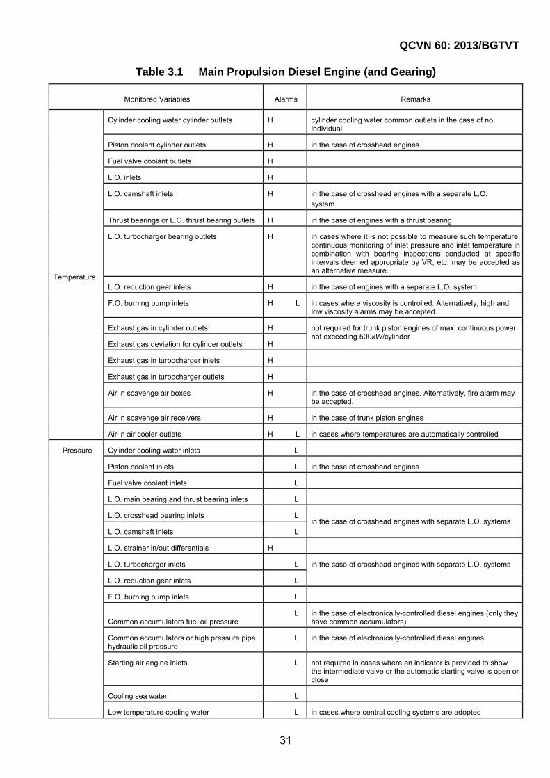
Main propulsion diesel engines are to be provided with alarm devices which activate in the event of any of those abnormal conditions given in Table 3.1.
2 Main propulsion machinery in steam turbine ships
(1) Safety devices
Safety devices are to be provided to shut off steam supplies to main propulsion steam turbines under the following conditions:
(a) Over-speed;
(b) Pressure drops of lubricating oil;
(c) Low vacuum of main condensers;
(d) Stoppage of all main boilers.
(2) Reduction of speeds or loads
Measures are to be taken to automatically reduce speeds or loads to main propulsion machinery under the following conditions. However, in cases where alternative measures such as activating alarms to request such reductions are taken, manual reductions of speeds or loads may be accepted.
(a) Excessive vibration of rotor shafts or casings;
(b) Excessive axial displacement of rotor shafts;
(c) High condensate levels in main condensers;
(d) Excessive drops of steam pressure at inlets of turbines.
(3) Standby pumps and scoop systems
Standby pumps and scoop systems are to comply with the following (a) and (b):
(a) Standby pumps for any pumps used as auxiliary machinery essential for main propulsion are to be arranged so as to start automatically or so as to be capable of being immediately remotely started from centralized control stations or

QCVN 60: 2013/BGTVT
26
centralized monitoring and control stations on bridges under the following conditions:
(i) With respect to lubricating oil pumps, in cases where delivery pressures or flow rates of any pumps in operation fall below their predetermined values.
(ii) With respect to condensate pumps, cooling water (oil) pumps including circulating pumps for main condensers and drain pumps, in cases where delivery pressures or flow rates of any pumps in operation fall below their predetermined values or in cases where such pumps stop.
(b) In cases where scoop systems are adopted, such systems are to be arranged so as to change over automatically to circulating pumps in any abnormal conditions where those values specified in (i) to (iii) exceeds either the upper limits or lower limits of their predetermined values. However, such automatic changeover devices may not be required in cases where alarm devices designed to indicate any of those abnormal conditions mentioned above and remote changeover devices to circulating pumps are provided in centralized control stations or centralized monitoring and control stations on bridges.
(i) Ship speed;
(ii) Vacuums of the main condenser;
(iii) Indices equivalent to (i) and (ii) above.
(4) Spinning devices
Automatic spinning devices or other suitable measures are to be employed to prevent any risk of rotor distortion due to propulsion turbines being stopped for long periods of time.
(5) Alarm devices
Propulsion steam turbines are to be provided with alarm devices which activate in the event of any of those abnormal conditions given in Table 3.2.
3 Propulsion motors
(1) Safety devices
Safety devices are to be provided to shut off power supplies to propulsion motors under the following conditions:
(a) Over-speed;
(b) Pressure drops of lubricating oil;
(c) Loss of control of semiconductor converters(b)
(d) Any others as deemed necessary by VR.
(2) Reductions of speeds or loads
Measures are to be taken to automatically reduce speeds or loads to propulsion

QCVN 60: 2013/BGTVT
27
motors under the following conditions. However, in cases where alternative measures such as activating alarms to request such reductions are taken, manual reduction of speeds or loads may be accepted.
(a) Over loads;
(b) High temperatures of stator windings or inter pole windings;
(c) Abnormal stopping of cooling fans for semiconductor converters;
(d) Actuation of semiconductor protective devices for semiconductor converters;
(e) Any others as deemed necessary by VR.
(3) Standby pumps
Standby pumps for any pumps necessary for the operation of propulsion motors such as lubricating oil pumps, cooling water pumps are to be arranged so as to start automatically or so as to be capable of being immediately remotely started from centralized control stations or centralized monitoring and control stations on bridges under conditions where delivery pressures or flow rates of any pumps in operation fall below their predetermined values.
(4) Alarm devices
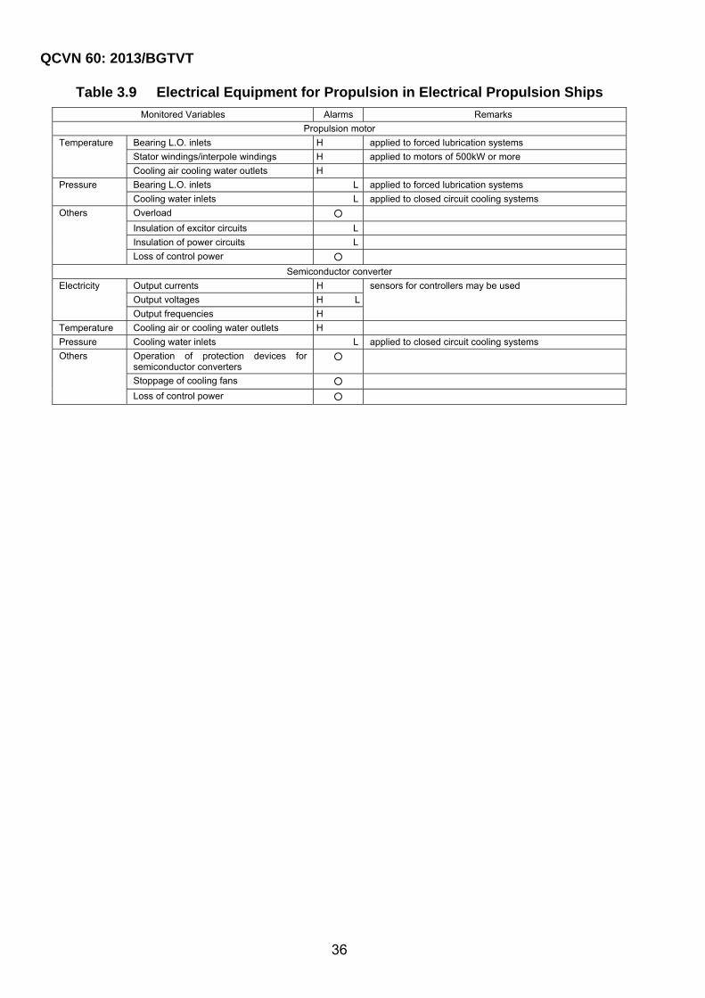
Propulsion motors are to be provided with alarm devices which activate in the event of any of those abnormal conditions given in Table 3.9.
4 Controllable pitch propellers
(1) Standby pumps
Standby pumps for the operation of controllable pitch propellers for propulsion are to be arranged so as to start automatically or so as to be capable of being immediately remotely started from centralized control stations or centralized monitoring and control stations on bridges immediately under conditions where delivery pressures or flow rates of any pumps in operation fall below their predetermined value or in cases where such pumps stop.
(2) Alarm devices
Controllable pitch propellers for propulsion are to be provided with alarm devices which activate in the event of any of those abnormal conditions given in Table 3.6.
3.3.3 Boilers
1 Safety devices
Safety devices are to comply with the following (1) and (2):
(1) Self-closing valves are to be provided in the feed water piping of main boilers, and are to operate automatically in the event of any abnormal increase of water levels in main boilers.
(2) Safety devices for low water levels in main boilers are to be put into action by means
QCVN 60: 2013/BGTVT
28
of signals from either one of two low water level detectors which are independent of each other. However, one of these detectors may be used for other purposes.
2 Standby pumps
Standby pumps for any of the following pumps necessary for the operation of main boilers and essential auxiliary boilers are to be arranged so as to start automatically or so as to be capable of being immediately remotely started from centralized control stations or centralized monitoring and control stations on bridges under conditions where delivery pressures or flow rates of any pumps in operation fall below their predetermined values or in cases where such pumps stop. This requirement need not be applied to fuel oil burning pumps for essential auxiliary boilers provided that alternative means are available to ensure normal navigation and cargo heating in the case of any failure of such fuel oil burning pumps.
(1) Feed water pumps;
(2) Fuel oil burning pumps.
3 Alarm devices
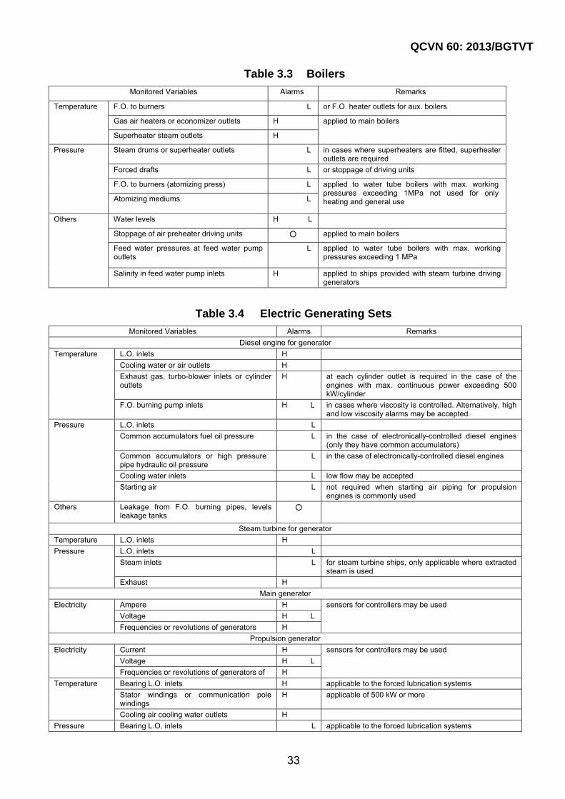
Boilers are to be provided with alarm devices which activate in the event of any of those abnormal conditions given in Table 3.3.
3.3.4 Generating sets
1 Safety devices
Safety devices for electric generating sets are to comply with the following (1) through (3):
(1) Diesel engines driving generators are to be provided with safety devices to automatically shut off fuel oil supplies to engines under the following conditions:
(a) Over-speed
(b) Pressures drop of lubricating oil
(c) Abnormal rise of oil mist concentration in crankcase in case of crosshead engines (applicable to engines of 2,250 kW maximum continuous power and above or having cylinders of more than 300 mm bore. In case where other measures considered appropriate by VR, such devices may be dispensed with.
(d) High temperatures, low pressures or low flow rates of cooling water at outlets
(2) Turbines driving generators are to be provided with safety devices to automatically shut off steam supplies to turbines under the following conditions:
(a) Over-speed;
(b) Pressures drop of lubricating oil;
(c) High exhaust gas pressures or low condenser vacuums;
(d) Abnormal vibrations (except in cases where steam is supplied by main boilers).

QCVN 60: 2013/BGTVT
29
(3) Propulsion generators are to be provided with means to automatically reduce speeds (or reduce loads) of propulsion motors in cases where propulsion generators are overloaded. However, in cases where alarm devices asking for such speed reductions (or load reductions) deemed appropriate by VR are provided, manual reduction means may be accepted.
2 Alarm devices
Electric generating sets are to be provided with alarm devices which activate in the event of any of those abnormal conditions given in Table 3.4.
3.3.5 Thermal oil installations
1 Standby pumps
Standby pumps for any of the following pumps of the thermal oil installations for essential use are to be arranged so as to start automatically or so as to be capable of being immediately remotely started from centralized control stations or centralized monitoring and control stations on bridges under conditions where delivery pressures or flow rates of any pumps in operation fall below their predetermined values or in cases where such pumps stop. This requirement need not be applied to fuel oil burning pumps provided that alternative means are available to ensure normal navigation and cargo heating in the case of any failure of such fuel oil burning pumps.
(1) Thermal oil circulating pumps;
(2) Fuel oil burning pumps.
2 Alarm devices
Thermal oil installations are to be provided with alarm devices which activate in the event of any of those abnormal conditions given in Table 3.5.
3.3.6 Prime movers driving auxiliary machinery
1 Safety measures
Prime movers driving auxiliary machinery essential for main propulsion of ships are to be arranged so as to automatically stop under the following conditions:
(a) Over-speed;
(b) Pressure drops of lubricating oil.
2 Alarm devices
Prime movers driving auxiliary machinery essential for main propulsion of ships are to be provided with alarm devices which activate in the event of any of those abnormal conditions given in Table 3.7.
3.3.7 Other Machinery
1 Air compressors
QCVN 60: 2013/BGTVT
30
Air compressors are to be arranged so as to automatically stop in the event of pressure drops of lubricating oil.
2 Heat exchangers
The following heat exchangers used for main propulsion machinery, main boilers, essential auxiliary boilers, generators and prime movers driving auxiliary machinery essential for main propulsion of ships are to be provided with temperature control devices in order to regulate the temperatures of lubricating oils, coolants and fuel oils within a predetermined range:
(1) Lubricating oil coolers;
(2) Coolers for cylinder cooling water;
(3) Coolers for piston coolant;
(4) Coolers for fuel valve coolant;
(5) Fuel oil heaters;
(6) Heaters for fuel oil purifiers;
(7) Heaters for lubricating oil purifiers.
3 Alarm devices
Other machinery is to be provided with alarm devices which activate in the event of any of those abnormal conditions given in Table 3.8.
QCVN 60: 2013/BGTVT
31
Table 3.1 Main Propulsion Diesel Engine (and Gearing)
Monitored Variables Alarms Remarks
Temperature
Cylinder cooling water cylinder outlets H cylinder cooling water common outlets in the case of no individual
Piston coolant cylinder outlets H in the case of crosshead engines
Fuel valve coolant outlets H
L.O. inlets H
L.O. camshaft inlets H in the case of crosshead engines with a separate L.O.
system
Thrust bearings or L.O. thrust bearing outlets H in the case of engines with a thrust bearing
L.O. turbocharger bearing outlets H in cases where it is not possible to measure such temperature, continuous monitoring of inlet pressure and inlet temperature in combination with bearing inspections conducted at specific intervals deemed appropriate by VR, etc. may be accepted as an alternative measure.
L.O. reduction gear inlets H in the case of engines with a separate L.O. system
F.O. burning pump inlets H L in cases where viscosity is controlled. Alternatively, high and low viscosity alarms may be accepted.
Exhaust gas in cylinder outlets H not required for trunk piston engines of max. continuous power not exceeding 500kW/cylinder
Exhaust gas deviation for cylinder outlets H
Exhaust gas in turbocharger inlets H
Exhaust gas in turbocharger outlets H
Air in scavenge air boxes H in the case of crosshead engines. Alternatively, fire alarm may be accepted.
Air in scavenge air receivers H in the case of trunk piston engines
Air in air cooler outlets H L in cases where temperatures are automatically controlled
Pressure
Cylinder cooling water inlets L
Piston coolant inlets L in the case of crosshead engines
Fuel valve coolant inlets L
L.O. main bearing and thrust bearing inlets L
L.O. crosshead bearing inlets L in the case of crosshead engines with separate L.O. systems
L.O. camshaft inlets L
L.O. strainer in/out differentials H
L.O. turbocharger inlets L in the case of crosshead engines with separate L.O. systems
L.O. reduction gear inlets L
F.O. burning pump inlets L
Common accumulators fuel oil pressure L in the case of electronically-controlled diesel engines (only they
have common accumulators)
Common accumulators or high pressure pipe hydraulic oil pressure
L in the case of electronically-controlled diesel engines
Starting air engine inlets L not required in cases where an indicator is provided to show the intermediate valve or the automatic starting valve is open or close
Cooling sea water L
Low temperature cooling water L in cases where central cooling systems are adopted

QCVN 60: 2013/BGTVT
32
Table 3.1 Main Propulsion Diesel Engine (and Gearing) (continued)
Monitored Variables Alarms Remarks
Others
Oily contamination of cylinder cooling water
H in cases where cylinder cooling water is used in F.O. or
L.O. heat exchangers
Piston coolant flow rate for cylinder outlets L in the case of crosshead engines
Non flow alarms may be accepted. Other alternative means may be accepted where it is impracticable to monitor piston coolant flows due to engine design.
Cylinder oil flow rates for lubricators L non-flows may be accepted
Scavenge air receiver water levels H alternative means may be accepted
Wrong way 〇 in the case of self-reversing engines
Failure of engine starting 〇
Leakage from F.O. burning pipes, level in leakage tanks
〇
Note : H and L mean high and low. 〇 means abnormal condition occurred. Same meaning is applied to Table 3.1 to 3.9.
Table 3.2 Main Propulsion Steam Turbine (and Gearing, Main Condenser)
Monitored Variables Alarms Remarks
Temperature
L.O. inlets H
Rotor bearings or L.O. outlets H
Rotor thrust bearings or L.O. outlets H
Reduction gear bearings or L.O. outlets H
Thrust bearings or L.O. outlets H
Pressure
L.O. inlets L
Main condenser vacuums L
Gland steam H L
Cooling gear water L or flow
Others
Levels in main condensers H applied when main condensers are situated on the same level on which turbines are situated
Rotor vibrations or casing vibrations H sensors for safety systems may be used
Rotor axial displacement H
QCVN 60: 2013/BGTVT
33
Table 3.3 Boilers
Monitored Variables Alarms Remarks
Temperature
F.O. to burners L or F.O. heater outlets for aux. boilers
Gas air heaters or economizer outlets H applied to main boilers
Superheater steam outlets H
Pressure
Steam drums or superheater outlets L in cases where superheaters are fitted, superheater outlets are required
Forced drafts L or stoppage of driving units
F.O. to burners (atomizing press) L applied to water tube boilers with max. working pressures exceeding 1MPa not used for only heating and general use Atomizing mediums L
Others
Water levels H L
Stoppage of air preheater driving units ○ applied to main boilers
Feed water pressures at feed water pump outlets
L applied to water tube boilers with max. working pressures exceeding 1 MPa
Salinity in feed water pump inlets H applied to ships provided with steam turbine driving generators
Table 3.4 Electric Generating Sets
Monitored Variables Alarms Remarks
Diesel engine for generator
Temperature
L.O. inlets H
Cooling water or air outlets H
Exhaust gas, turbo-blower inlets or cylinder outlets
H at each cylinder outlet is required in the case of the engines with max. continuous power exceeding 500 kW/cylinder
F.O. burning pump inlets H L in cases where viscosity is controlled. Alternatively, high and low viscosity alarms may be accepted.
Pressure
L.O. inlets L
Common accumulators fuel oil pressure L in the case of electronically-controlled diesel engines (only they have common accumulators)
Common accumulators or high pressure pipe hydraulic oil pressure
L in the case of electronically-controlled diesel engines
Cooling water inlets L low flow may be accepted
Starting air L not required when starting air piping for propulsion engines is commonly used
Others
Leakage from F.O. burning pipes, levels leakage tanks
○
Steam turbine for generator
Temperature L.O. inlets H
Pressure
L.O. inlets L
Steam inlets L for steam turbine ships, only applicable where extracted steam is used
Exhaust H
Main generator
Electricity
Ampere H sensors for controllers may be used
Voltage H L
Frequencies or revolutions of generators H
Propulsion generator
Electricity
Current H sensors for controllers may be used
Voltage H L
Frequencies or revolutions of generators of H
Temperature
Bearing L.O. inlets H applicable to the forced lubrication systems
Stator windings or communication pole windings
H applicable of 500 kW or more
Cooling air cooling water outlets H
Pressure Bearing L.O. inlets L applicable to the forced lubrication systems

QCVN 60: 2013/BGTVT
34
Table 3.5 Thermal Oil Installations
Monitored Variables Alarms Remarks
F.O.
Pressure, burner inlets L
Temperature burner inlets L
Thermal oil
Temperatures H
Flows or pressure differences between outlets and inlets of heaters
L
Levels in expansion tanks L
Others Flame failure ○
Table 3.6 Controllable Pitch Propellers
Monitored Variables Alarms Remarks
Hydraulic oil Tanks, levels L
Pressures L
Table 3.7 Engine Driving Auxiliary Machinery
Monitored Variables Alarms Remarks
Diesel engines
Temperature
L.O. inlets H
Cooling water outlets H low pressures/flows may be accepted
Exhaust gas, turbo charger inlets or cylinder outlets
H
F.O. burning pump inlets H L in cases where viscosity is controlled. Alternatively, high and low viscosity alarms may be accepted.
Pressure L.O. inlets L
Common accumulators fuel oil pressure
L in the case of electronically-controlled diesel engines (only they have common accumulators)
Common accumulators or high pressure pipe hydraulic oil pressure
L in the case of electronically-controlled diesel engines
Cooling water outlets L low flows or high temperatures at cooling water outlets may be accepted
Others
Leakage from F.O. burning pipes, levels in leakage tanks
○
Turbine
Temperature L.O. inlets H
Pressure
L.O. inlets L
Steam inlets L for steam turbine ships, only applicable when extracted steam is used
Exhaust steam H

QCVN 60: 2013/BGTVT
35
Table 3.8 Other Machinery
Monitored Variables Alarms Remarks
Auxiliaries
Distilling plants, salinity H
Purifiers, malfunctions ○
F.O. or L.O. heater outlets, temperatures H or heater outlets, flow lows
Cooling sea water pressures L in cases where central cooling systems are adopted for the main propulsion machinery
Condensate pump outlets, pressures L or stoppage of driving units for steam turbine ships
Condensate pump outlets, salinity H
Drain pump outlets, salinity H
External desuperheaters, steam temperatures H L L is required when the steam in used for auxiliary turbines relation to propulsion
Deaerator, levels H L
Tanks
F.O.
Settling tanks, levels H L H is required in the case of automatic filling only, L is required to tanks having capacity not enough to 24 hours continuous operation
Service tanks, levels H L
Drain tanks levels H
Sludge tanks, levels H
Settling tanks, temperatures H applied to tanks where heating devices are provided
Service tanks, temperatures H
L.O. and
control oil
Sump tanks for propulsion engines, levels
L
Drain tanks, levels H
Sludge tanks, levels H
Gravity tanks, levels L applied to oil bath type stern tube bearings, exhaust driven turbo blowers, and reduction gear for propulsion steam turbines
Water
Cooling water expansion (makeup) tanks, levels
L
Purifier water tanks, levels L
Cascade tanks, levels L applied to diesel ships
Atmospheric drain tanks, levels H L applied to steam turbine ships
Distilled water tanks, levels L
Air
Starting air tanks for propulsion engines, pressures
L
Starting air tanks for generator diesel engines, pressures
L applied to steam turbine ships
Control and safety systems
Control system hydraulic pressures L not required in cases where it is integrated with controlled objects
Control system pneumatic pressures L not required in cases where starting air is used without decompressing
Control system electric sources ○
Safety system hydraulic pressure systems L
Safety system pheumatic pressures L not required in cases where starting air is used without decompressing
Safety system electric sources ○
Alarm system electric sources ○
Hydraulic coupling oil in main shafting systems, pressures
L
Main shaftings
Temperature Stern tube bearings or bearing oil in oil baths
H or stern tube outlet oil when forced circulation systems are used, applied to oil lubrication systems
Others Critical speed ○
QCVN 60: 2013/BGTVT
36
Table 3.9 Electrical Equipment for Propulsion in Electrical Propulsion Ships
Monitored Variables Alarms Remarks
Propulsion motor
Temperature
Bearing L.O. inlets H applied to forced lubrication systems
Stator windings/interpole windings H applied to motors of 500kW or more
Cooling air cooling water outlets H
Pressure
Bearing L.O. inlets L applied to forced lubrication systems
Cooling water inlets L applied to closed circuit cooling systems
Others
Overload ○
Insulation of excitor circuits L
Insulation of power circuits L
Loss of control power ○
Semiconductor converter
Electricity
Output currents H sensors for controllers may be used
Output voltages H L
Output frequencies H
Temperature Cooling air or cooling water outlets H
Pressure Cooling water inlets L applied to closed circuit cooling systems
Others
Operation of protection devices for semiconductor converters
○
Stoppage of cooling fans ○
Loss of control power ○

QCVN 60: 2013/BGTVT
37
CHAPTER 4 MONITORING AND CONTROL SYSTEMS FOR PERIODICALLY UNATTENDED MACHINERY SPACES
4.1 General
4.1.1 Scope
The requirements given in this Chapter apply to monitoring and control systems for periodically unattended machinery spaces to be installed in M0-ships.
4.2 Monitoring and control systems for periodically unattended machinery spaces
4.2.1 General
1 With respect to M0-ships, monitoring and control systems for periodically unattended machinery spaces are to be installed in order to ensure the safe operation of main propulsion machinery under all sailing conditions including maneuvering to the same extent that can be achieved by means of manual control under direct supervision. Systems are to be capable of performing unattended machinery operations for at least 24 consecutive hours.
2 Monitoring and control systems for periodically unattended machinery spaces are to include those devices and systems specified in this Chapter as well as centralized monitoring and control systems for machinery specified in Chapter 3.
3 Centralized monitoring and control systems for machinery used as monitoring and control systems for periodically unattended machinery spaces are to comply with the following requirements in addition to those requirements specified in Chapter 3.
(1) Standby pumps specified in the following requirements are to be arranged so as to be capable of being automatically started.
(a) 3.3.2-1(3);
(b) 3.3.2-2(3)(a);
(c) 3.3.2-3(3);
(d) 3.3.2-4(1);
(e) 3.3.3-2;
(f) 3.3.5-1;
(g) 18.2.2-2(3) Part 3 Section II QCVN 21: 2010/BGTVT.
(2) Those circulating pumps specified in 3.3.2-2(3)(b) are to be arranged so as to be capable of being automatically changed over.
QCVN 60: 2013/BGTVT
38
4.2.2 Bridge control devices or centralized monitoring and control systems for machinery installed in bridge
1 Bridge control devices specified in 18.3.3 Part 3 Section II QCVN 21: 2010/BGTVT or centralized monitoring and control systems for machinery are to be provided on bridges.
2 Bridge control devices or centralized monitoring and control systems for machinery installed on bridges are to include the following devices. In cases where special approval, taking into consideration the kind of main propulsion machinery, etc., from the Society has been received, these devices may be dispensed with.
(1) Any program control devices or their equivalent which allow speeds of main propulsion machinery to be rapidly increased or reduced in order to ensure that main propulsion machinery are free from any undue mechanical and thermal stress
(2) Bypass devices to temporarily override the function of those devices mentioned in (1) above with indicators to show their activation
4.2.3 Alarm devices on bridge
1 In cases where bridge control devices are installed, the following alarm devices are to be provided on bridges in addition to those required by the requirements specified in 18.3.3 Part 3 Section II QCVN 21: 2010/BGTVT.
(1) Alarm devices for main propulsion machinery or controllable pitch propellers, electric generating sets and auxiliary machinery;
(2) Bilge alarm devices;
(3) Alarm devices for any prolonged running in those critical speed ranges specified in Table 3.9.
2 In cases where centralized monitoring and control systems for machinery are installed on bridges, all alarm devices are to comply with the following requirements:
(1) At least the following visual alarms of those alarm devices required by 3.2.2(6) are to be provided in positions where they can be easily confirmed from places used to control operating handles of main propulsion machinery.
(a) Alarms for automatic stopping;
(b) Alarms for automatic reduction or demanding reduction of speeds or loads;
(c) Alarms for failures of remote control systems specified in 18.3.2-3(1) Part 3 Section II QCVN 21: 2010/BGTVT;
(d) Alarms for low starting air pressures specified in 18.3.2-4(3) Part 3 Section II QCVN 21: 2010/BGTVT;
(e) Alarms for failures of remote starting specified in Table 3.1;
(f) Alarms for any prolonged running in those critical speed ranges specified in Table 3.9.
QCVN 60: 2013/BGTVT
39
(2) Visual alarms of those alarm devices required by 3.2.2(6) and (9), excluding those specified in (1) above, are to be arranged so that working conditions of machinery can be perceived at a glance from places used to control operating handles of main propulsion machinery. In cases where it is impracticable to comply with this requirement, additional visual alarms which may be of group indication are to be provided.
3 Visual alarms of alarm devices for main propulsion machinery or controllable pitch propellers, electric generating sets and auxiliary machinery may be displayed as group alarms. However, any visual alarms for automatic stopping and for speed or load reductions (either automatic or demanding) of main propulsion machinery are to be displayed individually.
4 In cases where the alarm devices for demanding reduction of speeds or loads are provided for main propulsion machinery, the individually displayed visual alarms specified in -3 may be substituted for devices deemed appropriate by VR.
4.2.4 Centralized monitoring and control station on bridge
In cases where centralized monitoring and control stations on bridges have been installed, the shapes, sizes, arrangements, etc. of such stations are to comply with the following requirements:
(1) They are to be located on the same deck floor and not to be provided with any partition walls (steel walls, wooden walls, glass walls, etc.) inside of the station except in cases where specially approved by VR.
(2) Any audible alarms and voice orders issued from positions inside of such stations are to be capable of being clearly and distinctly heard from any position inside such stations.
4.3 Safety measures, etc.
4.3.1 Air Compressors
Automatic control devices are to be provided for the following air compressors so as to maintain the pressure in any air reservoirs in predetermined ranges.
(1) Starting air compressors;
(2) Controlling air compressors used for charging air to control air reservoirs.
4.3.2 Means of communication
In the case of ships with centralized monitoring and control stations on bridges, means of vocal communication which are operable even in the event of any failures of main electrical power supplies are to be provided for any centralized monitoring and control stations on bridges, local control positions (or sub-control stations, if provided.) of main propulsion machinery or controllable pitch propellers, and engineers accommodations. For the other ships, this means is to be provided among the wheelhouse, the centralized control station, the local control position of main propulsion machinery or controllable pitch propellers, and the engineers accommodation.

QCVN 60: 2013/BGTVT
40
4.3.3 Alarm Systems
Alarm systems are to comply with the following requirements:
(1) Alarm systems are to be provided with automatic changeover arrangements for switching power supplies from normal power sources to independent standby power sources in the event of any normal power failures.
(2) Any failures of those normal or standby power sources specified in (1) above are to be indicated by independent alarms.
(3) Alarm devices (visual alarms may be displayed as group alarms) for main propulsion machinery, electric generating sets, and auxiliary machinery essential for main propulsion are to be provided in engineer accommodations.
(4) Alarm devices provided in engineer accommodations are to comply with the following requirements:
(a) Alarms are to be provided in engineer public rooms.
(b) Alarms are also to be provided in the respective cabins of engineers with connections to such cabins through selector switches, to ensure that any alarms can be provided to at least those cabins of any engineers on watch.
(c) Alarm devices are to be capable of activating those engineer alarms required by 1.3.8 Part 3 Section II QCVN 21: 2010/BGTVT if confirmation of such alarms has not been completed within a predetermined amount of time.
(5) Audible alarm devices which indicate any possible failures in the machinery and equipment specified in 1.1.5(12)(a) through (g) are to be provided in spaces where they are installed.
(6) In the cases of ships provided with centralized monitoring and control stations on bridges, local silencing of audible alarms from engineer accommodations is not to cause any silencing of those audible alarms required by (5) above and any canceling of those audible and visual alarms in the centralized monitoring and control stations on bridges. For all other ships, local silencing of audible alarms from bridges or engineer accommodations is not to cause any silencing of those audible alarms required by (5) above and any canceling of those audible and visual alarms in centralized control stations.
(7) Alarm systems are to have functions to notify those persons on watch on bridges of the following items upon any failures of the machinery and equipment specified in 1.1.5(12)(a) through (g) during their unattended operation.
(a) Occurrence of any such failures;
(b) Acknowledgement of any such failures;
(c) Restoration from any such failures.
QCVN 60: 2013/BGTVT
41
CHAPTER 5 SPECIFIC AUTOMATION EQUIPMENT
5.1 General
5.1.1 Scope
The requirements in this Chapter apply to all of the specific automation equipment to be
installed on M0.A-ships, M0.B-ships, M0.C-ships or M0.D-ships.
5.2 Specific Automation Equipment
5.2.1 Class A specific automation equipment
In the cases of M0.A-ships, all of the specific automation equipment specified in 5.3.1, 5.3.2, 5.3.4 through 5.3.7, 5.3.11 and 5.3.17 (except sub-paragraph (2)) are to be provided. However, in cases where considered appropriate by VR, taking into account the service or the purpose, etc. of ships, some equipment may be omitted.
5.2.2 Class B specific automation equipment
In the case of M0.B-ships, all of the specific automation equipment specified in 5.3.1, 5.3.2, 5.3.4 through 5.3.12 and 5.3.17 are to be provided. However, in cases where considered appropriate by VR taking into account the service or the purpose, etc. of ships, some equipment may be omitted.
5.2.3 Class C specific automation equipment
In the cases of M0.C-ships, all of the specific automation equipment specified in 5.3.1, 5.3.3 through 5.3.15 and 5.3.17 are to be provided. However, in cases where considered appropriate by VR taking into account the service or the purpose, etc. of ships, some equipment may be omitted.
5.2.4 Class D specific automation equipment
In the case of M0.D-ships, all of the specific automation equipment specified in 5.3.1, 5.3.3 through 5.3.17 is to be provided. However, in cases where considered appropriate by VR taking into account the service or the purpose, etc. of the ship, some equipment may be omitted.
5.3 Standards for specific automation equipment
5.3.1 Remote-controlled fuel oil filling arrangements
Remote-controlled fuel oil filling arrangements, in cases where taking on fuel oil (limited to those cases where filling fuel oil for main propulsion machinery (including main boilers)), are to be provided with the following items located as close to each other as practicable. However, the provision of item (3) may be omitted when the Society considers it acceptable in consideration of fuel oil tank and valve arrangements.

QCVN 60: 2013/BGTVT
42
(1) Level monitoring systems of fuel oil tanks;
(2) Limit level alarm systems of fuel oil tanks;
(3) Control systems of valves required to be operated for filling fuel oil;
(4) Other control systems necessary for filling fuel oil.
5.3.2 Remote-controlled mooring arrangements
In cases where mooring winches are remotely controlled, remote-controlled mooring arrangements are to be capable of effectively controlling three or more mooring lines respectively both the bows and sterns of ships.
5.3.3 Independent remote-controlled mooring arrangements
Independent remote-controlled mooring arrangements are to be capable of controlling all drums of mooring winches independently from their remote-control positions, in addition to those requirements given in 5.3.2.
5.3.4 Automatic steering system
In cases where the steering gear is operated with automatic pilots, automatic steering systems are to comply with the following requirements:
(1) By interlocking with magnetic compasses or gyrocompasses, the headings of ships are to be maintained automatically at preset courses.
(2) In cases where steering methods are changed over from manual to automatic steering, headings of ships are to be capable of being automatically brought to preset courses.
(3) Operation is to be able to be performed easily and accurately.
(4) Except for course setting controls, actuation of any other controls is not to significantly affect the course of any ships.
(5) Means are to be incorporated to prevent any unnecessary activation of rudders due to normal yaw motion.
(6) Indication that automatic pilots are running is to be provided.
(7) Means are to be provided to enable rudder angle limitation and to indicate when rudders reach their preset angle limits.
(8) Audible and visual alarms are to be issued on navigation bridges in cases where headings of ships have deviated in a way exceeding the preset amounts of course deviation.
(9) Audible and visual alarms are to be issued on navigating bridges in order to indicate any failure in power supplies to automatic pilots and those alarm systems specified in (8) above.
(10) Any other items considered necessary by VR.

QCVN 60: 2013/BGTVT
43
5.3.5 Remote-controlled handling system for liquid cargo in bulk
1 Remote-controlled handling systems for liquid cargo in bulk are to be provided with the following centralized functions in cases where the operation of such cargo pumps is performed by remote control:
(1) Speed controls or start/stop controls for cargo pumps;
(2) Controls for any equipment necessary for cargo loading/unloading;
(3) Monitoring of levels of cargo in cargo tanks;
(4) Monitoring of alarms for cargo pumps;
(5) Monitoring of alarms for prime movers for cargo pumps;
(6) Monitoring of high temperature alarms for stuffing boxes provided at bulkhead penetrations of cargo pump rooms;
(7) Monitoring of alarms for other control systems considered necessary by VR.
2 Alarm systems of cargo pumps and their prime movers specified in -1 above are to be capable of issuing alarms in the following cases:
(1) In the case of steam turbines driving cargo pumps
(a) In cases where turbine speed increases abnormally and shut-off devices are being operated automatically.
(b) In cases where exhaust steam pressures increase abnormally.
(2) In the case of prime movers driving cargo pumps installed in dangerous areas
(a) In cases where temperatures of bearings or lubricating oils increase abnormally.
(b) In cases where lubricating oil pressures fall abnormally (only in the case of forced lubrication systems).
(3) In the case of cargo pumps installed in dangerous areas
(a) In cases where temperatures of bearings or lubricating oils increase abnormally.
(b) In cases where lubricating oil pressures fall abnormally (only in the case of forced lubrication systems).
(c) In cases where temperatures of cargo pump casings increase abnormally.
5.3.6 Remote-controlled ballasting/deballasting arrangements
1 Remote-controlled ballasting/deballasting arrangements are to be provided with the following centralized functions in cases where the operation of such ballast pumps is performed by remote control:
(1) Speed controls or start/stop of ballast pumps
(2) Controls for any equipment necessary for ballasting/deballasting operations
(3) Monitoring of levels of ballast water in the ballast tanks
QCVN 60: 2013/BGTVT
44
(4) Monitoring of alarms for ballast pumps
(5) Monitoring of alarms for any prime movers of ballast pumps
(6) Monitoring of high temperature alarms for stuffing boxes provided at bulkhead penetrations of cargo pump rooms
2 Alarm systems for ballast pumps and their prime movers specified in -1 above are to be capable of issuing alarms in the following cases:
(1) In the case of steam turbines driving ballast pumps
(a) In cases where turbine speeds increase abnormally and shut-off devices are operated automatically.
(b) In cases where exhaust steam pressures increase abnormally.
(2) In the case of prime movers driving ballast pumps installed in dangerous areas
(a) In cases where temperatures of bearings or lubricating oils increase abnormally.
(b) In cases where lubricating oil pressures fall abnormally (only in the case of forced lubrication systems).
(3) In the case of ballast pumps installed in dangerous areas
(a) In cases where temperatures of bearings or lubricating oils increase abnormally.
(b) In cases where lubricating oil pressures fall abnormally (only in the case of forced lubrication systems).
5.3.7 Power-operated opening/closing appliances
Power-operated opening/closing appliances are to comply with the following requirements for the operation of opening and closing bow doors, stern doors, side doors, ramp ways attached permanently, or hatch covers (excluding pontoon type) provided on weather decks (hereinafter referred to as the “side doors, etc”. in the Regulation).
(1) Opening and closing operations of side doors, etc. are to be readily made at the control positions of such opening and closing operations.
(2) Opening conditions and closing conditions of side doors, etc. are to be verified at the control positions of such opening and closing operations.
(3) In cases where deemed necessary by VR, means to ensure safety during opening and closing operations are to be provided.
5.3.8 Monitoring device of refrigerating containers
Monitoring devices of refrigerating containers are to be capable of carrying out the following functions for carrying refrigerating containers loaded with refrigerated cargo:
(1) Monitoring of the operating conditions of refrigerating machinery;
(2) Monitoring of the working conditions of defrosting devices;

QCVN 60: 2013/BGTVT
45
(3) Monitoring of the alarms and the range of inside temperatures of refrigerating containers.
5.3.9 Emergency towing rope winches
Emergency towing rope winches are to be capable of operating easily to heave emergency towing ropes, which are arranged at times of berthing.
5.3.10 Cargo hose handling winches
Cargo hose handling winches are to be capable of being easily controlled in the case of connecting or disconnecting cargo hoses.
5.3.11 Automatic recording devices
Automatic recording devices are to be capable of automatically recording the operating conditions of main propulsion machinery.
5.3.12 Centralized machinery monitoring systems
Centralized machinery monitoring systems are to be capable of clearly indicating at navigation bridges lubricating oil pressures, cooling water temperatures and any other necessary information in order to monitor the conditions of main propulsion machinery, prime movers for driving generators (excluding emergency generators), main boilers, essential auxiliary boilers and other machinery which affects the propulsion of ships.
5.3.13 Centralized machinery control systems
Centralized machinery control systems are to be capable of effectively controlling main propulsion machinery, prime movers for driving generators (excluding emergency generators), main boilers, essential auxiliary boilers and devices which are necessary in order to operate such machinery from navigation bridges.
5.3.14 Power-operated pilot ladder winding appliance
Power-operated pilot ladder winding appliances are to be capable of easy operation in winding ladders for pilots at their control positions.
5.3.15 Fixed deck washing arrangements
Fixed deck washing arrangements are to comply with the following requirements:
(1) Fixed deck washing arrangements are to be capable of washing decks and hatch covers.
(2) Deck washing machines are to have enough strength against their working pressures and enough corrosion resistance to sea water.
(3) Pipes for washing water are to be firmly fixed to hulls.
5.3.16 Bridge wing control devices
Bridge wing control devices are to comply with the following requirements:
QCVN 60: 2013/BGTVT
46
(1) Bridge wing control devices are to be capable of effectively controlling main propulsion machinery or controllable pitch propellers and steering systems at bridge wings.
(2) Bridge wing control devices are to comply with those requirements for bridge control devices specified in 18.3.3 Part 3 Section II QCVN 21: 2010/BGTVT, except in cases where such bridge control devices or centralized monitoring and control systems for machinery installed on bridges can be used as bridge wing control devices.
(3) Bridge wing control devices are to be provided with rudder angle indicators. However, this requirement may not apply in cases where rudder angle indicators which are easily read from control stations on bridge wings are installed.
5.3.17 Navigational equipment and radio communication equipment
1 Type approval is to be required for equipment listed below in accordance with those standards considered acceptable by VR. However, equipment approved by the Government of the State whose flag the ship is entitled to fly under, other Contracting Governments of the SOLAS Convention or any parties approved by those Governments mentioned above or complying with those International Standards recognized by VR may be exempted from these requirements as deemed appropriate by VR.
(1) Global positioning system (GPS) receiver equipment;
(2) Automatic radar plotting aids (ARPAs);
(3) Maritime satellite communication equipment.

QCVN 60: 2013/BGTVT
47
III REGULATIONS ON MANAGEMENT
1.1 General
1.1.1 Additional notations
1 If the ship has centralized monitoring and control systems for main engine and essential auxiliary engine complying with requirements of the Regulation, an additional notation “MC” is affixed to the characters of classification as specified in Chapter 2 Part 1A Section II QCVN 21: 2010/BGTVT.
2 If the ship has monitoring and control systems for periodically unattended machinery spaces complying with requirements of the Regulation, an additional notation “M0” is affixed to the characters of classification as specified in Chapter 2 Part 1A Section II QCVN 21: 2010/BGTVT.
3 If the ship has Class A specific automation equipment complying with requirements of the Regulation, an additional notation “M0.A” is affixed to the characters of classification as specified in Chapter 2 Part 1A Section II QCVN 21: 2010/BGTVT.
4 If the ship has Class B specific automation equipment complying with requirements of the Regulation, an additional notation “M0.B” is affixed to the characters of classification as specified in Chapter 2 Part 1A Section II QCVN 21: 2010/BGTVT.
5 If the ship has Class C specific automation equipment complying with requirements of the Regulation, an additional notation “M0.C” is affixed to the characters of classification as specified in Chapter 2 Part 1A Section II QCVN 21: 2010/BGTVT.
6 If the ship has Class D specific automation equipment complying with requirements of the Regulation, an additional notation “M0.D” is affixed to the characters of classification as specified in Chapter 2 Part 1A Section II QCVN 21: 2010/BGTVT.
1.2 Regulations on technical supervisions
The Automatic and Remote Control systems is to be subject to surveys specified in Chapter 2 Section II of this Regulation.
1.3 Certification
1.3.1 Certificate
If the system complies with this Regulation, that system is to be issued a certificate of design approval or a classification certificate together with the ship depending on particular demand.
1.3.2 Procedure for certification
Procedure for certification is to be in accordance with Circular No. 32/2011/TT-BGTVT.

QCVN 60: 2013/BGTVT
48
IV RESPONSIBILITIES OF ORGANIZATIONS, INDIVIDUALS
1.1 Responsibilities of ship owners and operators, agency of design, manufacturing, converting, renovating and repairing the systems
1.1.1 Ship owners and Operators
To implement all relevant requirements in this Regulation in manufacturing, converting, renovating, operating the system in order to ascertain and maintain good technical condition of the systems.
1.1.2 Design agency
1 To design the system in compliance with requirements of the Regulation.
2 To submit all required design documentation in accordance with requirements in the Regulation.
1.1.3 Yards of manufacturing, converting, renovating and repairing the systems
1 To be capable in terms of warehouse, manufacturing shop, building facilities etc. and competent manpower to meet requirement for new manufacture, conversions, renovations and repairs of the systems.
2 To comply with standards of quality, safety while manufacturing, converting, renovating and repairing the systems and to comply with approved design.
3 To undergo VR’s supervision on the technical quality and safety of the systems.
1.2 Responsibilities of Vietnam Register
1.2.1 Design approval, technical supervision
To assign surveyors having competence and of sufficient standard to carry out the technical supervision during manufacture, conversions, renovations, repairs and operation of the systems in accordance with technical requirements specified in this Regulation.
1.2.2 To give instructions for implementation/application
To give instructions for the application of requirements of this Regulation to ship owners and operators, yards of manufacture, conversions, renovations and repair of the systems, inspection offices of Vietnam Register throughout the country.
1.2.3 To amend and supplement the Regulation
Based on the fact, Vietnam Register is to have responsibility to petition the Ministry of Transport for amendment, supplementation of the Regulation where necessary or on schedule specified in the Law of Standards and Technical Regulations.
QCVN 60: 2013/BGTVT
49
1.3 Responsibilities of the Ministry of Transport
The Ministry of Transport (Science and Technology department) is responsible for verifying on the regular or random basis the implementation of this Regulation by relating organizations.

QCVN 60: 2013/BGTVT
50
V IMPLEMENTATION
1.1 It is the responsibility of Vietnam Register to manage the survey system, technical
supervision, classification and technical registration of Automatic and Remote Control
systems. It is also to include organizing the printing, dissemination and instructions for the
application of this Regulation to organizations and individuals falling under the scope of
this Regulation.
1.2 In case of inconsistency between the requirements in this Regulation and those in other
rules, standards or technical regulations relating to Automatic and Remote Control
systems, the requirements of this Regulation are to prevail over those of others.
1.3 In case the documents referred to in this Regulation are amended, supplemented or
replaced, the latter is to prevail over the former.
1.4 This Regulation and its amendment are to apply to Automatic and Remote Control
systems registered on or after effective date of this Regulation.
Recommended