Quasielastic Neutron Scattering
Franz Demmel
NTC 2013

Outline
• What is ‘quasielastic’ neutron scattering?
• Why we do it, illustrated with a few examples.
• What we want to do
• How we do it.
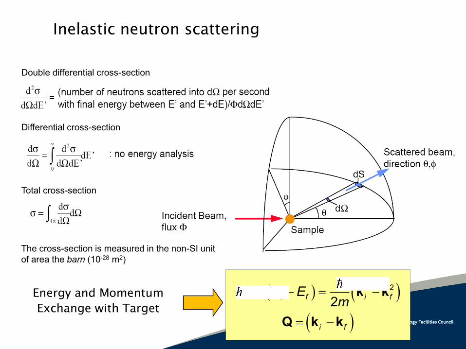
Double differential cross-section
Differential cross-section
Total cross-section
The cross-section is measured in the non-SI unit
of area the barn (10-28 m2)
Inelastic neutron scattering
2 2
2i f i f
i f
E Em
k k
Q k k
Energy and Momentum
Exchange with Target

Inelastic Neutron Scattering

N tiiti ee
NedtS
1,
01
2
1,
RQRQQ
,QS
Simulation
Theory
Experiment
The dynamical structure factor
tttdN
tG 11111 ,,1
, rrrrr
tttt ,,,, rrrr
The probability of finding a particle at position r at time t if there was a particle at r=0, t=0
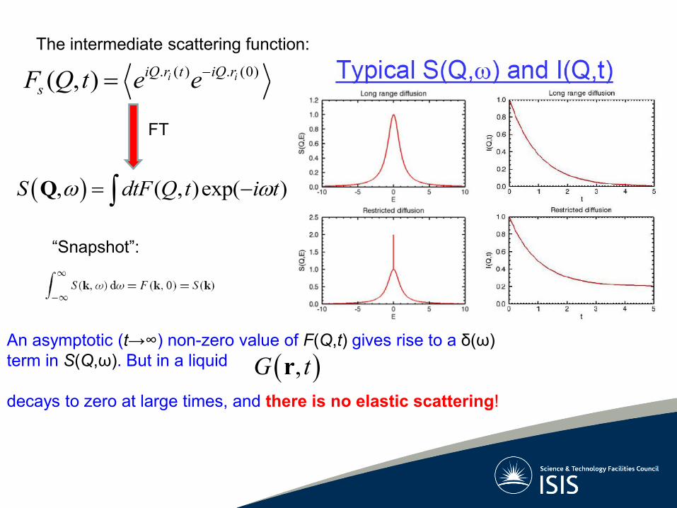
An asymptotic (t→∞) non-zero value of F(Q,t) gives rise to a δ(ω)
term in S(Q,ω). But in a liquid
decays to zero at large times, and there is no elastic scattering!
,G tr
“Snapshot”:
The intermediate scattering function:
, ( , )exp( )S dtF Q t i t Q
FT
. ( ) . (0)( , ) i iiQ r t iQ r
sF Q t e e
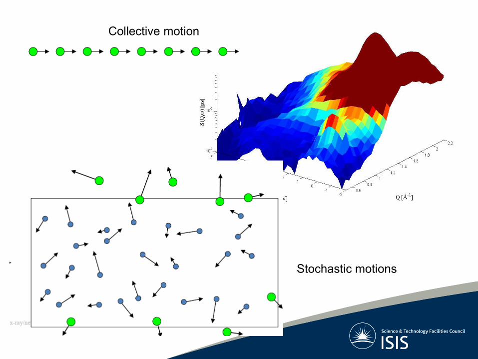
Collective motion
Stochastic motions

t
trGtrGD s
s
),(),(2
)4/exp()4(
1),( 2
2/3Dtr
DttrGs
2( , ) exp( )F Q t Q Dt
Gs(r,t) is the solution of a diffusion equation
on long length scales
Fick’s diffusion
Qs > Ql
E 0
Half Width at Half Maximum=HWHM= = DQ2
Self diffusion (long range diffusion)
2 2
1( , )S Q
“A Lorentzian”
2 2 ( , ) 6sr r G r t dr Dt
Mean square displacement
2 2[ ( ) (0)]r r t r
21
6D r
t

2 2 ( , ) 6sr r G r t dr Dt
22 2 20
0
1( )
2 2
vr v t t
Free particle, ballistic, dilute gas
Diffusion, random walk: In the time domain:
t
r2
diffusion
free particle
oscillator
actual behaviour
Liquid Argon

So the FWHM will be:
1/2
02(2ln 2) Qv Free particle:
Diffusion: 22DQ
k2
22DQ
1/2
02(2ln 2) Qv

Models for Translational Diffusion
))sin(
1(1
)(Ql
QlQ
2 21( ) (1 exp( ))
6
Q lQ
2
2( )
(1 )
DQQ
DQ
Chudley Elliott: 2( )Q DQ
Gaussian distribution:
Random jump diffusion:
Jump diffusion by Chudley Elliott
Starting with a rate equation one gets:
( , ) exp( ( ( ))I Q t t f Q
0
1( , ) ( , )
( , ) s s
s l
G r l t G r tG r t fluctuation n
t relaxation time
l
lQin
Qf )1)(exp(1
)(0
is the residence time and l the jump length
6
2lD )/exp()( 0lllla
1/
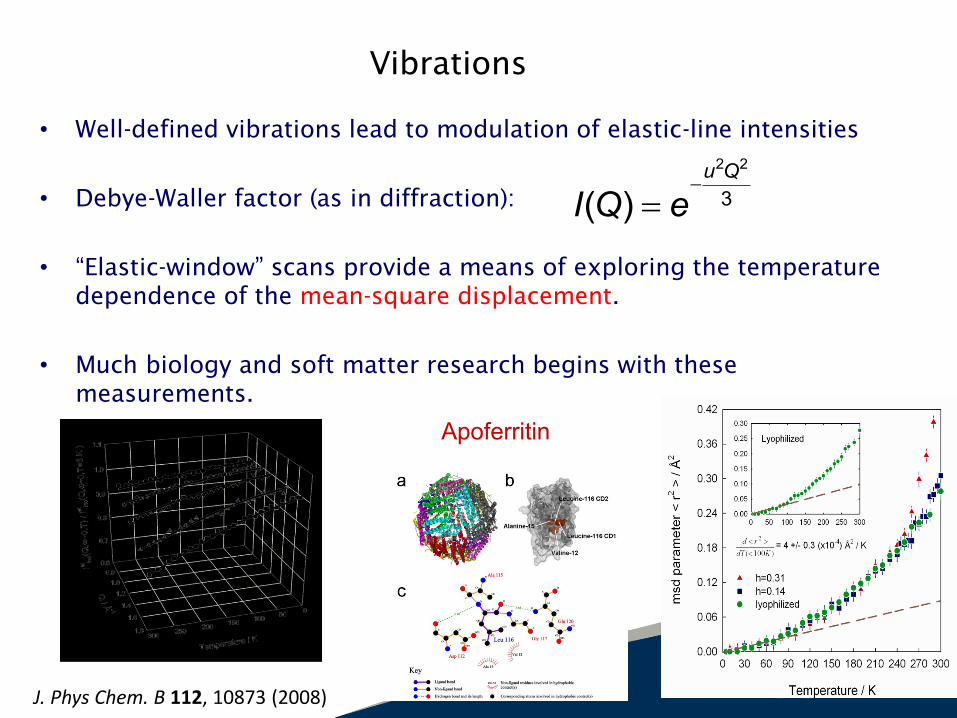
Vibrations
• Well-defined vibrations lead to modulation of elastic-line intensities
• Debye-Waller factor (as in diffraction):
• “Elastic-window” scans provide a means of exploring the temperature
dependence of the mean-square displacement.
• Much biology and soft matter research begins with these
measurements.
2 2
3( )u Q
I Q e
Apoferritin
J. Phys Chem. B 112, 10873 (2008)

Adding Degrees of Freedom
For a particle (atom), we can write (approximately):
2 2
( )3( , ) ( , ) ( , )vib
trans
u Q
Q t
particle vib transI Q t I Q t I Q t e e
I ( , ) ( , ) ( , )molecule particle rotQ t I Q t I Q t
For a molecule (with a shape), need to add rotational modes:
( , ) ( , ) ( , )molecule particle rotS Q S Q S Q
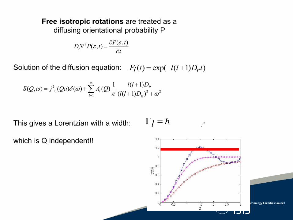
Free isotropic rotations are treated as a
diffusing orientational probability P
( ) exp( ( 1) )F t l l D tl r Solution of the diffusion equation:
This gives a Lorentzian with a width:
which is Q independent!!
( 1)l l Dl r
2
0 2 21
( 1)1( , ) ( ) ( ) ( )
( ( 1) )
Rl
l R
l l DS Q j Qa A Q
l l D
2 ( , )( , )r
P tD P t
t
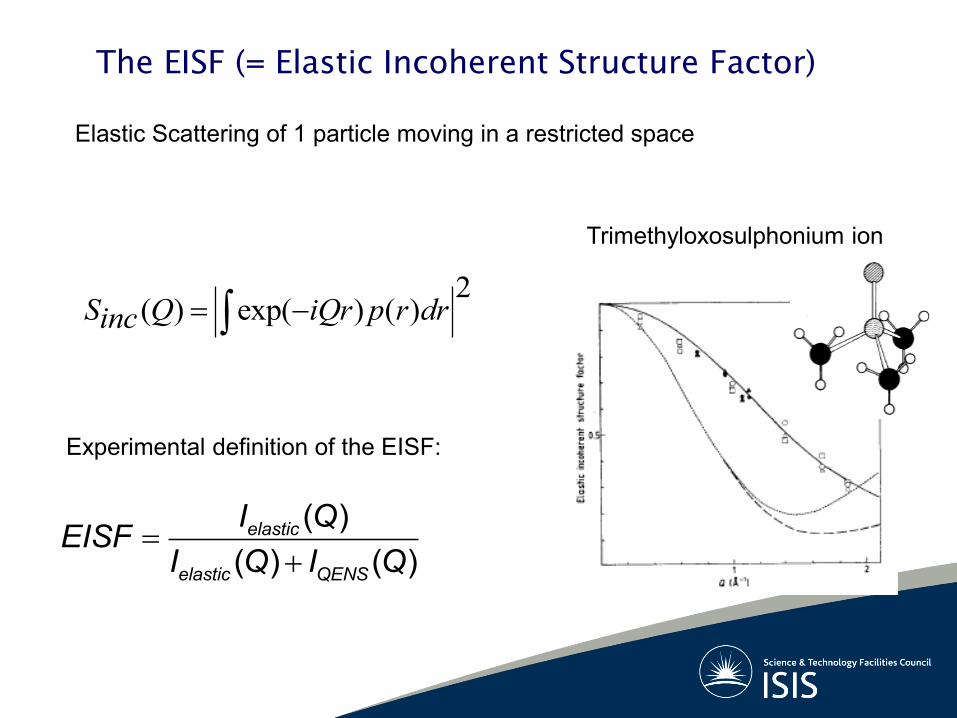
The EISF (= Elastic Incoherent Structure Factor)
( )
( ) ( )elastic
elastic QENS
I QEISF
I Q I Q
Elastic Scattering of 1 particle moving in a restricted space
2( ) exp( ) ( )S Q iQr p r drinc
Experimental definition of the EISF:
Trimethyloxosulphonium ion

Jump between two sites:
Jump probability 1/
1 2 /( , ) 1/ 2 ( )(1 ( ) 1/ 2(1 ( ))0 0 2 2(2 / )
S Q j Qd j Qd
d
Jumps among 3 sites:
r
Mean residence time
1 3/( , ) ( ) ( ) ( )0 1 2 2(3/ )
S Q A Q A Q
Example: methyl group jumps
Reorientations
Qd
Ao =½[1+sin(2Qd)/(2Qd)] EISF 1
½
EISF

2 2 2
02 2 2 21
1 ( ) 1 ( 1)( , ) e { ( ) ( ) ( ) } ....
( ) ( ( 1) )
Q u Rl
l R
Q l l DS Q j Qa A Q
Q l l D
vibrations translation rotation
EISF
A simple starting point.......
Computer Simulations
• Molecular Dynamics simulations directly map onto timescales and
dynamics probed by QENS (from ps up to ns).
• Basic idea: simulate the outcome of neutron scattering experiments
taking as input the results of an atomistic simulation.
– Predictive power for large systems (experiment design).
– Beyond model-dependent data analysis (oftentimes too simplistic for complex systems)
– Common ground for comparison with other experimental techniques (e.g., light scattering, NMR, optical spectroscopy in THz region)

A Few Examples
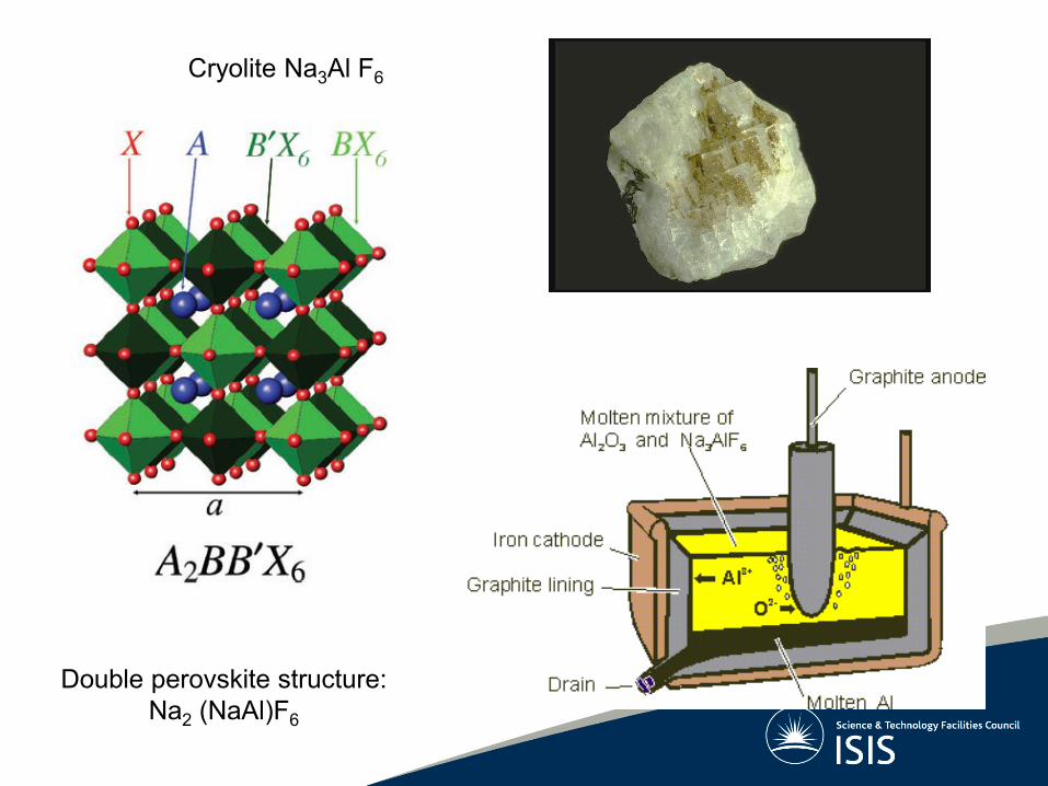
Double perovskite structure:
Na2 (NaAl)F6
Cryolite Na3Al F6

“The elastic Scan”
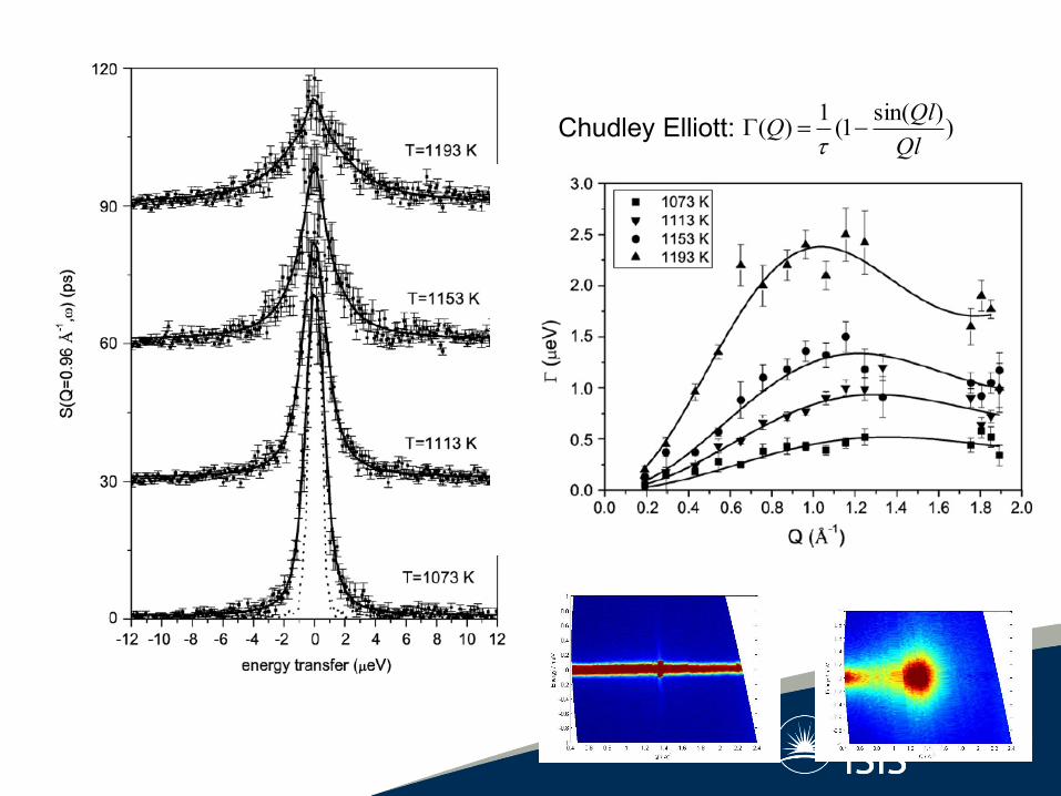
))sin(
1(1
)(Ql
QlQ
Chudley Elliott:
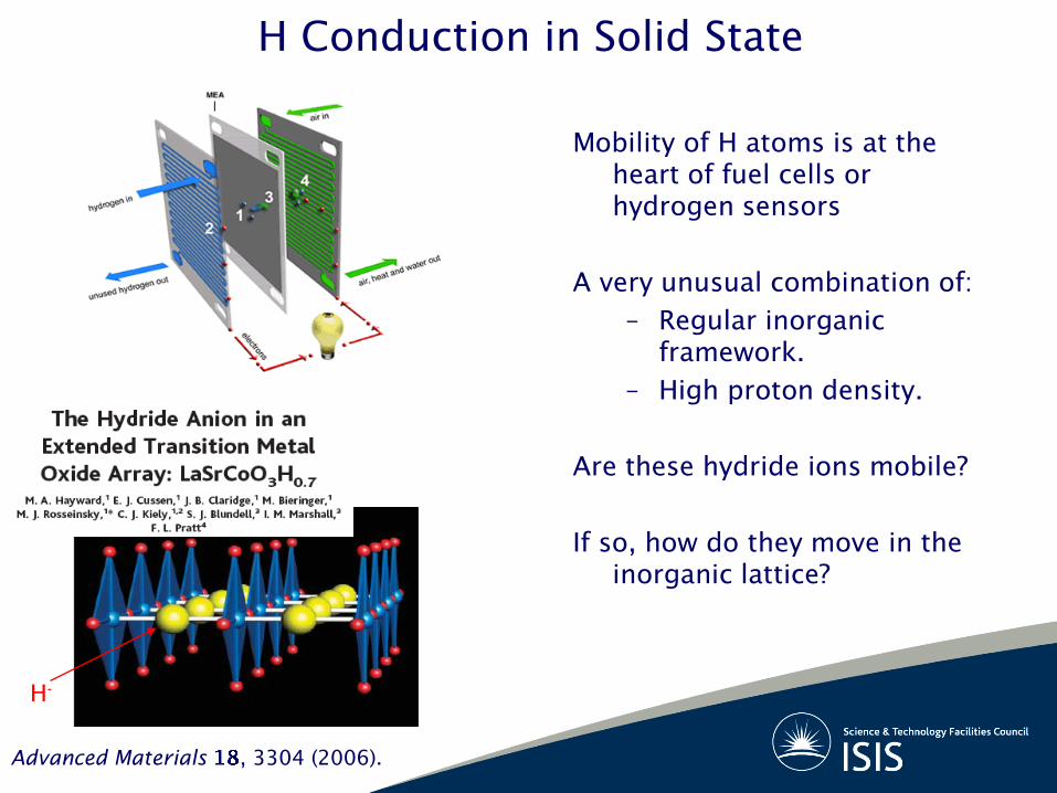
H Conduction in Solid State
Mobility of H atoms is at the
heart of fuel cells or
hydrogen sensors
A very unusual combination of:
– Regular inorganic
framework.
– High proton density.
Are these hydride ions mobile?
If so, how do they move in the
inorganic lattice?
H-
Advanced Materials , 3304 (2006).
-0.4 -0.2 0.0 0.2 0.4
1E-6
1E-5
1E-4
1E-3
0.01
To
tal S
ca
tte
red
In
ten
sity
Energy Transfer [meV]
300K
675K
685K
700K
725K
(a)
0.0 0.2 0.4 0.6 0.8 1.0 1.2 1.4 1.6 1.8 2.0
0.0
0.1
0.2
0.3
0.4
0.5
0.6
0.7 T=685K
Lo
ren
tzia
n F
WH
M [m
eV
]
Q [Å-1]
1.30 1.35 1.40 1.45 1.50
6
9
12
15
D [1
0+
5 c
m2s
-1]
1/T [10+3
K-1]
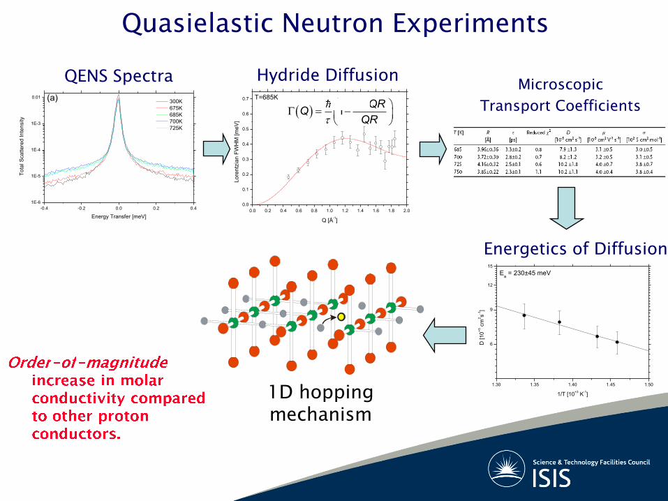
Ea = 230±45 meV
sin
1QR
QQR
1D hopping
mechanism
QENS Spectra Hydride Diffusion
Energetics of Diffusion
Quasielastic Neutron Experiments
Microscopic
Transport Coefficients

Dynamics in the multi-subunit Protein Apoferritin
Iron storage protein
24 peptide chains, hollow,
internal diameter = 80 Å
Shell thickness= 20 Å
simultaneous fit of elastic scattering data
to CH3 jump rotation model
Elastic window scans
IN16
Osiris
res
iommomm gQAppQApprQ
TQS arctan)))]((1(1[2
)))((1(3
exp),0,(22

S. Magazu et al;
Diffusion of Disaccharides
Bioprotectants
J Chem Phys B (2006)
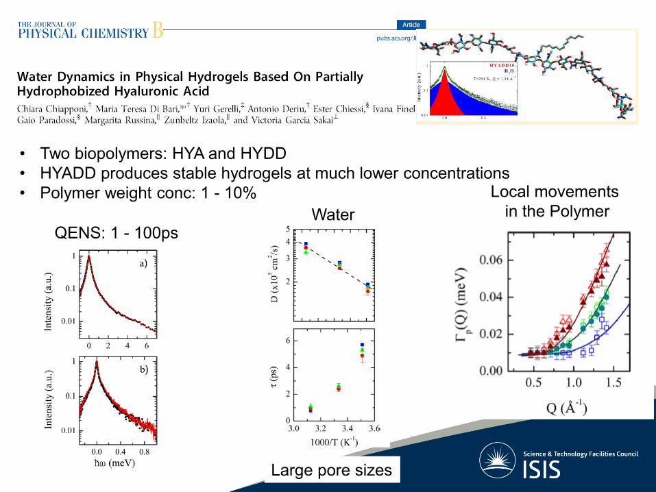
Water
Local movements
in the Polymer
Large pore sizes
• Two biopolymers: HYA and HYDD
• HYADD produces stable hydrogels at much lower concentrations
• Polymer weight conc: 1 - 10%
QENS: 1 - 100ps


Human Blood on IRIS
Red Blood Cells
Haemoglobin
(oxygen carrier)
Volume fraction 25%
RBC = model systems for concentrated protein solutions
Haemoglobin activity is very sensitive
to physiological conditions –
cellular environment resembles a colloidal gel.

Self diffusion of Hb in red blood cells
• Agreement with predictions for hard sphere suspensions
• Hydration shell has to be taken into account
IRIS data

Water diffusion in Human Red Blood Cells
Translational diffusion of water Immobile fraction of water molecules: Bound water in the hydration layer of hemoglobin

Diffusion in liquid Al )(
)(2
2/1QS
QdQDE
“deGennes narrowing”
2 2( )( )
Bk TQ Q
MS Q
Cohen, deSchepper, PRL 1987

How OSIRIS works
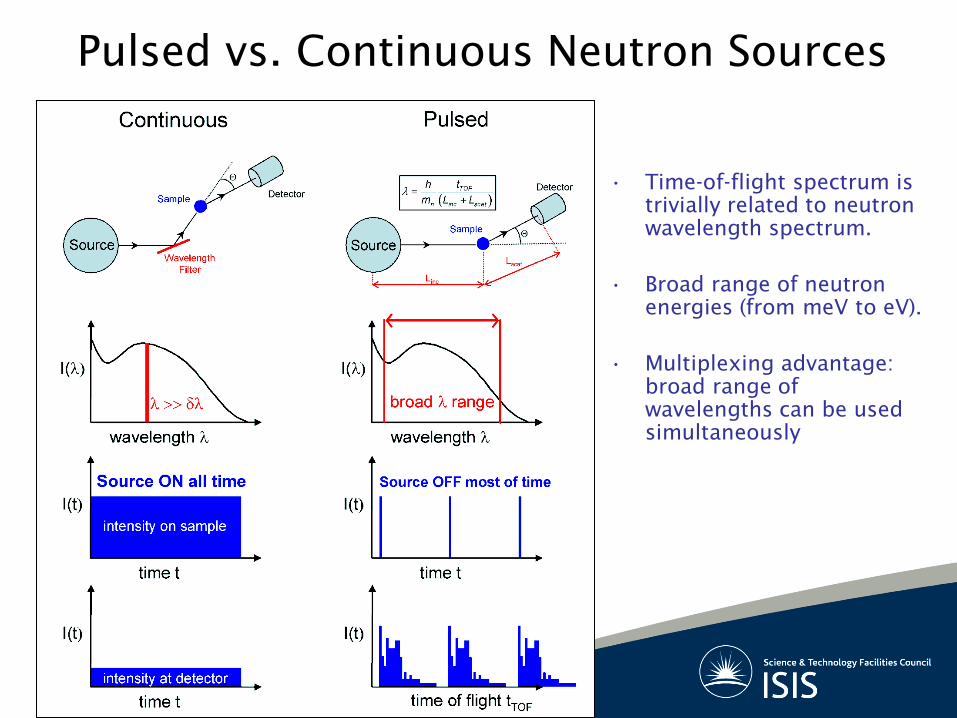
Pulsed vs. Continuous Neutron Sources
• Time-of-flight spectrum is
trivially related to neutron
wavelength spectrum.
• Broad range of neutron
energies (from meV to eV).
• Multiplexing advantage:
broad range of
wavelengths can be used
simultaneously
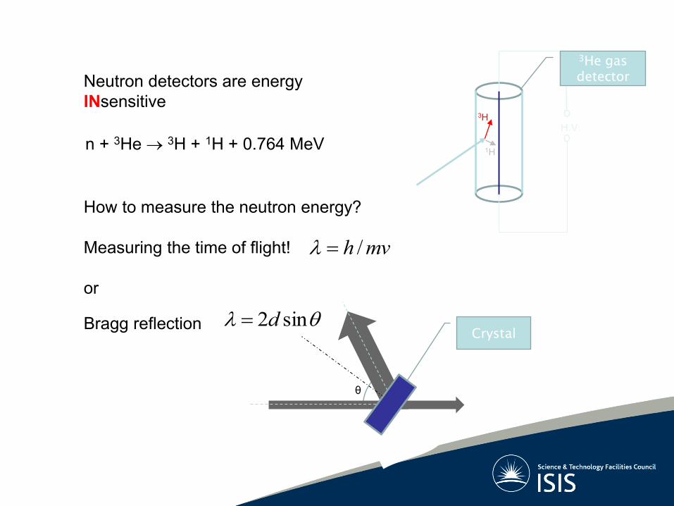
n + 3He 3H + 1H + 0.764 MeV H.V.
3He gas
detector
3H
1H
θ
sin2dCrystal
Bragg reflection
How to measure the neutron energy?
Measuring the time of flight!
or
/h mv
Neutron detectors are energy
INsensitive

Direct Geometry Indirect Geometry
Sample
Chopper
Moderator
Detector
Crystal
Filter
Crystal
Two types of TOF spectrometer
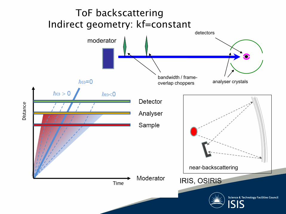
ToF backscattering
Indirect geometry: kf=constant
bandwidth / frame-
overlap choppers
detectors
analyser crystals
near-backscattering
IRIS, OSIRIS
moderator
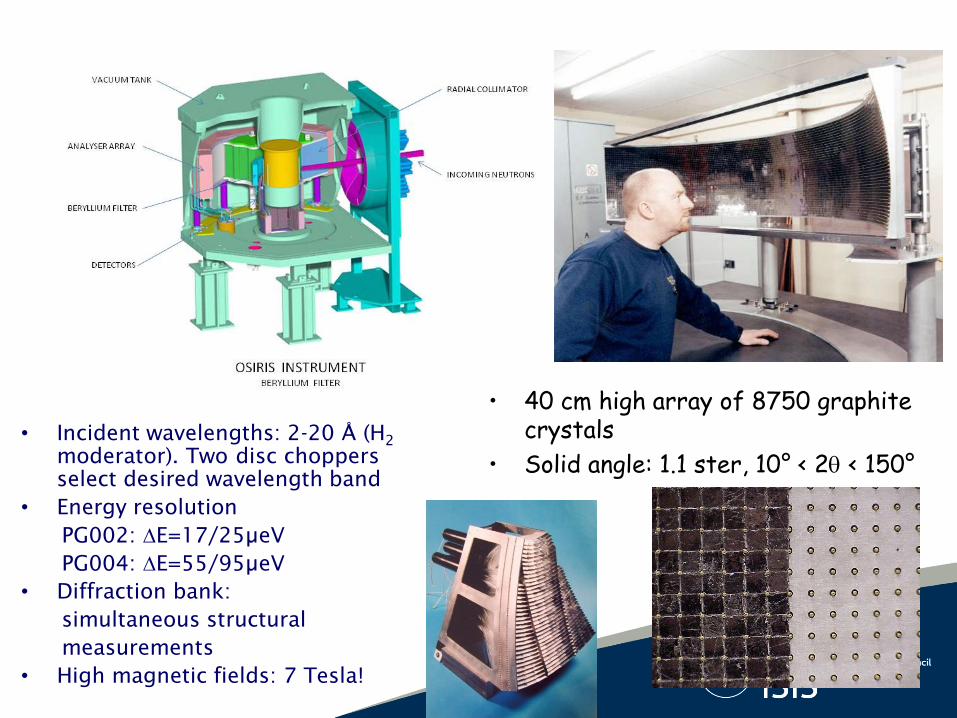
• Incident wavelengths: 2-20 Å (H2
moderator). Two disc choppers
select desired wavelength band
• Energy resolution
PG002: E=17/25µeV
PG004: E=55/95µeV
• Diffraction bank:
simultaneous structural
measurements
• High magnetic fields: 7 Tesla!
• 40 cm high array of 8750 graphite crystals
• Solid angle: 1.1 ster, 10° < 2 < 150°

TDS
Energy Transfer (meV)
-0.4 -0.3 -0.2 -0.1 0.0 0.1 0.2 0.3 0.4
Nor
mal
ised
Inte
nsity
0.00
0.01
0.02
0.03
0.04
0.05
Analyser 8K
Analyser 290K
Energy Transfer (meV)
-0.4 -0.3 -0.2 -0.1 0.0 0.1 0.2 0.3 0.4
Nor
mal
ised
Inte
nsity
0.00
0.01
0.02
0.03
0.04
0.05
Analyser 8K
Analyser 290K

Improving the Energy Resolution: Mica
Fluorophlogopite:
Mica004 not active
Natural Mica – “Muscovite” OH- replaced by F-
Mica006: E=10 µeV
Mica004: E=4.5 µeV
Mica002: E=1 µeV

Energy and Momentum Transfers
kinematic plane
i fE E E
2
22 cosn
inc scat inc scat scat
mQ E E E E
direct
0 2 4 6 8 10 12
-60
-40
-20
0
20
40
60
170o
120o
90o
60o
45o
En
erg
y T
ran
sfe
r [m
eV
]
Momentum Transfer [Å-1]
= 10o
0 2 4 6 8 10 12
-60
-40
-20
0
20
40
60
170o
120o90
o60
o45
o
Momentum Transfer [Å-1]
= 10o
Neutron energy loss
Neutron energy gain
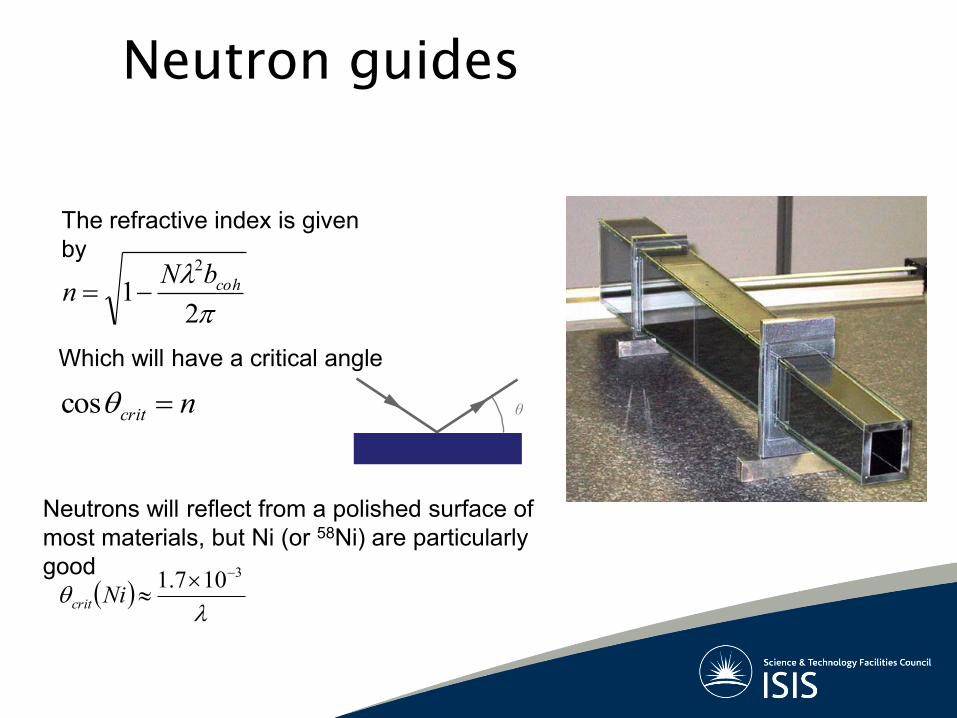
Neutron guides
21
2
cohbNn
ncrit cos
3107.1
Nicrit
The refractive index is given
by
Which will have a critical angle
θ
Neutrons will reflect from a polished surface of
most materials, but Ni (or 58Ni) are particularly
good

Deviation from the Ideal Instrument: Resolution
Two major contributions:
• Timing uncertainties:
– In neutron production for a given wavelength.
– Path differences between source – sample – detector, etc.
• How good your crystal analyser is.
Typically expressed as uncertainties in incident and scattered
energies Einc
and Escat
inc scatE E E Remembering that:
2 2E t
E t
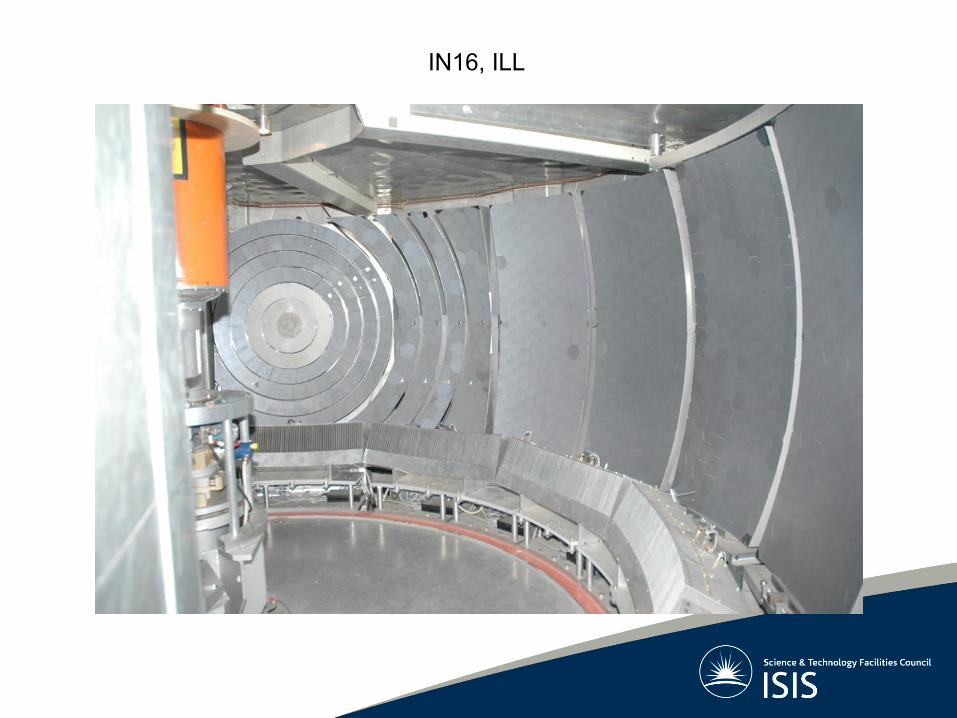
IN16, ILL

How to do a QENS experiment?

2
s, ,4 4
f coh inc
i
kdS S
d d k
Q Q
ki
kf
Ei
Ef
detector
sample
What should we use as a sample?

Hydrogen: A Very Special Case
Isotope substitution!
Contrast variation
1
2
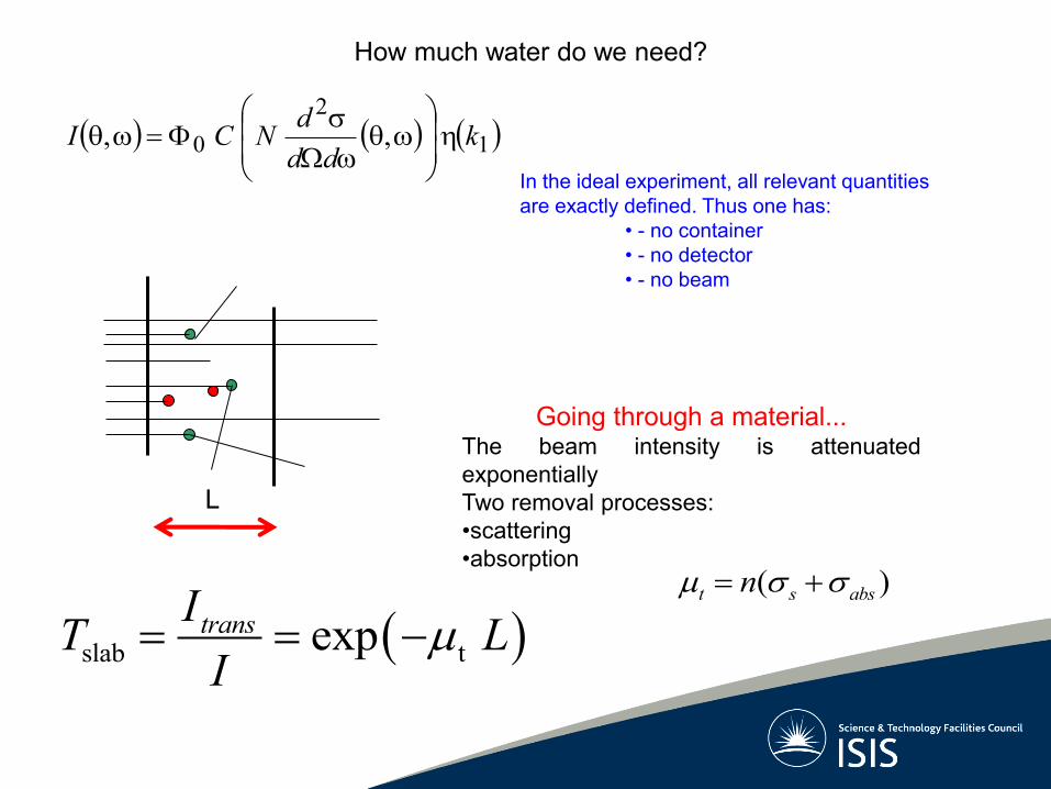
0 ,, kdd
dNCI
In the ideal experiment, all relevant quantities
are exactly defined. Thus one has:
• - no container
• - no detector
• - no beam
Going through a material...
The beam intensity is attenuated
exponentially
Two removal processes:
•scattering
•absorption
slab texptransIT L
I
How much water do we need?
L
( )t s absn

Transmitted fraction for a flat plate geometry:
Try answering the following questions:
• Calculate optimal thickness L to attain a 15% scattered intensity.
• How thick should the plate be for a 10% a 20% and a 50% water sample?
slab texpT L
( )t s absn
ln( )
t
TL
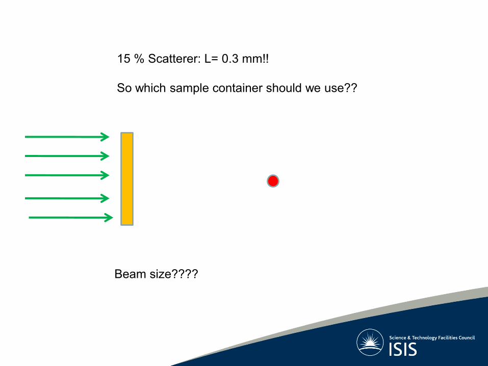
15 % Scatterer: L= 0.3 mm!!
So which sample container should we use??
Beam size????
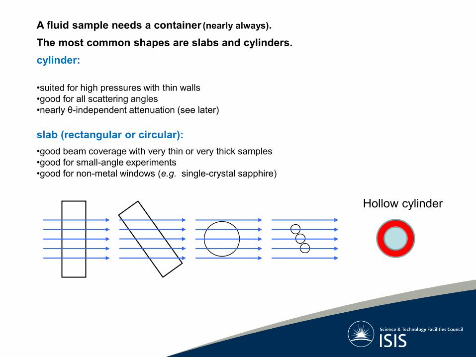
A fluid sample needs a container (nearly always).
The most common shapes are slabs and cylinders.
cylinder:
•suited for high pressures with thin walls
•good for all scattering angles
•nearly θ-independent attenuation (see later)
slab (rectangular or circular):
•good beam coverage with very thin or very thick samples
•good for small-angle experiments
•good for non-metal windows (e.g. single-crystal sapphire)
Hollow cylinder

So what do we really
measure?
I=Isample+Ican+Ibackground+Imultiple scattering +.....
1
2
0 ,, kdd
dNCI

Ñ/degreesA(Ñ)
2 ,
exp-1
2 ,0
20 ,exp
exp-1
0 ,exp
A
θ
Attenuation depends on: θ, even for isotropic scattering
shape and size of sample
property of material(s)
cor
s c s cI I I
Sample +container

rrr stinctexp1
dV
A
Generalizing to any sample shape...
usually referred to as the "As,s Paalman & Pings attenuation coefficient"
astt nn
sm 2200 absorption "1" ; ref
ref
refa
refrefaa
vv
k
kk
,
, , ,
1cor c sc
s c s c
s sc s sc c c
AI I I
A A A

Multiple scattering causes both the loss of "good neutrons" and the
detection of "bad neutrons".
Multiple scattering is an unwanted feature in neutron spectroscopy.
Maximizing the single-scattering intensity is incompatible with
minimizing the multiple-to-single scattering ratio.
Multiple scattering
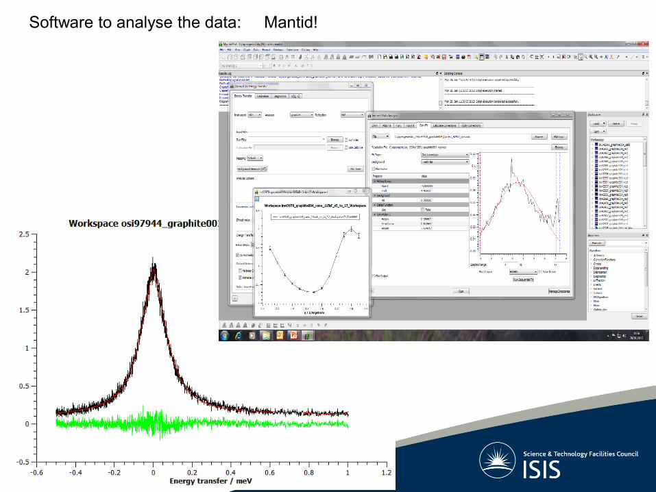
Software to analyse the data: Mantid!
Recommended