1
Manufacturing Tooling 5. Jig Design
Nageswara Rao Posinasetti
February 12, 2008 Nageswara Rao Posinasetti 2
Fixture
A fixture is a means through which a part is securely fastened to the machine tool table to accurately locate, support and hold the part during the machining operation.
February 12, 2008 Nageswara Rao Posinasetti 3
Jig
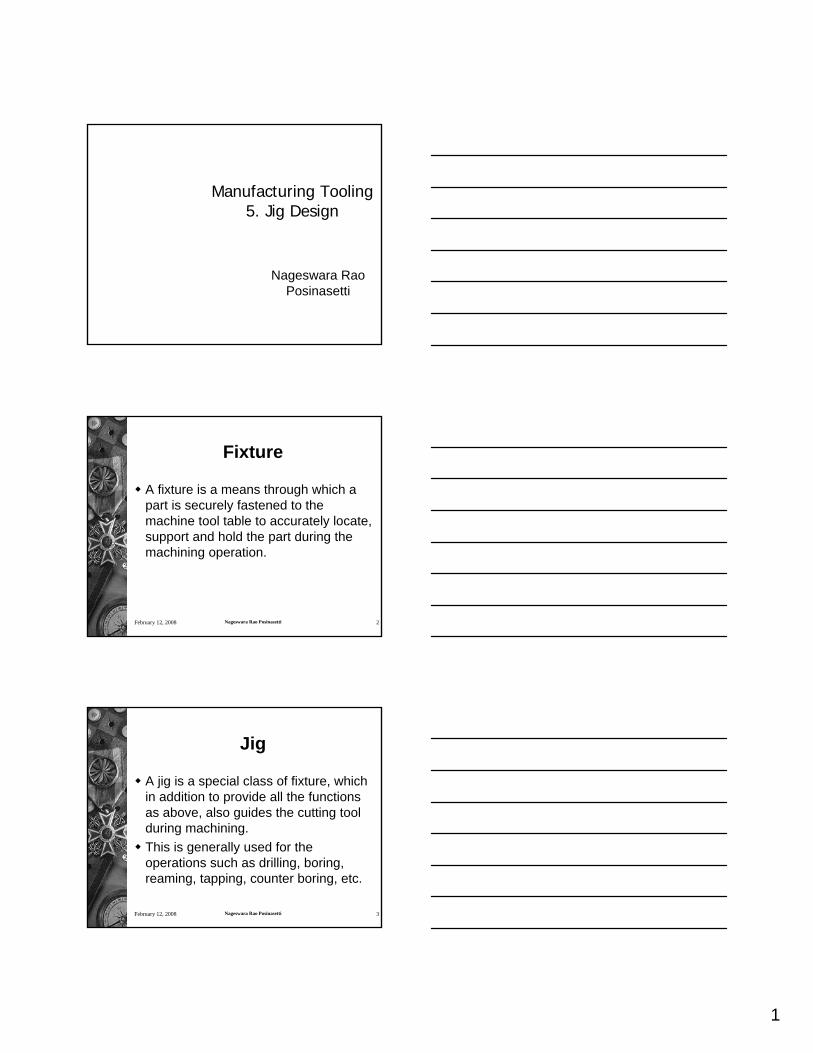
A jig is a special class of fixture, which in addition to provide all the functions as above, also guides the cutting tool during machining. This is generally used for the operations such as drilling, boring, reaming, tapping, counter boring, etc.
2
Typical jig used for boring operation
February 12, 2008 Nageswara Rao Posinasetti 6
3
February 12, 2008 Nageswara Rao Posinasetti 7
Drill Jigs
Provide methods for– Correctly locate the workpiece with
respect to the tool– Securely clamp and rigidly support the
workpiece during the operation– Guide the tool– Position and/or fasten the jig on a
machine
February 12, 2008 Nageswara Rao Posinasetti 8
Drill Jigs
Advantages– Minimize tool breakage– Minimize the possibility of human error– Permit the use of less skilled labor– Reduce manufacturing time– Eliminate retooling for repeat orders
February 12, 2008 Nageswara Rao Posinasetti 9
Machine Considerations
HorsepowerSize limitationsWeight limitationsCutting ToolsSpecial Machinery

4
February 12, 2008 Nageswara Rao Posinasetti 10
Process Considerations
Type of Operations (drilling,reaming, other)Number of Operations – Similar vs. different– Sequential vs. simultaneous
Sequence Inspection Requirements
February 12, 2008 Nageswara Rao Posinasetti 11
Jig Bushes
To position and guide the cutting tool for cutting.Materials– Hardened steel– Carbide– Bronze– Stainless steel
February 12, 2008 Nageswara Rao Posinasetti 12
Headless Bush
Most popular and least expensive
Light axial load is expected

5
February 12, 2008 Nageswara Rao Posinasetti 13
Clearance between Bush and Part
February 12, 2008 Nageswara Rao Posinasetti 14
Headed Drill Bush
Jig plate can be thinner
February 12, 2008 Nageswara Rao Posinasetti 15

6
February 12, 2008 Nageswara Rao Posinasetti 16
February 12, 2008 Nageswara Rao Posinasetti 17
February 12, 2008 Nageswara Rao Posinasetti 18
Slip Renewable Bush
Used for multiple operations such as Drilling followed by reaming

7
February 12, 2008 Nageswara Rao Posinasetti 19
February 12, 2008 Nageswara Rao Posinasetti 20
February 12, 2008 Nageswara Rao Posinasetti 21

8
February 12, 2008 Nageswara Rao Posinasetti 22
February 12, 2008 Nageswara Rao Posinasetti 23
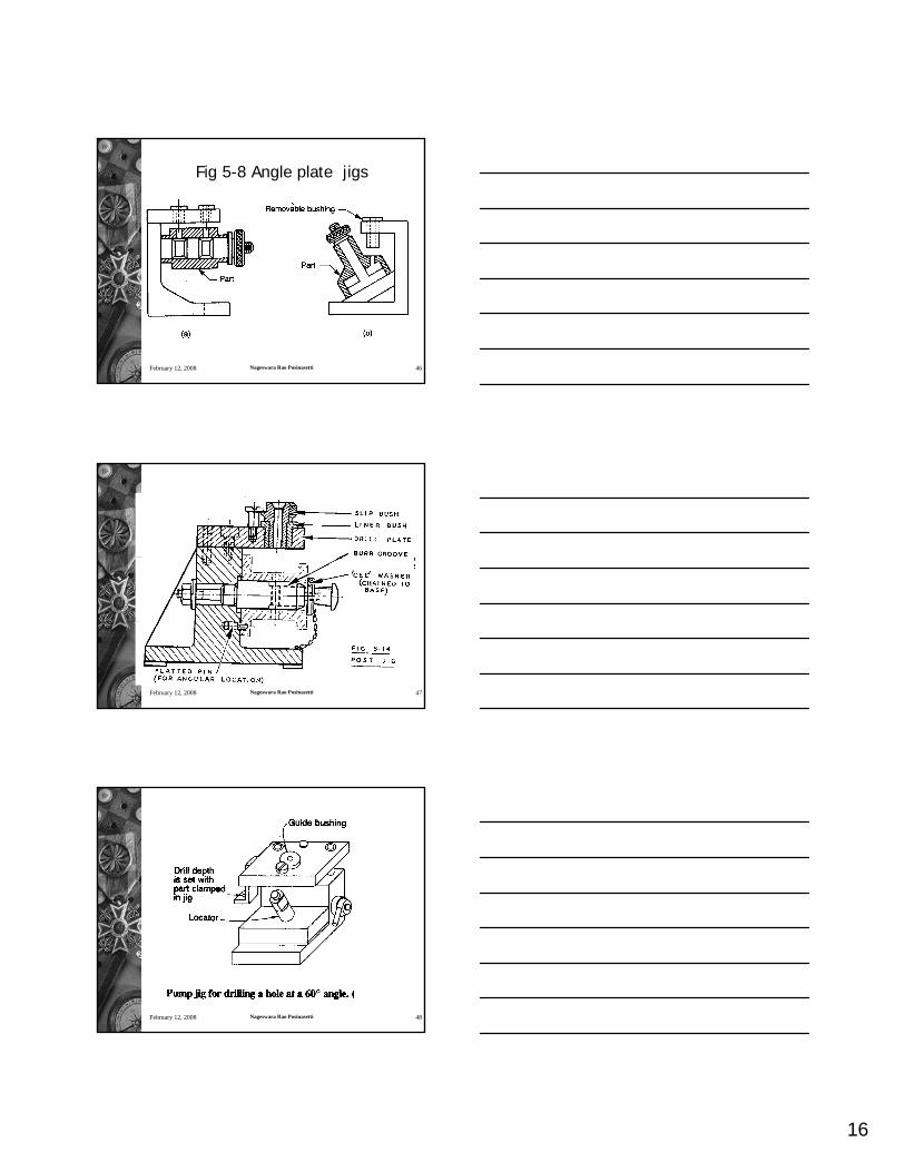
Drill bushing position for angular drill entry
February 12, 2008 Nageswara Rao Posinasetti 24
Fig. 5.43 Drilling irregular work surfaces

9
February 12, 2008 Nageswara Rao Posinasetti 25
February 12, 2008 Nageswara Rao Posinasetti 26
February 12, 2008 Nageswara Rao Posinasetti 27
10
February 12, 2008 Nageswara Rao Posinasetti 28
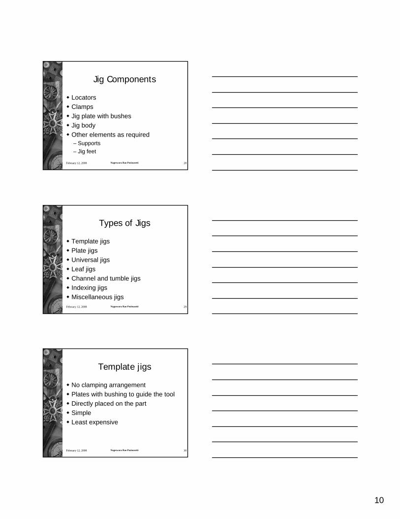
Jig Components
LocatorsClampsJig plate with bushesJig bodyOther elements as required– Supports– Jig feet
February 12, 2008 Nageswara Rao Posinasetti 29
Types of Jigs
Template jigsPlate jigsUniversal jigsLeaf jigsChannel and tumble jigsIndexing jigsMiscellaneous jigs
February 12, 2008 Nageswara Rao Posinasetti 30
Template jigs
No clamping arrangementPlates with bushing to guide the toolDirectly placed on the partSimpleLeast expensive

11
February 12, 2008 Nageswara Rao Posinasetti 31
Nesting Template Drill Jigs
February 12, 2008 Nageswara Rao Posinasetti 32
February 12, 2008 Nageswara Rao Posinasetti 33
Template jigs
Disadvantages– Not as foolproof as other types– Orientation of the hole pattern to
workpiece datums may not be as accurate as other types
– They are usually not practical when locating datums are dimensioned

12
February 12, 2008 Nageswara Rao Posinasetti 34
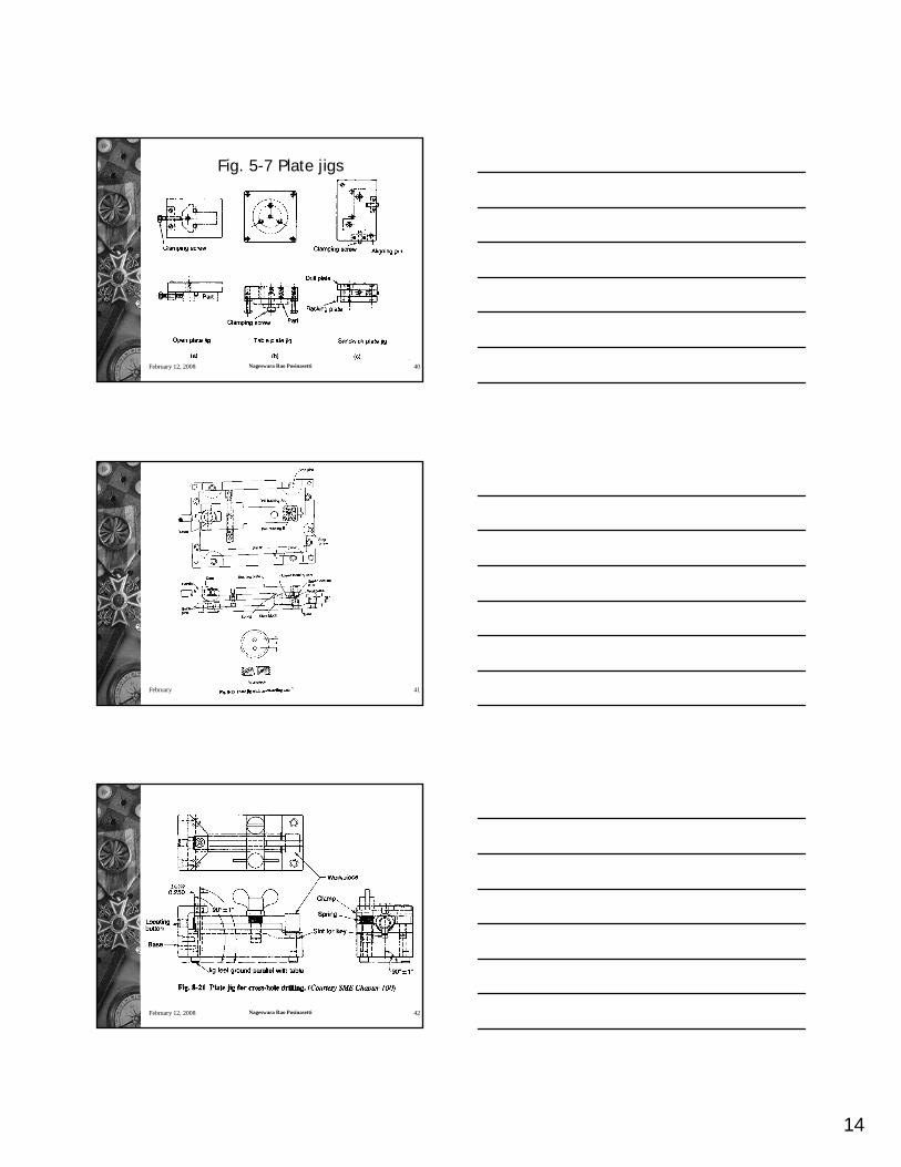
Plate jigs
A template jig with workpiece clamping system
February 12, 2008 Nageswara Rao Posinasetti 35
Plate Jig
February 12, 2008 Nageswara Rao Posinasetti 36
Plate Drill Jig

13
February 12, 2008 Nageswara Rao Posinasetti 37
February 12, 2008 Nageswara Rao Posinasetti 38
Fig. 5-7 Plate jigs
February 12, 2008 Nageswara Rao Posinasetti 39
Fig. 5-7 Plate jigs
14
February 12, 2008 Nageswara Rao Posinasetti 40
Fig. 5-7 Plate jigs
February 12, 2008 Nageswara Rao Posinasetti 41
February 12, 2008 Nageswara Rao Posinasetti 42

15
February 12, 2008 Nageswara Rao Posinasetti 43
February 12, 2008 Nageswara Rao Posinasetti 44
February 12, 2008 Nageswara Rao Posinasetti 45
Fig 5-8 Angle plate jigs
16
February 12, 2008 Nageswara Rao Posinasetti 46
Fig 5-8 Angle plate jigs
February 12, 2008 Nageswara Rao Posinasetti 47
February 12, 2008 Nageswara Rao Posinasetti 48

17
February 12, 2008 Nageswara Rao Posinasetti 49
February 12, 2008 Nageswara Rao Posinasetti 50
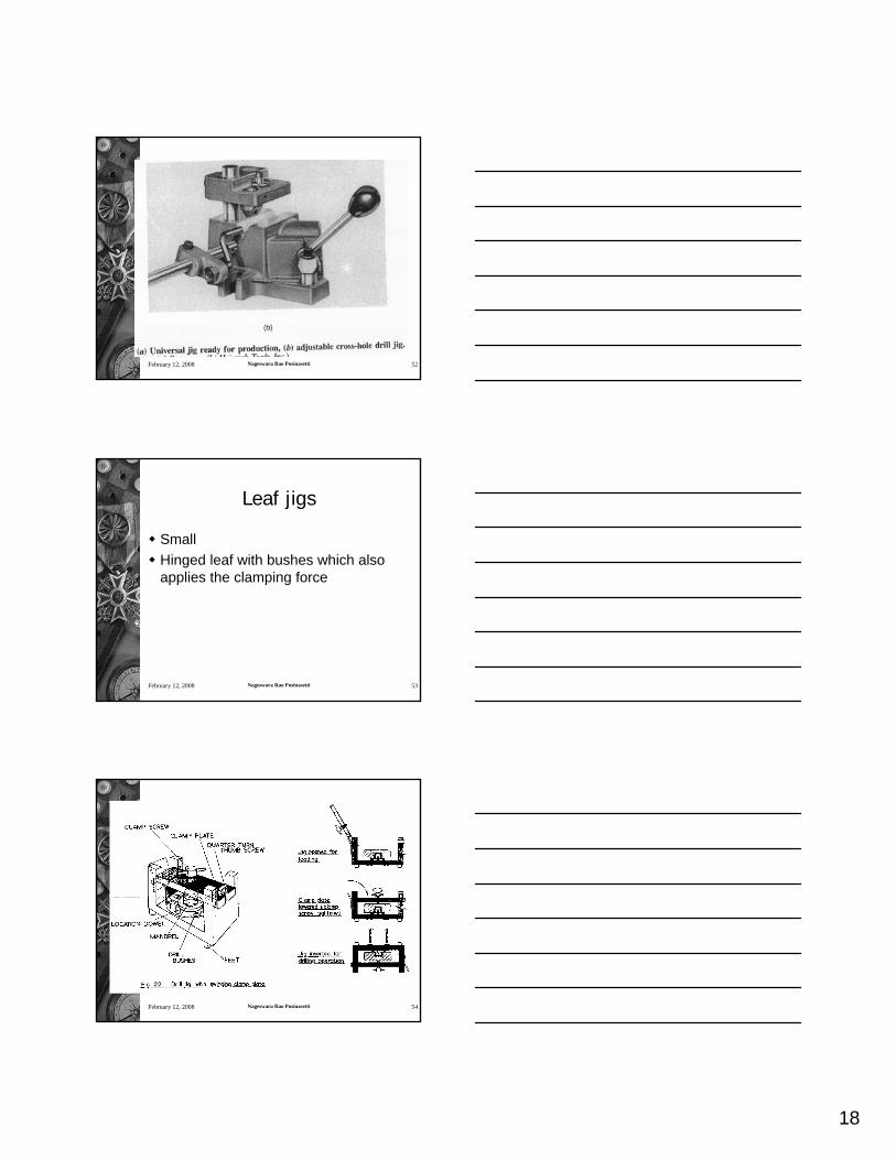
Universal jigs
Also called as Pump jigsUniversal that can be used for any given part by adding the necessary locators and bushes
February 12, 2008 Nageswara Rao Posinasetti 51
18
February 12, 2008 Nageswara Rao Posinasetti 52
February 12, 2008 Nageswara Rao Posinasetti 53
Leaf jigs
SmallHinged leaf with bushes which also applies the clamping force
February 12, 2008 Nageswara Rao Posinasetti 54

19
February 12, 2008 Nageswara Rao Posinasetti 55
February 12, 2008 Nageswara Rao Posinasetti 56
February 12, 2008 Nageswara Rao Posinasetti 57

20
February 12, 2008 Nageswara Rao Posinasetti 58
February 12, 2008 Nageswara Rao Posinasetti 59
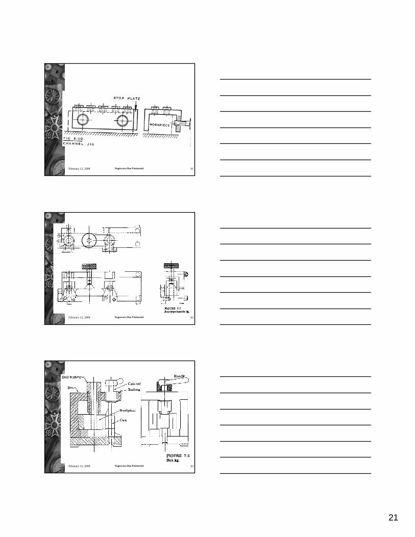
Channel and tumble jigs
For drilling in more than one surfaceComplicated and expensive
February 12, 2008 Nageswara Rao Posinasetti 60
21
February 12, 2008 Nageswara Rao Posinasetti 61
February 12, 2008 Nageswara Rao Posinasetti 62
February 12, 2008 Nageswara Rao Posinasetti 63
22
February 12, 2008 Nageswara Rao Posinasetti 64
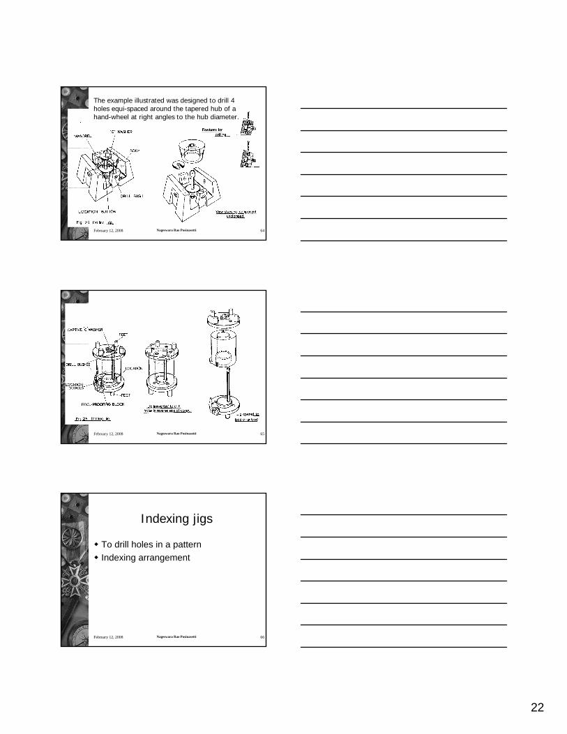
The example illustrated was designed to drill 4 holes equi-spaced around the tapered hub of a hand-wheel at right angles to the hub diameter.
February 12, 2008 Nageswara Rao Posinasetti 65
February 12, 2008 Nageswara Rao Posinasetti 66
Indexing jigs
To drill holes in a patternIndexing arrangement

23
February 12, 2008 Nageswara Rao Posinasetti 67
February 12, 2008 Nageswara Rao Posinasetti 68
February 12, 2008 Nageswara Rao Posinasetti 69

24
February 12, 2008 Nageswara Rao Posinasetti 70
Miscellaneous jigs
February 12, 2008 Nageswara Rao Posinasetti 71
February 12, 2008 Nageswara Rao Posinasetti 72

25
February 12, 2008 Nageswara Rao Posinasetti 73
February 12, 2008 Nageswara Rao Posinasetti 74
Drill Jig with R H Component
February 12, 2008 Nageswara Rao Posinasetti 75
Drill Jig with L H Component

26
February 12, 2008 Nageswara Rao Posinasetti 76
Drill Jig with R H Component unassembled
February 12, 2008 Nageswara Rao Posinasetti 77
Drill Jig with R H and L H Components simultaneously
February 12, 2008 Nageswara Rao Posinasetti 78

27
February 12, 2008 Nageswara Rao Posinasetti 79
Pot Drill Jig
February 12, 2008 Nageswara Rao Posinasetti 80
Pot Drill Jig
February 12, 2008 Nageswara Rao Posinasetti 81

28
February 12, 2008 Nageswara Rao Posinasetti 82
February 12, 2008 Nageswara Rao Posinasetti 83
February 12, 2008 Nageswara Rao Posinasetti 84

29
February 12, 2008 Nageswara Rao Posinasetti 85
Jig Design Guidelines
Drill Jigs should be of light construction, consistent with rigidity to facilitate handling, especially when jigs have to be turned over so that holes can be drilled from more than one side. All unnecessary metal should be cored out of the jig body.
February 12, 2008 Nageswara Rao Posinasetti 86
Jig Design Guidelines
A jig which is not bolted to the machine table should be provided with feet, preferably four, opposite all surfaces containing guide bushings, so that it will 'rock' if not standing square on the table and so warn the operator. Clearance holes or burr slots should be provided in the jig to allow for the burr formed when the drill breaks through the component and for swarf clearance, particularly from locating faces.
February 12, 2008 Nageswara Rao Posinasetti 87
Jig Design Guidelines
Make all component clamping devices as quick acting as possible. Design the jig fool-proof by the use of foul pins and similar devices, that is arrange it so that the component, tools or bushes cannot be inserted except in the correct way. Make some locating points adjustable when the component is a rough casting and may be out of alignment.

30
February 12, 2008 Nageswara Rao Posinasetti 88
Jig Design Guidelines
Locate clamps so that they will be in the best position to resist the pressure of the cutting tool when at work.If possible, make all clamps integral parts of the jig and avoid the use of loose parts. Avoid complicated clamping and locating arrangements which are liable to wear or need constant attention.
February 12, 2008 Nageswara Rao Posinasetti 89
Jig Design Guidelines
Place all clamps as nearly as possible opposite some bearing point of the component to avoid springing the component and in accessible positions. All sharp edges should be removed from the various detail parts of the jig. Provide handles or other devices wherever these will make the handling of the jig more convenient.
February 12, 2008 Nageswara Rao Posinasetti 90
Jig Design Guidelines
If possible, place all tool guide bushings inside the geometrical figure formed by connecting the points of location of the feet. Make, if possible, all locating points visible to the operator when placing the component in position in the jig so that the component can be seen to be correctly located. The operator should also be able to have an unobstructed view of the clamps.
31
February 12, 2008 Nageswara Rao Posinasetti 91
Jig Design Guidelines
Before using the jig in the machine shop for commercial purposes, test all jigs as soon as they are made. The location points, which are hardened if necessary, are established with considerations to machining operations, if any, to follow and that any mating parts are located from the same datum surface.
February 12, 2008 Nageswara Rao Posinasetti 92
Jig Design Guidelines
Locating and clamping arrangements are designed to reduce idle time to a minimum by using simple clamps which are easy and quick to operate and also operate without damaging the component. Springs should be used whenever possible to elevate the clamps clear of the component whilst being loaded or unloaded.
February 12, 2008 Nageswara Rao Posinasetti 93
Jig Design Guidelines
Clamps should be positioned above the points supporting the component, in order to avoid distortion and should be strong enough to hold the component without bending. Generally clamps should not be relied upon for holding the work against the pressure exerted by the cutting tool.
32
February 12, 2008 Nageswara Rao Posinasetti 94
Jig Design Guidelines
Locating and supporting surfaces should, whenever possible, be renewable. – Such surfaces should be of hard material.
February 12, 2008 Nageswara Rao Posinasetti 95
Jig Design Guidelines
The process of inserting and withdrawing the component from the jig should be as easy as possible. – Ample space should be left between the
jig body and the component for hand movements.
– Some means of ejection should exist to release the component if it sticks in the jig.
February 12, 2008 Nageswara Rao Posinasetti 96
Jig Design Guidelines
The design of the jig must be safe. – Handles or levers should be large enough
to clear adjacent parts so that pinched fingers are avoided.

33
February 12, 2008 Nageswara Rao Posinasetti 97
Jig Design Guidelines
If necessary, make provision for the use of coolant. Position locations at places where there is no flash or burr on the component.
February 12, 2008 Nageswara Rao Posinasetti 98
Jig Design Guidelines
If possible, eliminate spanners by the use of levers. – If spanners have to be used, make one
spanner fit all the clamp operating bolts and nuts.
Consideration should be given at the design stage to the use of standardised jig components.
February 12, 2008 Nageswara Rao Posinasetti 99
Power requirement for Drilling
d = drill diameter, inK, A, B, E - Constants
8.18.0, dfAKMTorque =28.08.02, dEKdfBKTThrust +=

34
February 12, 2008 Nageswara Rao Posinasetti 100
February 12, 2008 Nageswara Rao Posinasetti 101
February 12, 2008 Nageswara Rao Posinasetti 102
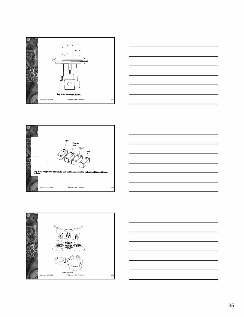
35
February 12, 2008 Nageswara Rao Posinasetti 103
February 12, 2008 Nageswara Rao Posinasetti 104
February 12, 2008 Nageswara Rao Posinasetti 105

36
February 12, 2008 Nageswara Rao Posinasetti 106
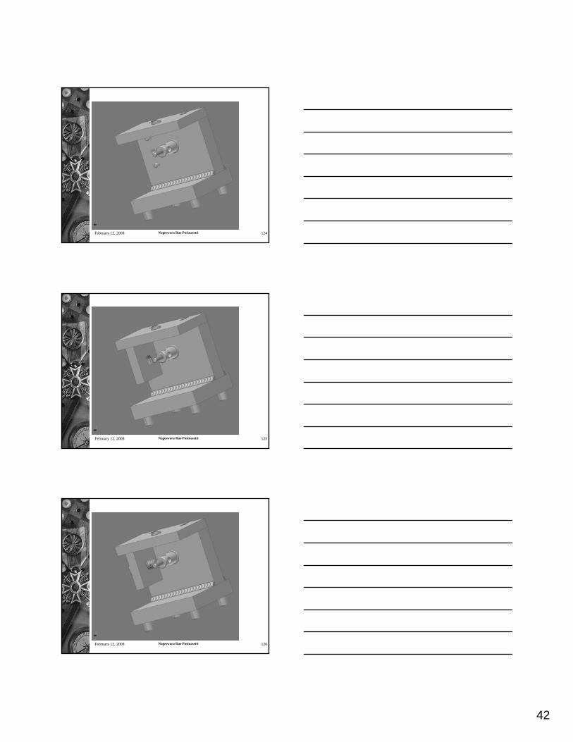
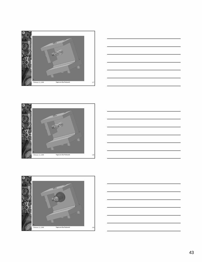
Basic Design Steps
1. Method of locating the part – identify the standard components required for locating purpose.2. Design the clamping method. Make a proper choice of clamps – C-washer, swing washer, nut, strap clamp, toggle clamp, etc.3. Design any supports required4. Design the jig bushes required.5. Design the jig body.
February 12, 2008 Nageswara Rao Posinasetti 107
Design Study – Drill Jig
1. Method of locating the part – The central hole which helps in locating as well as indexing for the hole.2. Clamping can be done with a nut and a C-washerIndexing will have to be done with a plunger type retracting.
February 12, 2008 Nageswara Rao Posinasetti 108
For locating 5/8 in hole
For locating in the jig body

37
February 12, 2008 Nageswara Rao Posinasetti 109
For locating 5/8 in hole
For locating in the jig body
February 12, 2008 Nageswara Rao Posinasetti 110
February 12, 2008 Nageswara Rao Posinasetti 111
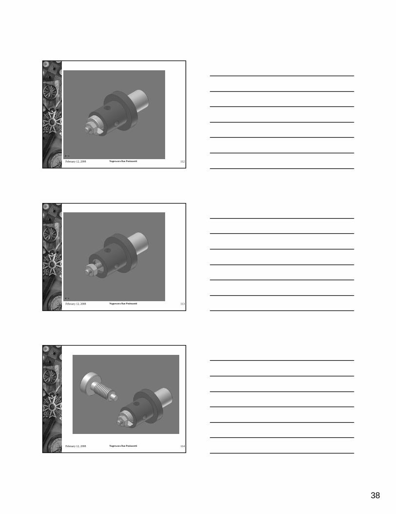
38
February 12, 2008 Nageswara Rao Posinasetti 112
February 12, 2008 Nageswara Rao Posinasetti 113
February 12, 2008 Nageswara Rao Posinasetti 114
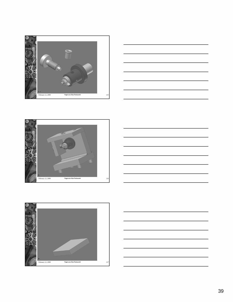
39
February 12, 2008 Nageswara Rao Posinasetti 115
February 12, 2008 Nageswara Rao Posinasetti 116
February 12, 2008 Nageswara Rao Posinasetti 117

40
February 12, 2008 Nageswara Rao Posinasetti 118
February 12, 2008 Nageswara Rao Posinasetti 119
February 12, 2008 Nageswara Rao Posinasetti 120
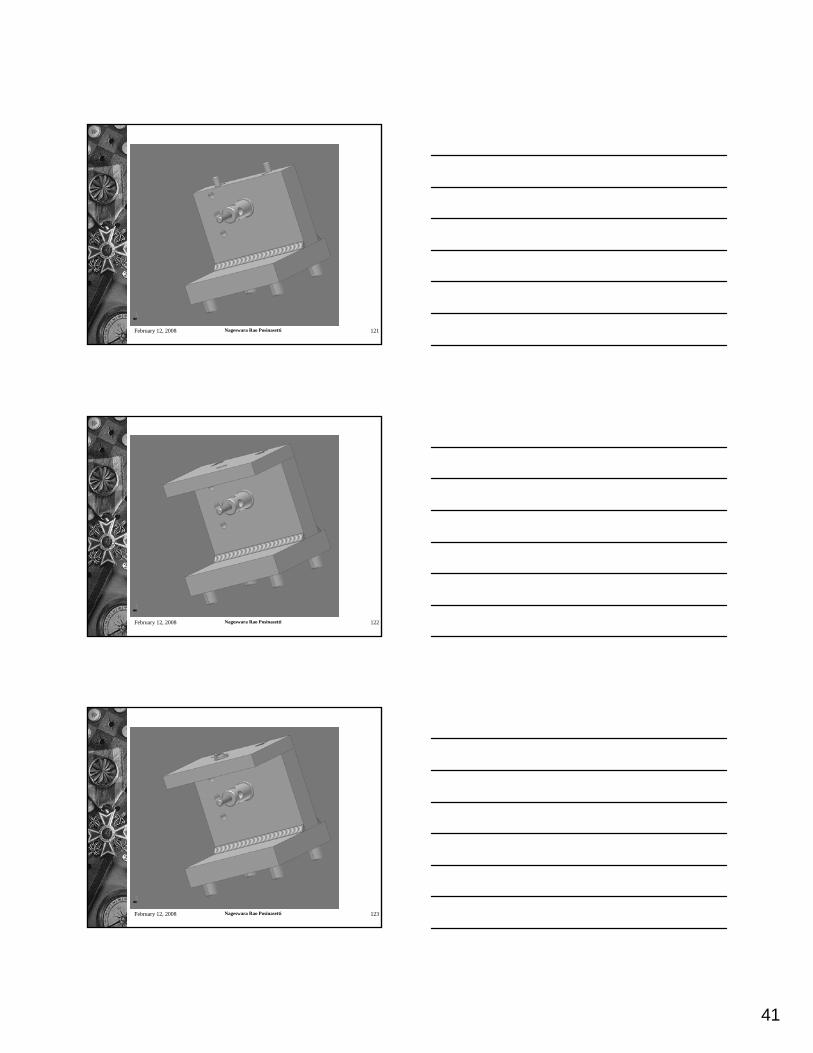
41
February 12, 2008 Nageswara Rao Posinasetti 121
February 12, 2008 Nageswara Rao Posinasetti 122
February 12, 2008 Nageswara Rao Posinasetti 123
42
February 12, 2008 Nageswara Rao Posinasetti 124
February 12, 2008 Nageswara Rao Posinasetti 125
February 12, 2008 Nageswara Rao Posinasetti 126
43
February 12, 2008 Nageswara Rao Posinasetti 127
February 12, 2008 Nageswara Rao Posinasetti 128
February 12, 2008 Nageswara Rao Posinasetti 129
Recommended