RadiocraftsEmbedded Wireless Solutions RC16xxxx-SIG
2016 Radiocrafts AS RC16xxxx-SIG User Manual (rev. 1.9) Page 1 of 17
RC16xxxx-SIG User Manual
Table of contents TABLE OF CONTENTS ............................................................................................................ 1 QUICK START .......................................................................................................................... 2 INTRODUCTION - SIGFOX NETWORK................................................................................... 3 SIGFOX PROTOCOL ................................................................................................................ 4
UART INTERFACE FOR SIGFOX PACKET HANDLING .................................................................. 4 FRAME FORMAT FOR TRANSMITTING DATA .................................................................................. 4 FRAME FORMAT FOR RECEIVING DATA ....................................................................................... 5 UART INTERFACE FOR MODULE CONFIGURATION ...................................................................... 5 UART TIMING INFORMATION ..................................................................................................... 6 POWER MANAGEMENT .............................................................................................................. 9 RSSI READING ........................................................................................................................ 9 TEMPERATURE READING .......................................................................................................... 9 POWER SUPPLY VOLTAGE READING .......................................................................................... 9
HOW TO REGISTER THE DEVICE IN THE SIGFOX BACKEND SYSTEM ......................... 10 MODULE CONFIGURATION .................................................................................................. 11
SIG CONFIGURATION COMMANDS ........................................................................................... 11 SIG CONFIGURATION MEMORY ............................................................................................... 13
APPENDIX 1: ASCII TABLE .................................................................................................. 16 DOCUMENT REVISION HISTORY ......................................................................................... 17 DISCLAIMER .......................................................................................................................... 17 TRADEMARKS ....................................................................................................................... 17 LIFE SUPPORT POLICY ........................................................................................................ 17 CONTACT INFORMATION ..................................................................................................... 17

RadiocraftsEmbedded Wireless Solutions RC16xxxx-SIG
2016 Radiocrafts AS RC16xxxx-SIG User Manual (rev. 1.9) Page 2 of 17
Quick Start How do I transmit data? Send your data to the RXD pin on the module. Use the UART format with settings (19200, 8, 1, N, no flow control). Up to 12 bytes payload are buffered in the module. The first byte of the message must contain the message length (excluding the length byte itself). The module will transmit the data when the whole packet is received. How do I receive data? The module has to be configured to Uplink and downlink mode in order to enable two way communication. Any received RF data packet with correct message format (ID, key, CRC) will be sent on the TXD pin with length byte first. The RSSI value (received signal strength) can optionally be added to the message. What about the antenna? In most cases a simple quarter wavelength wire or a PCB track will do. Connect a piece of wire to the RF pin with length corresponding to the quarter of a wavelength. For space limited products, contact Radiocrafts and we will recommend the best antenna solution for your application. How do I change any configuration parameter? To change configurable parameters, send one byte to the module with the value 0x00 or assert the CONFIG pin. This will take the module into configuration mode. Special commands are then used to access the configuration registers and test modes. Exit from configuration mode by sending the ‘X’ command. Parameters can be changed permanently and stored in non-volatile memory in the module.
RadiocraftsEmbedded Wireless Solutions RC16xxxx-SIG
2016 Radiocrafts AS RC16xxxx-SIG User Manual (rev. 1.9) Page 3 of 17
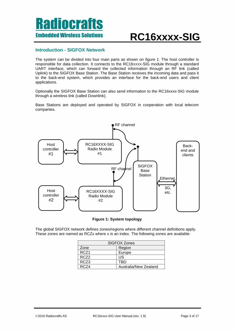
Introduction - SIGFOX Network The system can be divided into four main parts as shown on figure 1. The host controller is responsible for data collection. It connects to the RC16XXXX-SIG module through a standard UART interface, which can forward the collected information through an RF link (called Uplink) to the SIGFOX Base Station. The Base Station receives the incoming data and pass it to the back-end system, which provides an interface for the back-end users and client applications. Optionally the SIGFOX Base Station can also send information to the RC16xxxx-SIG module through a wireless link (called Downlink). Base Stations are deployed and operated by SIGFOX in cooperation with local telecom companies.
Figure 1: System topology
The global SIGFOX network defines zones/regions where different channel definitions apply. These zones are named as RCZx where x is an index. The following zones are available:
SIGFOX Zones
Zone Region
RCZ1 Europe
RCZ2 US
RCZ3 TBD
RCZ4 Australia/New Zealand
Ethernet,
3G, etc.
RC16XXXX-SIG Radio Module
#1
SIGFOX Base
Station
RF channel
RF channel
Back-end and clients
Host controller
#1
RC16XXXX-SIG Radio Module
#2
Host controller
#2
RadiocraftsEmbedded Wireless Solutions RC16xxxx-SIG
2016 Radiocrafts AS RC16xxxx-SIG User Manual (rev. 1.9) Page 4 of 17
SIGFOX protocol Basic functionality The SIGFOX protocol defines two types of network modes:
1. Only uplink mode Packets are only transmitted from the RC16xxxx-SIG module to the base station. This mode can be used for pure data collection.
2. Uplink and downlink mode Packets transmitted by the RC16xxxx-SIG module are acknowledged by the base station. This mode can be used for controlling applications.
The user can select the preferred mode in Configuration mode and tune the parameters (timings, retransmission) accordingly. Public key SIGFOX offers a USB dongle to ease the product development process. This dongle provides a user interface and is able to receive packets using a public ID and KEY pair. The RC16xxxx-SIG module can be configured to use this public parameters and thus is able to connect to the dongle.
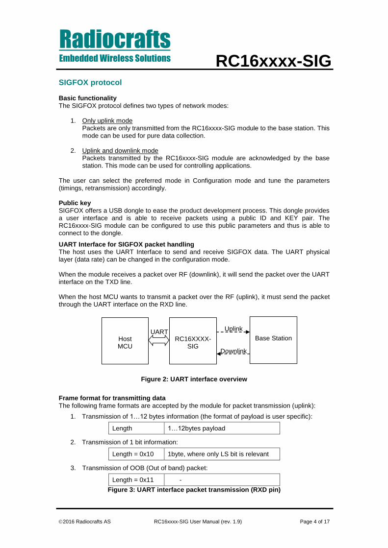
UART Interface for SIGFOX packet handling The host uses the UART Interface to send and receive SIGFOX data. The UART physical layer (data rate) can be changed in the configuration mode. When the module receives a packet over RF (downlink), it will send the packet over the UART interface on the TXD line. When the host MCU wants to transmit a packet over the RF (uplink), it must send the packet through the UART interface on the RXD line.
Figure 2: UART interface overview
Frame format for transmitting data The following frame formats are accepted by the module for packet transmission (uplink):
1. Transmission of 1…12 bytes information (the format of payload is user specific):
Length 1…12bytes payload
2. Transmission of 1 bit information:
Length = 0x10 1byte, where only LS bit is relevant
3. Transmission of OOB (Out of band) packet:
Length = 0x11 -
Figure 3: UART interface packet transmission (RXD pin)
Uplink
Downlink
Host MCU
RC16XXXX-SIG
Base Station UART

RadiocraftsEmbedded Wireless Solutions RC16xxxx-SIG
2016 Radiocrafts AS RC16xxxx-SIG User Manual (rev. 1.9) Page 5 of 17
Out of Band (OOB) packet: A special SIGFOX packet generated by the module and contains information about RSSI, temperature and voltage levels. It can be used for supervision of the module and is automatically generated in Uplink and Downlink mode after every packet received by the RC16xxxx-SIG radio module. Optionally, the user can enable a periodic OOB transmission by setting the configuration parameter ‘0x2F – OOB_PERIOD’ to the required period. The unit then will schedule the packets automatically even if no user data is forwarded. This feature is only available if SLEEP mode is set.
Frame format for receiving data The following packet format is used in case of reception of downlink packet:
Length 8 bytes payload Optional RSSI
Figure 4: UART interface packet reception (TXD pin)
The ‘Length’ byte is calculated over the payload and optional RSSI field only.
UART Interface for Module Configuration
Figure 5: Configuration mode flow diagram The configuration of the module can be changed in-circuit from the host during operation, at the time of installation of the equipment, at the manufacturing test, or even as a stand-alone module. The configuration is changed by sending commands on the UART interface after the module is set in configuration mode. The configuration mode is entered by sending 00h to the module, or by asserting the CONFIG pin (set low). In configuration mode the module will respond by sending a ‘>’ prompt on the TXD pin. This indicates that the module is ready to receive commands. The CONFIG pin (if used) can then be de-asserted. Note that the CONFIG pin must be de-asserted before the Exit command (‘X’) is sent to the module in order to return to normal operation. After a command is executed, the module responds with the ‘>’ prompt character again, indicating it is ready for a new command. Do not send a new command before the ‘>’ prompt is received. The time required to execute a command can vary depending on the command (see the Timing Information section). There is no ‘>’ prompt after the ‘X’ exit command.
RadiocraftsEmbedded Wireless Solutions RC16xxxx-SIG
2016 Radiocrafts AS RC16xxxx-SIG User Manual (rev. 1.9) Page 6 of 17
The parameters that are set by dedicated configuration commands (i.e. ‘F’) take immediate effect after returning to normal operation (IDLE), but will not be stored in non-volatile memory and will be lost in case the supply power is turned off or if the module is reset. Permanent changes of parameters can be done by writing to the configuration memory using the memory command ‘M’. These are for example default RSSI append, default LED control, etc, See the Configuration Memory section for details. The flow diagram above illustrates how to use the UART interface to enter configuration mode, change configuration parameters and return to IDLE mode.
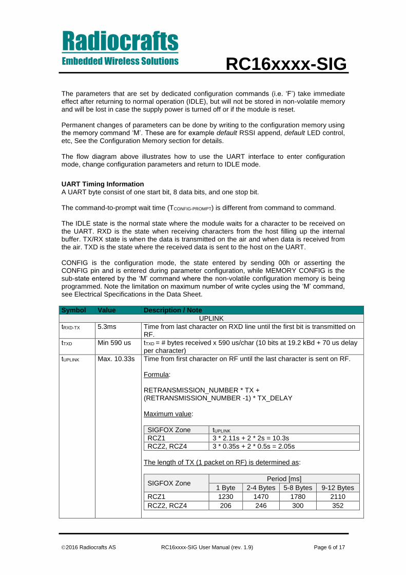
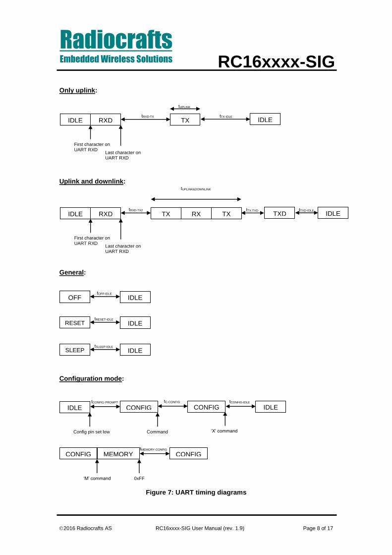
UART Timing Information A UART byte consist of one start bit, 8 data bits, and one stop bit. The command-to-prompt wait time (TCONFIG-PROMPT) is different from command to command. The IDLE state is the normal state where the module waits for a character to be received on the UART. RXD is the state when receiving characters from the host filling up the internal buffer. TX/RX state is when the data is transmitted on the air and when data is received from the air. TXD is the state where the received data is sent to the host on the UART. CONFIG is the configuration mode, the state entered by sending 00h or asserting the CONFIG pin and is entered during parameter configuration, while MEMORY CONFIG is the sub-state entered by the ‘M’ command where the non-volatile configuration memory is being programmed. Note the limitation on maximum number of write cycles using the ‘M’ command, see Electrical Specifications in the Data Sheet.
Symbol Value Description / Note
UPLINK
tRXD-TX
5.3ms Time from last character on RXD line until the first bit is transmitted on RF.
tTXD Min 590 us tTXD = # bytes received x 590 us/char (10 bits at 19.2 kBd + 70 us delay per character)
tUPLINK Max. 10.33s Time from first character on RF until the last character is sent on RF. Formula: RETRANSMISSION_NUMBER * TX + (RETRANSMISSION_NUMBER -1) * TX_DELAY Maximum value:
SIGFOX Zone tUPLINK
RCZ1 3 * 2.11s + 2 * 2s = 10.3s
RCZ2, RCZ4 3 * 0.35s + 2 * 0.5s = 2.05s
The length of TX (1 packet on RF) is determined as:
SIGFOX Zone Period [ms]
1 Byte 2-4 Bytes 5-8 Bytes 9-12 Bytes
RCZ1 1230 1470 1780 2110
RCZ2, RCZ4 206 246 300 352

RadiocraftsEmbedded Wireless Solutions RC16xxxx-SIG
2016 Radiocrafts AS RC16xxxx-SIG User Manual (rev. 1.9) Page 7 of 17
tTX-IDLE 0…2s Time from last character is sent on RF until the module is in IDLE mode (ready for RXD). In only uplink mode, it is equivalent to TX_DELAY.
UPLINK & DOWNLINK
tRXD-TX2 5.3ms Time from last character on RXD line until the first bit is transmitted on RF.
tUPLINK&DO
WLINK Max. 50.72s Time from first character transmitted on RF until the last bit is sent on
RF. Formula: TX + WAIT + RX_WINDOW + OOB_DELAY + OOB Maximum value:
SIGFOX Zone TMAX
RCZ1 2.11s + 20s + 25s + 1.5s + 2.11s = 50.72s
RCZ2, RCZ4 0.35s + 20s + 25s + 1.5s + 0.35s = 47.2s
tTX-TXD 512ms Time from last character is sent on the air until module is in IDLE mode.
tTXD-IDLE 1.1ms Time from the last character sent on TXD until the module is in IDLE mode.
GENERAL
tOFF-IDLE 13.2ms Time from voltage is stabilized until the module is ready to receive on RXD pin.
tRESET-IDLE 13.2ms Time from the rising edge of reset pin until the module is ready to receive on RXD pin.
tSLEEP-IDLE 1.8ms Time from the falling edge of RXD pin until the module is ready to receive the first (length) byte.
CONFIGURATION MODE
tCONFIG-
PROMPT
86us Time from the edge of config pin until the start bit of prompt.
tC-CONFIG 80us Time from the last byte is sent until the prompt.
tCONFIG-IDLE 1ms Time from the ‘X’ command is sent until the module is in IDLE mode.
tMEMORY-
CONFIG
31ms Time from the end character 0xFF until the prompt is issued.
*SIGFOX Zones: RCZ1 (Europe), RCZ2 (US), RCZ4 (AU/NZ)
RadiocraftsEmbedded Wireless Solutions RC16xxxx-SIG
2016 Radiocrafts AS RC16xxxx-SIG User Manual (rev. 1.9) Page 8 of 17
Only uplink: Uplink and downlink: General: Configuration mode: v
Figure 7: UART timing diagrams
TX IDLE IDLE RXD
First character on UART RXD
Last character on UART RXD
tRXD-TX tTX-IDLE
TX RX TX TXD IDLE IDLE RXD
First character on UART RXD
Last character on UART RXD
tRXD-TX2 tTX-TXD tTXD-IDLE
tUPLINK&DOWNLINK
tUPLINK
IDLE RESET
t
tRESET-IDLE
IDLE SLEEP tSLEEP-IDLE
IDLE
Config pin set low
CONFIG tCONFIG-PROMPT
CONFIG tC-CONFIG tCONFIG-IDLE
IDLE
Command ‘X’ command
CONFIG
‘M’ command
CONFIG tMEMORY-CONFIG
0xFF
IDLE OFF tOFF-IDLE
MEMORY

RadiocraftsEmbedded Wireless Solutions RC16xxxx-SIG
2016 Radiocrafts AS RC16xxxx-SIG User Manual (rev. 1.9) Page 9 of 17
Power Management The module can be set in SLEEP mode in order to reduce the power consumption. The low power SLEEP mode is manually entered by using the SLEEP command ‘Z’ after the module is set in configuration mode. It is also possible to configure the module to enter SLEEP automatically after a message has been transmitted (SLEEP_MODE=1). With this setup the module has to enter TX-mode (transmit a message) after power-on before entering SLEEP mode first time. In SLEEP mode the module will not receive or detect incoming data, neither from the host (UART port) nor from the air. The module is awakened from the SLEEP mode by sending the wake-up byte FFh on the UART RXD line (use a UART Baud rate > 4.8 kBd due to a maximum pulse length requirement). After the module has woken up (see Timing Information) it is ready to receive data on the UART. All configuration settings and RAM values are retained during SLEEP. If the module is shut completely off (supply power turned off), all configuration settings in non-volatile memory is restored, but values in RAM are overwritten with default settings.
RSSI Reading The module provide a digital Received Signal Strength Indicator (RSSI) through the ‘S’ command, or attached to the received messages. The RSSI value appended to a received message is the signal strength of that received packet. The RSSI value is an 8 bit character (one byte) indicating the current input signal strength or the signal strength of the received message. The signal strength can be used as an indication of fading margin, or as a carrier sense signal to avoid collisions. The RSSI value increases with increased input signal strength in 0.5 dB steps. Input signal strength is given by (typ.): P = - RSSI / 2 [dBm]
Temperature Reading The module provides readings of a digital temperature monitoring sensor (TEMP) through the ‘U’ command. The module returns an 8 bit character (one byte) indicating the current temperature in degrees Celsius (°C) followed immediately by a second character which is the prompt (‘>’). The TEMP value increases with increased temperature in 1 °C steps and has an accuracy of +/- 2 °C. The temperature is given by: T = TEMP(dec) - 128 [°C] (example: TEMP=0x98 equals +24 °C)
Power Supply voltage Reading The module provides readings of an internal power supply voltage monitoring sensor (VCC) through the ‘V’ command. The module returns an 8 bit character (one byte) indicating the current power supply voltage level followed immediately by a second character which is the prompt (‘>’). The command can be useful for battery power monitoring. The VCC value increases with increased supply voltage in 30 mV/step. The power supply voltage is given by: V = VCC(dec)*0.030 [V] (example: VCC=0x68 equals 3.12 V)

RadiocraftsEmbedded Wireless Solutions RC16xxxx-SIG
2016 Radiocrafts AS RC16xxxx-SIG User Manual (rev. 1.9) Page 10 of 17
How to register the device in the SIGFOX backend system To be able to register the final product in the backend system of SIGFOX, the device ID and PAC number has to be delivered to the customer with the final product. Radiocrafts programs each device with the correspondent ID and PAC in configuration memory. It is the responsibility of product manufacturer to extract these information and forward them to the final customer i.e. to print the ID and PAC onto the label of product. The exact procedure of registration on the SIGFOX network is described in RC16xxxx-SIG-DK_Quick_Start document.
RadiocraftsEmbedded Wireless Solutions RC16xxxx-SIG
2016 Radiocrafts AS RC16xxxx-SIG User Manual (rev. 1.9) Page 11 of 17
Module configuration
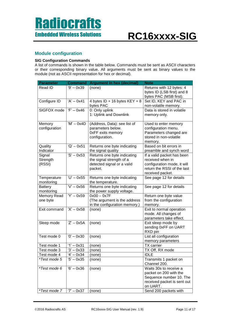
SIG Configuration Commands A list of commands is shown in the table below. Commands must be sent as ASCII characters or their corresponding binary value. All arguments must be sent as binary values to the module (not as ASCII representation for hex or decimal).
Parameter Command Argument in hex (decimal) Note
Read ID ‘9’ – 0x39 (none) Returns with 12 bytes: 4 bytes ID (LSB first) and 8 bytes PAC (MSB first).
Configure ID ‘A’ – 0x41 4 bytes ID + 16 bytes KEY + 8 bytes PAC
Set ID, KEY and PAC in non-volatile memory.
SIGFOX mode ‘F’ – 0x46 0: Only uplink 1: Uplink and Downlink
Data is stored in volatile memory only.
Memory configuration
‘M’ – 0x4D (Address, Data): see list of parameters below. 0xFF exits memory configuration.
Used to enter memory configuration menu. Parameters changed are stored in non-volatile memory.
Quality Indicator
‘Q’ – 0x51 Returns one byte indicating the signal quality
Based on bit errors in preamble and synch word
Signal Strength (RSSI)
‘S’ – 0x53 Returns one byte indicating the signal strength of a detected signal or a valid packet.
If a valid packet has been received when in configuration mode, it will return the RSSI of the last received packet.
Temperature monitoring
‘U’ – 0x55 Returns one byte indicating the temperature.
See page 12 for details
Battery monitoring
‘V’ – 0x56 Returns one byte indicating the power supply voltage.
See page 12 for details
Memory Read one byte
‘Y’ – 0x59 0x00 – 0x7F (The argument is the address in the configuration memory.)
Return one byte value from the configuration memory.
Exit command ‘X’ – 0x58 (none) Exit to normal operation mode. All changes of parameters take effect.
Sleep mode ‘Z’ – 0x5A (none) Exit sleep mode by sending 0xFF on UART RXD pin
Test mode 0 ‘0’ – 0x30 (none) List all configuration memory parameters
Test mode 1 ‘1’ – 0x31 (none) TX carrier
Test mode 3 ‘3’ – 0x33 (none) TX Off, RX mode
Test mode 4 ‘4’ – 0x34 (none) IDLE
*Test mode 5 ‘5’ – 0x35 (none) Transmits 1 packet on Channel 200.
*Test mode 6 ‘6’ – 0x36 (none) Waits 30s to receive a packet on 200 with the Sequence number 10. The received packet is sent out on UART.
*Test mode 7 ‘7’ – 0x37 (none) Send 200 packets with

RadiocraftsEmbedded Wireless Solutions RC16xxxx-SIG
2016 Radiocrafts AS RC16xxxx-SIG User Manual (rev. 1.9) Page 12 of 17
frequency hopping.
**Test mode 7 ‘7’ – 0x37 Arg_0, Arg_1 SIGFOX_API_test_mode (Arg_0, Arg_1)
Test mode 8 ‘8’ – 0x38 (none) Verify EEPROM.
*Available on RC1682-SIG only. **Available on RC1692HP-SIG only. Note: ASCII characters are written as ‘X’, hexadecimal numbers are written like 0x00, and decimal numbers are written like 10 throughout the text. A table of ASCII characters and their respective hex and decimal values are found in the Appendix. Any invalid command will be ignored and the ‘>’ prompt will be re-sent. If Test mode 1 or 2 is used, it is important to enter Test mode 3 before exiting the configuration mode (‘X’) in order to ensure proper operation in normal mode. Example: To change the SIGFOX mode to Uplink and Downlink, use the following sequence: Command Hex Response Comment/Note Enter 0x00 ‘>’ Or assert CONFIG pin
De-assert CONFIG after ‘>’ prompt ‘F’ 0x46 ‘>’
1 0x01 ‘>’ Wait for ‘>’ prompt [A new command could be issued here] ‘X’ 0x58 (none) Module returns to IDLE state
Note that the CONFIG line must be de-asserted after the first ‘>’ prompt was received, but before the ‘X’ command.
RadiocraftsEmbedded Wireless Solutions RC16xxxx-SIG
2016 Radiocrafts AS RC16xxxx-SIG User Manual (rev. 1.9) Page 13 of 17
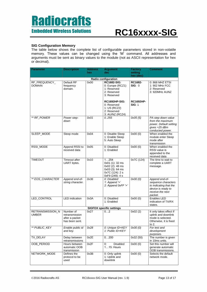
SIG Configuration Memory The table below shows the complete list of configurable parameters stored in non-volatile memory. These values can be changed using the ‘M’ command. All addresses and arguments must be sent as binary values to the module (not as ASCII representation for hex or decimal). Parameter Description Address
hex Argument dec
Factory setting hex (dec)
Comment
Radio configuration
RF_FREQUENCY_ DOMAIN
Default RF frequency domain.
0x00 RC1682-SIG: 0: Europe (RCZ1) 1: Reserved 2: Reserved 3: Reserved RC1692HP-SIG: 0: Reserved 1: US (RCZ2) 2: Reserved 3: AU/NZ (RCZ4)
RC1682-SIG: 0 RC1692HP-SIG: 1
0: 868 MHZ ETSI 1: 902 MHz FCC 2: Reserved 3: 920MHz AUNZ
** RF_POWER Power step-down
0x01 0..255 0x05 (5) PA step down value from the maximum power. Default setting gives +25 dBm conducted power.
SLEEP_MODE Sleep mode 0x04 0: Disable Sleep 1: Enable Sleep 5: Auto Sleep
0x00 (0) When enabled the module enter Sleep mode after transmission
RSSI_MODE Append RSSI to received data
0x05 0: Disabled 1: Enabled
0x00 (0) When enabled the RSSI value is appended to the received data
TIMEOUT Timeout after UART bytes.
0x10 1…254 0x01 (1): 32 ms 0x02 (2): 48 ms 0x03 (3): 64 ms 0x7C (124): 2 s 0xF9 (249): 4 s
0x7C (124) The time to wait to complete a UART message.
** EOS_CHARACTER Append end-of-string character.
0x36 0: Disabled 1: Append ‘>’ 2: Append 0xFF ‘>’
0x00 (0) Append end-of-sequence characters to indicating that the device is ready to receive the next packet.
LED_CONTROL LED indication 0x3A 0: Disabled 1: Enabled
0x00 (0) Enables LED indication of TX/RX states.
SIGFOX specific settings
RETRANSMISSION_NUMBER
Number of retransmission after a packet has been sent.
0x27 0…2 0x02 (2) It only takes effect if uplink and downlink mode is selected. Otherwise, it is fixed to 2.
** PUBLIC_KEY Enable public id and key.
0x28 0: Unique ID+KEY 1: Public ID+KEY
0x00 (0) For test and development purposes.
TX_DELAY Delay between retransmissions
0x2E 0…200 0x32 (50) The number is given in 10ms units.
OOB_PERIOD Hours between automatic OOB transmission
0x2F 0: Disabled 1…15: Hours
0x00 (0) Set this number will generate automatic OOB transmissions.
NETWORK_MODE Defines the protocol to be used
0x3B 0: Only uplink 1: Uplink and downlink
0x00 (0) Selects the default network mode.
RadiocraftsEmbedded Wireless Solutions RC16xxxx-SIG
2016 Radiocrafts AS RC16xxxx-SIG User Manual (rev. 1.9) Page 14 of 17
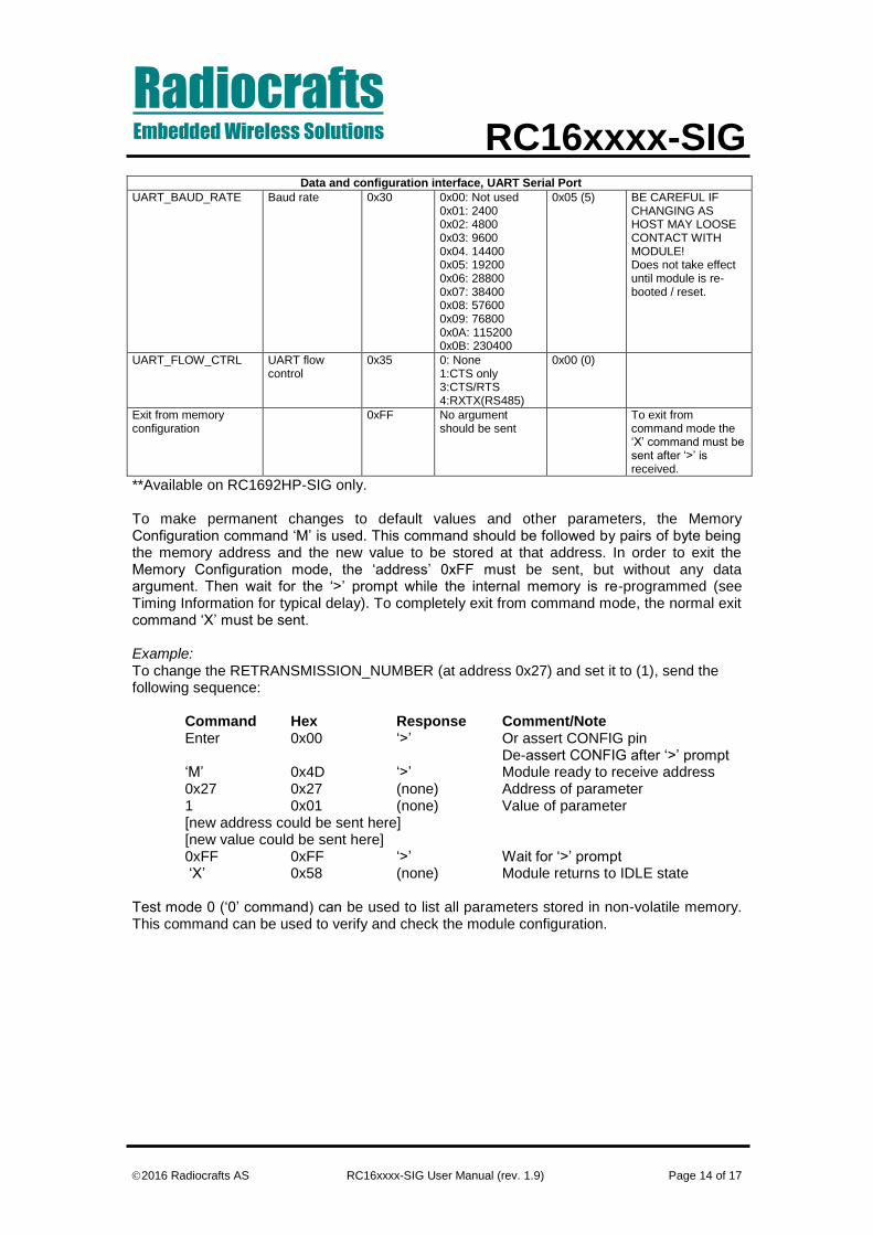
Data and configuration interface, UART Serial Port
UART_BAUD_RATE Baud rate 0x30 0x00: Not used 0x01: 2400 0x02: 4800 0x03: 9600 0x04. 14400 0x05: 19200 0x06: 28800 0x07: 38400 0x08: 57600 0x09: 76800 0x0A: 115200 0x0B: 230400
0x05 (5) BE CAREFUL IF CHANGING AS HOST MAY LOOSE CONTACT WITH MODULE! Does not take effect until module is re-booted / reset.
UART_FLOW_CTRL UART flow control
0x35 0: None 1:CTS only 3:CTS/RTS 4:RXTX(RS485)
0x00 (0)
Exit from memory configuration
0xFF No argument should be sent
To exit from command mode the ‘X’ command must be sent after ‘>’ is received.
**Available on RC1692HP-SIG only. To make permanent changes to default values and other parameters, the Memory Configuration command ‘M’ is used. This command should be followed by pairs of byte being the memory address and the new value to be stored at that address. In order to exit the Memory Configuration mode, the ‘address’ 0xFF must be sent, but without any data argument. Then wait for the ‘>’ prompt while the internal memory is re-programmed (see Timing Information for typical delay). To completely exit from command mode, the normal exit command ‘X’ must be sent. Example: To change the RETRANSMISSION_NUMBER (at address 0x27) and set it to (1), send the following sequence: Command Hex Response Comment/Note Enter 0x00 ‘>’ Or assert CONFIG pin
De-assert CONFIG after ‘>’ prompt ‘M’ 0x4D ‘>’ Module ready to receive address
0x27 0x27 (none) Address of parameter 1 0x01 (none) Value of parameter [new address could be sent here] [new value could be sent here] 0xFF 0xFF ‘>’ Wait for ‘>’ prompt ‘X’ 0x58 (none) Module returns to IDLE state
Test mode 0 (‘0’ command) can be used to list all parameters stored in non-volatile memory. This command can be used to verify and check the module configuration.

RadiocraftsEmbedded Wireless Solutions RC16xxxx-SIG
2016 Radiocrafts AS RC16xxxx-SIG User Manual (rev. 1.9) Page 15 of 17
Factory values of configuration memory RC1682-SIG
00 00 00 00 00 00 00 00
05 3C 00 00 00 00 00 00
7C 00 00 01 00 00 00 00
00 00 00 00 00 00 00 00
00 00 00 00 00 00 00 02
00 00 00 00 00 00 32 00
05 08 00 01 00 00 00 00
00 00 00 00 00 00 00 00
00 00 00 00 00 00 00 00
00 00 00 00 00 00 00 00
00 00 00 00 00 00 00 00
00 00 00 00 00 00 00 00
00 00 00 00 00 00 00 00
00 00 00 00 00 00 00 00
00 00 00 00 00 00 00 00
00 00 00 00 00 00 00 00
00 00 00 00 00 00 00 00
00 52 43 31 36 38 32 2D
53 49 47 2C 31 2E 30 30
2C 31 2E 30 36 20 20 20
00 00 00 00 00 00 00 00
00 FF FF FF FF FF FF FF
FF FF FF FF FF FF FF FF
FF FF FF FF FF FF FF FF
FF FF FF FF FF FF FF FF
FF FF FF FF FF FF FF FF
FF FF FF FF FF FF FF FF
FF FF FF FF FF FF FF FF
FF FF FF FF FF FF FF FF
FF FF FF FF FF FF FF FF
FF FF FF FF FF FF FF FF
FF FF FF FF FF FF FF FF
FF
RC1692HP-SIG
01 05 00 00 00 00 00 00
05 3C 00 00 00 00 00 00
7C 00 00 01 00 00 00 00
00 00 00 00 00 00 00 00
00 00 00 00 00 00 00 02
00 00 00 00 00 00 32 00
05 08 00 01 00 00 00 00
00 00 00 00 00 00 00 00
00 00 00 00 00 00 00 00
00 00 00 00 00 00 00 00
00 00 00 00 00 00 00 00
00 00 00 00 00 00 00 00
00 00 00 00 00 00 00 00
00 00 00 00 00 00 00 00
00 00 00 00 00 00 00 00
00 00 00 00 00 00 00 00
00 00 00 00 00 00 00 00
00 52 43 31 36 38 32 2D
53 49 47 2C 31 2E 30 30
2C 31 2E 30 36 20 20 20
00 00 00 00 00 00 00 00
00 FF FF FF FF FF FF FF
FF FF FF FF FF FF FF FF
FF FF FF FF FF FF FF FF
FF FF FF FF FF FF FF FF
FF FF FF FF FF FF FF FF
FF FF FF FF FF FF FF FF
FF FF FF FF FF FF FF FF
FF FF FF FF FF FF FF FF
FF FF FF FF FF FF FF FF
FF FF FF FF FF FF FF FF
FF FF FF FF FF FF FF FF
FF
Each value is represented as hex number.
RadiocraftsEmbedded Wireless Solutions RC16xxxx-SIG
2016 Radiocrafts AS RC16xxxx-SIG User Manual (rev. 1.9) Page 16 of 17
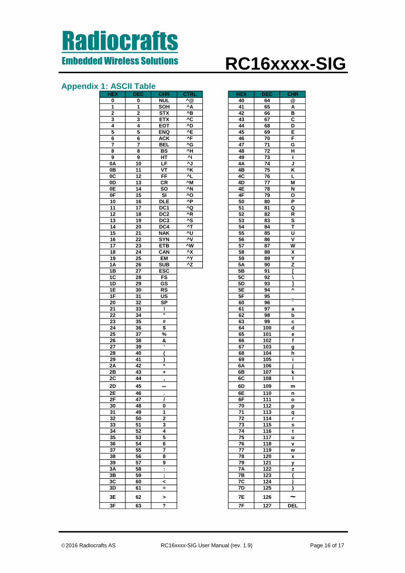
Appendix 1: ASCII Table HEX DEC CHR CTRL HEX DEC CHR
0 0 NUL ^@ 40 64 @
1 1 SOH ^A 41 65 A
2 2 STX ^B 42 66 B
3 3 ETX ^C 43 67 C
4 4 EOT ^D 44 68 D
5 5 ENQ ^E 45 69 E
6 6 ACK ^F 46 70 F
7 7 BEL ^G 47 71 G
8 8 BS ^H 48 72 H
9 9 HT ^I 49 73 I
0A 10 LF ^J 4A 74 J
0B 11 VT ^K 4B 75 K
0C 12 FF ^L 4C 76 L
0D 13 CR ^M 4D 77 M
0E 14 SO ^N 4E 78 N
0F 15 SI ^O 4F 79 O
10 16 DLE ^P 50 80 P
11 17 DC1 ^Q 51 81 Q
12 18 DC2 ^R 52 82 R
13 19 DC3 ^S 53 83 S
14 20 DC4 ^T 54 84 T
15 21 NAK ^U 55 85 U
16 22 SYN ^V 56 86 V
17 23 ETB ^W 57 87 W
18 24 CAN ^X 58 88 X
19 25 EM ^Y 59 89 Y
1A 26 SUB ^Z 5A 90 Z
1B 27 ESC 5B 91 [
1C 28 FS 5C 92 \
1D 29 GS 5D 93 ]
1E 30 RS 5E 94 ^
1F 31 US 5F 95 _
20 32 SP 60 96 `
21 33 ! 61 97 a
22 34 " 62 98 b
23 35 # 63 99 c
24 36 $ 64 100 d
25 37 % 65 101 e
26 38 & 66 102 f
27 39 ' 67 103 g
28 40 ( 68 104 h
29 41 ) 69 105 i
2A 42 * 6A 106 j
2B 43 + 6B 107 k
2C 44 , 6C 108 l
2D 45 6D 109 m
2E 46 . 6E 110 n
2F 47 / 6F 111 o
30 48 0 70 112 p
31 49 1 71 113 q
32 50 2 72 114 r
33 51 3 73 115 s
34 52 4 74 116 t
35 53 5 75 117 u
36 54 6 76 118 v
37 55 7 77 119 w
38 56 8 78 120 x
39 57 9 79 121 y
3A 58 : 7A 122 z
3B 59 ; 7B 123 {
3C 60 < 7C 124 |
3D 61 = 7D 125 }
3E 62 > 7E 126 ~3F 63 ? 7F 127 DEL
RadiocraftsEmbedded Wireless Solutions RC16xxxx-SIG
2016 Radiocrafts AS RC16xxxx-SIG User Manual (rev. 1.9) Page 17 of 17
Document Revision History Document Revision Changes
1.0 First release
1.1 Expanded information is available on periodic OOB frame transmission. Corrected formal errors. Added Length byte to RX.
1.2 Corrected range of OOB period to 15h.
1.3 – 1.5 Internal releases
1.6 Timing information added
1.7 Corrected texts.
1.8 Corrected text.
1.9 Renamed document to RC16xxxx-SIG and added details related to the RC1692HP-SIG variant.
Disclaimer
Radiocrafts AS believes the information contained herein is correct and accurate at the time of this printing. However, Radiocrafts AS reserves the right to make changes to this product without notice. Radiocrafts AS does not assume any responsibility for the use of the described product; neither does it convey any license under its patent rights, or the rights of others. The latest updates are available at the Radiocrafts website or by contacting Radiocrafts directly. As far as possible, major changes of product specifications and functionality, will be stated in product specific Errata Notes published at the Radiocrafts website. Customers are encouraged to check regularly for the most recent updates on products and support tools.
Trademarks
SIGFOX™ is a trademark of the SIGFOX company (France). RC16XXXX-SIG™ is a trademark of Radiocrafts AS. All other trademarks, registered trademarks and product names are the sole property of their respective owners.
Life Support Policy This Radiocrafts product is not designed for use in life support appliances, devices, or other systems where malfunction can reasonably be expected to result in significant personal injury to the user, or as a critical component in any life support device or system whose failure to perform can be reasonably expected to cause the failure of the life support device or system, or to affect its safety or effectiveness. Radiocrafts AS customers using or selling these products for use in such applications do so at their own risk and agree to fully indemnify Radiocrafts AS for any damages resulting from any improper use or sale.
© 2016, Radiocrafts AS. All rights reserved.
Contact Information Web site: www.radiocrafts.com Address: Radiocrafts AS Sandakerveien 64 NO-0484 OSLO NORWAY Tel: +47 40 00 51 95 Fax: +47 22 71 29 15 E-mails: [email protected]
Recommended