Research ArticleMultiscale Modeling of Elastic Properties of SustainableConcretes by Microstructural-Based Micromechanics
V. Zanjani Zadeh and C. P. Bobko
Department of Civil, Construction and Environmental Engineering, North Carolina State University,Campus Box 7908, Raleigh, NC 27695-7908, USA
Correspondence should be addressed to C. P. Bobko; chris [email protected]
Received 20 May 2014; Revised 29 September 2014; Accepted 30 September 2014; Published 2 November 2014
Academic Editor: Baozhong Sun
Copyright © 2014 V. Zanjani Zadeh and C. P. Bobko. This is an open access article distributed under the Creative CommonsAttribution License, which permits unrestricted use, distribution, and reproduction in any medium, provided the original work isproperly cited.
This paper addresses multiscale stiffness homogenization methodology to extract macroscale elastic mechanical properties offour types of sustainable concretes from their nanoscale mechanical properties. Nine different sustainable concrete mixtures werestudied. A model based on micromechanics was used to homogenize the elastic properties. The hardened cement pastes werehomogenized by three analytical methods based on Self-Consistent and Mori-Tanaka schemes. The proposed multiscale methodcombines advanced experimental and analytical methods in a systematic way so that the inputs are nanoscale phases propertiesextracted from statistical nanoindentation technique and mechanical properties of mixture ingredient. Predicted elastic propertieswere consistent with traditional experimental results. Linking homogenized mechanical properties of sustainable concrete tovolume proportions through an analytical approach provides a critical first step towards rational optimization of these materials.
1. Introduction
Concrete is a complex heterogeneous material whose me-chanical properties can vary substantially from point topoint. Predicting the mechanical behavior of such materialsalways has been a challenge confronting scientists. However,progress in both experimentation and continuum micro-mechanics has provided the required foundations for thedevelopment of multiscale models for complex heteroge-neous materials such as concrete. These upscaling schemeswork as ways to exchange information about mechanicalproperties between different scales of a model. Furthermore,performance-oriented optimization of the homogenizedproperties becomes possible by considering modificationsto the material chemistry, composition, processes, and theirrelated impacts on microstructure.
2. Background
2.1. Sustainable Concrete. Concrete containing fly ash andblast furnace slag, kenaf fiber reinforced concrete (KFRC),
and lightweight aggregate concrete (LWAC) can be catego-rized as sustainable concrete, by achieving concrete with highstrength while reducing cement consumption. Plant-basednatural fibers, such as kenaf bast fibers, can be used inconcrete to obtain a new lighter weight and yet tougherconcrete while maintaining desirable material propertieswill directly enhance the merits of precast concrete [1]. CO
2
sequestration is another positive impact of kenaf. One acreof kenaf captures as much CO
2as three acres of rain forest,
and much of the captured CO2can be permanently trapped
inside structures used in construction [2]. Additionally, thelighter weight and better performance will reduce the energyrequirements and greenhouse gas emissions associated withconcrete manufacturing and delivery.
Using fly ash (FA) and ground granular blast furnaceslag (GGBS) reduces greenhouse gas emissions, since unlikePortland cement their reaction with water does not produceCO2. In addition to reducing CO
2emissions, other potential
benefits of using FA and GGBS include their disposal costs,significant opportunity to reduce landfill volumes, manufac-turing energy savings, lower-cost concrete, and reduction ofwater needed to produce the concrete [3, 4].
Hindawi Publishing CorporationJournal of CompositesVolume 2014, Article ID 758626, 10 pageshttp://dx.doi.org/10.1155/2014/758626
2 Journal of Composites
Being much lighter than conventional aggregates, dueto cellular or highly porous microstructure, lightweightaggregate (LWA) contributes to improved sustainability ofconcrete by reducing transportation cost [5]. Also, LWAshavebetter fire resistance properties compared to conventionalaggregates [6]. Furthermore, LWAs often are made of wastematerials during a high temperature baking, which lessenthe need of using naturally occurring mineral aggregates,although tradeoffs in energy consumption during the man-ufacturing process must be weighed against the benefits.Besides direct contribution of LWA to sustainability, it mayhave a positive effect on mechanical properties of concrete.Theuse of internal curing generated by LWAcan substantiallymitigate self-desiccation and resulting autogenous deforma-tion and cracking thus reducing transport properties such asdiffusion and sorptivity [5]. This may increase the service lifeof concrete structures through more resistance against waterpermeability and freeze-thaw damage. Also, the enhancedhydration and increased compressive strengths providedby internal curing specifically in interfacial transition zone(ITZ), the volume surrounding aggregates, may allow forsmall but significant reductions in cement content in manyconcrete mixtures [7, 8]. All these benefits of LWA cancompensate the energy use during LWA production and cancontribute to significant improvements in sustainability.
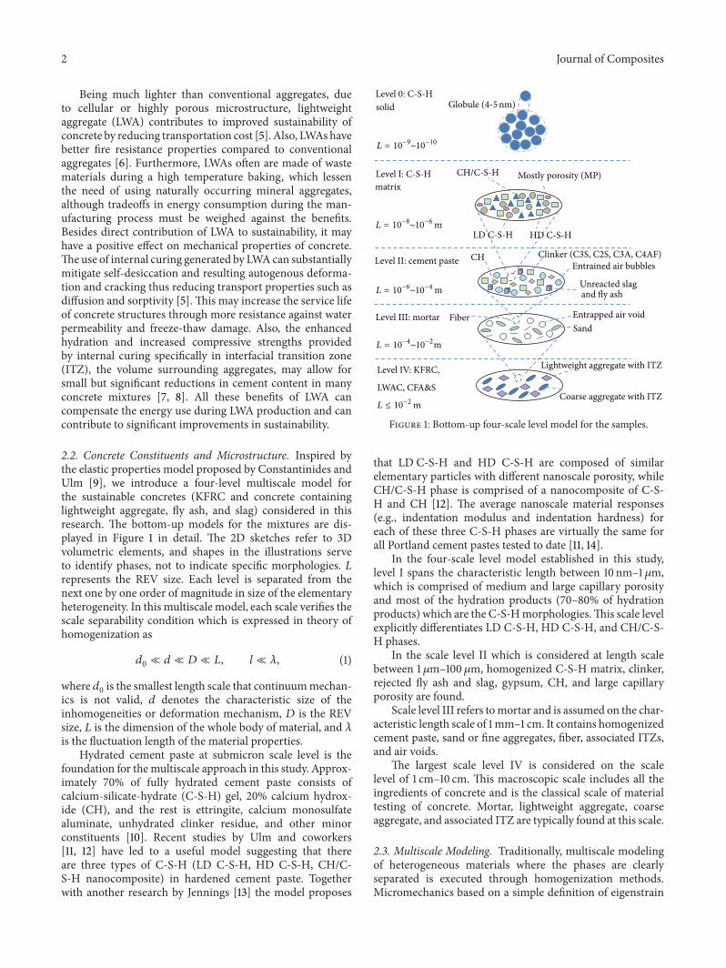
2.2. Concrete Constituents and Microstructure. Inspired bythe elastic properties model proposed by Constantinides andUlm [9], we introduce a four-level multiscale model forthe sustainable concretes (KFRC and concrete containinglightweight aggregate, fly ash, and slag) considered in thisresearch. The bottom-up models for the mixtures are dis-played in Figure 1 in detail. The 2D sketches refer to 3Dvolumetric elements, and shapes in the illustrations serveto identify phases, not to indicate specific morphologies. 𝐿represents the REV size. Each level is separated from thenext one by one order of magnitude in size of the elementaryheterogeneity. In this multiscale model, each scale verifies thescale separability condition which is expressed in theory ofhomogenization as
𝑑0≪ 𝑑 ≪ 𝐷 ≪ 𝐿, 𝑙 ≪ 𝜆, (1)
where 𝑑0is the smallest length scale that continuummechan-
ics is not valid, 𝑑 denotes the characteristic size of theinhomogeneities or deformation mechanism, 𝐷 is the REVsize, 𝐿 is the dimension of the whole body of material, and 𝜆
is the fluctuation length of the material properties.Hydrated cement paste at submicron scale level is the
foundation for themultiscale approach in this study. Approx-imately 70% of fully hydrated cement paste consists ofcalcium-silicate-hydrate (C-S-H) gel, 20% calcium hydrox-ide (CH), and the rest is ettringite, calcium monosulfatealuminate, unhydrated clinker residue, and other minorconstituents [10]. Recent studies by Ulm and coworkers[11, 12] have led to a useful model suggesting that thereare three types of C-S-H (LD C-S-H, HD C-S-H, CH/C-S-H nanocomposite) in hardened cement paste. Togetherwith another research by Jennings [13] the model proposes
matrix
Level II: cement paste
Level III: mortar Entrapped air voidFiberSand
Level IV: KFRC,
L ≤ 10−2 mCoarse aggregate with ITZ
Mostly porosity (MP)
Entrained air bubbles
Globule (4-5nm)solid
CH Clinker (C3S, C2S, C3A, C4AF)
Unreacted slagand fly ash
Lightweight aggregate with ITZ
Level I: C-S-H
Level 0: C-S-H
HD C-S-HLD C-S-H
CH/C-S-H
LWAC, CFA&S
L = 10−9∼10−10
L = 10−6∼10−4 m
L = 10−8∼10−6 m
L = 10−4∼10−2m
Figure 1: Bottom-up four-scale level model for the samples.
that LD C-S-H and HD C-S-H are composed of similarelementary particles with different nanoscale porosity, whileCH/C-S-H phase is comprised of a nanocomposite of C-S-H and CH [12]. The average nanoscale material responses(e.g., indentation modulus and indentation hardness) foreach of these three C-S-H phases are virtually the same forall Portland cement pastes tested to date [11, 14].
In the four-scale level model established in this study,level I spans the characteristic length between 10 nm–1 𝜇m,which is comprised of medium and large capillary porosityand most of the hydration products (70–80% of hydrationproducts) which are the C-S-Hmorphologies.This scale levelexplicitly differentiates LD C-S-H, HD C-S-H, and CH/C-S-H phases.
In the scale level II which is considered at length scalebetween 1 𝜇m–100𝜇m, homogenized C-S-H matrix, clinker,rejected fly ash and slag, gypsum, CH, and large capillaryporosity are found.
Scale level III refers tomortar and is assumed on the char-acteristic length scale of 1mm–1 cm. It contains homogenizedcement paste, sand or fine aggregates, fiber, associated ITZs,and air voids.
The largest scale level IV is considered on the scalelevel of 1 cm–10 cm. This macroscopic scale includes all theingredients of concrete and is the classical scale of materialtesting of concrete. Mortar, lightweight aggregate, coarseaggregate, and associated ITZ are typically found at this scale.
2.3. Multiscale Modeling. Traditionally, multiscale modelingof heterogeneous materials where the phases are clearlyseparated is executed through homogenization methods.Micromechanics based on a simple definition of eigenstrain
Journal of Composites 3
in an inclusion came with Eshelby’s equivalent homogeniza-tion theory [15–17] and Hashin’s variational principle [18, 19].In 1960s, the early Voigt [20], Reuss [21], and Taylor [22]estimates were reassessed as bounds which became the basisfor so-called continuummicromechanics [23]. Effective fieldtheories based on the Eshelby elasticity solutionwith differentassumptions were developed for inhomogeneities embeddedin infinitemedia [24–26].Newdevelopments have beenmadecontinuously, with special mention of refined boundariesassociated with an improved morphological description andby means of special cases of media with periodic microstruc-tures [27–29].
Concrete is a highly heterogeneous composite construc-tion material whose microstructure contains randomly dis-persed features. The heterogeneity of concrete exists in avariety of length scales from nano to macro. It is widely rec-ognized that many macroscopic phenomena of the concreteoriginate from the mechanics of the underlying nano- andmicroscale structure. All themechanical, physical, and chem-ical properties of the ingredients including stiffness, strength,size, shape, volume fraction, and spatial distribution can haveimpact on the macroscale properties. The homogenizationfocuses on multiscale analysis due to the fact that typicalmaterial phases may be found at separable length scales asshown in Figure 1. Several multiscale micromechanical mod-eling techniques have been suggested for obtaining macro-scopic properties (elasticity, strength, etc.) of concrete fromknowledge of its nanoscale constituent properties, includingboth numerical (e.g., [30]) and analytical [31–34] approaches.
In this paper, multiscale modeling of mechanical prop-erties of four types of sustainable concretes is presented.A multistep, multiscale analytical micromechanics model isdefined based on morphology and length scale of the struc-tural elements in eachmaterial. Unlike the previous analyticalmodels that were proposed and used only in theoreticalproblems or for samples that were built in the laboratory,in this paper the multiscale model was used for sustainableconcretes including fly ash and blast furnace slag that werepoured and built in real condition. This is a leap forward inapplying multiscale modeling techniques to the sustainableconcrete industry instead of being used only in laboratory.The upscaled outcome of the modeling is compared withtraditional macroscopic results and they are found to beconsistent. Comparing the model prediction results withmacroscopic experimental data permits the validation of theapplied homogenization models. The validation itself can beemployed to validate the measured mechanical propertiesand morphology of the building blocks at the smallest lengthscales. Results from this research may help development ofguidelines that aim at optimizingmix designs of cementitiousmaterials with kenaf, LWA, and fly ash/slag for the desiredmechanical properties.
3. Effective Elastic Modulus ofHeterogeneous Materials
A three-step homogenization scheme is developed to bridgethe four length scale levels in order to obtain elasticity con-stants of the samples in macroscopic scale from knowledge
of the volume fractions. Continuummicromechanics offers aframework to address this challenge.
Continuum micromechanics relies on the concept of aconcentration tensor which is able to bridge the gap betweenlocal stress and strain fields (𝜎, 𝜀) from macroscopic ones (Σ,𝐸) as follows:
Σ = A : 𝜎, 𝐸 = B : 𝜀, (2)
in which A and B are fourth-order stain and stress localiza-tion (concentration) tensors.
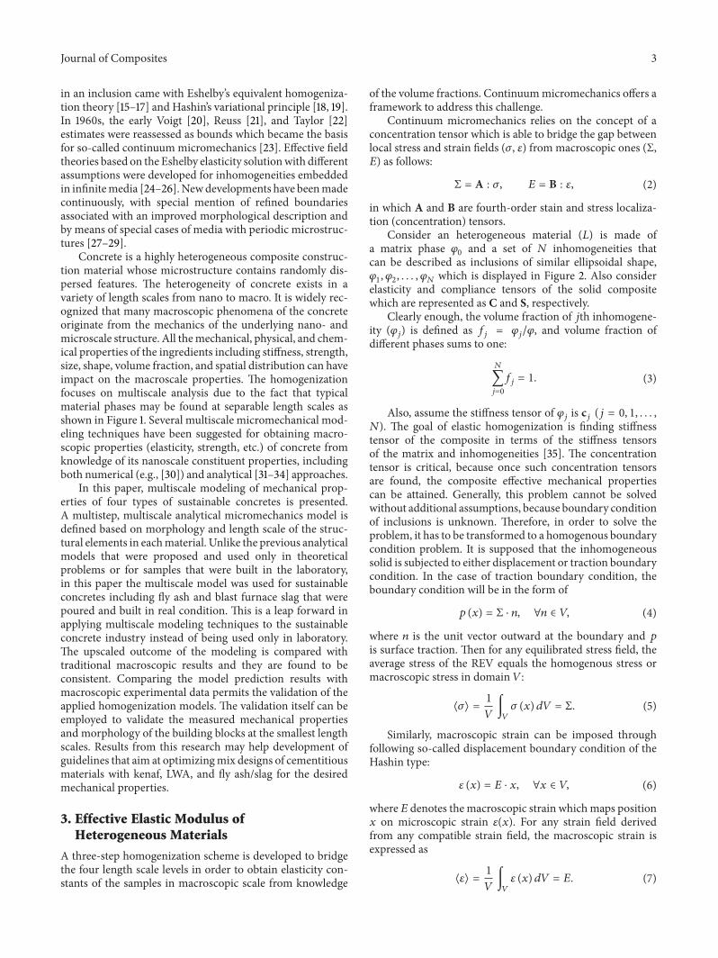
Consider an heterogeneous material (𝐿) is made ofa matrix phase 𝜑
0and a set of 𝑁 inhomogeneities that
can be described as inclusions of similar ellipsoidal shape,𝜑1, 𝜑2, . . . , 𝜑
𝑁which is displayed in Figure 2. Also consider
elasticity and compliance tensors of the solid compositewhich are represented as C and S, respectively.
Clearly enough, the volume fraction of 𝑗th inhomogene-ity (𝜑
𝑗) is defined as 𝑓
𝑗= 𝜑𝑗/𝜑, and volume fraction of
different phases sums to one:
𝑁
∑
𝑗=0
𝑓𝑗= 1. (3)
Also, assume the stiffness tensor of 𝜑𝑗is c𝑗(𝑗 = 0, 1, . . . ,
𝑁). The goal of elastic homogenization is finding stiffnesstensor of the composite in terms of the stiffness tensorsof the matrix and inhomogeneities [35]. The concentrationtensor is critical, because once such concentration tensorsare found, the composite effective mechanical propertiescan be attained. Generally, this problem cannot be solvedwithout additional assumptions, because boundary conditionof inclusions is unknown. Therefore, in order to solve theproblem, it has to be transformed to a homogenous boundarycondition problem. It is supposed that the inhomogeneoussolid is subjected to either displacement or traction boundarycondition. In the case of traction boundary condition, theboundary condition will be in the form of
𝑝 (𝑥) = Σ ⋅ 𝑛, ∀𝑛 ∈ 𝑉, (4)
where 𝑛 is the unit vector outward at the boundary and 𝑝
is surface traction. Then for any equilibrated stress field, theaverage stress of the REV equals the homogenous stress ormacroscopic stress in domain 𝑉:
⟨𝜎⟩ =1
𝑉∫𝑉
𝜎 (𝑥) 𝑑𝑉 = Σ. (5)
Similarly, macroscopic strain can be imposed throughfollowing so-called displacement boundary condition of theHashin type:
𝜀 (𝑥) = 𝐸 ⋅ 𝑥, ∀𝑥 ∈ 𝑉, (6)
where 𝐸 denotes themacroscopic strain whichmaps position𝑥 on microscopic strain 𝜀(𝑥). For any strain field derivedfrom any compatible strain field, the macroscopic strain isexpressed as
⟨𝜀⟩ =1
𝑉∫𝑉
𝜀 (𝑥) 𝑑𝑉 = 𝐸. (7)
4 Journal of Composites
L
𝜑0
𝜑3𝜑1
𝜑2
𝜑4
𝜑5 𝜑6
𝜑N
Figure 2: Composite material with 𝑁 inhomogeneities.
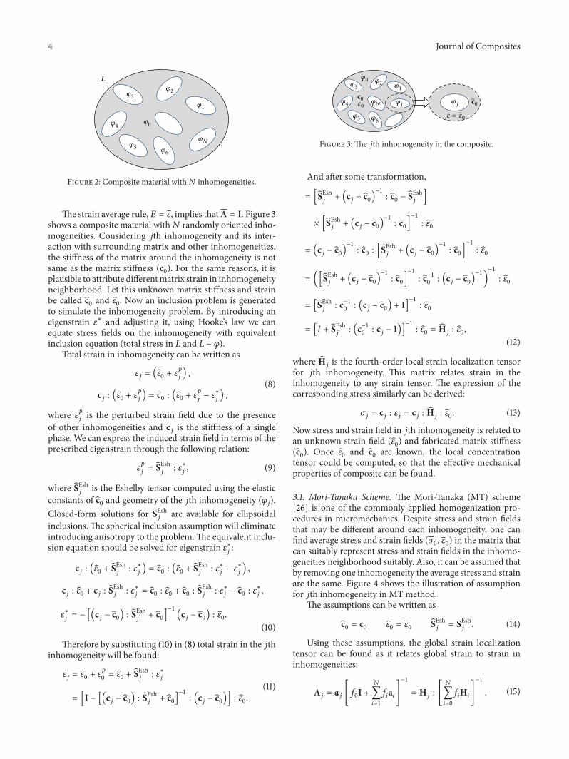
The strain average rule, 𝐸 = 𝜀, implies thatA = I. Figure 3shows a composite material with𝑁 randomly oriented inho-mogeneities. Considering 𝑗th inhomogeneity and its inter-action with surrounding matrix and other inhomogeneities,the stiffness of the matrix around the inhomogeneity is notsame as the matrix stiffness (c
0). For the same reasons, it is
plausible to attribute differentmatrix strain in inhomogeneityneighborhood. Let this unknown matrix stiffness and strainbe called c
0and 𝜀0. Now an inclusion problem is generated
to simulate the inhomogeneity problem. By introducing aneigenstrain 𝜀
∗ and adjusting it, using Hooke’s law we canequate stress fields on the inhomogeneity with equivalentinclusion equation (total stress in 𝐿 and 𝐿 − 𝜑).
Total strain in inhomogeneity can be written as
𝜀𝑗= (𝜀0+ 𝜀𝑝
𝑗) ,
c𝑗: (𝜀0+ 𝜀𝑝
𝑗) = c0: (𝜀0+ 𝜀𝑝
𝑗− 𝜀∗
𝑗) ,
(8)
where 𝜀𝑝
𝑗is the perturbed strain field due to the presence
of other inhomogeneities and c𝑗is the stiffness of a single
phase. We can express the induced strain field in terms of theprescribed eigenstrain through the following relation:
𝜀𝑝
𝑗= SEsh𝑗
: 𝜀∗
𝑗, (9)
where SEsh𝑗
is the Eshelby tensor computed using the elasticconstants of c
0and geometry of the 𝑗th inhomogeneity (𝜑
𝑗).
Closed-form solutions for SEsh𝑗
are available for ellipsoidalinclusions.The spherical inclusion assumption will eliminateintroducing anisotropy to the problem.The equivalent inclu-sion equation should be solved for eigenstrain 𝜀
∗
𝑗:
c𝑗: (𝜀0+ SEsh𝑗
: 𝜀∗
𝑗) = c0: (𝜀0+ SEsh𝑗
: 𝜀∗
𝑗− 𝜀∗
𝑗) ,
c𝑗: 𝜀0+ c𝑗: SEsh𝑗
: 𝜀∗
𝑗= c0: 𝜀0+ c0: SEsh𝑗
: 𝜀∗
𝑗− c0: 𝜀∗
𝑗,
𝜀∗
𝑗= − [(c
𝑗− c0) : SEsh𝑗
+ c0]−1
(c𝑗− c0) : 𝜀0.
(10)
Therefore by substituting (10) in (8) total strain in the 𝑗thinhomogeneity will be found:
𝜀𝑗= 𝜀0+ 𝜀𝑝
0= 𝜀0+ SEsh𝑗
: 𝜀∗
𝑗
= [I − [(c𝑗− c0) : SEsh𝑗
+ c0]−1
: (c𝑗− c0)] : 𝜀0.
(11)
𝜑0𝜑1
𝜑2𝜑3
𝜑4
𝜑5 𝜑6
𝜑N 𝜑j𝜑j𝜀0
𝜀 = ��0
00 cc
Figure 3: The 𝑗th inhomogeneity in the composite.
And after some transformation,
= [SEsh𝑗
+ (c𝑗− c0)−1
: c0− SEsh𝑗
]
× [SEsh𝑗
+ (c𝑗− c0)−1
: c0]
−1
: 𝜀0
= (c𝑗− c0)−1
: c0: [SEsh𝑗
+ (c𝑗− c0)−1
: c0]
−1
: 𝜀0
= ([SEsh𝑗
+ (c𝑗− c0)−1
: c0]
−1
: c−10
: (c𝑗− c0)−1
)
−1
: 𝜀0
= [SEsh𝑗
: c−10
: (c𝑗− c0) + I]
−1
: 𝜀0
= [𝐼 + SEsh𝑗
: (c−10
: c𝑗− I)]−1
: 𝜀0= H𝑗: 𝜀0,
(12)
where H𝑗is the fourth-order local strain localization tensor
for 𝑗th inhomogeneity. This matrix relates strain in theinhomogeneity to any strain tensor. The expression of thecorresponding stress similarly can be derived:
𝜎𝑗= c𝑗: 𝜀𝑗= c𝑗: H𝑗: 𝜀0. (13)
Now stress and strain field in 𝑗th inhomogeneity is related toan unknown strain field (𝜀
0) and fabricated matrix stiffness
(c0). Once 𝜀
0and c
0are known, the local concentration
tensor could be computed, so that the effective mechanicalproperties of composite can be found.
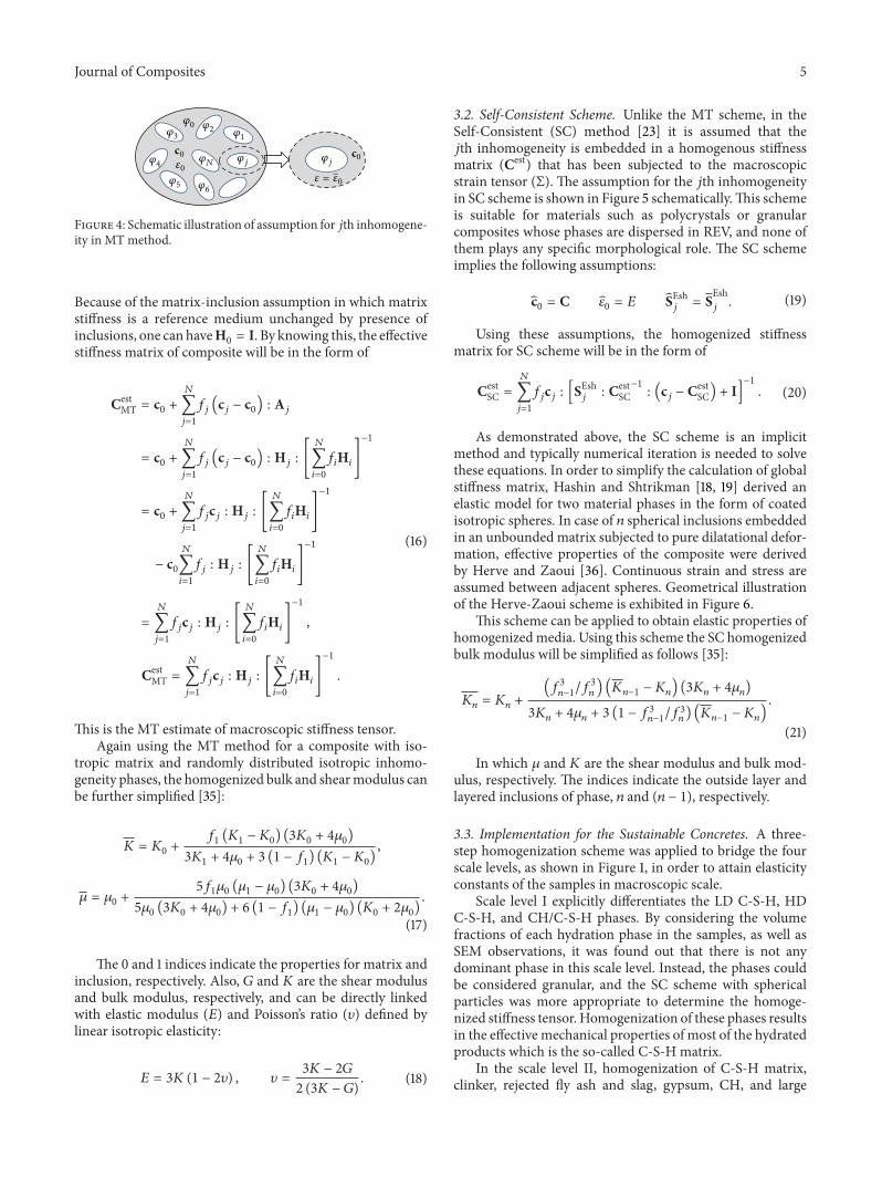
3.1. Mori-Tanaka Scheme. The Mori-Tanaka (MT) scheme[26] is one of the commonly applied homogenization pro-cedures in micromechanics. Despite stress and strain fieldsthat may be different around each inhomogeneity, one canfind average stress and strain fields (𝜎
0, 𝜀0) in the matrix that
can suitably represent stress and strain fields in the inhomo-geneities neighborhood suitably. Also, it can be assumed thatby removing one inhomogeneity the average stress and strainare the same. Figure 4 shows the illustration of assumptionfor 𝑗th inhomogeneity in MT method.
The assumptions can be written as
c0= c0
𝜀0= 𝜀0
SEsh𝑗
= SEsh𝑗
. (14)
Using these assumptions, the global strain localizationtensor can be found as it relates global strain to strain ininhomogeneities:
A𝑗= a𝑗[𝑓0I +𝑁
∑
𝑖=1
𝑓𝑖a𝑖]
−1
= H𝑗: [
𝑁
∑
𝑖=0
𝑓𝑖H𝑖]
−1
. (15)
Journal of Composites 5
𝜑0𝜑1
𝜑2𝜑3
𝜑4
𝜑5 𝜑6
𝜑N 𝜑j𝜑j𝜀0𝜀 = 𝜀0
0 0cc
Figure 4: Schematic illustration of assumption for 𝑗th inhomogene-ity in MT method.
Because of the matrix-inclusion assumption in which matrixstiffness is a reference medium unchanged by presence ofinclusions, one can haveH
0= I. By knowing this, the effective
stiffness matrix of composite will be in the form of
CestMT = c
0+
𝑁
∑
𝑗=1
𝑓𝑗(c𝑗− c0) : A𝑗
= c0+
𝑁
∑
𝑗=1
𝑓𝑗(c𝑗− c0) : H𝑗: [
𝑁
∑
𝑖=0
𝑓𝑖H𝑖]
−1
= c0+
𝑁
∑
𝑗=1
𝑓𝑗c𝑗: H𝑗: [
𝑁
∑
𝑖=0
𝑓𝑖H𝑖]
−1
− c0
𝑁
∑
𝑖=1
𝑓𝑗: H𝑗: [
𝑁
∑
𝑖=0
𝑓𝑖H𝑖]
−1
=
𝑁
∑
𝑗=1
𝑓𝑗c𝑗: H𝑗: [
𝑁
∑
𝑖=0
𝑓𝑖H𝑖]
−1
,
CestMT =
𝑁
∑
𝑗=1
𝑓𝑗c𝑗: H𝑗: [
𝑁
∑
𝑖=0
𝑓𝑖H𝑖]
−1
.
(16)
This is the MT estimate of macroscopic stiffness tensor.Again using the MT method for a composite with iso-
tropic matrix and randomly distributed isotropic inhomo-geneity phases, the homogenized bulk and shearmodulus canbe further simplified [35]:
𝐾 = 𝐾0+
𝑓1(𝐾1− 𝐾0) (3𝐾0+ 4𝜇0)
3𝐾1+ 4𝜇0+ 3 (1 − 𝑓
1) (𝐾1− 𝐾0),
𝜇 = 𝜇0+
5𝑓1𝜇0(𝜇1− 𝜇0) (3𝐾0+ 4𝜇0)
5𝜇0(3𝐾0+ 4𝜇0) + 6 (1 − 𝑓
1) (𝜇1− 𝜇0) (𝐾0+ 2𝜇0).
(17)
The 0 and 1 indices indicate the properties for matrix andinclusion, respectively. Also, 𝐺 and 𝐾 are the shear modulusand bulk modulus, respectively, and can be directly linkedwith elastic modulus (𝐸) and Poisson’s ratio (𝜐) defined bylinear isotropic elasticity:
𝐸 = 3𝐾 (1 − 2𝜐) , 𝜐 =3𝐾 − 2𝐺
2 (3𝐾 − 𝐺). (18)
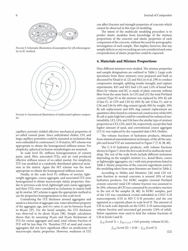
3.2. Self-Consistent Scheme. Unlike the MT scheme, in theSelf-Consistent (SC) method [23] it is assumed that the𝑗th inhomogeneity is embedded in a homogenous stiffnessmatrix (Cest) that has been subjected to the macroscopicstrain tensor (Σ). The assumption for the 𝑗th inhomogeneityin SC scheme is shown in Figure 5 schematically.This schemeis suitable for materials such as polycrystals or granularcomposites whose phases are dispersed in REV, and none ofthem plays any specific morphological role. The SC schemeimplies the following assumptions:
c0= C 𝜀
0= 𝐸 SEsh
𝑗= SEsh𝑗
. (19)
Using these assumptions, the homogenized stiffnessmatrix for SC scheme will be in the form of
CestSC =
𝑁
∑
𝑗=1
𝑓𝑗c𝑗: [SEsh𝑗
: CestSC−1
: (c𝑗− Cest
SC) + I]−1
. (20)
As demonstrated above, the SC scheme is an implicitmethod and typically numerical iteration is needed to solvethese equations. In order to simplify the calculation of globalstiffness matrix, Hashin and Shtrikman [18, 19] derived anelastic model for two material phases in the form of coatedisotropic spheres. In case of 𝑛 spherical inclusions embeddedin an unbounded matrix subjected to pure dilatational defor-mation, effective properties of the composite were derivedby Herve and Zaoui [36]. Continuous strain and stress areassumed between adjacent spheres. Geometrical illustrationof the Herve-Zaoui scheme is exhibited in Figure 6.
This scheme can be applied to obtain elastic properties ofhomogenizedmedia. Using this scheme the SC homogenizedbulk modulus will be simplified as follows [35]:
𝐾𝑛= 𝐾𝑛+
(𝑓3
𝑛−1/𝑓3
𝑛) (𝐾𝑛−1
− 𝐾𝑛) (3𝐾𝑛+ 4𝜇𝑛)
3𝐾𝑛+ 4𝜇𝑛+ 3 (1 − 𝑓
3
𝑛−1/𝑓3𝑛) (𝐾𝑛−1
− 𝐾𝑛)
.
(21)
In which 𝜇 and 𝐾 are the shear modulus and bulk mod-ulus, respectively. The indices indicate the outside layer andlayered inclusions of phase, 𝑛 and (𝑛 − 1), respectively.
3.3. Implementation for the Sustainable Concretes. A three-step homogenization scheme was applied to bridge the fourscale levels, as shown in Figure 1, in order to attain elasticityconstants of the samples in macroscopic scale.
Scale level I explicitly differentiates the LD C-S-H, HDC-S-H, and CH/C-S-H phases. By considering the volumefractions of each hydration phase in the samples, as well asSEM observations, it was found out that there is not anydominant phase in this scale level. Instead, the phases couldbe considered granular, and the SC scheme with sphericalparticles was more appropriate to determine the homoge-nized stiffness tensor. Homogenization of these phases resultsin the effective mechanical properties of most of the hydratedproducts which is the so-called C-S-H matrix.
In the scale level II, homogenization of C-S-H matrix,clinker, rejected fly ash and slag, gypsum, CH, and large
6 Journal of Composites
𝜑0𝜑1
𝜑2𝜑3
𝜑4
𝜑5 𝜑6
𝜑N 𝜑j𝜑j𝜀0
0
𝜀 = E
Cc
Figure 5: Schematic illustration of assumption for 𝑗th inhomogene-ity in SC method.
Kn
K2
K1
r1
rn
r2
Figure 6: Geometrical illustration of multicoated spheres compos-ite.
capillary porosity yielded effective mechanical properties ofso-called cement paste. Since unhydrated clinker, CH, andlarge capillary porosities could be assumed as inclusions thatwere embedded in continuousC-S-Hmatrix,MT schemewasappropriate to obtain the homogenized stiffness tensor. Forsimplicity, spherical inclusion morphologies are assumed.
In scale level III, stiffness homogenization of cementpaste, sand, fiber, associated ITZs, and air void producedeffective stiffness tensor of so-called mortar. For simplicity,ITZ was modeled as a randomly distributed spherical inclu-sion in the matrix. Again the MT scheme was the mostappropriate to obtain the homogenized stiffness tensor.
Finally, in the scale level IV, stiffness of mortar, light-weight aggregate, coarse aggregate, and associated ITZ werehomogenized to obtain macroscopic elastic properties. Sim-ilar to previous scale level, lightweight and coarse aggregatesand their ITZs were considered as inclusions in matrix builtup by mortar. MT scheme is again the appropriate method touse for properties homogenization in this scale level.
Considering the ITZ thickness around aggregates andsands is a function of aggregate size, water absorbent propertyof the aggregate, age, and w/c ratio; it can be between 10 𝜇mto 80 𝜇m [37]. For the kenaf samples, the ITZ thicknesswas observed to be about 30 𝜇m [38]. Simple calculationshows that, by assuming 30 𝜇m and 10 𝜇m thicknesses ofITZ for coarse aggregate and sand, total volume fraction ofITZ will be less than 1%. Therefore ITZ of sand and coarseaggregates did not have significant effect on predictions ofmacroscopic elastic properties. However, weakness of ITZ
can affect fracture and strength properties of concrete whichcannot be observed in this type of modeling.
The intent of the multiscale modeling procedure is topredict elastic modulus from knowledge of the mixtureproportions of the concrete and elastic properties of eachcomponent of the concrete, without the need for petrographicinvestigation of each sample. This implies, however, that anysample defects ormicrocracking are not considered and someoverprediction of elastic properties could be expected.
4. Materials and Mixture Proportions
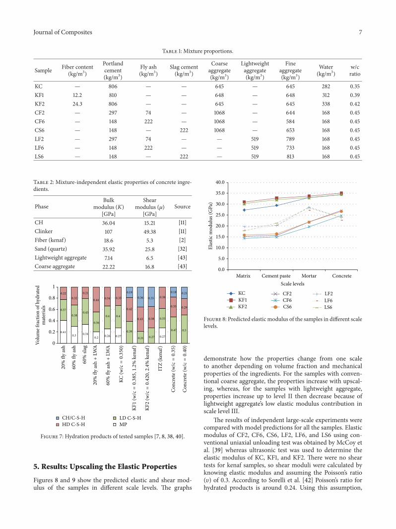
Nine different mixtures were studied.Themixture propertiesand sample designations are outlined in Table 1. Large scalespecimens from these mixtures were prepared and built asdiscussed by Elsaid et al. [2] andMcCoy et al. [39] to conductcompressive strength, splitting tensile strength, and ruptureexperiments. KF1 and KF2 had 1.2% and 2.4% of kenaf bastfibers by volume and KC is made of plain concrete withoutfiber from the same batch. In CF2 and LF2 the total Portlandcement (Type II) in the mixture was replaced by 20% fly ash(Class F), in CF6 and LF6 by 60% fly ash (Class F), and inCS6 and LS6 by 60% slag cement (grade 100) by weight. 20%fly ash replacement and 60% slag cement replacement arequantities often found in commercial constructionwhile 60%fly ash is quite high but could be considered for enhanced sus-tainability. LF2, LF6, and LS6 have the similar type ofmixtureproperties as CF2, CF6, andCS6, respectively, except they hadhigher amount of sand, and conventional course aggregate(CCA) was replaced by dry expanded slate LWA (Stalite).
The volume fractions of hydration products, obtainedfrom statistical nanoindentation technique, of the all the sam-ples and kenaf ITZ are summarized in Figure 7 [7, 8, 38, 40].
The C-S-H hydration products, with volume fractionsshown in Figure 7, form the first scale level inmultiscalemod-eling. The rest of the scale levels include different inclusionsdepending on the sample’s mixture (i.e., kenaf fibers, coarseor lightweight aggregates, etc.) with mix proportions listed inTable 1. Elastic properties of the concrete ingredients used inthe modeling taken from open literature are listed in Table 2.
According to Mehta and Monteiro [41] total CH vol-ume fraction in normal concretes is around 20% of totalhydration products. For KFRC samples (normal Portlandcement concrete) total CH volume fraction was assumed tobe 20%, whereas all CHwas consumed by secondary reactionin the rest of the samples [8, 40]. In KFRC samples, partof the CH was considered crystal embedded in CH/C-S-Hnanocomposite (CH in HD C-S-H porosity) and the restappeared as a separate phase in scale level II. The amount ofCH in each scale depends on the CH/C-S-H nanocompositevolume fraction and associated gel porosity (24% of solid).Below equations were used to find the volume fractions ofCH in levels I and II:
𝑓CH (Level I) = 𝑓HD C-S-H × Gel porosity volume (0.24) ,
𝑓CH (Level II) = 0.20 − 𝑓CH (Level I) .(22)
Journal of Composites 7
Table 1: Mixture proportions.
Sample Fiber content(kg/m3)
Portlandcement(kg/m3)
Fly ash(kg/m3)
Slag cement(kg/m3)
Coarseaggregate(kg/m3)
Lightweightaggregate(kg/m3)
Fineaggregate(kg/m3)
Water(kg/m3)
w/cratio
KC — 806 — — 645 — 645 282 0.35KF1 12.2 810 — — 648 — 648 312 0.39KF2 24.3 806 — — 645 — 645 338 0.42CF2 — 297 74 — 1068 — 644 168 0.45CF6 — 148 222 — 1068 — 584 168 0.45CS6 — 148 — 222 1068 — 653 168 0.45LF2 — 297 74 — — 519 789 168 0.45LF6 — 148 222 — — 519 733 168 0.45LS6 — 148 — 222 — 519 813 168 0.45
Table 2: Mixture-independent elastic properties of concrete ingre-dients.
PhaseBulk
modulus (𝐾)[GPa]
Shearmodulus (𝜇)
[GPa]Source
CH 36.04 15.21 [11]Clinker 107 49.38 [11]Fiber (kenaf) 18.6 5.3 [2]Sand (quartz) 35.92 25.8 [32]Lightweight aggregate 7.14 6.5 [43]Coarse aggregate 22.22 16.8 [43]
20
% fl
y as
h
60
% fl
y as
h
60
% sl
ag
KC (w
/c=0.350
)
KF1
(w/c=0.385
,1.2
% k
enaf
)
KF2
(w/c=0.420
,2.4
% k
enaf
)
ITZ
(ken
af)
Con
cret
e (w
/c=
0.35
)
Con
cret
e (w
/c=
0.40
)
ash+
LWA
20
% fl
y ash+
LWA
60
% fl
y
0.410.3 0.34
0.2 0.26 0.27 0.27
0.370.38
0.45
0.36
0.4 0.4
0.39
0.21 0.27
0.35
0.47 0.5
0.220.32
0.21
0.44 0.34 0.33
0.42
0.43 0.38
0.38
0.35 0.29
0.190.36 0.35
0.18 0.21
MPCH/C-S-HHD C-S-H
LD C-S-H
0
0.2
0.4
0.6
0.8
1
Volu
me f
ract
ion
of h
ydra
ted
mat
eria
ls
Figure 7: Hydration products of tested samples [7, 8, 38, 40].
5. Results: Upscaling the Elastic Properties
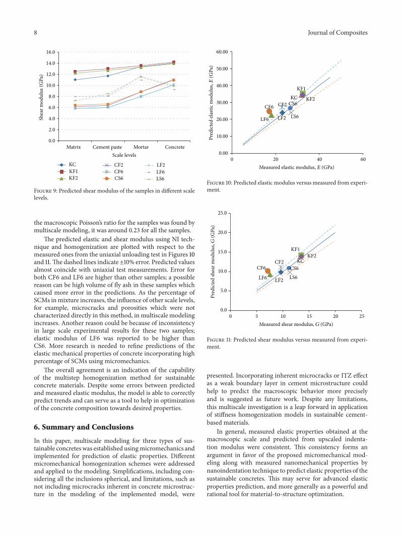
Figures 8 and 9 show the predicted elastic and shear mod-ulus of the samples in different scale levels. The graphs
0.0
5.0
10.0
15.0
20.0
25.0
30.0
35.0
40.0
Matrix Cement paste Mortar ConcreteScale levels
KCKF1KF2
CF2CF6CS6
LF2LF6LS6
Elas
tic m
odul
us (G
Pa)
Figure 8: Predicted elastic modulus of the samples in different scalelevels.
demonstrate how the properties change from one scaleto another depending on volume fraction and mechanicalproperties of the ingredients. For the samples with conven-tional coarse aggregate, the properties increase with upscal-ing, whereas, for the samples with lightweight aggregate,properties increase up to level II then decrease because oflightweight aggregate’s low elastic modulus contribution inscale level III.
The results of independent large-scale experiments werecompared with model predictions for all the samples. Elasticmodulus of CF2, CF6, CS6, LF2, LF6, and LS6 using con-ventional uniaxial unloading test was obtained by McCoy etal. [39] whereas ultrasonic test was used to determine theelastic modulus of KC, KF1, and KF2. There were no sheartests for kenaf samples, so shear moduli were calculated byknowing elastic modulus and assuming the Poisson’s ratio(𝜐) of 0.3. According to Sorelli et al. [42] Poisson’s ratio forhydrated products is around 0.24. Using this assumption,
8 Journal of Composites
0.0
2.0
4.0
6.0
8.0
10.0
12.0
14.0
16.0
Matrix Cement paste Mortar Concrete
Shea
r mod
ulus
(GPa
)
Scale levels
KCKF1KF2
CF2CF6CS6
LF2LF6LS6
Figure 9: Predicted shear modulus of the samples in different scalelevels.
the macroscopic Poisson’s ratio for the samples was found bymultiscale modeling, it was around 0.23 for all the samples.
The predicted elastic and shear modulus using NI tech-nique and homogenization are plotted with respect to themeasured ones from the uniaxial unloading test in Figures 10and 11.The dashed lines indicate ±10% error. Predicted valuesalmost coincide with uniaxial test measurements. Error forboth CF6 and LF6 are higher than other samples; a possiblereason can be high volume of fly ash in these samples whichcaused more error in the predictions. As the percentage ofSCMs inmixture increases, the influence of other scale levels,for example, microcracks and porosities which were notcharacterized directly in this method, in multiscale modelingincreases. Another reason could be because of inconsistencyin large scale experimental results for these two samples;elastic modulus of LF6 was reported to be higher thanCS6. More research is needed to refine predictions of theelastic mechanical properties of concrete incorporating highpercentage of SCMs using micromechanics.
The overall agreement is an indication of the capabilityof the multistep homogenization method for sustainableconcrete materials. Despite some errors between predictedand measured elastic modulus, the model is able to correctlypredict trends and can serve as a tool to help in optimizationof the concrete composition towards desired properties.
6. Summary and Conclusions
In this paper, multiscale modeling for three types of sus-tainable concretes was established usingmicromechanics andimplemented for prediction of elastic properties. Differentmicromechanical homogenization schemes were addressedand applied to the modeling. Simplifications, including con-sidering all the inclusions spherical, and limitations, such asnot including microcracks inherent in concrete microstruc-ture in the modeling of the implemented model, were
0.00
10.00
20.00
30.00
40.00
50.00
60.00
0 20 40 60
LF2
CF2KF2
KF1KC
CF6
LF6 LS6
CS6
Pred
icte
d el
astic
mod
ulus
,E(G
Pa)
Measured elastic modulus, E (GPa)
Figure 10: Predicted elastic modulus versus measured from experi-ment.
0.0
5.0
10.0
15.0
20.0
25.0
0 5 10 15 20 25
LF2
CF2KF2
KF1
KCCF6
LF6 LS6CS6
Pred
icte
d sh
ear m
odul
us,G
(GPa
)
Measured shear modulus, G (GPa)
Figure 11: Predicted shear modulus versus measured from experi-ment.
presented. Incorporating inherent microcracks or ITZ effectas a weak boundary layer in cement microstructure couldhelp to predict the macroscopic behavior more preciselyand is suggested as future work. Despite any limitations,this multiscale investigation is a leap forward in applicationof stiffness homogenization models in sustainable cement-based materials.
In general, measured elastic properties obtained at themacroscopic scale and predicted from upscaled indenta-tion modulus were consistent. This consistency forms anargument in favor of the proposed micromechanical mod-eling along with measured nanomechanical properties bynanoindentation technique to predict elastic properties of thesustainable concretes. This may serve for advanced elasticproperties prediction, and more generally as a powerful andrational tool for material-to-structure optimization.
Journal of Composites 9
Conflict of Interests
The authors declare that there is no conflict of interestsregarding the publication of this paper.
References
[1] T. R. Naik, “Sustainability of concrete construction,” ASCEPractice Periodical on Structural Design and Construction, vol.13, no. 2, pp. 98–103, 2008.
[2] A. Elsaid, M. Dawood, R. Seracino, and C. Bobko, “Mechanicalproperties of kenaf fiber reinforced concrete,” Construction andBuilding Materials, vol. 25, no. 4, pp. 1991–2001, 2010.
[3] American Concrete Institute, Use of Fly Ash in Concrete, ACI232.2R, American Concrete Institute, Farmington Hills, Mich,USA, 2003.
[4] “GroundGranulated Blast Furnace Slag as a Cementitious Con-stituent in Concrete,” ACI 233R, American Concrete Institute,Farmington Hills, Mich, USA, 2011.
[5] “ACI Manual, (308-213) R-13: Report on internally cured con-crete using prewetted absorptive lightweight aggregates,” 2013.
[6] S. Chandra and L. Berntsson, Lightweight Aggregate Concrete,Noyes, New York, NY, USA, 2002.
[7] V. Z. Zadeh and C. P. Bobko, “Nanomechanical investigation ofinternal curing effects on sustainable concretes with absorbentaggregates,” in Proceedings of the 5th Biot Conference on Porome-chanics (BIOT ’13), pp. 1625–1634, July 2013.
[8] V. Z. Zadeh and C. P. Bobko, “Nanomechanical characteristicsof lightweight aggregate concrete containing supplementarycementitious materials exposed to elevated temperature,” Con-struction and Building Materials, vol. 51, pp. 198–206, 2014.
[9] G. Constantinides and F. J. Ulm, “The effect of two types of C-S-H on the elasticity of cement-based materials: results fromnanoindentation and micromechanical modeling,” Cement andConcrete Research, vol. 34, no. 1, pp. 67–80, 2004.
[10] S. Diamond, “Cement paste microstructure—an overview atseveral levels,” in Hydraulic Cement Pastes: Their Structure andProperties, Proceedings of a Conference at Sheffield, pp. 2–31,University of Sheffield, Sheffield, UK, 1976.
[11] G. Constantinides and F.-J. Ulm, “The nanogranular nature ofC-S-H,” Journal of the Mechanics and Physics of Solids, vol. 55,no. 1, pp. 64–90, 2007.
[12] J. J. Chen, L. Sorelli, M. Vandamme, F.-J. Ulm, and G. Chanvil-lard, “A coupled nanoindentation/SEM-EDS study on lowwater/cement ratio portland cement paste: Evidence for C-S-H/Ca(OH)2 nanocomposites,” Journal of the American CeramicSociety, vol. 93, no. 5, pp. 1484–1493, 2010.
[13] H. M. Jennings, “A model for the microstructure of calciumsilicate hydrate in cement paste,”Cement and Concrete Research,vol. 30, no. 1, pp. 101–116, 2000.
[14] V. Zanjani Zadeh, Nanomechanics and multiscale modeling ofsustainable concretes [Ph.D. dissertation], North Carolina StateUniversity, 2013.
[15] J. D. Eshelby, “The determination of the elastic field of anellipsoidal inclusion, and related problems,” Proceedings of theRoyal Society. London. Series A. Mathematical, Physical andEngineering Sciences, vol. 241, pp. 376–396, 1957.
[16] J. D. Eshelby, “The elastic field outside an ellipsoidal inclusion,”Proceedings of the Royal Society A: Mathematical, Physical andEngineering Sciences, vol. 252, pp. 561–569, 1959.
[17] J. D. Eshelby, “Elastic inclusions and inhomogeneities,” inProgress in Solid Mechanics, N. I. Snedden and R. Hill, Eds., vol.2, pp. 89–104, North Holland, 1961.
[18] Z. Hashin and S. Shtrikman, “On some variational principlesin anisotropic and non-homogeneous elasticity,” Journal of theMechanics and Physics of Solids, vol. 10, pp. 335–342, 1962.
[19] Z. Hashin and S. Shtrikman, “A variational approach to thetheory of the elastic behaviour of polycrystals,” Journal of theMechanics and Physics of Solids, vol. 10, pp. 343–352, 1962.
[20] W. Voigt, “Theoretische studien uber die elastizitatsverha-itnisse der krystalle,”Abhandlungen der Koniglichen Gesellschaftder Wissenschaften zu Gottingen, Mathematisch-PhysikalischeKlasse, vol. 34, no. 1, 47 pages, 1887.
[21] A. Reuss, “Berchnung der Fliessgrenze von Mischkristallen aufgrund der plastizitatsbedingung fur einkristalle,” Zeitschrift furAngewandte Mathematik und Mechanik, vol. 9, no. 49, 1929.
[22] G. I. Taylor, “Plastic strain in metals,” Journal of the Institute ofMetals, vol. 62, pp. 307–324, 1938.
[23] R. Hill, “Elastic properties of reinforced solids,” Journal of theMechanics and Physics of Solids, vol. 11, no. 5, pp. 357–372, 1963.
[24] A. V. Hershey, “The elasticity of an isotropic aggregate ofanisotropic cubic crystals,” Journal of AppliedMechanics, vol. 21,pp. 236–240, 1954.
[25] E. Kroner, “Computation of the elastic constants of polycrystalsfrom constants of single crystals,” Zeitschriftfur Physik, vol. 151,pp. 504–518, 1958 (German).
[26] T. Mori and K. Tanaka, “Average stress in matrix and averageelastic energy of materials with misfitting inclusions,” ActaMetallurgica, vol. 21, no. 5, pp. 571–574, 1973.
[27] A. Bensoussan, J.-L. Lions, and G. Papanicolaou, AsymptoticAnalysis for Periodic Structures, North-Holland, 1978.
[28] E. Sanchez-Palencia, Non-Homogeneous Media and VibrationTheory, Springer, Berlin , Germany, 1980.
[29] P. Suquet, Elements of Homogenization for Inelastic SolidMechanics, Springer, 1987.
[30] E. J. Garboczi and D. P. Bentz, “Computer-based models ofthe microstructure and properties of cement-based materials,”in Proceedings of the 9th International Congress Chemistry ofCements, pp. 3–15, New Delhi, India, 1992.
[31] L. Dormieux, A. Molinari, and D. Kondo, “Micromechanicalapproach to the behavior of poroelasticmaterials,” Journal of theMechanics and Physics of Solids, vol. 50, no. 10, pp. 2203–2231,2002.
[32] F.-J. Ulm, G. Constantinides, and F. H. Heukamp, “Is concrete aporomechanicsmaterials?—amultiscale investigation of poroe-lastic properties,”Materials and Structures, vol. 37, no. 1, pp. 43–58, 2004.
[33] V. Smilauer and Z. Bittnar, “Microstructure-based microme-chanical prediction of elastic properties in hydrating cementpaste,” Cement and Concrete Research, vol. 36, no. 9, pp. 1708–1718, 2006.
[34] C. Pichler, R. Lackner, and H. A. Mang, “A multiscalemicromechanicsmodel for the autogenous-shrinkage deforma-tion of early-age cement-based materials,” Engineering FractureMechanics, vol. 74, no. 1-2, pp. 34–58, 2007.
[35] J. Qu and M. Cherkaoui, Fundamentals of Micromechanics ofSolids, John Wiley & Sons, Hoboken, NJ, USA, 2006.
[36] E. Herve and A. Zaoui, “n-Layered inclusion-based microme-chanical modelling,” International Journal of Engineering Sci-ence, vol. 31, no. 1, pp. 1–10, 1993.
10 Journal of Composites
[37] A. Elsharief, M. D. Cohen, and J. Olek, “Influence of aggregatesize, water cement ratio and age on the microstructure of theinterfacial transition zone,” Cement and Concrete Research, vol.33, no. 11, pp. 1837–1849, 2003.
[38] V. Z. Zadeh and C. P. Bobko, “Nano-mechanical properties ofinternally cured kenaf fiber reinforced concrete using nanoin-dentation,” Cement and Concrete Composites, vol. 52, pp. 9–17,2014.
[39] B. C. McCoy, M. L. Leming, and R. Seracino, “Crack densityand elastic properties of sustainable concretes,” ACI MaterialsJournal, vol. 111, no. 1, pp. 13–21, 2014.
[40] V. Zanjani Zadeh and C. P. Bobko, “Nanoscale mechanicalproperties of concrete containing blast furnace slag and flyash before and after thermal damage,” Cement and ConcreteComposites, vol. 37, no. 1, pp. 215–221, 2013.
[41] P. K. Mehta and P. J. M. Monteiro, Concrete: Microstructure,Properties, and Materials, Prentice-Hall, New York, NY, USA,3rd edition, 2006.
[42] L. Sorelli, G. Constantinides, F.-J. Ulm, and F. Toutlemonde,“The nano-mechanical signature of ultra high performanceconcrete by statistical nanoindentation techniques,”Cement andConcrete Research, vol. 38, no. 12, pp. 1447–1456, 2008.
[43] M. Alexander and S. Mindess, Aggregates in Concrete, Taylor &Francis, New York, NY, USA, 2005.

Submit your manuscripts athttp://www.hindawi.com
ScientificaHindawi Publishing Corporationhttp://www.hindawi.com Volume 2014
CorrosionInternational Journal of
Hindawi Publishing Corporationhttp://www.hindawi.com Volume 2014
Polymer ScienceInternational Journal of
Hindawi Publishing Corporationhttp://www.hindawi.com Volume 2014
Hindawi Publishing Corporationhttp://www.hindawi.com Volume 2014
CeramicsJournal of
Hindawi Publishing Corporationhttp://www.hindawi.com Volume 2014
CompositesJournal of
NanoparticlesJournal of
Hindawi Publishing Corporationhttp://www.hindawi.com Volume 2014
Hindawi Publishing Corporationhttp://www.hindawi.com Volume 2014
International Journal of
Biomaterials
Hindawi Publishing Corporationhttp://www.hindawi.com Volume 2014
NanoscienceJournal of
TextilesHindawi Publishing Corporation http://www.hindawi.com Volume 2014
Journal of
NanotechnologyHindawi Publishing Corporationhttp://www.hindawi.com Volume 2014
Journal of
CrystallographyJournal of
Hindawi Publishing Corporationhttp://www.hindawi.com Volume 2014
The Scientific World JournalHindawi Publishing Corporation http://www.hindawi.com Volume 2014
Hindawi Publishing Corporationhttp://www.hindawi.com Volume 2014
CoatingsJournal of
Advances in
Materials Science and EngineeringHindawi Publishing Corporationhttp://www.hindawi.com Volume 2014
Smart Materials Research
Hindawi Publishing Corporationhttp://www.hindawi.com Volume 2014
Hindawi Publishing Corporationhttp://www.hindawi.com Volume 2014
MetallurgyJournal of
Hindawi Publishing Corporationhttp://www.hindawi.com Volume 2014
BioMed Research International
MaterialsJournal of
Hindawi Publishing Corporationhttp://www.hindawi.com Volume 2014
Nano
materials
Hindawi Publishing Corporationhttp://www.hindawi.com Volume 2014
Journal ofNanomaterials
Recommended